

Page 1

SCC/SNC-C7478 Installation Guide
SCC/SNC-C7478
Installation Guide
36x PTZ Dome Camera
SAMSUNG | GVI Security, Inc
Phone: 972-245-7353 • Toll Free: 888-595-2288 • Fax: 972-245-7333
www.samsung-security.com
.
v.11.19.08
Page 2
SCC/SNC-C7478 Installation Guide
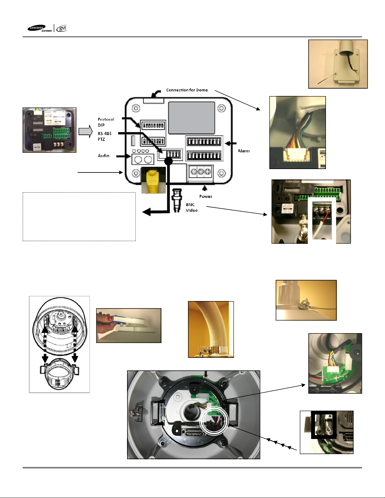
1. Remove junction box cover with supplied hex tool to view inner connection block.
Inner connection block exposes connections for power, video, alarm input/output as well
as dip switches for selecting camera ID, protocol, baud rate and termination.
(figure 1b)
manual for proper settings.
2. Attach wall mount to wall with supplied anchor bolts and make connections.
1b
Inner Box connections
RJ-45 Connection
*Note for RS-485 Connection:
GVI uses solid colored wire to represent positive (+) and striped wire for negative(-) polarity. Regardless of the wire color you choose
make sure polarity matches on both ends of
the connection
(figure 1a)
See
1a
2a
3. Remove camera mechanism from upper housing.
4. Use Teflon tape (included) to wrap around pipe fitting.
5. Attach safety cable to neck of mount.
(figure 5a)
6. Attach other end of safety cable to housing
(figure 6a)
(figure 3a)
(figure 4a)
and now screw in upper
housing to mount pole, bring in cable from pole mount and attach.
4a
Teflon tape for tight connection
3a
5a
Safety cable to mount
7. Pull retractable safety cable
from bottom of camera and
insert into hook, inside upper
housing.
SAMSUNG | GVI Security, Inc
Phone: 972-245-7353 • Toll Free: 888-595-2288 • Fax: 972-245-7333
www.samsung-security.com
(figure 7a)
Inside view of upper housing
.
(figure 6b)
Connection for power
6a
Safety cable to housing
6b
Cable connection for dome. Connect
cable from mount into upper housing
7a
Retractable safety cable
v.11.19.08
2b
Page 3

9. Attach fan and heater cables inside upper housing and attach dome cover safety
cable.
(figure 9a)
Fan/heater cable
10. Return PTZ camera mechanism into upper housing by pressing the
two black handles until camera mechanism snaps into
place.
(figure 10a)
11. Close the dome cover by matching the arrow markers. Be sure internal
cabling does not obstruct camera’s movement.
12. Orientation of housing my be adjusted by rotating the ring on which the
safety cable is attached.
12a
(figure 12a)
SCC/SNC-C7478 Installation Guide
Safety Cable
9a
10a
Completed mounted camera
Remove plastic covering carefully and power dome with 24 VAC 2.5 amps
SAMSUNG | GVI Security, Inc
Phone: 972-245-7353 • Toll Free: 888-595-2288 • Fax: 972-245-7333
www.samsung-security.com
.
v.11.19.08
Page 4

SNC-C7478 Setup Guide
IP Setup Guide
36x PTZ IP Dome Camera
SNC-C7478
1. Plug the included cross-over cable into the RJ-45 jack located inside the
inner connection block.
(figure 1a)
2. Plug the other end of the cross-over cable into the RJ-45 jack on back of
your computer.
(figure 2a)
3. From included CD, run the application titled IPInstaller. This will open a
window and scan your computer to locate the default IP address and subnet
mask assigned to the IP dome.
3a
(figure 3a)
1a
2a
4. Once camera has been identified within the window, you may view the default IP settings by first selecting
(clicking) the camera entry in the window, then choosing Manual Set in the lower right of the IPInstaller
window. Make note of the camera IP Address and the Subnet
Mask. You will refer to these in future steps.
(figure 4a)
After
4a
these values have been viewed and written down, you may cancel from the Manual Setting window and you may exit the
IPInstaller.
5. Next you will need to set your computer with a static IP address
as well as set your Subnet Mask to the same value as the IP PTZ
Dome Camera. (Subnet Mask value from previous step)
6. From your computer’s Control Panel go to Network and Internet Connections. Enter Network Connections
so that you are able to view all available Network Connections. Your screen should look similar to the
figure below.
SAMSUNG | GVI Security, Inc
Phone: 972-245-7353 • Toll Free: 888-595-2288 • Fax: 972-245-7333
www.samsung-security.com
(figure 6a)
6a
.
v.11.19.08
Page 5

7. Double click on Local Area Connection to bring up the Local Area Connection Status
box.
(figure 7a)
Click Properties in the lower left corner to display Local Area Connection
Properties.
8. From the Local Area Connection Properties window, double click
8a
Internet Protocol (TCP/IP) to display Internet Protocol (TCP/IP)
Properties.
(figure 8a)
9. Choose the option for Use the Following IP Address and type an
IP address that begins with 192.168.1. but use a number other
than the ending number assigned to the camera. (number must fall
between 1 and 255)
(figure 9a)
10. Type the subnet mask, this number must be the same as the
camera’s subnet mask, then choose OK at the bottom of the Internet Protocol (TCP/IP) Properties box.
11. You may now close out of the Network Connections window.
Accessing the Camera Menu from Internet Explorer
SNC-C7478 Setup Guide
7a
9a
12. After the above steps have been completed you may now use Microsoft’s Internet Explorer to enter the
camera’s setup menu.
13. Open an Internet Explorer window. In the address bar at the top of the window type HTTP:// followed by
the IP address assigned to your camera. (This value was obtained in step 4)
(figure 13a)
14. See users manual for full explanation of menus and
settings.
13a
15. Once you have finished with camera setup and have
exited from browser, be sure to go back into your
network settings and return all of your settings to
normal.
SAMSUNG | GVI Security, Inc
Phone: 972-245-7353 • Toll Free: 888-595-2288 • Fax: 972-245-7333
www.samsung-security.com
.
v.11.19.08
 Loading...