

Samsung SNC-B5399-N, SRN-873S User Manual

NETWORK VIDEO RECORDER
User Manual
SRN-473S/873S/1673S

Network Video Recorder
User Manual
Copyright
©2015 Samsung Techwin Co., Ltd. All rights reserved.
Trademark
The name of this product is the registered trademark of Samsung Techwin Co., Ltd.
Other trademarks mentioned in this manual are the registered trademark of their respective company.
Restriction
Samsung Techwin Co., Ltd shall reserve the copyright of this document. Under no circumstances, this document shall be reproduced,
distributed or changed, partially or wholly, without formal authorization of Samsung Techwin.
Disclaimer
Samsung Techwin makes the best to verify the integrity and correctness of the contents in this document, but no formal guarantee shall be
provided. Use of this document and the subsequent results shall be entirely on the user’s own responsibilit y. Samsung Techwin reserves the
right to change the contents of this document without prior notice.
Design and specifications are subject to change without prior notice.
The initial administrator ID is “admin” and the password should be set when logging in for the first time.
Set password for your wireless network if you use the product with a wireless router. Being not protected with password or
using the default wireless router pa ssword may expose your video data to potential threat.
Please change your password every three months to safely protect personal information and to prevent the damage of the
information theft.
Please, take note that it’s a user’s responsibility for the securi ty and any other problems caused by mismanaging a password.
is the registered logo of Samsung Techwin Co., Ltd.
overview
IMPORTANT SAFETY INSTRUCTIONS
Read these operating instructions carefully before using the unit.
Follow all the safety instructions listed below.
Keep these operating instructions handy for future reference.
1) Read these instructions.
2) Keep these instructions.
3) Heed all warnings.
4) Follow all instructions.
5) Do not use this apparatus near water.
6) Clean only with dry cloth.
7) Do not block any ventilation openings, Install in accordance with the manufacturer's instructions.
8) Do not install near any heat sources such as radiators, heat registers, stoves, or other apparatus (including
amplifiers) that produce heat.
9) Do not defeat the safety purpose of the polarized or grounding- type plug. A polarized plug has two blades
with one wider than the other. A grounding type plug has two blades and a third grounding prong. The
wide blade or the third prong are provided for your safety. if the provided plug does not fit into your outlet,
consult an electrician for replacement of the obsolete outlet.
10) Protect the power cord from being walked on or pinched particularly at plugs, convenience receptacles,
and the point where they exit from the apparatus.
11) Only use attachments/accessories specified by the manufacturer.
12) Use only with the cart, stand, tripod, bracket, or table specified by the manufacturer,
or sold with the apparatus. When a cart is used, use caution when moving the cart/
apparatus combination to avoid injury from tip-over.
13) Unplug this apparatus during lightning storms or when unused for long periods of
time.
14) Refer all servicing to qualified service personnel. Servicing is required when the
apparatus has been damaged in any way, such as power-supply cord or plug is
damaged, liquid has been spilled or objects have fallen into the apparatus, the apparatus has been
exposed to rain or moisture, does not operate normally, or has been dropped.
● OVERVIEW
Standards Approvals
`
This equipment has been tested and found to comply with the limits for a Class A digital device, pursuant to part 15 of the
M
FCC Rules. These limits are designed to provide reasonable protection against harmful interference when the equipment is
operated in a commercial environment.
This equipment generates, uses, and can radiate radio frequency energy and, if not installed and used in accordance with the
instruction manual, may cause harmful interference to radio communications. Operation of this equipment in a residential area
is likely to cause harmful interference in which case the user will be required to correct the interference at his own expense.
English _3

overview
BEFORE START
This manual provides operational information necessary for using the product and contains a description about each
component part and its function as well as menu or network settings.
You have to keep in mind the following notices :
• SAMSUNG retains the copyright on this manual.
• This manual cannot be copied without SAMSUNG's prior written approval.
• We are not liable for any or all losses to the product incurred by your use of non-standard product or violation of
instructions mentioned in this manual.
• Prior to opening the case, please consult a qualified technician first. Whenever this is needed power must be
removed from the unit.
• Before adding a hard disk drive or external storage (USB memory, USB HDD, etc), check if it is compliant with this
product. For the compatibility list, contact the retailer.
Warning
Battery
It is essential that when changing the battery in the unit, the replacement battery must be of the same type
otherwise there may be a possibility of an explosion.
The following are the specifications of the battery you are using now.
• Normal voltage : 3V
• Normal capacity : 65mAh
• Continuous standard load : 0.2mA
• Operating temperature : -20°C ~ +60°C
(-4°F ~ +140°F)
• A secondary battery (Rechargeable)
CALIFORNIA USA ONLY
This Perchlorate warning applies only to primary CR (Manganese Dioxide)
Lithium coin cells in the product sold or distributed ONLY in California USA.
"Perchlorate Material - special handling may apply,
See www.dtsc.ca.gov/hazardouswaste/perchlorate."
Caution
• Connect the power cord into a grounded outlet.
• The Mains plug is used as a disconnect device and shall stay readily operable at any time.
• Batteries shall not be exposed to excessive heat such as sunshine, fire or the like.
• Risk of Explosion if Battery is replaced by an Incorrect Type. Dispose of Used Batteries According to the
Instructions.
System Shutdown
Turning off the power while the product is in operation, or undertaking improper actions may cause damage or
malfunction to the hard drive or the product.
To safely turn off the power, check <OK> in the system termination pop up window and then remove the power
chord.
You may want to install a UPS system for safe operation in order to prevent damage caused by an unexpected
power stoppage. (Any questions concerning UPS, consult your UPS retailer.)
`
If powered off abnormally, restarting may take more time for restoring data from hard disk drive for proper operation.
J
4_ overview

Operating Temperature
The guaranteed operating temperature range of this product is 0°C ~ 40°C (32°F ~ 104°F).
This product may not work properly if you run right after a long period of storage at a temperature below the
guaranteed one.
Prior to using a device that has been stored for a long period in low temperatures, allow the product to stand at
room temperature for a period.
Especially for the built-in HDD in the product, its guaranteed temperature range is 5°C ~ 55°C (41°F ~ 131°F).
Likewise, the hard drive may not work at a temperature below the guaranteed one.
Ethernet Port
This equipment is in door use and all the communication wirings are limited to inside of the building.
Security Precautions
The initial administrator ID is “admin” and the password should be set when logging in for the first time.
Set password for your wireless network if you use the product with a wireless router. Being not protected with
password or using the default wireless router password may expose your video data to potential threat.
Please change your password every three months to safely protect personal information and to prevent the
damage of the information theft.
Please, take note that it’s a user’s responsibility for the security and any other problems caused by
mismanaging a password.
● OVERVIEW
English _5

overview
CONTENTS
OVERVIEW
3
INSTALLATION
17
CONNECTING WITH OTHER DEVICE
26
LIVE
34
3 Important Safety Instructions
4 Before Start
6 Contents
8 Features
12 Part Names and Functions (Front)
13 Part Names and Functions (Rear)
15 Remote Control
17 Checking the Installation Environment
18 Rack Installation
19 HDD Addition
26 Connecting to an External Device
27 Connecting the USB
28 Connecting the Alarm Input/Output
31 Connecting the Network
34 Getting Started
38 Live Screen Configuration
45 Live Screen Mode
49 Zoom
50 PoE Status
51 Layout
52 Audio ON/OFF
52 Freeze
53 Event Monitoring
54 Maintain the Screen Ratio
55 Display Text
56 PTZ Control
6_ overview
MENU SETUP
59
59 System Setup
70 Setting the Device
89 Setting the Recording
93 Setting the Event
97 Network Configuration

SEARCH & PLAY
109
109 Search
113 Playback
● OVERVIEW
STARTING WEB VIEWER
115
LIVE VIEWER
118
SEARCH VIEWER
128
SETUP VIEWER
133
115 What is Web Viewer?
116 Connecting Web Viewer
118 Live Viewer
120 Live Screen Configuration
126 Controlling a Connected Network Camera
128 Search Viewer
133 Setup Viewer
BACKUP VIEWER
151
APPENDIX
153
151 SEC Backup Viewer
153 Product Specification
159 Product Overview
162 Default Setting
166 Troubleshooting
170 Open Source License Report on the Product
English _7

overview
FEATURES
The product records video and audio from network cameras to a hard disk, and enables playback from the hard disk.
It also provides remote monitoring environment for video and audio over the network using a remote computer.
• User-friendly UI
• VGA, 4CIF, record in a max of 4096x2160 (8M pixel) supported
• Record and play video
• Record and play audio
• Supports ONVIF Profile S standard and RTP / RTSP protocols
• Full HD video output via HDMI
• Display the HDD operation status by HDD SMART
• HDD overwrite enabled
• Backup using USB 2.0 protocols and external HDD
• Simultaneous playback of 4, 8, or 16 channels
• Various Search Modes (Search by Time, Event, Text, Backup)
• Various Recording Modes (Normal, Event, Scheduled Recording)
• Alarm Input / Output
• Remote Monitoring function by Windows Network Viewer
• Live monitoring of the network camera
• Installation Wizard Function (Quick Setup)
8_ overview
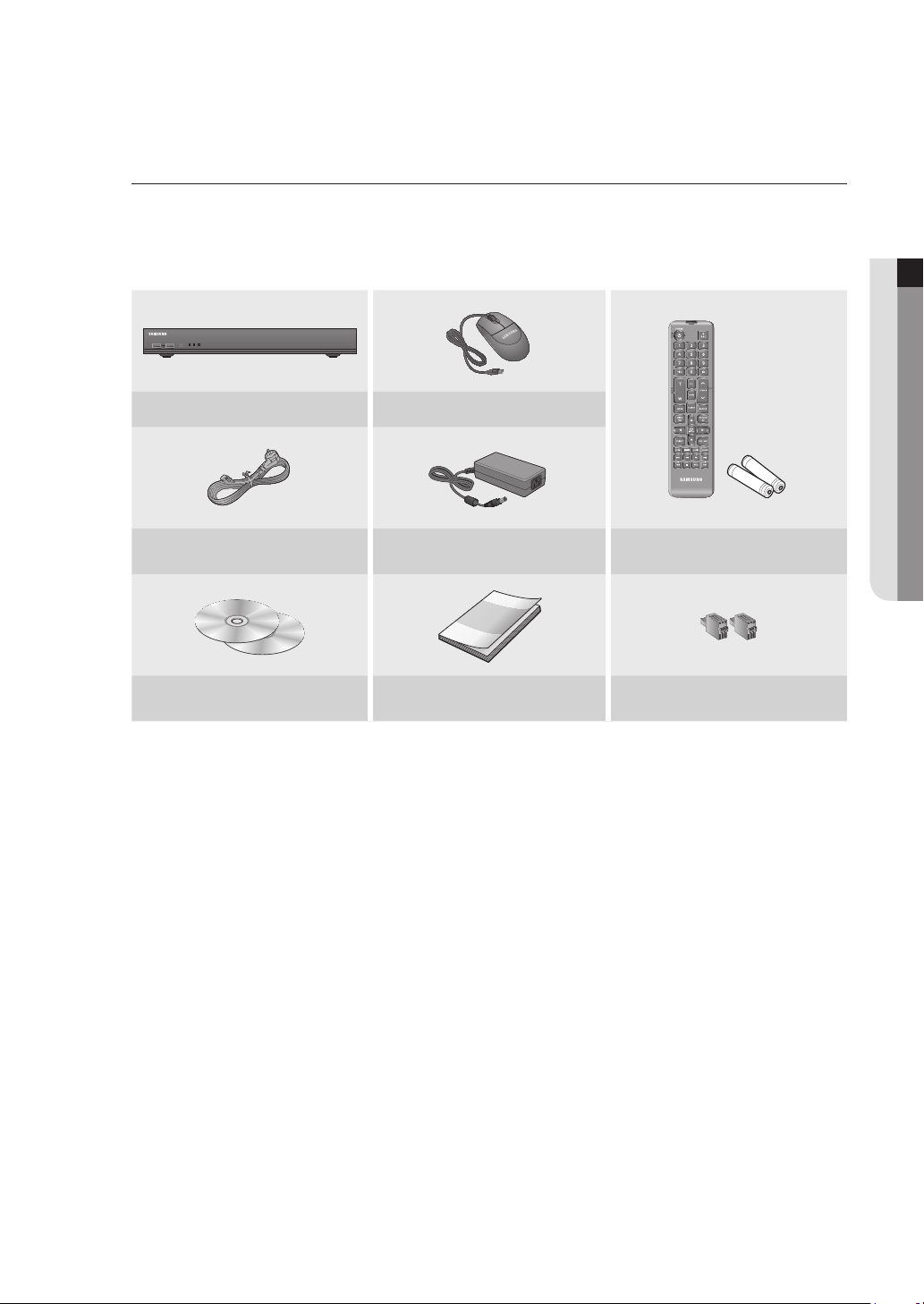
Package Contents
Please unwrap the product, and place the product on a flat place or in the place to be installed.
Please check the following contents are included in addition to the main unit.
SRN-473S
RECALARMPOWER
NVR Mouse
Power Cable Power Adaptor
Network Viewer Software /
User Manual CD
` Two additional screws are provided to install an HDD for models that come without an HDD installed.
M
NETWORK VIDEO RECORDER
User Manual or Quick Manual Terminal block
● OVERVIEW
Remote Control /
Remote Control Battery (AAA)
English _9
overview
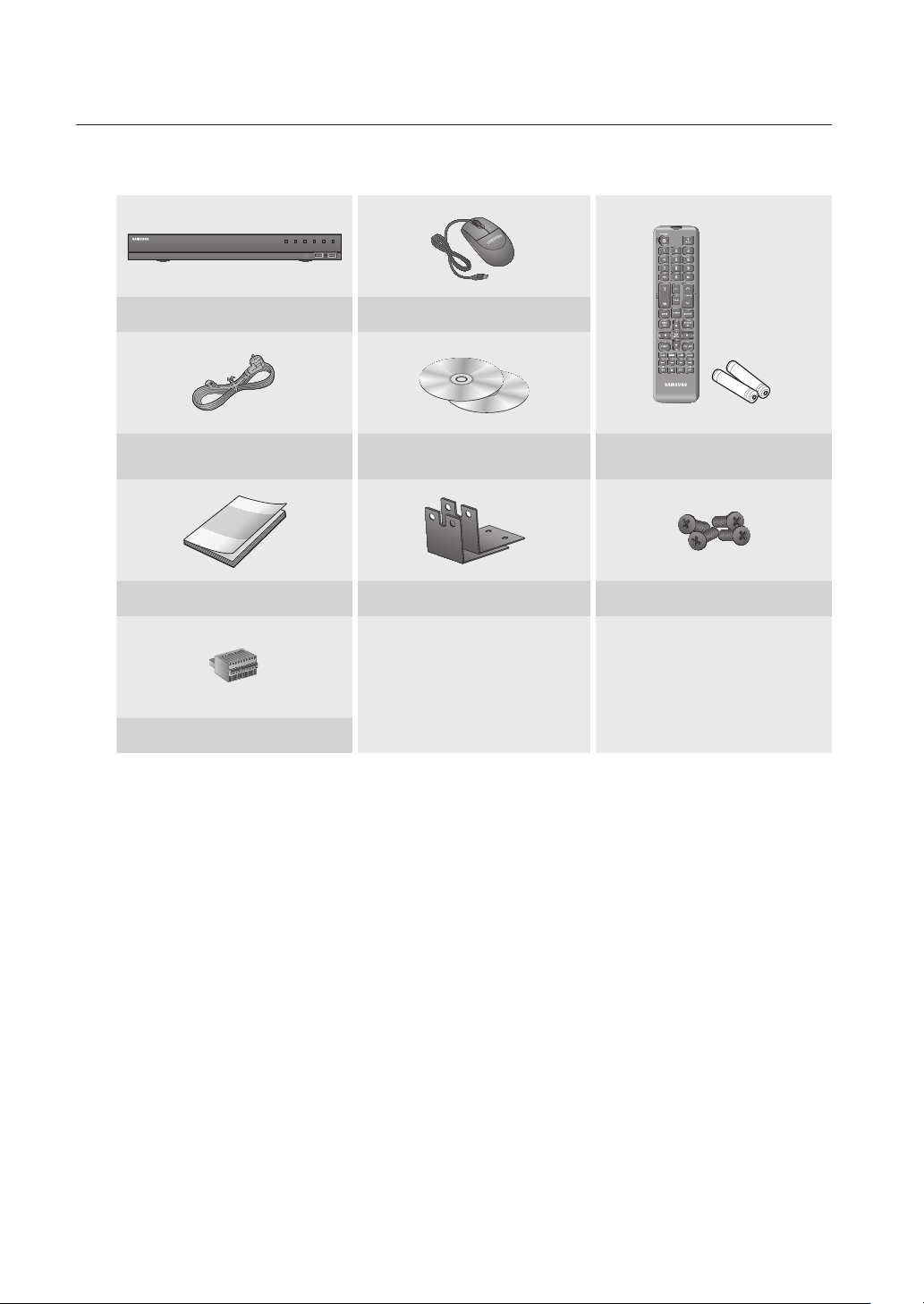
SRN-873S
DV25
NETWORK VIDEO RECORDER
SRN-475S
NVR Mouse
REC HDD ALARM
NETWORK BACKUP
POWER
Power Cable
Network Viewer Software /
User Manual CD
Remote Control /
Remote Control Battery (AAA)
User Manual or Quick Manual Bracket rack Bracket mounting screws
Terminal block
10_ overview
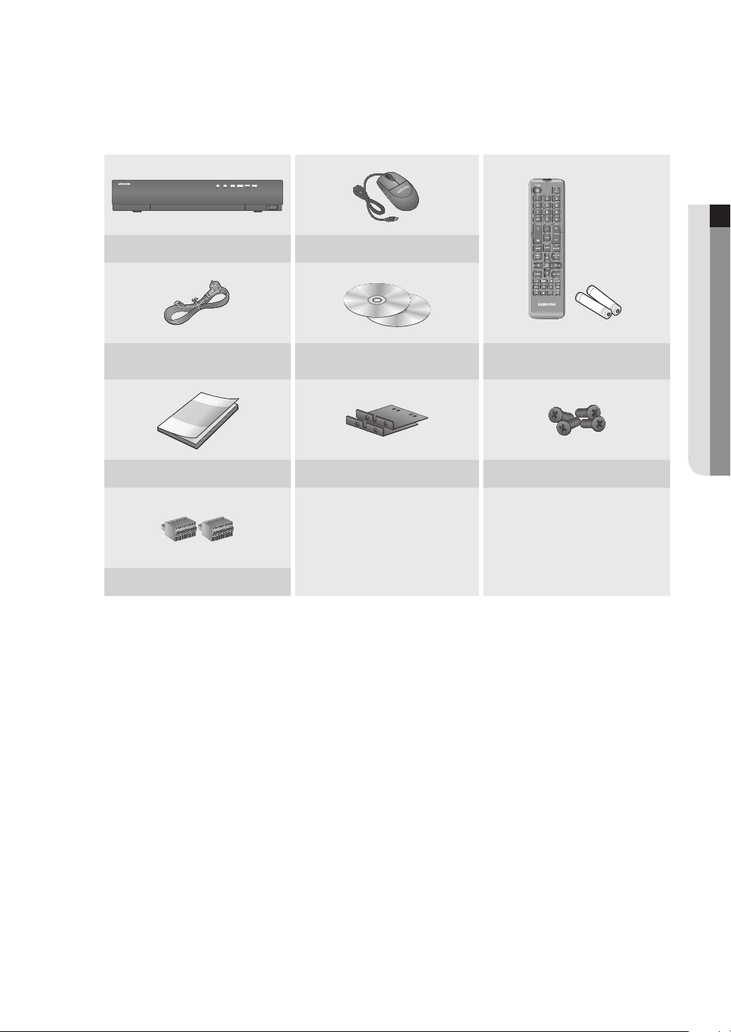
SRN-1673S
NETWORK VIDEO RECORDER
USB
NVR Mouse
Power Cable
Network Viewer Software /
User Manual CD
Remote Control /
Remote Control Battery (AAA)
User Manual or Quick Manual Bracket rack Bracket mounting screws
Terminal block
● OVERVIEW
English _11
overview
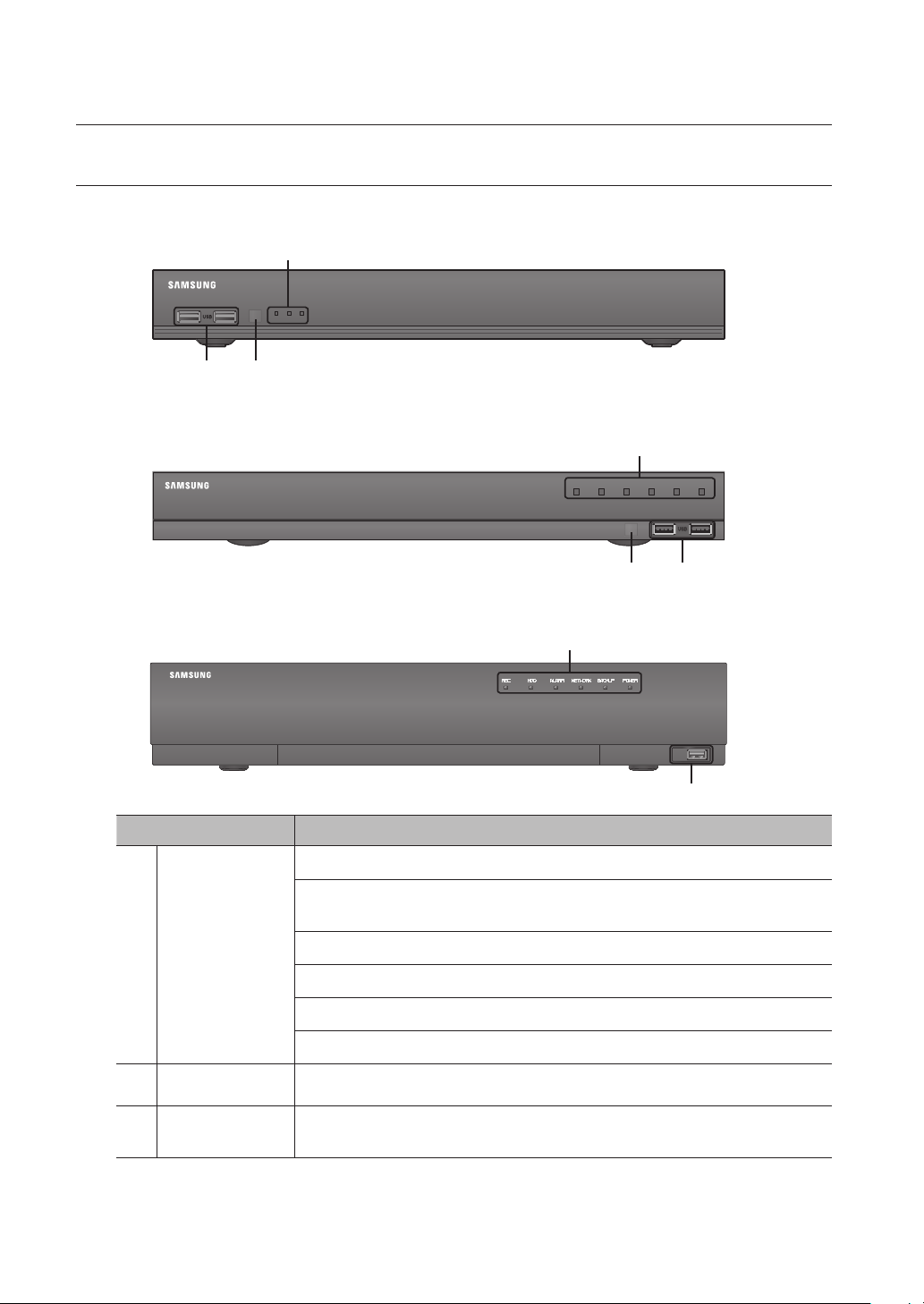
PART NAMES AND FUNCTIONS (FRONT)
SRN-473S
RECALARMPOWER
bac
SRN-873S
NETWORK VIDEO RECORDER
a
NETWORK VIDEO RECORDER
SRN-1673S
NETWORK VIDEO RECORDER
Part Names Functions
LED Indicator
a
DV25
SRN-475S
REC HDD ALARM
NETWORK BACKUP
POWER
bc
a
USB
b
REC : Lights on when recording is in progress.
HDD : Displays the normal access to HDD.
LED turns on when accessing the hard disk.
ALARM : Lights on when an event occurs.
NETWORK : Displays both network connection and data transfer status.
b
c
12_ overview
USB
Remote Reception
System
BACKUP : Displays when Backup is in progress.
POWER : Shows the power ON/OFF status.
Connects the USB devices.
Receive the signal from the remote control.
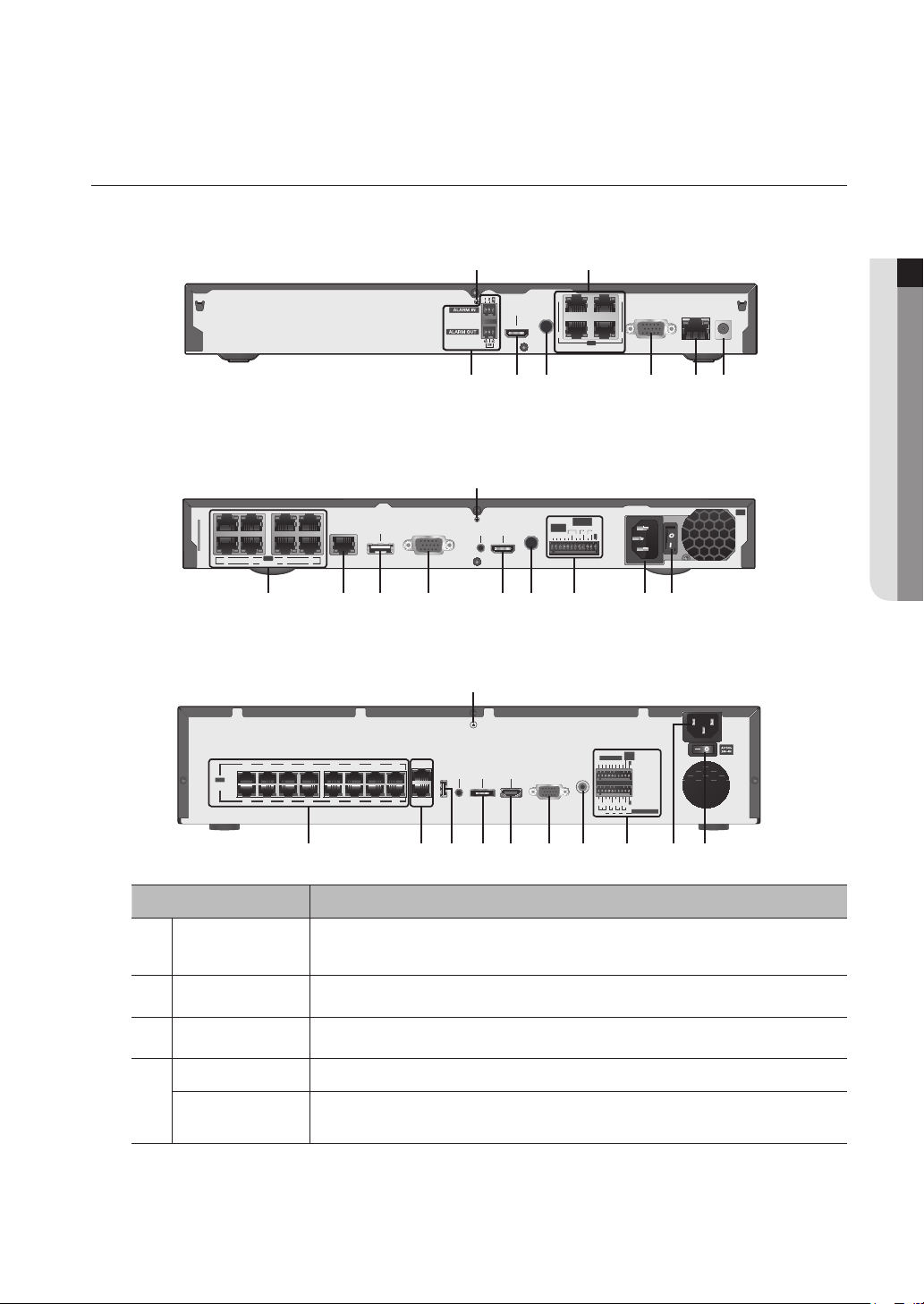
PART NAMES AND FUNCTIONS (REAR)
SRN-473S
SRN-873S
SRN-1673S
1234567
PoE
8
CAMERA
123456789101112131415
PoE
CAMERA
a b
1
AUDIO
HDMI
OUT
2
3
VGA OUT
4
PoE
CAMERA
a
ALARM
OUT
ALARM
AUDIO
1 2 3
VIEWER
eSATA
VGA OUT
HDMICONSOLE
IN
OUT
COM COM COM
1 2 3
4
NCNO NO NO
G
d ej g fb h ci
a
ALARM
RESET
ALARM IN
1 2 3 4 5 6 7 8
NO
NCNO NO NO
COM COM COM COM
1 2 3 4
G
G
ALARM OUT
VIEWER
CONSOLE
16
SWITCH
VGA OUT AUDIO OUTUSB
HDMIeSATA
VIEWER
● OVERVIEW
DC 54V
cdefgh
AC 100
240~IN
b hd k j g e f ic
Part Names Functions
Ground connection
a
PoE (CAMERA)
b
Power
c
VIEWER
d
SWITCH
A terminal to connect a separate ground cable.
` Make sure to add a ground cable in order to use the equipment safely.
Power supply port to connect to a camera.
Terminal to connect power to.
Port used to send video to the web viewer.
Port connected to a camera, and you can access the camera's web viewer to setup detailed
camera settings.
English _13

overview
Part Names Functions
VGA OUT
e
AUDIO OUT
f
HDMI
g
ALARM
h
Power Switch
i
eSATA
j
USB
k
` [CONSOLE] is designed for the service repair purpose only.
M
VGA Video Signal Output Port.
Audio Signal Output Port (RCA jack).
HDMI connector port.
- ALARM IN : Alarm input ports.
SRN-473S : 1~2 CH
SRN-873S : 1~4 CH
SRN-1673S : 1~8 CH
- ALARM OUT : Alarm output ports.
SRN-473S : 1CH
SRN-873S : 1~3 CH
SRN-1673S : 1~4 CH
- ALARM RESET : Alarm Reset port.
` Applicable only to the SRN-1673S model.
Power on/off switch.
Ports used for external storage device connections.
Connects the USB devices.
14_ overview

REMOTE CONTROL
Displays the Exit pop up screen.
Used as the numeric input keys, or displays a single
Runs the digital zoom (x2) function.
Skip Backward (by unit time),
Slow Rewind, Slow Forward,
NUMBER [0~+10]
Displays or ends PTZ.
Displays the search menu.
Changes the screen mode.
Display the live screen menu.
Displays the Preset Setup.
Freezes the screen temporarily.
Skip Forward (by unit time)
POWER
channel.
PTZ
T/W
Zooms in or out.
SEARCH
MODE
MENU
PRESET
FREEZE
ZOOM
REC
Starts or ends the live recording.
ID
Sets the ID of the system.
Select 2 digits from 0 ~ 9 while pressing the ID Key.
SCROLL ,.
Moves the menu scroll.
VIEW
Runs the View function in the PTZ mode.
BACKUP
Displays the Backup Menu.
RETURN
Returns to the previous screen.
Up/Down/Left/Right($%_ +)/ENTER
Moves the cursor up/down/left/right, and runs the
Select Menu.
REC LOCK
Selects the recording lock function.
AUDIO
Turns Audio on/off.
ALARM
Cancels the Alarm.
Move Frame
While paused, moves to the previous/next frame.
● OVERVIEW
FR, STOP, PLAY/PAUSE, FF
English _15

overview
Using the Numeric buttons
CHANNEL 1–9 Press each button between 1 to 9.
CHANNEL 10 Press the [+10] button first, then press the 0 button again within 3 seconds.
CHANNEL 11–16 Press the [+10] button first, then press any number between 1 to 6 within 3 seconds.
Changing the Remote Control ID
Remote control’s ID and NVR’s ID should be matched for proper operation.
1. Press the [ID] button of the remote control and check the ID displayed on the NVR screen.
The factory default ID of the remote control is 00.
2. Enter 2 digits of your selection in order, while pressing the [ID] button of the remote control.
3. When ID input is done, press the [ID] button of the remote control again to check the setting.
` If you want to change the remote control ID to 08: Press 0 and 8 in order while the [ID] button of the remote control is
M
pressed.
For changing the ID of remote device, refer to “Remote Devices”. (Page 85)
16_ overview
installation
Please take note of the followings before using this product.
• Do not use the product outdoor.
• Do not spill water or liquid in the connection part of the product.
• Do not impose the system to excessive shock or force.
• Do not pull out the power plug forcefully.
• Do not disassemble the product on your own.
• Do not exceed the rated input/output range.
• Use a certified power cord only.
• For the product with an input ground, use a grounded power plug.
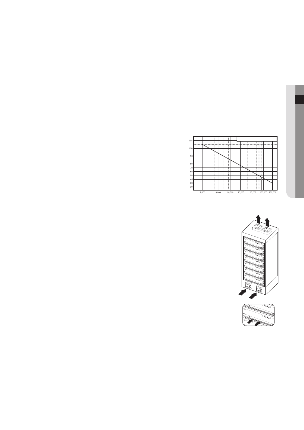
CHECKING THE INSTALLATION ENVIRONMENT
● INSTALLATION
This product is a top-notch security device that is equipped
with a high-capacity HDD and other key circuit boards.
Note that an excessive internal temperature of the product may
cause a system failure or a shortened product life (see the right
figure). Keep in mind the following instructions before installing
the product.
When mounting the product on a rack, comply with the following instructions.
1. Please ensure that the rack inside is not sealed.
2. Please ensure the air is circulated through the inlet/outlet as shown in the picture.
3. If you pile up the prudcts or other rack-mount devices as shown in figure 2, secure room for
ventilation or install a vent.
4. For natural air convection, place the inlet at the bottom of the rack and the outlet on top.
5. It is strongly recommended that a fan motor is installed at the inlet and the outlet for air
circulation. (Please fit a filter at the inlet to screen dust or foreign substances.)
6. Please maintain the temperature inside the rack or surrounding areas between 0°C ~ 40°C
(32°F ~ 104°F) as shown in the figure 1.
Rack Mount Instructions - The following or similar rack-mount instructions are included with
the installation instructions :
A) Elevated Operating Ambient - If installed in a closed or multi-unit rack assembly, the
operating ambient temperature of the rack environment may be greater than room
ambient. Therefore, consideration should be given to installing the equipment in an
environment compatible with the maximum ambient temperature (Tma) specified by the
manufacturer.
B) Reduced Air Flow - Installation of the equipment in a rack should be such that the amount of air flow required
for safe operation of the equipment is not compromised.
C) Mechanical Loading - Mounting of the equipment in the rack should be such that a hazardous condition is
not achieved due to uneven mechanical loading.
D) Circuit Overloading - Consideration should be given to the connection of the equipment to the supply circuit
and the effect that overloading of the circuits might have on overcurrent protection and supply wiring.
Appropriate consideration of equipment nameplate ratings should be used when addressing this concern.
E) Reliable Earthing - Reliable earthing of rack-mounted equipment should be maintained. Particular attention should
be given to supply connections other than direct connections to the branch circuit (e.g. use of power strips).
Temperature
Unit: ºC
One Year: 24HR X 365 DAY =8,760 HR
Life (Unit: HOURS)
[Figure 1]
[Figure 2]
English _17
installation
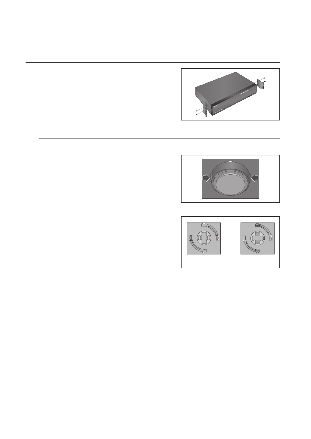
RACK INSTALLATION
Install the Bracket-Rack as shown in the figure, and then fasten the
screws on both sides (2 screws on each side).
` Fix the screws not to be loosened by vibrations.
Cautions when Installing in the Rack
To install multiple NVRs in the rack, make sure to separate the FOOT at the bottom of each NVR.
1. There are four FOOTs at the bottom of a NVR.
Press the projected parts at both-ends of each “FOOT” and
turn it counterclockwise.
2. “FOOT” is separated from the main body when it is turned
to the end of fastening groove.
<Separation> <Installation>
18_ installation

HDD ADDITION
Make sure to unplug the power cord from the wall outlet to prevent possible electric shock, injury or product damage.
Please consult your provider for further information on HDD installation since improper installation or settings may
damage the product.
` Number of HDDs supported : SRN-473S : max 1
SRN-873S : max 2
SRN-1673S : max 4 can be added.
` Make sure to unplug the power cord from the wall outlet before proceeding with the installation.
` Cautions for data loss (HDD care)
J
Please pay attention so that the data inside the HDD is not damaged.
Before adding a HDD, please check the compatibility with this product.
HDD is vulnerable to malfunction due to its sensitive nature especially against shock when operating.
Please ensure that the HDD is free from such shock.
We are not liable for any damage to the HDD incurred by user's carelessness or miss use.
` Cases might cause damage to HDD or recorded data
To minimize the risk of data loss from a damaged HDD, please backup data as often as possible.
If exposed to shock when disassembling or installing, data stored in the hard disk may be damaged.
A sudden power failure or turning off the product while in HDD operation may damage the hard disk drive.
HDD or files stored inside may be damaged if the main body is moved or impacted during the HDD operation.
Cautions when installing a HDD
● INSTALLATION
1. Do not apply excessive force to the HDD.
2. Pay attention so as not to lose the disassembly screws or accessories.
` If the screws or accessories are not put together correctly, the product may breakdown or not operate properly.
3. Please check the HDD compatibility before adding a HDD.
` Please contact your nearest dealer to obtain the list of compatible devices.
English _19
installation
Installing the HDD
` If the installed HDD had been used with other devices, it will be automatically formatted.
J
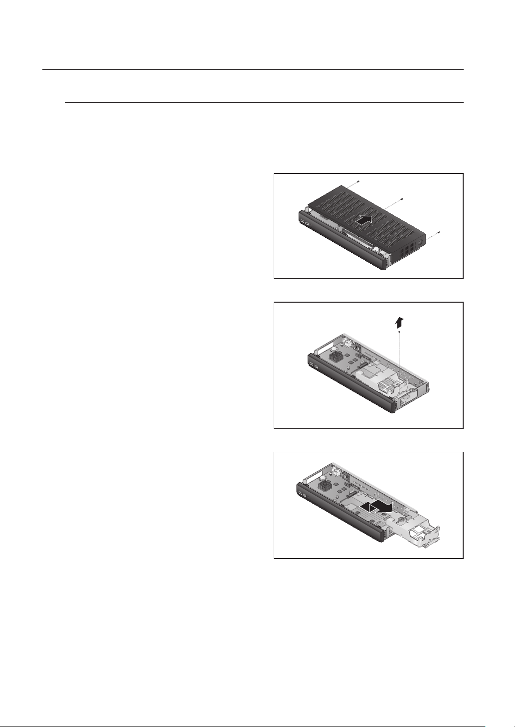
How to install an HDD in SRN-473S
1. After unscrewing, push back and remove the cover.
2. Loosen a setscrew of the bracket.
3. Push the bracket in the direction of the arrow on the
board and remove it.
20_ installation
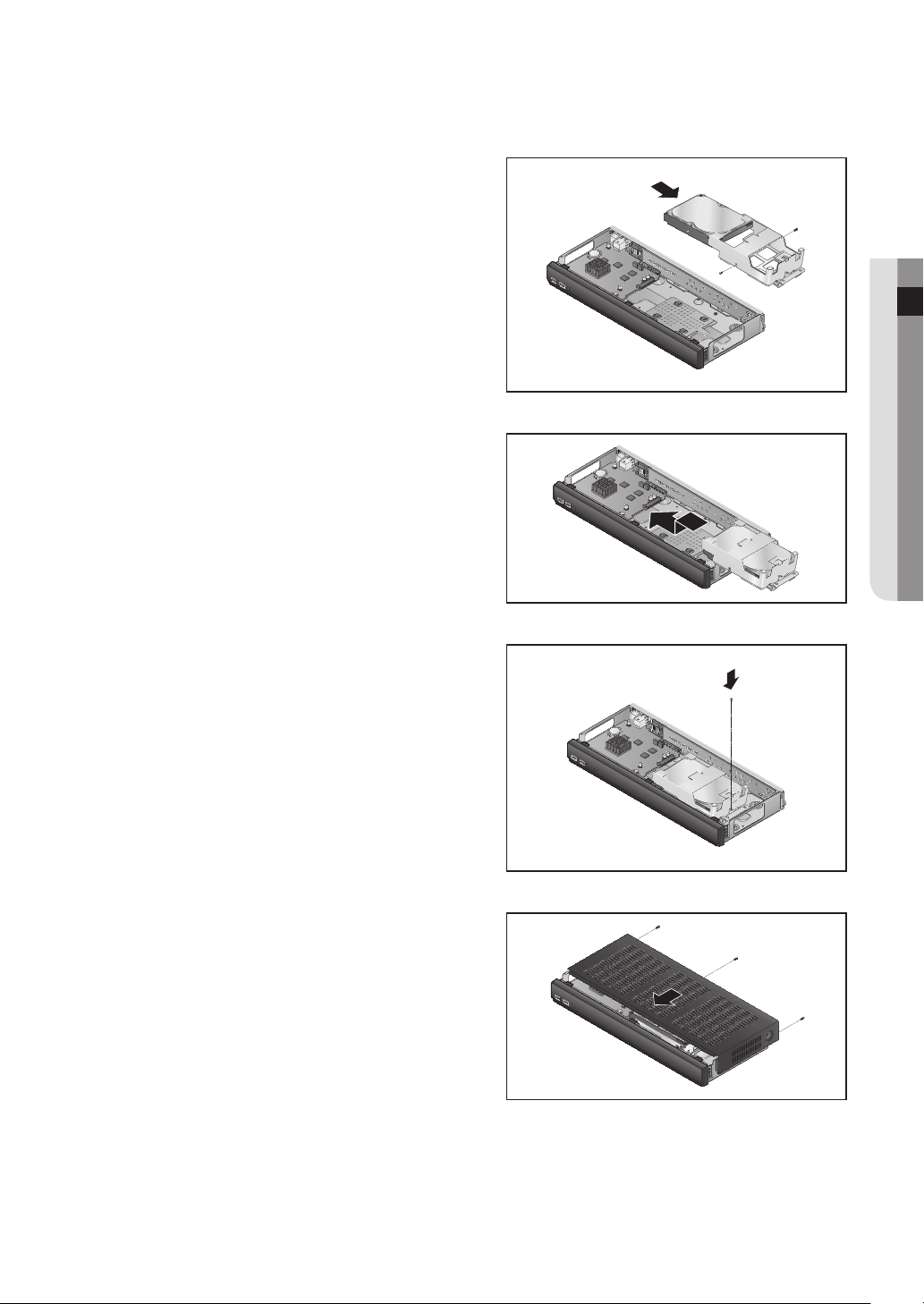
4. After inserting the HDD into the bracket, tighten the
left and right screws to fix it.
5. Locate the bracket with the HDD installed in a
groove of the case, push it in the arrow direction and
connect a power data port on the board.
6. Tighten a setscrew of the bracket.
● INSTALLATION
7. Close the cover, and tighten a setscrew in the back.
English _21
installation
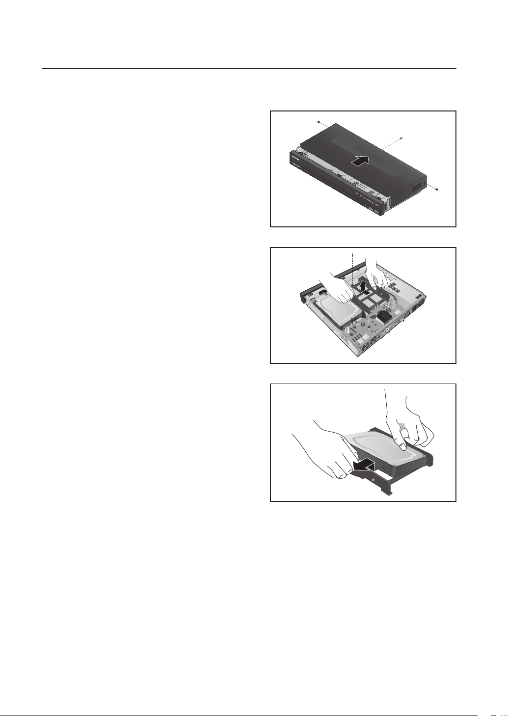
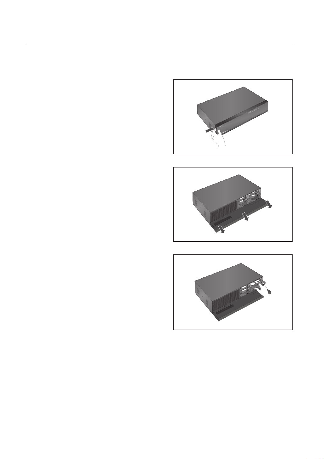
How to install an HDD in SRN-873S
1. First of all, loosen the screws in the left, right, and
back of the case, and remove the cover.
2. Loosen a screw from the HDD bracket and remove
the bracket.
` While applying pressure to both side end grips of the bracket,
pull them forward to remove the HDD bracket from the main
body.
3
ALARM
G
OUT
2
NO
1
NO
NCNO
COM COM COM
IN
ALARM
4
23
1
CONSOLE
eSATA
VIEWER
7
8
5
6
PoE
CAMERA
3
4
1
2
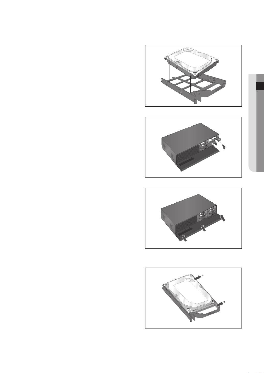
3. After aligning and inserting one side of the HDD to
the bracket, open the other side bracket wide and
insert the HDD between them.
` Align a hole in the bracket with a screw hole in the HDD to fix
them.
22_ installation
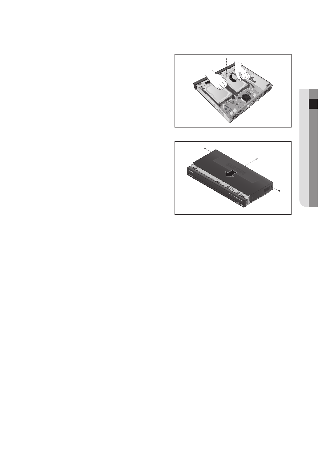
4. Push the bracket with the HDD installed and tighten
the screws to fix it.
5. Close the cover and tighten the screws to fix it.
3
ALARM
G
OUT
2
NO
1
NO
NCNO
COM COM COM
IN
ALARM
4
23
1
CONSOLE
eSATA
VIEWER
7
8
5
6
PoE
CAMERA
3
4
1
2
● INSTALLATION
English _23
installation
How to install an HDD in SRN-1673S
• How to open the front cover and install an HDD
1. Pull open the front cover.
2. Open the front cover and check the HDD installation
bracket.
` Release the USB connection before opening the front
J
cover to prevent damage to the USB port.
3. Push the latch to the right and remove the HDD
bracket.
` Take care not to scratch your hands when removing the
J
HDD bracket.
24_ installation
4. Align and insert HDD into the bracket home. After
inserting one side, push and insert the other side
slightly.
5. Align the bracket with the HDD installed with the
enclosure latch, and push the bracket in the direction
of the board.
` Push it until you hear the latch lock sound. If the HDD is
J
not completely connected, it may be detected.
6. Push the front cover upwards and close it.
● INSTALLATION
• How to exchange an installed HDD
1. Open a bracket wide in the direction of the arrow and
remove the holder from the HDD.
2. Open the other bracket wide and remove it from the
holder.
` The procedure after HDD exchange is the same as the
M
procedure for "Installing the HDD".
English _25
connecting with other device
HDMIeSATA VGA OUT AUDIO OUTUSB
1
2
3
4
5
6
7
8
9
10
11
12
13
14
15
16
12 3 4 56 7 8
NO
COM COM COMCOM
NCNO NO NO
1 2 3 4
ALARM IN
PoE
ALARM OUT
G
G
ALARM
RESET
CONSOLE
VIEWER
CAMERA
SWITCH
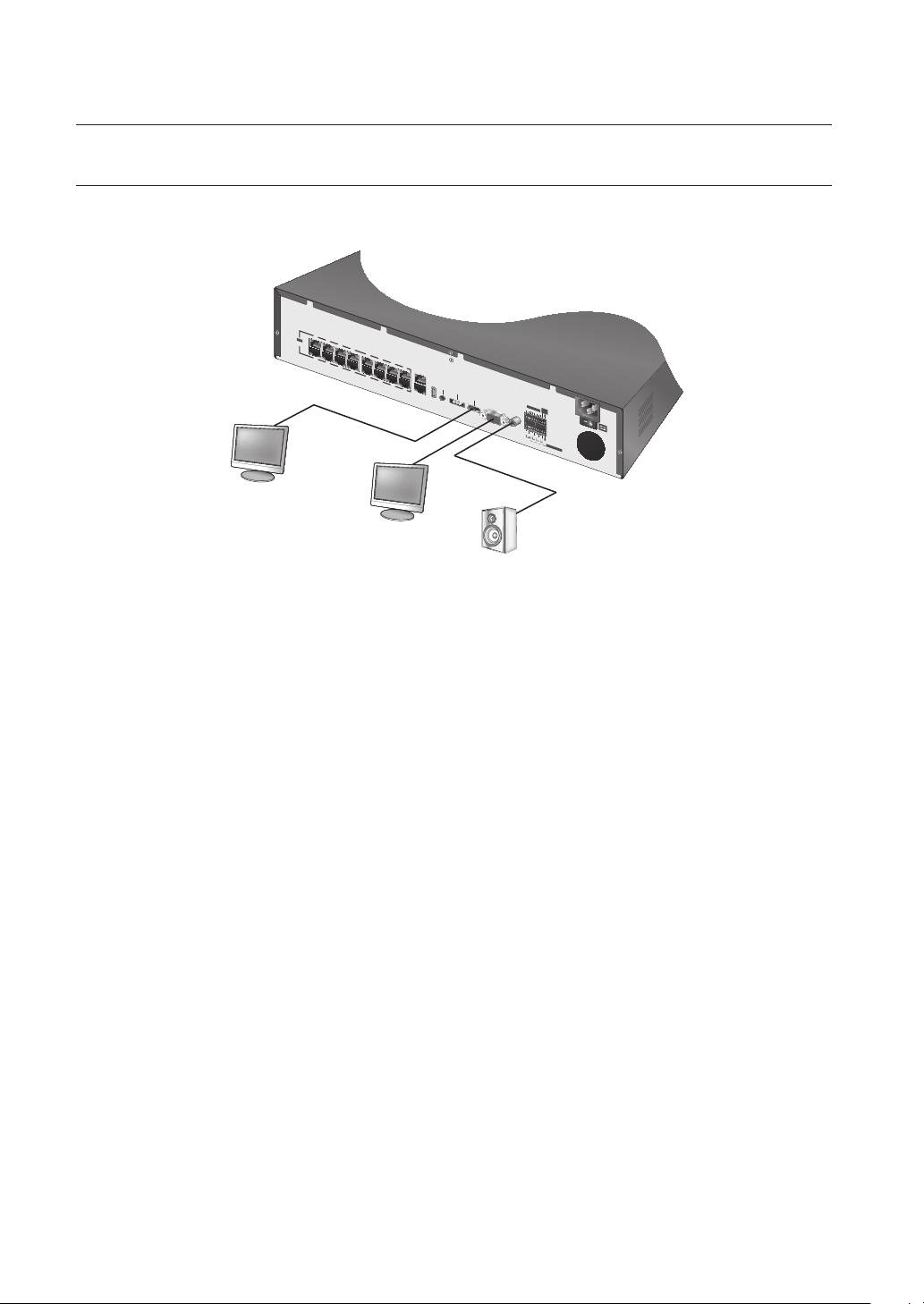
CONNECTING TO AN EXTERNAL DEVICE
` The following figures are based on Model SRN-1673S.
M
HDMI OUT
VIDEO OUT
(VGA)
` Unrated or improper power source may cause damage to the system. Ensure that you use only the rated power source
J
before pressing the POWER button.
AUDIO OUT
26_ connecting with other device
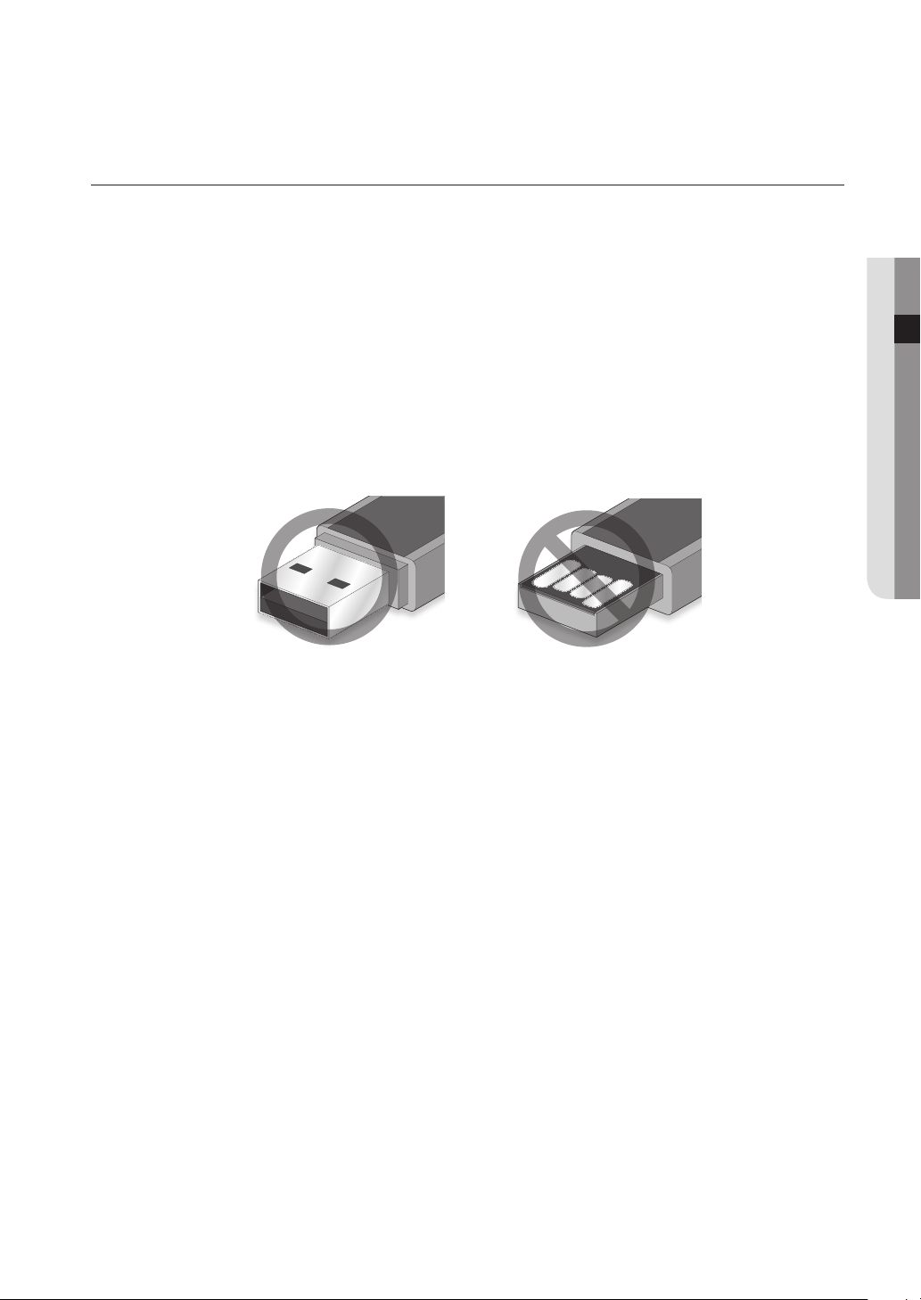
CONNECTING THE USB
1. On the front of the product, there is a USB port.
2. USB HDD, memory, or a mouse can be connected to USB ports.
If a USB HDD is connected to the system, recognition and settings are available in "Setup > Device > Storage
3.
Device". (Page 83)
4. The product supports hot plugging function that enables connecting/disconnecting USB devices while in
operating the system.
` If you use the USB device for Backup purposes, format it with FAT32 on PC if it is not formatted on the NVR.
J
` Some USB devices may fail to function properly due to compatibility issue, please check the device before using.
` Only USB storage devices that comply with the standards (having a metal cover) are guaranteed for data transfer. In case if
the USB device’s electric contacts have been worn out, data transfer between the devices may not properly function.
● CONNECTING WITH OTHER DEVICE
English _27
connecting with other device
VIEWER
1
2
3
4
PoE
CAMERA
HDMI
VGA OUT
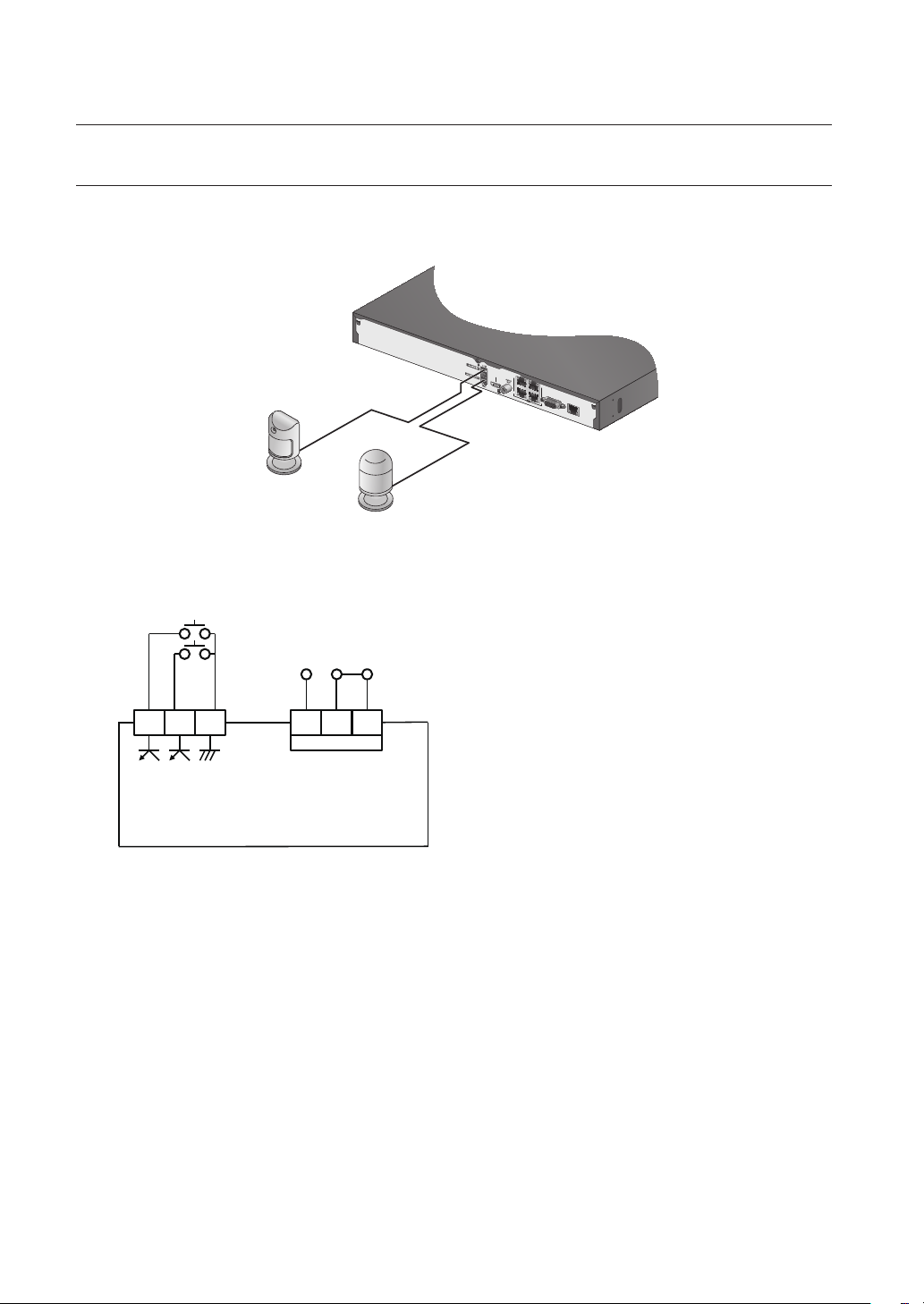
CONNECTING THE ALARM INPUT/OUTPUT
The Alarm In/Out port at the back is composed of the following.
SRN-473S
Sensors
Alarm
• ALARM IN 1 ~ 2 : Alarm Input Port
• ALARM OUT 1 : Alarm Output Port
ALARM IN
(
5mA sink
N.O C N.C1 2 G
1
ALARM OUT
)
(
30VDC 2A,
125VAC 0.5A MAX
)
28_ connecting with other device
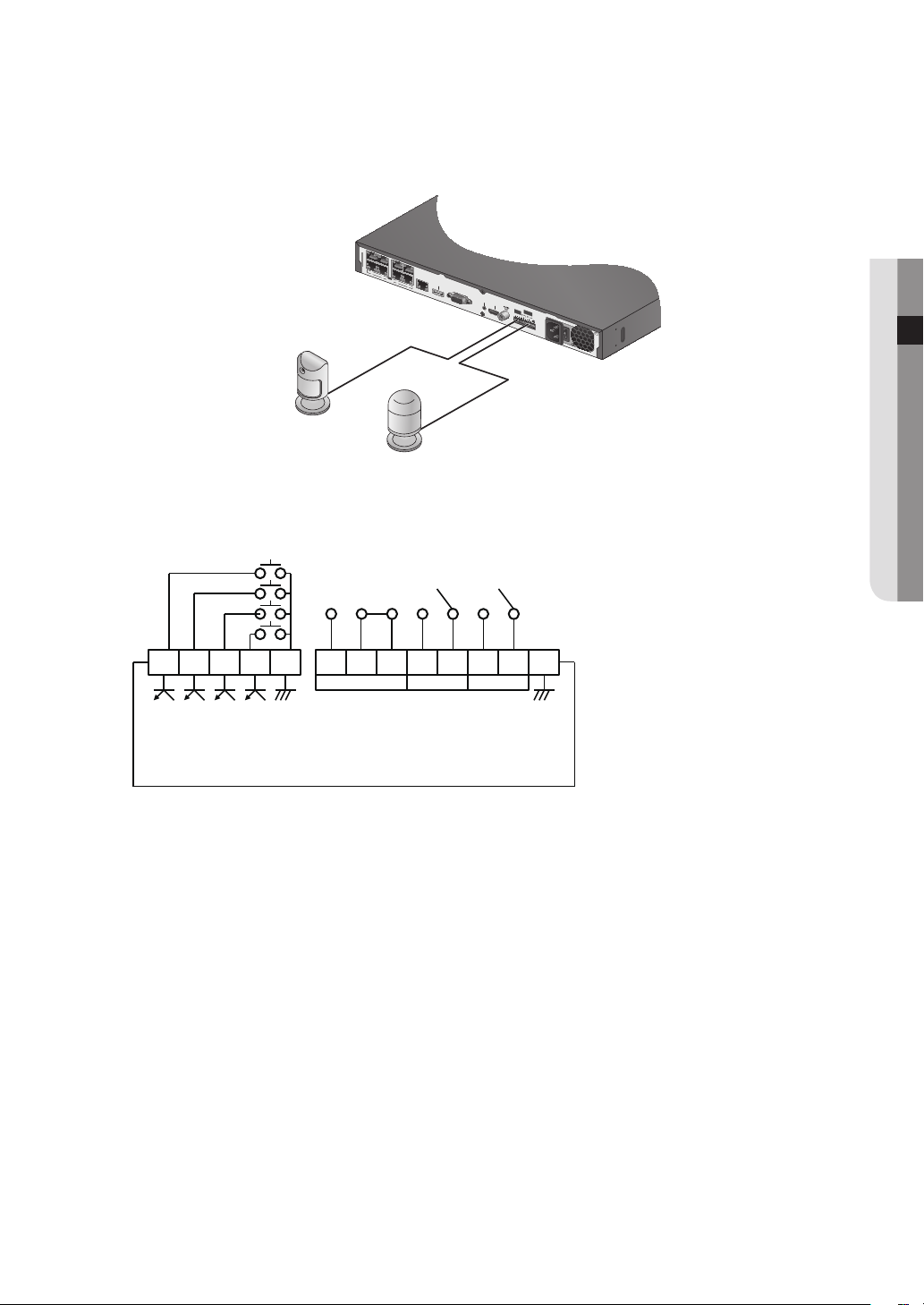
SRN-873S
G
12 3
1 2 3
4
NCNO NO NO
COM COM COM
ALARM
OUT
ALARM
IN
VGA OUT
HDMI
CONSOLE
VIEWER
eSATA
PoE
CAMERA
1
2
3
4
5
6
7
8
Sensors
• ALARM IN 1 ~ 4 : Alarm Input Port
• ALARM OUT 1 ~ 3 : Alarm Output Port
N.O C N.C N.O C N.O C G1 2 3 4 G
1 2 3
● CONNECTING WITH OTHER DEVICE
Alarm
ALARM IN
(
5mA sink
)
ALARM OUT
(
30VDC 2A,
125VAC 0.5A MAX
)
English _29
connecting with other device
HDMIeSATA VGA OUT AUDIO OUTUSB
1
2
3
4
5
6
7
8
9
10
11
12
13
14
15
16
12 3 4 56 7 8
NO
COM COM COMCOM
NCNO NO NO
1 2 3 4
ALARM IN
PoE
ALARM OUT
G
G
ALARM
RESET
CONSOLE
VIEWER
CAMERA
SWITCH
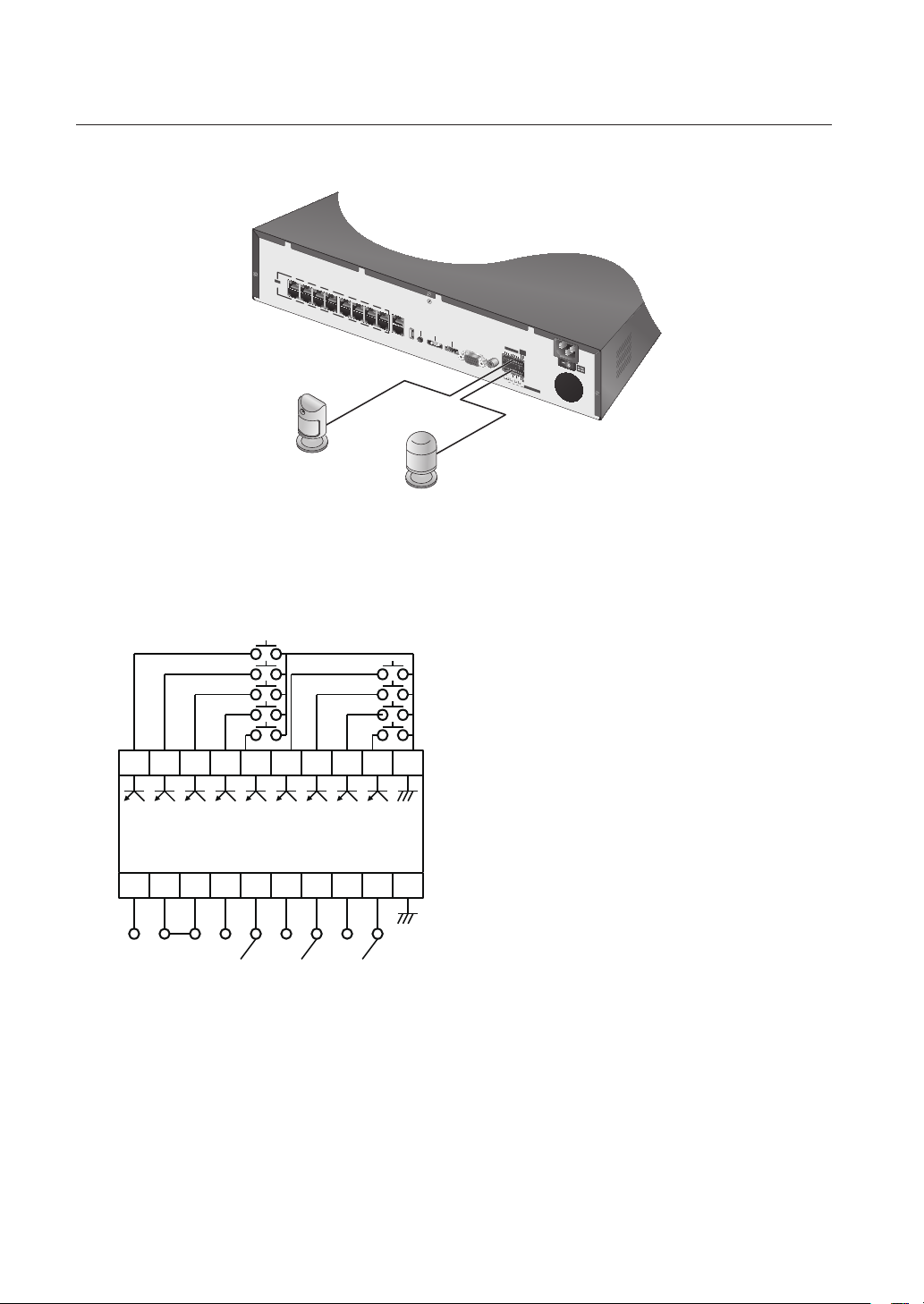
SRN-1673S
Sensors
Alarm
• ALARM IN 1 ~ 8 : Alarm Input Port
• ALARM RESET : On receiving an Alarm Reset signal, the system cancels the current Alarm Input and
resumes sensing.
• ALARM OUT 1 ~ 4 : Alarm Output Port
1 2 3 4 5 6 7 8 A.R G
N.O C N.C N.O C N.O C N.O C G
30_ connecting with other device
ALARM IN
(
5mA sink
)
ALARM OUT
(
30VDC 2A, 125VAC 0.5A MAX
)
 Loading...