

Page 1

Network Camera
User Manual
SNC-B5399(P)
imagine the possibilities
Thanks you for purchasing this Samsung product.
To receive a more complete service, please visit
our website
www.samsungsecurity.com
RoHS compliant
Our product complies with “The Restriction Of the use of certain Hazardous Substances in electrical
and electronic equipment”, and we do not use the 6 hazardous materials- Cadmium (Cd), Lead
(Pb), Mercury (Hg), Hexavalent Chromium (Cr
Diphenyl Ethers (PBDEs)- in our products.
+6
), Poly Brominated Biphenyls (PBBs), Poly Brominated
Page 2
overview
CAUTION
RISK OF ELECTRIC SHOCK.
DO NOT OPEN
CAUTION: TO REDUCE THE RISK OF ELECTRIC SHOCK, DO NOT REMOVE COVER (OR BACK) NO USER
SERVICEABLE PARTS INSIDE. REFER SERVICING TO QUALIFIED SERVICE PERSONNEL.
This symbol indicates that dangerous voltage consisting a risk of
electric shock is present within this unit.
This symbol indicates that there are important operating and
maintenance instructions in the literature accompanying this unit.
WARNING
y
To reduce the risk of fi re or electric shock, do not expose this appliance to rain or
moisture.
y
To prevent injury, this apparatus must be securely attached to the fl oor/wall in accordance
with the installation instructions.
y
If this power supply is used at 24V ac, a suitable plug adapter should be used.
y
The camera is to be only connected to PoE networks without routing to the outside plant.
WARNING
Be sure to use only the standard adapter that is specifi ed in the specifi cation sheet.
1.
Using any other adapter could cause fi re, electrical shock, or damage to the product.
Incorrectly connecting the power supply or replacing battery may cause explosion, fi re,
2.
electric shock, or damage to the product.
Do not connect multiple cameras to a single adapter. Exceeding the capacity may cause
3.
abnormal heat generation or fi re.
Securely plug the power cord into the power receptacle. Insecure connection may
4.
cause fi re.
When installing the camera, fasten it securely and fi rmly. The fall of camera may cause
5.
personal injury.
Do not place conductive objects (e.g. screwdrivers, coins, metal parts, etc.) or
6.
containers fi lled with water on top of the camera. Doing so may cause personal injury
due to fi re, electric shock, or falling objects.
2_ overview
Page 3

Do not install the unit in humid, dusty, or sooty locations. Doing so may cause fi re or
7.
electric shock.
If any unusual smells or smoke come from the unit, stop using the product. In such
8.
case, immediately disconnect the power source and contact the service center.
Continued use in such a condition may cause fi re or electric shock.
If this product fails to operate normally, contact the nearest service center. Never
9.
disassemble or modify this product in any way. (SAMSUNG is not liable for problems
caused by unauthorized modifi cations or attempted repair.)
When cleaning, do not spray water directly onto parts of the product. Doing so may
10.
cause fi re or electric shock
Do not expose the product to the direct airfl ow from an air conditioner.
11.
Otherwise, it may cause moisture condensation inside the Clear Dome due to
temperature difference between internal and external of the dome camera.
If you install this product in a low-temp area such as inside a cold store, you must seal
12.
up the wiring pipe with silicon, so that the external air can not fl ow inside the housing.
Otherwise, external high, humid air may fl ow inside the housing, pooling moisture or
vapor inside the product due to a difference between internal and external temperature.
● OVERVIEW
English _3
Page 4

overview
CAUTION
Do not drop objects on the product or apply strong blows to it. Keep away from a
1.
location subject to excessive vibration or magnetic interference.
2.
Do not install in a location subject to high temperature (over 50°C), low temperature
(below -10°C), or high humidity. Doing so may cause fi re or electric shock.
3.
If you want to relocate the already installed product, be sure to turn off the power and
then move or reinstall it.
4.
Remove the power plug from the outlet when there is a lighting storm. Neglecting to do
so may cause fi re or damage to the product.
5.
Keep out of direct sunlight and heat radiation sources. It may cause fi re.
6.
Install it in a place with good ventilation.
7.
Avoid aiming the camera directly towards extremely bright objects such as sun, as this
may damage the CCD image sensor.
8.
Apparatus shall not be exposed to dripping or splashing and no objects fi lled with
liquids, such as vases, shall be placed on the apparatus.
9.
The Mains plug is used as a disconnect device and shall stay readily operable at any
time.
10.
When using the camera outdoors, moisture may occur inside the camera due
to temperature difference between indoors and outdoors. For this reason, it is
recommended to install the camera indoors. For outdoor use, use the camera with builtin fan and heater.
4_ overview
Page 5

FCC STATEMENT
This device complies with part 15 of the FCC Rules. Operation is subject to the following two
conditions :
1) This device may not cause harmful interference, and
2) This device must accept any interference received including interference that may cause
undesired operation.
Caution
This equipment has been tested and found to comply with the limits for a Class A
digital device, pursuant to part 15 of FCC Rules. These limits are designed to provide
reasonable protection against harmful interference when the equipment is operated in a
commercial environment.
This equipment generates, uses, and can radiate radio frequency energy and, if not
installed and used in accordance with the instruction manual, may cause harmful
interference to radio communications. Operation of this equipment in a residential area
is likely to cause harmful interference in which case the user will be required to correct
the interference at his own expense.
IC Compliance Notice
This Class A digital apparatus meets all requirements of the Canadian
Interference.-Causing Equipment Regulations of ICES-003.
● OVERVIEW
English _5
Page 6

overview
IMPORTANT SAFETY INSTRUCTIONS
Read these instructions.
1.
Keep these instructions.
2.
Heed all warnings.
3.
Follow all instructions.
4.
Do not use this apparatus near water.
5.
Clean only with dry cloth.
6.
Do not block any ventilation openings. Install in accordance with the manufacturer’s
7.
instructions.
Do not install near any heat sources such as radiators, heat registers, or other apparatus
8.
(including amplifi ers) that produce heat.
Do not defeat the safety purpose of the polarized or grounding-type plug.
9.
A polarized plug has two blades with one wider than the other. A grounding type plug
has two blades and a third grounding prong. The wide blade or the third prong is
provided for your safety. If the provided plug does not fi t into your outlet, consult an
electrician for replacement of the obsolete outlet.
Protect the power cord from being walked on or pinched particularly at plugs,
10.
convenience receptacles, and the point where they exit from the apparatus.
Only use attachments/accessories specifi ed by the manufacturer.
11.
Use only with the cart, stand, tripod, bracket, or table specifi ed by
12.
the manufacturer, or sold with the apparatus. When a cart is used,
use caution when moving the cart/apparatus combination to avoid
injury from tip-over.
Unplug this apparatus during lightning storms or when unused for
13.
long periods of time.
Refer all servicing to qualifi ed service personnel. Servicing is required when the
14.
apparatus has been damaged in any way, such as powersupply cord or plug is
damaged, liquid has been spilled or objects have fallen into the apparatus, the apparatus
has been exposed to rain or moisture, does not operate normally, or has been dropped.
6_ overview
Apparatus shall not be exposed to dripping or splashing and no objects
filled with liquids, such as vases, shall be placed on the apparatus
Page 7

CONTENTS
OVERVIEW
2
INSTALLATION &
CONNECTION
14
CAMERA SETUP
27
NETWORK CONNECTION
AND SETUP
36
6 Important Safety Instructions
9 Product Features
9 Recommended PC Specifi cations
10 What’s Included
11 At a Glance
14 Disassembling
15 Inserting/Removing an SD
Memory Card
16 Memory Card Information (not
included)
17 Connecting with other Device
21 Installation
21 Optional Accessories for
Installation
27 How to use the menu key
28 Main Menu
28 Profi le
29 Camera Setup
33 Privacy Zone
34 Others
35 System Info
35 Language
36 Connecting the Camera to an
IP Router with the xDSL/Cable
Modem
37 Connecting the Camera to
an IP Router with Local Area
Networking
38 Connecting the Camera Directly
to a DHCP-Based xDSL/Cable
Modem
39 Connecting the Camera Directly
to Local Area Networking
40 IP Address Setup
41 Static IP Setup
44 Dynamic IP Setup
45 Port Range Forward (Port
Mapping) Setup
46 Connecting to the camera from a
shared local PC
46 Connecting to the camera from a
remote PC via the Internet
● OVERVIEW
English _7
Page 8

overview
WEB VIEWER
47
SETUP SCREEN
55
APPENDIX
73
47 Connecting to the camera
48 Login
49 Installing ActiveX
50 Using the Live Screen
51 Backup
54 Using the SD Search Viewer
Screen
55 Accessing the Setup screen
55 Default Setup
60 System Setup
64 Overlay Setup
65 Event Setup
72 Network Setup
73 Profi le
74 Terminology
76 Specifi cations
80 Frame Rate (NTSC)
86 Frame Rate (PAL)
92 Troubleshooting
8_ overview
Page 9

PRODUCT FEATURES
y
Support various communication protocols
Supports TCP/IP, UDP, RTP/RTSP, SMTP for email, and FTP protocols as well as various
internet protocols such as ARP, HTTP, HTTPS and DHCP.
y
Web Browser-based Monitoring
Using the Internet web browser to display the image in a local network environment.
y
Automatic Local IP Setup
Even a network novice can install it with minimum operations.
y
Alarm
If an alarm sensor is connected and it detects a motion, a message is sent to the
registered address via FTP/email (SMTP) or stored in the SD memory card, or an alarm
will signal to the alarm out terminal.
y
Intelligent Video Analysis
If an event rule is defi ned for the video analysis and it detects a motion in the confi gured rule
area, a message is sent to the registered address via FTP/email (SMTP) or stored in the SD
memory card, or an alarm will signal to the alarm out terminal.
PRECAUTIONS – INSTALLATION AND USE
y
Do not bend or drop the SD memory card.
y
Do not store or use the SD memory card in a high temperature, high humidity or dusty place.
y
Be careful not to apply foreign substances on the terminals of SD memory card.
y
In case of cleaning terminals, wipe gently with a soft cloth.
y
Before ejecting the SD memory card, release the checkbox <SD Card Record> in
<Alarm image> and press [Apply] button. (page 67)
y
If SD memory card have reached its lifespan, no data will be saved.
In this case, purchase a new one and replace the SD memory card.
RECOMMENDED PC SPECIFICATIONS
y
CPU : Pentium4 / 2.4GHz or higher
y
Operating System : Windows XP(Service
Pack2, Service Pack3) / Windows Vista
y
Resolution : 1024X768 pixels or higher
y
RAM : 512MB or higher
y
Web Browser : Internet Explorer 6.0 or
higher
y
Video Card : Radeon, Nvidia
y
Video Memory: 128MB
y
DirectX 8.1 or higher
● OVERVIEW
Compatible IP Routers
y
Linksys / D-Link / Netgear
Compatible PoE Switches
y
Linksys SRW224G4P / D-Link DES-1316 / SMC SMCPWR-INJ3
English _9
Page 10
overview
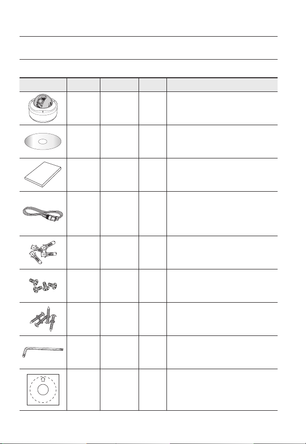
WHAT’S INCLUDED
Please check if your camera and accessories are all included in the product package.
Image Part name Standard Quantity Usage
Camera SNC-B5399 1
User Manual/
CD
IP INSTALLER
S/W
1
10_ overview
User
Manual
Cable for
test monitor
connection
Plastic
Anchor
Fixing
Screws
Tapping
Screws
L-wrench TORX T-20 1
Template ART PAPER 1 Guiding template for the installation
HUD 5 4
BH, M4 x L8,
SILVER
TH, M4xL30.
BLACK +O RING
1
Used to connect to a monitor for camera
operation test.
1
For connecting to a surveillance monitor, use
BNC cable.
Used to fix the screws, for installation Insert
the anchor into a drilled hole (to reinforce the
strength).
Used when installing the case on the ceiling,
4
with pipe or wall mount. Used to stop up a hole.
4 Used for ceiling and wall installations
Used for assembling / disassembling the dome
cover.
Page 11
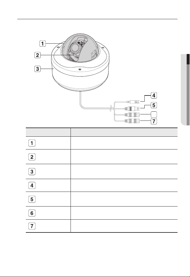
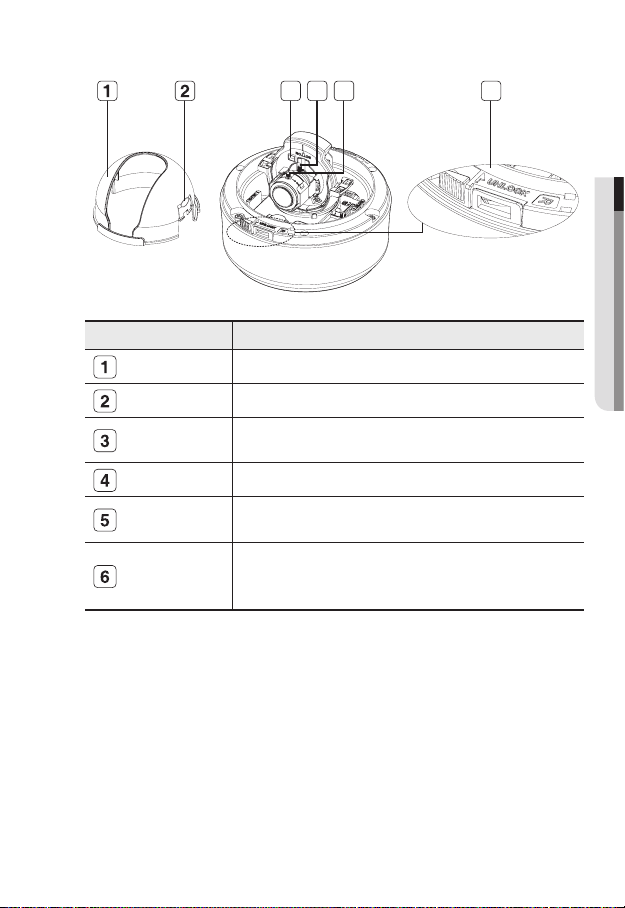
AT A GLANCE
Appearance
Item Description
Dome Cover Dome cover for the lens and unit protection.
● OVERVIEW
6
Heater
Main unit Main unit includes the lens, switch board, PCB boards and screws.
Power Port Used to plug the power cable.
Video Out Jack
Audio In Jack Used to connect to a microphone.
Audio Out Jack Used to connect to speakers.
Wipe out a dirty surface of the lens softly with a lens tissue or cloth to which you have applied
M
ethanol.
Do not touch the unit since it is hot when the heater is operating.
Operates if ambient temperature drops below 5°C, for defrosting the dome
cover.
Connects to the video input terminal of a monitor, which outputs the video
signal from the camera.
English _11
Page 12
overview
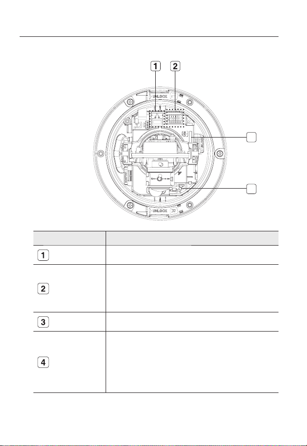
Inside
Item Description
Network Port Used to connect a PoE or LAN cable.
Alarm In / Out
terminals
SD Memory Card
Compartment
Reset Button
3
4
Alarm in/out terminals can be configured as follows:
- ALARM IN : Terminal for Alarm Input.
- ALARM OUT : Terminal for Alarm Output.
- GND : Grounding terminal.
Compartment for the SD memory card.
Resets the camera settings.
Press the button for about 3 seconds, and the system indicator turns off and
will restart.
Resetting the camera requires reconfiguration of network settings (IP
J
address, subnet mask, gateway address etc.) using the IP Installer
software application.
12_ overview
Page 13
Components
Item Description
Inner Cover
3 4 5 6
● OVERVIEW
Cover for the main unit’s protection.
Side wing hooks
Monitor Out
ZOOM lever
Focus lever
Lock Release
By lifting it while gently pressing the both ends, you can separate the inner cover.
Using the test monitor cable, you can connect to a mobile display for camera
test.
You can adjust or fix the zoom ratio
Turn the barrel left or right to adjust the focus, and turn the knob clockwise to
lock the focus.
To separate the bracket from the main unit for the installation or to separate the
camera from an installed camera, push this release and turn the main unit in the
marked direction of <UNLOCK>.
English _13
Page 14
installation & connection
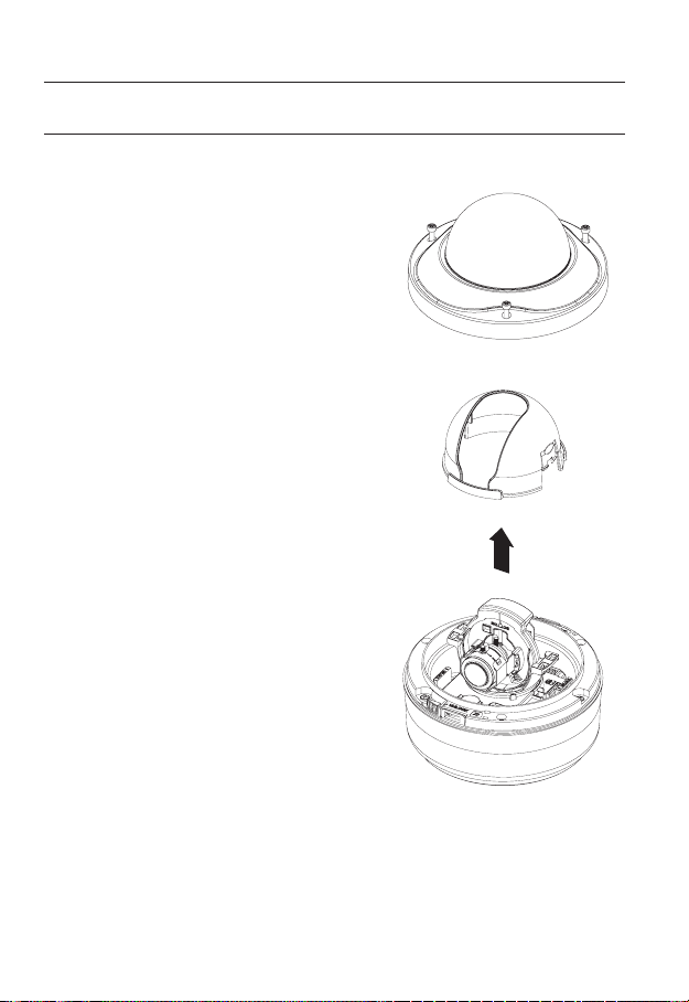
DISASSEMBLING
To connect the alarm in/out, the dome cover and lens cover are to be separated.
1.
Using the L-wrench provided, loosen 3
screws by turning them counterclockwise
and separate the dome cover.
2.
Lift up the inner cover while gently pressing
its both ends to separate it from the unit.
14_ installation & connection
Page 15
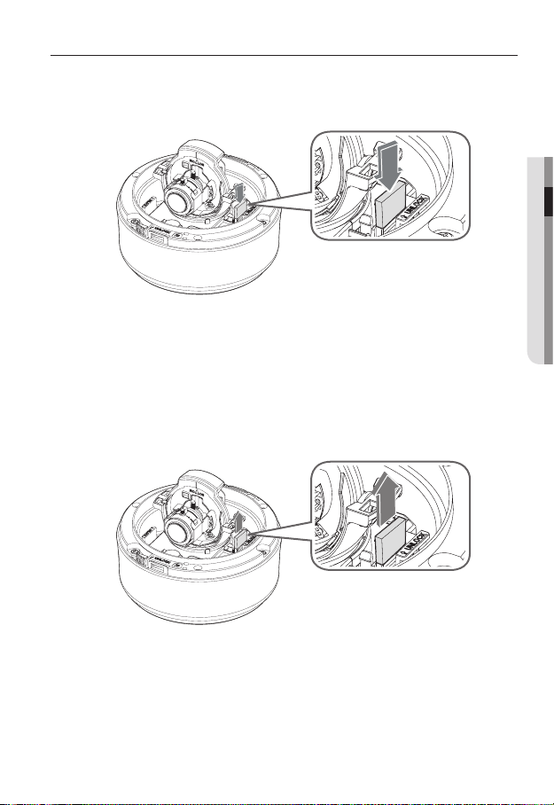
INSERTING/REMOVING AN SD MEMORY CARD
Inserting an SD Memory Card
Push the SD memory card in the direction of the arrow shown in the diagram.
Do not insert the SD memory card while it’s upside down by force. Otherwise, it may damage the
J
SD memory card.
Removing an SD Memory Card
Gently press down on the exposed end of the memory card as shown in the diagram to
eject the memory card from the slot.
● INSTALLATION & CONNECTION
Pressing too hard on the SD memory card can cause the card to shoot out uncontrollably from the
J
slot when released.
Before ejecting the SD memory card, release the checkbox <SD Card Record> in <Alarm
image> and press [Apply] button. (page 67)
English _15
Page 16

installation & connection
MEMORY CARD INFORMATION (NOT INCLUDED)
What is a memory card?
The memory card is an external data storage device that has been developed to offer an
entirely new way to record and share video, audio, and text data using digital devices.
Selecting a memory card that’s suitable for you
Your camera supports SDHC memory cards.
You may, however, experience compatibility issues depending on the model and make of
the memory card.
Your camera supports SD memory cards.
Note that supported memory card capacity is up to 2GB.
For your camera, we recommend you use a memory card from the following manufacturers:
SDHC/SD Memory Card: Panasonic, Sandisk, Toshiba
Your camera supports 128MB to 16GB (SD Card : 2GB) of memory card capacity.
Playback performance can be affected depending on the speed of memory card, so use
the high-speed memory card.
To ensure proper recording of video data, we recommend you use a memory card that
supports at least read/write speed 10Mbps and Class 6.
Memory Card Use
SD and SDHC memory cards feature a switch that disables writing data on to the media.
Having this switch to the Lock position will prevent accidental deletion of data stored in the
memory card but at the same time will also prevent you from writing data on to the media.
Memory Card Components
❖
Contacts
Lock Switch
SDHC
16_ installation & connection
Page 17
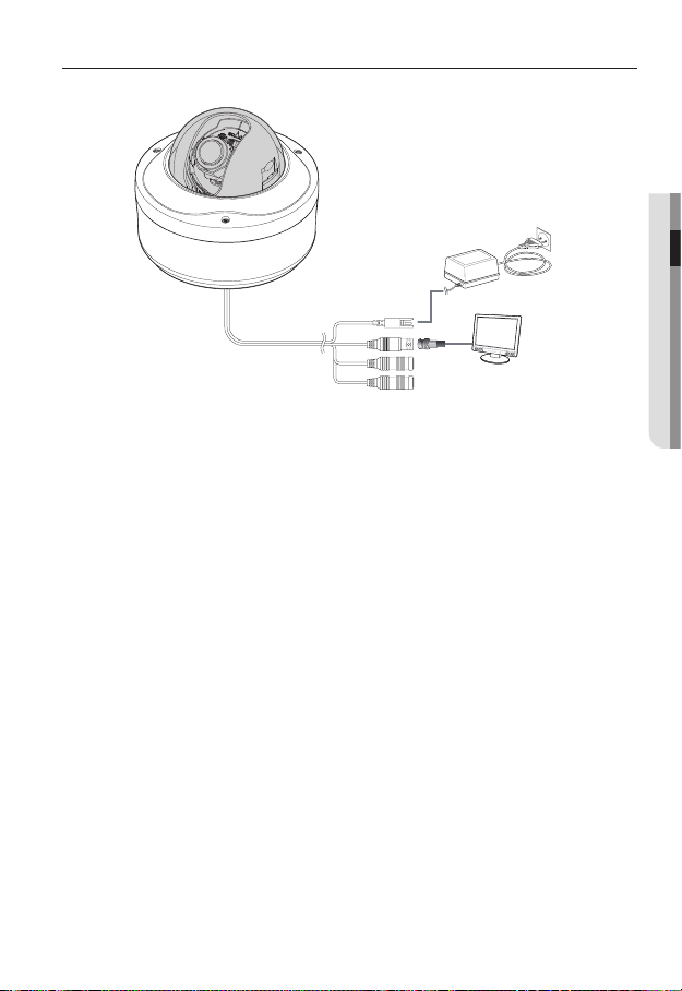
CONNECTING WITH OTHER DEVICE
Power Supply
Connect the power adaptor and camera’s power in jack.
Be careful not to reverse the polarity when you connect the power cable.
J
You can also use a router featuring PoE (Power over Ethernet) to supply power to the camera.
Connecting to the monitor
Connect the camera’s Video Out jack and the monitor’s video in jack.
● INSTALLATION & CONNECTION
Power
Monitor
English _17
Page 18
installation & connection
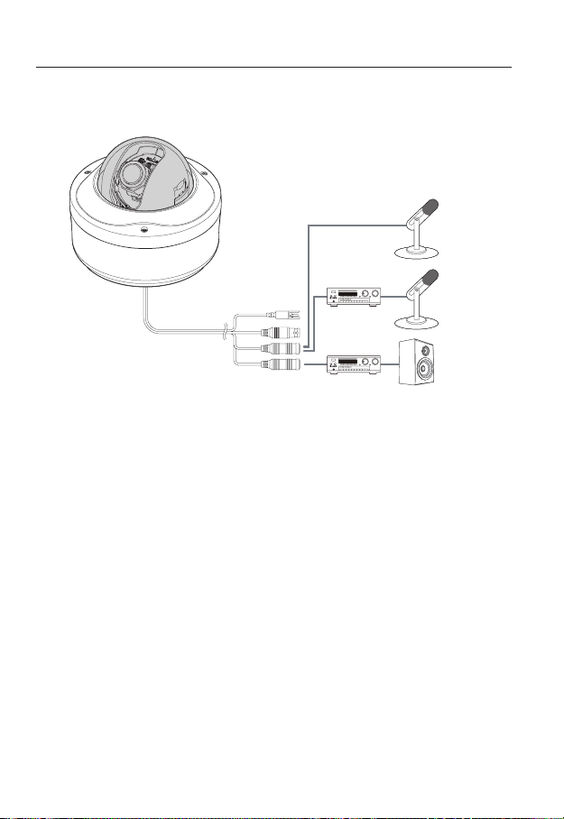
Connecting to Audio Input/Output
LINE-OUT
Microphone
Microphone
LINE-IN
Connect the AUDIO IN port of the camera with the microphone directly or LINE OUT
1.
port of the amplifi er that the microphone is connected to.
y
Direct Mic Connection : Set Audio Input Gain high (10). (Refer to page 56)
y
Line Out Connection : Set Audio Input Gain low (1). (Refer to page 56)
Connect the AUDIO OUT port of the camera with the LINE IN port of the speaker.
2.
18_ installation & connection
Speaker
Page 19
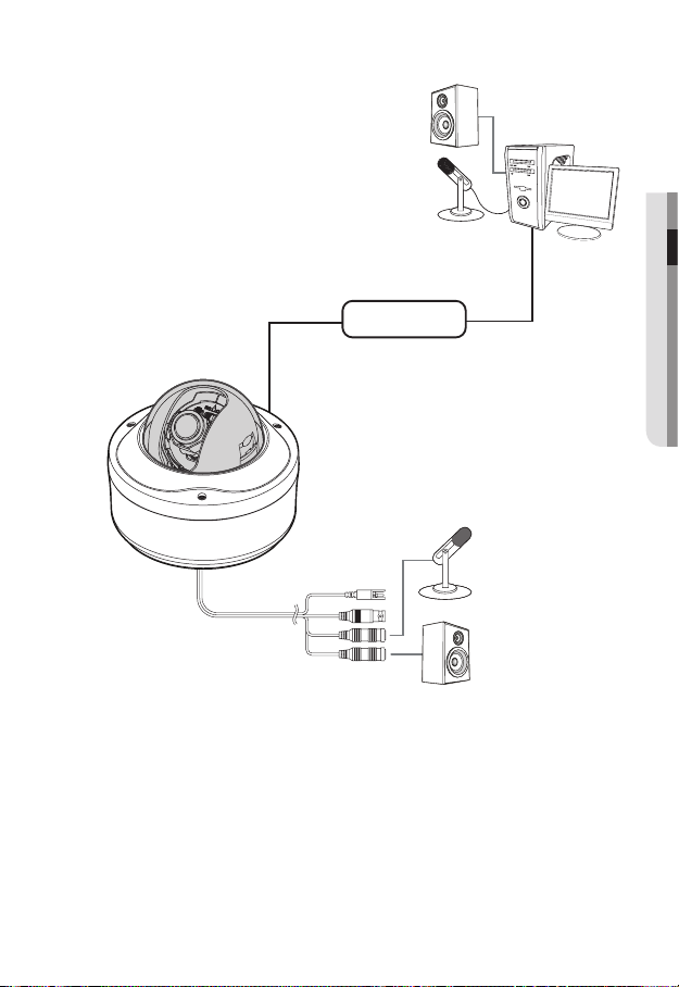
Audio I/O Block Diagram
● INSTALLATION & CONNECTION
PC
Network
Microphone
Speaker
y
Audio Codec
G.711 PCM. µ-law 64kbps 8kHz sampling
y
Full duplex Audio
y
Audio in
Used for mono signal line input (Max.2.4 Vpp)
y
Audio out
Used for mono signal line output (Max.2.4 Vpp)
y
Line out impedance
600
English _19
Page 20
installation & connection
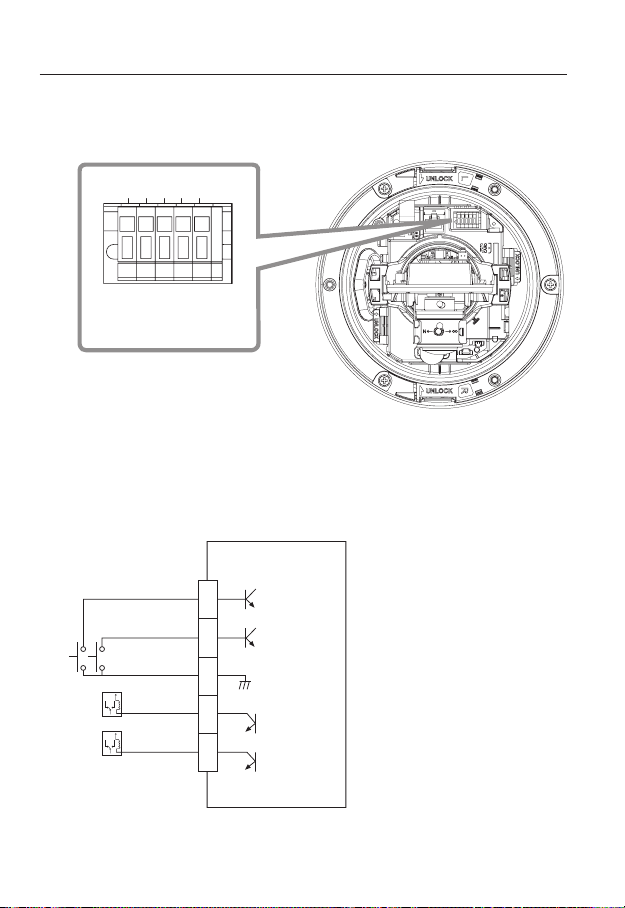
Connecting to the I/O port box
Connect the Alarm I/O cable to the corresponding port of the inner port box.
5 4 3 2 1
1,2 : ALARM IN 1,2
3 : GND
4,5 : ALARM OUT 1,2
y
ALARM IN 1, 2 : Used to connect the alarm input signal.
y
GND : Used for earth-grounding.
y
ALARM OUT 1, 2 : Used to connect the alarm output signal.
Alarm I/O Wiring Diagram
External Relay
External Relay
ALARM IN 1
ALARM IN 2
ALARM OUT 1
ALARM OUT 2
GND
1
2
3
4
5
20_ installation & connection
Page 21
INSTALLATION
Precautions before installation
Ensure you read out the following instructions before installing the camera:
y
Select an installation site (ceiling or wall) that can endure at least 5 times of the
camera weight.
y
Stuck-in or peeled-off cables can cause damage to the product or a fi re.
y
For safety purposes, keep anyone else away from the installation site.
And put aside personal belongings from the site, just in case.
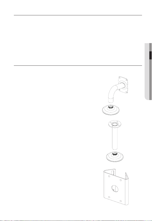
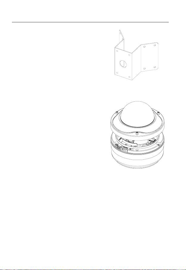
OPTIONAL ACCESSORIES FOR INSTALLATION
For your easier installation, you can purchase appropriate optional accessories available.
1.
WALL MOUNT ADAPTOR(SCX-300WM)/HANGING
MOUNT(SCX-300HM)
This adaptor is used when installing the dome camera
onto a wall.
2.
CEILING MOUNT ADAPTOR(SCX-300CM)/
ING MOUNT(SCX-300HM)
This adaptor is used when installing the dome
camera on a concrete ceiling.
HANG-
● INSTALLATION & CONNECTION
3.
POLE MOUNT ADAPTOR(SCX-300PM)
This is an adaptor for WALL MOUNT ADAPTOR
(SCX-300WM) installation on a pole whose diameter is bigger than 80mm.
English _21
Page 22
installation & connection
CORNER MOUNT ADAPTOR (SCX-300KM)
4.
This is an adaptor for WALL MOUNT ADAPTOR
(SCX-300WM) installation on the corner of wall joint.
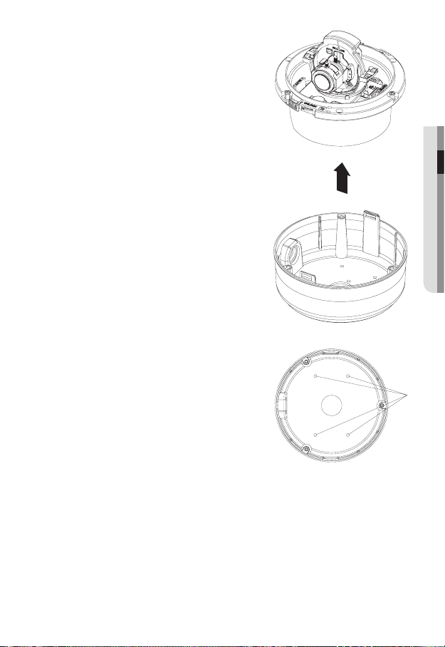
Installing on the ceiling directly
1.
Using the L-wrench provided, loosen 3
screws by turning them counterclockwise
and separate the dome cover.
22_ installation & connection
Page 23
Loosen 3 screws by turning them
2.
counterclockwise, press both left and right
lock releases inwards (in arrow direction) to
unlock the stopper, and then separate the
camera from the case.
Drill holes (diameter 5mm, more than 35mm
3.
deep) on the ceiling by matching to the holes
on the case bed, and insert plastic anchors
(HUD 5) fully into the holes. Fix the case bed
on the ceiling by using Tapping Screws (TH
M4xL30). (4 places)
● INSTALLATION & CONNECTION
Connect power and video cables and arrange cable running not to damage or
4.
squeeze them, and assemble the camera unit in the reverse way.
Adjust the lens aiming to your desired direction.
5.
Assemble the Dome Cover.
6.
For waterproof purpose, fix and secure the bolt using L-wrench provided.
English _23
Page 24
installation & connection
Flushed installation on the ceiling
Using the provided template, drill a hole for the camera unit and fi xing holes (diameter
1.
5mm, more than 35mm deep) on the ceiling. Insert the plastic anchors (HUR-5) fully
into the fi xing holes.
Separate the dome cover and case.
2.
For separating dome cover and case, refer to the steps 1 and 2 of “Installing on
the ceiling directly”.
Connect power and video cables and arrange cable running not to damage or
3.
squeeze them.
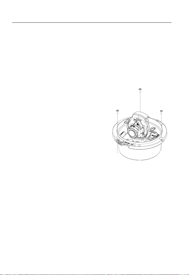
Remove the case assembly screws from the
4.
camera module.
Insert the camera module into the camera
5.
hole, and install it by fastening the Tapping
Screws (TH, M4xL30) by matching the fi xing
holes (3 places).
Assemble the Dome Cover.
6.
Refer tot the step 6 of “Installing on the
ceiling directly".
24_ installation & connection
Page 25
Installing on adaptors (sold separately, SCX-300WM, 300CM,
300KM, 300PM)
Separate the dome cover and case.
1.
For separating dome cover and case, refer
to the steps 1 and 2 of “Installing on the
ceiling directly”.
Assemble and secure the case and adaptor
2.
(sold separately) using 4 fi xing screws (BH,
M4xL8, provided).
Connect power and video cables and
3.
arrange cable running not to damage or
squeeze them, and assemble the camera
unit in the reverse way.
Assemble the Dome Cover.
4.
Refer tot the step 6 of “Installing on the
ceiling directly".
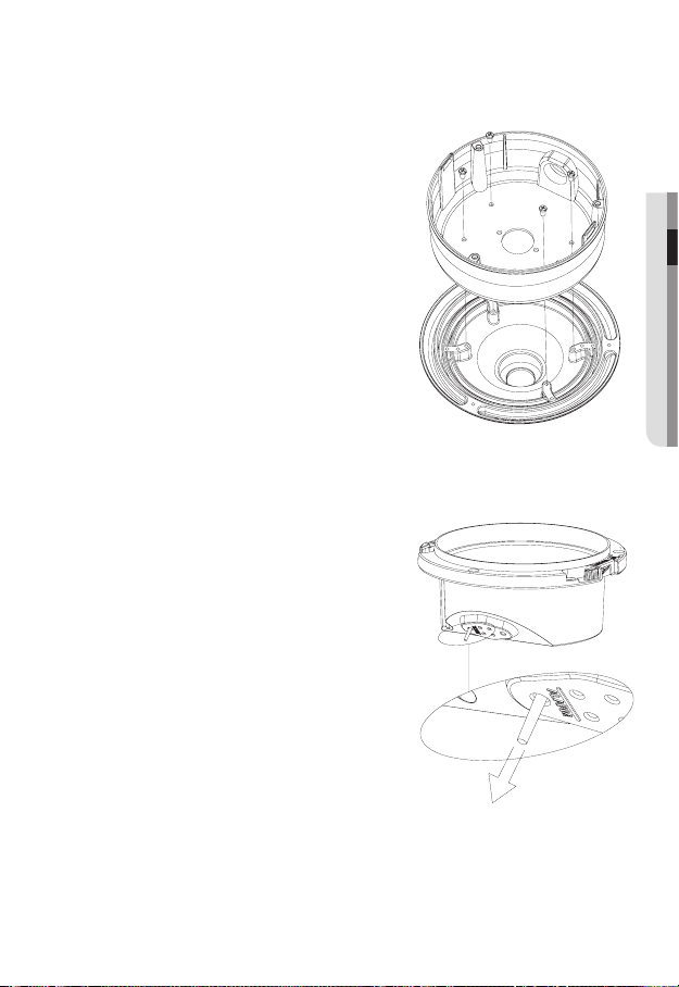
Connecting additional alarm cables
Separate the dome cover and case to
1.
connect alarm cable.
For separating dome cover and case, refer
to the steps 1 and 2 of “Installing on the
ceiling directly”.
Tear off the long rubber plug as illustrated in
2.
the fi gure.
Through the hole opened in step 2 by tearing
3.
the plug off, insert the alarm cable and
connect it to the alarm terminal of the PCB.
Assemble the camera module and the case.
4.
Refer tot the step 4 of “Installing on the ceiling
directly".
Adjust the lens aiming to your desired
5.
direction and assemble the dome cover.
● INSTALLATION & CONNECTION
English _25
Page 26

installation & connection
Adjusting the monitoring direction for the camera
Panning
Tilting
Lens rotation
You can adjust the camera direction only when the camera is fixed on the ceiling.
Then, turning the camera to the left or right is referred to as "Panning", while tilting the
angle is "Tilting". For panning, the panning limit is 220° for the clockwise, and 120° for the
counterclockwise, a total of 340° enabled; further rotation is stopped by the stopper.
26_ installation & connection
Page 27
camera setup
You can configure the camera settings using the Web Viewer.
For accessing the Web Viewer, refer to "Network Connection and Setup". (page 36)
M
HOW TO USE THE MENU KEY
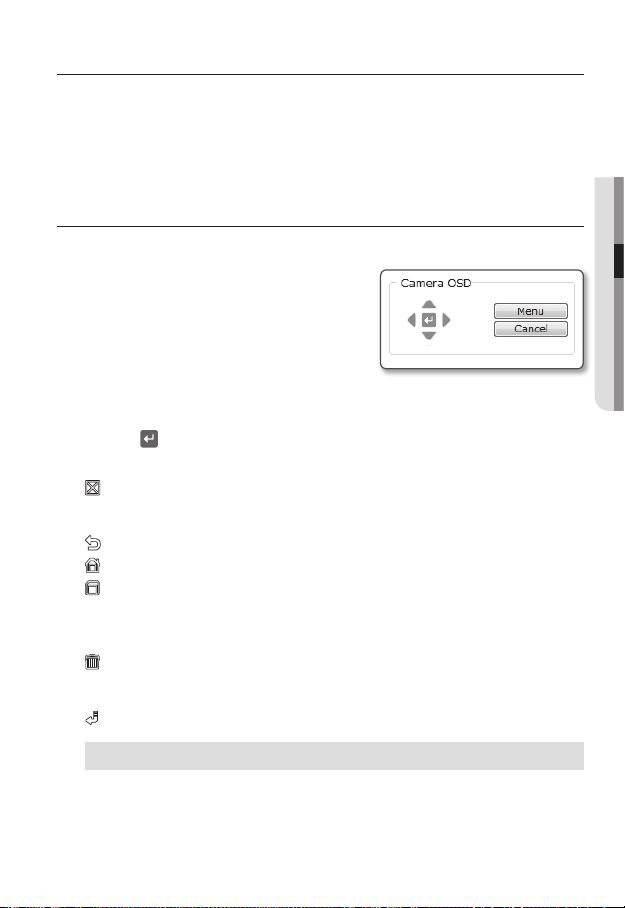
Follow the steps below if you run the Web Viewer for setting the menus.
1.
Launch the Web Viewer.
2.
From the [Camera OSD] menu in the left
pane, click [Menu].
The <MAIN MENU> screen appears.
3.
Click the Up/Down (
desired item.
Click
the four direction (
4.
To change the value of a selected item, click the Left/Right (
5.
Click [
6.
].
Your changes will be applied.
: Exits the menu setup screen.
Before exiting the setup screen, select [SAVE] to save your settings, or [QUIT] to
cancel them.
: Saves your settings and returns to the previous screen.
: Returns to the main menu.
: Use this icon if you want to save your settings after you specified the mask area and
privacy area, etc.
Once you saved your settings, the changes remain intact even if you select [QUIT] on
exit.
: Use this icon if you want to delete a mask, or privacy area, etc.
Once you deleted your settings, the deletions remain valid even if you select [QUIT] on
exit.
: This arrow appears next to a menu that contains sub items.
) buttons to move to a
▲▼
) buttons to navigate through the menu items.
▲▼◄ ►
◄ ►
) buttons.
● CAMERA SETUP
For the items with the "*" mark on the right, You can get help from "Terminology". (page 74)
If intelligent video analysis is enabled, camera’s OSD menu operation can be set as an event.
J
English _27
Page 28
camera setup
**
MAIN M ENU
**
CAMERA SET
PRIVACY ZONE
OTHER S ET
SYSTEM INFO
LANGUAG E
*
STANDARD
ITS
BACKLIG HT
DAY/NIGHT
GAMING
CUSTOM
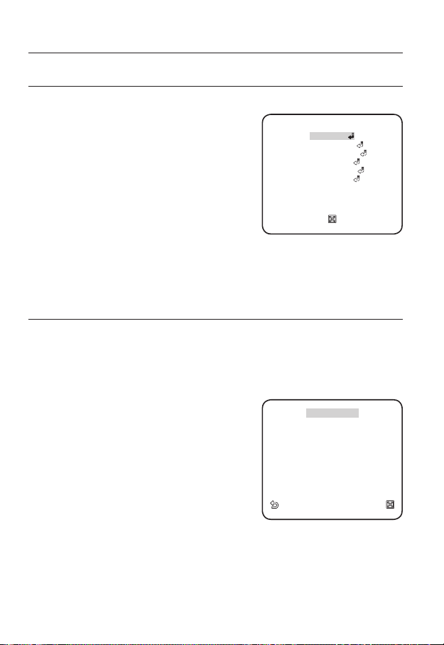
MAIN MENU
You can configure the camera settings to your preference.
y
PROFILE
You can select a mode that is appropriate to the
camera installation environment.
y
CAMERA SET
Confi gure the camera functions and settings.
y
PRIVACY ZONE
You can confi gure the privacy settings.
y
OTHER SET
You can confi gure more settings including
FACTORY DEFAULTS.
y
SYSTEM INFO
Shows the camera version and type.
y
LANGUAGE
Select a preferred one from the supported languages.
PROFILE
You can select one from the pre-determined modes as appropriate to your specific camera installation
environment.
Your selection on each item in PROFILE will affect all other settings of the camera. For the
setting, refer to "PROFILE". (page 73)
For selecting and saving each menu item, refer to "How to use the menu key". (page 27)
y
STANDARD
Automatically optimizes the camera settings to
the normal environment.
y
ITS
This setting enables you to analyze the traffi c
situation and take the traffi c information at a glance.
y
BACKLIGHT
This setting enables you to view a sharp background
and object even in a severe backlight scene.
y
DAY/NIGHT
Automatically optimizes the camera settings to the day and night scene.
y
GAMING
This automatically confi gures the settings so that you can work in a stable illumination
condition as indoors.
y
CUSTOM
Your change to any of the PROFILE settings will switch the display to CUSTOM.
28_ camera setup
**
MAIN MENU
PROFILE
CAMERA SET
PRIVACY ZONE
OTHER SET
SYSTEM INFO
LANGUAGE
◄
PROFILE
*
STANDARD
ITS
BACKLIGHT
DAY/NIGHT
GAMING
CUSTOM
**
►
Page 29
CAMERA SETUP
CAMERA ID
BCD EFG HIJKLMNO PQR STU VWXYZO
123 456 789
: ?
_
+
*() /
SP►► ◄◄ SP LOCATION
- - - - - - - - - - - - - - - - - - - - - - - -
- - - - - - - - - - - - - - - - - - - - - - - - -
ALC
BACKLIG HT OFF
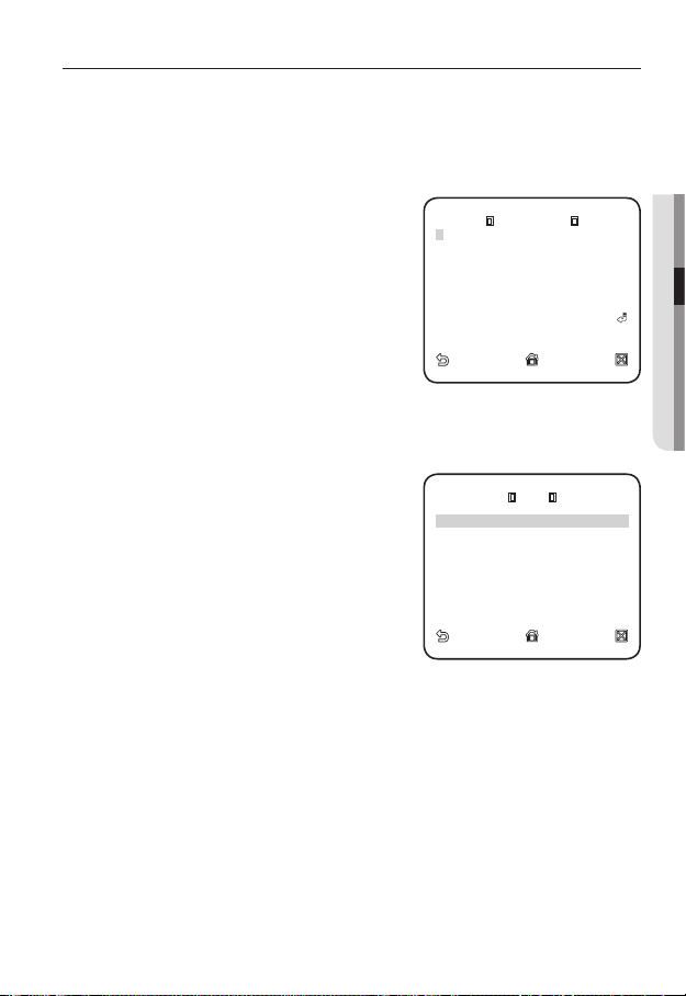
You can configure the general settings of the camera module.
For selecting and saving each menu item, refer to "How to use the menu key". (page 27)
CAMERA ID
Provide the ID and position for a camera that displays on the screen.
1.
Select <CAMERA SET> - <CAMERA ID>.
Use the four direction (
2.
▲▼◄ ►
) buttons to
select a desired character.
In the lower input box of the screen, the
selected character will be entered.
You can enter up to 54 characters including alphabets,
numbers and special characters.
When done, continue to select <LOCATION>
3.
to specify the display position of the camera ID.
IRIS
You can set the iris to control the intensity of radiation incoming to the camera.
Select <CAMERA SET> - <IRIS>.
1.
Use the left/right (
2.
<ALC>.
y
ALC : Controls the luminance automatically.
LEVEL : Select the global brightness level.
BACKLIGHT : Select WDR or BLC.
WDR : Defi ne the composition for weight
factor, the shutter speed in WDR level, and
select outdoor or indoor for white balance
setup.
-
BLC (Backlight compensation) : Confi gure the backlight compensation area by
defi ning the area size and location.
) buttons to select
◄ ►
CAMERA ID
A
BCDEFGHIJKLMNOPQRSTUVWXYZO
123456789
: ?
SP►► ◄◄ SP LOCATION
-
- - - - - - - - - - - - - - - - - - - - - - - -
- - - - - - - - - - - - - - - - - - - - - - - - -
LEVEL
BACKLIGHT OFF
_
+
ALC
*()/
[ 00]
● CAMERA SETUP
----
----
I
If the iris is set to <ALC>, fi xing the iris is your priority when you adjust AE and the shutter speed.
M
English _29
Page 30
camera setup
CAMERA ID ON
IRIS ALC
MOTION (F.FAST)
--DNR MID
SHUTTER OFF
SENS-UP AUTO X4
FLICKER LESS OFF
XDR MID
DIS OFF
WHITE B AL
DIGITAL ZOOM OFF
DETAIL
[
2
]
AGC COL OR SUP MID
REVERSE OFF
POSI/NE GA +
PIP OFF
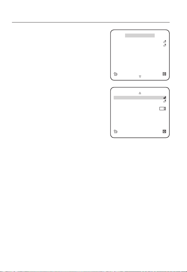
MOTION
You can specify a level of AGC for controlling the
camera motion.
Select F.FAST if you want to monitor a very fast
moving object in a low contrast scene, and S.SLOW
if monitoring a very slow moving, inanimate object in
the same condition.
As long as DAY/NIGHT is set to AUTO, the
◄
CAMERA SET
CAMERA ID ON
IRIS ALC
MOTION (F.FAST)
DNR MID
SHUTTER OFF
SENS-UP AUTO X4
FLICKERLESS OFF
XDR MID
DIS OFF
►
---
<MOTION> menu is not available.
DNR
Reduces the noise on the screen.
This is useful, especially for a noisy screen.
Set it to <USER>, you can specify the level.
SHUTTER
The SHUTTER menu is used to set the fixed fast
electronic shutter or auto fast electronic shutter.
DAY/NIGHT AUTO
WHITE BAL
DIGITAL ZOOM OFF
DETAIL
AGC COLOR SUP MID
REVERSE OFF
POSI/NEGA +
PIP OFF
[
]
2
SENS-UP
If the brightness of the video signal is too low, the Slow Shutter function will be activated.
Slow Shutter can collect the individual max frame rate to adjust the setting.
FLICKERLESS
If set to <ON>, the shutter speed will be fixed to 1/100 second. This will prevent possible
screen distortion due to a mismatch between the vertical sync frequency and the blinking
frequency of the lighting.
If SHUTTER is set to AUTO, FIX, EXT mode / SENSE UP to FIX / AGC to FIX, the <DIS> menu will be
disabled.
XDR
This will correct a brightness difference between different scenes for the optimal visibility.
The higher the value is, the higher the correction level is.
DIS
Automatically compensates for the flicker on the screen.
If set to <ON>, the image will be enlarged with digital zoom as much area as
compensated.
30_ camera setup
Page 31

DAY/NIGHT
AUTO
DAY
NIGHT
BRIGHTN ESS MID
DWELL TI ME 2S
NIGHT
DAY
BRIGHTN ESS MID
DWELL TI ME 5S
MASK AREA 1 2
WHITE BAL
MODE ATW2
RED
[
00
]
----
I
----
BLUE
[
00
]
----
I
----
MASK AREA
<LOCATION>
You can specify a recording mode according to the scene.
1.
Select <CAMERA SET> - <DAY/NIGHT>.
2.
Select a screen transition mode according to the
illumination, and set options as appropriate.
y
DAY : Fixed to DAY mode, regardless of the
scene.
y
NIGHT : Fixed to NIGHT mode, regardless
of the scene.
If BURST is set to <ON>, the burst signal will
BURST OFF
DAY
NIGHT
MASK AREA 1 2
AUTO
NIGHT
BRIGHTNESS MID
DWELL TIME 2S
DAY
BRIGHTNESS MID
DWELL TIME 5S
output.
y
AUTO : According to the luminance, this will
switch DAY to NIGHT mode, or vice versa.
y
DAYNIGHT / NIGHTDAY : If set to
<AUTO>, you can specify the brightness
level triggering the mode switch between
MASK AREA
<SIZE>
<LOCATION>
DAY and NIGHT as well as the interval.
y
MASK AREA : If there exists a bright spot
light source in a night scene, you can specify
the size and position as needed.
Any excessively bright area in a night scene
will be masked.
WHITE BAL
If you need to adjust the screen brightness, use the WHITE BALANCE function.
Select <CAMERA SET> - <WHITE BAL>.
1.
Select a mode where you set the balance.
2.
y
DAY : You can set the RED, and BLUE value
in DAY mode.
y
NIGHT : You can adjust the <WHITE BAL>
according to the ambient luminance.
WHITE BAL
DAY/NIGHT DAY
MODE ATW2
[
RED
[
BLUE
]
----
00
]
----
00
● CAMERA SETUP
----
I
----
I
English _31
Page 32

camera setup
WHITE BAL
DAY/NIGHT NIGHT
BRIGHTN ESS MID
RED
[
00
]
----
I
----
BLUE
[
00
]
----
I
----
R-GAIN
[
0040
]
B-GAIN
[
0133
]
According to the specifi ed recording mode,
3.
select a WHITE BAL mode with necessary
options.
y
BRIGHTNESS : Specify a brightness level
triggering the switch from DAY to NIGHT
mode.
y
MODE : According to the selected mode,
you can adjust the RED and BLUE color
level.
RED : Adjust the strength of the red color.
BLUE : Adjust the strength of the blue color.
R-GAIN/B-GAIN : Specify the current color temperature manually.
-
You can set the R-GAIN, and B-GAIN value only in AWC mode.
DIGITAL ZOOM
You can set the digital zoom factor and position.
When the zoom factor and position are defined, the digital zoom function will operate.
If you set the digital zoom to a larger factor than the actual enlargement for compensation, the DIS
function will be disabled.
DETAIL
You can adjust the vertical and horizontal sharpness, respectively.
AGC COLOR SUP
This will adjust the color scheme according to the AGC value.
REVERSE
This will reverse the signal left to right, top to bottom, or a combination of the preceding.
POSI/NEGA
This will display the video brightness signal either normally or reversely.
PIP
You can view a main image with a sub image on the same screen.
WHITE BAL
DAY/NIGHT NIGHT
BRIGHTNESS MID
MODE AW C
[
RED
[
BLUE
R-GAIN
B-GAIN
00
00
[
0040
[
0133
]
----
]
---]
]
----
I
----
I
32_ camera setup
Page 33

PRIVACY ZONE
1 2 3 4 5 6
7 8 9 10 11 12
PRIVACY SET
ON
STYLE
MOSAIC1
PRIVACY ZONE SET 1
<POINT>
<POSITI ON>
You can set up to 12 privacy zones that will be hided for privacy of the subject when recording.
For selecting and saving each menu item, refer to "How to use the menu key". (page 27)
ZONE SETUP
Select <MAIN MENU> - <PRIVACY ZONE>.
1.
Use the four direction (
2.
▲▼◄ ►
) buttons to
select a desired number.
The Zone setup screen appears.
Select the <PIXEL LEVEL>.
3.
Specify the pixel unit level for the POSITION setting.
Select <POINT>.
4.
You will see dots on the screen.
Use the four direction (
5.
▲▼◄ ►
) buttons to specify
the position for each of the four dots.
Select <POSITION> and use the four direction
6.
) buttons to specify the position for each
(
▲▼◄ ►
of the four dots.
Save the changes and move to the previous screen and select the <STYLE>.
7.
Select <COLOR> and pick a desired color.
Setting one or more privacy zone and enabling privacy function will disable the PIP function.
M
◄
PRIVACY ZONE
1 2 3 4 5 6
7 8 9 10 11 12
PRIVACY SET
STYLE
PRIVACY ZONE SET 1
PIXEL LEVEL
<POINT>
<POSITION>
[4]
►
MOSAIC1
ON
● CAMERA SETUP
English _33
Page 34

camera setup
FACTORY DEFAULTS
OSD COL OR BW
FACTORY DEFAULTS
OK
OTHERS
You can reset the camera, or select the OSD font color to your preference.
For selecting and saving each menu item, refer to "How to use the menu key". (page 27)
FACTORY DEFAULT
Select <MAIN MENU> - <OTHER SET>
1.
- <FACTORY DEFAULTS>.
The FACTORY DEFAULTS setup screen
appears.
Select <OK>.
2.
All the settings will be restored to the factory
default.
However, the language setting will not be
restored.
◄
OTHER SET
FACTORY DEFAULTS
OSD COLOR BW
FACTORY DEFAULTS
OK
►
CANCEL
OSD COLOR
You can set the font color of the user interface.
34_ camera setup
Page 35

SYSTEM INFO
TYPE 3
_
IPV
_
P
CAMERA VER. v1.00_090828
*
ENGLISH
FRANÇAI S
DEUTSCH
ESPAÑOL
ITALIANO
You can check the system information.
For selecting and saving each menu item, refer to "How to use the menu key". (page 27)
Select <MAIN MENU> - <SYSTEM INFO>.
1.
The current system information is displayed.
2.
The camera type may different, depend on the video
M
signal.
◄
SYSTEM INFO
TYPE 3
CAMERA VER. v1.00_090828
LANGUAGE
You can select a language to your preference.
For selecting and saving each menu item, refer to "How to use the menu key". (page 27)
Select <MAIN MENU> - <LANGUAGE>.
1.
Select your preferred language using the
2.
up/down (
M
) buttons.
Supported language may different.
◄
LANGUAGE
*
ENGLISH
FRANÇAIS
DEUTSCH
ESPAÑOL
ITALIANO
►
_
_
IPV
P
● CAMERA SETUP
►
English _35
Page 36

network connection and setup
You can set up the network settings according to your network configurations.
CONNECTING THE CAMERA TO AN IP ROUTER WITH THE
XDSL/CABLE MODEM
This is for a small network environment such as homes, SOHO and ordinary shops.
SNC-B5399
INTERNET
xDSL 또는
xDSL or
SNC-B5399
로컬PC
Local PC
IP공유기
IP Router
Cable 모뎀
Cable Modem
DDNS 서버
DDNS Server
(Data Center, KOREA)
Configuring the network settings of the local PC connected to an
IP router
Configuring the network settings of the local PC connected to an IP router, follow the
instructions below.
y
Select : <Network Neighborhood> <Properties> <Local Area Connection>
<Properties> <General> <Internet Protocol (TCP/IP)> <Properties>
<Obtain an IP address automatically> or <Use the following IP address>.
y
Follow the instructions below if you select <Use the following IP address>:
ex1) If the address (LAN IP) of the IP router is 192.168.1.1
IP address: 192.168.1.100
Subnet Mask: 255.255.255.0
Default Gateway: 192.168.1.1
ex2) If the address (LAN IP) of the IP router is 192.168.0.1
IP address: 192.168.0.100
Subnet Mask: 255.255.255.0
Default Gateway: 192.168.0.1
ex3) If the address (LAN IP) of the IP router is 192.168.xxx.1
IP address: 192.168.xxx.100
Subnet Mask: 255.255.255.0
Default Gateway: 192.168.xxx.1
For the address of the IP router, refer to the product’s documentation.
M
36_ network connection and setup
xDSL 또는
xDSL or
Cable 모뎀
Cable Modem
외부 원격 PC
External Remote
PC
Page 37

Checking if the IP router is connected to the xDSL/Cable modem properly
Select <Status> from the Settings menu of the IP Router
y
If it is properly connected, <IP Address>, <Subnet Mask> and <Gateway>
provided by your ISP are displayed. Please remember these values because they
are required so that an external remote computer of the IP router connects to the
camera. However, note that certain ISPs change the settings of <IP Address>,
<Subnet Mask> and <Gateway> on a regular basis
y
If the IP router is not properly connected, press the [Connect] button to try to reconnect or check if the settings of the IP router are correct.
●
NETWORK CONNECTION AND SETUP
CONNECTING THE CAMERA TO AN IP ROUTER WITH
LOCAL AREA NETWORKING
This is for a large network environment such as corporate office, building, public office and factory.
SNC-B5399
Switch
HUB
IP 공유
기
SNC-B5399
로컬PC
Local PC
IP Router External
Local PC
Configuring the network settings of the local PC connected to an
IP router
Configuring the network settings of the local PC connected to an IP router, follow the
instructions below.
y
Select : <Network Neighborhood> <Properties> <Local Area Connection>
<Properties> <General> <Internet Protocol (TCP/IP)> <Properties>
<Obtain an IP address automatically> or <Use the following IP address>.
y
Follow the instructions below if you select <Use the following IP address>:
ex1) If the address (LAN IP) of the IP router is 192.168.1.1
IP address: 192.168.1.100
Subnet Mask: 255.255.255.0
Default Gateway: 192.168.1.1
ex2) If the address (LAN IP) of the IP router is 192.168.0.1
IP address: 192.168.0.100
Subnet Mask: 255.255.255.0
Default Gateway: 192.168.0.1
Firewall
방화벽
(Data Center, KOREA)
(Data Center, KOREA)
INTERNET
DDNS 서버
DDNS Server
외부 원격 PC
Remote PC
English _37
Page 38

network connection and setup
ex3) If the address (LAN IP) of the IP router is 192.168.xxx.1
IP address: 192.168.xxx.100
Subnet Mask: 255.255.255.0
Default Gateway: 192.168.xxx.1
For the address of the IP router, refer to the product’s documentation.
M
CONNECTING THE CAMERA DIRECTLY TO A DHCPBASED XDSL/CABLE MODEM
INTERNET
DDNS Server
DDNS 서버
(Data Center, KOREA)
(Data Center, KOREA)
외부 원격 PC
External
Remote PC
SNC-B5399
xDSL 또는
xDSL or
Cable 모뎀
Cable Modem
Setting the IP Router
This is enabled for a modem using DHCP.
1.
Set the Static or Dynamic IP address. (pages 41~45)
2.
Launch an Internet browser on the local PC connected to the IP Router.
3.
Enter the IP Router’s address in the address bar of the browser.
ex) http://192.168.1.1, http://192.168.0.1
or http://192.168.xxx.1
For the DDNS URL address, refer to "To check the DDNS address". (page 48)
4.
When the IP Router is connected, the login window appears and prompts you to
enter the password.
For the login IP and the password, refer to the IP router’s documentation.
5.
When done, you will see the setup window of the IP router. In the setup menu,
select “Automatic Confi guration-DHCP” for Internet Connection Type.
For the menu location of Internet Connection Type or DHCP selection, refer to the IP router’s
documentation.
6.
When done, click the [Save] or [Apply] button to save the settings.
38_ network connection and setup
Page 39

CONNECTING THE CAMERA DIRECTLY TO LOCAL AREA
NETWORKING
Connecting to the camera from a local PC in the LAN
Launch an Internet browser on the local PC.
1.
Enter the IP address of the camera in the address bar of the browser.
2.
SNC-B5399
●
NETWORK CONNECTION AND SETUP
Switch
HUB
SNC-B5399
로컬 PC
Local PC
A remote PC in an external Internet out of the LAN network may not be able to connect to the
M
camera installed in the intranet if the port-forwarding is not properly set or a fi rewall is set.
Firewall
방화벽
INTERNET
DDNS Server
DDNS 서버
(Data Center, KOREA
(Data Center, KOREA)
In this case, to resolve the problem, contact your network administrator.
External
외부 원격 PC
Remote PC
)
English _39
Page 40

network connection and setup
IP ADDRESS SETUP
Buttons used in IP Installer
Item Description
Device Name
Mode
MAC(Ethernet)
Address
IP Address
Protocol
UPnP Status This function is not currently implemented.
Model name of the connected camera.
Click the column to sort the list by model name.
However, search will be stopped if clicked during the search.
Displays either <Static> or <Dynamic> for the current network connection
status.
Ethernet address for the connected camera.
Click the column to sort the list by Ethernet address.
However, search will be stopped if clicked during the search.
IP address.
Click the column to sort the list by IP address.
However, search will be stopped if clicked during the search.
The factory default is "192.168.1.200".
Network setting for the camera.
The factory default is "IPv4".
Cameras with the IPv6 setting will be displayed "IPv6".
40_ network connection and setup
Page 41

URL
IPv4 Scans for cameras with the IPv4 setting.
IPv6 Scans for cameras with the IPv6 setting.
Search
Auto Set <IP Installer> will automatically configure the network settings for you.
Manual Set You should configure the network settings manually.
Exit Exits the IP Installer program.
DDNS URL address enabling access from the external Internet.
However, this will be replaced with the <IP Address> of the camera if
DDNS registration has failed.
Scans for cameras that are currently connected to the network.
However, this button will be grayed out if neither IPv4 nor IPv6 is checked.
STATIC IP SETUP
Manual Network Setup
Run <IP Installer.exe> to display the camera search list.
At the initial startup, both [Auto Set] and [Manual Set] will be grayed out.
For cameras found with the IPv6 setting, these buttons will be grayed out as the cameras do not
M
support this function.
Select a camera in the search list.
1.
Find the MAC (Ethernet) address labeled
on the rear of the camera.
Both the [Auto Set] and [Manual Set]
buttons will be activated.
2.
Click [Manual Set].
The MANUAL SET dialog appears.
The default values of <IP Address>,
<Subnet Mask>, <Gateway>, and <HTTP Port> of the camera will be displayed.
The default <PASSWORD> is 4321.
3.
In the <ADDRESS> pane, provide the
necessary information.
MAC (Ethernet) Address : The MAC
(Ethernet) address of the applicable
camera will be set automatically so you
don't need to input it manually.
●
NETWORK CONNECTION AND SETUP
English _41
Page 42

network connection and setup
If using an IP router :
y
IP Address : Enter an address falling in
the IP range provided by the IP router.
ex) 192.168.1.2~254,
192.168.0.2~254,
192.168.XXX.2~254
y
Subnet Mask : The <Subnet Mask> of
the IP router will be the <Subnet Mask>
of the camera.
y
Gateway : The <Local IP Address> of
the IP router will be the <Gateway> of the camera.
If not using an IP router :
For setting <IP Address>, <Subnet Mask>, and <Gateway>, contact your network
administrator.
The values of Device, TCP, UDP, Upload, and Multicast ports can not be changed manually, and
M
will be adjusted according to the HTTP port value.
4.
In the <PORT> pane, provide
necessary information.
y
HTTP Port : Used to access the
camera using the Internet browser,
defaulted to 80. Use the spin button
to change the HTTP Port value. The
start value of the port is 80, and
increases or decreases by 6 like
10000, 10006, 10012.
y
Device Port : Used to control the video signal transfer, defaulted to 60001(TCP).
y
TCP Port : Video signal transfer port using TCP protocols, defaulted to
60002(TCP).
y
UDP Port : Video signal transfer port using the UDP Unicast method, defaulted to
60003(UDP).
y
Upload Port : Used to upgrade the software fi rmware, defaulted to 60004(TCP).
y
Multicast Port : Video signal transfer port using the UDP Multicast method,
defaulted to 60005(UDP).
Enter the password.
5.
This is the login password for the "root" user who accesses the camera.
The default password is "4321".
42_ network connection and setup
Page 43

6.
Click [OK].
Manual network setup will be completed.
7.
When the manual setup including <IP> is completed, the camera will restart.
If the IP router has more than one camera connected
Configure the IP related settings and the Port related settings distinctly with each other.
Category Camera #1 Camera #2
IP related settings
Port related settings
If the <HTTP Port> is set other than 80, you must provide the <PORT> number in the address
M
bar of the Internet browser before you can access the camera.
ex) http://IP address : HTTP Port
IP Address
Subnet Mask
Gateway
HTTP Port
Device Port
TCP Port
UDP Port
Upload Port
Multicast Port
http://192.168.1.201:10000
192.168.1.200
255.255.255.0
192.168.1.1
80
60001
60002
60003
60004
60005
192.168.1.201
255.255.255.0
192.168.1.1
10000
10001
10002
10003
10004
10005
Auto Network Setup
Run <IP Installer.exe> to display the camera search list.
At the initial startup, both [Auto Set] and [Manual Set] will be grayed out.
For cameras found with the IPv6 setting, these buttons will be grayed out as the cameras do not
M
support this function.
●
NETWORK CONNECTION AND SETUP
Select a camera in the search list.
1.
Find the MAC (Ethernet) address labeled
on the rear of the camera.
Both the [Auto Set] and [Manual Set]
buttons will be activated.
2.
Click [Auto Set].
The AUTO SET dialog appears.
The <IP Address>, <Subnet Mask>,
and <Gateway> will be set automatically.
English _43
Page 44

network connection and setup
Enter the password.
3.
This is the login password for the "root"
user who accesses the camera.
The default password is "4321".
Click [OK].
4.
Auto network setup will be completed.
The camera will automatically complete
5.
the network setting and restart.
DYNAMIC IP SETUP
Dynamic IP Environment Setup
y
Example of the dynamic IP environment
If an IP router, with cameras connected, is assigned an IP address by the DHCP
server
If connecting the camera directly to the xDSL or cable modem using the DHCP
protocols
-
If IPs are assigned by the internal DHCP server via the LAN
Checking the dynamic IP
From a local PC, run <IP Installer>
1.
to display a list of cameras that are
assigned <Dynamic IP>.
Select a camera in the list, and click
2.
[Manual Set] to check the <Dynamic
IP> of the camera.
If you uncheck <DHCP>, you can
change <IP> or <PORT> to <STATIC>.
44_ network connection and setup
Page 45

PORT RANGE FORWARD (PORT MAPPING) SETUP
If you have installed an IP router with a camera connected, you must set the port range
forwarding on the IP router so that a remote PC can access the camera in it.
Manual Port Range Forwarding
1.
From the Setup menu of the IP router,
select <Applications & Gaming> <Port Range Forward>.
For setting the port range forward for
a third-party IP router, refer to the user
guide of that IP router.
2.
Select <TCP> and <UDP Port> for
each connected camera to the IP
router.
Each port number for the IP router
should match that specifi ed in <Basic>
- <IP> from the camera's Setup menu.
3.
When done, click [Save Settings].
Your settings will be saved.
●
NETWORK CONNECTION AND SETUP
English _45
Page 46

network connection and setup
CONNECTING TO THE CAMERA FROM A SHARED LOCAL
PC
Launch <IP Installer>.
1.
It will scan for connected cameras and
display a list of them.
Double-click a camera to access.
2.
The Internet browser starts and
connects to the camera.
You can also access the camera in such way you type the IP address of the found camera in the
M
address bar of the Internet browser.
CONNECTING TO THE CAMERA FROM A REMOTE PC VIA
THE INTERNET
As a remote PC can not directly access <IP Installer>, you should access the camera in the IP
router network using DDNS URL of the camera.
Before you can access a camera in the IP router network, you should have set the
1.
port range forward for the IP router.
From the remote PC, launch the Internet browser and type the DDNS URL address
2.
of the camera, or the IP address of the IP router in the address bar.
ex) http://mfffe42.websamsung.net
For the DDNS URL address, refer to "To check the DDNS address". (page 48)
46_ network connection and setup
Page 47

web viewer
CONNECTING TO THE CAMERA
Normally, you would
Launch the Internet browser.
1.
Type the IP address of the camera in
2.
the address bar.
IP address (IPv4) : 192.168.1.200
ex) •
http://192.168.1.200
- the Login dialog should appear.
IP address
•
ffff:0000:0000:ffff:1111
:0000:ffff:1111]
If the HTTP port is other than 80
Launch the Internet browser.
1.
Type the IP address and HTTP port number of the camera in the address bar.
2.
ex) IP address : 192.168.1.200:Port number(10000) http://192.168.1.200:10000
- the Login dialog should appear.
Using URL
Launch the Internet browser.
1.
Type the DDNS URL of the camera in the address bar.
2.
ex) URL address : http://mfffe42.websamsung.net
- the Login dialog should appear.
Connecting via URL (If the HTTP port is other than 80)
Launch the Internet browser.
1.
Type the DDNS URL and HTTP port number of the camera in the address bar.
2.
ex) URL address : http://mfffe42.websamsung.net:Port number(10000)
- the Login dialog should appear.
(IPv6) :
2001:230:abcd:
http://[2001:230:abcd:ffff:0000
http://mfffe42.websamsung.net:10000
● WEB VIEWER
English _47
Page 48

web viewer
To check the DDNS address
The DDNS address consists of: <one of the lower-case letters: c, m, p> + <the last 6 digits
of the MAC (Ethernet) address> + <websamsung.net>
The small letter will be <c> if the first 6 digits of the MAC (Ethernet) address is <00:00:f0>,
or <m> if they are <00:16:6c>, or <p> for <00:68:36>.
ex) - If the MAC (Ethernet) address is 00:00:f0:ff:fe:42: c + fffe42 + websamsung.net =
cfffe42.websamsung.net
If the MAC (Ethernet) address is 00:16:6c:ff:fe:42: m + fffe42 +websamsung.net =
-
mfffe42.websamsung.net
-
If the MAC (Ethernet) address is 00:68:36:ff:fe:42: p + fffe42 +websamsung.net =
pfffe42.websamsung.net
The above mentioned addresses are simply examples; do not use any of these for connecting
J
purposes.
LOGIN
The default user ID is "root", and the default password is "4321".
Enter "root" in the <User Name> input
1.
box.
Enter "4321" in the <Password> input
2.
box.
If the password is changed, enter the
changed password instead.
Click [OK].
3.
If you have logged in successfully, you
will the Live Viewer screen.
For security purposes, ensure that you change the password in <Basic> - <User>.
M
The administrator ID, "root", is fi xed and can not be changed.
If you check the "Save this password in your password list" option when your input is done, you
will be logged in automatically without being prompted to enter the login information from next time on.
For this, your computer has installed DirectX 8.1 or later.
J
You can get a free download of the latest DirectX from http://www.microsoft.com/download.
If you are using Internet Explorer 7.0 or 8.0 as the default web browser, you can view the best
quality image with a screen ratio of 100%. Reducing the ratio may cut the image on the borders.
48_ web viewer
Page 49

INSTALLING ACTIVEX
If connecting to a camera for the first time, you will see the installation message. Then, install the
required ActiveX to access the camera and control the video from it in real time.
For Windows XP Service Pack 2 users
Click the installation message that pops
1.
up when you fi rst access the camera.
Click <Install ActiveX Control...>.
2.
The security warning popup appears,
3.
click [Install].
When the required ActiveX is installed
4.
properly after your access to the camera,
the Live screen should appear.
For normal installation, set the Block
J
Popup setting as follows:
Internet Explorer ➝ Tools ➝ Block
Popup ➝ Always allow popups from
the current site(A)
● WEB VIEWER
English _49
Page 50

web viewer
USING THE LIVE SCREEN
Item Description
SD Search Moves to the screen for searching event images from the SD card.
Setup Move to the Setup screen.
About You can check the firmware version, serial number and manufacturer information.
Reset Alarm
Capture Saves the snapshot as an image file in the .jpeg or .bmp format.
Print Prints out the current image.
Record Records the current video in avi movie file format.
Full Screen Displays the Live screen in full screen.
Video format
Resets the Alarm icon. (Alarm and Intelligent Video Analysis icons will disappear.)
You can set the video format(MJPEG, H.264/MPEG4) for video files.
Note that the menu configuration may differ from your setup of <H.264 & MPEG4
video select> in Video Setup menu.
50_ web viewer
Page 51

Alarm output
On : Activates the specified Alarm Out port.
Off : Deactivates the specified Alarm Out port.
Pulse : Activates the Alarm Out port as much time as specified before deactivating it.
Camera OSD
Audio
Viewer Screen Displays the Live video on the screen.
Used to retrieve and customize the Camera Setup menu.
For selecting and saving each menu item, refer to "How to use the menu key". (page 27)
Check the Listen or Speak check box for Audio.
BACKUP
You can capture, print out, and save the snapshot in the specified path.
To capture the snapshot
Click [ ] on the scene to capture.
1.
The Capture dialog should appear.
Click [OK].
2.
The screenshot will be saved in the
specifi ed path.
y
Default fi le path
Windows XP : C:\Program Files\Samsung\SNC-B5399\SnapShot\Live
-
If you want to change the path, click [Set path (
Windows Vista : C:\users\[UserID]\AppData\LocalLow\Samsung\SNC-B5399\
SnapShot\Live
On the Windows Vista system, the path to save is fi xed.
y
The screenshot fi le will be named automatically in the format of <IP address_Port
number_YYYYMMDD_hhmmss_index>.
ex) 192.168.0.200_60001_20000114_133857_00
)] and specify a path.
● WEB VIEWER
English _51
Page 52

web viewer
To print out the screenshot
Click [ ] on the scene to print out.
1.
The Print setup dialog appears.
Specify the name of the printer
2.
connected, and click [OK].
To record a video
Click [ ] on the scene to record.
1.
You will see the Save AVI dialog;
2.
provide the necessary information.
y
Save path : You can change the
default saving path.
y
File name : You can change the
default fi le name.
y
HDD minimum free size : If the free
space on the HDD is less than the
recorded space, recording will be forcibly ended.
3.
Click [OK].
Recording will start with the display of
<REC> on the viewer screen.
The video file will be saved into the
specified path.
4.
If you want to quit recording, click [
again.
]
52_ web viewer
Page 53

y
Default fi le path
-
Windows XP : C:\Program Files\Samsung\SNC-B5399\VideoClip\Live
If you want to change the path, click [Set path (
-
Windows Vista : C:\users\[UserID]\AppData\LocalLow\Samsung\SNC-B5399\
)] and specify a path.
VideoClip\Live
On the Windows Vista system, the path to save is fi xed.
y
The screenshot fi le will be named automatically in the format of <IP address_Port
number_YYYYMMDD_hhmmss_index>.
ex) 192.168.0.200_60001_20090903_112357_00
y
If you want to play an .avi fi le, you must have installed the corresponding DivX
codec on your system.
You can get a free download of the DivX from http://sourceforge.net/projects/
ffdshow/.
● WEB VIEWER
English _53
Page 54

web viewer
USING THE SD SEARCH VIEWER SCREEN
Click <SD search> tab in the Live screen.
1.
2.
The SD Search Screen appears.
SD Search Viewer Screen layout
Name Function and description
Thumbnail Size The thumbnail images are displayed based on the selected size.
Date You can select the desired date to search for events generated.
Schedule You can select the desired time to search the schedule events.
Alarm input
Intelligent video
analysis
54_ web viewer
You can select the desired time to search the alarm events.
You can search for events of intelligent video analysis by specifying the time period.
Page 55

setup screen
ACCESSING THE SETUP SCREEN
You can configure the default setting, system, overlay, event and network related settings, and
change them as necessary.
In the Live screen, click the <Setup> tab.
1.
2.
The Setup screen appears.
DEFAULT SETUP
To configure the video & audio
settings
You can set the video resolution, quality,
CODEC and audio input/output settings.
1.
Select <Basic> - <Video & Audio>.
The Video & Audio setup screen appears.
y
Brightness : Adjust the screen
brightness from 1 to 100.
y
Contrast : Adjust the contrast from
1 to 100.
y
Resolution : Set the video size of the
MPEG4, H.264, and MPEG fi les.
-
NTSC : 4CIF(704x480),
VGA(640X480), CIF(352X240)
-
PAL : 4CIF(704x576),
VGA(640X480), CIF(352X288)
y
Quality : Adjust the picture quality
from 1 to 10.
y
Frame rate : Select one from 30 fps,
15 fps, 8 fps, 3 fps, and 1 fps.
y
Bitrate control* : Select CBR (Constant
Bit Rate) or VBR (Variable Bit Rate) for
the compression method.
If selecting VBR, you can not set the target
bit rate.
● SETUP SCREEN
English _55
Page 56

setup screen
y
Target bitrate : Transfers video signal at a specifi ed bit rate.
y
Compression : Adjust the compression rate from 5 through 100 by 5.
y
Encode priority : Set the video transfer method to Frame rate or Quality.
y
GOP* size : Select a GOP size between 5 and 15.
y
Deblock : This will soften the edges between macro blocks.
y
De-Interlace : You can reduce the grid noise by using the de-interlacing function.
Only available if MPEG4 resolution is set to 4CIF.
If the WDR is set to <OFF> or the MPEG4 resolution is not 4CIF, you cannot enable the
J
MPEG4 CODEC’s de-interlacing
y
Profile : Select Baseline or Main for the H.264 profiling method.
y
Entropy coding* : Reduces the compression loss due to encoding.
If you set the profi le to Baseline, the entropy coding is available only for CAVLC*; if you set it
J
to MAIN, the entropy coding is available for both CAVLC* and CABAC*.
y
Motion estimation :
y
Input gain : You can set the audio input gain from 0 to 10.
y
Output gain : You can set the audio output gain from 0 to 10.
J
2.
When done, click [Apply].
Your settings will be saved.
Estimates the movement of pixels by determining the motion vector.
If the audio input gain is set to 0, no sound is heard.
56_ setup screen
Page 57

To configure the IP settings
Select <Basic> - <IP>.
1.
The IP setup window appears.
y
IP confi guration : Set the IP and port
settings for the camera.
-
IP type : Select one from <Static
IP>, <Dynamic IP>, and <PPPoE
IP>.
If you select <PPPoE IP>, you can
provide the optional ADSL IP and
password. However, the multicast items
(multicast address, port, TTL) for VNP
and RTP will disappear.
-
MAC address : Displays the
Ethernet MAC address.
This is used for creating a DDNS
address.
-
IP address : Displays the current IP
address.
-
Subnet mask : Displays the
<Subnet mask> for the set IP.
-
Gateway : Displays the <Gateway> for the set IP.
-
DNS server : Displays the DNS(Domain Name Service) server address.
-
HTTP webserver port : HTTP port used to access the camera via the web
browser. The default is 80(TCP).
-
Upload port (TCP) : Used to upgrade the software fi rmware, defaulted to 60004(TCP).
y
IPv6 confi guration : Obtains the IPv6 address to access the IPv6 network.
y
VNP confi guration : Set a port used to transfer video signals with the Samsung
protocols.
-
Device port (TCP) : Used to control the video signal transfer, defaulted to 60001(TCP)
-
TCP streaming port : Video signal transfer port using TCP protocols, defaulted
to 60002(TCP).
-
UDP streaming port : UDP Port used to transfer video signal with the UDP
Unicast protocols. The default is 60003(UDP).
-
Multicast address : IP address used to transfer video signal with the UDP
Multicast protocols.
The default is 225.128.1.128, and if you want to change the address, specify it
ranging from 224.0.0.0 to 239.255.255.255.
-
Multicast port : UDP Port used to transfer video signal with the UDP Multicast
protocols. The default is 60005(UDP).
-
TTL* : Set the TTL for the VNP packet.
The default is 63, and if you want to change the address, specify it ranging from
0 to 255.
English _57
● SETUP SCREEN
.
Page 58

setup screen
y
RTP confi guration : You can set the RTP protocol.
RTSP port : You can set the RTSP port.
Streaming port : Used to transfer video signal with the RTP protocols.
The default range is between 61000 and 61999.
Multicast address : IP address used to transfer video signal with the RTP
protocols.
Multicast port : Used to transfer video signal with the RTP-protocol multicasting.
TTL* : You can set the TTL for the RTP packet.
-
When done, click [Apply].
2.
Your settings are saved and the system restarts.
The currently opened web browser will be closed.
If the IP router has more than one camera connected, you should confi gure IP and port settings
M
differently with each other.
To set the user account
Click <Basic> - <User>.
1.
The User setup window appears.
y
Login authentication : You can set to
authenticate the login by the user.
If you select <Enable>, the user
should have gone through the
login authentication; if selecting
<Disable>, every user can access
the system without the login authentication, having the ordinary user permissions.
When done, click [Apply].
Your settings will be saved.
Add users or edit user ID or password.
2.
y
User login ID/password list : Displays a list of accessible users ID, passwords, and
ratings.
You can add up to 10 users.
The admin ID is "root".
The password for the admin ID can be changed, but not added or deleted.
-
58_ setup screen
Page 59

User Registration
1.
From the User setup window, click
[Insert].
The Register User window appears.
2.
Provide the <User ID>, <Password>,
and <Confi rm password>,
respectively. You can enter up to 9
alphanumeric or special characters
(some excluded) for the user ID and
password, respectively.
3.
Select a user level.
Select either <Operator> or <User> for a new user's permission.
4.
Click [Apply].
The user registration is completed.
An existing user ID can not be added duplicate.
J
Neither root ID nor guest ID can be registered.
To edit a registered user account
From the User setup window, select a
1.
user ID to change.
From the User setup window, click
2.
[Modify].
The Modify user window appears.
Change the <User ID>, <Password>,
3.
<Confi rm password>, and <Level> as
you wish.
Click [Apply].
4.
The selected user ID will be changed.
To delete a user ID
1.
From the User setup window, select a user ID to delete.
2.
From the User setup window, click [Delete].
The selected user ID will be deleted.
● SETUP SCREEN
About the user permission
M
Administrator : Can use all functions (change/control settings).
Operator : Can use only the functions available in the Live Viewer.
User : Can only view the video on the Live Viewer.
English _59
Page 60

setup screen
To set the display language
Click <Basic> - <Language>.
1.
The Language setup window appears.
You can select one from 7 languages
(English/Korean/Chinese/French/Italian/
Spanish/German).
When done, click [Apply].
2.
The selected language will be applied.
SYSTEM SETUP
To set the date/time
You can obtain the current system time from the NTP server or your PC for your time
setting.
Select <System> - <Date & Time>.
1.
The Date & Time setup window appears.
If you select Manual, input the date and
2.
time manually.
Your settings will be saved.
y
Current system time : The specifi ed
time in System Time Setup will be
applied.
y
System time setup : You can
synchronize the system time with the NTP server (time server) or your PC, or
specify it manually.
You can specify the time between January 1, 2000 and December 31, 2037.
M
60_ setup screen
Page 61

To set the system time
1.
Select a desired address in <Address>
or select <Synchronize with PC
viewer>.
2.
If you select Manual, input the date and
time manually.
3.
Click [Apply].
The specifi ed system time will be applied.
<NTP Server IP> is provided by a public agency, the list of which is subject to change from time
M
to time.
In a local network, a separate NTP server must be manually defi ned.
The current time can vary depending on the computers regional (GMT and DST) and country (PC
J
time confi guration) settings.
To check the log information
Select <System> - <Log>.
The Log information list appears.
y
System log list : Shows the log
information about the system changes
along with time and IP address.
-
System started: When the camera
turns on
-
User login: When the user logs in to
the camera
-
System restarted: When the camera restarts
-
Network is up: When accessing the network
-
Network is down: When not accessing the network
-
Video param. changed: When the video related parameters are changed
-
System time changed: When the system time is changed
Network confi guration change: When the network related confi gurations are changed
Alarm occurrence 1, 2: When an alarm is generated
Intelligent Video Analysis occurrence: When an intelligent video analysis event is
generated.
FTP send error: When FTP transfer failed
SMTP send error: When sending e-mail message through SMTP server fails.
-
The maximum of 2000 logs can be recorded.
M
If the log number is over 2000, the log in the bottom of the log list will be replaced with a new log.
● SETUP SCREEN
English _61
Page 62

setup screen
To update the software
Select <System> - <Software update>.
The Software update window appears.
How to update the software
From the software update window, click
1.
[Browse…].
The Open dialog appears.
Select an updatable fi le and click
2.
[Open].
From the software update window,
3.
click [Install].
The selected fi le will be unzipped with a
start of the update.
It may take a several minutes to
complete the update.
When the software update is completed, you will be prompted to restart the system.
4.
Click [OK] to restart the system.
5.
Since the current connection is disconnected, you have to connect to the system again.
If the network is disconnected, the power supply fails, or the PC abnormally operates during the
J
update, the system does not work at all.
To reset the system
Restart or reset the system if it does not work properly or causes a problem.
Select <System> - <Reset>.
The Reset window appears.
y
Restart : Restarts the system.
y
Factory default : Resets the system
settings to the factory defaults with
following two options:
Except network parameter : Resets all settings except for the Network Parameters.
All : Restores all settings to the default.
Initializes to the factory defaults, which functions the same to that of pressing the
[RESET] button inside the main unit.
62_ setup screen
Page 63

After the system is reset or restarts, you should try to connect to the camera again.
J
It takes several minutes until the system completes rebooting. Wait until the system rebooting is
completed and try to connect again.
After executing <Factory default>, you must run the <IP Installer.exe> program to change the
basic network settings such as IP address, Subnet mask, Gateway, etc., before you can connect to
the Internet.
To set the HTTPS
Select <System> - <HTTPS>.
1.
The HTTPS setup window appears.
y
Secure connection system : Select
a secure connection system to use.
To use the secure connection mode
requiring the public certifi cate for the
secure connection system, you must
have installed a signed certifi cate
issued by a certifi cate authority on
your system.
y
Install a public certifi cate : To install the certifi cate to camera, you need to type a
certifi cate name (it can be arbitrarily assigned by user), certifi cate fi le issued from
the authority and a key fi le. When done, click [Install].
If the certifi cate is installed successfully, the user-defi ned certifi cate name will be
displayed. Also, the option button of <HTTPS (Secure connection mode using
the public certifi cate)> in the upper side becomes activated.
To access the camera using HTTPS mode, you have to type the IP address for the camera in the
M
form of “https://<Camera_IP>”.
2.
When done, click [Apply].
The web viewer will switch to the set secure connection system.
To Set IP Filtering
Click <System> - <IP fi ltering>.
1.
The IP Filtering Setup screen appears.
y
Basic policy : You can select the IP
fi ltering policy.
If you set to Permission, the web
server allows all attempting IP
addresses except the addresses
added in the refusal list.
If you set to Refusal, the web server allows only IP addresses added in the
permitted list and rejects all other IP addresses.
To apply the IP fi ltering policy, click [Apply] button.
2.
Enter the IP address and subnet mask into the IP fi eld to be allowed or rejected.
The Filtering range* will differ depending on specifi ed IP address and subnet mask.
English _63
● SETUP SCREEN
Page 64

setup screen
OVERLAY SETUP
You can display text on the screen.
To set the text
Select <Overlay> - <Overlay text>.
1.
The Overlay Text setup window
appears.
When done, click [Apply].
2.
Your settings will be saved.
y
Overlay text settings : If you select
<Disable>, the overlay text will not
be displayed; If selecting <Enable>, it will display on the screen.
y
Show date : Set to display the date information on the bottom screen.
Output Format : Select a display format of the date information.
YYYY-MM-DD : Year-Month- Day / MM-DD-YYYY : Month-Day-Year/
DD-MM-YYYY : Day-Month-Year
y
Show time : Set to display the time information on the bottom screen.
Output Format : Select a display format of the time information.
24hr : Displays the time in the 24-hour format.
12hr : Displays the time in the 12-hour format.
y
Text color : Select black or white for the text color.
y
Background color : Select black or white for the background color.
64_ setup screen
Page 65

EVENT SETUP
To set the event transfer function
You can set the FTP/email server (SMTP)
to transfer the alarm images present in the
camera, in case an alarm event occurs.
Select <Event> - <Transfer setup>.
The Image transfer setup window appears.
For more information on commercial
M
SMTP services, contact the SMTP service
provider.
To test the FTP transfer
Click [Test].
This will test if the image is transferred to the
specified FTP server properly.
When the test on the FTP server connection
and transfer is done, a message of
<( Verified )> will be displayed.
You will see an error message if the test
fails. If this is the case, check the FTP server
status or the settings again.
y
FTP transfer :
server setting and the connection status are not verifi ed, the <( Not verifi ed )> message
appears.
Use passive mode : Select this option when the passive mode connection is
inevitable due to the fi rewall or FTP server setting.
FTP server address : Enter the IP address of a FTP server to which an alarm image
will be transferred.
Upload path : You can specify the path of the FTP directory to which you will
transfer an alarm image.
You can specify the path by just typing </directory name> or <directory name> in
this fi eld.
If nothing is specifi ed, the path will be defaulted to the root directory of the FTP
server.
With this, you can transfer alarm images to the FTP server. If the initial FTP
● SETUP SCREEN
English _65
Page 66

setup screen
Port : The FTP port is defaulted to 21. This value can be changed according to the
FTP server setting.
-
User ID : Provide the user account ID to access the FTP server.
-
Password : Provide the user account password to access the FTP server.
y
E-mail(SMTP) transfer :
server. This function is available only for the SMTP email server.
server setting and connection are not verified, the <Not verified> message appears.
-
SMTP server address : Enter the SMTP server address to use when you send an
email.
ex) 10.240.56.228
-
Port : Enter a port number to use when you send an email. The default is 25.
-
User ID : Provide the user account ID to access the SMTP server.
-
Password : Provide the user account password to access the SMTP server.
-
E-mail sender : Enter the address of the email sender. If the sender address is
incorrect, the email from the sender may be classifi ed as SPAM by the SMTP
server and may not be sent.
-
E-mail receiver : Enter the address of the email receiver.
-
Title : Enter the subject of the email to send.
-
Message : Enter the content of the email to send.
To test the email transfer
Click [Test].
This will test if the image is transferred to the
specified SMTP server properly. When the
test on the SMTP server connection and
transfer is done, a message of <( Verified )>
will be displayed.
You will see an error message if the test
fails.
If this is the case, check the SMTP server
status or the settings again.
With this setting, you can transfer alarm images to the email
When the initial SMTP
66_ setup screen
Page 67

To setup the record
Click <Event> - <Record setup>.
1.
The Record setup window appears.
To complete the setting, click the
2.
[Apply] button.
The settings are saved.
y
SD card : Enables you to verify data
saved on the SD memory card and
format the memory card itself. It
is possible to set to automatically delete movie clips recorded before a certain
period of time (e.g. 1 week, 1 month, or 1 year).
y
Options : Determine whether or not you wish to receive Email notifi cation of
insuffi cient capacity warnings.
● SETUP SCREEN
To set an alarm image
You can configure to send message via FTP/E-mail (SMTP) or to save recording into the
SD memory card.
Select a transfer method when an event occurs or the schedule transfer function is activated.
1.
Select <Event> - <Alarm image>.
The Alarm Image setup window
appears.
y
Transfer mode : You can select
alarm message notifi cation method
among FTP/E-mail transfer and SD
Card recording.
-
FTP transfer : The image is sent to
the specifi ed FTP address.
-
E-mail transfer : The image is sent to the specifi ed email address.
-
SD Card Record : Saves images into the SD memory card.
If an SD memory card is not inserted, the corresponding button will be disabled.
M
In this case, insert the SD memory card into the slot and refresh to enable the button.
If the SD memory card is ejected while the button is checked, the camera automatically
J
restarts.
y
Transferred image naming setup :
to be sent when an alarm is triggered or during the scheduled transfer.
y
Pre/post alarm image : You can set to save the pre or post alarm image.
-
Number of image : The frame rate per second can be one among 1, 2, 3, and 5.
-
Pre-alarm duration : The pre alarm duration can be one among 5 seconds, 10
seconds, 15 seconds, and 30 seconds. You can send a pre-alarm image of up
to 30 seconds before the alarm is triggered.
(The max time differs, depending on the frame rate)
You can set the fi le name of an alarm image
English _67
Page 68

setup screen
Post-alarm duration : The post alarm duration can be one among 5 seconds, 10
seconds, 15 seconds, and 30 seconds. You can send a post-alarm image of up
to 30 seconds after the alarm is triggered.
(The max time differs, depending on the frame rate)
The pre/post alarm duration is not available in SMTP transfer mode.
M
Only one image at the corresponding time will be transferred.
2.
When done, click [Apply].
Your settings will be saved.
To set the alarm input
Select <Event> - <Alarm input 1> or
1.
<Alarm input 2>.
The Alarm Input setup window appears.
When done, click [Apply].
2.
Your settings will be saved.
y
Input device setup : Select an input
type according to the characteristics
of the alarm sensor installed in the
main unit.
Off : Turns off the alarm input setting.
NO (Normal Open) : It is normally open, but if it is closed, an alarm will be
triggered.
-
NC (Normal Close) : It is normally closed, but if it is open, an alarm will be
triggered.
y
Activation time : You can set a time to execute a specifi c command when an
alarm occurs.
-
Always : Always executes the specifi ed command when an alarm occurs.
-
Only scheduled time : Activates notifi cation as confi gured only when alarm
events occurred during the specifi ed time period.
y
Action : You can set an action to execute when an alarm occurs.
-
Alarm output : Set the alarm output port to which the alarm signal is transferred.
-
Output duration : Set the period of time to output the alarm signal to the
specifi ed alarm output port when an alarm occurs.
If a new alarm event is detected during the alarm output, the delay time is
recalculated based on the detection time of the recent alarm.
-
Alarm image transfer : If you select <On>, you can transfer JPEG images to a
registered address via FTP or SMTP server or save images into the SD memory card
according to the setting in <Event> - <Transfer setup>.
68_ setup screen
Page 69

To Set Intelligent Video Analysis
Click <Event> - <Intelligent video
1.
analysis>.
The Intelligent Video Analysis screen
appears.
When done, click [Apply].
2.
Your settings will be saved.
y
IV analysis function : Activated if
<Enable> is selected, deactivated if
<Disable> is selected.
If camera is capturing a close
J
object, the video analysis capability
may degrade.
In the following cases, the video
M
analysis function may not produce
proper result on confi gured event
and motion detections.
- The subject color or brightness is
similar to the background
- Multiple random movement continues due to scene change or other reasons.
- When object that is fi xed continues to move in the same position.
- An object hides other objects behind.
- 2 or more objects overlaps or 1 object splits into multiple objects.
- Too fast object (for detection, one object should be found overlapping between
contiguous frames).
- Refl ection / blur / shadow due to direct sunlight, illumination, or headlamp
- In severe snow, rain, wind or in dawn / dusk
- Moving object approaches to the camera too close
y
Overlay : If <Enable> is selected, confi gured event rules and motion frame
are displayed on the Live screen. Selecting <Disable> will not display overlay
information.
● SETUP SCREEN
Motion frame is displayed in two types on the Live screen.
M
Green frame – indicates the moving object
Red frame – Temporarily displays the moving object detected by the confi gured event
rules.
y
Sensitivity : Sets the sensitivity of the intelligent video analysis.
-
Sensitivity : Select the sensitivity among <Very high>, <High>, <Normal>,
<Low>, and <Very low>.
When selected with <Very high>, the intelligent video analysis functions on the
smallest motion detection.
English _69
Page 70

setup screen
y
Set rules
You can set the event rules.
Virtual line based rules : You can confi gure event rules for up to 3 virtual lines.
-
<Event Types>
Pass : Event is generated if a moving object crosses the virtual line in the specifi ed
direction (, ,
Defi ned area based rules : You can confi gure event rules for up to 3 user-
defi ned areas.
<Event Types>
c Entering : Event is generated if a moving object enters the defi ned area from
outside to inside.
d Exiting : Event is generated if a moving object exits the defi ned area from
inside to outside.
e Appearing : An object that has not been existed in the area until the previous
frame suddenly appears inside the confi gured area, not passing the border
f Disappearing : An object that has been existed in the area until the previous
frame suddenly disappears, not passing the border.
-
Entire area based rules : You can confi gure event rules for the entire video area.
<Event Types>
c Appearing: An object that has not been existed until the previous frame
appears in the area.
d Disappearing: An object that has been existed until the previous frame
disappears from the area.
Scene Change: This event is generated by a complete scene change, such as
e
camera veiled by hand or changed camera’s aiming, etc.
Object size: The maximum rectangular motion detection area for each event
generation. The minimum size can be adjusted in 5 levels.
Minimum size (the minimum rectangular motion detection area): Step 1: 6x6 (pixel),
Step 5: 50x50 (pixel)
Maximum size (the maximum rectangular motion detection area): Step 1: 60x60
(pixel), Step 5: 320x240 (pixel)
The initial setup for the minimum is 6x6 and for the maximum is 320x240.
)
70_ setup screen
Page 71

y
Activation time : Sets the operation time of the intelligent video analysis.
Always : Confi gured action is performed whenever an intelligent video analysis
event occurs.
-
Only scheduled time : Confi gured action is performed when intelligent video
analysis event occurs during the specifi ed time period.
y
Action : You can confi gure the action for an intelligent video analysis event.
-
Alarm output : Sets the alarm output port for the signaling the intelligent video
analysis event.
-
Output duration : Sets the alarm signal dwell time to the Alarm Output port on
an intelligent video analysis event.
When another intelligent video analysis event follows the previous one, the
output duration time is reset based on the most recent event.
-
Alarm image transfer : If selected <Enable>, depending on your setting of
<Event> - <Transfer setup>, the image in JPEG format will be sent to the
registered address via FTP or e-mail (SMTP), or saved in the SD memory card.
To set the scheduled transfer
You can set to transfer the JPEG image to the FTP/SMTP server saved in the SD memory
card at a specific interval.
1.
Select <Event> - <Schedule>.
The Schedule Transfer setup window
appears.
y
Schedule transfer function :
If selecting <Enable>, the schedule
transfer function will be activated;
if selecting <Disable>, it will be
deactivated.
y
Transfer interval : You can set the
time interval to transfer images.
You can set the unit of the interval to <seconds> or <minutes>; you can also set to
transfer one image per 5/15/30/45/60 seconds, or one per 5/15/30/45/60 minutes.
y
Activation time : You can set a time to execute a specific command when a schedule transfer event occurs.
Always : Always sends an image at the set interval.
Only scheduled time : Periodically transfers image only during the specifi ed time
period.
When done, click [Apply].
2.
Your settings will be saved.
● SETUP SCREEN
English _71
Page 72

setup screen
NETWORK SETUP
To set the video transfer mode
You can control the transfer rate according to the video transfer mode and network speed.
Select <Network> - <Streaming type>.
1.
The Video Transfer setup window appears.
When done, click [Apply].
2.
Your settings will be saved.
y
VNP streaming : You can set the
Samsung Protocol (VNP) for the
streaming service.
Protocol : Select a video transfer protocol from TCP*, UDP (Unicast)*, and UDP
(Multicast)*.
Speaking to the camera unit through microphone is not supported.
Multicast backbone (MBone) is not supported; you can access the camera only in the
multicast local network environment.
y
RTP streaming : You can set the RTP Protocol or the streaming service.
Protocol : Select a video transfer protocol from UDP (Unicast) and UDP (Multicast).
-
To set the DDNS
DDNS is an abbreviation of Dynamic Domain Name Service that converts the IP address
of a camera into a general Host Name so that the user can easily remember it and enables
connecting a camera with a fixed Host Name even if the IP address of the camera may be
dynamically changed.
Select <Network> - <DDNS>.
1.
The DDNS setup window appears.
When done, click [Apply].
2.
Your settings will be saved.
For checking the DDNS address, refer to "To check the DDNS address". (page 48)
M
72_ setup screen
Page 73

appendix
PROFILE
CAMERA SETUP MENU
Parent Menu
MOTION
SHUTTER OFF AUTO 1/250 OFF OFF OFF
SENSE UP AUTO X4 AUTO X2 AUTO X4 AUTO X4 AUTO X4
DAY/NIGHT
WHITE BAL
DETAIL 22222
Sub-menus
ALC
IRIS
BACKLIGHT OFF OFF WDR OFF OFF
DNR
XDR MID MID MID MID MID
NIGHT -----
DAY
NIGHT
BRIGHTNESS
STANDARD ITS BACKLIGHT DAY/NIGHT GAMING
ALC ALC ALC ALC ALC
-----
LENS DC DC DC DC DC
LEVEL 00000
(F.FAST)
---
MID MID MID MID MID
AUTO AUTO DAY AUTO DAY
BURST OFF ON OFF OFF OFF
DAY DAY/NIGHT DAY DAY/NIGHT DAY
MODE
ATW2 ATW1 ATW1 ATW1 ATW1
RED 00000
BLUE 00000
Custom Setting
MODE
BLUE
RED
OFF
Custom Setting
Custom Setting
(F.FAST)
---
-----
-----
MID
ATW2 OFF ATW2 OFF
0
0
NORM
Custom Setting
Custom Setting
Custom Setting
(F.FAST)
---
MID
0
0
SLOW
Custom Setting
Custom Setting
Custom Setting
● APPENDIX
English _73
Page 74

appendix
TERMINOLOGY
y
GOP : You can set between 5 and 15 for the MPEG4 and H.264 CODEC.
The default is 15, and if set to 15, one I-Frame will be output per 15 frames as one I-Frame
and 14 P-Frames constitute the GOP.
The lower the GOP size is, the better the quality is; however, the bit rate as well as the data
size will increase, causing a lower of the fps. GOP(Group of Pictures) is a set of video frames
for MPEG4 and H.264 format compression, indicating a collection of frames from the initial
I-Frame (key frame) to the next I-Frame. GOP consists of 2 kinds of frames: I-Frame and
P-Frame. I-Frame is the basic frame for the compression, also known as Key Frame, which
contains one complete image data. P-Frame contains only the data that has changed from
the preceding I-Frame.
y
Entropy coding : Data transfer technology used to reduce the compression loss from encoding.
CAVLC (Context-adaptive variable-length coding): Records a higher compression loss
rate than CABAC.
CABAC (Context-adaptive binary arithmetic coding): Shows a lesser compression loss than
CAVLC.
y
Bitrate Control
-
CBR(Constant Bitrate)
This will transfer video data in an equal size at all times, regardless of the video
complexity. The video quality may be deteriorated, depending on the video complexity.
-
VBR(Variable Bitrate)
The amount of video data to transfer may differ, depending on the video complexity. This
enables receiving video data in an equal quality at all times.
y
TTL : TTL stands for “Time To Live”, which you can specify to prevent loss of data packet that
passes through multiple-staged routers. Each router decreases the TTL value by one each
time a packet passes it through; If the TTL value reaches 0, the packet cannot further pass
through a router.
y
TCP : It is a general purpose protocol used for transmission that requires reliability. With
constant communication between the sender and recipient, it provides high reliability against
transmission data loss; however, it has imitation to transmit a large amount of data in real time
at a high speed.
It enables reliable data transmission over xDSL and cable network at a relatively slow speed.
y
UDP (Unicast): It refers to a system that transmits data between only one transmitter and one
receiver (1:1).
y
UDP (Multicast): It refers to the data transfer protocol in one-to-many (1:N) between the transmitting and receiving terminals; although it alleviates the network load, it requires <Multicast>
router.
For more information such as whether the network over which the camera is installed supports <Multicast>, contact the network administrator.
y
UDP :
It is a protocol appropriate to transmit a large amount of data such as multimedia data at a
high speed. However, with its nonconnection structure, it records a higher transmission efficiency
than TCP especially in a high LAN environment faster than 100Mbps.
74_ appendix
Page 75

y
Filtering range
The filtering range is calculated based on IP address and subnet mask provided by user as
follows:
The subnet value defi nes the number of masked bits, which will mask the IP address that
is converted into 32-bit binary; rest of masked out bits are ignored to produce the range
as shown below.
Ex) IP address : 128.128.128.128
If the Subnet is set to 8, converted IP is 1000 0000.1000 0000.1000 0000.1000 0000
c
and the subnet directs to fi nd matches from the fi rst bit to the 8th bit, produces the
fi ltering range of 1000 0000.???? ????.???? ????.???? ????, which will be converted
back to IP address range of 128.0.0.0 ~ 128.255.255.255.
If the Subnet is set to 10, converted IP is 1000 0000.1000 0000.1000 0000.1000
d
0000 and the subnet directs to fi nd matches from the fi rst bit to the 10th bit, produces
the fi ltering range of 1000 0000.0000.10?? ????.???? ????.???? ????, which will be
converted back to IP address range of 128.0.0.0 ~ 128.191.255.255.
If the Subnet is set to 20, converted IP is 1000 0000.1000 0000.1000 0000.1000 0000
e
and the subnet directs to fi nd matches from the fi rst bit to the 20th bit, produces the
fi ltering range of 1000 00001000 0000.1000 ????.???? ????, which will be converted
back to IP address range of 128.128.128.0 ~ 128.128.143.255.
If the Subnet is set to 30, converted IP is 1000 0000.1000 0000.1000 0000.1000 0000
f
and the subnet directs to fi nd matches from the fi rst bit to the 30th bit, produces the
fi ltering range of 1000 0000.1000 0000.1000 0000.1000 00??, which will be converted
back to IP address range of 128.128.128.128 ~ 128.128.128.131.
If the Subnet is set to 32, converted IP is 1000 0000.1000 0000.1000 0000.1000 0000
g
and the subnet directs to fi nd matches from the fi rst bit to the 32th bit, produces the
fi ltering range of 1000 0000.1000 0000.1000 0000.1000 0000, which will be converted
back to IP address of 128.128.128.128.
● APPENDIX
English _75
Page 76

appendix
SPECIFICATIONS
Camera
Type
Image
Scanning
Min. Scene
Illumination
Functions
Item
Color/BW
Device 1/3" Super-HAD PS CCD
Pixels
System Progressive
Horizontal Frequency 15.734 Hz 15.625 Hz
Vertical Frequency 59.94 Hz 50 Hz
Color
B/W
Number of Privacy Zone 12 ea
Day/Night Day/Night/AUTO(Hard Method)
WDR Off/On (x128)
Extended Dynamic Range Off/On (Level Setting)
D-Zoom x1 ~ x16 (x0.1 STEP)
PIP Off/On (Advanced)
High Speed Shutter 1/60 ~ 1/10Ksec 1/50 ~ 1/10Ksec
Flickerless Off/On
Sens Up x2 ~ x512
BLC Off/On (Area Setting)
AGC Off/On (Max.Level Setting)
Camera ID Off/On (Max.54ea/2Line)
White Balance ATW1/ATW2/AWC/3200K/5600K
Digital Noise Reduction Off/On (Adaptive 3D+2D)
Digital Image Stablization Off/On
Etc. Function Detail, Reverse(H/V), Posi/Nega
Total 811 x 508 795 x 596
Effective 768 x 494 752 x 582
Color
Sens off : 0.12 Lux(15 IRE), 0.2 Lux(30 IRE),
0.4Lux(50 IRE)@F1.2
Sens up x512 : 0.00023 Lux(15 IRE), 0.0005 Lux(30 IRE),
0.0008Lux(50 IRE)@F1.2
Sens off : 0.012 Lux(15 IRE), 0.02 Lux(30 IRE),
0.04Lux(50 IRE)@F1.2
Sens up x512 : 0.000023 Lux(15 IRE), 0.00005 Lux(30 IRE),
0.00008Lux(50 IRE)@F1.2
Description
NTSC PAL
76_ appendix
Page 77

Item
Resolution
Horizontal 600 TV Lines
Vertical 350 TV Lines
Video Output Video Output
VBS 1.0Vp-p
Description
NTSC PAL
S/N Ratio S/N Ratio about 52 dB
Lens
Lens Drive Type MANUAL/AI(VIDEO/DC)
Mount Type CS/C
OS Embedded Linux
Flash memory 32M byte
Network
Board
Hardware
RAM 256M byte
DSP TI Davinci
Ethernet RJ-45 (10/100BASE-T)
PoE Yes (IEEE802.3af)
Alarm
Input 2 ea
Output 2 ea
H.264 / MPEG4 / MJPEG Multiple Codec
Compression
(H.264 / MPEG4 selectable)
Simultaneous Dual Streaming
4CIF 704x480 704x576
Video
Resolution
VGA 640x480
CIF 352x240 352x288
Frame Rate 30, 15, 8, 3, 1 fps 25, 13, 6, 3, 1 fps
Quality 1 ~ 10 level
Audio Compression Full Duplex, 64kbps, 8KHz sampling
OSD menu on Video
OSD Camera Control and Adjustment
(Menu enter/exit, move by Web UI)
* Some key adjustment menus will be supported by CGI API.
Intelligent
Video
Analysis
Sensitivity Very High, High, Normal, Low, Very Low
Detection
● APPENDIX
English _77
Page 78

appendix
Item
IP IPv4 / IPv6
TCP/IP, UDP/IP, RTP(UDP), RTP(TCP), RTSP, NTP, HTTP,
Network
Protocol
Protocol
Streaming Unicast (TCP, UDP), Multicast (UDP)
Security
DDNS Supporting Samsung DDNS and Public DDNS services
Maximum User Access
Connection
Event
Management
Web Browser
Viewer
(Default)
Video Player RTP/RTSP streaming Quicktime, VLC player
Video
Management
Software
Application IP Installation IP Installer Application for All Samsung IP Devices
User Access
Level
Alarm Input
Intelligent Video Analysis
Detection
Schedule JPEG Image transfer : FTP, SMTP, SD Card
Supported OS Windows XP, VISTA
Supported Browser Internet Explorer 6.0 or Higher
UI Language E/F/G/S/I/C/K
S/W upgrade Support
Video Management System
IPv4
IPv6 TCP/IP, HTTP, HTTPS, SSL, DHCP
Administrator
Operator Live Monitoring, Alarm I/O control
User Live Monitoring
HTTPS, SSL, DHCP
PPPoE, FTP, SMTP, ICMP, IGMP, SNMPv1/v2c/v3(MIB-2),
ARP, DNS, DDNS, VSIP
HTTPS Login Authentication
Digest Login Authentication
Max 10 Users at Unicast (TCP, UDP) Mode
Max 20 Users at Multicast (UDP) Mode
Live Monitoring, Alarm I/O control, OSD menu control,
SETUP
JPEG Image transfer : FTP, SMTP, SD Card
Notification : notify to viewer or by E-mail (one image
attachment)
Alarm Out
Samsung NET-i
3rd Party S/W appliction
Description
NTSC PAL
78_ appendix
Page 79

Item
Description
NTSC PAL
Provides functionality to control cameras
HTTP API CGI Command
SDK
and set/retrieve internal parameter values.
Get JPEG image or MJPEG stream
Alarm In/Out control
RTP/RTSP API RTP Header, RTSP Command Document
ActiveX SDK ActiveX API for viewing data streams from IP camera.
Power
AC24V±10%(60Hz±0.3Hz)/ DC12V+10%/-5% /
PoE (Power over Ethernet)
Power Consumption About 8W (Heater OFF), About 11W (Heater ON)
Operating Temp. -10˚C~50˚C
Operating Humidity ~90%
Dimension W160 X D160 X H134.5
Weight About 1220g
● APPENDIX
English _79
Page 80

appendix
FRAME RATE (NTSC)
Test Condition: MJPEG - Resolution(CIF), Quality(1), Frame rate(1)
M
❖
MPEG4 (4CIF)
Frame Rate
Quality
LEVEL10
LEVEL9
LEVEL8
LEVEL7
LEVEL6
LEVEL5
LEVEL4
LEVEL3
LEVEL2
LEVEL1
H.264 - Bitrate control(CBR), Compression(40), Encode Priority(Frame rate),
GOP size(15), Deblock(ON), Profi le(Baseline), Entropy coding(CAVLC), Motion
estimation(HPel)
MPEG4 - Bitrate control(CBR), Compression(40), Encode Priority(Frame rate),
GOP size(15)
30 FPS 15 FPS 8 FPS 3 FPS 1 FPS
4239 Kbps
23 FPS
3686 Kbps
24 FPS
3072 Kbps
25 FPS
2396 Kbps
26 FPS
1659 Kbps
27 FPS
1336 Kbps
29 FPS
1133 Kbps
30 FPS
922 Kbps
30 FPS
691 Kbps
30 FPS
461 Kbps
30 FPS
2765 Kbps
15 FPS
2304 Kbps
15 FPS
1843 Kbps
15 FPS
1382 Kbps
15 FPS
922 Kbps
15 FPS
691 Kbps
15 FPS
576 Kbps
15 FPS
461 Kbps
15 FPS
346 Kbps
15 FPS
230 Kbps
15 FPS
1290 Kbps
7 FPS
1075 Kbps
7 FPS
860 Kbps
7 FPS
645 Kbps
7 FPS
430 Kbps
7 FPS
323 Kbps
7 FPS
269 Kbps
7 FPS
215 Kbps
7 FPS
161 Kbps
7 FPS
108 Kbps
7 FPS
737 Kbps
4 FPS
614 Kbps
4 FPS
492 Kbps
4 FPS
369 Kbps
4 FPS
246 Kbps
4 FPS
184 Kbps
4 FPS
154 Kbps
4 FPS
123 Kbps
4 FPS
92 Kbps
4 FPS
61 Kbps
4 FPS
221 Kbps
1 FPS
184 Kbps
1 FPS
147 Kbps
1 FPS
111 Kbps
1 FPS
74 Kbps
1 FPS
55 Kbps
1 FPS
46 Kbps
1 FPS
37 Kbps
1 FPS
28 Kbps
1 FPS
18 Kbps
1 FPS
80_ appendix
Page 81

❖
H.264 (4CIF)
Frame Rate
Quality
LEVEL10
LEVEL9
LEVEL8
LEVEL7
LEVEL6
LEVEL5
LEVEL4
LEVEL3
LEVEL2
LEVEL1
30 FPS 15 FPS 8 FPS 3 FPS 1 FPS
2298 Kbps
19 FPS
1751 Kbps
19 FPS
1536 Kbps
20 FPS
1352 Kbps
22 FPS
1129 Kbps
25 FPS
960 Kbps
25 FPS
799 Kbps
26 FPS
622 Kbps
27 FPS
445 Kbps
29 FPS
223 Kbps
29 FPS
1229 Kbps
10 FPS
1198 Kbps
13 FPS
1075 Kbps
14 FPS
897 Kbps
15 FPS
691 Kbps
15 FPS
576 Kbps
15 FPS
461 Kbps
15 FPS
346 Kbps
15 FPS
230 Kbps
15 FPS
115 Kbps
15 FPS
737 Kbps
6 FPS
645 Kbps
7 FPS
538 Kbps
7 FPS
430 Kbps
7 FPS
369 Kbps
8 FPS
307 Kbps
8 FPS
246 Kbps
8 FPS
184 Kbps
8 FPS
123 Kbps
8 FPS
61 Kbps
8 FPS
369 Kbps
3 FPS
369 Kbps
4 FPS
307 Kbps
4 FPS
246 Kbps
4 FPS
184 Kbps
4 FPS
154 Kbps
4 FPS
123 Kbps
4 FPS
92 Kbps
4 FPS
61 Kbps
4 FPS
31 Kbps
4 FPS
147 Kbps
111 Kbps
92 Kbps
74 Kbps
55 Kbps
46 Kbps
37 Kbps
28 Kbps
18 Kbps
1 FPS
1 FPS
1 FPS
1 FPS
1 FPS
1 FPS
1 FPS
1 FPS
1 FPS
9 Kbps
1 FPS
● APPENDIX
English _81
Page 82

appendix
❖
MPEG4 (VGA)
Frame Rate
Quality
LEVEL10
LEVEL9
LEVEL8
LEVEL7
LEVEL6
LEVEL5
LEVEL4
LEVEL3
LEVEL2
LEVEL1
30 FPS 15 FPS 8 FPS 3 FPS 1 FPS
4055 Kbps
22 FPS
3533 Kbps
23 FPS
2949 Kbps
24 FPS
2304 Kbps
25 FPS
1536 Kbps
25 FPS
1152 Kbps
25 FPS
998 Kbps
26 FPS
799 Kbps
26 FPS
622 Kbps
27 FPS
415 Kbps
27 FPS
2580 Kbps
14 FPS
2304 Kbps
15 FPS
1843 Kbps
15 FPS
1382 Kbps
15 FPS
922 Kbps
15 FPS
691 Kbps
15 FPS
576 Kbps
15 FPS
461 Kbps
15 FPS
346 Kbps
15 FPS
230 Kbps
15 FPS
1290 Kbps
7 FPS
1075 Kbps
7 FPS
860 Kbps
7 FPS
645 Kbps
7 FPS
430 Kbps
7 FPS
323 Kbps
7 FPS
269 Kbps
7 FPS
246 Kbps
8 FPS
184 Kbps
8 FPS
123 Kbps
8 FPS
737 Kbps
4 FPS
614 Kbps
4 FPS
492 Kbps
4 FPS
369 Kbps
4 FPS
246 Kbps
4 FPS
184 Kbps
4 FPS
154 Kbps
4 FPS
123 Kbps
4 FPS
92 Kbps
4 FPS
61 Kbps
4 FPS
221 Kbps
1 FPS
184 Kbps
1 FPS
147 Kbps
1 FPS
111 Kbps
1 FPS
74 Kbps
1 FPS
55 Kbps
1 FPS
46 Kbps
1 FPS
37 Kbps
1 FPS
28 Kbps
1 FPS
18 Kbps
1 FPS
82_ appendix
Page 83

❖
H.264 (VGA)
Frame Rate
Quality
LEVEL10
LEVEL9
LEVEL8
LEVEL7
LEVEL6
LEVEL5
LEVEL4
LEVEL3
LEVEL2
LEVEL1
30 FPS 15 FPS 8 FPS 3 FPS 1 FPS
2089 Kbps
17 FPS
1659 Kbps
18 FPS
1459 Kbps
19 FPS
1229 Kbps
20 FPS
1014 Kbps
22 FPS
883 Kbps
23 FPS
707 Kbps
23 FPS
553 Kbps
24 FPS
384 Kbps
25 FPS
200 Kbps
26 FPS
1229 Kbps
10 FPS
1014 Kbps
11 FPS
845 Kbps
11 FPS
737 Kbps
12 FPS
691 Kbps
15 FPS
576 Kbps
15 FPS
461 Kbps
15 FPS
346 Kbps
15 FPS
230 Kbps
15 FPS
115 Kbps
15 FPS
737 Kbps
6 FPS
553 Kbps
6 FPS
538 Kbps
7 FPS
430 Kbps
7 FPS
323 Kbps
7 FPS
269 Kbps
7 FPS
215 Kbps
7 FPS
161 Kbps
7 FPS
108 Kbps
7 FPS
54 Kbps
7 FPS
369 Kbps
3 FPS
276 Kbps
3 FPS
307 Kbps
4 FPS
246 Kbps
4 FPS
184 Kbps
4 FPS
154 Kbps
4 FPS
123 Kbps
4 FPS
92 Kbps
4 FPS
61 Kbps
4 FPS
31 Kbps
4 FPS
147 Kbps
111 Kbps
92 Kbps
74 Kbps
55 Kbps
46 Kbps
37 Kbps
28 Kbps
18 Kbps
1 FPS
1 FPS
1 FPS
1 FPS
1 FPS
1 FPS
1 FPS
1 FPS
1 FPS
9 Kbps
1 FPS
● APPENDIX
English _83
Page 84

appendix
❖
MPEG4 (CIF)
Frame Rate
Quality
LEVEL10
LEVEL9
LEVEL8
LEVEL7
LEVEL6
LEVEL5
LEVEL4
LEVEL3
LEVEL2
LEVEL1
30 FPS 15 FPS 8 FPS 3 FPS 1 FPS
1382 Kbps
30 FPS
1152 Kbps
30 FPS
922 Kbps
30 FPS
691 Kbps
30 FPS
461 Kbps
30 FPS
346 Kbps
30 FPS
288 Kbps
30 FPS
230 Kbps
30 FPS
173 Kbps
30 FPS
151 Kbps
30 FPS
691 Kbps
15 FPS
576 Kbps
15 FPS
461 Kbps
15 FPS
346 Kbps
15 FPS
230 Kbps
15 FPS
173 Kbps
15 FPS
144 Kbps
15 FPS
115 Kbps
15 FPS
86 Kbps
15 FPS
76 Kbps
15 FPS
369 Kbps
8 FPS
307 Kbps
8 FPS
246 Kbps
8 FPS
184 Kbps
8 FPS
123 Kbps
8 FPS
92 Kbps
8 FPS
77 Kbps
8 FPS
61 Kbps
8 FPS
46 Kbps
8 FPS
40 Kbps
8 FPS
184 Kbps
4 FPS
154 Kbps
4 FPS
123 Kbps
4 FPS
92 Kbps
4 FPS
61 Kbps
4 FPS
46 Kbps
4 FPS
38 Kbps
4 FPS
31 Kbps
4 FPS
23 Kbps
4 FPS
20 Kbps
4 FPS
55 Kbps
1 FPS
46 Kbps
1 FPS
37 Kbps
1 FPS
28 Kbps
1 FPS
18 Kbps
1 FPS
14 Kbps
1 FPS
12 Kbps
1 FPS
9 Kbps
1 FPS
7 Kbps
1 FPS
6 Kbps
1 FPS
84_ appendix
Page 85

❖
H.264 (CIF)
Quality
LEVEL10
LEVEL9
LEVEL8
LEVEL7
LEVEL6
LEVEL5
LEVEL4
LEVEL3
LEVEL2
LEVEL1
Frame Rate
30 FPS 15 FPS 8 FPS 3 FPS 1 FPS
922 Kbps
30 FPS
691 Kbps
30 FPS
576 Kbps
30 FPS
461 Kbps
30 FPS
346 Kbps
30 FPS
288 Kbps
30 FPS
230 Kbps
30 FPS
173 Kbps
30 FPS
115 Kbps
30 FPS
58 Kbps
30 FPS
461 Kbps
15 FPS
346 Kbps
15 FPS
288 Kbps
15 FPS
230 Kbps
15 FPS
173 Kbps
15 FPS
144 Kbps
15 FPS
115 Kbps
15 FPS
86 Kbps
15 FPS
58 Kbps
15 FPS
29 Kbps
15 FPS
215 Kbps
7 FPS
184 Kbps
8 FPS
134 Kbps
7 FPS
108 Kbps
7 FPS
81 Kbps
7 FPS
67 Kbps
7 FPS
54 Kbps
7 FPS
40 Kbps
7 FPS
27 Kbps
7 FPS
13 Kbps
7 FPS
123 Kbps
4 FPS
92 Kbps
4 FPS
77 Kbps
4 FPS
61 Kbps
4 FPS
46 Kbps
4 FPS
38 Kbps
4 FPS
31 Kbps
4 FPS
23 Kbps
4 FPS
15 Kbps
4 FPS
8 Kbps
4 FPS
37 Kbps
1 FPS
28 Kbps
1 FPS
23 Kbps
1 FPS
18 Kbps
1 FPS
14 Kbps
1 FPS
12 Kbps
1 FPS
9 Kbps
1 FPS
7 Kbps
1 FPS
5 Kbps
1 FPS
2 Kbps
1 FPS
● APPENDIX
English _85
Page 86

appendix
FRAME RATE (PAL)
Test Condition: MJPEG - Resolution(CIF), Quality(1), Frame rate(1)
M
❖
MPEG4 (4CIF)
Frame Rate
Quality
LEVEL10
LEVEL9
LEVEL8
LEVEL7
LEVEL6
LEVEL5
LEVEL4
LEVEL3
LEVEL2
LEVEL1
H.264 - Bitrate control(CBR), Compression(40), Encode Priority(Frame rate),
GOP size(15), Deblock(ON), Profi le(Baseline), Entropy coding(CAVLC), Motion
estimation(HPel)
MPEG4 - Bitrate control(CBR), Compression(40), Encode Priority(Frame rate),
GOP size(15)
25 FPS 13 FPS 6 FPS 3 FPS 1 FPS
4645 Kbps
21 FPS
4055 Kbps
22 FPS
3391 Kbps
23 FPS
2544 Kbps
23 FPS
1769 Kbps
24 FPS
1382 Kbps
25 FPS
1152 Kbps
25 FPS
922 Kbps
25 FPS
691 Kbps
25 FPS
461 Kbps
25 FPS
2654 Kbps
12 FPS
2212 Kbps
12 FPS
1769 Kbps
12 FPS
1327 Kbps
12 FPS
885 Kbps
12 FPS
664 Kbps
12 FPS
553 Kbps
12 FPS
442 Kbps
12 FPS
332 Kbps
12 FPS
221 Kbps
12 FPS
1327 Kbps
6 FPS
1106 Kbps
6 FPS
885 Kbps
6 FPS
664 Kbps
6 FPS
442 Kbps
6 FPS
332 Kbps
6 FPS
276 Kbps
6 FPS
221 Kbps
6 FPS
166 Kbps
6 FPS
111 Kbps
6 FPS
664 Kbps
3 FPS
553 Kbps
3 FPS
442 Kbps
3 FPS
332 Kbps
3 FPS
221 Kbps
3 FPS
166 Kbps
3 FPS
138 Kbps
3 FPS
111 Kbps
3 FPS
83 Kbps
3 FPS
55 Kbps
3 FPS
221 Kbps
1 FPS
184 Kbps
1 FPS
147 Kbps
1 FPS
111 Kbps
1 FPS
74 Kbps
1 FPS
55 Kbps
1 FPS
46 Kbps
1 FPS
37 Kbps
1 FPS
28 Kbps
1 FPS
18 Kbps
1 FPS
86_ appendix
Page 87

❖
H.264 (4CIF)
Frame Rate
Quality
LEVEL10
LEVEL9
LEVEL8
LEVEL7
LEVEL6
LEVEL5
LEVEL4
LEVEL3
LEVEL2
LEVEL1
25 FPS 13 FPS 6 FPS 3 FPS 1 FPS
2359 Kbps
16 FPS
1991 Kbps
18 FPS
1751 Kbps
19 FPS
1475 Kbps
20 FPS
1161 Kbps
21 FPS
968 Kbps
21 FPS
811 Kbps
22 FPS
608 Kbps
22 FPS
424 Kbps
23 FPS
230 Kbps
25 FPS
1180 Kbps
8 FPS
1106 Kbps
10 FPS
1014 Kbps
11 FPS
885 Kbps
12 FPS
664 Kbps
12 FPS
553 Kbps
12 FPS
442 Kbps
12 FPS
332 Kbps
12 FPS
221 Kbps
12 FPS
111 Kbps
12 FPS
737 Kbps
5 FPS
664 Kbps
6 FPS
553 Kbps
6 FPS
442 Kbps
6 FPS
332 Kbps
6 FPS
276 Kbps
6 FPS
221 Kbps
6 FPS
166 Kbps
6 FPS
111 Kbps
6 FPS
55 Kbps
6 FPS
442 Kbps
3 FPS
332 Kbps
3 FPS
276 Kbps
3 FPS
221 Kbps
3 FPS
166 Kbps
3 FPS
138 Kbps
3 FPS
111 Kbps
3 FPS
83 Kbps
3 FPS
55 Kbps
3 FPS
28 Kbps
3 FPS
147 Kbps
111 Kbps
92 Kbps
74 Kbps
55 Kbps
46 Kbps
37 Kbps
28 Kbps
18 Kbps
1 FPS
1 FPS
1 FPS
1 FPS
1 FPS
1 FPS
1 FPS
1 FPS
1 FPS
9 Kbps
1 FPS
● APPENDIX
English _87
Page 88

appendix
❖
MPEG4 (VGA)
Frame Rate
Quality
LEVEL10
LEVEL9
LEVEL8
LEVEL7
LEVEL6
LEVEL5
LEVEL4
LEVEL3
LEVEL2
LEVEL1
25 FPS 13 FPS 6 FPS 3 FPS 1 FPS
4424 Kbps
20 FPS
3871 Kbps
21 FPS
3097 Kbps
21 FPS
2433 Kbps
22 FPS
1769 Kbps
24 FPS
1382 Kbps
25 FPS
1152 Kbps
25 FPS
922 Kbps
25 FPS
691 Kbps
25 FPS
461 Kbps
25 FPS
2654 Kbps
12 FPS
2212 Kbps
12 FPS
1769 Kbps
12 FPS
1327 Kbps
12 FPS
885 Kbps
12 FPS
664 Kbps
12 FPS
553 Kbps
12 FPS
442 Kbps
12 FPS
332 Kbps
12 FPS
221 Kbps
12 FPS
1327 Kbps
6 FPS
1106 Kbps
6 FPS
885 Kbps
6 FPS
664 Kbps
6 FPS
442 Kbps
6 FPS
332 Kbps
6 FPS
276 Kbps
6 FPS
221 Kbps
6 FPS
166 Kbps
6 FPS
111 Kbps
6 FPS
664 Kbps
3 FPS
553 Kbps
3 FPS
442 Kbps
3 FPS
332 Kbps
3 FPS
221 Kbps
3 FPS
166 Kbps
3 FPS
138 Kbps
3 FPS
111 Kbps
3 FPS
83 Kbps
3 FPS
55 Kbps
3 FPS
221 Kbps
1 FPS
184 Kbps
1 FPS
147 Kbps
1 FPS
111 Kbps
1 FPS
74 Kbps
1 FPS
55 Kbps
1 FPS
46 Kbps
1 FPS
37 Kbps
1 FPS
28 Kbps
1 FPS
18 Kbps
1 FPS
88_ appendix
Page 89

❖
H.264 (VGA)
Frame Rate
Quality
LEVEL10
LEVEL9
LEVEL8
LEVEL7
LEVEL6
LEVEL5
LEVEL4
LEVEL3
LEVEL2
LEVEL1
25 FPS 13 FPS 6 FPS 3 FPS 1 FPS
2507 Kbps
17 FPS
1991 Kbps
18 FPS
1659 Kbps
18 FPS
1401 Kbps
19 FPS
1106 Kbps
20 FPS
968 Kbps
21 FPS
774 Kbps
21 FPS
608 Kbps
22 FPS
424 Kbps
23 FPS
230 Kbps
25 FPS
1327 Kbps
9 FPS
1217 Kbps
11 FPS
1106 Kbps
12 FPS
885 Kbps
12 FPS
664 Kbps
12 FPS
553 Kbps
12 FPS
442 Kbps
12 FPS
332 Kbps
12 FPS
221 Kbps
12 FPS
111 Kbps
12 FPS
737 Kbps
5 FPS
664 Kbps
6 FPS
553 Kbps
6 FPS
442 Kbps
6 FPS
332 Kbps
6 FPS
276 Kbps
6 FPS
221 Kbps
6 FPS
166 Kbps
6 FPS
111 Kbps
6 FPS
55 Kbps
6 FPS
442 Kbps
3 FPS
332 Kbps
3 FPS
276 Kbps
3 FPS
221 Kbps
3 FPS
166 Kbps
3 FPS
138 Kbps
3 FPS
111 Kbps
3 FPS
83 Kbps
3 FPS
55 Kbps
3 FPS
28 Kbps
3 FPS
147 Kbps
111 Kbps
92 Kbps
74 Kbps
55 Kbps
46 Kbps
37 Kbps
28 Kbps
18 Kbps
1 FPS
1 FPS
1 FPS
1 FPS
1 FPS
1 FPS
1 FPS
1 FPS
1 FPS
9 Kbps
1 FPS
● APPENDIX
English _89
Page 90

appendix
❖
MPEG4 (CIF)
Frame Rate
Quality
LEVEL10
LEVEL9
LEVEL8
LEVEL7
LEVEL6
LEVEL5
LEVEL4
LEVEL3
LEVEL2
LEVEL1
25 FPS 13 FPS 6 FPS 3 FPS 1 FPS
1382 Kbps
25 FPS
1152 Kbps
25 FPS
922 Kbps
25 FPS
691 Kbps
25 FPS
461 Kbps
25 FPS
346 Kbps
25 FPS
288 Kbps
25 FPS
230 Kbps
25 FPS
173 Kbps
25 FPS
151 Kbps
25 FPS
664 Kbps
12 FPS
553 Kbps
12 FPS
442 Kbps
12 FPS
332 Kbps
12 FPS
221 Kbps
12 FPS
166 Kbps
12 FPS
138 Kbps
12 FPS
111 Kbps
12 FPS
83 Kbps
12 FPS
73 Kbps
12 FPS
332 Kbps
6 FPS
276 Kbps
6 FPS
221 Kbps
6 FPS
166 Kbps
6 FPS
111 Kbps
6 FPS
83 Kbps
6 FPS
69 Kbps
6 FPS
55 Kbps
6 FPS
41 Kbps
6 FPS
36 Kbps
6 FPS
166 Kbps
3 FPS
138 Kbps
3 FPS
111 Kbps
3 FPS
83 Kbps
3 FPS
55 Kbps
3 FPS
41 Kbps
3 FPS
35 Kbps
3 FPS
28 Kbps
3 FPS
21 Kbps
3 FPS
18 Kbps
3 FPS
55 Kbps
1 FPS
46 Kbps
1 FPS
37 Kbps
1 FPS
28 Kbps
1 FPS
18 Kbps
1 FPS
14 Kbps
1 FPS
12 Kbps
1 FPS
9 Kbps
1 FPS
7 Kbps
1 FPS
6 Kbps
1 FPS
90_ appendix
Page 91

❖
H.264 (CIF)
Quality
LEVEL10
LEVEL9
LEVEL8
LEVEL7
LEVEL6
LEVEL5
LEVEL4
LEVEL3
LEVEL2
LEVEL1
Frame Rate
25 FPS 13 FPS 6 FPS 3 FPS 1 FPS
922 Kbps
25 FPS
691 Kbps
25 FPS
576 Kbps
25 FPS
461 Kbps
25 FPS
346 Kbps
25 FPS
288 Kbps
25 FPS
230 Kbps
25 FPS
173 Kbps
25 FPS
115 Kbps
25 FPS
58 Kbps
25 FPS
442 Kbps
12 FPS
332 Kbps
12 FPS
276 Kbps
12 FPS
221 Kbps
12 FPS
166 Kbps
12 FPS
138 Kbps
12 FPS
111 Kbps
12 FPS
83 Kbps
12 FPS
55 Kbps
12 FPS
28 Kbps
12 FPS
221 Kbps
6 FPS
166 Kbps
6 FPS
138 Kbps
6 FPS
111 Kbps
6 FPS
83 Kbps
6 FPS
69 Kbps
6 FPS
55 Kbps
6 FPS
41 Kbps
6 FPS
28 Kbps
6 FPS
14 Kbps
6 FPS
111 Kbps
3 FPS
83 Kbps
3 FPS
69 Kbps
3 FPS
55 Kbps
3 FPS
41 Kbps
3 FPS
35 Kbps
3 FPS
28 Kbps
3 FPS
21 Kbps
3 FPS
14 Kbps
3 FPS
7 Kbps
3 FPS
37 Kbps
1 FPS
28 Kbps
1 FPS
23 Kbps
1 FPS
18 Kbps
1 FPS
14 Kbps
1 FPS
12 Kbps
1 FPS
9 Kbps
1 FPS
7 Kbps
1 FPS
5 Kbps
1 FPS
2 Kbps
1 FPS
● APPENDIX
English _91
Page 92

appendix
TROUBLESHOOTING
PROBLEM SOLUTION
I can’t access the camera from a
web browser.
Viewer got disconnected during
monitoring.
I cannot connect to the system
using a tab browser of Internet
Explorer 7.0.
The camera connected to the
network is not detected in the IP
installer program.
Images overlap.
No image appears.
Check to make sure that the camera’s Network settings are appropriate.
y
Check to make sure that all network cables have been connected
y
properly.
If connected using DHCP, verify that the camera is able to acquire
y
dynamic IP addresses without any problem.
If connected using a DDNS URL, verify that the MAC address has been
y
properly entered.
If the camera is connected to a router, verify that port forwarding is
y
properly configured.
Connected Viewers become disconnected upon any change to camera or
y
network configurations.
Check all network connections.
y
If the camera is connected over an xDSL network, it’ s possible for
y
Viewer to disconnect under poor network conditions.
When you try to connect to the system using a tab browser, the same
y
cookie information is shared, resulting in errors when connected.
Therefore, instead of using a tab browser, open a new browser window
to connect to the system.
Turn off the firewall settings on your PC and then search the camera
y
again.
Check whether two or more cameras are set to a single multicast address
y
instead of different addresses. If a single address is used for multiple
cameras, the images may overlap.
If the transmission method is set to multicast, check whether there is a
y
router that supports multicast in the LAN the camera is connected to.
92_ appendix
Page 93

PROBLEM SOLUTION
Verify the settings in the following sequence:
No JPEG file is transferred via FTP/
SMTP on occurrence of intelligent
video analysis event of camera
even when the <Intelligent Video
Analysis> is set to <Enable>.
Can <Set Rules> be configured
even when the <Intelligent Video
Analysis> is set to <Disable>?
y
A. NTP must be properly configured.
B. The <Intelligent Video Analysis> should be set to <Enable>.
C. Alarm Video Transmission must be enabled.
D. Check for scheduling conflict.
Yes, it can be. You can set rules for events despite of the intelligent video
y
analysis setting.
No signal is found at the Alarm
Output port even when an
intelligent video analysis event is
Check alarm output port settings.
y
generated.
Check if the memory card is defective.
Cannot record into the SD memory
card.
SD memory indicator does not
turn on even when the SD memory
card is inserted.
SD memory card is inserted but
the camera does not operate
properly.
y
Check if the write protection tab of the memory card is set to “LOCK”.
y
Check if the memory card is defective.
y
Check if the <SD Card Record> is checked in <Setup> - <Event> -
y
<Alarm image> menu.
Check if the memory card is inserted in the proper direction. Operation
y
of memory card that is formatted by other devices is not guaranteed
with this camera unit
Format the memory card again in <Setup> - <Event> - <Record
y
setup> menu.
Cannot format the SD memory
card.
Check if the write protection tab of the memory card is set to "LOCK".
y
● APPENDIX
English _93
Page 94

GPL/LGPL SOFTWARE LICENSE
This product uses open-source software distributed under the terms of GPL and LGPL.
And you can visit at www.samsungsecurity.com to get the source codes of the following GPL
and LGPL software used for this product.
y
GPL S/W
Base Kernel, Busybox, Sysvinit, dosfstools
-
y
LGPL S/W
gLibc, Inetutils
-
GNU GENERAL PUBLIC LICENSE
Version 2, June 1991
Copyright (C)1989, 1991 Free Software
Foundation, Inc.
51 Franklin Street,Fifth Floor, Boston,
MA 02110-1301, USA
Everyone is permitted to copy and
distribute verbatim copies of this license
document, but changing it is not allowed.
Preamble
The licenses for most software are designed
to take away your freedom to share and
change it. By contrast, the GNU General
Public License is intended to guarantee
your freedom to share and change free
software-- to make sure the software is free
for all its users.
This General Public License applies to most
of the Free Software Foundation's software
and to any other program whose authors
commit to using it. (Some other Free Software
Foundation software is covered by the GNU
Lesser General Public License instead.) You
can apply it to your programs, too.
When we speak of free software, we are
referring to freedom, not price.
Our General Public Licenses are designed
to make sure that you have the freedom
to distribute copies of free software (and
charge for this service if you wish), that you
receive source code or can get it if you
want it, that you can change the software
or use pieces of it in new free programs ;
and that you know you can do these things.
To protect your rights, we need to make
restrictions that forbid anyone to deny you
these rights or to ask you to surrender the
rights. These restrictions translate to certain
responsibilities for you if you distribute
copies of the software, or if you modify it.
For example, if you distribute copies of
such a program, whether gratis or for a fee,
you must give the recipients all the rights
that you have.
You must make sure that they, too, receive or
can get the source code. And you must show
them these terms so they know their rights.
We protect your rights with two steps :
(1)copyright the software, and (2)offer
you this license which gives you legal
permission to copy, distribute and/or
modify the software.
Also, for each author's protection and ours,
we want to make certain that everyone
understands that there is no warranty for
this free software. If the software is modifi ed
by someone else and passed on, we want
its recipients to know that what they have
is not the original, so that any problems
introduced by others will not refl ect on the
original authors' reputations.
Finally, any free program is threatened
constantly by software patents. We wish
Page 95

to avoid the danger that redistributors of a
free program will individually obtain patent
licenses, in effect making the program
proprietary. To prevent this, we have made
it clear that any patent must be licensed for
everyone's free use or not licensed at all.
The precise terms and conditions for
copying, distribution and modifi cation follow.
TERMS AND CONDITIONS FOR
COPYING, DISTRIBUTION AND
MODIFICATION
0. This License applies to any program
or other work which contains a notice
placed by the copyright holder saying it
may be distributed under the terms of
this General Public License.
The "Program", below, refers to any such
program or work, and a "work based on
the Program" means either the Program
or any derivative work under copyright
law : that is to say, a work containing the
Program or a portion of it, either verbatim
or with modifi cations and/or translated
into another language. (Hereinafter,
translation is included without limitation
in the term "modifi cation".) Each licensee
is addressed as "you".
Activities other than copying, distribution
and modifi cation are not covered by
this License ; they are outside its scope.
The act of running the Program is not
restricted, and the output from the
Program is covered only if its contents
constitute a work based on the Program
(independent of having been made by
running the Program). Whether that is
true depends on what the Program does.
1. You may copy and distribute verbatim
copies of the Program's source code as
you receive it, in any medium, provided
that you conspicuously and appropriately
publish on each copy an appropriate
copyright notice and disclaimer of
warranty; keep intact all the notices that
refer to this License and to the absence
of any warranty ; and give any other
recipients of the Program a copy of this
License along with the Program.
You may charge a fee for the physical
act of transferring a copy, and you may
at your option offer warranty protection
in exchange for a fee.
2. You may modify your copy or copies
of the Program or any portion of it,
thus forming a work based on the
Program, and copy and distribute such
modifi cations or work under the terms of
Section 1 above, provided that you also
meet all of these conditions :
a) You must cause the modifi ed fi les to
carry prominent notices stating that
you changed the fi les and the date of
any change.
b) You must cause any work that you
distribute or publish, that in whole or
in part contains or is derived from the
Program or any part thereof, to be
licensed as a whole at no charge to
all third parties under the terms of this
License.
c) If the modifi ed program normally
reads commands interactively
when run,you must cause it, when
started running for such interactive
use in the most ordinary way, to
print or display an announcement
including an appropriate copyright
notice and a notice that there is no
warranty (or else, saying that you
provide a warranty) and that users
may redistribute the program under
these conditions, and telling the user
how to view a copy of this License.
(Exception:if the Program itself is
interactive but does not normally print
such an announcement, your work
based on the Program is not required
to print an announcement.)
These requirements apply to the modifi ed
work as a whole. If identifi able sections
of that work are not derived from
the Program, and can be reasonably
Page 96

considered independent and separate
works in themselves, then this License, and
its terms, do not apply to those sections
when you distribute them as separate
works. But when you distribute the same
sections as part of a whole which is a work
based on the Program, the distribution
of the whole must be on the terms of this
License, whose permissions for other
licensees extend to the entire whole, and
thus to each and every part regardless of
who wrote it.
Thus, it is not the intent of this section to
claim rights or contest your rights to work
written entirely by you ; rather, the intent is to
exercise the right to control the distribution
of derivative or collective works based on
the Program. In addition, mere aggregation
of another work not based on the Program
with the Program (or with a work based on
the Program)on a volume of a storage or
distribution medium does not bring the other
work under the scope of this License.
3. You may copy and distribute the
Program (or a work based on it, under
Section 2)in object code or executable
form under the terms of Sections 1 and
2 above provided that you also do one of
the following :
a) Accompany it with the complete
corresponding machine-readable
source code, which must be
distributed under the terms of
Sections 1 and 2 above on a medium
customarily used for software
interchange ; or,
b) Accompany it with a written offer,
valid for at least three years, to give
any third party, for a charge no
more than your cost of physically
performing source distribution, a
complete machinereadable copy
of the corresponding source code,
to be distributed under the terms
of Sections 1 and 2 above on a
medium customarily used for software
interchange ; or,
c) Accompany it with the information
you received as to the offer to
distribute corresponding source code.
(This alternative is allowed only for
noncommercial distribution and only
if you received the program in object
code or executable form with such
an offer, in accord with Subsection b
above.)
The source code for a work means the
preferred form of the work for making
modifi cations to it. For an executable work,
complete source code means all the source
code for all modules it contains, plus any
associated interface defi nition fi les, plus
the scripts used to control compilation and
installation of the executable. However,
as a special exception, the source code
distributed need not include anything that
is normally distributed (in either source or
binary form)with the major components
(compiler, kernel, and so on)of the operating
system on which the executable runs,
unless that component itself accompanies
the executable.
If distribution of executable or object code
is made by offering access to copy from a
designated place, then offering equivalent
access to copy the source code from the
same place counts as distribution of the
source code, even though third parties are
not compelled to copy the source along
with the object code.
4. You may not copy, modify, sublicense,
or distribute the Program except as
expressly provided under this License.
Any attempt otherwise to copy, modify,
sublicense or distribute the Program is
void, and will automatically terminate
your rights under this License.
However, parties who have received
copies, or rights, from you under this
License will not have their licenses
terminated so long as such parties
remain in full compliance.
5. You are not required to accept this
License, since you have not signed it.
Page 97

However, nothing else grants you
permission to modify or distribute the
Program or its derivative works.
These actions are prohibited by law if you
do not accept this License.Therefore, by
modifying or distributing the Program (or
any work based on the Program), you
indicate your acceptance of this License
to do so, and all its terms and conditions
for copying, distributing or modifying the
Program or works based on it.
6. Each time you redistribute the Program
(or any work based on the Program),
the recipient automatically receives a
license from the original licensor to copy,
distribute or modify the Program subject
to these terms and conditions.
You may not impose any further
restrictions on the recipients' exercise of
the rights granted herein.
You are not responsible for enforcing
compliance by third parties to this
License.
7. If, as a consequence of a court judgment
or allegation of patent infringement or for
any other reason (not limited to patent
issues), conditions are imposed on you
(whether by court order, agreement or
otherwise)that contradict the conditions
of this License, they do not excuse you
from the conditions of this License. If
you cannot distribute so as to satisfy
simultaneously your obligations under
this License and any other pertinent
obligations, then as a consequence you
may not distribute the Program at all.
For example, if a patent license would
not permit royalty-free redistribution of
the Program by all those who receive
copies directly or indirectly through you,
then the only way you could satisfy both
it and this License would be to refrain
entirely from distribution of the Program.
If any portion of this section is held invalid
or unenforceable under any particular
circumstance, the balance of the section
is intended to apply and the section as
a whole is intended to apply in other
circumstances. It is not the purpose of
this section to induce you to infringe any
patents or other property right claims or
to contest validity of any such claims; this
section has the sole purpose of protecting
the integrity of the free software distribution
system, which is implemented by public
license practices. Many people have made
generous contributions to the wide range
of software distributed through that system
in reliance on consistent application of that
system ; it is up to the author/donor to
decide if he or she is willing to distribute
software through any other system and a
licensee cannot impose that choice.
This section is intended to make thoroughly
clear what is believed to be a consequence
of the rest of this License.
8. If the distribution and/or use of the
Program is restricted in certain countries
either by patents or by copyrighted
interfaces, the original copyright holder
who places the Program under this
License may add an explicit geographical
distribution limitation excluding those
countries,so that distribution is permitted
only in or among countries not thus
excluded. In such case, this License
incorporates the limitation as if written in
the body of this License.
9. The Free Software Foundation may
publish revised and/or new versions of
the General Public License from time to
time. Such new versions will be similar
in spirit to the present version, but may
differ in detail to address new problems
or concerns.
Each version is given a distinguishing
version number. If the Program specifi es
a version number of this License which
applies to it and "any later version", you
have the option of following the terms and
conditions either of that version or of any
later version published by the Free Software
Foundation. If the Program does not specify
a version number of this License, you may
Page 98

choose any version ever published by the
Free Software Foundation.
10. If you wish to incorporate parts of the
Program into other free programs
whose distribution conditions are
different, write to the author to ask
for permission. For software which
is copyrighted by the Free Software
Foundation,write to the Free Software
Foundation ; we sometimes make
exceptions for this. Our decision will be
guided by the two goals of preserving
the free status of all derivatives of our
free software and of promoting the
sharing and reuse of software generally.
NO WARRANTY
11.
BECAUSE THE PROGRAM IS
LICENSED FREE OF CHARGE,
THERE IS NO WARRANTY FOR
THE PROGRAM, TO THE EXTENT
PERMITTED BY APPLICABLE LAW.
EXCEPT WHEN OTHERWISE STATED IN
WRITING THE COPYRIGHT HOLDERS
AND/OR OTHER PARTIES PROVIDE
THE PROGRAM "ASIS" WITHOUT
WARRANTY OF ANY KIND, EITHER
EXPRESSED OR IMPLIED, INCLUDING,
BUT NOT LIMITED TO, THE IMPLIED
WARRANTIES OF MERCHANTABILITY
AND FITNESS FOR A PARTICULAR
PURPOSE. THE ENTIRE RISK AS TO
THE QUALITY AND PERFORMANCE OF
THE PROGRAM IS WITH YOU. SHOULD
THE PROGRAMPROVE DEFECTIVE,
YOU ASSUME THE COST OF ALL
NECESSARY SERVICING, REPAIR OR
CORRECTION.
12. IN NO EVENT UNLESS REQUIRED
BY APPLICABLE LAW OR AGREED
TO IN WRITING WILL ANY
COPYRIGHT HOLDER, OR ANY
OTHER PARTY WHO MAY MODIFY
AND/OR REDISTRIBUTE DAMAGES,
INCLUDING ANY GENERAL, SPECIAL,
INCIDENTAL OR CONSEQUENTIAL
DAMAGES ARISING OUT OF THE
USE OR INABILITY TO USE THE
PROGRAM (INCLUDING BUT NOT
LIMITED TO LOSS OF DATA OR DATA
BEING RENDERED INACCURATE
OR LOSSES SUSTAINED BY YOU
OR THIRD PARTIES OR A FAILURE
OF THE PROGRAM TO OPERATE
WITH ANY OTHER PROGRAMS),
EVEN IF SUCH HOLDER OR OTHER
PARTY HAS BEEN ADVISED OF THE
POSSIBILITY OF SUCH DAMAGES.
END OF TERMS AND CONDITIONS
How to Apply These Terms to Your
New Programs
If you develop a new program, and you
want it to be of the greatest possible use to
the public, the best way to achieve this is to
make it free software which everyone can
redistribute and change under these terms.
To do so, attach the following notices to
the program. It is safest to attach them
to the start of each source fi le to most
effectively convey the exclusion of warranty
; and each fi le should have at least the
"copyright" line and a pointer to where the
full notice is found.
one line to give the program's name and an
idea of what it does.
Copyright (C)yyyy name of author
This program is free software ; you can
redistribute it and/or modify it under the
terms of the GNU General Public License as
published by the Free Software Foundation
; either version 2 of the License, or (at your
option)any later version.
This program is distributed in the hope
that it will be useful, but WITHOUT ANY
WARRANTY ; without even the implied
warranty of MERCHANTABILITY or
FITNESS FOR A PARTICULAR PURPOSE.
See the GNU General Public License for
more details.
Page 99

You should have received a copy of the
GNU General Public License along with this
program ; if not, write to the Free Software
Foundation, Inc.,51 Franklin Street, Fifth
Floor, Boston, MA 02110-1301, USA.
Also add information on how to contact you
by electronic and paper mail. If the program
is interactive, make it output a short notice
like this when it starts in an interactive
mode :
Gnomovision version 69,
Copyright (C) year name of author
Gnomovision comes with ABSOLUTELY
NO
WARRANTY ; for details type ‘show w’.
This is free software, and you are welcome
to redistribute it under certain conditions ;
type ‘show c’ for details.
The hypothetical commands ‘show w’ and
‘show c’ should show the appropriate parts
of the General Public License. Of course,
the commands you use may be called
something other than ‘show w’ and ‘show
c’ ; they could even be mouse-clicks or
menu items-- whatever suits your program.
You should also get your employer (if you
work as a programmer)or your school, if
any, to sign a "copyright disclaimer" for the
program,if necessary. Here is a sample ;
alter the names:
Yoyodyne, Inc.,hereby disclaims all
copyright interest in the program ‘
Gnomovision’ (which makes passes at
compilers) written by James Hacker.
signature of Ty Coon, 1 April 1989 Ty
Coon, President of Vice This General Public
License does not permit incorporating your
program into proprietary programs. If your
program is a subroutine library, you may
consider it more useful to permit linking
proprietary applications with the library. If
this is what you want to do, use the GNU
Lesser General Public License instead of
this License.
GNU GENERAL PUBLIC LICENSE
Version 3, 29 June 2007
Copyright © 2007 Free Software Foundation,
Inc. <http://fsf.org/>
Everyone is permitted to copy and distribute
verbatim copies of this license document, but
changing it is not allowed.
Preamble
The GNU General Public License is a free,
copyleft license for software and other kinds
of works.
The licenses for most software and other
practical works are designed to take away
your freedom to share and change the works.
By contrast, the GNU General Public License
is intended to guarantee your freedom to
share and change all versions of a program-to make sure it remains free software for all its
users. We, the Free Software Foundation, use
the GNU General Public License for most of
our software; it applies also to any other work
released this way by its authors. You can
apply it to your programs, too.
When we speak of free software, we are
referring to freedom, not price. Our General
Public Licenses are designed to make sure
that you have the freedom to distribute copies
of free software (and charge for them if you
wish), that you receive source code or can
get it if you want it, that you can change
the software or use pieces of it in new free
programs, and that you know you can do
these things.
To protect your rights, we need to prevent
others from denying you these rights or asking
you to surrender the rights. Therefore, you
have certain responsibilities if you distribute
copies of the software, or if you modify it:
responsibilities to respect the freedom of
others.
For example, if you distribute copies of such a
program, whether gratis or for a fee, you must
pass on to the recipients the same freedoms
Page 100

that you received. You must make sure that
they, too, receive or can get the source code.
And you must show them these terms so they
know their rights.
Developers that use the GNU GPL protect
your rights with two steps: (1) assert copyright
on the software, and (2) offer you this License
giving you legal permission to copy, distribute
and/or modify it.
For the developers' and authors' protection,
the GPL clearly explains that there is no
warranty for this free software. For both users'
and authors' sake, the GPL requires that
modifi ed versions be marked as changed,
so that their problems will not be attributed
erroneously to authors of previous versions.
Some devices are designed to deny users
access to install or run modifi ed versions
of the software inside them, although the
manufacturer can do so. This is fundamentally
incompatible with the aim of protecting
users' freedom to change the software. The
systematic pattern of such abuse occurs
in the area of products for individuals to
use, which is precisely where it is most
unacceptable. Therefore, we have designed
this version of the GPL to prohibit the practice
for those products. If such problems arise
substantially in other domains, we stand ready
to extend this provision to those domains
in future versions of the GPL, as needed to
protect the freedom of users.
Finally, every program is threatened constantly
by software patents. States should not allow
patents to restrict development and use of
software on general-purpose computers,
but in those that do, we wish to avoid the
special danger that patents applied to a free
program could make it effectively proprietary.
To prevent this, the GPL assures that patents
cannot be used to render the program nonfree.
The precise terms and conditions for copying,
distribution and modifi cation follow.
TERMS AND CONDITIONS
0. Defi nitions.
“This License” refers to version 3 of the GNU
General Public License.
“Copyright” also means copyright-like laws
that apply to other kinds of works, such as
semiconductor masks.
“The Program” refers to any copyrightable
work licensed under this License. Each
licensee is addressed as “you”. “Licensees”
and “recipients” may be individuals or
organizations.
To “modify” a work means to copy from
or adapt all or part of the work in a fashion
requiring copyright permission, other than the
making of an exact copy. The resulting work
is called a “modifi ed version” of the earlier
work or a work “based on” the earlier work.
A “covered work” means either the unmodifi ed
Program or a work based on the Program.
To “propagate” a work means to do anything
with it that, without permission, would
make you directly or secondarily liable for
infringement under applicable copyright
law, except executing it on a computer
or modifying a private copy. Propagation
includes copying, distribution (with or without
modifi cation), making available to the public,
and in some countries other activities as well.
To “convey” a work means any kind of
propagation that enables other parties to
make or receive copies. Mere interaction with
a user through a computer network, with no
transfer of a copy, is not conveying.
An interactive user interface displays
“Appropriate Legal Notices” to the extent
that it includes a convenient and prominently
visible feature that (1) displays an appropriate
copyright notice, and (2) tells the user that
there is no warranty for the work (except
to the extent that warranties are provided),
that licensees may convey the work under
this License, and how to view a copy of this
License.
If the interface presents a list of user
commands or options, such as a menu, a
prominent item in the list meets this criterion.
 Loading...