

Samsung SHR-6082, SHR-6080, SHR-6164, SHR-6160, SHR-6162 User Manual
...
8 Channel/16 Channel DVR
User’s Manual
SHR-6080/6082/6160/6162/6163/6164
imagine the possibilities
Thanks you for purchasing this Samsung product.
To receive a more complete service, please
register your product at
www.samsungsecurity.com

2_ overview
overview
FEATURES
This DVR (Digital Video Recorder) employs MPEG-4 video encoding for 8 or 16 channels of camera input and G.723
audio encoding for 4 channels, and supports simultaneous hard disc recording and playback.
And also it supports network connectivity, providing remote monitoring from a remote PC by transferring video and
audio data.
Provides convenient User Interface
8/16 CH Composite Input Connectors
Supports CIF(S)/Half D1(M)/Full D1(L) recording formats
With the network specifi c codec, network transfer enabled regardless of the recording conditions
De-interlacing processor for better picture quality
Display of HDD information and status by using HDD SMART
CIF(S) Size (NTSC: 352*240, PAL: 352*288) Recording in 240 (NTSC)/200 (PAL) IPS speed (SHR-6163/6164)
CIF(S) Size (NTSC: 352*240, PAL: 352*288) Recording in 120 (NTSC)/100 (PAL) IPS speed (SHR-6080/6082/
6160/6162)
8/16-channel Loop Through Video port connection
Hard Disk overwrite function
Mass storage hard disk backup through high-speed USB 2.0
Backup function using USB 2.0 fl ash memory and external CD/DVD writer
(Internal DVD writer is not available for SHR-6080/6160/6163)
Simultaneous Record and Playback of 8/16-channel video data
Various Search Modes (Search By Time, Event, Backup, POS and Motion Detection)
Various Recording Modes (Time Lapse, Event, Scheduled Recording)
Extended Hard Disk Connection (USB 2.0)
Alarm Interface (Input: 8/16, Output: 4, Reset: 1)
Remote Monitoring function by Windows Network Viewer (NET-i Pro/Web viewer)
•
•
•
•
•
•
•
•
•
•
•
•
•
•
•
•
•
•

English _3
OVERVIEW
IMPORTANT SAFETY INSTRUCTIONS
Read these operating instructions carefully before using the unit.
Follow all the safety instructions listed below.
Keep these operating instructions handy for future reference.
Read these instructions.
Keep these instructions.
Heed all warnings.
Follow all instructions.
Do not use this apparatus near water.
Clean only with dry cloth.
Do not block any ventilation openings, Install in accordance with the manufacturer’s
instructions.
Do not install near any heat sources such as radiators, heat registers, stoves, or other
apparatus (including amplifi ers) that produce heat.
Do not defeat the safety purpose of the polarized or grounding- type plug. A polarized plug has
two blades with one wider than the other. A grounding type plug has two blades and a third
grounding prong. The wide blade or the third prong are provided for your safety. if the provided
plug does not fi t into your outlet, consult an electrician for replacement of the obsolete outlet.
Protect the power cord from being walked on or pinched particularly at plugs, convenience
receptacles, and the point where they exit from the apparatus.
Only use attachments/accessories specifi ed by the manufacturer.
Use only with the cart, stand, tripod, bracket, or table specifi ed by the
manufacturer, or sold with the apparatus. When a cart is used, use
caution when moving the cart/apparatus combination to avoid injury from
tip-over.
Unplug this apparatus during lightning storms or when unused for long
periods of time.
Refer all servicing to qualifi ed service personnel. Servicing is required when the apparatus has
been damaged in any way, such as power-supply cord or plug is damaged, liquid has been
spilled or objects have fallen into the apparatus, the apparatus has been exposed to rain or
moisture, does not operate normally, or has been dropped.
1)
2)
3)
4)
5)
6)
7)
8)
9)
10)
11)
12)
13)
14)

4_ overview
overview
BEFORE START
This user’s manual provides Information for using DVR such as brief introduction, part names, functions, connection
to other equipment, menu setup, and the like.
You have to keep in mind the following notices:
SEC retains the copyright on this manual.
This manual cannot be copied without SEC’s prior written approval.
We are not liable for any or all losses to the product incurred by your use of non-standard product or violation of
instructions mentioned in this manual.
If you want to open the case of your system for checking problems, please consult the expert from the shop
where you bought the product.
You may download open source codes from the following website: www.samsungsecurity.com.
Before installing an additional HDD or connecting an external storage device (USB memory or USB HDD) to this
DVR, check the compatibility. Consult your provider for the compatibility list.
Warning
Battery
Exchanging a wrong battery in your product may cause an explosion. Therefore you must use the same type
of battery as the one being used in the product.
The following are the specifi cations of the battery you are using now.
Normal voltage: 3V
Normal capacity: 170mAh
Continuous standard load: 0.2mA
Operating temperature: -20°C ~ +85°C (-4°F ~ +185°F)
Connect the power cord into a grounded oulet.
The Mains plug is used as a disconnect device and shall stay readily operable at any time.
Batteries shall not be exposed to excessive heat such as sunshine, fi re or the like.
System Shutdown
Turning off the power while the product is in operation, or taking not permitted actions may cause damage to
the hard drive or the product. Also it can cause a dysfunction to the hard disk while using the product.
Please turn off the power using the Power button on the front of your DVR.
After selecting <OK> in the pop-up menu, you can pull off the power cord.
You may want to install a UPS system for safe operation in order to prevent damage caused by an
unexpected power stoppage. (Any questions concerning UPS, consult your UPS retailer.)
Operating Temperature
The guaranteed operating temperature range of this product is 0°C ~ 40°C (32°F ~ 104°F).
This product may not work properly if you run right after a long period of storage at a temperature below the
guaranteed one.
When using the device after a long period of storage at low temperature, place the product at room
temperature for a while and run it.
Especially for the built-in HDD in the product, its guaranteed temperature range is 5°C ~ 55°C (41°F ~ 131°F).
Likewise, the hard drive may not work at a temperature below the guaranteed one.
•
•
•
•
•
•
❖
•
•
•
•
J
❖
❖
English _5
OVERVIEW
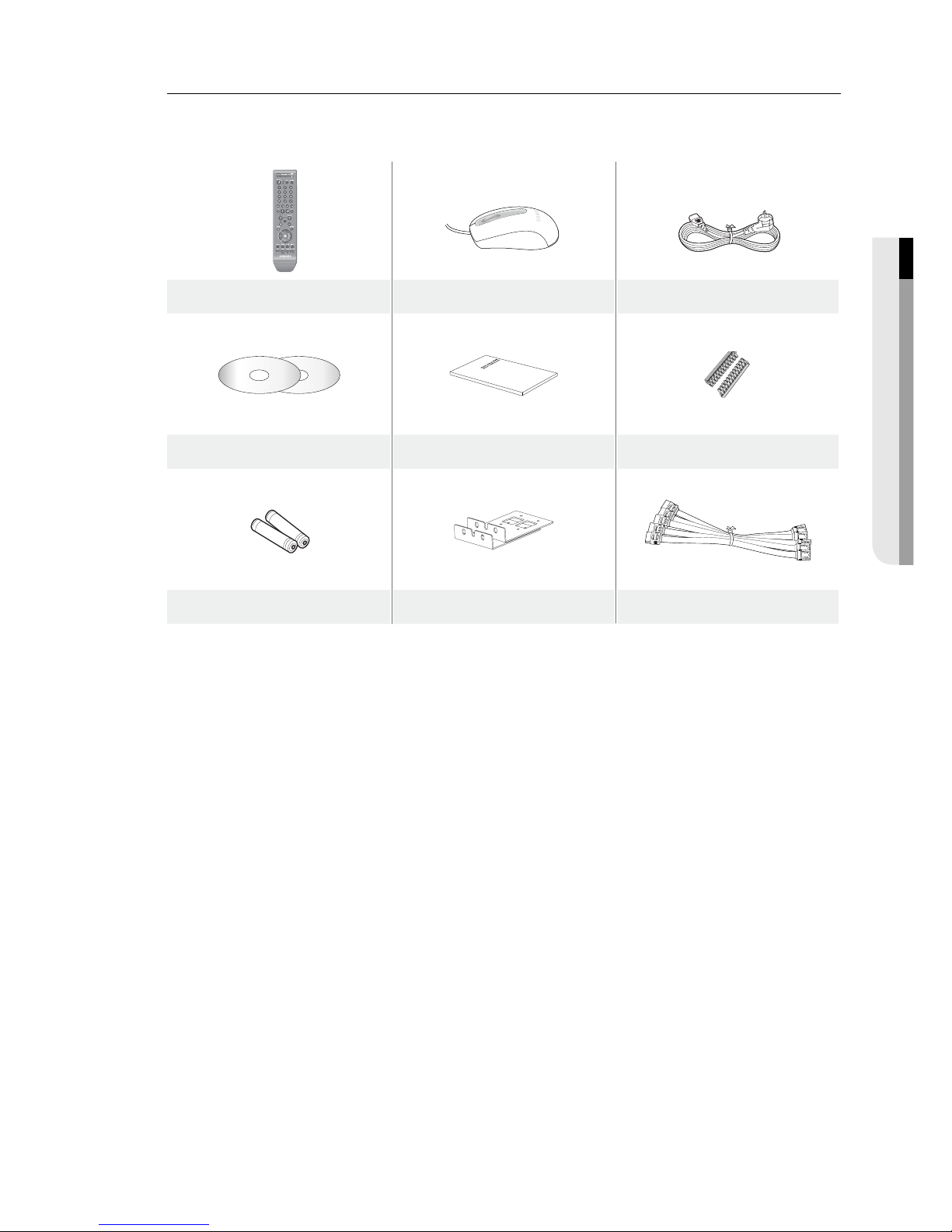
Package Contents
Please unwrap the product, and place the product on a fl at place or in the place to be installed.
Please check the following contents are included in addition to the main unit.
Remote Control Mouse Power Cable
NET-i Pro Software / User’s Manual CD User’s Manual RS-485 connector port
Remote Control Battery (AAA) Bracket Rack SATA Cable

6_ overview
overview
CONTENTS
OVERVIEW
2
2 Features
3 Important Safety Instructions
4 Before Start
6 Contents
8 Part Names and Functions (Front)
10 Part Names and Functions (Rear)
12 Remote Control
INSTALLATION
14
14 Checking the Installation Environment
15 Rack Installation
15 HDD Addition
CONNECTING WITH OTHER DEVICE
19
19 Connecting the Video, Audio, and Monitor
19 Connecting the Network
20 Connecting the USB
20 Connecting POS Device
21 Connecting the Alarm Input/Output
22 Connecting the RS-485 Device
LIVE
23
23 Getting Started
25 Live Screen Configuration
29 Live Mode
31 Spot Out
32 Zoom
32 Audio On/Off
32 Freeze
33 Event Monitoring
USING THE DVR
34
34 System Setup
42 Setting the Device
50 Setting the Recording
53 Setting the Event
56 Backup
57 Network Configuration
64 Controlling a PTZ Device
SEARCH & PLAY
66
66 Search
69 Playback

English _7
OVERVIEW
WEB VIEWER
70
70 Introducing Web Viewer
71 Connecting Web Viewer
73 Using Live Viewer
79 Using Search Viewer
83 Viewer Setup
93 About
BACKUP VIEWER
94
94 SEC Backup Viewer
APPENDIX
96
96 Product Specification
99 Product Overview
100 Default Setting
103 Troubleshooting
105 Open Source License Report on the Product
8_ overview
overview
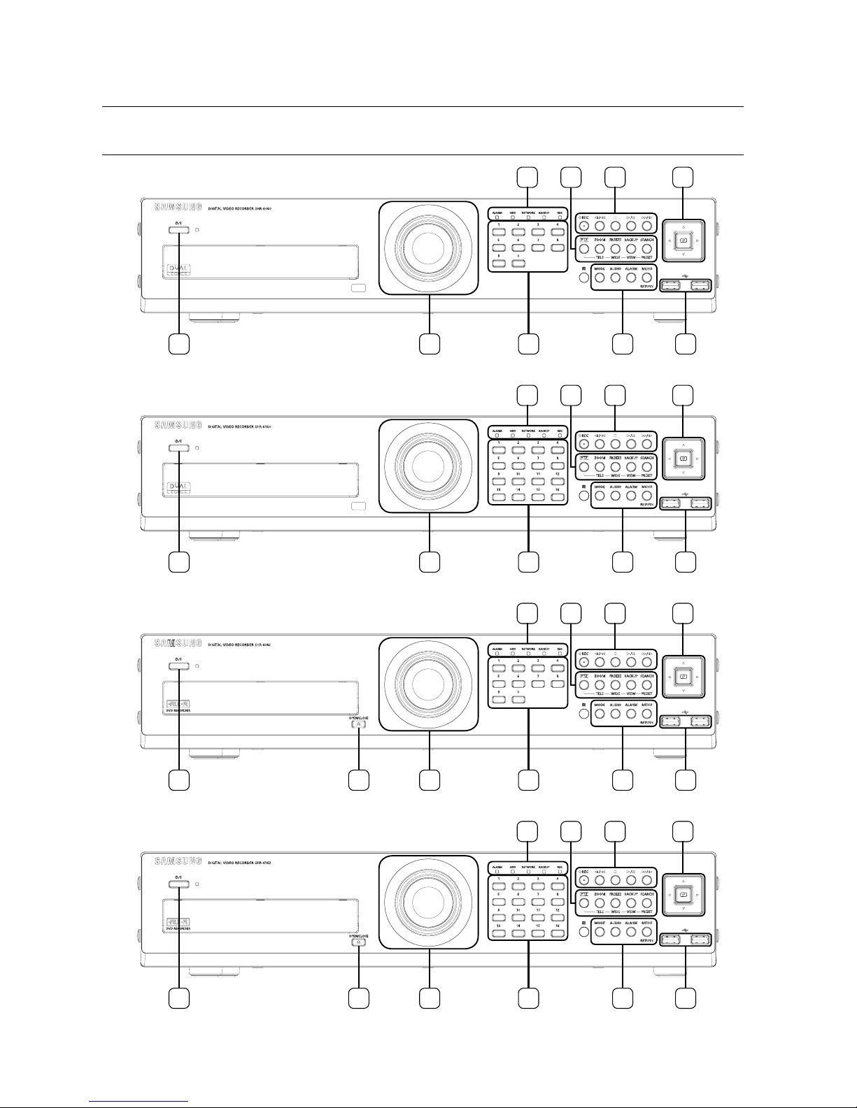
PART NAMES AND FUNCTIONS (FRONT)
6080
1 3 4
7
10
6 5
2
8
6160/6163
1 3 4
7 6 5
2
8
10
1 3 4
7
10
6 5
2
9 8
6082
1 3 4
7 6 5
2
9 8
10
6162/6164
English _9
OVERVIEW
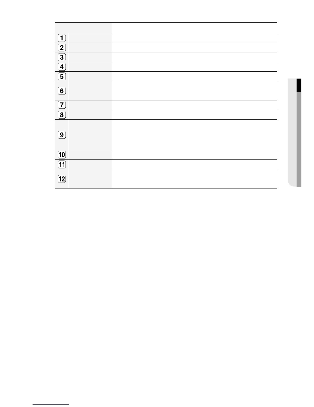
Part Names Functions
LED Indicator
ALARM : Lights on when an event occurs.
HDD : Displays the normal access to HDD.
Upon access to HDD, LED repeats on and off.
NETWORK : Displays both network connection and data transfer status.
BACKUP : Displays when Backup is in progress.
REC : Lights on when recording is in progress.
Camera Control
PTZ : Sets PTZ Mode ON/OFF.
ZOOM(TELE) : Sets the screen to the x2 digital zoom.
Runs the TELE function in the PTZ Mode.
FREEZE(WIDE) : Runs the FREEZE function in the Live Mode.
Runs the WIDE function in the PTZ Mode.
BACKUP(VIEW) : Runs the BACKUP function.
Runs the Preset View function in the PTZ Mode.
SEARCH(PRESET) : Goes to the search screen.
Runs the Preset Setup function in the PTZ Mode.
REC Starts or ends the recording.
/
Step Rewind (
) : Used for backward frame-by-frame search while in PAUSE.
Fast Rewind () : Used for quick backward search while in Play.
(-x2,-x4,-x8,-x16,-x32,-x64)
STOP : Used to stop the playback.
►/
PLAY/PAUSE : Used to pause or resume the screen.
/
Fast Forward () : Used for quick forward playback. (x2, x4, x8, x16, x32, x64)
Step Forward (
) : Used for forward frame-by-frame search while in PAUSE.
Direction &
Select Button
Used to change a value or move the cursor up/down/left/right (▲▼◄ ►).
Selects a menu item or executes the selected menu.
USB Port 1 & 2 Connects the USB devices.
MODE
Each button press in the Live Mode switches the screen to 16-, 9-, 4-, 6-, 8-, 13- split screen,
PIP, and auto sequence mode in order.
In play mode, each press of the button will switch the screen mode to 13-, 1-, 4-, 9-, and 16split in order. (1 live channel + (N-1) live channel)
AUDIO Sets Audio ON/OFF.
ALARM
Cancels the ALARM LED and the audible alarm when the alarm is going off, and to remove the
icon.
MENU/RETURN Either goes to the system menu screen or moves to the upper menu from the lower menu.
Channel
Used to select channel numbers directly in the Live Mode, or numbers in the numeric input
mode.
Jog shuttle
When a scroll bar appears in each menu, acts as a scrolling.
In Play mode, - Jog : Pauses the playback and steps backward or forward.
- Shuttle : Fast playback forward or backward.
OPEN/CLOSE Used to open and close the DVR-RW disc tray. (available for SHR-6082/6162/6164 only)
Power
Power LED : Displays the power ON/OFF status.
Power Button : Used to turn the DVR ON/OFF.
10_ overview
overview
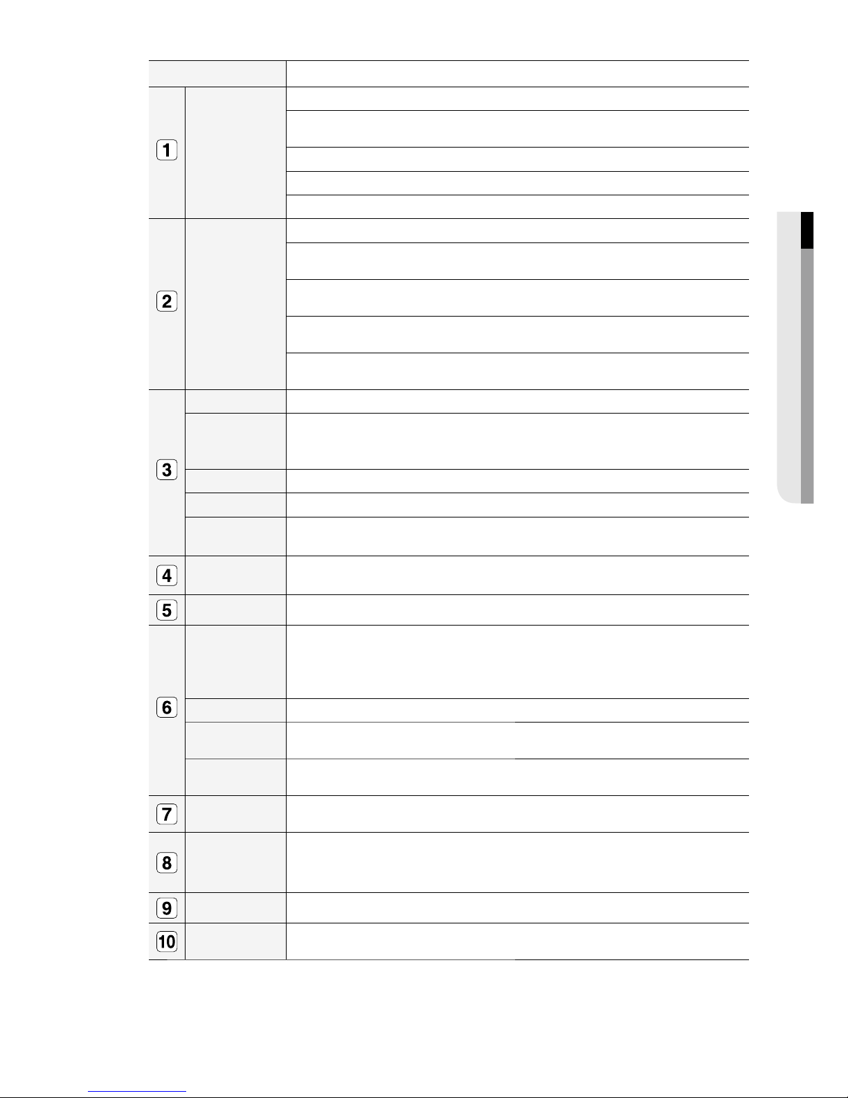
PART NAMES AND FUNCTIONS (REAR)
6080/6082
6160/6162/6163/6164
1 2 3 4 5 7 8 9 10 12116
132
4 5 7 8 9 10 12116
English _11
OVERVIEW
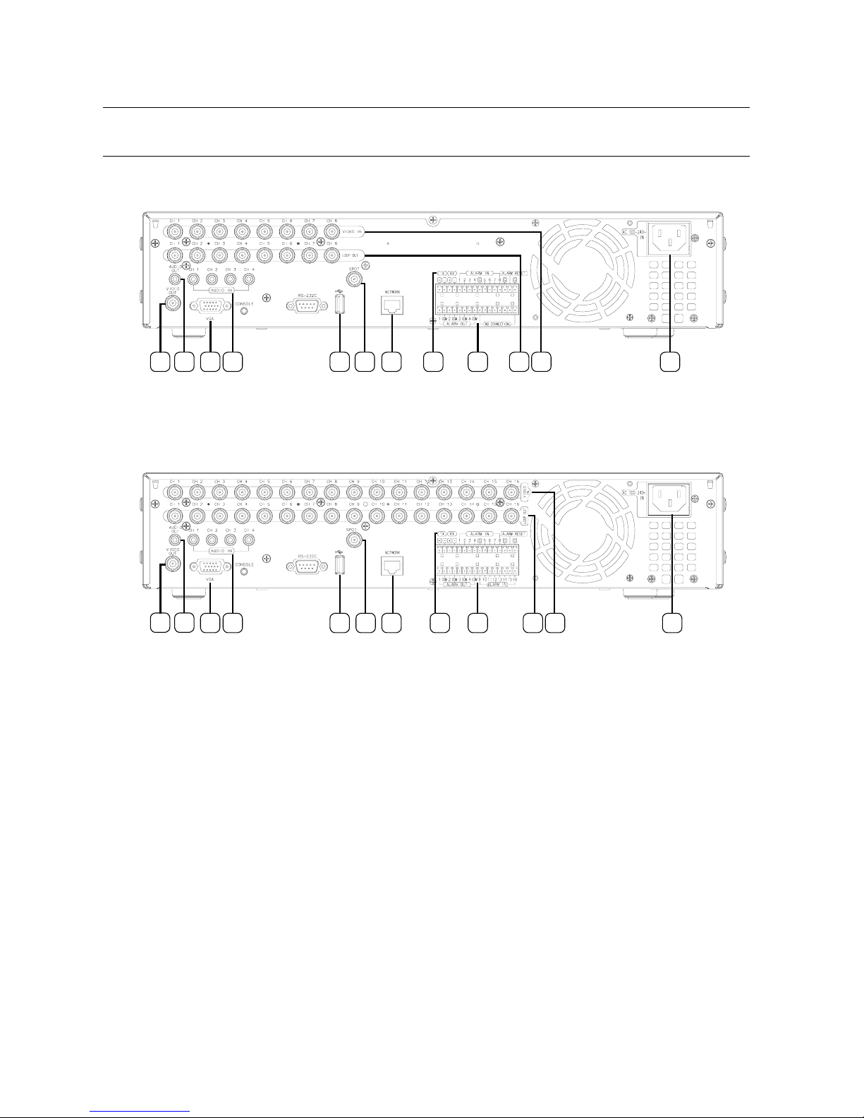
Part Names Functions
VIDEO OUT Composite Video Signal Output Port (BNC type connector).
AUDIO OUT Audio Signal Output Port (RCA jack).
VGA VGA Video Signal Output Port.
AUDIO IN Audio input signal port (RCA Jack).
USB USB connector port.
SPOT
A live screen output port, separate from the VIDEO OUT.
Supports Single, 4-, 9-, 16-split, and Auto Sequence modes
NETWORK NETWORK connector port.
RS-485 Used for RS-485 communication. (TX+, TX-, RX+, RX-)
ALARM
- ALARM IN 1~16(SHR-6160/6162/6163/6164): Alarm Input port.
- ALARM IN 1~8(SHR-6080/6082): Alarm Input port.
- ALARM RESET IN: Alarm Reset port.
- ALARM OUT 1–4: Alarm Output port.
LOOP OUT Used to transfer a video signal to other video devices.
VIDEO IN Composite Video Signal Input Port (BNC type connector).
AC 100-240V~ IN
AC 100 ~ 230V (PAL)
AC 110 ~ 220V (NTSC)
12_ overview
overview
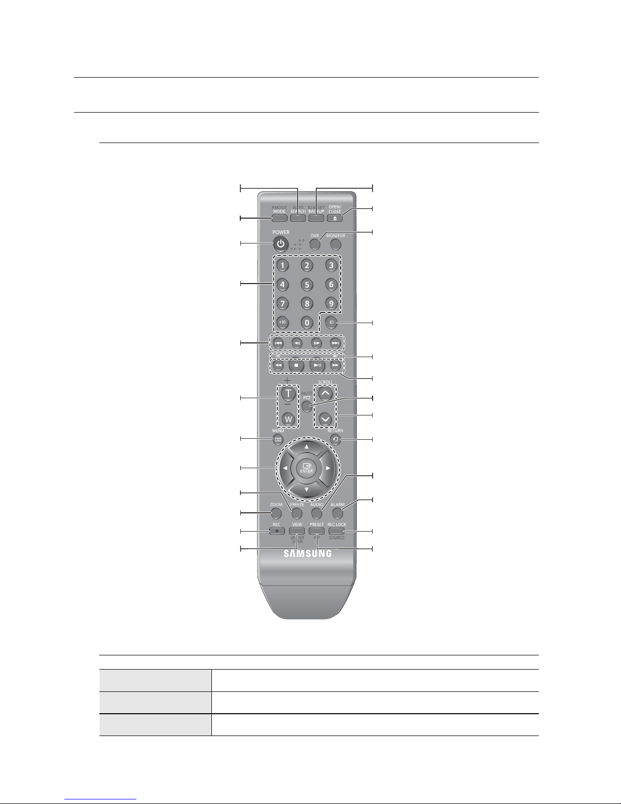
REMOTE CONTROL
DVR
Available after switching to DVR mode by pressing the [DVR] button on the remote control.
Using the numeric buttons
CHANNEL 1–9 Press each button between 1 to 9.
CHANNEL 10 Press the [+10] button fi rst, then press the 0 button again within 3 seconds.
CHANNEL 11–16 Press the [+10] button fi rst, then press any number between 1 to 6 within 3 seconds.
SEARCH
Displays the search menu
.
POWER
Displays the Exit pop up screen.
NUMBER [0~+10]
Used as the numeric input keys, or displays a single
channel.
T/W
Zooms in or out.
BACKUP
Displays the Backup Menu.
MODE
Changes the screen mode.
MENU
Goes to the system menu screen.
Up/Down/Left/Right(▲▼◄ ►)/ENTER
Moves the cursor up/down/left/right, and runs the
Select Menu.
FREEZE
Freezes the screen temporarily.
ZOOM
Runs the digital zoom (x2) function.
VIEW
Runs the View function in the PTZ mode.
OPEN/CLOSE
Opens or closes the CD tray.
DVR
Activates the DVR function.
ID
Sets the ID of the system.
Select 2 digits from 0 ~ 9 while pressing the ID Key.
PTZ
Displays or ends PTZ.
SCROLL ,.
Moves the menu scroll.
RETURN
Returns to the previous screen.
AUDIO
Turns Audio on/off.
ALARM
Cancels the Alarm.
REC LOCK
Selects the recording lock function.
PRESET
Displays the Preset Setup.
REC
Starts or ends the live recording.
Skip Backward (by unit time),
Slow Rewind, Slow Forward,
Skip Forward (by unit time)
Move Frame
While paused, moves to the previous/next frame.
FR, STOP, PLAY/PAUSE, FF
English _13
OVERVIEW
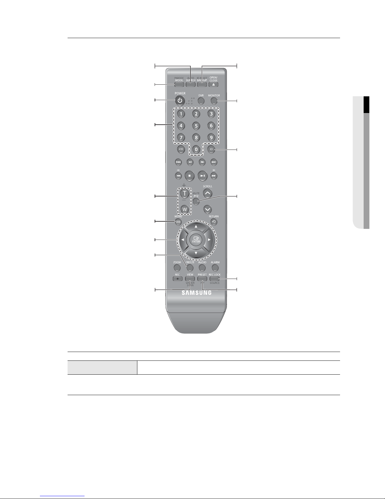
MONITOR
Available after switching to Monitor mode by pressing the [MONITOR] button on the remote control.
Using the Numeric buttons
CHANNEL 1–9 Press any button among 1 to 9.
Changing the Remote Control ID
Press the ID button of the remote control and check the ID displayed on the DVR screen.
The factory default ID of the remote control is 00.
Enter 2 digits of your selection in order, while pressing the system [ID] button.
When ID input is done, press the system [ID] button again to check the setting.
If you want to change the remote control ID to 08: Press 0 and 8 in order while the system [ID] button is pressed.
Remote control's ID and DVR’s ID should be matched for proper operation. Refer to “Remote Devices”. (Page 46)
1.
2.
3.
M
AUTO
Selects the screen status automatically.
POWER
Turns the monitor power on/off.
NUMBER [0~9]
Changes the system ID.
+/-
Adjusts the audio volume.
ID RESET
Initializes the ID value to 01.
P.MODE
Selects the screen mode.
MENU
Displays the Setup Menu.
Up/Down/Left/Right(▲▼◄ ►)/ENTER
Moves the cursor up/down/left/right, and runs the
Select Menu.
FREEZE
Screen Freeze.
UNDER SCAN
Displays the video screen within a screen.
MONITOR
Activates the monitor function.
ID
Sets the ID.
Select 2 digits from 0 ~ 9 while pressing the ID Key.
MUTE
Mutes the audio out.
SOURCE
Selects the input signal source.
PIP
Selects or deselects the PIP function.
14_ installation
installation
Please be noticed with the followings before you use the product.
Do not use the product outdoor.
Do not spill water or liquid in the connection part of the product.
Do not impose the system to excessive shock or force.
Do not pull out the power plug forcefully.
Do not disassemble the product on your own.
Do not exceed the rated input/output range.
Use a certifi ed power cord only.
For the product with an input ground, use a grounded power plug.
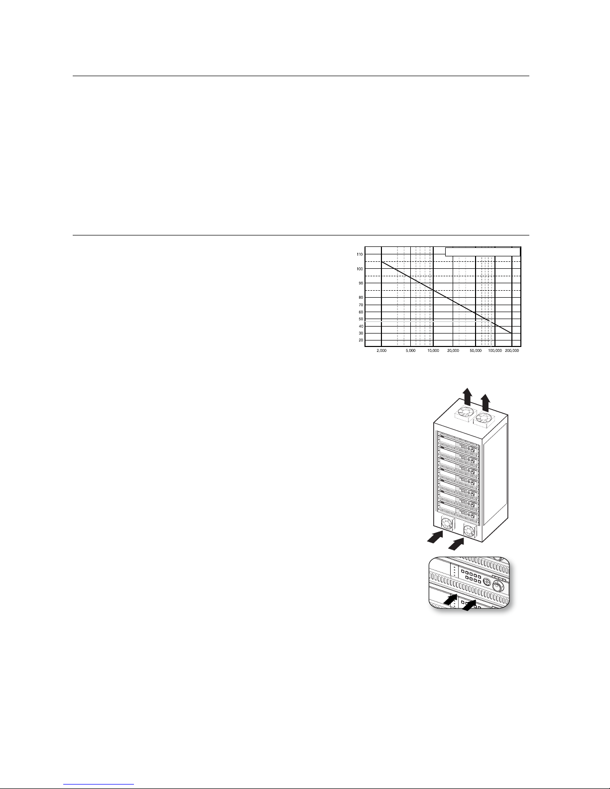
CHECKING THE INSTALLATION ENVIRONMENT
Samsung Digital Video Recorder (“DVR” hereinafter) is a
state-of-art security device, and contains mass storage
hard disk(s) and critical circuits inside.
When the temperature rises inside the product, the product
may breakdown and the product life be shortened. Please
pay attention to the following recommendations before
installation.
The followings are the recommendations when Samsung DVR is installed on a rack.
Please ensure that the rack inside is not sealed.
Please ensure the air is circulated through the inlet/outlet as shown in the picture.
If the DVR or other devices on a rack is to be stacked as in the picture, provide a
suitable space or install a ventilating opening for air circulation.
For natural air convection, place the inlet at the bottom of the rack and the outlet on
top.
It is strongly recommended that a fan motor is installed at the inlet and the outlet for
air circulation. (Please fi t a fi lter at the inlet to screen dust or foreign substances.)
Please maintain the temperature inside the rack or surrounding areas between 0°C
~ 40°C (32°F ~ 104°F) as shown in the fi gure 1.
•
•
•
•
•
•
•
•
•
•
1.
2.
3.
4.
5.
6.
One Year: 24HR X 365 DAY =8,760 HR
Temperature
Unit: ºC
Life (Unit: HOURS)
[Figure 1]
[Figure 2]
English _15
INSTALLATION
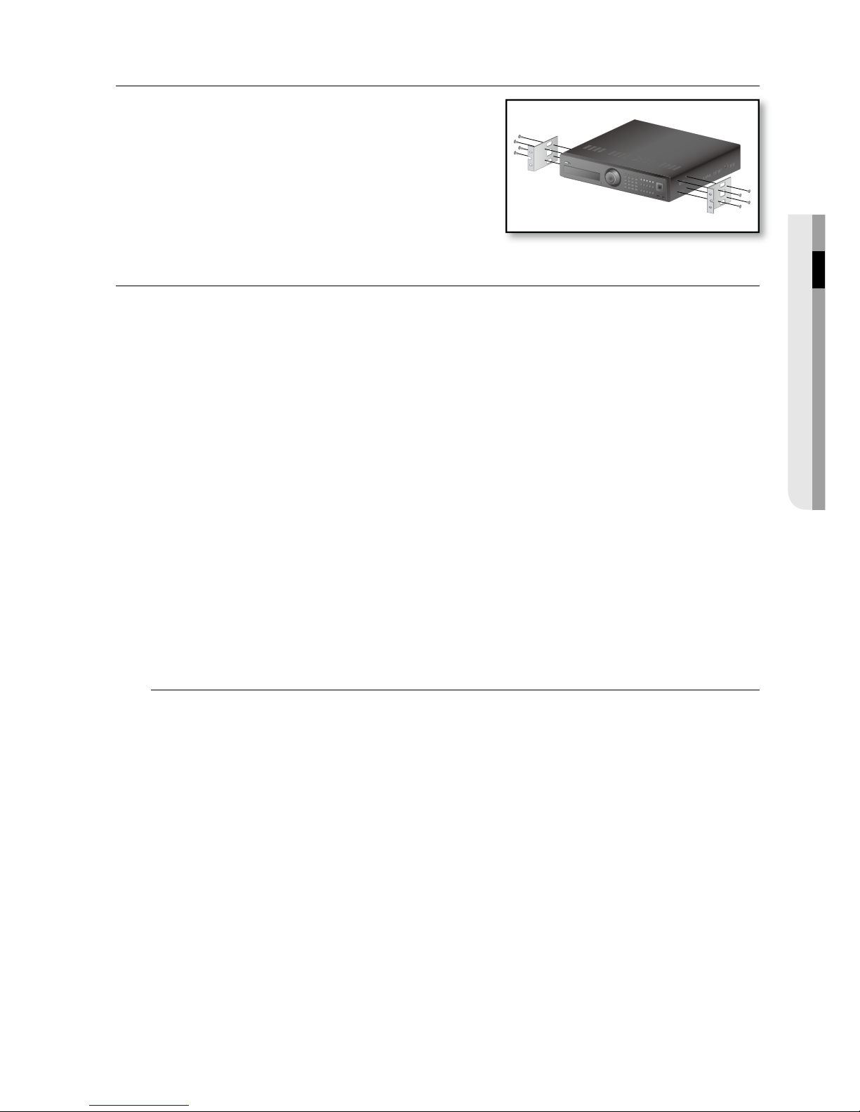
RACK INSTALLATION
Loosen the screws on both sides (4 screws on each side) and install
the Bracket-Rack as shown in the fi gure, and then fasten the screws
on both sides (4 screws on each side).
Fix the screws not to be loosened by vibrations.
HDD ADDITION
You can install additional HDDs.
Make sure to unplug the power cord from the wall outlet to prevent possible electric shock, injury or product
damage.
Please consult your provider for further information on HDD installation since improper installation or settings may
damage the product.
Number of HDDs supported : SHR-6082/6162/6164: Default 1 HDD + Up to 4 HDDs added
SHR-6080/6160/6163: Default 1 HDD + Up to 5 HDDs added
Cautions for data loss (HDD care)
Please pay attention so that the data inside the HDD is not damaged.
Before adding a HDD, please check the compatibility with this DVR product.
HDD is vulnerable to malfunction due to its sensitive nature against externalities or shocks during operation. Please
ensure that the HDD is free from such shock or externalities.
We are not liable for any damage to the HDD incurred by user’s carelessness or externalities.
Cases might cause damage to HDD or recorded data
To minimize the risk of data loss from a damaged HDD, please backup data as often as possible.
Data may be lost due to external impacts during disassembly or installation of the DVR.
HDD may be damaged if the DVR is suddenly stopped by a power cut or power off during operation.
HDD or fi les stored inside may be damaged if the main body is moved or impacted during the HDD operation.
Cautions when adding a HDD
When adding a HDD, pay attention so that the cable does not get caught between unsuitable spaces or
the cable’s insulation does not come off.
Pay attention so as not to lose the disassembly screws or accessories.
If the screws or accessories are not put together, the product may breakdown or not operate properly.
Please check the HDD compatibility before adding a HDD.
Please contact your nearest dealer to obtain the list of compatible devices.
J
1.
2.
3.
16_ installation
installation
Adding a HDD
Make sure to unplug the power cord from the wall outlet before proceeding with the installation.
Number of HDDs to install : SHR-6082/6162/6164 : Default 1 HDD + Up to 4 HDDs added
SHR-6080/6160/6163 : Default 1 HDD + Up to 5 HDDs added
By factory default, the unit is equipped with one HDD.
The following instructions are when you have installed the maximum number of HDDs on the master unit.
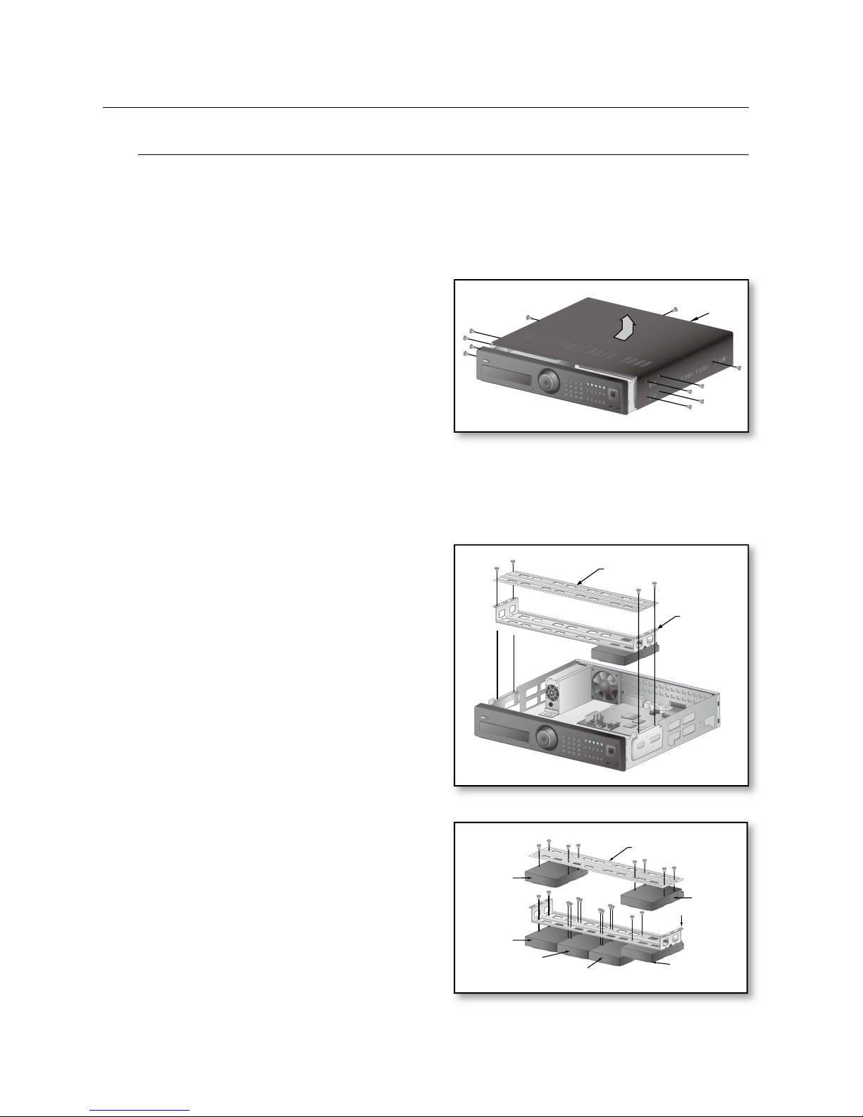
First, loosen the screws in the left and right sides
and remove the cover.
1) If adding HDDs to SHR-6080, 6160& 6163
For SHR-6082/6162/6164 models, see the following page.
Loosen the screws (x4) in the left/right and upper
sides and remove the upper and lower brackets.
Install HDDs (x3) on the lower bracket and fi x them
with screws.
The screw (UNC 6-32) to use in the installation comes with
the HDD.
Firmly secure the screw so that it can not get loose from
such as vibration.
Install HDDs (x2) on the upper bracket and fi x them
with screws.
M
1.
M
2.
3.
4.
Cover
Upper Bracket
Lower
Bracket
Lower Bracket
Upper Bracket
Add
Installed by
default
Add
Add
Add
Add
English _17
INSTALLATION
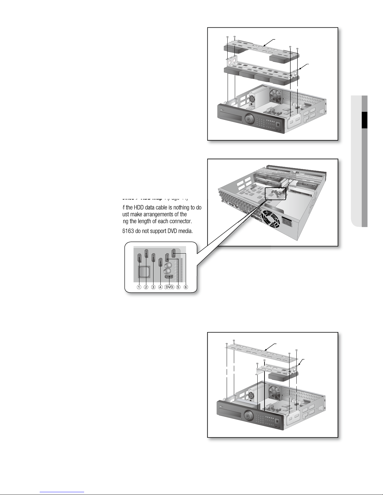
When the installation of additional HDDs is done,
insert the lower and upper brackets into the DVR
and fi x them with the provided screws.
When the installation of additional HDDs is done,
connect the power cable and connect the HDD
signal cables (SATA Cable) to connectors ~ on
the main board.
You can check the HDD map directly on the DVR.
Refer to “Storage Device > HDD Map”. (Page 44)
Note that the order of the HDD data cable is nothing to do
with the operation. Just make arrangements of the
connectors considering the length of each connector.
SHR-6080, 6160 & 6163 do not support DVD media.
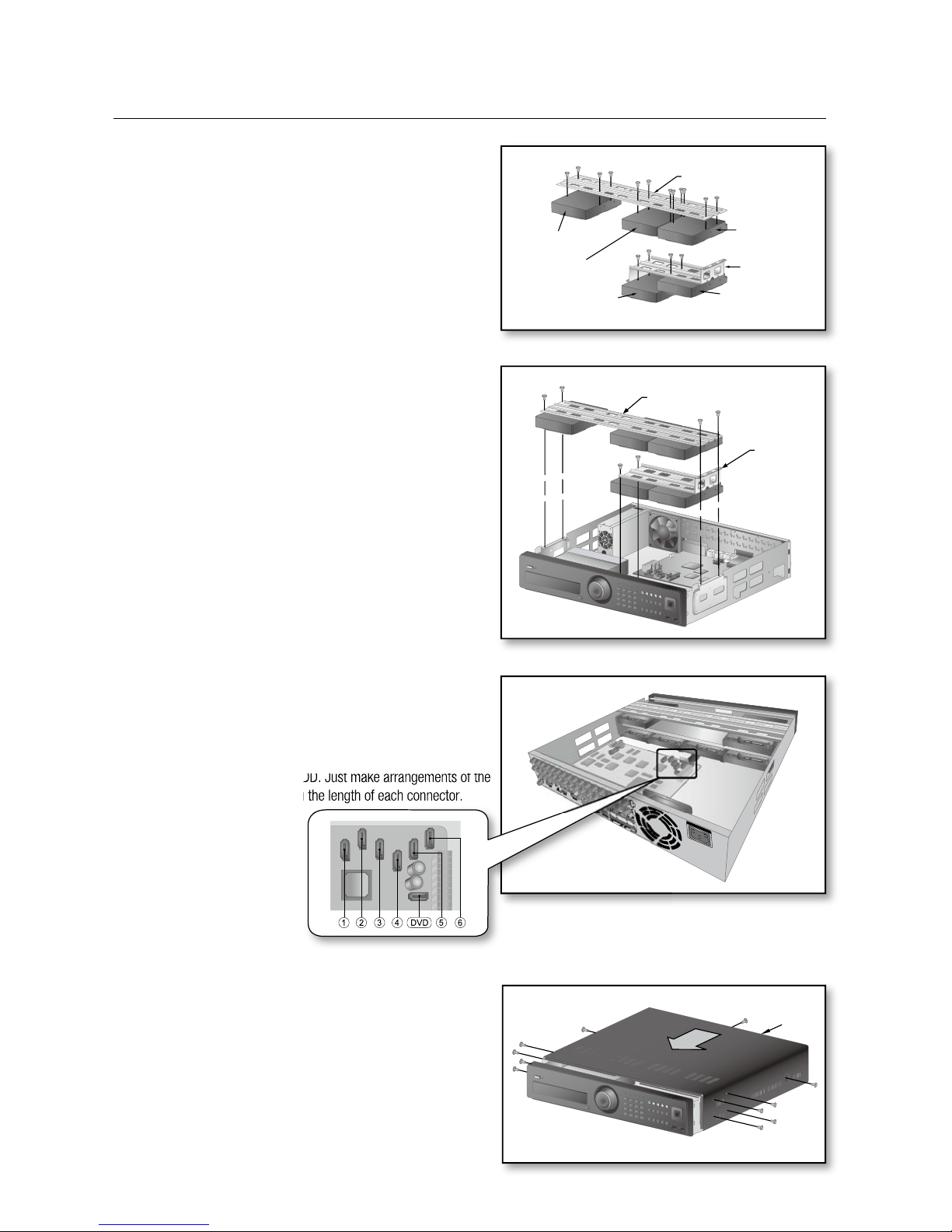
2) If adding HDDs to SHR-6082, 6162 & 6164
Loosen the screws (x4) in the left/right and upper
sides to remove the upper bracket and loosen the
lower screws (x2) to remove the lower bracket.
5.
6.
2.
Upper Bracket
Lower
Bracket
Upper Bracket
Lower Bracket
18_ installation
installation
Install a HDD (x1) on the lower bracket and fi x it with
screws.
Install HDDs (x3) on the upper bracket and fi x them
with screws.
When the installation of additional HDDs is done,
insert the lower and upper brackets into the DVR
and fi x them with the provided screws.
When the installation of additional HDDs is done,
connect the power cable and connect the HDD
data cables (SATA Cable) to connectors ~ on
the main board.
Note that the number of a HDD data calbe is nothing to do
with operation of the HDD. Just make arrangements of the
connectors considering the length of each connector.
Check if the connectors are properly connected and
there is no problem with wiring, and close the cover
and fi x it with screws.
3.
4.
5.
6.
7.
Cover
Upper Bracket
Lower
Bracket
Lower Bracket
Upper Bracket
Add
Installed by default
Add
Add
Add
English _19
CONNECTING WITH OTHER DEVICE
connecting with other device
The following fi gures are based on Model SHR-6164.
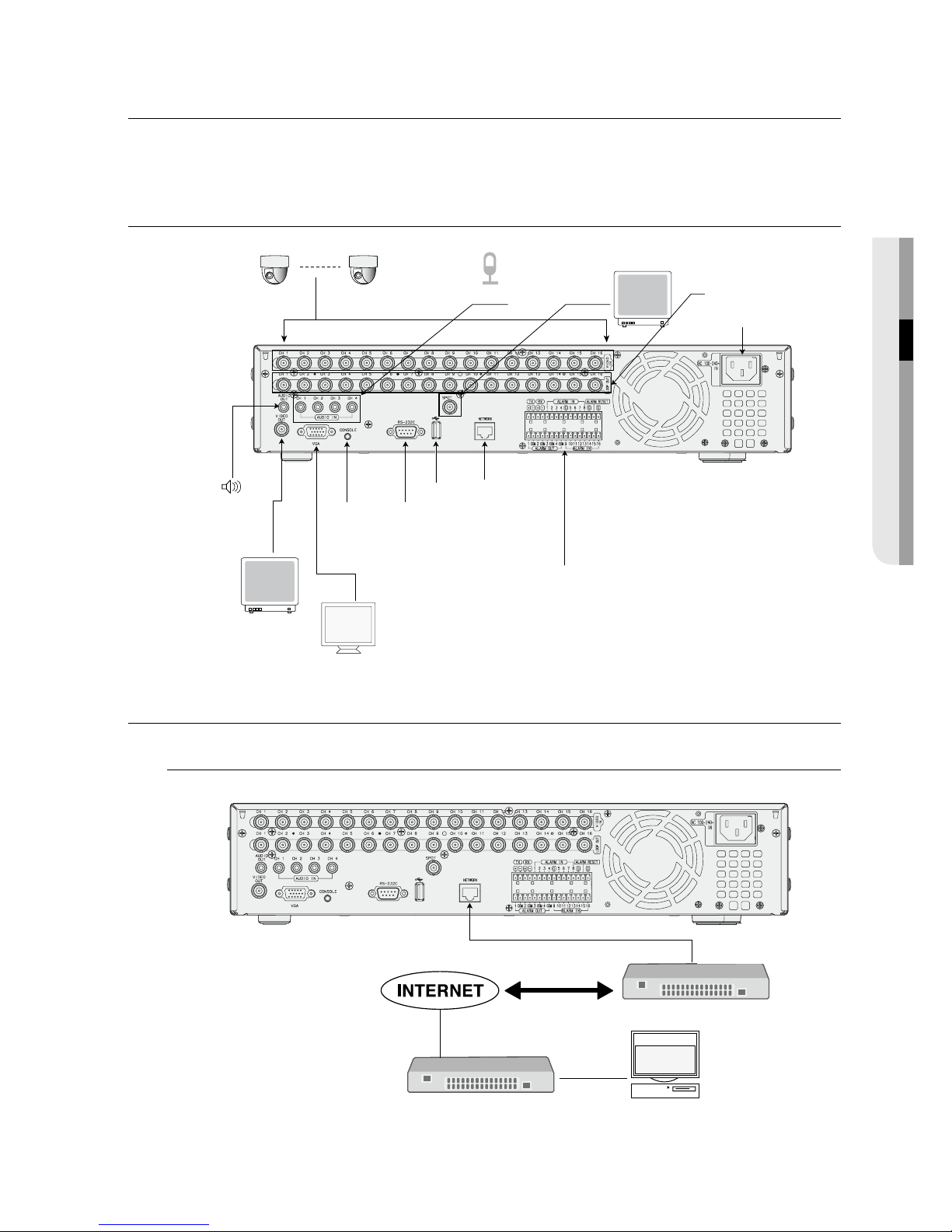
CONNECTING THE VIDEO, AUDIO, AND MONITOR
CONNECTING THE NETWORK
Connecting to Internet through Ethernet (10/100/1000BaseT)
M
VIDEO IN
AUDIO IN SPOT
AC 100-240V~IN
RS-485 / ALARM
USB 2.0
VIDEO OUT
(VGA)
VIDEO OUT
(composite)
AUDIO OUT
NETWORK
RS-232CONSOLE
LOOP OUT
Windows
NET-i Pro
Back Bone
Hub/Switcher
Hub/Switcher
RJ-45 Ethernet Cable
(Direct Cable)
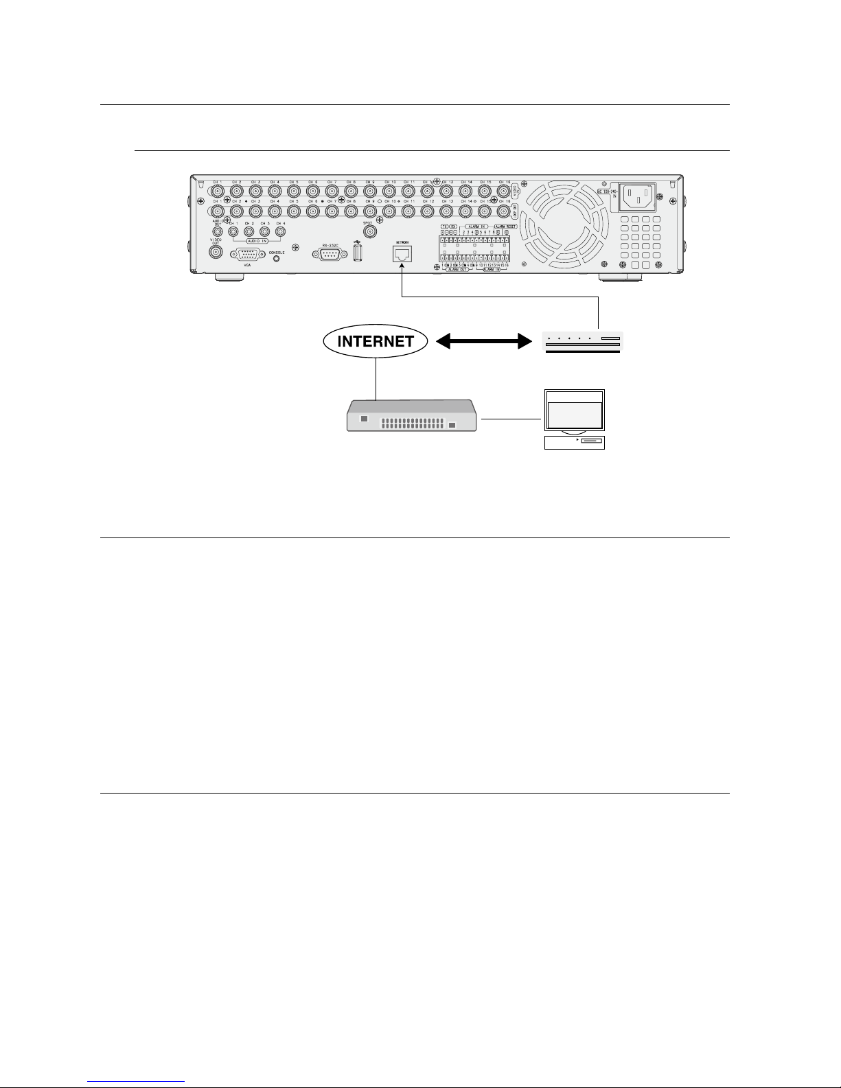
20_ connecting with other device
connecting with other device
Connecting to Internet through ADSL
CONNECTING THE USB
There are two USB ports at the front and one at the back of the product.
You can connect a USB HDD, USB CD/DVD player, USB memory or mouse to the USB port.
If a USB HDD is connected to the system, recognition and settings are available in “Menu > Setting the Device >
Storage Device”. (Page 44)
This product supports hot-plugging, which connects/removes the USB device during the system operation.
The USB type HDD must be set as Master.
If you use the USB device for Backup purposes, format it with FAT32 on PC if it is not formatted on the DVR.
CONNECTING POS DEVICE
You can connect a POS device to the RS-232C port on the product’s rear side when you connect it directly with
a RS-232C cable.
Connection setup for the RS-232C port is available in “Menu > Device > POS Devices”, press the
<POS Device Setup> button and set <Baud rate, Parity, Data, Stop bit and Transfer Type>. (Page 46)
1.
2.
3.
4.
J
1.
2.
Hub/Switcher
Phone(ADSL) Line
ADSL MODEM
RJ-45 Ethernet Cable
(Direct Cable)
Windows
NET-i Pro
English _21
CONNECTING WITH OTHER DEVICE
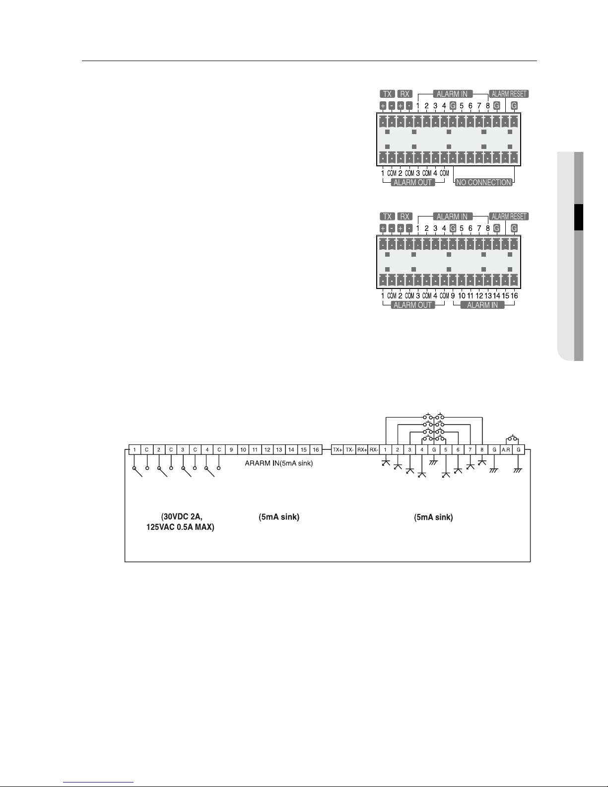
CONNECTING THE ALARM INPUT/OUTPUT
The Alarm In/Out port at the back is composed of the following.
Alarm In/Out Port on 6080/6082
Alarm In/Out Port on 6160/6162/6163/6164
ALARM IN 1 ~ 8 (SHR-6080/6082) : Alarm Input Port
ALARM IN 1 ~ 16 (SHR-6160/6162/6163/6164) : Alarm Input Port
ALARM RESET : On receiving an Alarm Reset signal, the system cancels the current Alarm Input and resumes
sensing.
ALARM OUT 1 ~ 4 : Alarm Output Port
1.
2.
•
•
•
•
ALARM OUT ALARM IN ALARM IN
22_ connecting with other device
connecting with other device
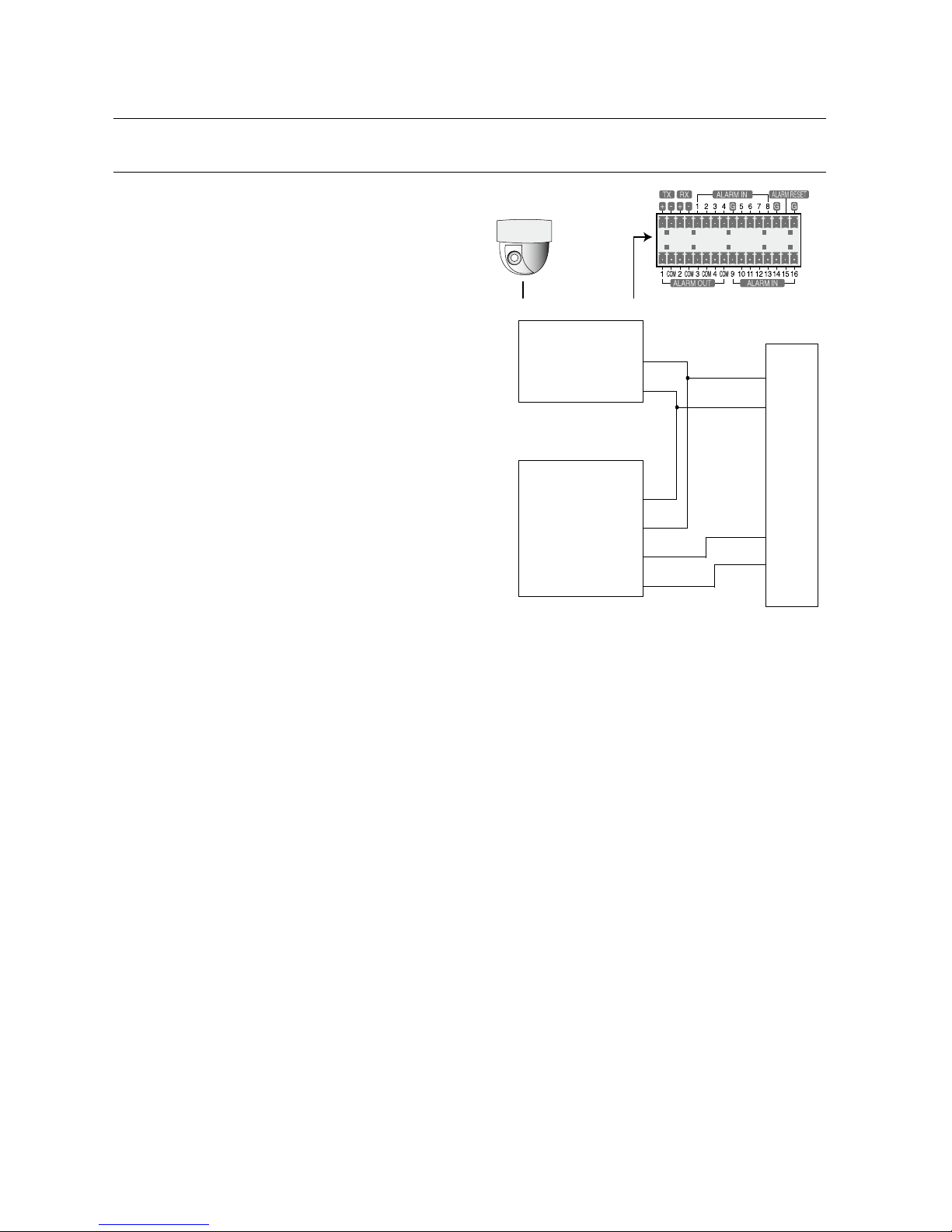
CONNECTING THE RS-485 DEVICE
Connect the RS-485 device through the back port.
For example, you can connect and control the PTZ
camera which supports the RS-485
communication.
Transfer Type : You may select either Half Duplex or Full
Duplex as the data transfer type.
Baud Rate : Supported Baud rates are 600/1200/2400/
4800/9600/19200/38400.
Check if the RS-485 device is compatible with the
product fi rst.
Pay attention not to change the polarity (+/-) of the
RS-485 device when connecting it.
Depending on camera’s type, connection polarity can be
different.
For further information, refer to the respective PTZ
Camera’s documentation.
Ex : DVR(TX+/-) ↔ SCC-C6433,35(RX+/-)
DVR(TX+/-) ↔ SCC-C6403,07(TX+/-)
M
•
•
M
PTZ device
Half Duplex Type
Data (–)
Data (+)
Full Duplex Type
Rx(+)
Rx(–)
Tx(–)
Tx(+)
Rear
Tx(–)
Tx(+)
Rx(–)
Rx(+)
English _23
LIVE
live
GETTING STARTED
Starting the system
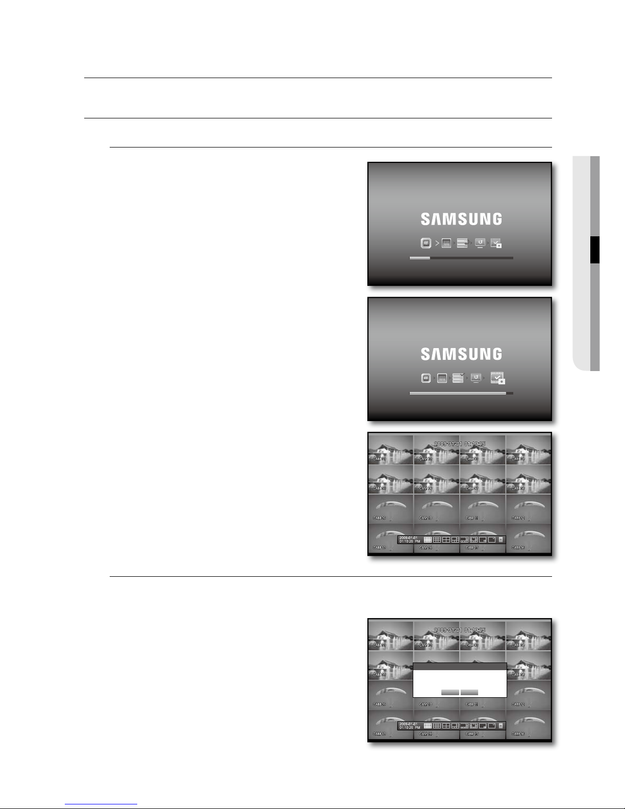
Connect the power cable of the DVR to the wall outlet.
Press the Power button on the front panel.
You will see the initialization screen.
The initialization process will last about 1 minute in the
order of icons appeared.
If a new HDD is installed, the initialization process may take
a longer time.
The live screen appears with a beep.
Shutting Down the System
You can shut down the system only if you have logged in to the DVR.
You should have the <Shutdown> permission to shut down the system if you are not an admin.
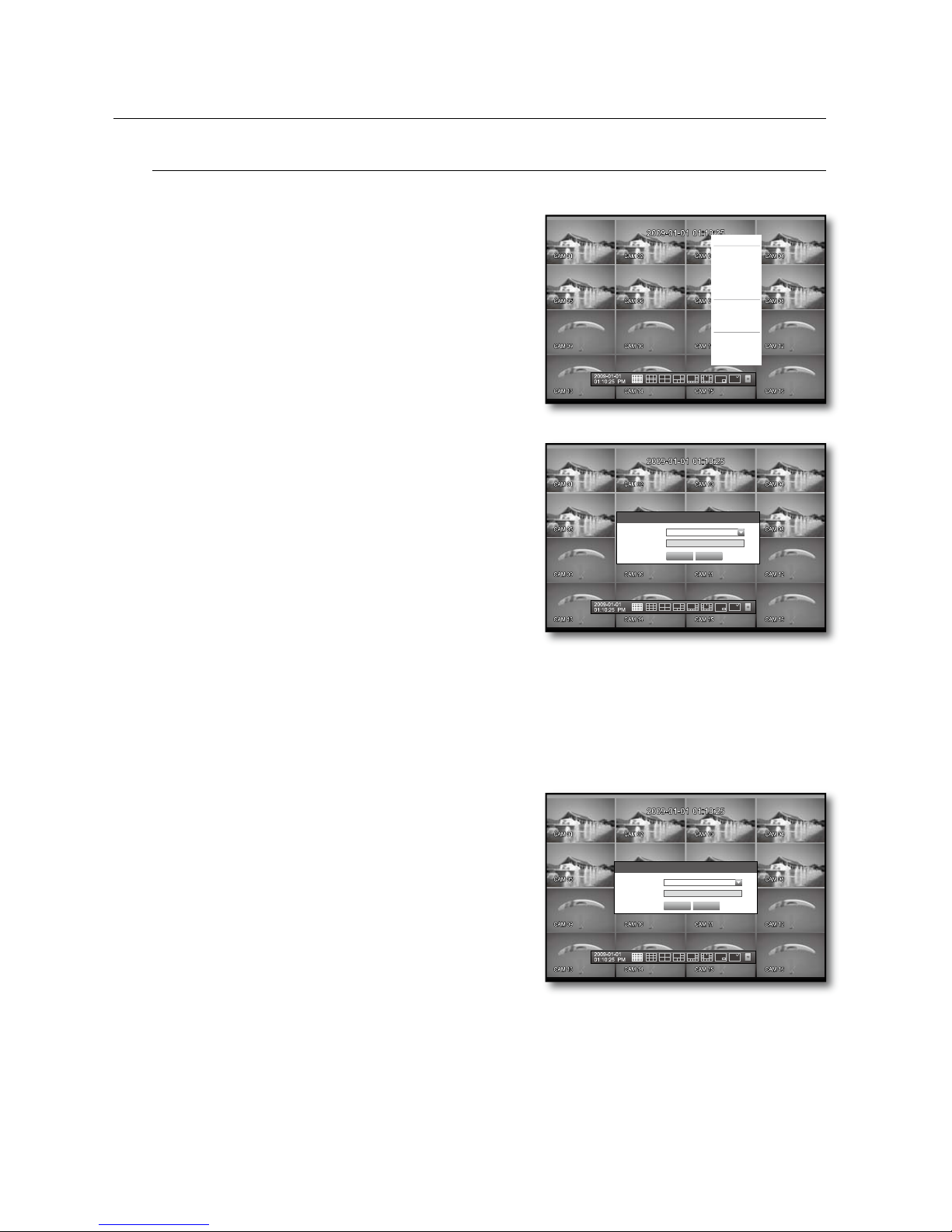
Press the [POWER] button on the remote control or the
front panel, or right-click to display the context sensitive
menu and select <Shutdown>.
The “Shutdown” confi rmation window appears.
Use the arrow keys on the remote control or the front panel
to move to <OK> and press the [ENTER] button or click
<OK>.
The system will shut down.
For the permission management, refer to “Permission
Management > Setting Permissions”. (Page 38)
1.
2.
3.
4.
1.
2.
3.
M
Shutdown
Are you sure to shutdown?
OK Cancel
24_ live
live
Login
To access a DVR or restricted menu, you should have logged in to the DVR.
In live mode, right-click any area of the screen.
You will see the context sensitive menu as in the right
fi gure.
Click <Login>.
The login dialog appears.
You can also see the login dialog to access a desired menu
by pressing the [MENU] button on the remote control or
the front panel.
The login dialog will also appear if you press a menu button on
the remote control or the front panel of the DVR when the
corresponding menu requires logging in.
For the restricted permission, refer to “Permission
Management > Setting Permissions”. (Page 38)
Locking All Buttons
This will restrict access to all buttons available in the DVR.
In Live mode, press buttons in the order of [STOP]
[FREEZE][STOP][FREEZE][MENU].
All buttons will be locked.
In the lock condition, press any button to display a dialog
where you are prompted to enter the password for
unlocking the buttons.
The button lock will be released if you enter the admin
password.
1.
2.
M
1.
2.
Login
ID admin
Password
OK Cancel
Scene Mode
Audio Off
Freeze
Stop Alarm
Record
Play
Search
Backup
Main Menu
Shutdown
Hide Launcher
Login
Key Lock Password
ID admin
Password
OK Cancel
English _25
LIVE
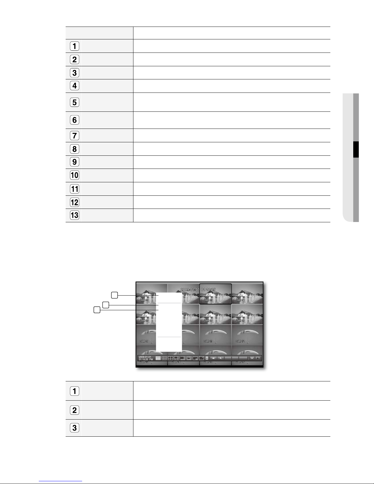
LIVE SCREEN CONFIGURATION
Icons on the Live Screen
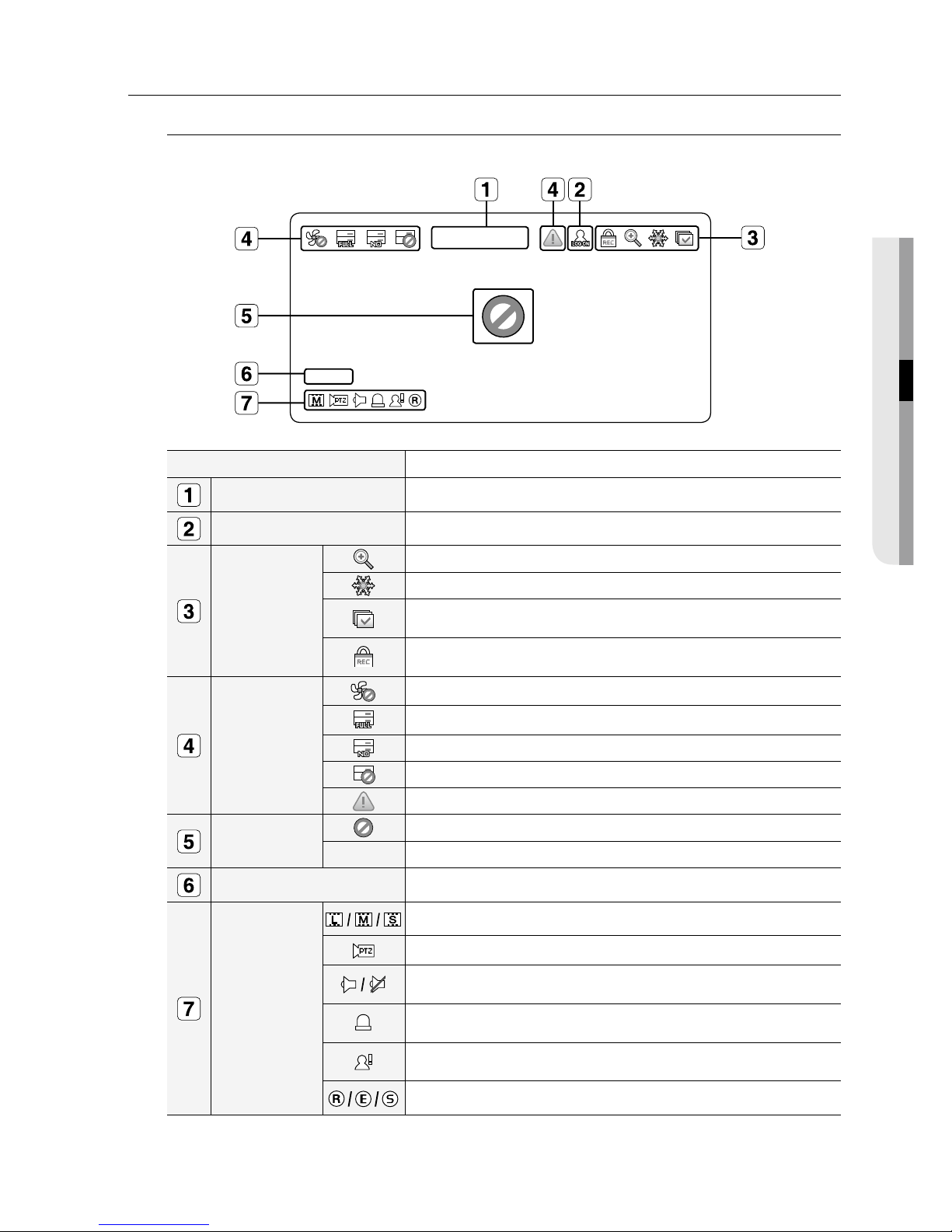
You can check the status or operation of the DVR with the icons on the live screen.
Name Description
Current Date, Time
Displays the current time and date.
Login Information
When you are logged in, the “LOG ON” icon will be displayed.
Screen Mode
Displayed if the zoom function is activated.
Displayed if you press the Pause button.
Displayed in Auto Sequence mode where all channels are switched at the
specifi c time interval.
Displayed if the recording is in process.
M To cancel the recording, enter the password.
System Operation
Displayed if there is a problem with the cooling fan.
Displayed if the HDD is full and the DVR has an insuffi cient space to record.
Displayed if no HDD is installed or the existing HDD should be replaced.
Displayed if the HDD needs a technical examination.
Displayed if a new fi rmware is found from the network.
Video Input Status
Displayed if no input is entered in the condition that the camera is set to <ON>.
Nothing will be displayed on the screen if the camera is set to <OFF>.
Camera Name/ Channel
Displays the camera name and the changed channel, if any.
Camera Operation
Displays the resolution of the recording screen. (Page 52)
Displayed in PTZ setting, and highlighted yellow if PTZ is in operation.
Displays AUDIO ON/MUTE.
Not displayed in video mode if deactivated.
If the sensor is set to <ON>, the input signal will be displayed on the screen of
the connected channel.
Displayed if a motion detected in the condition that the motion detection is set to
<ON>.
Displays the current record mode from Record/Event/Schedule.
2009-01-01 00:00:01
CAM 01
CAM 01
26_ live
live
Error Information
If you turn on the system in the condition that the internal HDD is not connected or an error occurs, the
“HDD FAIL” icon (
) will be displayed on the top left corner. In this case, make sure you contact the
service center for assistance as this may cause a failure of recording, playback or backup.
If the cooling fan does not work properly or has a problem, the <Fan Information> window will appear and
the fan error icon (
) will be displayed on the top left corner. In this case, check the internal fan for
operations.
As a fan error can shorten the product life, make sure you contact the service center for assistance.
If you see the fan error icon or No HDD, HDD FAIL icons on the screen, contact the service center for more details.
Live Screen Menu
In addition to the buttons on the front panel or the remote control, you can access a desired menu by rightclicking any area in live mode.
The context sensitive menu appearing by right-clicking the screen differs, depending on the login/logout,
screen split mode and DVD operation mode.
Menu items of Search, Record, Backup, Shutdown and PTZ can be deactivated, depending on the user permission.
Split Mode Menu
The context sensitive menu in split mode differs, depending on the login/logout status.
•
•
M
M
Scene Mode
Audio Off
Freeze
Stop Alarm
Record
Play
Search
Backup
Main Menu
Shutdown
Hide Launcher
Login
< Split Mode Menu >
< Single Mode Menu >
PTZ Alarm Freeze
Scene Mode
PTZ Control
ZOOM
Audio
Freeze
Stop Alarm
Record
Play
Search
Backup
Main Menu
Shutdown
Hide Launcher
Login
Scene Mode
Spot Out
Audio Off
Freeze
Stop Alarm
Record
Play
Search
Backup
Main Menu
Shutdown
Hide Launcher
Logout
2
13
12
11
10
9
8
7
6
5
4
3
1
English _27
LIVE
Menu Description
Scene Mode Refer to “Live Mode”. (Page 29)
Spot Out Refer to “Spot Out”. (Page 31)
Audio On/Off Refer to “Audio ON/OFF”. (Page 32)
Freeze Refer to “Freeze”. (Page 32)
Stop Alarm
Stops the alarm output and the event monitoring. Refer to “Event Monitoring”.
(Page 33)
Record/Stop Starts/stops the standard recording.
Play Plays the search result (data). Refer to “Search & Play > Play”. (Page 69)
Search Refer to “Search & Play > Search”. (Page 66)
Backup Refer to “Using the DVR> Setting the Backup”. (Page 56)
Main Menu Accesses the main menu. Refer to the Using the DVR section. (Page 34)
Shutdown
Turns down the DVR.
Show/Hide Launcher
Shows or hides the launcher. Refer to “View the Launcher Menu”. (Page 28)
Login/Logout You can log in or out.
Single Mode Menu
The single mode menu is available only in the Single mode.
The context sensitive menu of the One Channel mode in Split mode is different from that of the Single mode.
Full Screen
Select and click a desired channel in Split mode to switch to the full screen of the selected
channel.
PTZ Control
Accesses the PTZ Control menu. The PTZ menu is activated only in One-Channel Live
mode. (Page 64)
ZOOM Enlarges the selected image. (Page 32)
PTZ Alarm Freeze
Full Screen
Spot Out
PTZ Control
ZOOM
Audio
Freeze
Stop Alarm
Record
Play
Shutdown
Hide Launcher
Logout
2
3
1
28_ live
live
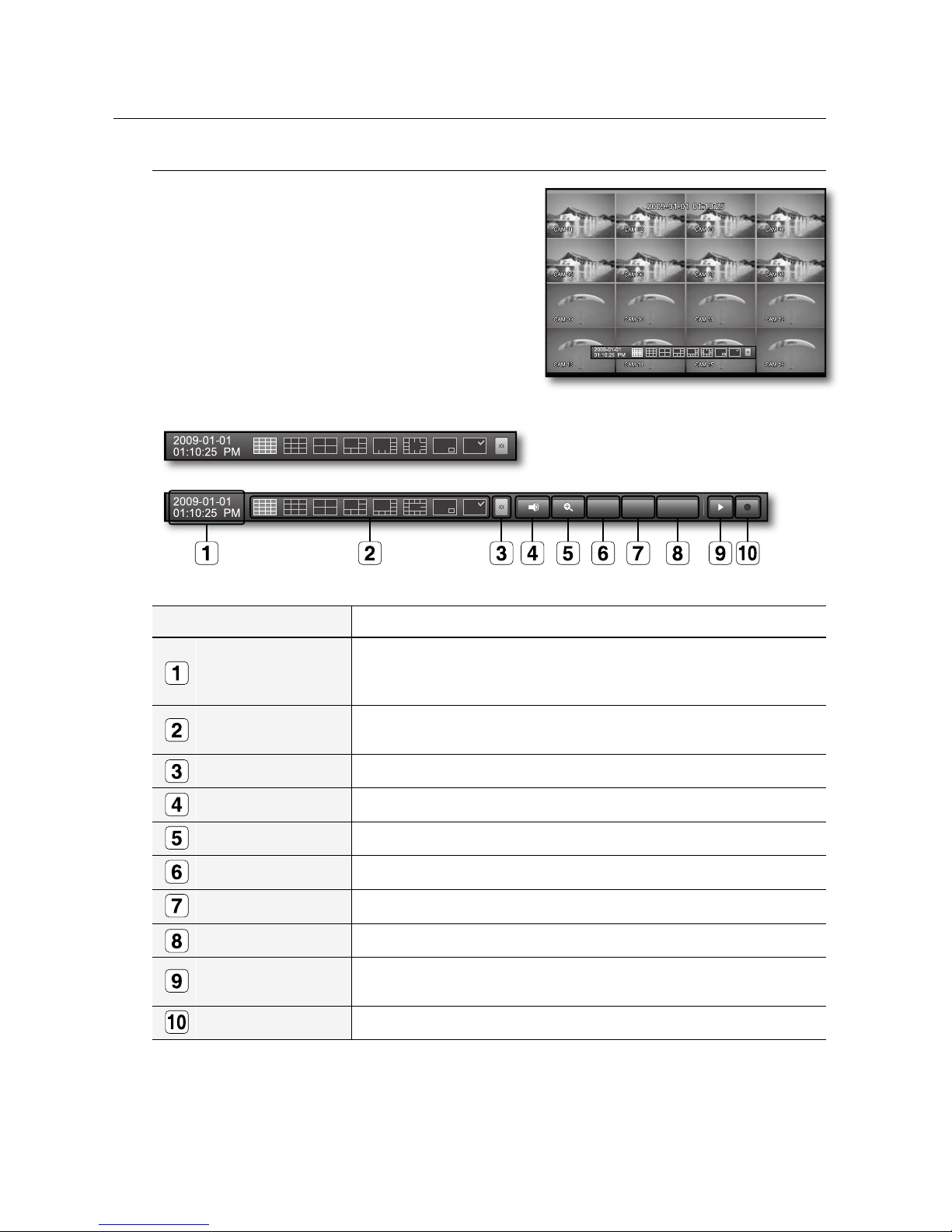
View the Launcher Menu
You can use the Launcher menu appearing on the bottom of
the live screen to access it.
In Live mode, right-click to display the context menu and
select <Show Launcher >.
Move the cursor to the bottom and click a desired item in
the Launcher menu.
If no input is entered for 10 seconds, the menu will disappear.
The Launcher menu can be accessed only using the mouse.
SHR-6080/6082 do not support the 16-split screen mode.
Menu Description
Date/Time
Displays the current time and date.
The indication of AM/PM is displayed if you set 12 hours for the time format in
“System>Date/Time/Language>Time”. (Page 34)
Screen Mode
Displays in the sequence of 16-, 9-, 4-, 6-, 8-, 13-split, PIP and Auto Sequence.
The current mode is highlighted in white.
Menu Expansion Button Click to display the hidden menu to the right.
Audio Turns ON/OFF the sound of the selected channel.
Zoom Enlarges the selected area. This is available only in Single Live mode.
PTZ Runs the PTZ Control launcher. This is available only in Single Live mode.
Alarm Stops the alarm if it's activated.
Freeze Freezes the Live screen temporarily.
Play Enters Play mode if a fi le to play exist, and if not, enters Search mode.
Record Start/End recording the Live screen.
1.
2.
M
PTZ
Alarm Freeze
English _29
LIVE
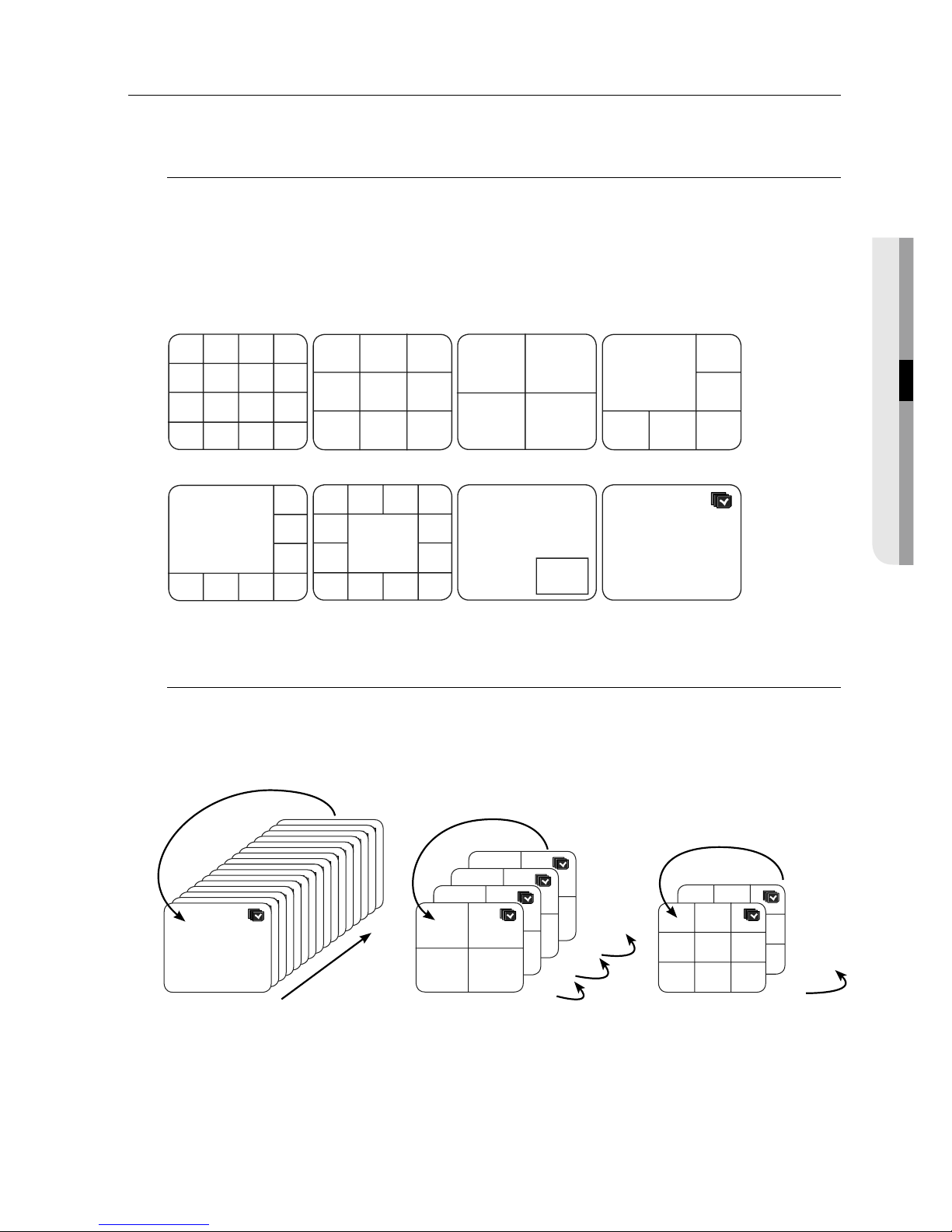
LIVE MODE
SHR-6160/6162/6163/6164 display Live images from 16 channels in a total of 8 layout of split screens.
Switching the screen mode
To switch the split mode, select a screen mode in the launcher menu, or right-click to select a screen mode in
the context menu.
Press the [MODE] button on the front panel or the remote control to switch the mode in the sequence of the
launcher menu items.
SHR-6080/6082 do not support the 16-split screen mode.
Switching the split mode
SHR-6160/6162/6163/6164 display 16 Live images in the sequence of Single, 4-split and 9-split modes.
Auto Sequence
In Single mode, If you have set <SEQ-Dwell Time> in “Setting the Device>Camera”, Auto Sequence will be
conducted at the set interval. (Page 42)
In a split mode, If you have set <Multi CH SEQ Time> in “Setting the Device>Monitor”, Auto Sequence will be
conducted at the set interval. (Page 47)
M
M
CH1
CH1
CH1
CH2
CH3
CH2
CH3 CH4
CH2 CH3
CH4 CH5 CH6
CH4 CH5 CH6
CH7 CH8 CH9
CH1 CH2 CH3 CH4
CH5 CH6 CH7 CH8
CH9 CH10 CH11 CH12
CH13 CH14 CH15 CH16
CH1
CH2
CH1
CH2
CH6
CH8
CH10 CH11 CH12 CH13
CH3 CH4 CH5
CH7
CH9
CH1
CH5 CH6 CH7 CH8
CH2
CH3
CH4
CH1
16-split mode 9-split mode 4-split mode 6-split mode
8-split mode 13-split mode PIP
Auto Sequence
16
CH1
CH1
CH1
CH1
CH1
CH1
CH1
CH1
CH1
CH1
CH1
CH1
CH1
CH1
CH1
CH1
1
Single mode
CH1 CH2
CH3 CH4
CH1 CH2
CH3 CH4
CH1 CH2
CH3 CH4
CH1 CH2
CH3 CH4
13-16
9-12
5-8
1-4
4-split mode
CH1 CH2 CH3
CH4 CH5 CH6
CH7 CH8 CH9
CH1 CH2 CH3
CH4 CH5 CH6
CH7 CH8 CH9
10-16
1-9
9-split mode
30_ live
live
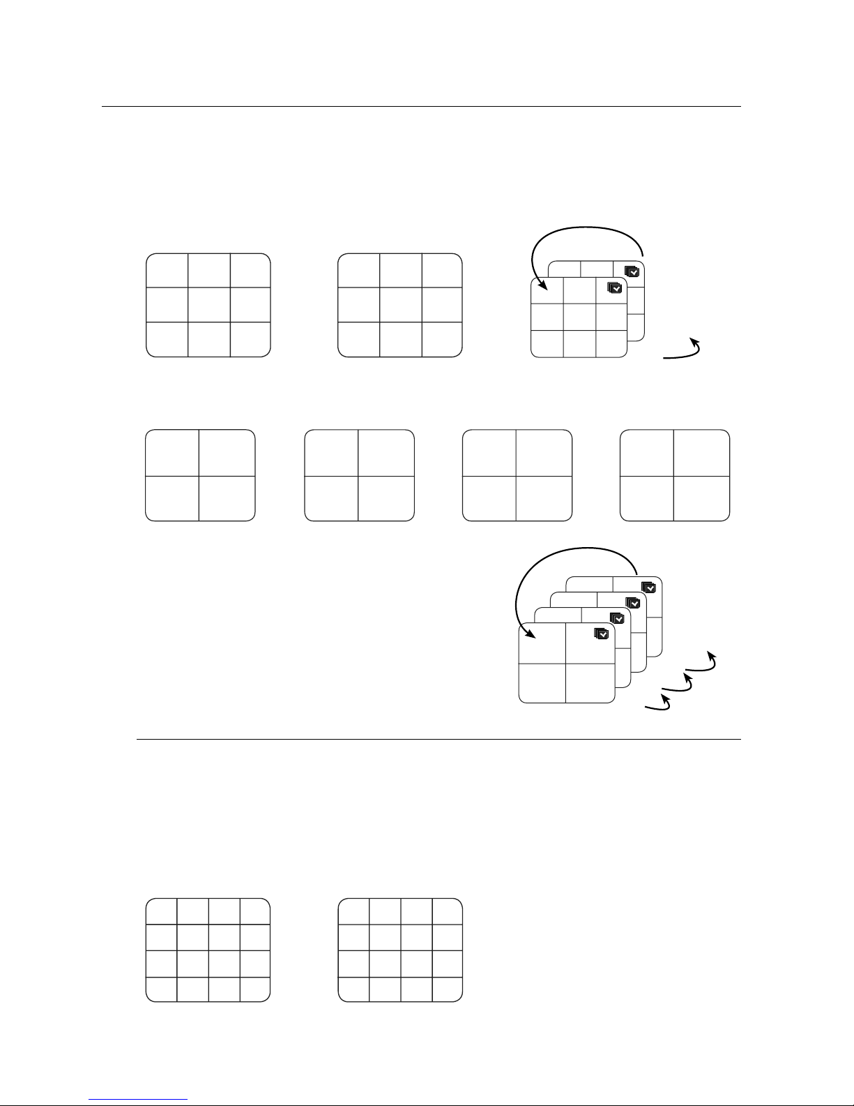
Manual Switching
Press the left/right button on the front panel or the remote control, or click the arrow <◄/►> key to move to
the next split mode.
If pressing the right [
►
] button in 9-split mode:
9-split (CH 1~9) mode 9-split (CH 10~16) mode Auto Sequence
If pressing the right [
►
] button in 4-split mode:
Channel (CH 1~4) Channel (CH 5~8) Channel (CH 9~12) Channel (CH 13~16) Auto Sequence
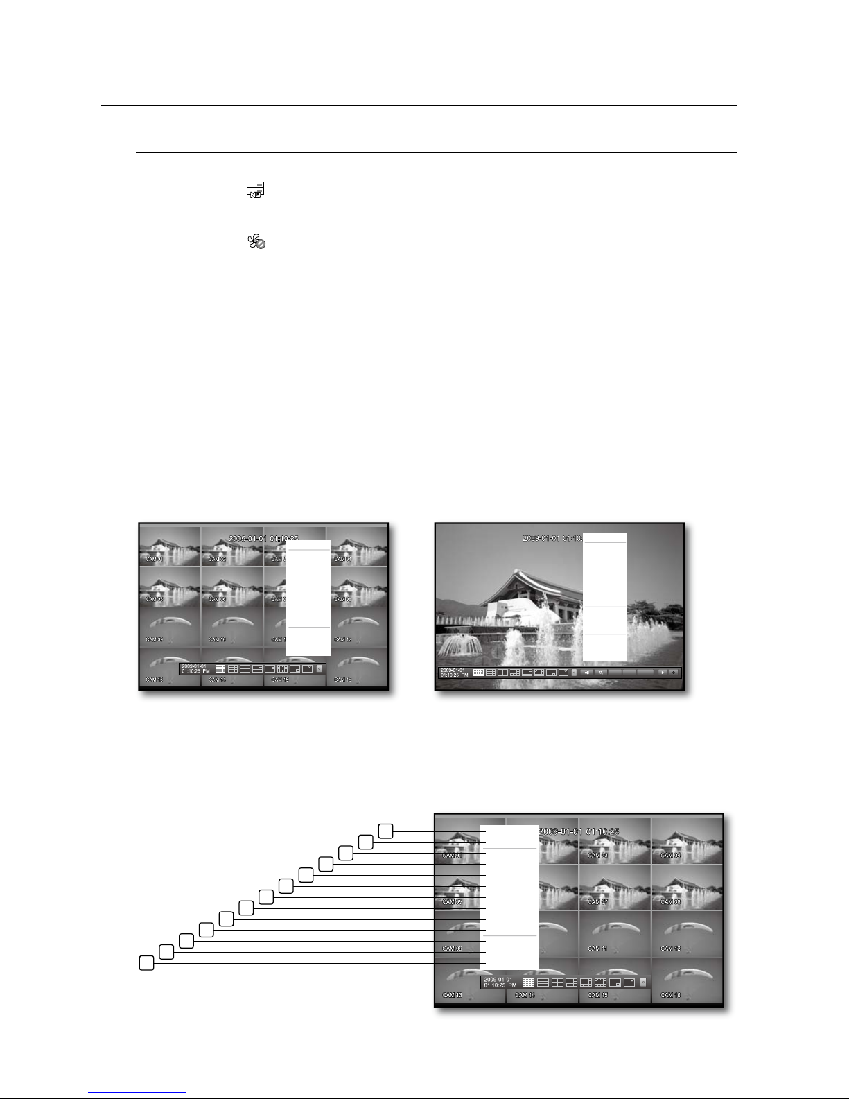
Channel Setting
You can display the channel in a desired area of a split screen.
Place the cursor over the camera name of each channel to display the <
▼
> key to the right on the screen.
Click a camera name to display a channel list where you can select a different channel.
Select a desired channel and click it.
The current channel will be switched to the selected one.
Ex : if switching CH 1 to CH 7
•
•
1.
2.
3.
CH1 CH2
CH3 CH4
CH5 CH6
CH7 CH8
CH9 CH10
CH11 CH12
CH13 CH14
CH15 CH16
CH1 CH2
CH3 CH4
CH1 CH2
CH3 CH4
CH1 CH2
CH3 CH4
CH1 CH2
CH3 CH4
13-16
9-12
5-8
1-4
CH1 CH2 CH3
CH4 CH5 CH6
CH7 CH8 CH9
CH10 CH11 CH12
CH13 CH14 CH15
CH16
CH1 CH2 CH3
CH4 CH5 CH6
CH7 CH8 CH9
CH1 CH2 CH3
CH4 CH5 CH6
CH7 CH8 CH9
10-16
1-9
CH1 CH2 CH3 CH4
CH5 CH6 CH7 CH8
CH9 CH10 CH11 CH12
CH13 CH14 CH15 CH16
CH7 CH2 CH3 CH4
CH5 CH6 CH1 CH8
CH9 CH10 CH11 CH12
CH13 CH14 CH15 CH16
 Loading...