


3-1
Samsung Electronics
3. Disassembly and Reassembly
3.1 General Precautions on Disassembly
>> Caution about the Graphic Print Bar
When you disassemble and reassemble components, you must use extreme caution. The close proximity of cables to
moving parts makes proper routing a must.
If components are removed, any cables disturbed by the procedure must be restored as close as possible to their original positions. Before removing any component from the machine, note the cable routing that will be affected.
Whenever servicing the machine, you must perform as follows:
1. Check to verify that documents are not stored in memory.
2. Be sure to remove the toner cartridge before you disassemble parts.
3. Unplug the power cord.
4. Use a flat and clean surface.
5. Replace only with authorized components.
6. Do not force plastic-material components.
7. Make sure all components are in their proper position.
>> Releasing Plastic Latches
Many of the parts are held in place with plastic latches. The latches break easily;
release them carefully.
To remove such parts, press the hook end of the latch away from the part to
which it is latched.
The Graphic Print Bar is a part supplied from other company, and the whole parts are treated as one material. Therefore,
replace the whole Graphic Print Bar when replacement is necessary. The below information is cautions about the Graphic
Print Bar when replacing it or handling it.
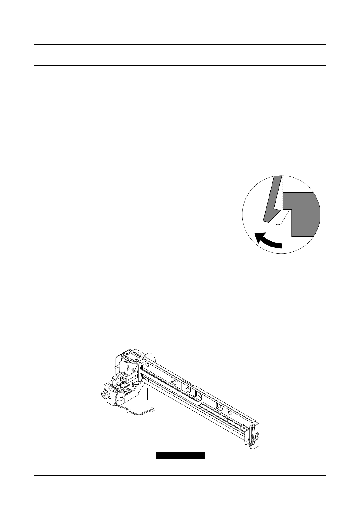
The Figure A in the below shows parts of the Graphic Print Bar.
SS(Service Station) Motor
Rotating Serive Assembly
Carriage Assembly
Carriage Motor
Figure A

Disassembly and Reassembly
3-2
Samsung Electronics
1. Do not move the Carriage Assembly from the Service
Station by force. The Carriage Assembly must be
mounted to the Service Station all the time except
when it is printing, or ink cartridge is being replaced.
When the Carriage Assembly is mounted, it is being
caught by latch. If it is moved by force, the latch part
could be broken and malfunctioned. For moving the
Carriage Assembly, turn the gear located under the
Service Station. (See Figure B)
2. Locate the Rotating Service Assembly on the exact
point. The Rotating Service Assembly consists of two
wipers and two nozzle caps (Mono or Color). Locate
the nozzle cap (Mono or Color), adequate to the
mounted ink cartridge, on the top. (See Figure C)
If the Rotating Service Assembly is slightly inclined, the
Carriage cannot return to the Service Station, and the
machine acknowledges it as an error (paper jam).
Therefore, locate the Rotating Service Assembly on the
exact point as shown as picture B, and turn the power
OFF/ON when paper jam is occurred.
3. Need special attention when assemble the Graphic
Print Bar on the Engine unit.The two points must be
assembled perfectly as shown as picture D when
assemble the Graphic Print Bar.If not, the interval
between paper and ink nozzle is wider in printing
process. As a result, a bad image will be caused.
<The location of Nozzle Cap when Mono Ink Cartridge is mounted >
<The location of Nozzle Cap when Ink Cartridge is mounted>
<Shape of inclined nozzle cap>
Figure B
1
2
Figure D
When the nozzle cap is
inclined
Locate the nozzle cap
forward to the top.
Locate the nozzle cap
forward to the top.
Figure C
Rotate Gear to
Release Carriage Lock
Disassembly and Reassembly
3-3
Samsung Electronics
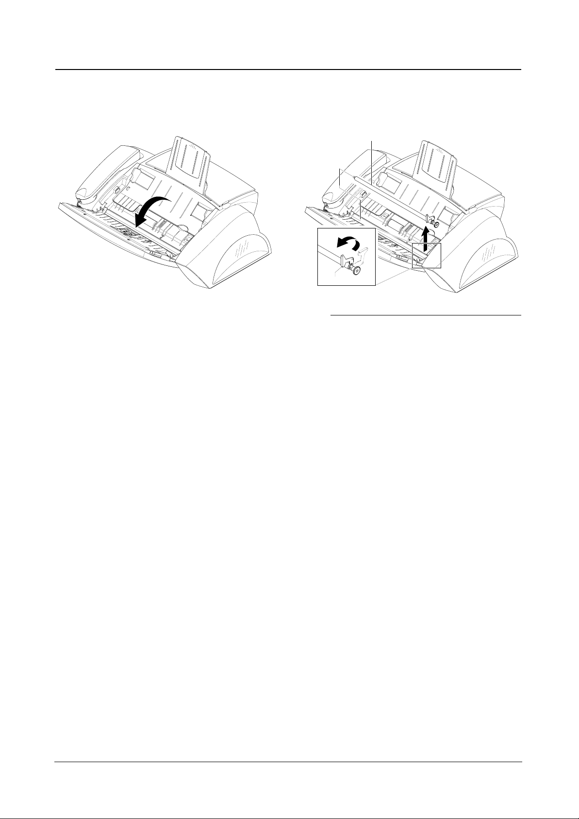
3.2 White Roller
1. Open the OPE Unit, as shown below. 2. Pull the White Roller Bushing, then rotate it until it
reaches the slot, as shown below. Then lift the White
Roller out.
White Roller
Bushing
Note : Check the Roller for any dirt. If dirty, wipe it off with soft cloth
dampened with water. If the Roller is heavily worn, replace it
with a new one.

Disassembly and Reassembly
3-4
Samsung Electronics
3.3 Top Cover
1. Before you remove the Top Cover, you should remove
• White Roller (see page 3-3)
2. Remove the Handset and Chute.
3. Unlatch the Guide Extension securing the ASF Unit,
as shown below.
Then lift the Guide Extension out.
4. Remove the six screws securing the Top Cover.
5. Remove the Top Cover, make sure it is properly
hooked.
Chute
Handset
Top Cover
Hook
Guide Extension

Disassembly and Reassembly
3-5
Samsung Electronics
3.4 ADF Rubber Pad
1. Open the OPE Unit. 2. Insert a flat blade screw driver into the slot as shown
below, and remove the Rubber Holder and the
Rubber Pad.
Note1 : When reassembling the Rubber Pad, be sure that it and the
Holder fit into the guide boss and the Holder latches fit into
the corresponding hole.
Note2 : Clean the surface of the Rubber Pad with ethylalcohol. After
wiping, be sure to dry it. Check for rubber wear. If the wear
reaches 1/2 its original thickness, replace it with a new one.
Rubber Holder
ADF Rubber
3.5 LIU Board
1. Before you remove the LIU Board, you should remove
• White Roller (see page 3-3)
• Top Cover (see page 3-4)
2. Unplug the all connectors from the LIU Board.
3. Remove the one screw securing the LIU Board and
remove it.
Main B'd
OPE B'd
CIS B'd
Sheet Insulation
CN1
CN2
CN3
Screw
LIU Board
CN1 Main B’d
CN2 OPE B’d
CN3 CIS B’d