

Samsung SCW230 Troubleshooting

■ Troubleshooting
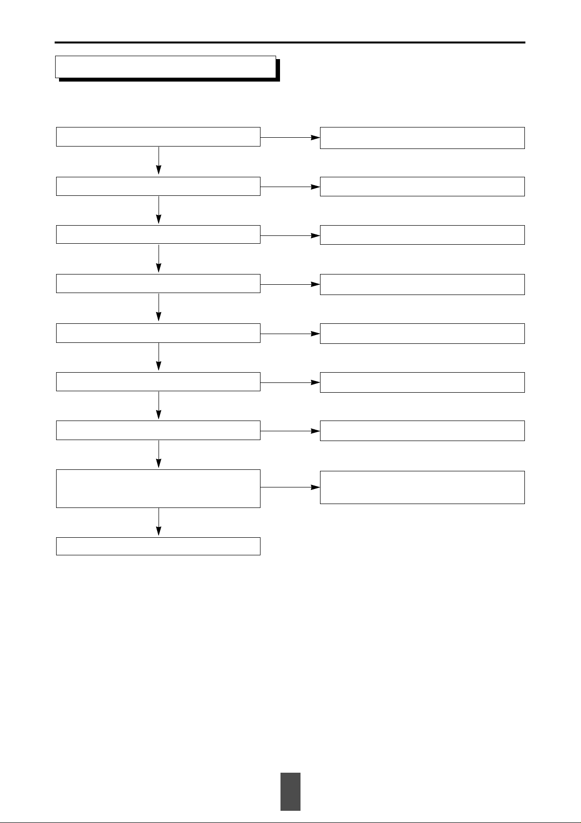
+5V, +12V is correctly supplied to
CN01 after power cable is plugged in?
X100, X200, X300, X600, X700
oscillate?
Check power fuse and power cable
connection.
After checking IC10, IC20, IC32, IC62, IC71 power
input, replace oscillator(X-TAL) if IC is not defective.
-8V correctly generated?
4V correctly generated?
Check IC22 related circuitry.
Y
Y
N
N
N
N
N
Y
Y
Check soldering of
IC10, IC62 and power
source. Replace IC if
defective.
N
Check Q700
related terminals.
IC71 PIN4 changes 0V→5V→0V
when power is supplied?
After IC71 PIN4 open, check if Q700 collector
terminal changes 0V→5V→0V.
Refer to ‘No SLED Operation’.
Refer to ‘No Tray Open/Close’.
Y
Y
N
Y
Y
Pick-Up moves in at power on after
moving out?
N
Tray Open/Close normal?
Refer to ‘No Laser Diode ON’
N
Laser diode ON?
Y
Refer to ‘No Focus Lock’.
N
Focus Up/Down normal?
Refer to ‘No Spindle Motor Rotation’.
N
Y
N
Focus Lock normal?
Y
Y
N
Spindle Lock normal?
Pause mode
Y
Disc rotates?
Check R317 related pattern short and
replace P/U Ass’y if not defective.
13
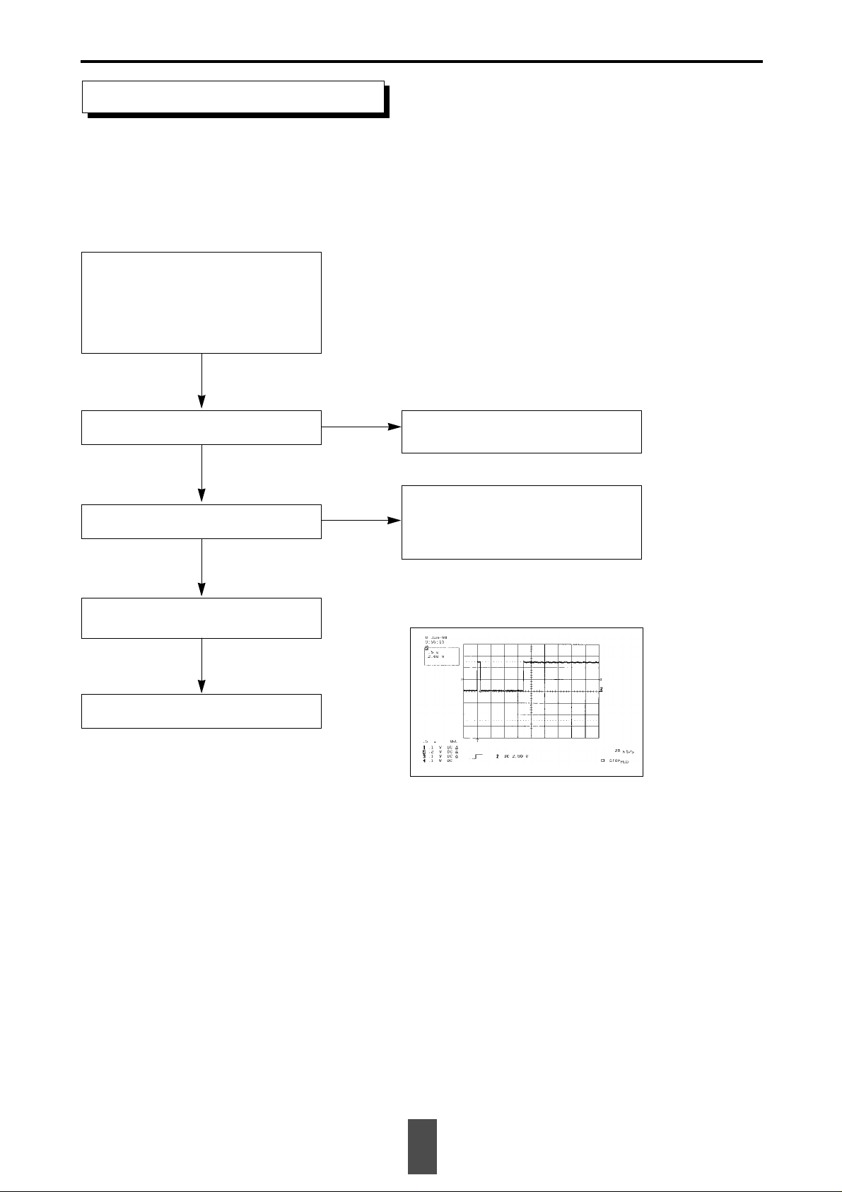
1. Verify the circuit of power unit and initial status
Fig. 1 Waveforms of IC22 PIN2 at normal operation
(-8V verified)
No Tray Open/Close
CN07 lead wires are correctly connected?
Check if problem persists after inserting or adjusting
lead wires to CN07.
N
Y
0V detected at IC71 PIN42 when pressed SW01?
When OPEN (CLOSE)
Check SW01 pattern and soldering.
N
Y
IC10 PIN32(33) changes 5V→0V?
Check IC10 PIN1,2,3,78 pattern and soldering.
N
Y
Q103(Q102) BASE changes 5V→2V?
Check R111,112(R120,119) and soldering.
N
Y
Q103(Q102) COLLECTOR changes 0V→2V?
Replace Q103(Q102).
N
Y
Q101(Q100) BASE changes 5V→4V?
Check R115,114(R122,121) soldering.
N
Y
Q101(Q100) COLLECTOR changes 0V→5V?
Replace MECHA.
Replace Q101(Q100).
N
Y
5V output power detected at -(+) terminal
of Tray Motor?
Check if CN07 is correctly inserted and soldering is in
good condition.
N
Y
14
No Laser Diode ON
Check R317 soldering and replace MECHA if
soldering is not the cause of the problem.
N
Check power supply to
Module PCB of MECHA.
CN02-PIN5 : 5V
PIN15 : 12V
CN03-PIN14,15 : 5V
PIN20 : -8V
You may have to lift CLAMPER upward in order to check Laser Diode ON/OFF condition. In that case, do NOT lift it upward more
than 1 inch as it may cause to deform the spring at the rear part of the clamper. When the spring got deformed, clamper can not be
placed in the right center of the DISC possibly resulting in annoying noise or vibration when the DISC is rotating.
Y
CN03 PIN18 : 4V?
Y
Check R215 soldering, IC20 PIN25,26,27 or
IC10 PIN22,42,43 sodering and check pattern
and operating status of IC20.
N
CN03 PIN16 changes 0V→5V?
Replace MECHA.
Y
CN03 FPC has no problem such
as loose or open connection?
Y
15
Fig 2. Waveforms of IC20 PIN2 at Power ON
(High Active)
 Loading...