

Samsung sct57b service manual
COLOR TELEVISION RECEIVER
Chassis : SCT57B
Model: CK569BGT1X/BWT
CK569BGT1X/VWT
COLOR TELEVISION RECEIVER CONTENTS
Precautions
Specifications and IC Data
Disassembly and Reassembly
Alignment and Adjustment
Troubleshooting
Exploded View and Parts List
Electric Parts List
Block Diagram
PCB Layout Diagram
Wiring Diagram
Schematic Diagrams
1.
2.
3.
4.
5.
6.
7.
8.
9.
10.
11.

ELECTRONICS
©
Samsung Electronics Co., Ltd. MAY.1998
Printed in Korea
3SCT57B-6908
1-1
Precautions
Samsung Electronics
1. Precautions
1. Be sure that all of the built-in protective
devices are replaced. Restore any missing
protective shields.
2. When reinstalling the chassis and its
assemblies, be sure to restore all protective
devices, including: nonmetallic control
knobs and compartment covers.
3. Make sure that there are no cabinet
openings through which people-particularly children--might insert fingers
and contact dangerous voltages. Such
openings include the spacing between the
picture tube and the cabinet mask,
excessively wide cabinet ventilation slots,
and improperly fitted back covers.
If the measured resistance is less than 1.0
megohm or greater than 5.2 megohms, an
abnormality exists that must be corrected
before the unit is returned to the customer.
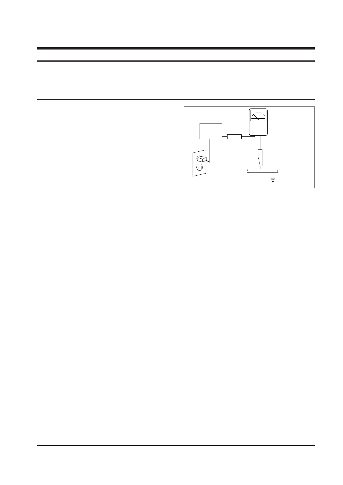
4. Leakage Current Hot Check (Figure 1-1):
Warning: Do not use an isolation
transformer during this test. Use a leakagecurrent tester or a metering system that
complies with American National Standards
Institute (ANSI C101.1, Leakage Current for
Appliances), and Underwriters Laboratories
(UL Publication UL1410, 59.7).
5. With the unit completely reassembled, plug
the AC line cord directly into the power
outlet. With the unit's AC switch first in the
ON position and then OFF, measure the
current between a known earth ground
(metal water pipe, conduit, etc.) and all
exposed metal parts, including: antennas,
handle brackets, metal cabinets, screwheads
and control shafts. The current measured
should not exceed 0.5 milliamp. Reverse the
power-plug prongs in the AC outlet and
repeat the test.
6. Antenna Cold Check:
With the unit's AC plug disconnected from
the AC source, connect an electrical jumper
across the two AC prongs. Connect one
lead of the ohmmeter to an AC prong.
Connect the other lead to the coaxial
connector.
7. X-ray Limits:
The picture tube is especially designed to
prohibit X-ray emissions. To ensure
continued X-ray protection, replace the
picture tube only with one that is the same
type as the original. Carefully reinstall the
picture tube shields and mounting
hardware; these also provide X-ray
protection.
8. High Voltage Limits:
High voltage must be measured each time
servicing is done on the B+, horizontal
deflection or high voltage circuits. Correct
operation of the X-ray protection circuits
must be reconfirmed whenever they are
serviced. (X-ray protection circuits also may
be called "horizontal disable" or "holddown".)
Heed the high voltage limits. These include
the XÐray Protection Specifications Label, and
the Product Safety and X-ray Warning Note on
the service data schematic.
LEAKAGE
CURRENT
TESTER
DEVICE
UNDER
TEST
TEST ALL
EXPOSED METAL
SURFACES
2-WIRE CORD
ALSO TEST WITH
PLUG REVERSED
(USING AC ADAPTER
PLUG AS REQUIRED)
EARTH
GROUND
(READING SHOULD
NOT BE ABOVE
0.5mA)
1-1 Safety Precautions
Fig. 1-1 AC Leakage Test
Follow these safety, servicing and ESD precautions to prevent damage and protect against potential
hazards such as electrical shock and X-rays.

Precautions
1-2
Samsung Electronics
1-1 Safety Precautions (Continued)
15. Observe the original lead dress,
especially near the following areas:
Antenna wiring, sharp edges, and
especially the AC and high voltage power
supplies. Always inspect for pinched,
out-of-place, or frayed wiring. Do not
change the spacing between components
and the printed circuit board. Check the
AC power cord for damage. Make sure
that leads and components do not touch
thermally hot parts.
16. Picture Tube Implosion Warning:
The picture tube in this receiver employs
"integral implosion" protection. To
ensure continued implosion protection,
make sure that the replacement picture
tube is the same as the original.
17. Do not remove, install or handle the
picture tube without first putting on
shatterproof goggles equipped with side
shields. Never handle the picture tube by
its neck. Some "in-line" picture tubes are
equipped with a permanently attached
deflection yoke; do not try to remove
such "permanently attached" yokes from
the picture tube.
18. Product Safety Notice:
Some electrical and mechanical parts
have special safety-related characteristics
which might not be obvious from visual
inspection. These safety features and the
protection they give might be lost if the
replacement component differs from the
original--even if the replacement is rated
for higher voltage, wattage, etc.
Components that are critical for safety are
indicated in the circuit diagram by
shading, ( ) or ( ).
Use replacement components that have
the same ratings, especially for flame
resistance and dielectric strength
specifications. A replacement part that
does not have the same safety
characteristics as the original might create
shock, fire or other hazards.
9. High voltage is maintained within specified
limits by close-tolerance, safety-related
components and adjustments. If the high
voltage exceeds the specified limits, check
each of the special components.
10. Design Alteration Warning:
Never alter or add to the mechanical or
electrical design of this unit. Example: Do
not add auxiliary audio or video
connectors. Such alterations might create
a safety hazard. Also, any design changes
or additions will void the manufacturer's
warranty.
11. Hot Chassis Warning:
Some TV receiver chassis are electrically
connected directly to one conductor of the
AC power cord. If an isolation transformer
is not used, these units may be safely
serviced only if the AC power plug is
inserted so that the chassis is connected to
the ground side of the AC source.
To confirm that the AC power plug is
inserted correctly, do the following: Using
an AC voltmeter, measure the voltage
between the chassis and a known earth
ground. If the reading is greater than 1.0V,
remove the AC power plug, reverse its
polarity and reinsert. Re-measure the
voltage between the chassis and ground.
12. Some TV chassis are designed to operate
with 85 volts AC between chassis and
ground, regardless of the AC plug polarity.
These units can be safely serviced only if
an isolation transformer inserted between
the receiver and the power source.
13. Some TV chassis have a secondary
ground system in addition to the main
chassis ground. This secondary ground
system is not isolated from the AC power
line. The two ground systems are
electrically separated by insulating
material that must not be defeated or
altered.
14. Components, parts and wiring that
appear to have overheated or that are
otherwise damaged should be replaced
with parts that meet the original
specifications. Always determine the
cause of damage or overheating, and
correct any potential hazards.
!

1-3
Precautions
Samsung Electronics
5. Check the insulation between the blades of
the AC plug and accessible conductive parts
(examples: metal panels, input terminals
and earphone jacks).
6. Insulation Checking Procedure: Disconnect
the power cord from the AC source and
turn the power switch ON. Connect an
insulation resistance meter (500V) to the
blades of the AC plug.
The insulation resistance between each
blade of the AC plug and accessible
conductive parts (see above) should be
greater than 1 megohm.
7. Never defeat any of the B+ voltage
interlocks. Do not apply AC power to the
unit (or any of its assemblies) unless all
solid-state heat sinks are correctly installed.
8. Always connect a test instrument's ground
lead to the instrument chassis ground
before connecting the positive lead; always
remove the instrument's ground lead last.
1-3 Precautions for Electrostatically Sensitive Devices (ESDs)
1. Some semiconductor ("solid state") devices
are easily damaged by static electricity.
Such components are called Electrostatically
Sensitive Devices (ESDs); examples include
integrated circuits and some field-effect
transistors. The following techniques will
reduce the occurrence of component
damage caused by static electricity.
2. Immediately before handling any
semiconductor components or assemblies,
drain the electrostatic charge from your
body by touching a known earth ground.
Alternatively, wear a discharging
wrist-strap device. (Be sure to remove it
prior to applying power--this is an electric
shock precaution.)
3. After removing an ESD-equipped assembly,
place it on a conductive surface such as
aluminum foil to prevent accumulation of
electrostatic charge.
4. Do not use freon-propelled chemicals.
These can generate electrical charges that
damage ESDs.
5. Use only a grounded-tip soldering iron
when soldering or unsoldering ESDs.
6. Use only an anti-static solder removal
device. Many solder removal devices are
not rated as "anti-static"; these can
accumulate sufficient electrical charge to
damage ESDs.
7. Do not remove a replacement ESD from its
protective package until you are ready to
install it. Most replacement ESDs are
packaged with leads that are electrically
shorted together by conductive foam,
aluminum foil or other conductive
materials.
8. Immediately before removing the protective
material from the leads of a replacement
ESD, touch the protective material to the
chassis or circuit assembly into which the
device will be installed.
9. Minimize body motions when handling
unpackaged replacement ESDs. Motions
such as brushing clothes together, or lifting
a foot from a carpeted floor can generate
enough static electricity to damage an ESD.
WARNING1: First read the "Safety Precautions" section of this manual. If some unforeseen circumstance creates a conflict
between the servicing and safety precautions, always follow the safety precautions.
WARNING2: An electrolytic capacitor installed with the wrong polarity might explode.
1-2 Servicing Precautions
1. Servicing precautions are printed on the
cabinet. Follow them.
2. Always unplug the unit's AC power cord
from the AC power source before
attempting to: (a) Remove or reinstall any
component or assembly, (b) Disconnect an
electrical plug or connector, (c) Connect a
test component in parallel with an
electrolytic capacitor.
3. Some components are raised above the
printed circuit board for safety. An
insulation tube or tape is sometimes used.
The internal wiring is sometimes clamped to
prevent contact with thermally hot
components. Reinstall all such elements to
their original position.
4. After servicing, always check that the
screws, components and wiring have been
correctly reinstalled. Make sure that the
portion around the serviced part has not
been damaged.
2-1
Specifications and IC Data
Samsung Electronics
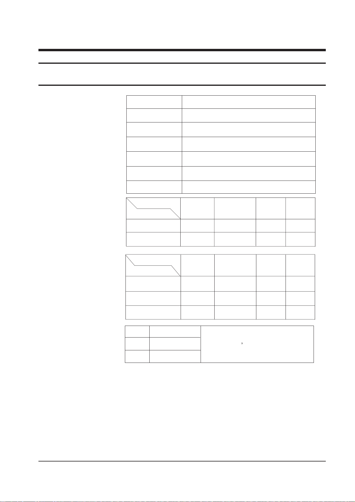
2. Specifications and IC Data
Television System:
Channels:
Intermediate Frequencies (MHz) :
Picture Tube:
Power Requirements:
Antenna Input Impedance:
Speaker Impedance
NTSC - M
2 - 13
14-69
NTSC - M
38.90
34.40
35.32
PAL/SECAM-
B/G,I
2 - 12
21 - 69
PAL/
SECAM- B/G
38.90
33.40
34.47
System
Band
VHF
UHF
SYSTEM
IF Carrier Frequency
Picture IF Carrier
Sound IF Carrier
Color Sub Carrier
PAL,
SECAM- D/K
1 - 13
21 - 69
PAL/SECAM-D/K,
SECAM-K1
38.90
32.40
34.47
SECAM-K1,
PAL-D
2 - 9
13 - 57
PAL - I
38.90
32.90
34.47
MODEL
CI
CII
CX
CK
CW
CS
14 Inch
20 Inch
22 Inch
AC 100 ~ 260V, 50/60Hz or AC 160 ~ 260V, 50/60Hz
VHF, UHF : Telescopic dipole antenna (75 ohm unbalanced type )
10W + 10W/8 ohm, 3W/16 ohm, 5W + 5W/16 ohm
SYSTEM
PAL-I (UHF)
PAL-I (VHF/UHF)
PAL-B/G, SECAM-B/G
PAL-B/G, D/K, SECAM-B/G, D/K
PAL-B/G, D/K, SECAM-B/G, D/K, NT 4.43
PAL-B/G, D/K, SECAM-B/G, D/K, NT4.43, NT3.58
2-1 Specifications
A34KQV42X
A48KRD82X
A53QCA891X
Quick start, in-line-gun,
Black stripe, 90 degree deflection
Specifications and IC Data
2-2
Samsung Electronics
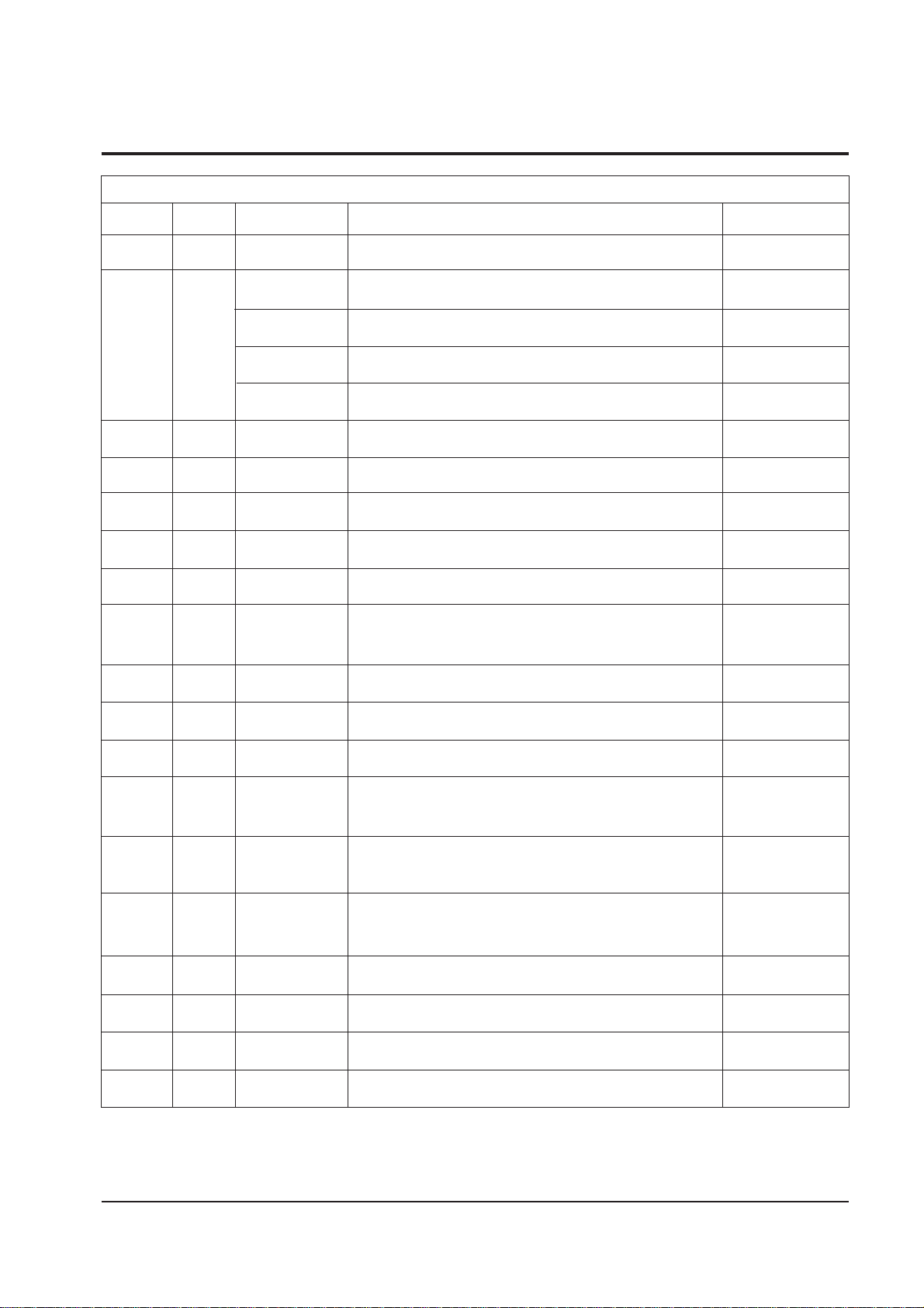
2-2 IC Line Up
No.
1
2
3
4
5
6
7
8
9
10
11
12
13
14
15
16
17
18
Description
IF PRE-AMP
PAL-B/G, SECAM-B/G,NTSC, SECAM-L
PAL-B/G, SECAM-B/G, SECAM-L
PAL-B/G, SECAM-B/G, NTSC, SECAM-L, E/W ADJ.
PAL-B/G, SECAM-B/G, NTSC, SECAM-L, E/W ADJ.,16:9
VERTICAL DEFLECTION AMP
REGULATOR (12V)
RGB DRIVE AMP
SOUND-AMP (10W+10W)
AUDIO PROCESSOR
POWER IC 6A, 800V
POWER IC 8A, 800V
PHOTO COUPLER
REGULATOR IC
REGULATOR (5V, 8V)
TTX-DECODER
µ-com
E2-PROM
SOUND PROCESSOR
INTER-CARRIER SOUND DEMODULATOR
NICAM+A2 SOUND DEMODULATOR
Y.U.V TRANSIENT IMPROVEMENT PROCESSOR
Remarks
RUSSIAN
SOUND MODULE
SOUND MODULE
SOUND MODULE
Specification
PAP102T
TDA8844
TDA8843
TDA8375A
TDA8375
TDA8350Q
KA7812
TDA6107Q
TDA7297
TDA9859
KA3S0680
KA3S0880
LTV817B
KA78R05
KA7630
SAA5281 P/E
SAA5281 P/H
SZM-199EA
SZM-199ER
AT24C04
AT24C08
TDA9840
TDA9820
TDA9874H
TDA9177
Loc No.
HIC101
IC202
IC301
IC401
IC501
IC601
IC701
IC801
IC802
IC803
IC804
ICT01
IC901
IC902
ICA01
ICA02
IC6001
ICL101
Table 2-1 IC Line Up
2-3
Specifications and IC Data
Samsung Electronics
Description
ENG/ARAB/FRENCH
ENG/CHINESE
ENG/CRO/BUL/POLISH/RUMANIAN/CZECH/CRO
ENG/GER/FRENCH/SPANISH/SWEDISH/DUTCH/ITALIAN
ENG/MAL/IND/VIETNAMESE/THAI
ENG/RUSSIAN
RemarksSpecification
SZM-199EA
SZM-199EC
SZM-199EW
SZM-199EE
SZM-199ET
SZM-199ER
Loc No.
IC901
Table 2-2
Option: OSD Language
Specifications and IC Data
2-4
Samsung Electronics
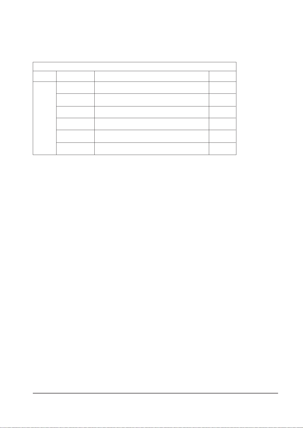
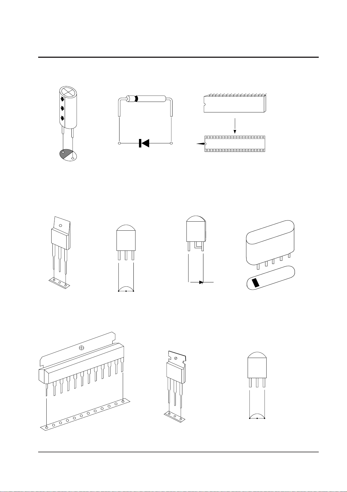
Fig.2-1 Semiconductor Base Diagrams
2-3 Semiconductor Base Diagrams
ELECTROLYTICCONDENSER
IC
DIODE
TDA4665(Pin 16)
TDA837X(Pin 56)
Z8933112PSC(Pin 42)
X24CO4P(Pin 8)
TDA8395(Pin 16)
TDA4665(Pin 16)
IC
TRANSISTOR TRANSISTOR
TDA8133
KA7812
IN
G
OUT
TRANSISTOR
TRANSISTOR
2SD1651
2SD1650
KSD5072
KSD5071
KSD1711
B
C
E
E B C
KSA815-Y
KSA539-Y
IC
UPC574J
or
KA33V
G1962
K2950M
K9253M
SAW-FILTER
1
E C B
KSR1012
KSR1010
KSR2010
3-1
Disassembly and reassembly
Samsung Electronics
3. Disassembly and Reassembly
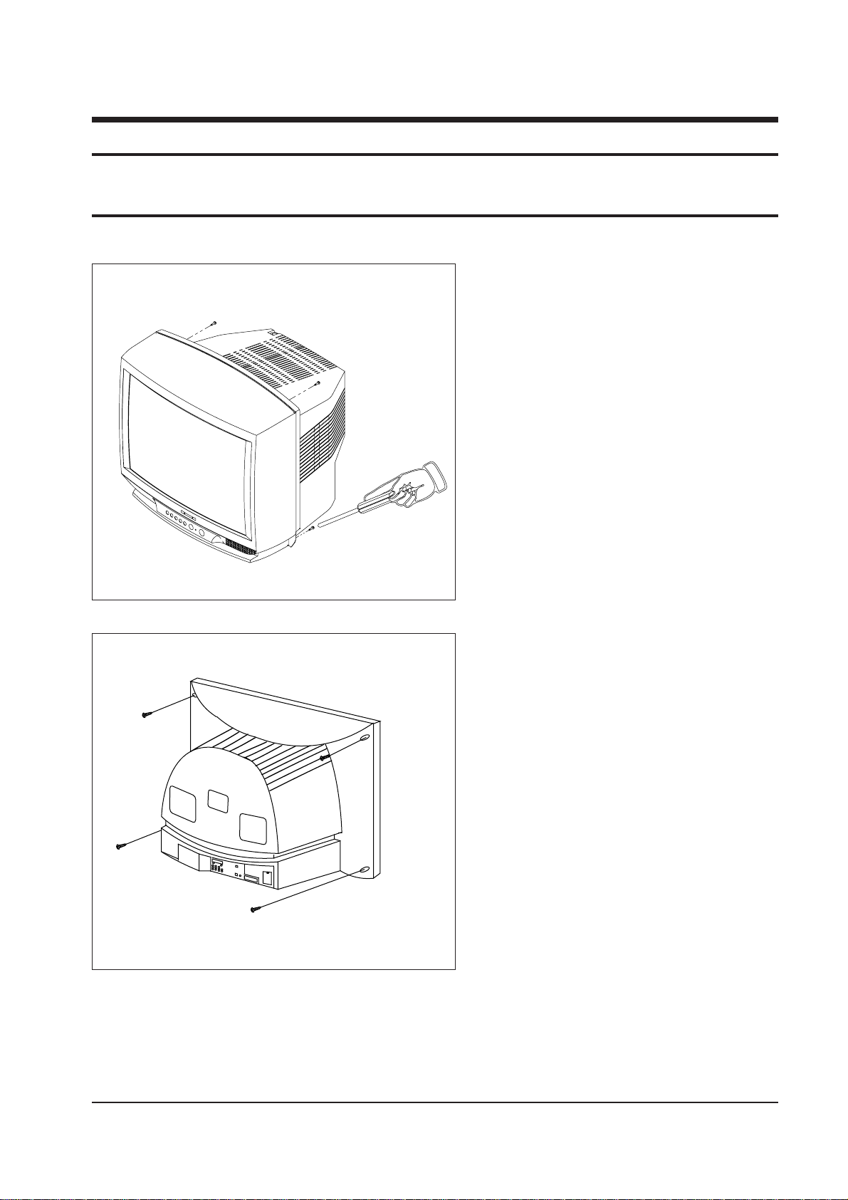
3-1 Back Cover Removal
1. After removing the 9 screws, pull the
cabinet backwards.
Disassembly and reassembly
3-2 Samsung Electronics
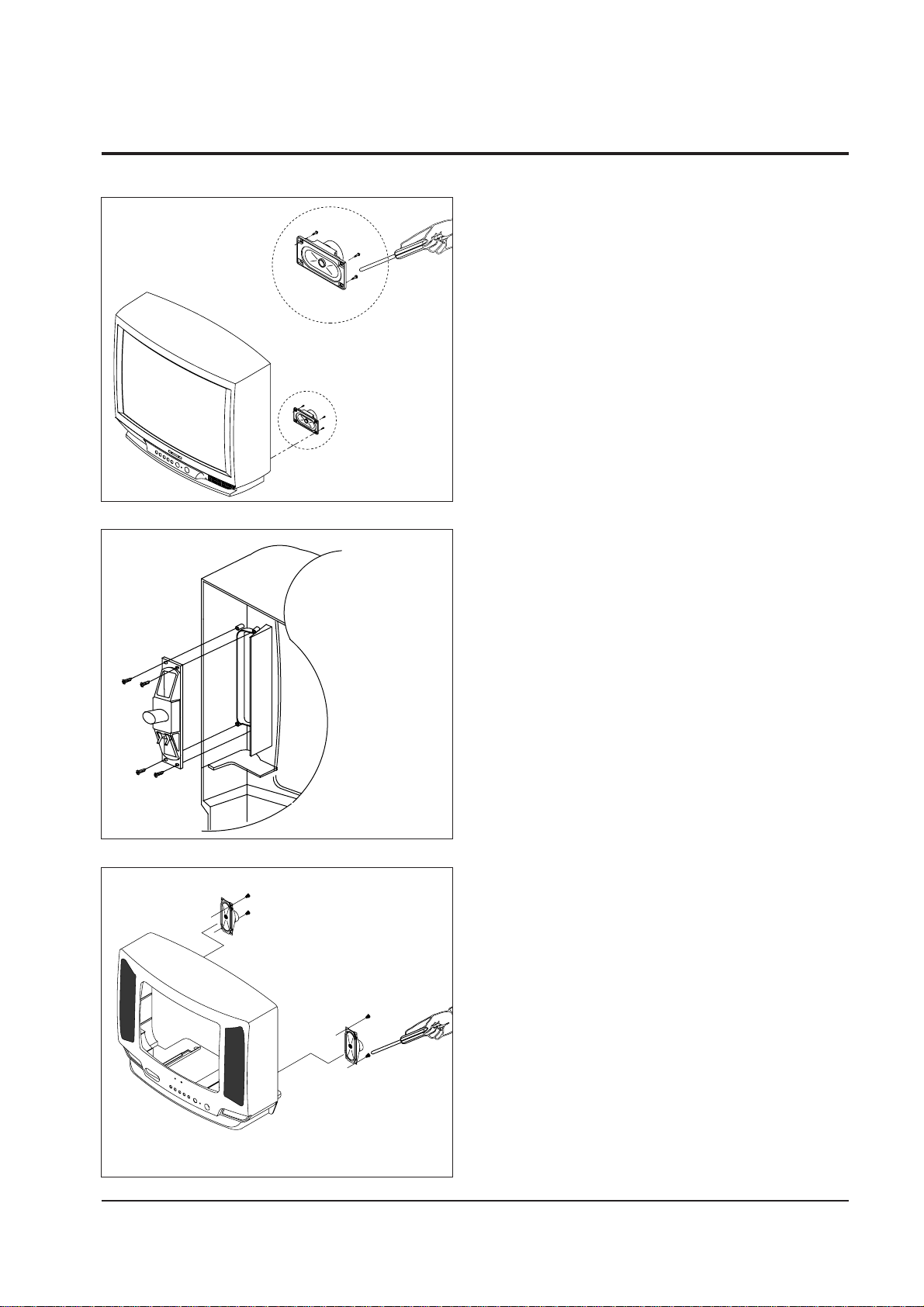
3-2 Speaker Removal
1. Loosen the 4 screws and remove the holder speakers.
3-3
Disassembly and reassembly
Samsung Electronics
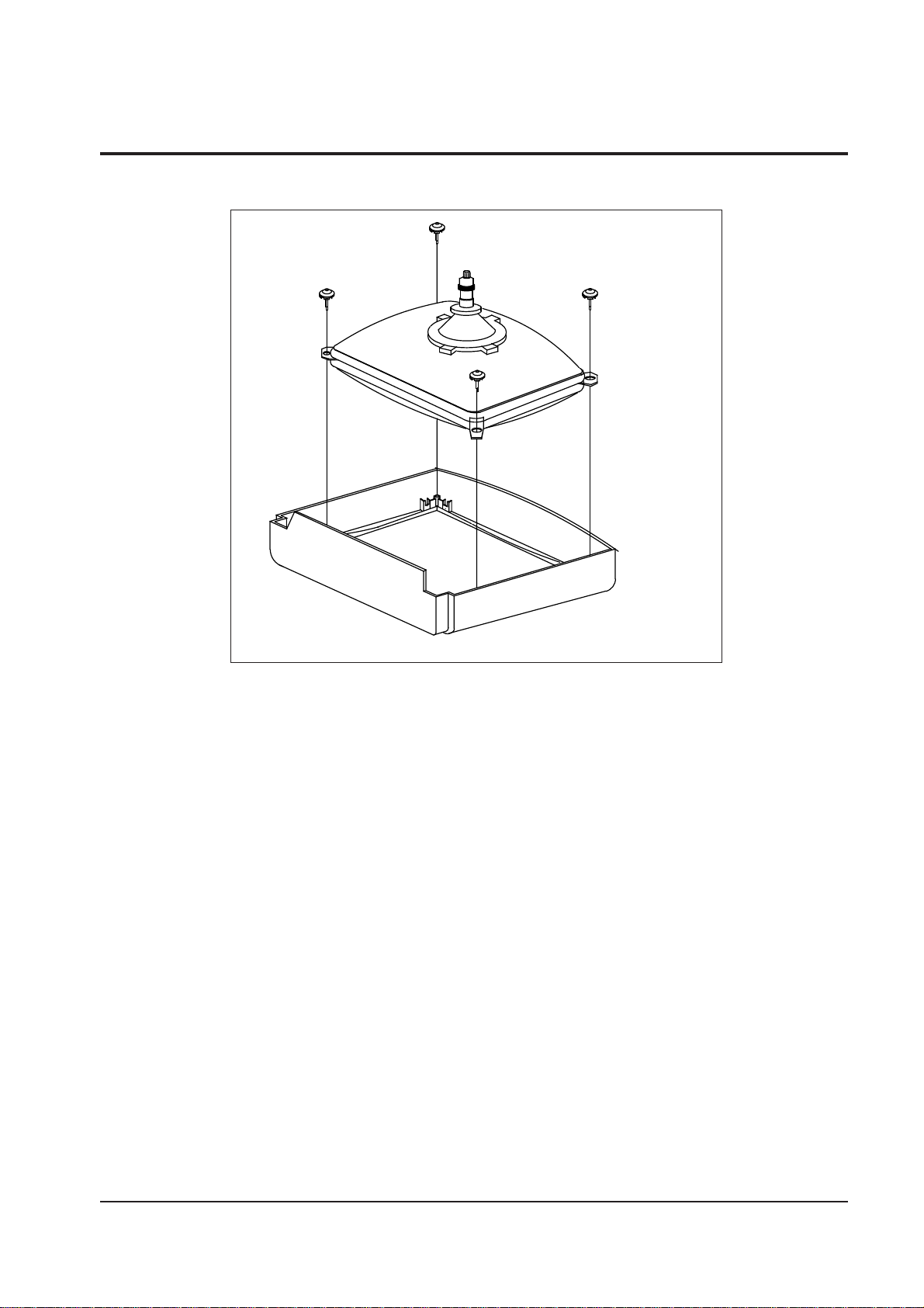
3-3 CRT Removal
1. Spread a soft mat on the floor. Place the TV set face down.
2. Remove the 4 screws mounting the CRT to the front cabinet.
3. Lift the CRT.

3-4 Samsung Electronics
MEMO
MEMO

4-1
Alignment and Adjustments
Samsung Electronics
4. Alignment and Adjustments
4-1 Preadjustment
4-1-1 Factory Mode
1. Do not attempt these adjustments in the Video
Mode.
2. The Factory Mode adjustments are necessary
when either the EEPROM (IC902) or the CRT is
replaced.
3. Do not tamper with the "Adjustment" screen of
the Factory Mode menu. This screen is
intended only for factory use.
4-1-2 When EEPROM (IC902) Is Replaced
1. When IC902 is replaced all adjustment data
revert to initial values. It is necessary to reprogram this data.
2. After IC902 is replaced, warm up the TV for 10
seconds
4-1-3 When CRT Is Replaced
1. Make the following adjustments AFTER
setting up after setting up purity and
convergence:
White Balance
Sub-Brightness
Vertical Center
Vertical Size
Horizontal Size
Fail Safe (This adjustment must be the last
step.)
2. If the EEPROM or CRT is replaced, set PSL
and PVA to 15 and 63 (Factory Mode).
4-2 Factory/Service Mode
4-2-1 Procedure for the "Adjustment" Mode
1. This mode uses the standard remote control.
The Service Mode is activated (1) by pressing
the (Display → (FACTORY) service key or (2)
by entering the following remote-control
sequence:
STAND-BY→DISPLAY→ P-STD → MUTE →
POWER ON
2. The "SERVICE (FACTORY)" message will be
displayed. The Service Mode has four
components: Adjustment, Test Pattern, Option
Bytes and Reset.
3. Access the Adjustment Mode by pressing the
"VOLUME" keys ( Up or Down). The
adjustment parameters are listed in the
accompanying table. Select them by pressing
the CHANNEL keys (▲,▼).
4. Selection sequences for the PAL system:
DOWN or UP key:
VCO>SBT>SCT>SCR>SC>RG>CDL>STT>LCO
>LA>PSL>PVS>PVA>PHS>PEW>PEP>PEC>P
ET>LSC>TSC>SA>NSL>NVS>NVA>NHS>NE
W>NEP>NEC>NET
5. Selection sequences for the NTSC system:
DOWN or UP key:
NVS>NVA>NSL>NHS>NEW>NEP>NEC>NET
6. The VOLUME keys increase or decrease the
adjustment values, (stored in the
non-volatile memory when Adjustment Mode
is cancelled).
7. Cancel the Adjustment Mode by re-pressing the
"Factory" or "Power on" keys.
Alignment and Adjustments
4-2 Samsung Electronics
ADJUSTMENT DATA
15
60 ~ 75
6 ~ 10
7
15 FIXED
11 FIXED
25 ~ 45
25 ~ 45
-
0 ~ 10
63 FIXED
5
20 ~ 25
25 ~ 35
35
35 ~ 45
35 ~ 45
0 ~ 10
15 ~ 30
15 ~30
31 FIXED
10 ~ 30
25
25 FIXED
RANGE
0 ~ 63 STEP
0 ~ 127 STEP
0 ~ 23 STEP
0 ~ 23 STEP
0 ~ 23 STEP
0 ~ 63 STEP
0 ~ 7 STEP
0 ~ 127 STEP
0 ~ 9 STEP
0 ~ 63 STEP
0 ~ 63 STEP
0 ~ 63 STEP
0 ~ 63 STEP
0 ~ 63 STEP
0 ~ 63 STEP
0 ~ 63 STEP
0 ~ 63 STEP
0 ~ 63 STEP
0 ~ 63 STEP
0 ~ 63 STEP
0 ~ 63 STEP
0 ~ 63 STEP
0 ~ 49 STEP
0 ~ 63 STEP
INITIAL
15
63
7
7
15
11
31
31
4
5
63
5
25
31
31
40
38
22
22
30
25
15
25
25
OSD ABBREVIATION
AGC
VCO
SBT
SCT
SCR
SC
RG
BG
CDL
STT
LCO
LA
PSL
PVS
PVA
PHS
PEW
PEP
PEC
PET
VSC
TSC
SA
NSL
FUNCTION
AUTO GAIN CONTROL
VOLTAGE CONTROLLED OSCILLATOR
SUB BRIGHT
SUB CONTRAST
SUB COLOR
S-CORRECTION
RED DRIVE (GAIN)
BLUE DRIVE (GAIN)
CATHODE DRIVE LEVEL
SUB TINT
SECAM-L CONTROLLED OSCILLATOR
SOUND LEVEL ADJUSTMENT
PAL VERTICAL SLOPE
PAL VERTICAL SHIFT
PAL VERTICAL AMPLITUDE
PAL HORIZONTAL SHIFT
PAL EW-WIDTH
PAL EW-PARABOLA
PAL EW CORNER PARABOLA
PAL EW-TRAPEZIUM
VERTICAL SCROLL
TTX SUB CONTRAST
SEPARATION ADJUSTMENT
NTSC VERTICAL SLOPE
Table 4-1 Main Adjustment Parameter (Zilog µ-com)
4-2-2 Main Adjustment Parameter
4-3
Alignment and Adjustments
Samsung Electronics
NOTE : PVS,PVA, PHS, NVS, NVA,NHS parameters must be aligned using both the
50Hz and 60Hz vertical-field rates.
4-2-3 Test Pattern
1. This mode can be used during servicing, or for confirming that
the convergence and purity adjustments are correct.
2. Access the Test Pattern parameters by pressing a CHANNEL
keys (▲,▼) while the Service Mode is on. The cursor will move
to the test pattern. Press the VOLUME keys. On-screen display:
■ RED
■ GREEN
■ BLUE
3. AGING Mode (Reference Only)
This pattern is used for pre-heating the CRT during
manufacturing--it is accessed in the factory by twice pressing the
"HIDDEN" key .
Even if the TV power is cut off, the Aging Mode is not cancelled,
The patterns are displayed at 5 sec intervals. The AGING mode
is cancelled by repressing the "HIDDEN" key.
ADJUSTMENT DATARANGE INITIALOSD ABBREVIATIONFUNCTION
35 ~ 45
25 ~ 35
35 ~ 50
35 ~ 45
15 ~ 30
0 ~ 63 STEP
0 ~ 63 STEP
0 ~ 63 STEP
0 ~ 127 STEP
0 ~ 63 STEP
44
28
45
37
21
20
30
NVS
NVA
NHS
NEW
NEP
NEC
NET
NTSC VERTICAL SHIFT
NTSC VERTICAL AMPLITUDE
NTSC HORIZONTAL SHIFT
NTSC EW-WIDTH
NTSC EW PARABOLA
NTSC EW-CORNER PARABOLA
NTSC EW-TRAPEZIUM
Table 4-1 Main Adjustment Parameter (Zilog µ-com)(Continued)
 Loading...