

Page 1

Digital Video Camcorder
user manual
imagine the possibilities
Thank you for purchasing this Samsung product.
To receive more complete service, please register
your product at
www.samsung.com/global/register
SC-D381
SC-D382
SC-D383
SC-D385
Page 2

key features of your miniDV camcorder
FEATURES OF YOUR NEW MINIDV CAMCORDER
Digital Data Transfer Function
with IEEE1394
By incorporating the IEEE 1394
(i.LINK™: i.LINK is a serial
data transfer protocol and
interconnectivity system, used to
transmit DV data) high speed data
transport port, both moving and
photo images can be transferred to
a PC, making it possible to produce
or edit various images.
USB Interface for Digital Image
Data Transfer
(SC-D383/D385 only)
You can transfer images to a PC
using the USB interface without an
add-on card.
Photo Recording on a Tape
You can record a photo image on
a tape.
680K pixel CCD
(
SC-D383/D385 only)
Your camcorder incorporates a 680K
pixel CCD. Photo images can be
recorded to a memory card.
1200x Digital Zoom
Allows you to magnify an image up
to 1200 times its original size.
Audio Enhancement
Provides more powerful sound with
the Real Stereo and Audio Effect
features.
Color TFT LCD
A high-resolution color TFT LCD
gives you clean, sharp images as
well as the ability to review your
recordings immediately.
Digital Image Stabilizer (DIS)
The DIS compensates for any hand
shaking, reducing unstable images
particularly at high magnification.
Various Visual Effects
The Visual Effects allow you to give
your films a special look by adding
various special effects.
Back Light Compensation (BLC)
The BLC function compensates for
a bright background behind a
subject you're recording.
Program AE
The Program AE enables you to alter
the shutter speed and aperture to suit
the type of scene/action to be filmed.
High Power Zoom Lens
Power Zoom lens allows users to
magnify the subject clearly up to 34x.
Digital Still Camera Function
(SC-D383/D385 only)
Using a memory card, you can
•
easily record and playback
standard photo images.
You can transfer standard photo
•
images on the memory card to
your PC using the USB interface.
Moving Image Recording on a
Memory Card
(SC-D383/D385 only)
Moving image recording makes
it possible to record video onto a
memory card.
MMC/SD card slot
(SC-D383/D385 only)
MMC/SD card slot can use MMC
(Multi Media Cards) and SD cards.
ii_ English
Page 3
safety warnings
What the icons and signs in this user manual mean :
WARNING
CAUTION
CAUTION
These warning signs are here to prevent injury to you and others.
Please follow them explicitly. After reading this section, keep it in a safe place for future reference.
Means that death or serious personal injury is a risk.
Means that there is a potential risk for personal injury or material damage.
To reduce the risk of fire, explosion, electric shock, or personal injury when using your miniDV
camcorder, follow these basic safety precautions:
Means hints or referential pages that may be helpful when operating the
miniDV
camcorder.
important safety instructions
CAUTION
RISK OF ELECTRIC SHOCK
DO NOT OPEN
CAUTION: TO REDUCE THE RISK OF ELECTRIC SHOCK, DO
NOT REMOVE COVER (OR BACK).
NO USER-SERVICEABLE PARTS INSID
EREFER SERVICING TO QUALIFIED SERVICE PERSONNEL.
Warning
To Reduce The Risk Of Fire Or Electric Shock, Do Not Expose This Apparatus To Rain Or Moisture.”
Caution
Apparatus
shall be placed on the apparatus. To disconnect the apparatus from the mains, the plug must be pulled out
from the mains socket, therefore the mains plug shall be readily operable.
shall not be exposed to dripping or splashing and no objects filled with liquids, such as vases,
This symbol indicates that dangerous voltage consisting a risk of
electric shock is present within this unit.
This symbol indicates that there are important operating and
maintenance instructions in the literature accompanying this unit.
English _iii
Page 4

important safety instructions
1. Read these instructions.
2. Keep these instructions.
3. Heed all warnings.
4. Follow all instructions.
5. Do not use this apparatus near water.
6. Clean only with dry cloth.
7.
Do not block any ventilation openings. Install in
accordance with the manufacturer’s instructions.
8. Do not install near any heat sources such
as radiators, heat registers, stoves, or other
apparatus (including amplifiers) that produce heat.
9. Do not defeat the safety purpose of the polarized
or grounding-type plug. A polarized plug has two
blades with one wider than the other. A grounding
type plug has two blades and a third grounding
prong. The wide blade or the third prong are
provided for your safety. If the provided plug does
not fit into your outlet, consult an electrician for
replacement of the obsolete outlet.
10. Protect the power cord from being walked on
or pinched particularly at plugs, convenience
receptacles, and the point where they exit from
the apparatus.
11. Only use attachment/accessories specified by the
manufacturer.
iv_ English
12.
Use only with the cart, stand,
tripod, bracket, or table specified
by the manufacturer, or sold with
the apparatus. When a cart is
used, use caution when moving
the cart/apparatus combination
to avoid injury from tip-over.
13.
Unplug this apparatus during lightning storms or
when unused for long periods of time.
14.
Refer all servicing to qualified service personnel.
Servicing is required when the apparatus has
been damaged in any way, such as power-supply
cord or plug is damaged, liquid has been spilled
or objects have fallen into the apparatus, the
apparatus has been exposed to rain or moisture,
does not operate normally, or has been dropped.
15.
Apparatus shall not be exposed to dripping or
splashing and no objects filled with liquids, such
as vases, shall be placed on the apparatus.
16.
VENTILATION:
Slots and openings in the cabinet are provided
for ventilation to ensure reliable operation of the
CAMCORDER and to protect it from overheating.
These openings must not be blocked or covered.
Never place your CAMCORDER on a bed, sofa,
rug, or other similar surface: on or near a radiator
or heat register. This CAMCORDER should not be
placed in a built-in installation such as a bookcase
or rack unless proper ventilation is provided or the
manufacturer’s instructions have been adhered to.
Page 5

17.
GROUNDING CONDUCTORS
(NEC SECTION 810-21)
GROUND CLAMPS
POWER SERVICE GROUNDING
ELECTRODE SYSTEM
(NEC ART 250, PART H)
NEC NATIONAL ELECTRICAL CODE
ELECTRIC
SERVICE
EQUIPMENT
GROUND
CLAMP
ANTENNA
LEAD IN
WIRE
ANTENNA
DISCHARGE UNIT
(NEC SECTION 810-20)
POWER SOURCES:
The CAMCORDER should be operated only from
the type of power source indicated on the label.
If you are not sure of the type of power supply at
your home, consult your appliance dealer or local
power company. A CAMCORDER is intended to
be operated from battery power, or other sources,
refer to the operating instructions.
18.
GROUNDING OR POLARIZATION:
This CAMCORDER may be equipped with either
a polarized 2-wire AC line plug (a plug having one
blade wider than the other) or a 3-wire grounding
type plug, a plug having a third (grounding) pin.
If you are unable to insert the plug fully into the
outlet, try reversing the plug. If the plug still fails to
fit, contact your electrician to replace your outlet.
Do not defeat the safety purpose of the polarized
plug.
19.
POWER-CORD PROTECTION:
Power-supply cords should be routed so that
they are not likely to be walked on or pinched
by items placed upon or against them, paying
particular attention to cords or plugs, convenient
receptacles, and the point where they exit from
the unit.
20. OUTDOOR ANTENNA GROUNDING:
CAMCORDER, be sure the antenna or cable
system is grounded to provide some protection
against voltage surges and built-up static
charges, Section 810 of the National Electrical
Code, ANSI/NFPA No.
70-1984, provides information with respect to proper
grounding of the mast and supporting structure,
grounding of the lead-in wire and supporting structure,
grounding of the mast and supporting structure,
grounding of the lead-in wire to an antenna discharge
unit, size of grounding to conductors, location of
antenna-discharge unit, connection to grounding
electrodes and requirements for the grounding
electrode.
See figure below.
21.
LIGHTNING:
For added protection of this CAMCORDER during
a lightning storm or when it is left unattended
and unused for long periods of time, unplug it
from the wall outlet and disconnect the antenna
or cable system. This will prevent damage to the
CAMCORDER due to lightning and powerline
surges.
English _v
Page 6

important safety instructions
22. POWER LINES:
An outside antenna system should not be located
in the vicinity of overhead power lines or other
electric light or power circuits where it can fall into
such power lines or circuits. When installing an
outside antenna system, extreme care should be
taken to keep from touching such power lines or
circuits as contact with them might be fatal.
23. OVERLOADING:
Do not overload wall outlets and extension cords
as this can result in a risk of fire or electric shock.
24.
OBJECTS AND LIQUIDS:
Never push objects of any kind into this
CAMCORDER through openings as they may
touch dangerous voltage points or short out
a part that could result in a fire or electric
shock. Never spill liquids of any kind onto the
CAMCORDER. Should spillage occur, unplug unit
and have it checked by a technician before use.
25.
SERVICING:
Do not attempt to service this CAMCORDER
yourself. Opening or removing covers may expose
you to dangerous voltage or other hazards. Refer
all servicing to qualified service personnel.
26.
DAMAGE REQUIRING SERVICE:
Unplug this CAMCORDER from the wall outlet
and refer servicing to qualified service personnel
under the following conditions:
a. When the power-supply cord or plug is damaged.
If any liquid has been spilled onto, or objects have
b.
fallen into the CAMCORDER.
c. If the CAMCORDER has been exposed to rain or
water.
d. If the CAMCORDER does not operate normally
by following the operating instructions, adjust
only those controls that are covered by the
operating instructions. Improper adjustment of
other controls may result in damage and will often
require extensive work by a qualified technician to
restore the CAMCORDER to its normal operation.
e. If the CAMCORDER has been dropped or the
cabinet has been damaged.
f. When the CAMCORDER exhibits a distinct
change in performance, this indicates a need for
service.
27. REPLACEMENT PARTS:
When replacement parts are required, be sure
the service technician has used replacement
parts specified by the manufacturer and having
the same characteristics as the original part.
Unauthorized substitutions may result in fire,
electric shock or other hazards.
28.
SAFETY CHECK:
Upon completion of any service or repairs to
this CAMCORDER, ask the service technician
to perform safety checks to determine that the
CAMCORDER is in safe operating order.
vi_ English
Page 7

29. To prevent damage which may result in fire or shock
hazard, do not expose this appliance to rain or moisture.
30. If this power supply is used at 240V ac, a suitable plug
adaptor should be used.
USER INSTALLER CAUTION:
Your authority to operate this FCC certified equipment could
be voided if you make changes or modifications not expressly
approved by this party responsible for compliance to part 15
FCC rules.
NOTE:
Hg LAMP(S) INSIDE THIS PRODUCT CONTAIN MERCURY
AND MUST BE RECYCLED OR DISPOSED OF
ACCORDING TO LOCAL, STATE OR FEDERAL LAWS.
For details see lamprecycle.org, eiae.org, or call
1-800-Samsung (7267864)
CALIFORNIA USA ONLY
This Perchlorate warning applies only to primary CR
(Manganese Dioxide) Lithium coin cells in the product
sold or distributed ONLY in California USA
“ Perchlorate Material - special handling may apply,
See www.dtsc.ca.gov/hazardouswaste/perchlorate.”
NOTE: This equipment has been tested and found to comply
with the limits for a Class B digital device, pursuant to part 15
of the FCC Rules.
These limits are designed to provide reasonable protection
against harmful interference in a residential installation. This
equipment generates, uses and can radiate radio frequency
energy and, if not installed and used in accordance with
the instructions, may cause harmful interference to radio
communications. However, there is no guarantee that
interference will not occur in a particular installation. If this
equipment does cause harmful interference to radio or
television reception, which can be determined by turning the
equipment off and on, the user is encouraged to try to correct
the interference by one or more of the following measures:
- Reorient or relocate the receiving antenna.
- Increase the separation between the equipment and
receiver.
- Connect the equipment into an outlet on a circuit different
from that to which the receiver is connected.
- Consult the dealer or an experienced radio/TV technician for
help and for additional suggestions. The user may find the
following booklet prepared by the Federal Communications
Commission helpful: “How to Identify and Resolve Radio-TV
Interference Problems.” This Booklet is available from the
U.S. Government Printing Office, Washington, D.C. 20402,
Stock No. 004-000-00345-4.
FCC Warning
The user is cautioned that changes or modifications not
expressly approved by the manufacturer could void the user’s
authority to operate the equipment.
This device complies with Part 15 of FCC Rules.
Operation is subject to the following two conditions;
(1) This device may not cause harmful interference, and
(2) This device must accept any interference received,
including interference that may cause undesired operation.
English _vii
Page 8
viii_English
NOTES REGARDING THE VIDEO HEAD CLEANING
To ensure normal recording and a clear picture, clean the video heads regularly.
If a square block-shape distorts playback, or only a blue screen is displayed, the video heads may be dirty.
If this happens, clean the video heads with a dry type cleaning cassette.
Do not use a wet-type cleaning cassette. It may damage the video heads.
•
•
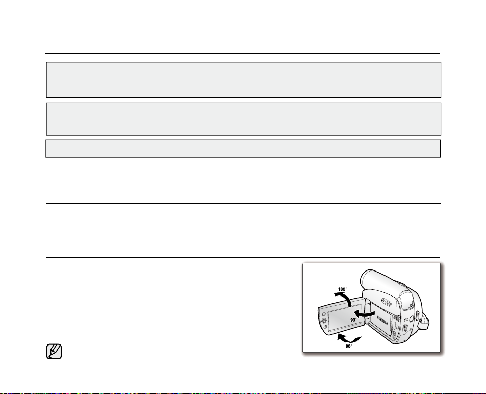
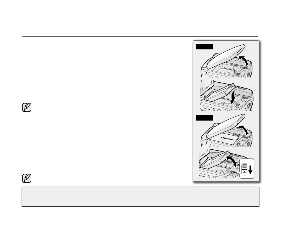
Please rotate the LCD screen carefully as illustrated. Over rotation may
cause damage to the inside of the hinge that connects the LCD screen
to the camcorder.
1.
Open the LCD screen 90 degrees from the camcorder with your finger.
2. Rotate it to the best angle to record or play.
- If you rotate the LCD screen 180 degrees so it is facing forward,
you can close the LCD screen with the display facing out.
- This is convenient during playback operations.
Refer to page 31 to adjust brightness and color of the LCD screen.
ADJUSTING THE LCD SCREEN
AV
DV
BATT.
MENU
W
T
MODE
POWER
CHG
notes and safety instructions
precautions
Warning!
• This camcorder should always be connected to an AC outlet with a protective grounding connection.
• Batteries shall not be exposed to excessive heat such as sunshine, fire or the like.
Caution
Danger of explosion if battery is incorrectly replaced.
Replace only with the same or equivalent type.
If this power supply is used at 240V ac, a suitable plug adaptor should be used.
Page 9

NOTES REGARDING THE LCD SCREEN
Direct sunlight can damage the LCD screen and the inside of the the Lens. Take pictures of the sun only in low
•
light conditions, such as at dusk.
The LCD screen has been manufactured using high precision technology. However, there may be tiny dots (red,
•
blue or green in color) that appear on the LCD screen. These dots are normal and do not affect the recorded picture in any way.
Do not pick up the camcorder by holding the LCD screen or battery pack.
•
SERVICING & REPLACEMENT PARTS
•
Do not attempt to service this camcorder yourself.
•
Opening or removing covers may expose you to dangerous voltage or other hazards.
•
Refer all servicing to qualified service personnel.
•
When replacement parts are required, be sure the service technician has used replacement parts specified by the
manufacturer and having the same characteristics as the original part.
•
Unauthorized substitutions may result in fire, electric shock or other hazards.
NOTES REGARDING CAMCORDER
Do not leave the camcorder exposed to high temperatures (above 60 °C or 140 °F). For example, in a parked car
•
in the sun or exposed to direct sunlight.
Do not let the camcorder get wet. Keep the camcorder away from rain, sea water, and any other form of moisture.
•
If the camcorder gets wet, it may get damaged. Sometimes a malfunction due to exposure to liquids cannot
be repaired.
A sudden rise in atmospheric temperature may cause condensation to form inside the camcorder.
•
- When you move the camcorder from a cold location to a warm location (e.g. from outside to inside during the winter.)
- When you move the camcorder from a cool location to a hot location (e.g. from inside to outside during the summer.)
If the (DEW) protection feature is activated, leave the camcorder for at least two hours in a dry, warm room with
•
the cassette compartment opened and the battery pack removed.
English _ix
Page 10

02_ English
contents
GETTING TO KNOW
YOUR MINIDV CAMCORDER
PREPARATION
INITIAL SETTING :
SYSTEM MENU SETTING
06
12
24
06 What is included with your miniDV camcorder
07 Front & left view
08 Left side view
09 Right & top view
10 Rear & bottom view
11 Using the remote control (SC-D382/D385 only)
12 Using the hand strap & lens cover
13 Installing the button-type battery
14
Using the battery pack
17 Connecting a power source
18 Basic miniDV camcorder operation
19 Screen indicators in Camera/Player modes
20 Screen indicators in M.Cam/M.Player modes
(SC-D383/D385 only)
21 Using the display ( ) button
22 Using the joystick
22 Handling quick menus with the joystick
24 Setting the clock (Clock set)
25 Setting the wireless remote control acceptance (Remote)
(SC-D382/D385 only)
26 Setting the beep sound (Beep Sound)
27 Setting the shutter sound (Shutter Sound)
28 Selecting the OSD language (Language)
29 Viewing the demonstration (Demonstration)
Page 11

INITIAL SETTING :
DISPLAY MENU SETTING
30 Setting the guideline (Guideline)
31 Adjusting the LCD screen (LCD Bright/LCD Color)
32 Displaying the date/time (Date/Time)
33 Setting the tv display (TV display)
BASIC RECORDING
34
ADVANCED RECORDING
44
34 Inserting / ejecting a cassette
34 Various recording techniques
35 Making your first recording
36 Recording with ease for beginners (EASY.Q mode)
37 Zooming in and out
38 Searching quickly for a desired scene
(Setting the zero memory) (SC-D382/D385 only)
39 Self record using the remote control (Setting the Self Timer)
(SC-D382/D385 only)
40 Reviewing and searching a recording
41 Using the fade on and off
42 Auto focus / manual focus
43 Setting the shutter speed & exposure
44 Selecting the record mode & audio mode
(Rec Mode & Audio Mode)
45
Cutting wind noise (WindCut Plus)
46 Selecting the real stereo function (Real Stereo)
47 Setting the program ae (Program AE)
49 Setting the white balance (White Balance)
51 Applying visual effects (Visual Effect)
53 Setting the 16:9 wide mode (16:9 Wide)
54 Using the tele macro (Macro)
English _03
Page 12

04_ English
contents
55 Setting the digital image stabilizer (DIS)
1
56 Using back light compensation mode (BLC)
57 Zooming in and out with digital zoom (Digital Zoom)
58 Using the color nite (C.Nite)
59 Using the light (Light) (SC-D382/D383/D385 only)
60 Recording a photo image on a tape -tape photo recording
61 Searching for a photo image on a tape (Photo Search)
PLAYBACK
62
CONNECTION
68
DIGITAL STILL CAMERA MODE
(SC-D383/D385 only)
72
62 Playing back a tape on the LCD screen
63
Various functions while in Player mode
65 Audio dubbing (SC-D382/D385 only)
66 Dubbed audio playback (Audio Select)
67 Audio effect
68 Playing back a tape on a TV screen
70
Copying a camcorder tape onto a video tape
71 Using the VOICE+ function
72 Using a memory card (usable memory card) (not supplied)
Structure of folders and files on the memory card
73
75 Setting the file number (File No.)
76 Taking a photo image (JPEG) on the memory card
77 Viewing photo images (JPEG)
78 Protection from accidental erasure (Protect)
79 Deleting photo images and moving images (Delete)
81 Formatting a memory card (Format)
Page 13

82 Recording moving images (MPEG) on a memory card
)
84 Playing the moving images (MPEG) on a memory card
(M.Play select)
85 Recording an image from a tape as a photo image
86 Copying a photo image from a tape to a memory card
(Photo Copy)
87 Marking images for printing (Print Mark)
PICTBRIDGE™
(SC-D383/D385 only)
IEEE 1394 DATA TRANSFER
USB INTERFACE
(SC-D383/D385 only)
92
MAINTENANCE
98
TROUBLESHOOTING
SPECIFICATIONS
88 Printing your pictures – using Pictbridge
90 Transferring ieee1394 (I.Link)-DV standard data connections
92 Using USB Interface
94
Selecting the USB device (USB Connect)
95 Installing the software (DV Media Pro program)
96 Connecting to a PC
98 After finishing a recording
Usable cassette tapes
98
99 Cleaning and maintaining the camcorder
100 Using your miniDV camcorder abroad
101 Troubleshooting
103 Setting menu items
105
TM
English _05
Page 14
06_ English
getting to know your miniDV camcorder
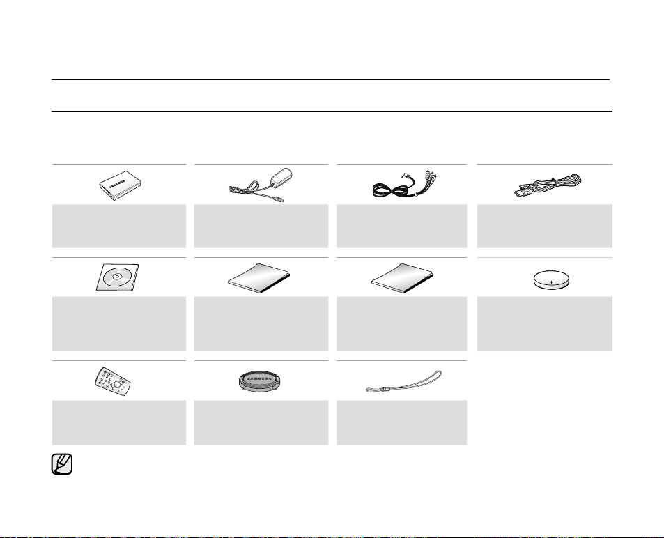
WHAT IS INCLUDED WITH YOUR MINIDV CAMCORDER
Your new Digital Video camcorder comes with the following accessories. If any of these items is missing from your box,
call Samsung’s Customer Care Center at 1-800-SAMSUNG.
✪
The exact appearance of each item may vary by model.
Battery Pack
(IA-BP80W )
AD43-00186A
Software CD
(SC-D383/D385 only)
AD46-00097A
Remote Control
(SC-D382/D385 only)
AD59-00085B
The contents may vary depending on the sales region.
•
Parts and accessories are available at your local Samsung dealer.
•
A memory card is not included. See page 72 for memory cards compatible with your miniDV camcorder.
•
AC Power Adapter
(AA-E9 type)
AD44-00116B
User Manual
AD68-02562A
Lens Cover
AD97-10686A
Audio/Video Cable
AD39-00001A
Quick Start Guide
AD68-02563A
Lens Cover Strap
AD72-00049A
USB Cable
(SC-D383/D385 only)
AD39-00132D
Button-type Battery for
Remote Control
(Type: CR2025)
(SC-D382/D385 only)
AD43-10130H
Page 15
English _07
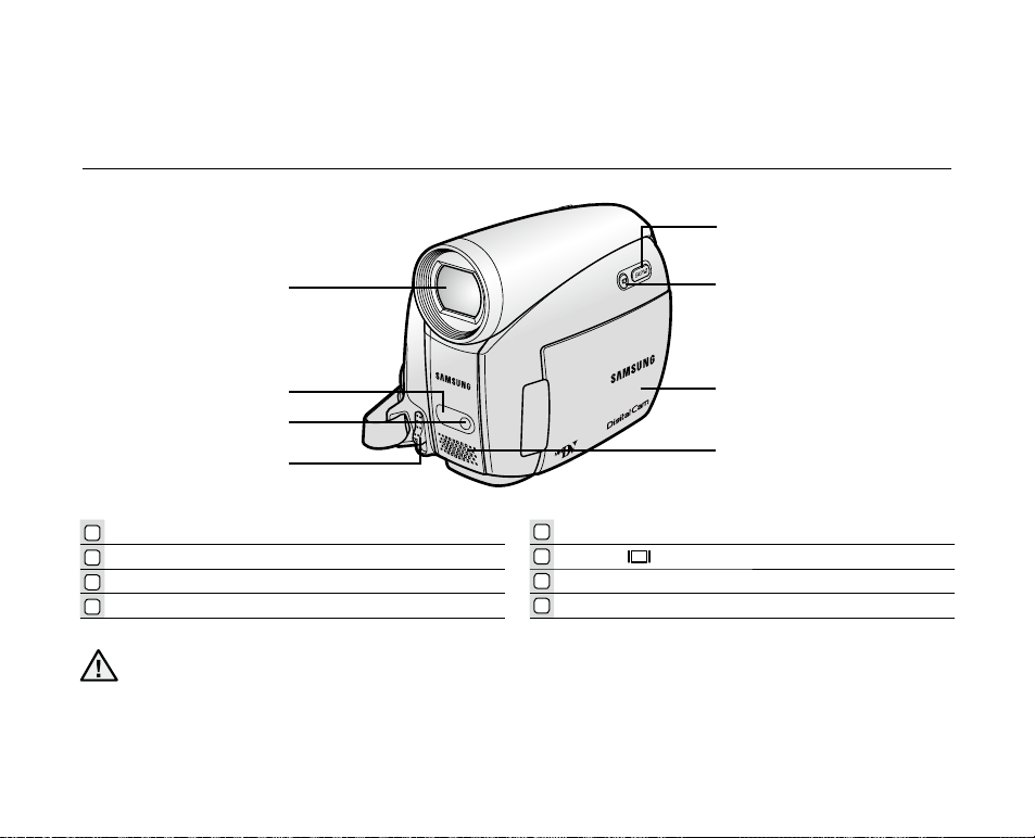
FRONT & LEFT VIEW
OPEN
5
1
2
3
4
Lens
1
Remote sensor (SC-D382/D385 only)
2
Light (SC-D382/D383/D385 only)
3
OPEN switch
4
Be careful not to cover the internal microphone and lens during recording.
CAUTION
5
6
7
8
6
7
8
EASY Q button ➥page 36
Display ( ) button
TFT LCD screen
Internal microphone
Page 16

08_ English
LEFT SIDE VIEW
getting to know your miniDV camcorder
1
MENU button
2
Joystick ( / / / / Select ), (W/T) ➥page 23
3
Recording start/stop button
4
Jack cover (AV/DV jack)
5
Built-in speaker
6
Select (CARD-TAPE) switch (SC-D383/D385 only)
7
Battery pack
8
Battery release (BATT.) switch
AV
DV
BATT.
MENU
W
T
MODE
POWER
CHG
5
7
4
1
2
3
8
6
MODE
TAPECARD
(SC-D383/D385 only)
Page 17

English _09
RIGHT & TOP VIEW
MOD
E
AV
DV
POWER
CHG
VOL
1
2
3
4
5
6
7
Zoom(W/T) / Volume (VOL) lever
1
PHOTO button ➥pages 60,76
2
Recording start/stop button
3
POWER switch
4
5
Jack cover (DC IN, USB (SC-D383/D385 only) jack)
6
Cassette compartment cover
7
Hand strap
Page 18

getting to know your miniDV camcorder
AV
MODE
DC IN
DV
POWER
CHG
REAR & BOTTOM VIEW
1
2
3
4
1
AV jack
2
MODE button
Mode indicator (Camera ( ) / Player ( ) mode)
3
4
DC IN Jack
5
DV (IEEE1394) jack
6
Charging (CHG) indicator
7
USB jack (SC-D383/D385 only)
8
Memory card slot (SC-D383/D385 only)
9
Tripod receptacle
10_ English
5
6
7
Jacks
SC-D383/D385
SC-D381/D382
SC-D383/D385 only
98
AV DV DC IN USB
AV DV DC IN
MMC/SD
Page 19

USING THE REMOTE CONTROL (SC-D382/D385 only)
1
2
3
4
5
6
7
8
9
PHOTO button ➥pages 60,76
1
REC button
2
SELF TIMER button ➥page 39
3
ZERO MEMORY button ➥page 38
4
PHOTO SEARCH button ➥page 61
5
A.DUB button ➥page 65
6
(FF) button
7
(REW) button
8
(PLAY) button
9
The buttons on the remote control function the same as those on the miniDV camcorder.
10
(-) / (+) (Direction) button ➥page 64
11
Display ( )
12
W/T (Zoom) button
13
X2 button ➥page 64
14
DATE/TIME button
15
(SLOW) button
16
(PAUSE) button
17
(STOP) button
18
F. ADV button ➥page 64
button
English _11
Page 20

12_ English
It is very important to ensure that the hand strap has been correctly adjusted before you begin your recording.
The hand strap enables you to:
Hold the camcorder in a stable, comfortable position.
Put your hand in a position where you can easily operate the Recording start/stop button, PHOTO button,
and the Zoom lever.
Hand Strap
Adjusting the Hand Strap
1. Insert the hand strap into the hand strap hook on
the front side of the camcorder and pull its end
through the hook.
2. Insert your hand into the hand strap and adjust its
length for your convenience.
3. Close the hand strap.
Lens Cover
Attaching the Lens Cover
4. Hook up the lens cover with the lens cover strap
as illustrated.
5. Hook up the lens cover strap to the hand strap, and
adjust it following the steps as described for the
hand strap.
6. Close the hand strap.
Installing the Lens Cover after Operation
Press buttons on both sides of the lens cover, then attach it to the camcorder lens.
•
•
preparation
USING THE HAND STRAP & LENS COVER
This section provides information on using this miniDV camcorder: such as how to use the provided accessories,
how to charge the battery, how to set up the operation and screen indicators in each mode.
OPEN
1 2 3
4 5 6
Page 21

English _13
INSTALLING THE BUTTON-TYPE BATTERY
Button-type battery installation for the remote control
(SC-D382/D385 only)
1. Pull out the button-type battery holder toward the direction of
the arrow.
2. Position the button-type battery in the button-type battery holder,
with the positive (
) terminal face up.
3. Reinsert the button-type battery holder.
Precaution regarding the button-type battery
There is a danger of explosion if button-type battery is incorrectly replaced. Replace only with the same or
equivalent type.
Do not pick up the battery using tweezers or other metal tools. This will cause a short circuit.
Do not recharge, disassemble, heat or immerse the battery in water to avoid the risk of explosion.
Keep the button-type Battery out of reach of children. Should a battery be swallowed, seek medical
attention immediately.
•
•
•
WARNING
Page 22
14_ English
Use the IA-BP80W battery pack only
.
The battery pack may be charged a little at the time of purchase
.
Be sure to charge the battery pack before you start using your miniDV camcorder.
Inserting / Ejecting the battery pack
1. Open the LCD screen as shown in the figure.
2. Insert the battery pack into the battery pack slot until it softly clicks.
• Make sure that word mark (SAMSUNG) is facing out while
the camcorder is placed as shown in the figure.
3. Slide the BATT. release switch and pull out the battery pack.
• Gently slide the BATT. release switch in the direction as
shown in the figure.
• Additional battery packs are available at your local Samsung dealer.
• If the miniDV camcorder will not be in use for a while, remove the battery
pack from the miniDV camcorder.
Charging the Battery Pack
1. Slide the POWER switch downwards to turn off the power.
2. Insert the battery pack to the camcorder.
3. Open the jack cover and connect the AC power adaptor to the DC IN jack.
4. Connect the AC power adaptor to a wall socket.
5. Once charged, disconnect the AC power adaptor from the DC IN jack on your
camcorder.
• Even with the power switched off, the battery pack will still discharge if it is
left inserted in the camcorder.
It is recommended that you purchase one or more additional battery packs
to allow continuous use of your miniDV camcorder.
•
•
•
USING THE BATTERY PACK
Use only Samsung-approved battery packs. Do not use batteries from other manufacturers.
Otherwise, there is a danger of overheating, fire or explosion.
Samsung is not responsible for problems occured due to using unapproved batteries.
preparation
POW
ER
BAT
T.
POW
ER
BAT
T.
POWER
CH
BATT.
BATT .
POWER
CH
BATT.
Insert
Eject
Page 23

English _15
Charging, Recording Times with a fully charged battery pack (with no zoom operation,
LCD open, etc.)
Measured times shown in the table are based on model
SC-D385.
(Times for SC-D381/D382/D383/D385 are almost the same.)
The time is only for reference. Figures shown in the table are
measured under Samsung’s test environment, and may differ
from your actual use.
The recording time shortens dramatically in a cold environment.
The continuous recording times in the operating
instructions are measured using a fully charged battery pack at 25 °C (77 °F). As the environmental temperature
and conditions vary, the remaining battery time may differ from the approximate continuous recording times given
in the instructions.
•
•
•
Charging
time
Recording
time
IA-BP80W
Approx.
1hr 20min
Approx.
1hr 20min
Battery
Time
Charging indicator
The color of the LED indicates the power or charging state.
• If the battery pack has been fully charged, the charge indicator
is green.
• If you are charging the battery, the color of the charge indicator
is orange.
• If an error occurs while the battery pack in charging, the charging
indicator blinks orange.
AV
MODE
DC IN
DV
POWER
CHG
OWER
CHG
<Charging indicator>
Page 24

16_ English
preparation
The amount of continuous recording time available depends on:
The type and capacity of the battery pack you are using.
Ambient temperature.
How often the zoom function is used.
Type of use (camcorder/camera/with LCD screen etc.)
It is recommended that you have several batteries available.
To check the remaining battery charge, press and hold the Display ( ) button. ➥page 21
The charging time will vary depending on the remaining battery level.
•
•
•
•
•
•
•
Battery Level Display
The battery level display indicates the amount of power remaining in the battery pack.
a. Fully charged b. 20~40% used
c. 40~80% used d. 80~95% used
e. Completely used (Blinking)
(The Camcorder will turn off soon, change the battery as soon as possible.)
Battery Pack Management
The battery pack should be recharged in an environment between 0 °C (32 °F) and 40°C (104 °F).
The life and capacity of the battery pack will be reduced if it is used in temperatures below 0 °C (32 °F) or left in
temperatures above 40 °C (104 °F) for a long period of time, even when it is fully recharged.
Do not put the battery pack near any heat source (i.e. fire or a heater).
Do not disassemble, apply pressure to, or heat the battery pack.
Do not allow the + and – terminals of the battery pack to be short-circuited. It may cause leakage, heat
generation, induce overheating or fire.
•
•
•
•
•
(Blinking)
Page 25
English _17
Notes regarding the Battery Pack
Please refer to the table on page 15 for approximate continuous recording time.
The recording time is affected by temperature and environmental conditions.
The recording time shortens dramatically in a cold environment, as the environmental temperature and conditions vary.
The continuous recording times in the operating instructions are measured using a fully charged battery pack at
25 °C (77 °F). The remaining battery time may differ from the approximate continuous recording times given in
the instructions.
When purchasing a new battery pack, we recommend buying the same battery pack that is provided
with this camcorder. The battery pack is available at SAMSUNG retailers.
When the battery reaches the end of its life, please contact your local dealer.
Batteries should be handled as chemical waste.
Make sure that the battery pack is fully charged before starting to record.
A brand new battery pack is not charged. Before using the battery pack, you need to charge it completely.
The battery pack may be prone to leakage when fully discharged.
Fully discharging a battery pack damages the internal cells.
To preserve battery power, keep your camcorder turned off when you are not operating it.
If your camcorder is in Camera mode, and it is left in STBY mode without being operated for more than 5
minutes with a tape inserted, it will automatically turn itself off to protect against unnecessary battery discharge.
Do not drop the Battery Pack. Dropping the battery pack may damage it.
•
•
•
•
•
•
•
•
•
•
•
•
CONNECTING A POWER SOURCE
There are two types of power source that can be connected to your camcorder.
- The AC Power Adapter: used for indoor recording.
- The Battery Pack: used for outdoor recording.
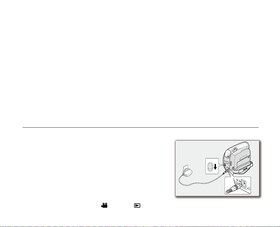
Using a Household Power Source
Connect to a household power source to use the camcorder without
having to worry about the battery power. You can keep the battery pack
attached; the battery power will not be consumed.
1. Slide the POWER switch downwards to turn off the power.
2.
Open the jack cover and connect the AC power adaptor to the DC IN jack.
3. Connect the AC power adaptor to a wall socket.
• The plug and wall socket type may differ according to your
resident country.
4. Slide the POWER switch downwards to turn on the power and press
the MODE button to set Camera (
) or Player ( ).
•
MODE
AV
DV
POWER
CHG
VOL
POWER
2
3
1
Page 26

18_ English
BASIC MINIDV CAMCORDER OPERATION
Turning the miniDV camcorder on and off
You can turn the camcorder on or off by sliding the POWER switch downward.
Slide the POWER switch repeatedly to toggle the power on or off.
Setting the operating modes
•
Set the operation mode by adjusting the MODE button and Select switch
(SC-D383/D385 only) before operating any functions.
1.
Press the MODE button to set Camera(
) or Player( ).
Each press of the MODE button toggles between the Camera (
) mode
and Player (
) mode.
2. Set the Select switch to CARD or TAPE. (SC-D383/D385 only)
- Camera mode (
): To record movie or photo images on a tape. ➥page 19
- Player mode (
): To play movie or photo images on a tape. ➥page 19
-
M.Cam mode (
): To record movie or photo images on a memory card.
➥pages 20, 76 and 82
-
M.Player mode (
): To play movie or photo images on a memory card.
➥pages 20, 77 and 84
•
The operating modes are determined by the position of the MODE button and Select switch (SC-D383/D385
only).
•
Mode Name Camera Mode Player Mode M.Cam Mode M.Player Mode
MODE button
hw
l
hwljhyk
{hwljhyk {
hw{
l
hwljhyk
tvkl tvkl
hw
l
hwljhyk
{hwljhyk {
hw{
l
hwljhyk
tvkl tvkl
Select switch
(SC-D383/D385
only)
{hwljhyk {
hw
l
hwljhyk
{hwljhyk {
hw
l
hwljhyk
hw
l
hwljhyk
hw
l
hwljhyk
preparation
M.Cam Mode : Memory Camera Mode
M.Player Mode : Memory Player Mode
The M.Cam Mode and the M.Player Mode are only available on models SC-D383/D385.
•
•
AV
MODE
DC IN
DV
POWER
CHG
MODE button
POWER switch
Mode indicator
Page 27
English _19
60min
10Sec
0:00:00
C.Nite 1/30
SP
Art
16Bit
No Tape !
STBY
12:00 AM JAN. 1,2008
S
W T
19
1/60
M
1/60
21 3 4 5 6
1718
19
798
10
11
12
13
14
15
16
19
21
20
22
20
21
22
23
24
25
26
3
14
16:9 Wide
26
No Tape !
[11]
12:00 AM JAN. 1,2008
60min
Sound[2]
0:00:46:06
SP
16Bit
STOP
1
5 46
3
7
9
8
VV
2
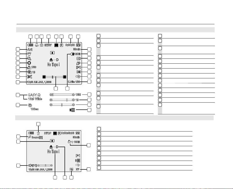
SCREEN INDICATORS IN CAMERA / PLAYER MODES
OSD in Camera Mode
1
Battery Level ➥page 16
2
Tele Macro * ➥page 54
Tape photo recording ➥page 60 /
3
Self timer *
(SC-D382/D385 only)
4
Operating Mode
5
Record Speed Mode ➥page 44
Zero Memory ➥page 38
6
(SC-D382/D385 only)
7
Time counter (movie recording time)
8
Tape Indicator
Remaining Tape
9
(measured in minutes)
10
Audio Mode ➥page 44
Light * ➥page 59
11
(SC-D382/D383/D385 only)
12
BLC (Back Light Compensation)*
➥
OSD in Player Mode
1
Audio Dubbing ➥page 65 (SC-D382/D385 only)
Audio Effect
2
3
DV IN (DV date transfer mode) ➥page 91
4
VOICE+ Indicator ➥page 71
5
Warning Indicator ➥page 101
6
Message Line ➥page 101
7
Volume Control * ➥page 62
8
DEW ➥page 102
9
Dubbed Audio Playback ➥page 66
page 56
➥
page 39
➥
page 67
13
WindCut Plus * ➥page 45
Fade ➥page 41/
14
Remote ➥page 25 (SC-D382/D385 only)
USB * ➥page 96
15
(SC-D383/D385 only)
16
C.Nite * ➥page 58
17
Real Stereo ➥page 46
18
Zoom Position * ➥page 37
19
Date/Time ➥page 32
20
Manual Focus * ➥page 42
21
Manual Exposure * ➥page 43
22
Shutter Speed * ➥page 43
23
White Balance * ➥page 49
24
Program AE * ➥page 47
25
DIS * ➥page 55
Visual Effects Mode * ➥page 51
26
EASY.Q *
16:9 Wide
➥
page 36
➥
page 53
Page 28
20_ English
4
10Sec
No Tape !
Art
10134
60min
12:00 AM JAN. 1,2008
W T
19
21 3
No Memory Card !
4
12:00 AM JAN. 1,2008
[11]
0:00:00
STOP
SMOV0001
2
1
3
4
No Memory Card !
12:00 AM JAN. 1,2008
800X600
2/30
Slide
002
100-0001
7
8
5 6
9
No Memory Card !
preparation
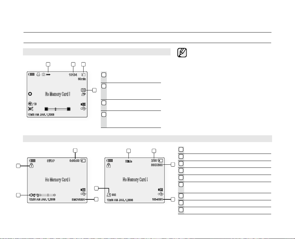
SCREEN INDICATORS IN M.CAM / M.PLAYER MODES (SC-D383/D385 ONLY)
OSD indicators shown here are
•
based on model SC-D385.
The screen to the left is an example;
•
it is different from the actual display.
The OSD indicators are based
•
on memory capacity of 2GB
(SC-D383/D385 only).
For enhanced performance, the
•
display indications and the order
are subject to change without
prior notice.
Functions marked with * will not
•
be retained when the miniDV
camcorder is powered on after
turning it off.
1
Time counter (movie recording time)
2
File number of the moving image
3
Volume Control
4
Erase Protection Indicator ➥page 78
5
Silde ➥page 77
6
Image Counter (Current photo image/
Total number of recordable photo images)
7
Photo image size ➥page 73
8
Folder Number - File Number ➥page 75
9
Print Mark ➥page 87
*
➥
page 84
(Movie images)
OSD in M.Cam Mode
Image Recording and
1
Loading Indicator
Image Counter (Total
2
number of recordable
photo images)
CARD (Memory Card)
3
Indicator
Light ➥page 59
4
(SC-D382/D383/D385
only)
OSD in M.Player Mode
(Photo images)
Page 29

English _21
USING THE DISPLAY ( ) BUTTON
You can switch between the on-screen information display modes: Press the Display ( ) button.
Switching the information display mode
You can switch between the on-screen information display modes:
Press the Display ( ) button.
The full and minimum display modes will alternate.
Full display mode: All information will appear.
Minimum display mode: Only operating status indicators will appear.
Checking the remaining battery
Press and hold the Display ( ) button while charging with the power off.
After a while, the charging status will be displayed on the LCD screen for
7 seconds.
The battery charge status is given as reference and is an estimation.
It may differ depending on the battery capacity and temperature.
•
•
•
•
AV
DV
BATT.
MENU
W
T
MODE
POWER
CHG
Battery Info
Battery chargedBattery charged
0% 50% 100%
Page 30
22_ English
USING THE JOYSTICK
Used for playback, pausing, fast forwarding, and rewinding. Also used as directional
buttons (up, down, left, right) and to make a selection when selecting movie, photo
images or menus.
1. Move the Joystick (
/ ) up or down.
2. Move the Joystick (
/ ) left or right.
Confirm your selection by pressing Joystick.
For more information on the OSD menus displayed using the Joystick
(
/ / / ), see page 23.
•
preparation
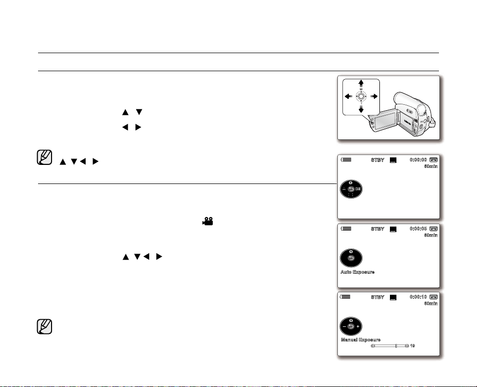
HANDLING QUICK MENUS WITH THE JOYSTICK
Using the Joystick, you can easily access frequently used menus without using
the MENU button.
✪
Follow the instructions below to use each of the menu items listed after this page.
For example: setting the Exposure in Camera (
) mode
1. Press the Joystick.
Quick menu is displayed.
2. Press the Joystick (
/ / / ) to control the setting.
Moving the Joystick up toggles between "Auto Exposure" and "Manual
Exposure".
3. Press the Joystick to confirm your selection.
Press the Joystick button to exit the quick menu according to the selected
mode.
There are some functions you cannot activate simultaneously when using
Joystick. You cannot select the menu items grayed out on the screen
.
Accessible items in menu and quick menu vary depending on the operation
mode.
•
•
•
•
•
A
V
DV
B
ATT
.
MENU
W
T
MODE
POW
ER
CHG
16Bit
10Sec
S
60min
0:00:00
SP
STBY
16Bit
10Sec
S
60min
0:00:05
SP
STBY
Auto Exposure
16Bit
10Sec
S
60min
0:00:10
SP
STBY
Manual Exposure
19
Page 31

English _23
HANDLING QUICK MENUS WITH THE JOYSTICK
Quick Menu In Camera /Player modes
Joystick Camera ( ) Mode Player ( ) Mode
Input
OK
Status
Return / Selection / Exit the menu
-
Exposure - - - - -
Focus - STOP STOP STOP STOP
Shutter REW REW REW REW REW
Fade FF FF FF FF FF
STOP PLAY PAUSE FF REW
PLAY PAUSE PLAY PLAY PLAY
Quick Menu In M.Cam / M.Player modes (SC-D383/D385 only)
Joystick
Input
OK
M.Cam (
Status
) Mode
-
Exposure - - - - -
Focus
-
-
Return/
Selection/Exit
the menu
( ) Mode (Movie images)
M.Player
STOP PLAY PAUSE FF REW
Thumbnail
Previous
Next Skip FF FF FF FF
PLAY PAUSE PLAY PLAY PLAY
STOP STOP STOP STOP
Skip
REW REW REW REW
M. Player (
(Photo
Previous Skip
)
Mode
images)
-
Delete
Thumbnail
Next Skip
Slide Show
Page 32

24_ English
Clock setup works in Camera / Player / M.Cam / M.Player modes. ➥page 18
Set the date and time when using this camcorder for the first time.
1. Set the Select switch to CARD or TAPE. (SC-D383/D385 only)
2. Press the MODE button to set Camera (
) or Player ( ).
3. Press the MENU button.
The menu list will appear.
4. Move the Joystick (
/ ) up or down to select "System", then press the
Joystick or move the Joystick (
)to the right.
5. Move the Joystick (
/ ) up or down to select "Clock Set", then press the
Joystick.
The year will be highlighted first.
6. Move the Joystick (
/ ) up or down to set the current year, then press the
Joystick.
The month will be highlighted.
7. You can set the month, day, hour and minute following the same procedure after
setting the year.
8. Press the Joystick after setting the minutes.
The message "Complete !" is displayed.
9. To exit, press the MENU button.
You can set the year up to 2037.
Turning the date and time display on/off
To switch the date and time display on or off, access the menu and change
the date/time display mode. ➥page 32
•
•
•
•
•
•
•
•
SETTING THE CLOCK (CLOCK SET)
initial setting : system menu setting
Display illustrations in this manual
- OSD illustrations of SC-D385 are used in this manual.
- Some of the OSD items shown in this manual may differ slightly from the actual
items on your camcorder.
BATT
.
CHG
MODE
TAPECARD
A
V
DV
B
ATT
.
M
ENU
W
T
MO
DE
PO
W
ER
CHG
Adjust Select Exit
Remote
Beep Sound
Shutter Sound
Language
Demonstration
Camera Mode
MENU
System
Clock Set
JAN 1
12 : 00 AM
2008
2008
Move Select Exit
Remote
Beep Sound
Shutter Sound
Language
Demonstration
Camera Mode
MENU
System
Clock Set
Complete !
JAN 1
12 : 00 AM
2008
(SC-D383/D385 only)
Page 33

English _25
The remote function works in Camera / Player / M.Cam / M.Player modes.
➥
page 18
The remote function allows you to enable or disable the remote control for use with
the camcorder.
1. Set the Select switch to CARD or TAPE. (SC-D385 only)
2. Press the MODE button to set Camera (
) or Player ( ).
3. Press the MENU button.
The menu list will appear.
4. Move the Joystick (
▲ / ▼
)
up or down to select "System", then press the
Joystick or move the Joystick ()to the right.
5. Move the Joystick (▲ /
▼
)
up or down to select "Remote", then press the
Joystick.
6. Move the Joystick (▲ /
▼
)
up or down to select "On" or "Off", then press the
Joystick.
7. To exit, press the MENU button.
If you set the "Remote" to "Off" in the menu and try to use it, the remote
control indicator (
) will blink for 3 seconds on the LCD screen and then
disappear.
•
•
•
SETTING THE WIRELESS REMOTE CONTROL ACCEPTANCE (REMOTE)
(SC-D382/D385 only)
Move Select Exit
Remote
Beep Sound
Shutter Sound
Language
Demonstration
Camera Mode
MENU
System
Clock Set
� On
� On
� On
� English
�
On
Move Select Exit
Remote
Beep Sound
Shutter Sound
Language
Demonstration
Camera Mode
MENU
System
Clock Set
Off
✔ On
BATT
.
CHG
MODE
TAPECARD
A
V
DV
B
ATT
.
M
ENU
W
T
MO
DE
PO
W
ER
CHG
(SC-D385 only)
Page 34

26_ English
The beep sound function works in Camera / Player / M.Cam / M.Player modes.
➥
page 18
You can turn the beep sound on or off, when on, each press of a button sounds a
beep.
1. Set the Select switch to CARD or TAPE. (SC-D383/D385 only)
2. Press the MODE button to set Camera (
) or Player ( ).
3. Press the MENU button.
The menu list will appear.
4. Move the Joystick (
▲ / ▼
)
up or down to select "System", then press the
Joystick or move the Joystick ()to the right.
5. Move the Joystick (▲ /
▼
)
up or down to select "Beep Sound", then press
the Joystick.
6. Move the Joystick (▲ /
▼
)
up or down to select "On" or "Off", then press the
Joystick.
7. To exit, press the MENU button.
•
•
•
SETTING THE BEEP SOUND (BEEP SOUND)
initial setting : system menu setting
When beep sound is set to off, the power on/off sound is off.
Move Select Exit
Remote
Beep Sound
Shutter Sound
Language
Demonstration
Camera Mode
MENU
System
Clock Set
Off
✔ On
BATT
.
CHG
MODE
TAPECARD
A
V
DV
B
ATT
.
M
ENU
W
T
MO
DE
PO
W
ER
CHG
Move Select Exit
Remote
Beep Sound
Shutter Sound
Language
Demonstration
Camera Mode
MENU
System
Clock Set
� On
� On
� On
� English
�
On
(SC-D383/D385 only)
Page 35

English _27
The shutter sound function works in Camera / Player / M.Cam modes. ➥page 18
You can turn the shutter sound on or off, when on, with each press of the PHOTO
button, the shutter will sound.
1. If you press the MODE button to set it to Camera (
), set the Select switch to
either CARD or TAPE.
If you press the MODE button to set it to Player (
), set the Select switch to
TAPE.
2. Press the MENU button.
The menu list will appear.
3. Move the Joystick (
▲ / ▼
)
up or down to select "System", then press the
Joystick or move the Joystick ()to the right.
4. Move the Joystick (▲ /
▼
)
up or down to select "Shutter Sound", then press
the Joystick.
5. Move the Joystick (▲ /
▼
)
up or down to select "On" or "Off", then press the
Joystick.
6. To exit, press the MENU button.
•
•
•
SETTING THE SHUTTER SOUND (SHUTTER SOUND)
Move Select Exit
Remote
Beep Sound
Shutter Sound
Language
Demonstration
Camera Mode
MENU
System
Clock Set
Off
✔
On
BATT
.
CHG
MODE
TAPECARD
A
V
DV
B
ATT
.
M
ENU
W
T
MODE
PO
W
ER
CHG
Move Select Exit
Remote
Beep Sound
Shutter Sound
Language
Demonstration
Camera Mode
MENU
System
Clock Set
� On
� On
� On
� English
�
On
(SC-D383/D385 only)
Page 36

28_ English
SELECTING THE OSD LANGUAGE (LANGUAGE)
The Language function works in Camera / Player / M.Cam / M.Player modes.
➥
page 18
You can select the desired language to display the menu screen and the messages.
1. Set the Select switch to CARD or TAPE. (SC-D383/D385 only)
2. Press the MODE button to set Camera (
) or Player ( ).
3. Press the MENU button.
The menu list will appear.
4. Move the Joystick (
▲ / ▼
)
up or down to select "System", then press the
Joystick or move the Joystick ()to the right.
5. Move the Joystick (▲ /
▼
)
up or down to select "Language", then press the
Joystick.
The available language options are listed.
English / Français / Español / Deutsch / Italiano / Português / Polski /
Nederlands / Magyar / Svenska /
/ /
/ Iran / Русский /
Українська /
/ Suomi / Türkçe / Norwegian / Danish / Czech / Slovakia
6. Move the Joystick (
▲ / ▼
)
up or down to select the desired OSD language,
then press the Joystick.
The OSD language is refreshed in the selected language.
7. To exit, press the MENU button.
Language options may be changed without prior notice.
•
•
•
•
•
•
initial setting : system menu setting
Move Select Exit
Remote
Beep Sound
Shutter Sound
Language
Demonstration
Camera Mode
MENU
System
Clock Set
✔ English
Français
Español
Deutsch
Italiano
Português
BATT
.
CHG
MODE
TAPECARD
A
V
DV
B
ATT
.
M
ENU
W
T
MODE
PO
W
ER
CHG
Move Select Exit
Remote
Beep Sound
Shutter Sound
Language
Demonstration
Camera Mode
MENU
System
Clock Set
� On
� On
� On
� English
�
On
(SC-D383/D385 only)
Page 37

English _29
Demonstration automatically shows you the major functions that are included with
your camcorder so that you may use them more easily.
The demonstration function may only be used in the Camera mode without a tape
inserted in the camcorder. ➥page 18
Before you begin: Make sure that there is no tape inserted in the camcorder.
➥
page 34
The demonstration operates repeatedly until the demonstration mode is switched off
.
1. Set the Select switch to TAPE. (SC-D383/D385 only)
2. Press the MODE button to set Camera (
).
3. Press the MENU button.
The menu list will appear.
4. Move the Joystick (
▲ / ▼
)
up or down to select "System", then press the
Joystick or move the Joystick ()to the right.
5. Move the Joystick (
▲ / ▼
)
up or down to select "Demonstration", then press
the Joystick.
6.
Move the Joystick (▲ /
▼
)
up or down to select "On", then press the Joystick
.
7. Press the MENU button.
The demonstration will begin.
8. To quit the demonstration, press the MENU button.
The demonstration function is automatically activated when the camcorder
is left idle for more than 10 minutes after switching to the Camera mode
(if no tape is inserted in the camcorder).
If you press other buttons (MENU,
Joystick
, EASY.Q...) during the
demonstration mode, the demonstration stops temporarily and resumes
10 minutes later if you do not operate any other functions.
The demonstration mode displays in 4:3 aspect ratio on the LCD screen.
•
•
•
•
•
•
•
•
•
VIEWING THE DEMONSTRATION (DEMONSTRATION)
BATT
.
CHG
MODE
TAPECARD
Move Select Exit
Remote
Beep Sound
Shutter Sound
Language
Demonstration
Camera Mode
MENU
System
Clock Set
Off
✔
On
Move Select Exit
Remote
Beep Sound
Shutter Sound
Language
Demonstration
Camera Mode
MENU
System
Clock Set
� On
� On
� On
� English
�
On
SAMSUNG Camcorder is...
Demonstration
34x Optical Zoom
1200x Digital Zoom
Multi-Visual Effect
(SC-D383/D385 only)
Page 38

30_ English
initial setting : display menu setting
SETTING THE GUIDELINE (GUIDELINE)
Adjusting the LCD screen works in Camera / M.Cam modes. ➥page 18
Guideline displays a certain pattern on the LCD screen so that you can easily set
the image composition when recording movie or photo images.
The miniDV camcorder provides 3 types of guidelines.
1. Set the Select switch to CARD or TAPE. (SC-D383/D385 only)
2. Press the MODE button to set Camera (
).
3. Press the MENU button.
The menu list will appear.
4. Move the Joystick (
▲ / ▼
)
up or down to select "Display", then press the
Joystick or move the Joystick ()to the right.
5. Move the Joystick (
▲ / ▼
)
up or down to select "Guideline", then press the
Joystick
.
6. Move the Joystick (
▲ / ▼
)
up or down to select the guideline display type,
then press the
Joystick
.
Settings Contents
On-screen
display
Off
Disables the function. None
Cross
Enables you to center the subject for proper recording.
Grid
Enables you to place the subject in the center square fo r proper
positioning.
Safety
Zone
Enables you to place the subject within a safety zone which prevents
it being cut when editing in 4:3 mode for left and right and 2.35:1 for
top and bottom.
7. To exit, press the MENU button.
Positioning the subject at the cross point of the guideline makes a balanced composition.
Guidelines are not recorded on the images.
•
•
•
•
•
•
Move Select Exit
LCD Bright
LCD Color
Date/Time
TV Display
Camera Mode
MENU
Display
Guideline
� Off
� Off
� On
Move Select Exit
LCD Bright
LCD Color
Date/Time
TV Display
Camera Mode
MENU
Display
Guideline
✔ Off
Cross
Grid
Safety Zone
BATT
.
CHG
MODE
TAPECARD
A
V
DV
B
ATT
.
M
ENU
W
T
M
ODE
PO
W
ER
CHG
(SC-D383/D385 only)
Page 39

English _31
ADJUSTING THE LCD SCREEN (LCD BRIGHT/LCD COLOR)
Adjusting the LCD screen works in Camera / Player / M.Cam / M.Player modes.
➥
page 18
Your camcorder is equipped with a 2.7 inch wide color Liquid Crystal Display (LCD)
screen, which enables you to view what you are recording or playing back directly.
Depending on the conditions under which you are using the camcorder (indoors or
outdoors for example), you can adjust:
-
"LCD Bright"
- "LCD Color"
1. Set the Select switch to CARD or TAPE. (SC-D383/D385 only)
2. Press the MODE button to set Camera (
) or Player ( ).
3. Press the MENU button.
The menu list will appear.
4. Move the Joystick (
▲ / ▼
)
up or down to select "Display", then press the
Joystick or move the Joystick ()to the right.
5. Move the Joystick (
▲ / ▼
)
up or down to select "LCD Bright" or "LCD Color",
then press the Joystick.
6. Move the Joystick (
▲ / ▼
)
up or down to adjust the value of the selected item,
"LCD Bright" or "LCD Color", then press the Joystick.
You can set values for "LCD Bright" and "LCD Color" between "0" and "35"
.
7. To exit, press the MENU button.
Adjusting the LCD screen does not affect the brightness and color of the
image to be recorded.
•
•
•
•
•
•
Adjust S elect Exit
LCD Bright
LCD Color
Date/Time
TV Display
Camera Mode
MENU
Display
Guideline
[18]
BATT.
CHG
MODE
TAPECARD
A
V
DV
B
ATT
.
M
ENU
W
T
MODE
PO
W
ER
CHG
Adjust Se lect Exit
LCD Bright
LCD Color
Date/Time
TV Display
Camera Mode
MENU
Display
Guideline
[18]
(SC-D383/D385 only)
Page 40

32_ English
DISPLAYING THE DATE / TIME (DATE / TIME)
The date/time function works in Camera / Player / M.Cam / M.Player modes.
➥
page 18
The date and time are automatically recorded on a special data area of the tape.
1. Set the Select switch to CARD or TAPE. (SC-D383/D385 only)
2. Press the MODE button to set Camera (
) or Player ( ).
3. Press the MENU button.
The menu list will appear.
4. Move the Joystick (
▲ / ▼
)
up or down to select "Display", then press the
Joystick or move the Joystick ()to the right.
5. Move the Joystick (
▲ / ▼
)
up or down to select "Date/Time", then press
the Joystick.
6. Move the Joystick (
▲ / ▼
)
up or down to select the date/time display type,
then press the Joystick.
Date/Time display types: "Off", "Date", "Time", "Date&Time".
7. To exit, press the MENU button.
On charging the built-in rechargeable battery
Your camcorder has a built-in rechargeable battery to retain the date, time,
and other settings even when the power is off. The built-in rechargeable
battery is always charged while your camcorder is connected to the wall
outlet via the AC power adaptor or while the battery pack is attached.
The rechargeable battery will be fully discharged in about 3 months if you do
not use your camcorder at all. Use your camcorder after charging the built-in
rechargeable battery. If the built-in rechargeable battery is not charged,
any data that you have input will not be backed up and the date/time appears on
the screen as "12:00 AM JAN. 1.2008" (when "Date/Time" display is set to "On").
The date/time will read "12:00 AM JAN. 1.2008" in the following conditions:
-
When the built-in rechargeable battery becomes weak or dead.
-
If the movie or photo recording was made before setting the date/time in the
miniDV camcorder
.
The DATE/TIME button exists on the remote control as well. (SC-D382/D385 only)
Press it once to display the date "
JAN. 1.2008
", press it twice to display the time and
press it again to display both time and date on the screen.
•
•
•
•
•
•
•
initial setting:display menu setting
Move Select Exit
LCD Bright
LCD Color
Date/Time
TV Display
Camera Mode
MENU
Display
Guideline
✔
Off
Date
Time
Date&Time
BATT.
CHG
MODE
TAPECARD
A
V
DV
B
ATT
.
M
ENU
W
T
M
ODE
PO
W
ER
CHG
Move Select Exit
LCD Bright
LCD Color
Date/Time
TV Display
Camera Mode
MENU
Display
Guideline
� Off
� Off
� On
(SC-D383/D385 only)
Page 41

English _33
SETTING THE TV DISPLAY (TV DISPLAY)
The TV Display function works in Camera / Player / M.Cam / M.Player modes.
➥
page 18
You can select the output path of the OSD (On Screen Display).
-
"Off": The OSD appears on the LCD screen only.
- "On": The OSD appears on the LCD screen and TV.
(Connecting to a TV
➥
pages 69~70)
- Use the Display(
) button to turn the OSD on/off on the LCD screen
and TV.
➥
page 21
1. Set the Select switch to CARD or TAPE. (SC-D383/D385 only)
2. Press the MODE button to set Camera (
) or Player ( ).
3. Press the MENU button.
The menu list will appear.
4. Move the Joystick (
▲ / ▼
)
up or down to select "Display", then press the
Joystick or move the Joystick () to the right.
5. Move the Joystick (
▲ / ▼
)
up or down to select "TV Display", then press the
Joystick.
6. To activate TV Display function, move the Joystick (
▲ / ▼
)
up or down to select
"On" or "Off", then press the Joystick.
7. To exit, press the MENU button.
•
•
•
Move Select Exit
LCD Bright
LCD Color
Date/Time
TV Display
Camera Mode
MENU
Display
Guideline
Off
✔
On
A
V
DV
B
ATT
.
M
ENU
W
T
M
ODE
PO
W
ER
CHG
BATT.
CHG
MODE
TAPECARD
(SC-D383/D385 only)
Move Select Exit
LCD Bright
LCD Color
Date/Time
TV Display
Camera Mode
MENU
Display
Guideline
� Off
� Off
� On
Page 42

34_ English
When inserting a tape or closing the cassette compartment,
do not apply excessive force, as it may cause a malfunction.
Do not use any tape other than DV cassettes.
1. Connect a power source and slide the OPEN switch.
The cassette compartment cover opens automatically.
2. Inserting a Cassette: Insert a tape into the cassette
compartment with the tape window facing outward and the
protection tab toward the top.
Ejecting a Cassette: Remove the cassette tape, which is
automatically ejected by pulling the cassette out.
3. Press the area marked PUSH on the cassette compartment
cover until it clicks into place.
The cassette is loaded automatically.
4. Close the cassette compartment cover.
•
•
•
•
INSERTING / EJECTING A CASSETTE
basic recording
VARIOUS RECORDING TECHNIQUES
In some situations different recording techniques may be required.
1. General recording.
2. Downward recording.
Making a recording with a top view of the LCD screen.
3. Upward recording.
Making a recording viewing the LCD screen from below.
4. Self recording.
Making a recording viewing the LCD screen from the front.
Please rotate the LCD screen carefully as excessive rotation
may cause damage to the inside of the hinge that connects
the LCD screen to the camcorder.
•
•
•
OPEN
1 2
3 4
1 2
3 4
Page 43

English _35
MAKING YOUR FIRST RECORDING
1. Connect a power source to the camcorder. ➥page 17
(A battery pack or a AC power adapter) ➥pages 14,17
Insert a cassette.
➥
page 34
If you want to record on a memory card, insert the
memory card. (SC-D383/D385 only) ➥page 72
2. Remove the lens cover.
3. Slide the POWER switch downwards to turn on the
power.
Open the LCD screen.
Set the Select switch to CARD or TAPE.
(SC-D383/D385 only)
Press the MODE button to set Camera (
).
- Make sure that STBY is displayed.
If the write protection tab of the cassette is open
(set to save), STOP and "Protection!" will be
displayed. Release the write protection tab to
record.
Make sure the image you want to record appears on the LCD screen.
Make sure the battery level indicates that there is enough
remaining power for your expected recording time.
You can select a record mode of your choice.
➥
page 44
4. To start recording, press the Recording start/stop button.
"REC
●
" is displayed on the LCD screen.
To stop recording, press the
Recording start/stop button again.
"STBY" is displayed on the LCD screen.
Eject the battery pack when you finish the recordings to prevent unnecessary battery power consumption.
The miniDV camcorder provides two Recording start/stop buttons. One is on the rear side of the
camcorder and the other one is on the LCD panel. Select the Recording start/stop button according to
the use.
•
•
•
•
•
•
•
•
•
•
•
•
•
10Sec
16Bit
S
No Tape !
W T
29
1/50
M
60min
0:00:00
SP
16:9 Wide
REC
MODE
POWER
CHG
VOL
MENU
OPEN
OPE
N
Page 44

36_ English
RECORDING WITH EASE FOR BEGINNERS (EASY Q MODE)
The EASY Q function works only in Camera mode. ➥page 18
With the EASY Q function, most of the miniDV camcorder settings are automatically adjusted, which frees you
from making detailed adjustments.
1. Set the Select switch to TAPE. (SC-D383/D385 only)
2. Press the MODE button to set Camera (
).
3. Press the EASY Q button.
When you press the EASY Q button, most functions turn off and the following
functions are set to "Auto" (DIS, Focus, White Balance, Exposure, Program AE,
Shutter)
The EASY Q and DIS(
) indicators appear on the screen at the same time.
4. Press the Recording start/stop button to start recording.
Recording will begin using the basic automatic settings.
To cancel the EASY Q mode
Press the EASY Q button again.
The EASY Q and DIS(
) indicators disappear from the screen.
Almost all the settings will return to the settings that were set prior to activating
EASY Q mode.
You cannot cancel the EASY.Q mode during recording.
Menu button unavailable during EASY.Q operation
The MENU button is not available because the items are automatically set.
The "Release the Easy.Q!" messages may appear if unavailable operations
are attempted.
- MENU button
Taking a photo image using the PHOTO button while EASY.Q is set releases
the DIS function.
•
•
•
•
•
•
•
•
•
•
basic recording
OPEN
BATT.
CHG
MODE
TAPECARD
10Sec
16Bit
S
No Tape !
W T
29
1/50
M
60min
0:00:00
SP
STBY
(SC-D383/D385 only)
Page 45

English _37
ZOOMING IN AND OUT
The zoom function works in both Camera and M.Cam modes. ➥page 18
Use the zoom function for close-up or wide-angle recording.
This miniDV camcorder allows you to record using optical 34x power zoom
and 1200x digital zoom.
To zoom in
Slide the Zoom lever towards T (telephoto).
(Or move the Joystick down ( T
)
on the LCD panel.)
To zoom out
Slide the Zoom lever towards W (wide-angle).
(Or move up the Joystick ( W
)
on the LCD panel.)
•
•
•
The farther you slide the Zoom lever, the quicker the zoom action.
Be sure to keep your finger on the Zoom lever. If you move your finger off the Zoom lever, the operation
sound of the Zoom lever may be also recorded.
Focusing may become unstable during zooming. In this case, set the zoom before recording and lock the
focus by using the manual focus, then zoom in or out during recording. ➥page 42
The minimum possible distance between camcorder and subject while maintaining sharp focus is about
1 cm (about 0.39 inch) for wide angle and 50 cm (about 19.68 inch) for telephoto.
Optical zoom preserves the movie quality, but during digital zoom the quality of image may suffer.
When you zoom into a subject close to the lens, the miniDV camcorder may automatically zoom out
depending on the distance to the subject. In this case, set "Macro" to "On." ➥page 54
•
•
•
•
•
•
MODE
P
O
W
E
R
C
H
G
VOL
M
EN
U
TELE
WIDE
W T
Page 46

38_ English
SEARCHING QUICKLY FOR A DESIRED SCENE (SETTING THE ZERO MEMORY)
(SC-D382/D385 only)
The zero memory function works in both Camera and Player modes. ➥page 18
You can mark a point on a tape that you want to return to following playback.
1. Set the Select switch to TAPE. (SC-D385 only)
2. Press the MODE button to set Camera (
) or Player ( ).
3. Press the ZERO MEMORY button on the remote control before recording or
during playback at the point where you wish to return.
The time code is changed to a tape counter that is set to zero memory with
the zero memory (
0:00:00 ) indicator displayed.
If you want to cancel the zero memory function, press the ZERO MEMORY
button again.
4. Finding the zero position.
When you have finished playback, fast forward or rewind the tape in stop mode.
The tape stops automatically when it reaches the zero position.
When you have finished recording, press the MODE button to set Player (
)
and press the (REW) button.
The tape stops automatically when it reaches the zero position.
5. The tape counter with the zero memory (
) indicator disappears from the
display and the tape counter is changed to the time code.
In the following situations, zero memory mode may be canceled automatically:
- At the end of the section marked with the zero memory function.
- When the tape is ejected.
- When you remove the battery pack or power supply.
The zero memory may not function correctly where there is a break between
recordings on the tape.
The zero memory function is available only when using the remote control.
•
•
•
•
•
•
•
•
•
basic recording
BATT.
CHG
MODE
TAPECARD
16BIt
S
10Sec
C.Nite 1/30
60min
0:00:30
SP
STBY
16:9 Wide
(SC-D385 only)
Page 47

English _39
SELF RECORD USING THE REMOTE CONTROL (SETTING THE SELF TIMER)
(SC-D382/D385 only)
The SELF TIMER function works only in Camera mode. ➥page 18
When you use the SELF TIMER function on the remote control, the recording begins automatically in 10 seconds.
1. Set the Select switch to TAPE. (SC-D385 only)
2. Press the MODE button to set Camera (
).
3. Press the SELF TIMER button.
The (
) indicator is displayed.
4. To record movie images, press the Recording start/stop button.
Self timer starts counting down from 10. At this moment, recording indicator
blinks with a beep sound.
At the last second of the countdown, recording starts automatically.
If you want to cancel the self timer function before recording, press the
SELF TIMER button again.
Do not obstruct the remote control sensor by putting obstacles between
the remote control and miniDV camcorder.
The remote control maximum range is 4 to 5m (13 to17 ft).
The effective remote control angle is up to 30 degrees left /right from the
center line.
Using a tripod (not supplied) is recommended during self record.
•
•
•
•
•
•
•
•
•
•
BATT.
CHG
MODE
TAPECARD
16BIt
S
10Sec
C.Nite 1/30
60min
0:00:30
SP
STBY
10Sec
16:9 Wide
(SC-D385 only)
Page 48

40_ English
REVIEWING AND SEARCHING A RECORDING
basic recording
The Rec Search function works only in Camera mode. ➥page 18
Used to review previously recorded images or to find a point to record a new image in the STBY mode.
Record Search (Joystick
)
1. Set the Select switch to TAPE. (SC-D383/D385 only)
2. Press the MODE button to set Camera (
).
3. To start recording, press the Recording start/stop button.
4. Set to STBY mode by pressing Recording start/stop button again.
5. To perform the backward search:
Move the Joystick () to the left.
-
While you press and hold the Joystick (), the selected images will be played
in reverse order. Press and release the Joystick () to play the images in
reverse order for 3 seconds before resetting the play order to normal.
To perform the normal search:
Move the Joystick () to the right.
- While you press and hold the Joystick (), the selected images will be
played in normal order. To resume recording when your record search
is done, press the Recording start/stop button.
Mosaic shaped distortion may appear on the screen while in Record Search mode.
•
•
•
•
MODE
POWER
CHG
VOL
MEN
U
16BIt
60min
0:00:00
SP
16:9 Wide
Page 49

English _41
USING THE FADE ON AND OFF
The Fade function works only in Camera mode. ➥page 18
You can give your recording a professional look by using special effects such as fade in at the beginning of a
sequence or fade out at the end of a sequence.
To Start Recording
1. Set the Select switch to TAPE. (SC-D383/D385 only)
2. Press the MODE button to set Camera (
).
3. Before recording, press the Joystick
and
then move the Joystick ()
to the right.
Move the Joystick () to the right fade function to select "Fade On".
4. Press the Recording start/stop button and at the same time release the
Fade function.
Recording starts and the picture and sound gradually appear. (Fade In)
To Stop Recording
5. When you want to stop recording with fade out, press the Joystick
,
then move the Joystick () to the right.
Move the Joystick () to the right fade function to select "Fade On".
6. Press the Recording start/stop button to stop recording.
The picture and sound gradually disappear. (Fade Out)
•
•
•
•
•
•
Fade Out (Approx. 4 seconds)
Fade In (Approx. 4 seconds)
MODE
POWE
R
C
H
G
V
O
L
M
EN
U
10Sec
16Bit
S
60min
0:00:00
SP
STBY
Fade On
Fade On
10Sec
16Bit
C.Nite 1/30
S
60min
0:00:00
SP
STBY
Page 50

42_ English
The Auto Focus/Manual Focus function works in both Camera and M.Cam modes. ➥page 18
In most situations, it is better to use the automatic focus feature, as it enables you to concentrate on the creative
side of your recording.
Manual focusing may be necessary under certain conditions that make automatic focusing difficult or unreliable.
Adjust the Auto Focus / Manual Focus functions only by using the Joystick.
Auto Focus
If you are inexperienced in the use of camcorders, we recommend that
you make use of auto focus.
Manual Focus
In the following situations, you may obtain better results by adjusting the
focus manually.
a. A picture containing several objects, some close to the camcorder, others
further away.
b. A person enveloped in fog or surrounded by snow.
c. Very shiny or glossy surfaces like a car.
d. People or objects moving constantly or quickly like an athlete or a crowd
.
Setting the Focus
1. Set the Select switch to CARD or TAPE. (SC-D383/D385 only)
2. Press the MODE button to set Camera (
).
3. Press the Joystick.
Quick menu will appear.
4.
Move the Joystick down (▼) to select the "Manual Focus" mode.
You can toggle between "Auto Focus" and "Manual Focus" by moving down
the Joystick (
▼
).
Move the Joystick (
/ )
left or right to select the desired manual focus value,
then press the Joystick.
5. To exit, press the Joystick.
Manual focus indicator ( ) and the status bar will be displayed on the LCD screen.
Manual focus is not available in the EASY.Q mode.
•
•
•
•
•
•
•
•
•
•
AUTO FOCUS / MANUAL FOCUS
basic recording
a
c
b
d
M
OD
E
POW
E
R
CHG.
VOL
M
EN
U
16Bit
S
10Sec
60min
0:00:30
SP
STBY
Manual Focus
Page 51

English _43
SETTING THE SHUTTER SPEED & EXPOSURE
The Shutter Speed function works only in Camera mode. ➥page 18
The Exposure function works in both Camera and M.Cam modes.
➥
page 18
The Shutter Speed and Exposure functions can only be adjusted by using the Joystick.
1. Set the Select switch to CARD or TAPE. (SC-D383/D385 only)
2. Press the MODE button to set Camera (
).
3. Press the Joystick.
Quick menu will appear.
Setting the Shutter Speed
4. Move the Joystick () to the left to select "Auto Shutter ( )" mode.
In Auto mode, move up the Joystick (
▲
) to switch the mode to manual.
You can also toggle between Auto Shutter and Manual Shutter by moving up the Joystick (
▲
).
5. Move the Joystick (
/ )
left or right to select the desired shutter speed value,
then press the Joystick.
Shutter speed can be set to "1/60", "1/100", "1/250", "1/500", "1/1000", "1/2000",
"1/4000" or "1/10000" of a second.
Recommended Shutter Speeds when Recording:
Outdoor sports such as golf or tennis: "1/2000" or "1/4000"
Moving cars or trains or other rapidly moving vehicles such as roller coasters: "1/1000", "1/500"
or "1/250"
Indoor sports such as basketball: "1/100"
Setting the Exposure
4. Move up the Joystick (▲)
to select "
Auto Exposure ( )" mode.
In Auto mode, move up the Joystick (
▲
) to switch the mode to manual.
You can also toggle between Auto Exposure and Manual Exposure by moving up the
Joystick (
▲
).
5.
Move the Joystick (
/ ) left or right to select the desired exposure value, then press the Joystick.
Exposure value can be set between "00" to "29".
6. To exit, press the Joystick.
Selected settings are displayed.
Manual exposure is recommended in situations listed below:
When shooting using reverse lighting or when the background is too bright.
When shooting on a reflective natural background such as at the beach or when skiing.
When the background is overly dark or the subject is bright.
If you manually change the shutter speed and the exposure value when program AE option is selected, manual changes
are applied first.
The image may not seem as smooth when a high shutter speed is set.
The camcorder returns to the auto shutter and auto exposure settings when you change to the EASY.Q mode.
When recording with a shutter speed of 1/1000 or higher, make sure the sun is not shining into the lens.
•
•
•
•
•
•
•
•
•
•
•
•
•
•
•
•
•
•
•
•
•
MODE
POWER
C
H
G
V
O
L
MENU
16Bit
C.Nite 1/30
S
10Sec
Manual Exposure
60min
0:00:30
SP
STBY
18
16Bit
10Sec
C.Nite 1/30
S
60min
0:00:30
SP
STBY
Manual Shutter
1/100
Page 52

44_ English
The Record mode function works in both Camera and Player modes. ➥page 18
This camcorder records and plays back in SP (standard play) mode and in LP (long play) mode.
- "SP" : This mode allows 60 minutes of recording time with a DVM60 tape.
- "LP" : This mode allows 90 minutes of recording time with a DVM60 tape.
The Audio mode function works in both Camera and Player modes.
➥
page 18
This camcorder records sound in two ways. (12Bit,16Bit)
- "12Bit" : You can record two 12Bit stereo sound tracks. The original stereo sound
can be recorded onto the main (Sound1) track. Additional stereo sound
can be dubbed onto the sub (Sound2) track.
-
"16Bit" : You can record one high quality stereo soundtrack using 16Bit recording
mode. Audio dubbing is not possible when using this mode.
1. Set the Select
switch to TAPE. (SC-D383/D385 only)
2. Press the MODE button to set
Camera ( ) or Player ( )
.
3. Press the MENU button.
The menu list will appear
4. Move the Joystick (
▲ / ▼
)
up or down to select "Record", then press the Joystick
or move the Joystick () to the right.
5. Move the Joystick (
▲ / ▼
)
up or down to select "Rec Mode"or "Audio Mode", then
press the Joystick.
6. Move the Joystick (
▲ / ▼
)
up or down to select the desired record mode or audio mode,
then press the Joystick.
Rec mode can be set to "SP" or "LP".
Audio mode can be set to "12Bit" or "16Bit".
7. To exit, press the MENU button.
The selected indicator is displayed.
When "12Bit" is selected, no indicator is displayed.
We recommend that you use this camcorder to play back any tapes recorded on
this camcorder. Playing back a tape recorded in other equipment may produce
mosaic shaped distortion.
When you record a tape in SP and LP modes, or LP mode only, the playback picture
may be distorted or the time code may not be written properly if there is a gap
between scenes.
Record using SP mode for best picture and sound quality.
•
•
•
To edit audio on your camcorder, you must set 12Bit for the Audio mode and SP for the Rec mode.
•
•
•
•
•
•
•
•
•
SELECTING THE RECORD MODE & AUDIO MODE (Rec Mode & Audio Mode)
advanced recording
CAUTION
A
V
DV
B
ATT
.
M
ENU
W
T
M
ODE
PO
W
ER
CHG
BATT.
CHG
MODE
TAPECARD
Audio Mode
WindCut Plus
Real Sterco
MENU
✔ SP
LP
Move Select Exit
Camera Mode
Record
Rec Mode
Move Select Exit
Audio Mode
WindCut Plus
Real Sterco
Camera Mode
MENU
Record
Rec Mode
✔ 12Bit
16Bit
(SC-D383/D385 only)
Page 53

English _45
The windcut plus function works in both Camera and Player (Audio dubbing)
modes. ➥page 18
Use the windcut plus when recording in windy places such as the beach or near
buildings.
The windcut plus function minimizes wind or other noises while recording.
- When the windcut plus is on, some low pitched tones are eliminated along with
the sound of the wind.
1. Set the Select switch to TAPE. (SC-D383/D385 only)
2. Press the MODE button to set Camera (
) or Player ( ).
3. Press the MENU button.
The menu list will appear
4. Move the Joystick (
▲ / ▼
)
up or down to select "Record", then press the
Joystick or move the Joystick () to the right.
5. Move the Joystick (
▲ / ▼
)
up or down to select "WindCut Plus", then press
the Joystick.
6. To activate the windcut plus function, move the Joystick (
▲ / ▼
)
up or down
to select the windcut plus type, then press the Joystick.
"Off": Disables the function
"Auto": Minimizes the wind noise while preserving voices.
"On": Removes the low pitched wind noise.
7. To exit, press the MENU button.
WindCut Plus ( "On" (
) or "Auto" ( )) indicator is displayed.
Make sure
windcut plus
is set to off when you want the microphone to be
as sensitive as possible.
•
•
•
•
•
•
•
•
CUTTING WIND NOISE (WINDCUT PLUS)
BATT
.
CHG
MODE
TAPECARD
A
V
DV
B
ATT
.
M
ENU
W
T
MODE
PO
W
ER
CHG
Move Select Exit
Audio Mode
WindCut Plus
Real Sterco
Camera Mode
MENU
Record
Rec Mode
Off
Auto
✔ On
16Bit
10Sec
C.Nite 1/30
S
60min
0:00:30
SP
STBY
16:9 Wide
(SC-D383/D385 only)
Page 54

46_ English
The Real Stereo function works only in Camera mode. ➥page 18
Real stereo enhances the left and right input signals when using the internal
microphone.
1. Set the Select switch to TAPE. (SC-D383/D385 only)
2. Press the MODE button to set Camera (
).
3. Press the MENU button.
The menu list will appear
4. Move the Joystick (
▲ / ▼
)
up or down to select "Record", then press the
Joystick or move the Joystick () to the right.
5. Move the Joystick (
▲ / ▼
)
up or down to select "Real Stereo", then press the
Joystick.
6.
To activate the Real Stereo function, move the Joystick (
▲ / ▼
)
up or down to
select "On", then press the Joystick.
If you do not want to use the Real Stereo function, set the "Real Stereo"
menu to "Off".
7. To exit, press the MENU button.
Real Stereo ( ) indicator is displayed.
•
•
•
•
•
SELECTING THE REAL STEREO FUNCTION (REAL STEREO)
advanced recording
S
BATT
.
CHG
MODE
TAPECARD
A
V
DV
B
ATT
.
M
ENU
W
T
MODE
PO
W
ER
CHG
Move Select Exit
Audio Mode
WindCut Plus
Real Sterco
Camera Mode
MENU
Record
Rec Mode
Off
✔ On
16BIt
10Sec
C.Nite 1/30
60min
0:00:30
SP
STBY
S
16:9 Wide
(SC-D383/D385 only)
Page 55

English _47
SETTING THE PROGRAM AE (PROGRAM AE)
The Program AE function works only in Camera mode. ➥page 18
The Program AE mode allows you to adjust shutter speeds and apertures to suit
different recording conditions.
They give you creative control over the depth of field.
1. Set the Select switch to TAPE. (SC-D383/D385 only)
2. Press the MODE button to set Camera (
).
3. Press the MENU button.
The menu list will appear
4. Move the Joystick (
▲ / ▼
)
up or down to select "Camera", then press the
Joystick or move the Joystick () to the right.
5. Move the Joystick (
▲ / ▼
)
up or down to select "Program AE", then press
the Joystick.
The available options are listed.
6. Move the Joystick (
▲ / ▼
)
up or down to select the desired program AE option,
then press the Joystick.
7. To exit, press the MENU button.
The indicator of the selected mode is displayed.
When the "Auto" mode is selected, no indicator is displayed.
•
•
•
•
•
•
•
BATT
.
CHG
MODE
TAPECARD
A
V
DV
B
ATT
.
M
ENU
W
T
MO
DE
PO
W
ER
CHG
Move Select Exit
White Balance
Visual Effect
16:9 Wide
Macro
DIS
Camera Mode
MENU
Camera
Program AE
�
Auto
� Auto
� Off
� On
�
Off
�
Off
Move Select Exit
White Balance
Visual Effect
16:9 Wide
Macro
DIS
Camera Mode
MENU
Camera
Program AE
✔ Auto
Sports
Portrait
Spotight
Sand/Snow
High Speed
(SC-D383/D385 only)
Page 56

48_ English
advanced recording
SETTING THE PROGRAM AE (PROGRAM AE)
Settings Contents
-
Auto balance between the subject and the background.
Auto
Sports
Portrait
Spotlight
Sand/
Snow
High
Speed
•
•
- To be used in normal conditions.
- The shutter speed is automatically adjusted from 1/60 to 1/250 per second,
depending on the scene.
- Reduces blurring when recording rapidly moving subjects such as in golf or tennis
games. If the Sports mode is used under a fluorescent light, the image may flicker.
In this case, use the Auto mode for recording.
- Creates a shallow depth of field so that the person or subject appears against a
softened background.
The portrait mode is most effective when used outdoors.
-
- The shutter speed is automatically adjusted from 1/60 to 1/1000 per second.
- Prevents overexposure of subject’s face, etc. when strong light strikes the subject,
as in a wedding or on stage.
- Prevents underexposure of subject’s face, etc. in a place where reflection of light is
intense, such as at the beach in midsummer or on a ski slope.
- For recording fast-moving subjects such as players in golf or tennis games.
The Program AE function will not operate in EASY.Q mode.
The Program AE cannot be set when the Shutter Speed or the Exposure is set to manual.
On-screen
display
Page 57

English _49
SETTING THE WHITE BALANCE (WHITE BALANCE)
The White Balance function works in both Camera and M.Cam modes. ➥page 18
The White Balance is a recording function that preserves the unique image color of
the object in any recording condition.
You may select the appropriate White Balance mode to obtain good quality image
color.
1. Set the Select switch to CARD or TAPE. (SC-D383/D385 only)
2. Press the MODE button to set Camera (
).
3. Press the MENU button.
The menu list will appear
4. Move the Joystick (
▲ / ▼
)
up or down to select "Camera", then press the
Joystick or move the Joystick () to the right.
5. Move the Joystick (
▲ / ▼
)
up or down to select "White Balance", then press
the Joystick.
The available options are listed.
6. Move the Joystick (
▲ / ▼
)
up or down to select the desired white balance mode,
then press the Joystick.
7. To exit, press the MENU button.
The indicator of the selected mode is displayed.
When the "Auto" mode is selected, no indicator is displayed.
•
•
•
•
•
•
•
BATT
.
CHG
MODE
TAPECARD
A
V
DV
B
ATT
.
M
ENU
W
T
MODE
PO
W
ER
CHG
Move Select Exit
White Balance
Visual Effect
16:9 Wide
Macro
DIS
Camera Mode
MENU
Camera
Program AE
�
Auto
� Auto
� Off
� On
�
Off
�
Off
Move Select Exit
White Balance
Visual Effect
16:9 Wide
Macro
DIS
Camera Mode
MENU
Camera
Program AE
✔ Auto
Daylight
Cloudy
Fluorescent
Tungsten
Custom WB
(SC-D383/D385 only)
Page 58

50_ English
Settings Contents
On-screen
display
Auto
This option is generally used to control the white balance automatically.
Daylight
This controls the white balance according to the outdoor ambience, especially for
close up and when the subject is of one dominant color.
Cloudy
This option should be used when making a recording in cloudy weather.
Fluorescent
This option should be used when making a recording under white fluorescent lights.
Tungsten
This option is for when there is less than 3200K of tungsten light being used.
Custom WB
You can manually adjust white balance to match the light source or situation
Setting the white balance manually :
1. Select "Custom WB".
The indicator ( ) and the message "Set white balance" are displayed.
2. Frame a white object such as a piece of paper so that it fills the screen.
Use an object that is not transparent.
If the object that fills the screen is not focused, correct the focus using
"Manual Focus"
➥
page 42
3. Press the Joystick.
The white balance setting will be applied and indicator (
) is displayed.
The White Balance function will not operate in EASY.Q mode.
It is recommended that you set "Digital Zoom" to "Off" before setting
white balance. ➥page 57.
Reset the white balance if lighting conditions change.
During normal outdoor recording, setting to Auto may provide better results.
Pressing the MENU button while setting the Custom WB will cancel the
Custom WB setting and sets the White Balance to "Auto".
•
•
•
•
•
•
•
•
advanced recording
AV
DV
BATT.
MENU
W
T
MODE
POWER
CHG
Art
S
16BIt
10Sec
C.Nite 1/30
60min
0:00:30
SP
STBY
16:9 Wide
White thick
paper
Page 59

English _51
The visual effect function works only in Camera mode. ➥page 18
The visual effects enable you to give a creative look to your recording.
Select the appropriate visual effect for the type of picture that you wish to record
and the effect you wish to create. There are 10 visual effect modes.
1. Set the Select switch to TAPE. (SC-D383/D385 only)
2. Press the MODE button to set Camera (
).
3. Press the MENU button.
The menu list will appear.
4. Move the Joystick (
▲ / ▼
)
up or down to select "Camera", then press the
Joystick or move the Joystick () to the right.
5. Move the Joystick (
▲ / ▼
)
up or down to select "Visual Effect", then press
the Joystick.
The available options are listed.
6. Move the Joystick (
▲ / ▼
)
up or down to select the desired visual effect option,
then press the Joystick.
The display mode is set to the selected mode.
7. To exit, press the MENU button.
•
•
•
•
•
•
APPLYING VISUAL EFFECTS (VISUAL EFFECT)
BATT.
CHG
MODE
TAPECARD
A
V
DV
B
ATT
.
M
ENU
W
T
M
ODE
PO
W
ER
CHG
S
16BIt
10Sec
C.Nite 1/30
60min
0:00:30
SP
STBY
Art
Move Select Exit
White Balance
Visual Effect
16:9 Wide
Macro
DIS
Camera Mode
MENU
Camera
Program AE
Off
✔
Art
Mosaic
Sepia
Negative
Mirror
(SC-D383/D385 only)
Page 60

advanced recording
Settings Contents
Off
Art
1
Mosaic
2
Sepia
3
Negative
4
Mirror
5
BLK&WHT
6
Emboss1
7
Emboss2
8
Pastel1
9
Pastel2
"Mirror" mode is not available in the "16:9 Wide" mode. Release the 16:9 Wide mode first to set Mirror
•
mode.
Visual Effect modes are not available while EASY.Q is in use.
•
The "Mosaic”, "Mirror", "Emboss2", "Pastel1" and "Pastel2" modes are not available while DIS or
•
C.Nite is in use. (Once "DIS" or "C.Nite" is set, "Mosaic", "Mirror", "Emboss2", "Pastel1" or "Pastel2"
mode will be released.)
"Digital Zoom" is not available in the "Mosaic", "Mirror", "Emboss2" , "Pastel1" or "Pastel2" mode.
•
Disables the function.
This mode gives the images a coarse effect.
This mode gives the images a mosaic effect.
This mode gives the images a reddish-brown pigment.
This mode reverses the colors, creating a negative image.
This mode cuts the picture in half, using a mirror effect.
This mode changes the images to black and white.
This mode creates a 3D effect (embossing).
This mode creates a 3D effect (embossing) on surrounding
area of an image.
This mode applies a pale pastel drawing effect to an image.
This mode applies a pale pastel drawing effect to the
surrounding area of an image.
➥
page 53
1
3
5
7
9 10
2
4
6
8
52_ English
Page 61

SETTING THE 16:9 WIDE MODE (16:9 WIDE)
The 16:9 wide function works only in Camera mode. ➥page 18
Recordings in 16:9 wide will play back naturally only when the TV supports the 16:9
aspect ratio.
This product is set to 16:9 wide by the factory default.
1. Set the Select switch to TAPE. (SC-D383/D385 only)
2. Press the MODE button to set Camera (
).
3. Press the MENU button.
The menu list will appear.
4. Move the Joystick (▲ / ▼)
up or down to select "Camera", then press the
Joystick or move the Joystick () to the right.
5. Move the Joystick (▲ / ▼)
up or down to select "16:9 Wide", then press
the Joystick.
6. To activate the 16:9 wide function, move the Joystick (▲ / ▼)
up or down to
select "On", then press the Joystick.
If you do not want to use the 16:9 wide function, set the "16:9 Wide" menu
to "Off".
7. To exit, press the MENU button.
16:9 wide indicator is displayed.
You cannot set the following functions in the 16:9 Wide mode. If you want to
use the following functions, set the "16:9 Wide" menu to "Off" first.
- "Mirror" (Visual Effect)
•
•
•
•
•
•
English _53
C.Nite 1/30
S
10Sec
W T
No Tape !
12:00 1.JAN.2008
29
1/50
M
60min
0:00:00
SP
16:9 Wide
STBY
Move Select Exit
White Balance
Visual Effect
16:9 Wide
Macro
DIS
Camera Mode
MENU
Camera
Program AE
Off
✔ On
Move Select Exit
White Balance
Visual Effect
16:9 Wide
Macro
DIS
Camera Mode
MENU
Camera
Program AE
�
Auto
� Auto
� Off
� On
�
Off
�
Off
BATT
.
CHG
MODE
TAPECARD
(SC-D383/D385 only)
Page 62

54_ English
advanced recording
USING THE TELE MACRO (MACRO)
Tele Macro function works in both Camera and M.Cam mode. ➥page 18
Effective focal distance in Tele Macro mode is 50 cm (19.7 inches) to 100 cm
(39.4 inches).
1. Set the Select switch to CARD or TAPE. (SC-D383/D385 only)
2. Press the MODE button to set Camera (
).
3. Press the MENU button.
The menu list will appear.
4. Move the Joystick (
▲ / ▼
)
up or down to select "Camera", then press the
Joystick or move the Joystick () to the right.
5. Move the Joystick (
▲ / ▼
)
up or down to select "Macro", then press the
Joystick.
6. To activate the Macro function, move the Joystick (
▲ / ▼
)
up or down to select
"On", then press the Joystick.
If you do not want to use the Macro function, set the "Macro" menu to "Off".
7. To exit, press the MENU button.
Tele Macro (
) indicator is displayed.
When recording in Tele Macro mode, the focus speed may be slow.
When you operate the zoom function in the Tele Macro mode, the recording
subject may be out of focus.
Use a tripod (not supplied) to prevent hand shake in the Tele Macro mode.
Avoid shadows when recording in the Tele Macro mode.
As the distance to the subject decreases, focusing area narrows.
When you can not achieve proper focus, use the Joystick
(W/T)
or Zoom lever.
•
•
•
•
•
•
•
•
•
•
•
C.Nite 1/30
16BIt
S
10Sec
W T
No Tape !
12:00 1.JAN.2008
29
1/50
M
60min
0:00:00
SP
16:9 Wide
STBY
Move Select Exit
White Balance
Visual Effect
16:9 Wide
Macro
DIS
Camera Mode
MENU
Camera
Program AE
Off
✔ On
Move Select Exit
White Balance
Visual Effect
16:9 Wide
Macro
DIS
Camera Mode
MENU
Camera
Program AE
�
Auto
� Auto
� Off
� On
�
Off
�
Off
BATT
.
CHG
MODE
TAPECARD
(SC-D383/D385 only)
Page 63

English _55
SETTING THE DIGITAL IMAGE STABILIZER (DIS)
The DIS function works only in Camera mode. ➥page 18
DIS (Digital Image Stabilizer) is a function that compensates for any shaking
or hand movement while holding the camcorder (within reasonable limits).
It provides more stable pictures when:
- Recording with the zoom
- Recording a small object close-up
- Recording and walking at the same time
- Recording through the window of a vehicle
1. Set the Select switch to TAPE. (SC-D383/D385 only)
2. Press the MODE button to set Camera (
).
3. Press the MENU button.
The menu list will appear.
4. Move the Joystick (
▲ / ▼
)
up or down to select "Camera", then press the
Joystick or move the Joystick () to the right.
5.
Move the Joystick (▲ / ▼) up or down to select "DIS", then press the Joystick.
6. To activate the DIS function, move the Joystick (▲ /
▼
)
up or down to select "On",
then press the Joystick.
If you do not want to use the DIS function, set the "DIS" menu to "Off".
7. To exit, press the MENU button.
DIS (
) indicator is displayed.
EASY.Q mode automatically sets the "DIS" to "On".
You cannot set the following functions in the DIS mode.
: "Mosaic", "Mirror", "Emboss2", "Pastel1", "Pastel2", "C.Nite",
"Digital Zoom"
Setting the DIS function in 16:9 Wide mode may produce lower quality than in
normal mode.
It is recommended that you deactivate the DIS function when using a tripod.
If you use the DIS function, the picture quality may deteriorate.
•
•
•
•
•
•
•
•
•
•
•
C.Nite 1/30
16BIt
S
10Sec
W T
No Tape !
12:00 1.JAN.2008
29
1/50
M
60min
0:00:10
SP
16:9 Wide
STBY
Move Select Exit
White Balance
Visual Effect
16:9 Wide
Macro
DIS
Camera Mode
MENU
Camera
Program AE
Off
✔ On
Move Select Exit
White Balance
Visual Effect
16:9 Wide
Macro
DIS
Camera Mode
MENU
Camera
Program AE
�
Auto
� Auto
� Off
� On
�
Off
�
Off
BATT.
CHG
MODE
TAPECARD
(SC-D383/D385 only)
Page 64

56_ English
advanced recording
BLC works in both Camera and M.Cam modes. ➥page 18
Back lighting exists when the subject is darker than the background:
- The subject is in front of a window.
- The person to be recorded is wearing white or shiny clothes and is placed
against a bright background; the person’s face is too dark to distinguish
his/her features.
- The subject is outdoors and the background is overcast.
- The light sources are too bright.
- The subject is against a snowy background.
1. Set the Select switch to CARD or TAPE. (SC-D383/D385 only)
2. Press the MODE button to set Camera (
).
3. P
ress the MENU button.
The menu list will appear.
4. Move the Joystick (
▲ / ▼
)
up or down to select "Camera", then press
the Joystick or move the Joystick () to the right.
5. Move the Joystick (
▲ / ▼
)
up or down to select "BLC", then press the
Joystick.
6. Move the Joystick (
▲ / ▼
)
up or down to select "On", then press the
Joystick.
If you do not want to use the BLC function, set the "BLC" menu to "Off".
7. To exit, press the MENU button.
BLC (
) indicator will be displayed.
This function will be set to "Off" in the EASY Q mode.
•
•
•
•
•
USING BACK LIGHT COMPENSATION MODE (BLC)
<BLC On><BLC Off>
C.Nite 1/30
16BIt
S
10Sec
W T
No Tape !
12:00 1.JAN.2008
29
1/50
M
60min
0:00:10
SP
16:9 Wide
STBY
Move Select Exit
Digital Zoom
C.Nite
Light
Camera Mode
MENU
BLC
Off
✔ On
Camera
Move Select Exit
White Balance
Visual Effect
16:9 Wide
Macro
DIS
Camera Mode
MENU
Camera
Program AE
�
Auto
� Auto
� Off
� On
�
Off
�
Off
Page 65

ZOOMING IN AND OUT WITH DIGITAL ZOOM (DIGITAL ZOOM)
Maximum Digital Zoom works only in Camera mode. ➥page 18
You can select the maximum zoom level in case you want to zoom to a level greater
than 34x (the default setting) during recording. Up to 34x zoom is performed optically,
and after that, up to 1200x zoom is performed digitally.
The picture quality may deteriorate depending on how much you digitally zoom in on
the subject.
Selecting the Digital Zoom
1. Set the Select switch to TAPE. (SC-D383/D385 only)
2. Press the MODE button to set Camera (
).
3. Press the MENU button.
The menu list will appear.
4. Move the Joystick (
▲ / ▼
)
up or down to select "Camera", then press the
Joystick or move the Joystick () to the right.
5. Move the Joystick (
▲ / ▼
)
up or down to select "Digital Zoom", then press
the Joystick.
6. Move the Joystick (
▲ / ▼
)
up or down to select the desired zoom value "Off",
"100x", "200x", "400x" or "1200x", then press the Joystick.
"Off" : Optical zoom is only available up to 34x.
7. To exit, press the MENU button.
Move the Joystick (
▲ / ▼
)
up or down, or move the Zoom lever to use the
digital zoom.
The digital zoom indicator appears.
Maximum digital zooming may result in lower picture quality.
You cannot set the Digital Zoom mode in the following modes. Please release
these functions first to set the Digital Zoom mode: "EASY.Q", "Mosaic", "Mirror",
"Emboss2", "Pastel1",
"Pastel2", "DIS"
The Digital Zoom mode does not work in the following situations:
- T
ape Photo Recording (When recording a photo image on a tape)
- While "EASY.Q", "Mosaic", "Mirror", "Emboss2", "Pastel1", "Pastel2" or
"DIS" mode is in use.
When you set the DIS mode while Digital Zoom mode is in use, Digital Zoom mode
will be released.
You cannot set the C.Nite mode while the Digital Zoom mode in use.
•
•
•
•
•
•
•
•
•
•
•
•
English _57
16:9 Wide
C.Nite 1/30
16BIt
S
10Sec
No Tape !
12:00 1.JAN.2008
29
1/50
M
60min
0:00:10
SP
STBY
W T
16:9 Wide
Move Select Exit
Digital Zoom
C.Nite
Light
Camera Mode
MENU
BLC
Camera
Off
100x
✔ 200x
400x
1200x
BATT
.
CHG
MODE
TAPECARD
(SC-D383/D385 only)
Move Select Exit
White Balance
Visual Effect
16:9 Wide
Macro
DIS
Camera Mode
MENU
Camera
Program AE
�
Auto
� Auto
� Off
� On
�
Off
�
Off
Page 66

58_ English
advanced recording
USING THE COLOR NITE (C.NITE)
C.Nite function works only in Camera mode. ➥page 18
You can take a shot of an object in slow motion by controlling the shutter speed,
or a brighter image in dark places without compromising colors.
1. Set the Select switch to TAPE. (SC-D383/D385 only)
2. Press the MODE button to set Camera (
).
3. Press the MENU button.
The menu list will appear.
4. Move the Joystick (
▲ / ▼
)
up or down to select "Camera", then press the
Joystick or move the Joystick () to the right.
5. Move the Joystick (
▲ / ▼
)
up or down to select "C.Nite", then press the
Joystick.
6. Move the Joystick (
▲ / ▼
)
up or down to select the C.Nite type, then press
the Joystick.
C.Nite type: "Off", "1/30", "1/15".
7. To exit, press the MENU button
The indicator of the selected mode is displayed.
When the "Off" mode is selected, no indicator is displayed.
When using C.Nite, the image takes on a slow motion like effect.
When using C.Nite, the focus adjusts slowly and white dots may appear
on the screen. This is not a defect.
The C.Nite function does not work in the following situations:
- When DIS or EASY.Q is set.
While using the C.Nite function, you can not use the following functions:
- "Program AE", "Mosaic", "Mirror", "Emboss2", "Pastel1",
"Pastel2", "BLC", "Digital Zoom", "Shutter", "Exposure"
- Tape Photo Recording
If DIS is set, C.Nite mode will be released.
•
•
•
•
•
•
•
•
•
•
•
W T
16:9 Wide
16BIt
S
10Sec
No Tape !
12:00 1.JAN.2008
29
1/50
M
60min
0:00:10
SP
STBY
C.Nite 1/30
16:9 Wide
Move Select Exit
Digital Zoom
C.Nite
Light
Camera Mode
MENU
BLC
Camera
Off
✔ 1/30
1/15
BATT.
CHG
MODE
TAPECARD
(SC-D383/D385 only)
Move Select Exit
White Balance
Visual Effect
16:9 Wide
Macro
DIS
Camera Mode
MENU
Camera
Program AE
�
Auto
� Auto
� Off
� On
�
Off
�
Off
Page 67

English _59
USING THE LIGHT (LIGHT) (SC-D382/D383/D385 ONLY)
The Light function works only in Camera and M.Cam mode. ➥page 18
The Light function enables you to record a subject in a dark place without
compromising colors. For example, you can make a satisfactorily recording of
an outdoor gathering at night when you use this function.
1. Set the Select switch to CARD or TAPE. (SC-D383/D385 only)
2. Press the MODE button to set Camera (
).
3. Press the MENU button.
The menu list will appear.
4. Move the Joystick (
▲ / ▼
)
up or down to select "Camera", then press the
Joystick or move the Joystick () to the right.
5. Move the Joystick (▲ /
▼
)
up or down to select "Light", then press the Joystick.
6. Move the Joystick (▲ /
▼
)
up or down to select "On", then press the Joystick.
To cancel the Light function, set the "Light" menu to "Off".
7. To exit, press the MENU button.
Light (
) indicator will be displayed.
The light can become extremely hot.
Do not touch it while in operation or soon after turning it off, otherwise
serious injury may occur.
Do not place the camcorder into the carrying case immediately after using
the light, since it remains extremely hot for some time.
Do not use near flammable or explosive materials.
•
•
•
•
•
•
•
•
•
•
WARNING
The range of the light is limited. (up to 2m (6.6ft))
C.Nite 1/30
W T
16:9 Wide
16BIt
S
10Sec
No Tape !
12:00 1.JAN.2008
29
1/50
M
60min
0:00:10
SP
STBY
16:9 Wide
Move Select Exit
Digital Zoom
C.Nite
Light
Camera Mode
MENU
BLC
Camera
✔
Off
On
BATT.
CHG
MODE
TAPECARD
(SC-D383/D385 only)
Move Select Exit
White Balance
Visual Effect
16:9 Wide
Macro
DIS
Camera Mode
MENU
Camera
Program AE
�
Auto
� Auto
� Off
� On
�
Off
�
Off
Page 68

60_ English
advanced recording
RECORDING A PHOTO IMAGE ON A TAPE -TAPE PHOTO RECORDING
Tape photo recording works only in Camera mode. ➥page 18
You can record a photo image on a tape. The photo image is recorded and will take
up a 6~7 second section of tape.
1. Set the Select switch to TAPE. (SC-D383/D385 only)
2. Press the MODE button to set Camera (
).
3. Press the PHOTO button.
"
REC " is displayed on the LCD screen, the photo image is recorded
for about 6~7 seconds.
4.
After the photo image has been recorded, the camcorder returns to its previous mode.
•
•
•
Tape Photo Recording takes about six or seven seconds, and
your camcorder returns to the standby mode. During the seven seconds,
you cannot record another photo image.
During the Tape Photo Recording, do not shake your camcorder.
Mosaic-pattern noise may appear on the image.
During the Tape Photo Recording, you can not set the following functions:
- "Visual Effect", "DIS" , "Digital Zoom", "C.Nite"
(After tape photo recording, most functions return to the previous mode.)
Tape Photo Recording does not work in the following situations:
- While recording movie images
- When "C.Nite" is set.
Your camcorder can also record photo images on a memory card. ➥page 76
Press PHOTO button on the remote control. Pressing the PHOTO button
on the remote control records the tape photo image with automatic focusing
(SC-D382/D385 only)
•
•
•
•
•
•
MOD
E
AV
D
V
POWE
R
CHG
V
O
L
PHOTO
<SC-D382/D385 only>
No Tape !
W T
C.Nite 1/30
12:00 1.JAN.2008
16:9 Wide
10Sec
16BIt
S
29
1/50
M
60min
3 SEC
SP
REC
Page 69

English _61
SEARCHING FOR A PHOTO IMAGE ON A TAPE (PHOTO SEARCH)
The photo search works only in Player mode. ➥page 18
1. Set the Select switch to TAPE. (SC-D383/D385 only)
2. Press the MODE button to set Player (
).
3. Press the MENU button.
The menu list will appear.
4. Move the Joystick (
▲ / ▼
)
up or down to select "Tape", then press the Joystick
or move the Joystick () to the right.
5.
Move the Joystick (▲ / ▼) up or down to select "Photo Search", then press the
Joystick
.
/ will flicker on the LCD screen.
6. Move the Joystick (
/
) left or right to search the tape photo image.
The photo search process appears while you are searching.
After completing the search, the camcorder displays the tape photo image.
When there are no photo images recorded on the tape, it will be fully rewound
or forwarded.
7. To stop the
photo search
, move the Joystick down (▼)
or
press the
MENU button.
The remote control will help you search for a desired photo image.
(SC-D382/D385 only)
- In STOP mode, press the PHOTO SEARCH button on the remote control.
When the indictor blinks / on the screen, use the (rewind) or
(fast forward) button to search for a desired image.
You can find a photo image of your choice and copy it to the memory card.
(SC-D383/D385 only)
➥
page 86
•
•
•
•
•
•
•
•
16Bit
W T
S
10Sec
No Tape !
29
1/50
M
57min
0:02:59:24
SP
Photo Search
MENU
Exit
Search
16Bit
W T
S
10Sec
No Tape !
29
1/50
M
57min
0:03:30:23
SP
Photo Search
MENU
Exit
Search
Photo searching...
<SC-D382/D385 only>
Move Select Exit
Photo Copy
Audio Select
Audio Effect
Player Mode
MENU
Photo Search
Tape
Page 70

62_ English
PLAYING BACK A TAPE ON THE LCD SCREEN
The playback function and speaker works only in Player mode. ➥page 18
You can monitor the playback picture on the LCD screen.
1. I
nsert the tape you wish to view.
➥
page 34
2. Set the Select switch to TAPE. (SC-D383/D385 only)
3. Press the MODE button to set Player (
).
4. O
pen the LCD screen.
Adjust the angle of the LCD screen and set the brightness or color if necessary.
➥
page 31
5. Press the Joystick, then move the Joystick (/) left or right to rewind or forward
the tape to the starting point.
To stop rewinding or forwarding, move the Joystick down ().
The camcorder stops automatically after rewinding or forwarding is completed.
6. P
ress the Joystick to start playback.
You can view the picture you recorded on the LCD screen.
To stop the play operation, move the Joystick down ().
Adjusting the LCD Bright / LCD Color during Playback
You can adjust the LCD bright/LCD color during playback.
The adjustment method is the same procedure as used in Camera mode. ➥page 31
Adjusting the Volume
When you use the LCD screen for playback, you can hear recorded sound from the
built-in speaker.
- Take the following steps to lower the volume or mute the sound while playing a
tape on the camcorder.
When sound is heard once the tape is in play, use the Zoom(VOL) lever to adjust the
volume.
- A volume level display will appear on the LCD screen.
- Levels may be adjusted from anywhere between "00" to "19".
- If you close the LCD screen while playing, you will not hear sound from the speaker.
When the Audio/Video cable is connected to the camcorder, you cannot hear sound
from the built-In speaker and cannot adjust the volume.
•
•
•
•
•
•
•
•
•
•
•
•
playback
A
V
DV
B
ATT
.
M
EN
U
W
T
M
ODE
PO
W
ER
CHG
MOV_0001
12:00 1.JAN.2008
0:00:30:23
60min
SP
[11]
STOP
MIX[1+2]
16BIt
S
AV In
12:00 1.JAN.2008
0:00:30:23
60min
SP
BATT.
CHG
MODE
TAPECARD
(SC-D383/D385 only)
Page 71

English _63
VARIOUS FUNCTIONS WHILE IN PLAYER MODE
This function works only in Player mode. ➥page 18
The PLAY, PAUSE, STOP, FF and REW buttons are located on the remote control (SC-D382/D385 only), all of
whose functions can also be operated with the Joystick (▲/▼//) on the camcorder.
The F.ADV (Frame advance), X2 and SLOW buttons are located on the remote control only.
(SC-D382/D385 only)
To prevent tape and head-drum wear, your camcorder will automatically stop if it is left in pause or slow modes for
more than 3 minutes.
Playback/Pause
Press the Joystick during playback.
To resume playback, press the Joystick.
(Press the (PLAY) or
❙❙
(PAUSE) button on the remote control.)
Picture Search (Forward/Reverse)
Move the Joystick (/) left or right during playback or pause mode.
To resume normal playback, press the Joystick.
(Press the (REW) / (FF) buttons on the remote control.)
Slow Playback (Forward/Reverse) (SC-D382/D385 only)
Forward Slow Playback
- Press the (SLOW) button on the remote control during playback.
- To resume normal playback, press the (PLAY) button.
Reverse Slow Playback
- Press the
❙❙
(-) button during forward slow playback.
- To resume forward slow playback, press the
❙❙
(+) button.
- T
o resume normal playback, press the
(PLAY) button.
•
•
•
•
•
•
•
•
•
MIX[1+2]
16BIt
S
AV In
12:00 1.JAN.2008
0:00:20:23
60min
SP
<SC-D382/D385 only>
Page 72

64_ English
playback
Frame Advance (To play back frame by frame) (SC-D382/D385 only)
Press the F.ADV button on the remote control while in pause mode.
•
- Video sequence advances frame by frame each time you press the F.ADV button or
-
The F.ADV function works in pause mode only.
To resume normal playback, press the (PLAY) button.
•
Forward frame advance.
-
Press the F.ADV button or
-
Reverse frame advance
Press the
mode.
❙❙
(-) button on the remote control to change the direction in F.ADV
X2 Playback (Forward/Reverse) (SC-D382/D385 only)
Forward X2 Playback
•
- Press the
To resume normal playback, press the
-
Reverse X2 Playback
•
- Press the
- To resume normal playback, press the
X2 button on the remote control during playback.
❙❙
(-) button during forward X2 playback.
Reverse Playback (SC-D382/D385 only)
To play back in reverse at normal speed, press the
•
playback.
Press the (PLAY) button or
•
Mosaic shaped distortion may appear on the screen while in some of the various playback modes.
•
Mosaic shaped distortion or noise may be experienced when you play back tapes recorded in LP which
contain various playback functions.
Sound will only be heard during normal SP or LP playback.
•
To activate the remote control, set "
•
❙❙
(+) button on the remote control in pause mode.
(PLAY) button.
(PLAY) button.
❙❙
(-) button on the remote control during normal forward
❙❙
(+) button to return to normal forward playback.
Remote" to "On". ➥page 25
(SC-D382/D385 only)
❙❙
(+) button.
<SC-D382/D385 only>
Page 73

English _65
AUDIO DUBBING (SC-D382/D385 ONLY)
This feature enables you to dub your voice through the internal microphone or other
audio equipment connected to the camcorder onto a pre-recorded camcorder tape.
The original sound on the tape will not be erased.
The Audio Dubbing function works only in Player mode. ➥page 18
You can not dub sound on a pre-recorded tape in LP or 16 bit mode.
You can add sound to the original sound on a pre-recorded tape recorded in SP mode
with 12bit sound.
1. Set the Select switch to TAPE. (SC-D385 only)
2. Press the MODE button to set Player (
).
3. Move the Joystick (/) left or right and find the time frame of the scene to be
dubbed.
4. Press the Joystick to playback, and press it again to pause the scene.
If you want to resume to playback, just press the Joystick again on playback.
5. Press the A.DUB button on the remote control.
Audio dubbing (
) indicator is displayed.
The camcorder is ready for dubbing.
6. Press the (PLAY) button (on the remote control) or Joystick to start dubbing.
Press the ■ (STOP) button (on the remote control) or
move the Joystick down
(▼)
to stop the dubbing.
You can not use the Audio Dubbing function while playing a write protected video tape.
•
•
•
•
•
•
•
•
<SC-D382/D385 only>
STOP
16BIt
16:9 Wide
10Sec
S
C.Nite 1/30
No Tape !
12:00 1.JAN.2008
W T
29
1/50
M
60min
0:00:00
SP
Page 74

66_ English
playback
DUBBED AUDIO PLAYBACK (AUDIO SELECT)
The dubbed Audio playback function works only in Player mode. ➥page 18
1. Set the Select switch to TAPE. (SC-D383/D385 only)
2. Press the MODE button to set Player (
).
3. Insert the dubbed tape and press the MENU button.
The menu list will appear.
4. Move the Joystick (
▲ / ▼
)
up or down to select "Tape", then press the Joystick
or move the Joystick () to the right.
5. Move the Joystick (▲ /
▼
)
up or down to select "Audio Select", then press
the Joystick.
6. Move the Joystick (▲ /
▼
)
up or down to select the audio playback channel,
then press the Joystick.
"Sound[1]" : Plays the original sound.
"Sound[2]" : Plays the dubbed sound.
"MIX[1+2]" : Plays back sound 1 and 2 equally mixed.
7. To exit, press the MENU button.
8. Press the Joystick to play back the dubbed tape.
To stop the dubbed audio playback, move the Joystick down (
▼
)
.
When you play back added sound "Sound[2]" or "MIX[1+2]", you may
experience a loss of sound quality.
•
•
•
•
•
•
Move Select Exit
Photo Copy
Audio Select
Audio Effect
Player Mode
MENU
Photo Search
Tape
� Sound[1]
� Off
Move Select Exit
Photo Copy
Audio Select
Audio Effect
Player Mode
MENU
Photo Search
Tape
Sound[1]
Sound[2]
✔ MIX[1+2]
STBY
16BIt
S
AV In
12:00 1.JAN.2008
0:00:20:23
60min
SP
MIX[1+2]
BATT.
CHG
MODE
TAPECARD
(SC-D383/D385 only)
Page 75

English _67
Audio effect function works only in Player mode. ➥page 18
Audio effect provides various playback effects to audio signals stored on a tape.
1. Set the Select switch to TAPE. (SC-D383/D385 only)
2. Press the MODE button to set Player (
).
3. Insert the recorded tape and press the MENU button.
4. Move the Joystick (
▲ / ▼
)
up or down to select "Tape", then press the Joystick
or move the Joystick () to the right.
5. Move the Joystick (▲ /
▼
)
up or down to select "Audio Effect", then press
the Joystick.
6. Move the Joystick (▲ /
▼
)
up or down to select the audio effect channel, then
press the Joystick.
"Off": Disables the function.
"Voice": Highlights the human voice.
"Music": Highlights the sound by enhancing the bass and treble.
"Wide": Magnifies the stereo effect by enhancing the left and right sounds.
"Echo": Gives an echo effect.
7. To exit, press the MENU button.
We recommended connecting to external stereo devices (TV, speakers) for better audio effects.
Audio effect function is not available with DV connection.
•
•
•
•
•
•
•
•
•
AUDIO EFFECT
Move Select Exit
Photo Copy
Audio Select
Audio Effect
Player Mode
MENU
Photo Search
Tape
Off
✔
Voice
Music
Wide
Echo
MIX[1+2]
16BIt
S
AV In
12:00 1.JAN.2008
0:00:20:23
60min
SP
STOP
VV
Move Select Exit
Photo Copy
Audio Select
Audio Effect
Player Mode
MENU
Photo Search
Tape
� Sound[1]
� Off
Page 76

68_ English
PLAYING BACK A TAPE ON A TV SCREEN
The playback function works only in Player mode. ➥page 18
To play back a tape, the television must be NTSC compatible.
➥
page 100
We recommend that you use the AC power adapter as the power source for the camcorder.
Connecting to a TV that has Audio/Video Input Jacks
1. Connect the camcorder to your TV with
the Audio/Video cable.
The yellow jack: Video
The white jack: Audio(L)-mono
The red jack: Audio(R)
If you connect to a mono TV, connect
the yellow jack
(Video) to the video input
of the TV and the white jack
(Audio L) to
the audio input of the TV.
2. Set the Select switch to TAPE.
(SC-D383/D385 only)
3.
Press the MODE button to set Player ( ).
4. Turn on the TV and set the TV/VIDEO
selector on the TV to Video.
Refer to the TV user’s manual.
5. P
lay the tape.
➥
page 69
If you connect the cable to the AV jack, you will not hear sound from the camcorder's speaker.
•
•
•
•
•
•
•
•
connection
AV
MODE
DV
POWER
CHG
Camcorder
Audio/Video Cable
Signal flow
TV
AV Jack
Page 77

English _69
Connecting to a TV that has no Audio/Video Input Jacks
You can connect your camcorder to a TV through a VCR.
1. Connect the camcorder to your VCR with the Audio/Video cable.
The yellow jack: Video
The white jack: Audio(L) - mono
The red jack: Audio(R)
2. C
onnect a TV to the VCR.
3. Set the Select switch to TAPE.
(SC-D383/D385 only)
4. P
ress the MODE button to set Player (
).
5. T
urn on both the TV and VCR.
Set the input selector on the VCR to line.
Select the channel reserved for your VCR
on the TV set.
6. P
lay the tape.
Play back the tape
1. Connect a power source.
2. Insert the tape you wish to play back.
3. Set the Select switch to TAPE. (SC-D383/D385 only)
4. Press the MODE button to set Player (
).
5. Move the Joystick (/) left or right, find the first position you wish to play back.
6. P
ress the Joystick.
The images you recorded will appear on the TV after a few seconds.
If a tape reaches its end while being played back, the tape will rewind automatically.
7. To stop the playback, move the Joystick down (
▼
)
.
The playback mode (SP/LP) is selected automatically.
If only a mono audio input is available on the TV set, use the audio cable with the white jack (Audio L).
•
•
•
•
•
•
•
•
•
•
AV
MODE
DV
POWER
CHG
Audio/Video Cable
Signal flow
TV
VCR
Camcorder
Antenna
AV Jack
Page 78

70_ English
The copying function works only in Player Mode. ➥ page 18
Connect your camcorder to a VCR using the AV jack to copy the recording from a camcorder tape onto a VCR tape.
1. Insert the tape you want to copy in your camcorder.
2. Set the Select switch to TAPE.
(SC-D383/D385 only)
3. Press the MODE button to set
Player (
).
4. Insert a new video tape in your VCR.
5. Connect the camcorder to your VCR with
the Audio/Video cable.
Connect the Audio/Video cable to the
input jack on your VCR.
The yellow jack: Video
The white jack: Audio(L)-mono
The red jack: Audio(R)
6. Press the Record button on your VCR to
start recording.
7. Play the tape on your camcorder. Please refer to page 69 to see how to play a tape.
if you do not want to copy the screen display, set the "TV Display" to "Off" in the menu.
➥
page 33
When Copying is Complete:
Stop recording on your VCR, then move the Joystick down (
▼
)
on your camcorder.
If you operate the camcorder while connected to another device, always connect the camcorder to an AC
outlet using the AC power adapter.
You can also copy images to other external storage media (such as a DVD Recorder) using this camcorder.
•
•
•
•
•
•
•
•
•
COPYING A CAMCORDER TAPE ONTO A VIDEO TAPE
connection
AV
MODE
DV
POWER
CHG
Audio/Video Cable
Signal flow
VCR
Camcorder
AV Jack
Page 79

English _71
USING THE VOICE+ FUNCTION
The Voice+ function works only in Player mode. ➥ page 18
When copying (dubbing) a tape recorded on the camcorder to another AV device, you can dub your voice through the
camcorder's internal microphone to the device, instead of the existing audio on the recorded tape.
1.
Connect the provided Audio/Video cable
to the AV Jack of the camcorder.
2. Connect the other end of the cable to the
VCR/DVD Recorder/TV by matching the
colors of the terminals.
3. Set the Select switch to
TAPE
.
(SC-D383/D385 only)
4. Press the MODE button to set
Player (
).
5. Insert the tape you wish to play back
in this camcorder.
6.
Press the Recording start/stop button
at a desired point during playback.
Voice+ (
) indicator is displayed
on the screen and "VOICE+" will
flicker on the screen for a while.
Sound incoming from the internal
microphone will be transferred to the connected
AV device, instead of the pre-recorded sound on the tape.
7.
To cancel the function, press the Recording start/stop button again.
Voice+ is available only when the Audio/Video cable is connected. If a different cable
(DV or USB cable (SC-D383/D385 only)) is connected, Voice+ function may not operate
properly.
If you move the Joystick (///) when you operate Voice+ function, Voice+ function
will be deactivated.
During the Voice+ process, the MENU and PHOTO button functions do not work.
The Voice+ function does not affect the original sound on the recorded tape.
Sound is transferred from the internal microphone on this camcorder to the connected AV
device, when using the Voice+ function. So make sure that this microphone is not blocked.
Adjust the sound volume on the connected external device. (TV, etc.)
Feedback may occur if you move the camcorder too close to the speaker of the external
device.
Before connecting, make sure that the volume on the external device is turned down.
Forgetting this may cause feedback from the external device's speakers.
•
•
•
•
•
•
•
•
•
•
•
•
MIX[1+2]
16BIt
S
AV In
12:00 1.JAN.2008
0:00:20:23
60min
SP
MIX[1+2]
16Bit
S
AV In
12:00 1.JAN.2008
0:00:20:23
60min
SP
Voice+
AV
MODE
DV
POWER
CHG
AV Jack
Audio/Video Cable
VCR
TV
Page 80

72_ English
digital still camera mode (SC-D383/D385 only)
USING A MEMORY CARD (USABLE MEMORY CARD) (NOT SUPPLIED)
This camcorder can use SD memory cards and MMC (Multi Media Cards).
Some cards are not compatible depending on the memory card manufacturer and
memory card type.
The
memory card
stores and manages images recorded by the camcorder.
Before inserting or ejecting the
memory card
, turn the miniDV camcorder off.
Memory Card Functions
Recording/Viewing Images.
Protecting Images from accidental erasure. (except MMC)
The MMC does not have a protection tab.
When using the MMC, be careful not to edit or delete data by mistake.
Deleting images stored in memory card
Marking photo images with print Information
Formatting memory cards
Inserting a Memory Card
1. Open the memory card cover.
2. Insert the memory card into the memory card slot until it softly clicks.
3. Close the memory card cover.
Ejecting a Memory Card
1. Open the memory card cover.
2. Slightly push the memory card inwards to pop it out.
3. Pull the memory card out of the slot and close the memory card cover.
•
•
•
•
•
•
•
•
•
* 1GB = 1,000,000,000 bytes; actual formatted capacity may be less as the internal firmware uses a portion of the
memory.
Terminals
Protection
Tab
Label
MMC/SD
Protection Tab
Adapter
Adapter
RS MMC/Mini SD
* RS MMC or Mini SD should be inserted
by using an Adapter (not supplied)
POWER
CH
G
BATT.
Label pasting portion
Page 81

English _73
Do not apply excessive force when you insert/eject the memory card.
Do not turn the power off while recording, loading, erasing a photo image or formatting the memory card.
Turn the power off before you insert or eject the memory card to avoid losing data.
Do not place the memory card near a strong electro-magnetic device.
Do not allow metal substances to come in contact with the terminals on the memory card.
Do not bend, drop or apply strong shock to memory card.
After removing the memory card from the camcorder, keep it in a soft case to prevent static shock.
The data stored on the memory card may be changed or lost as a result of misuse, static electricity,
electric noise or repair. Save important images separately. Samsung is not responsible for data loss due
to misuse.
RS-MMC or Mini SD should be inserted by using the Adaptor (not supplied).
In M.Cam or M.Player mode, the 16:9 wide mode is not supported. The wide screen only displays in the
aspect ratio of 4:3.
The camcorder supports up to 2GB SD/MMC. SD/MMC above 2GB may not record or play properly.
•
•
•
•
•
•
•
•
•
•
•
• The folder and file structure for the memory card is as follows:
• Do not arbitrarily change or remove the folder or file name. It may not be playable.
• The file naming follows DCF (Design rule for Camera File System).
Image configuration file 1
This is where data for photo files such as DPOF are stored.
Movie image file 2
The movie images are formatted with a file name as follows: SMOV_####.AVI. The file
number automatically increases when a new movie image file is created. When the
number of files exceeds 99, a new folder is created and it is stored as 101SSMOV.
Photo image file 3
As with movie image files, the file number automatically increases when a new image file is
created. When the number of photo images exceeds 99, a new folder is created.
A new folder stores files from DCAM_0001.JPG. The folder name increases in the order of
100SSDVC 101 SSDVC, etc.
STRUCTURE OF FOLDERS AND FILES ON THE MEMORY CARD
MSAMSUNG
DCIM
MISC
SSMOV
.
.
.
100SSMOV
SMOV0001.AVI
SMOV0002.AVI
.
.
.
.
.
.
.
.
.
100SSDVC
DCAM0001.JPG
DCAM0002.JPG
.
.
.
.
.
.
1
2
3
Page 82

74_ English
digital still camera mode (SC-D383/D385 only)
Image format
Photo image
• Photo images are compressed in JPEG (Joint Photographic Experts Group) format.
• The file extension is ".JPG"
• The image size is 800x600. ➥page 76 (Tape Capture 640x480)
Movie image
• Images are compressed in MPEG4 (Moving Picture Experts Group) format.
• The file extension is ".AVI"
• The picture size is 720X480. ➥page 82
Up to 99 files are created in one folder. New folder is created when more than 99 files are created.
•
You may modify the name of a file/folder stored in the memory card) using a PC.
•
This camcorder may not recognize modified files.
Number of Images on the Memory Card
Photo Size 128MB 256MB 512MB 1GB 2GB
800x600 Approx. 600 Approx. 1200 Approx. 2400 Approx. 4830 Approx. 9740
The number of images that can be stored on a memory card depends on various conditions.
•
Photo images (JPEG) can be stored in the memory card up to 20,000 files.
•
Recording time available on a Memory Card
128MB 256MB 512MB 1GB 2GB
Moving image
These times are approximate as recording capacities can be affected by variables such as subject
•
matter and memory card type.
Approx.
8min
Approx.
16min
Approx.
32min
Approx.
64min
Approx.
120min
Page 83

English _75
SETTING THE FILE NUMBER (FILE NO.)
File number setting works only in M.Cam mode. ➥page 18
File numbers are given to images in the order they were recorded when they are
stored on the memory card.
File numbers may be set as follows:
- "Series": When there are existing files, the new image will be named as the
next number in the sequence.
- "Reset": When there are no files stored on the memory card, the file numbering
starts from 0001.
1. Set the Select switch to CARD.
2. Press the MODE button to set Camera (
).
3. Press the MENU button.
The menu list will appear.
4. Move the Joystick (
▲ / ▼
)
up or down to select "Memory", then press the
Joystick.
5. Move the Joystick (
▲ / ▼
)
up or down to select "File No.", then press the
Joystick.
6. Move the Joystick (
▲ / ▼
)
up or down to select the desired option "Series"
or "Reset", then press the Joystick.
7. To exit, press the MENU button.
When you set "File No." to "Series", each file is assigned with a different number so as to avoid duplicating
file names. It is convenient when you want to manage your files on a PC.
•
•
•
•
BATT.
CHG
MODE
TAPECARD
Photo Quality
�
Super Fine
Move Select Exit
MENU
M.Cam Mode
Memory
File No.
�
Series
Move Select Exit
MENU
M.Cam Mode
File No.
Memory
✔
Series
Reset
Page 84

76_ English
digital still camera mode (SC-D383/D385 only)
TAKING A PHOTO IMAGE (JPEG) ON THE MEMORY CARD
You may take photo images while in M.Cam mode and store the images on the
memory card.
➥
page 18
You can take photo images using the remote control.
1. Set the Select switch to CARD.
2. Press the MODE button to set Camera (
).
3.
After framing your object to record, fully press the PHOTO button to take the picture.
The picture is taken and saved into the memory card within a few seconds.
Taking another picture within this interval is not possible.
A shutter sound is heard. When the " " indicator disappears, the photo
image has been recorded.
Photo images are saved more widely than have been taken in LCD screen
when taking a photo.
Photo images are saved in the memory card in 800x600 format.
The number of photo images that can be stored depends on the quality
of the image.
Up to 20,000 photo images (JPEG) can be stored in a memory card.
The photo images that you recorded are saved in JPEG file format on the
memory card.
In M.Cam or M.Player mode, the 16:9 wide mode is not supported.
The wide mode only displays in the 4:3 aspect ratio.
Audio will not be recorded with the photo image on the memory card.
Do not operate the POWER switch or remove the memory card while
recording photo images. Doing so may damage the memory card.
•
•
•
•
•
•
•
•
•
•
•
•
•
BATT.
CHG
MODE
TAPECARD
10Sec
REC
SP
16:9 Wide
16BIt
S
C.Nite 1/30
No Tape !
12:00 1.JAN.2008
W T
29
1/50
M
60min
4536
Page 85

English _77
VIEWING PHOTO IMAGES (JPEG)
This function works only in M.Player mode. ➥page 18
You can play back and view photo images recorded on the memory card.
Be sure that the M.Play Select is set to Photo in the menu.
➥
page 84
1. Set the Select switch to CARD.
2. Press the MODE button to set Player (
).
3. Press the MENU button.
The menu list will appear.
4.
Move the Joystick (▲ / ▼) up or down to select "Memory", then press the Joystick.
5.
Move the Joystick (▲ / ▼) up or down to select "M.Play Select", then press the Joystick.
6. Move the Joystick (▲ /
▼
)
up or down to select "Photo", then press the Joystick.
7. To exit the menu, press the MENU button.
To view a Single Image
Move the Joystick (
/
)
left or right to search for the desired photo image.
To view the next image: Move the Joystick (
) to the
right.
To view the previous image: Move the Joystick (
) to the
left.
Press and hold the Joystick (
/
) to either the left or right to quickly scan for a photo
image.
•
•
•
•
•
•
To view a Slide Show
Press the Joystick.
"Slide" is displayed. The Slide Show will start from the current picture.
All images will be played back consecutively for 2~3 seconds each.
To stop the slide show, press the Joystick again.
To view the Multi Display
If you move the Joystick down (
) (
)
, you will see a message of "Please wait.."
and 6 photo images will appear on the screen in a moment.
To display the previous six images, press and hold the Joystick () for about 3 seconds.
To display the next six images, press and hold the Joystick () button for about 3
seconds.
Move the Joystick (
///
)
to search for the desired photo image.
To return to single playback mode, press the Joystick again.
Selected picture is displayed in full screen.
Any large sized image taken with another device will be displayed as a thumbnail image.
•
•
•
•
•
•
SP
60min
MIX[1+2]
16BIt
S
AV In
12:00 1.JAN.2008
1/3
800X600
100-0001
Move Select Exit
MENU
Delete
M.Player Mode
M.Play Select
Delete All
Protect
Print Mark
Format
/3
✔
Photo
Movie
Memory
SP
60min
MIX[1+2]
16BIt
S
AV In
12:00 1.JAN.2008
1/3
Slide
800X600
100-0001
100-0001 1/3
Move Select
Page 86

78_ English
digital still camera mode (SC-D383/D385 only)
PROTECTION FROM ACCIDENTAL ERASURE (PROTECT)
The Protection function works only in M.Player mode. ➥page 18
You can protect important images from accidental erasure.
If you format the camcorder, all images including protected images will be erased.
1. Set the Select switch to CARD.
2. Press the MODE button to set Player (
).
The last recorded image appears.
If there are no recorded images on the memory card, "No image!" is displayed.
3. Move the Joystick (
/
)
left or right to search for the photo image that you want
to protect.
4. Press the MENU button.
The menu list will appear.
5. Move the Joystick (
▲ / ▼
)
up or down to select "Memory", then press the
Joystick.
6. Move the Joystick (
▲ / ▼
)
up or down to select "Protect", then press the
Joystick.
7.
Move the Joystick (▲ /
▼
)
up or down to select "On", then press the Joystick.
8. To exit, press the MENU button.
Protection (
) indicator is displayed.
If the write protection tab on the memory card is set to LOCK, you cannot set
image protection.
Protected images can not be removed in any way even by executing the
"Delete All" command in the menu.
•
•
•
•
•
•
•
•
Move Select Exit
MENU
Delete
M.Player Mode
M.Play Select
Delete All
Protect
Print Mark
Format
/3
Memory
Off
On
✔
1/3
800X600
100-0001
Page 87

English _79
DELETING PHOTO IMAGES AND MOVING IMAGES (DELETE)
The Delete function works only in M.Player mode. ➥page 18
You can erase the photo images and moving images recorded on the memory card.
To delete a protected image, first cancel image protection.
Once you delete an image, you cannot restore it. Check the images carefully before deleting them.
1. Set the Select switch to CARD.
2. Press the MODE button to set Player (
).
The last recorded image appears.
If there are no recorded images on the memory card, "No image!" is displayed.
3.
Move the Joystick (/
)
left or right, search for the photo image that you want to delete.
4. Press the MENU button.
The menu list will appear.
5. Move the Joystick (
▲ / ▼
)
up or down to select "Memory", then press the
Joystick.
6. Move the Joystick (
▲ / ▼
)
up or down to select "Delete", then press the
Joystick.
A message "Do you want to delete?" is displayed.
7. Move the Joystick (
/
)
left or right to select "Yes" or "No", then press the
Joystick.
Using the Joystick
You can directly access the delete function using the Joystick.
1. Move up the Joystick (
▲
)
to select "Delete ( )".
A message "Do you want to delete?" is displayed.
2. Move the Joystick (
/
)
left or right to select "Yes" or "No", then press the Joystick.
•
•
•
•
•
•
•
•
•
•
Move Select Exit
MENU
Delete
M.Player Mode
M.Play Select
Delete All
Protect
Print Mark
Format
/3
Memory
12:00 1.JAN.2008
002
Slide
640X480
1/3
100-0001
Yes No
Do you want to delete?
640X480
100-0001
12:00 1.JAN.2008
002
Slide
1/3
Now deleting...
Page 88

80_ English
digital still camera mode (SC-D383/D385 only)
Deleting All Images at Once
1. Set the Select switch to CARD.
2. Press the MODE button to set Player (
).
The last recorded image appears.
If there are no recorded images on the memory card, "No image!" is displayed.
3. Move the Joystick (
/
)
left or right, search for the photo image that you
want to delete.
4. Press the MENU button.
The menu list will appear.
5. Move the Joystick (
▲ / ▼
)
up or down to select "Memory", then press the
Joystick.
6. Move the Joystick (
▲ / ▼
)
up or down to select "Delete All", then press the
Joystick.
A message "Do you want to delete all?" is displayed.
7. Move the Joystick (
/
)
left or right to select "Yes" or "No", then press the
Joystick.
8. To exit, press the MENU button.
When there is no stored picture on the memory card, the message "No image!" will be displayed.
If an erroneous image file is found on the memory card, the message "Memory Card Error!" will be displayed
.
It may be caused by copying images from different digital devices.
To protect important pictures from accidental deletion, activate the image protection.
➥
page 78
You can use the format functions to completely delete all images and options on the memory card, including
protected images. ➥page 81
Deleting all files using the "Delete All" menu may take a while. To delete all files much faster, format the
memory card after backing up the files onto another storage device.
•
•
•
•
•
•
•
•
•
Move Select Exit
MENU
Delete
M.Player Mode
M.Play Select
Delete All
Protect
Print Mark
Format
/3
Memory
12:00 1.JAN.2008
002
Slide
640X480
1/3
100-0001
Yes No
Do you want to delete all?
640X480
100-0001
12:00 1.JAN.2008
002
Slide
1/3
Now deleting...
Page 89

English _81
FORMATTING A MEMORY CARD (FORMAT)
The format function works only in M.Player mode. ➥page 18
You can use the format functions to completely delete all images and options
on the memory card, including protected images.
The format function restores the memory card to its initial state.
1. Set the Select switch to CARD.
2. Press the MODE button to set Player (
).
3. Press the MENU button.
The menu list will appear.
4. Move the Joystick (
▲ / ▼
)
up or down to select "Memory", then press the
Joystick.
5. Move the Joystick (
▲ / ▼
)
up or down to select "Format", then press the
Joystick.
A message "All files will be deleted! Do you want to format?" is displayed.
6. Move the Joystick (
/
)
left or right to select "Yes" or "No", then press the
Joystick.
"Complete!" is displayed when the format is completed.
7. To exit, press the MENU button.
If you execute the format function, all photo images/moving images will be erased completely and cannot
be recovered.
Formatting the
memory card
using a different device will cause
memory card
read errors.
Do not turn the power off in the middle of the formatting.
A
memory card
with the protection tab set to save will not be formatted. ➥page 72
Do not format the memory card on a PC. "Not formatted!" message may appear if a memory card
formatted on a PC is inserted in the camcorder.
•
•
•
•
•
•
•
•
•
•
•
Move Select Exit
MENU
Delete
M.Player Mode
M.Play Select
Delete All
Protect
Print Mark
Format
/3
Memory
12:00 1.JAN.2008
002
Slide
640X480
1/3
100-0001
Yes No
All files will be deleted !
Do you want to format?
100-0001
12:00 1.JAN.2008
002
Slide
1/3
Now formatting...
640X480
Page 90

82_ English
digital still camera mode (SC-D383/D385 only)
RECORDING MOVING IMAGES (MPEG) ON A MEMORY CARD
You may record moving images while in M.Cam mode and store the images on a memory card. ➥page 18
You can record moving images with audio on a memory card.
The screen format of the moving image to be recorded is 720X480.
Recording time available on a memory card. ➥page 74
Saving moving images onto a Memory Card
1. Set the Select switch to CARD.
2. Press the MODE button to set Camera (
).
3. Press the Recording start/stop button, the moving images are recorded on
the memory card in MPEG4.
"REC
●
" is displayed on the LCD screen.
You can record a photo image on memory card by pressing the PHOTO
button instead of the Recording start/stop button. ➥page 76
4. Press the Recording start/stop button to stop the recording.
•
•
•
•
•
•
CH
G
SP
16BIt
60min
0:00:00
REC
Page 91

English _83
RECORDING MOVING IMAGES (MPEG) ON A MEMORY CARD
Up to 2000 MPEG files can be stored on a memory card.
•
MPEG files (moving images) can be recorded up to 2 GB per a moving file.
•
Before using the recording a moving image function, check whether the memory card is inserted into the
•
camcorder.
MENU button is not available while recording a moving image. To use MENU button, stop recording.
•
Recording a moving image is not available when a MENU is displayed on the screen. To start recording,
press the MENU button to make the menu disappear.
Moving images that you recorded are saved in *.avi (avi 1.0) file format on the memory card.
•
The moving images on a memory card are a smaller size and lower definition than images on tape.
•
The sound is recorded in mono.
•
The following functions can not be performed in M.Cam mode. "DIS", "Digital Zoom", "Fade",
•
"Program AE", "Visual Effect","16:9 Wide","C.Nite"
While recording on a memory card, don’t insert or eject the tape as it may record noise.
•
While recording on a memory card, don’t eject the memory card or it may break the data on the memory
•
card or memory card itself.
Turning the power off while accessing the memory card may damage the data stored on the memory card.
•
Page 92

84_ English
digital still camera mode (SC-D383/D385 only)
PLAYING THE MOVING IMAGES (MPEG) ON A MEMORY CARD (M.PLAY SELECT)
The moving Images playback function works only in M. Player mode. ➥page 18
You can play the moving images on a memory card.
The playback picture will be of higher quality if it is viewed on a PC rather than on a TV.
1. Set the Select switch to CARD.
2. P
ress the MODE button
to set Player ( ).
3. Press the MENU button.
The menu list will appear.
4.
Move the Joystick (▲ / ▼) up or down to select "Memory", then press the Joystick.
5.
Move the Joystick (▲ / ▼) up or down to select "M.Play Select", then press the Joystick.
6. Move the Joystick (▲ / ▼)
up or down to select "Movie", then press the Joystick.
7. To exit the menu, press the MENU button.
8. Move the Joystick (
/
)
to search for the desired moving image, then press the Joystick.
The moving images recorded on the memory card will be played back.
9. To stop the playback, move the Joystick down (
)
.
Use the Zoom lever to adjust the volume in STOP mode.
Move the Joystick (
) down in STOP mode.
- You will see a message of "Please wait.." and thumbnails of 6 moving images will
appear moment.
-
Move the Joystick (
///
) to search for the desired moving image, then press the
Joystick.
Use the Joystick to enjoy various playback operations.
- Press the Joystick to pause or play back.
- Move the Joystick right or left to search during playback or pause mode.
The MENU button is not available during moving image playback. To use the MENU button,
stop playback. Moving image playback is not available when a MENU is displayed
on the screen. To start playback, press MENU button to make it disappear.
There may be broken or mosaic pictures while playing the moving images, but it is not a malfunction.
The moving images that you recorded on the memory card may not play on other
manufacturer’s equipment.
The moving images recorded by another camcorder may not play on this camcorder.
To play back moving images on a PC, the video codec (in the CD provided with the camcorder)
should be installed.
- Y
ou need Microsoft Windows Media Player version 9 or higher version in order to play moving
images on the memory card on your PC.
- Y
ou can download Microsoft Windows Media Player with your desired language from the Microsoft
website, "http://www.microsoft.com/windows/windowsmedia/download/default.asp".
•
•
•
•
•
•
•
•
•
•
•
•
•
Move Select Exit
MENU
Delete
M.Player Mode
M.Play Select
Delete All
Protect
Print Mark
Format
/3
✔
Photo
Movie
Memory
100-0007 1/3
Move Select
12:00 1.JAN.2008
0:00:04
SMOV0007
12:00 1.JAN.2008
1/3
STOP
Page 93

English _85
RECORDING AN IMAGE FROM A TAPE AS A PHOTO IMAGE
This function works only in Player mode. ➥page 18
Your camcorder can read moving image data recorded on a tape, and record it
as a photo image on a memory card.
Before operation
Insert a recorded tape and a memory card into your camcorder.
1. Set the Select switch to TAPE.
2. Press the MODE button to set Player (
).
3. Press the Joystick, playback the cassette.
The image recorded on the tape is played back.
4. Press the PHOTO button.
The photo image is recorded on the memory card.
During the time it takes to save an image, the playback screen is paused
and the OSD is displayed.
5. When you finish the recording, move the Joystick down
(▼)
to stop recording
and switch the mode to M. Player : Card to see your Photo.
➥
page 77
Photo images copied from the cassette to the memory card are saved in
640x480 format.
Number of images you can save varies depending on the image resolution.
•
•
•
•
•
•
•
MOD
E
AV
D
V
POWE
R
CHG
V
O
L
PHOTO
12:00 1.JAN.2008
AV In
STOP
16BIt
S
MIX[1+2]
60min
0:00:16:24
SP
Photo Copy
12:00 1.JAN.2008
AV In
STOP
16BIt
S
MIX[1+2]
60min
0:00:16:24
SP
Now coping...
Page 94

86_ English
digital still camera mode (SC-D383/D385 only)
COPYING A PHOTO IMAGE FROM A TAPE TO A MEMORY CARD (PHOTO COPY)
The photo copy function works only in Player mode. ➥page 18
Using the search function, you can automatically take photo images from tapes
recorded in your miniDV camcorder and record them on a memory card in
sequence.
Before operation
Insert a tape recorded in your miniDV camcorder and rewind the tape.
Insert a memory card into your camcorder.
1. Set the Select switch to TAPE.
2. Press the MODE button to set Player (
).
3. Press the MENU button.
The menu list will appear.
4. Move the Joystick (
▲ / ▼
)
up or down to select "Tape", then press the Joystick.
5. Move the Joystick (
▲ / ▼
)
up or down to select "Photo Copy", then press
the Joystick.
All photo images recorded on the cassette tape will be copied onto a
memory card.
6. The camcorder automatically performs the photo image search to find photo
images and copy starts.
7. Move the Joystick down
(▼)
to stop copying.
Copy stops when the cassette is finished or memory card is full.
8. Switch to the M.Player mode before you can see the photo image.
➥
page 77
The last photo image of the tape-recorded will be displayed.
Photo images copied from the cassette to the memory card are saved in 640x480 format.
Even when you have copied the photo images recorded on the tape into the memory card, they still remain
on the tape.
•
•
•
•
•
•
•
•
•
•
Move Select Exit
Photo Copy
Audio Select
Audio Effect
Player Mode
MENU
Photo Search
Tape
16Bit
W T
S
10Sec
No Tape !
29
1/50
M
57min
0:03:30:23
SP
Photo Cooy
MENU
Exit
Back
Photo searching...
12:00 1.JAN.2008
AV In
STOP
16BIt
S
[1+2]
56minPhoto Copy
3/3
SP
Now coping...
MENU
Exit
Back
Page 95

English _87
MARKING IMAGES FOR PRINTING (PRINT MARK)
The print mark function works only in M.Player mode. ➥page 18
This camcorder supports the DPOF (Digital Print Order Format) print format.
You can automatically print images recorded on a memory card with a printer
supporting DPOF.
Be sure that the M.Play Select is set to Photo in the menu. ➥page 77
There are 2 ways to make a print mark.
- "This File": You can set a print mark on the image displayed on the LCD screen.
Up to 999 copies can be set to print of one image.
- "All Files": To print 1 copy each of all of the stored images.
1. Set the Select switch to CARD.
2. Press the MODE button to set Player (
).
The last recorded image appears.
3.
Move the Joystick (/) left or right to search for the photo image that you want to mark.
4. Press the MENU button.
The menu list will appear.
5. Move the Joystick (
▲ / ▼
)
up or down to select "Memory", then press the
Joystick.
6. Move the Joystick (▲ /
▼
)
up or down to select "Print Mark", then press the
Joystick.
7. Move the Joystick (▲ /
▼
)
up or down to select the desired option "All Off",
"This File" or "All Files", then press the Joystick.
8. If you select "This File", move the Joystick (▲ /
▼
)
up or down to select the
quantity, then press the Joystick.
9. To exit, press the MENU button.
Print mark (
) indicator and number of prints are displayed.
•
•
•
•
•
•
•
•
Removing the Print Mark
To remove all Print Marks, select "All Off".
To remove an individual file’s Print Mark, select the file and set "This File" to "000".
If the Print Mark is set to "This File", you can set the number of copies from "000" to "999".
If the Print Mark is set to "All Files", you can set the number of copies to "001".
The "All Files" option may require extended operation time depending on the number of stored images.
DPOF supported printers are commercially available.
•
•
•
•
Move Select Exit
MENU
Delete
M.Player Mode
M.Play Select
Delete All
Protect
Print Mark
Format
/3
Memory
�
Photo
�
Off
/3
002
800X600
100-0001
✔
Move Select Exit
MENU
Delete
M.Player Mode
M.Play Select
Delete All
Protect
Print Mark
Format
/3
Memory
All Off
All Files
This File 002
002
Page 96

88_ English
PRINTING YOUR PICTURES – USING THE PICTBRIDGE
TM
PictBridgeTM function works only in M.Player mode. ➥page 18
By connecting the camcorder to printers with PictBridge support (sold separately), you can send images from the
memory card directly to the printer with a few simple operations.
With the PictBridge support, you can control the printer directly through your camcorder in order to print out stored
pictures. For direct printing of your stored pictures using the PictBridge function, you must connect your camcorder
to a PictBridge printer using a USB cable.
Connecting To a Printer
1. Turn your printer's power off.
2. Slide the POWER switch downwards to turn on the power and set the
Select switch to CARD.
3. Press the MODE button to set Player (
).
4. Press the MENU button.
The menu list will appear.
5. Move the Joystick (
▲ / ▼
)
up or down to select "System", then press the
Joystick.
6. Move the Joystick (
▲ / ▼
)
up or down to select "USB Connect", then press
the Joystick.
7. Move the Joystick (
▲ / ▼
)
up or down to select "Printer", then press the
Joystick.
"Computer": Connect to a computer.
"Printer": Connect to a printer.
(To use the PictBridge function, connect to a printer.)
8. Connect your camcorder to the printer using the provided USB cable.
9. Turn your printer power on.
The PictBridge menu screen appears automatically after a short period.
The cursor highlights "Print".
•
•
•
•
•
•
•
•
pictbridgeTM
(SC-D383/D385 only)
AV
MODE
DC IN
DV
POWER
CHG
Move Select Exit
MENU
Remote
M.Player Mode
Clock Set
Beep Sound
USB Connect
Language
/3
System
Computer
✔
Printer
Move Select Exit
MENU
Remote
M.Player Mode
Clock Set
Beep Sound
USB Connect
Language
/3
System
�
On
�
On
�
Computer
�
English
Page 97

English _89
Selecting Images
Move the Joystick (/
)
left or right to select an image to print.
Each press of the MENU button toggles between turning PictBridge menu
screen on or off.
Setting the Number of Prints
1. Move the Joystick (▲ /
▼
)
up or down to select "Copies", then press the Joystick.
2. Move the Joystick (
▲ / ▼
)
up or down to set the number of prints, then press
the Joystick.
Setting the Date/Time Imprint Option
1. Move the Joystick (▲ / ▼)
up or down to select "Date/Time", then press the
Joystick.
2. Move the Joystick (
▲ / ▼
)
up or down to select the Date/Time display type,
then press the Joystick.
Date/Time display type: "Off", "Date", "Time", "Date&Time"
Printing Images
Move the Joystick (▲ /
▼
)
up or down to select "Print", then press the Joystick,
and selected image files will be printed.
Canceling the Printing
To cancel the image printing, press Joystick again.
The message "Cancel" appears and the image printing will be canceled.
•
•
The Date/Time Imprint option may not be supported by all printers. Check with your printer manufacturer.
The "Date/Time" menu cannot be setup if the printer does not support this option.
The PictBridgeTM is a registered trademark of CIPA (Camera & Imaging Products Association), an image
transfer standard developed by Canon, Fuji, HP, Olympus, Seiko Epson, and Sony.
PictBridge supporting printers are commercially available.
Use the USB cable provided with the camcorder.
Use the AC power adapter for your camcorder during PictBridge Direct Printing. Turning your camcorder off
during printing might damage data on the memory card.
Printing photo images is supported. Moving images are not available for printing.
You can set various printing options depending on the printer.
Please refer to the user’s manual of the printer for details.
•
•
•
•
•
•
•
•
Move Select Exit
MENU
Copies
M.Player Mode
Print
Date/Time
/3
Print
02Num.
Move Select Exit
MENU
Copies
M.Player Mode
Print
Date/Time
/3
Print
Off
✔
Date
Time
Date&Time
Cancel 100-0022
800x600
/3
Now printing... [01/01]
Page 98

90_ English
IEEE 1394 data transfer
TRANSFERRING IEEE1394 (I.LINK)-DV STANDARD DATA CONNECTIONS
Connecting to a DV Device (DVD Recorder, Camcorder, etc.)
Connecting to other standard DV products.
•
- A standard DV connection is quite simple.
- If a device has a DV jack, you can transfer data from this camcorder to it by connecting to the DV jack using
the correct DV cable (not supplied).
- This camcorder has a 4-pin jack. To connect to a DV device (such as a DVD camcorder) which has a 6-pin
jack, use a DV 4-pin-to-6pin cable. To connect to another device which has a 4-pin jack, use a DV 4-pin-to4pin cable.
With a digital connection, video and audio signals are transmitted in digital format, allowing high quality images to
•
be transferred.
Connecting to a PC
If you want to transmit data to a PC, you must install an IEEE 1394 add-on card into the PC. (not supplied)
•
The frame rate for moving images is dependent on the capacity of the PC.
•
System Requirements
CPU: faster Intel® Pentium III™ 450MHz compatible.
•
Operating system: Windows® 98SE, ME, 2000, XP, VISTA, Mac OS (9.1~10.4)
•
Main memory: more than 64 MB RAM
•
IEEE1394 add-on card or built in IEEE1394 card
•
Operation is not guaranteed for all the recommended computer environments mentioned above.
•
IEEE 1394 is an international standard standardized by the Institute of Electrical and Electronics Engineers.
•
A DV device that does not comply with the DV standard specification may not supported.
•
Refer to the product documentation of the device to be connected for further details on notes and
compatible software applications.
WARNING
Please be careful since there are two types of DV jacks (4pin, 6pin). This camcorder has a 4pin jack.
Page 99

English _91
Recording with a DV Connection Cable
MODE
AV
DV
POWER
CHG
VOL
1. Set the Select switch to TAPE. (SC-D383/D385 only)
2. Press the MODE button to set Player (
3. Connect the DV cable (not supplied) from the
DV jack of the camcorder to the DV jack of the
other DV device.
Make sure that (
•
4.
Press the Recording start/stop button to
) is displayed.
begin REC PAUSE mode.
"PAUSE" is displayed.
•
5. Start playback on the other DV device while
you monitor the picture.
6. Press the R
ecording start/stop button to start
recording.
If you want to pause recording momentarily,
•
press the Recording start/stop button again.
7. To stop recording, move the Joystick down (
When you transmit data from the camcorder to another DV device, some functions may not work.
•
If this occurs, please reconnect the DV cable or turn the power OFF and ON again.
When you transmit data from the camcorder to PC, PC function button is not available in M.Player mode.
•
(SC-D383/D385 only)
Do not use another DV device when using IEEE1394.
•
Do not connect the camcorder to a PC using both DV and USB (SC-D383/D385 only) cables. It may not operate properly.
•
The IEEE1394 cable (DV cable) is sold separately.
•
Moving image software is commercially available.
•
Most DV enabled PCs have a 6 pin jack. In this case, a 6pin/4pin cable is required for the connection.
•
Most DV enabled notebooks and Laptops have a 4 pin socket. Use a 4pin/4pin cable for the connection.
•
DIS and C.Nite features are not available when in DV (IEEE1394) mode.
•
If DV (IEEE1394) mode is set, DIS and C.Nite modes will be released.
Search (Forward/Reverse) (camera mode) is not available when in DV (IEEE1394) mode.
•
When using this camcorder as a recorder, the pictures that appear on a monitor may seem uneven, however
•
recorded pictures will not be affected.
).
.
)
PC
DV Jack
IEEE1394 cable
(DV cable)
Camcorder
Page 100

92_ English
USB interface (SC-D383/D385 only)
USING USB INTERFACE
Transferring a Digital Image through a USB Connection
The camcorder supports both USB 1.1 and 2.0 standards. (Depends on the PC specification)
•
You can transfer a recorded file on a Memory Card to your PC via a USB connection.
•
If you transfer data to a PC, you need to install the software (DV Driver, Video Codec, DirectX 9.0) supplied with the
•
Camcorder.
USB Connection Speed depending on the System
High speed USB connection is supported by Microsoft (Windows) device drivers only.
Windows 2000 - High speed USB on a system with Service Pack 4 or later installed.
•
Windows XP - High speed USB on a system with Service Pack 1 or later installed.
•
Windows VISTA - High speed USB on a system with Service Pack 1 or later installed.
•
System Requirements
Windows System
CPU Intel® Pentium 4™, 2GHz
OS(Operating System) Windows® 2000/XP/VISTA
Memory 512MB
HDD capacity 2GB or more
Resolution 1024 x 768 dots 24bit Color
USB USB2.0 High Speed
USB interface is not supported on Macintosh operating systems.
•
System requirements mentioned above are recommendations. Even on a system that satisfies the requirements
•
may not ensure the operation depending on the system.
* Standard installation is recommended.
Operation may not assured if the above OS has been
upgraded.
 Loading...