

Samsung RS21A Series, RS24A Series Service Manual
TFT-LCD MONITOR
RS21A*/RS24A*
Manual
SERVICE
TFT-LCD MONITOR CONTENTS
1. Precautions
2. Product Specifications
3. Disassembly & Reassembly
4. Alignment & Adjustments
5. Troubleshooting
6. Exploded View & Parts List
7. Electrical Parts List
8. Block Diagram
9. Wiring Diagram
10. Schematic Diagrams
11. Panel Description
CONFIDENTIAL

1-1-1 Warnings
1. For continued safety, do not attempt to modify the
circuit board.
2. Disconnect the AC power and DC Power Jack
before servicing.
1-1-2 Servicing the LCD Monitor
1. When servicing the LCD Monitor Disconnect the
AC line cord from the AC outlet.
2. It is essential that service technicians have an
accurate voltage meter available at all times. Check
the calibration of this meter periodically.
1-1-3 Fire and Shock Hazard
Before returning the monitor to the user, perform the
following safety checks:
1. Inspect each lead dress to make certain that the
leads are not pinched or that hardware is not
lodged between the chassis and other metal parts in
the monitor.
2. Inspect all protective devices such as nonmetallic
control knobs, insulating materials, cabinet backs,
adjustment and compartment covers or shields,
isolation resistor-capacitor networks, mechanical
insulators, etc.
3. Leakage Current Hot Check (Figure 1-1):
WARNING:
Do not use an isolation transformer during this test.
Use a leakage current tester or a metering system
that complies with American National Standards
Institute (ANSI C101.1, Leakage Current for
Appliances), and Underwriters Laboratories (UL
Publication UL1410, 59.7).
Figure 1-1. Leakage Current Test Circuit
4. With the unit completely reassembled, plug the AC
line cord directly into a 120V AC outlet. With the
unit’s AC switch first in the ON position and then
OFF, measure the current between a known earth
ground (metal water pipe, conduit, etc.) and all
exposed metal parts, including: metal cabinets,
screwheads and control shafts. The current
measured should not exceed 0.5 milliamp. Reverse
the power-plug prongs in the AC outlet and repeat
the test.
1-1-4 Product Safety Notices
Some electrical and mechanical parts have special
safety-related characteristics which are often not
evident from visual inspection. The protection they give
may not be obtained by replacing them with
components rated for higher voltage, wattage, etc. Parts
that have special safety characteristics are identified by
on schematics and parts lists. A substitute
replacement that does not have the same safety
characteristics as the recommended replacement part
might create shock, fire and / or other hazards. Product
safety is under review continuously and new
instructions are issued whenever appropriate.
RS21A*/RS24A* 1-1
CONFIDENTIAL
1 Precautions
Follow these safety, servicing and ESD precautions to prevent damage and to protect against potential hazards such as
electrical shock.
1-1 Safety Precautions
DEVICE
UNDER
TEST
TEST ALL
EXPOSED METAL
SURFACES
(READING SHOULD
NOT BE ABOVE 0.5mA)
LEAKAGE
CURRENT
TESTER
2-WIRE CORD
ALSO TEST WITH
PLUG REVERSED
(USING AC ADAPTER
PLUG AS REQUIRED)
EARTH
GROUND
!

1-2-1 General Servicing Precautions
1. Always unplug the unit’s AC power cord from the
AC power source and disconnect the DC Power
Jack before attempting to:
(a) remove or reinstall any component or assembly,
(b) disconnect PCB plugs or connectors, (c) connect
a test component in parallel with an electrolytic
capacitor.
2. Some components are raised above the printed
circuit board for safety. An insulation tube or tape
is sometimes used. The internal wiring is
sometimes clamped to prevent contact with
thermally hot components. Reinstall all such
elements to their original position.
3. After servicing, always check that the screws,
components and wiring have been correctly
reinstalled. Make sure that the area around the
serviced part has not been damaged.
1. Immediately before handling any semiconductor
components or assemblies, drain the electrostatic
charge from your body by touching a known earth
ground. Alternatively, wear a discharging wriststrap device. To avoid a shock hazard, be sure to
remove the wrist strap before applying power to
the monitor.
2. After removing an ESD-equipped assembly, place it
on a conductive surface such as aluminum foil to
prevent accumulation of an electrostatic charge.
3. Do not use freon-propelled chemicals. These can
generate electrical charges sufficient to damage
ESDs.
4. Use only a grounded-tip soldering iron to solder or
desolder ESDs.
5. Use only an anti-static solder removal device. Some
solder removal devices not classified as “anti-static”
can generate electrical charges sufficient to damage
ESDs.
4. Check the insulation between the blades of the AC
plug and accessible conductive parts (examples:
metal panels, input terminals and earphone jacks).
5. Insulation Checking Procedure: Disconnect the
power cord from the AC source and turn the power
switch ON. Connect an insulation resistance meter
(500 V) to the blades of the AC plug.
The insulation resistance between each blade of the
AC plug and accessible conductive parts (see
above) should be greater than 1 megohm.
6. Always connect a test instrument’s ground lead to
the instrument chassis ground before connecting
the positive lead; always remove the instrument’s
ground lead last.
6. Do not remove a replacement ESD from its
protective package until you are ready to install it.
Most replacement ESDs are packaged with leads
that are electrically shorted together by conductive
foam, aluminum foil or other conductive materials.
7. Immediately before removing the protective
material from the leads of a replacement ESD,
touch the protective material to the chassis or
circuit assembly into which the device will be
installed.
Caution: Be sure no power is applied to the
chassis or circuit and observe all
other safety precautions.
8. Minimize body motions when handling
unpackaged replacement ESDs. Motions such as
brushing clothes together, or lifting your foot from
a carpeted floor can generate enough static
electricity to damage an ESD.
1 Precautions
1-2 RS21A*/RS24A*
CONFIDENTIAL
1-3 Electrostatically Sensitive Devices (ESD) Precautions
Some semiconductor (solid state) devices can be easily damaged by static electricity. Such components are commonly
called Electrostatically Sensitive Devices (ESD). Examples of typical ESD devices are integrated circuits and some fieldeffect transistors. The following techniques will reduce the incidence of component damage caused by static electricity.
1-2 Servicing Precautions
WARNING: An electrolytic capacitor installed with the wrong polarity might explode.
Caution: Before servicing units covered by this service manual, read and follow the Safety Precautions
section of this manual.
Note: If unforeseen circumstances create conflict between the following servicing precautions and any of the
safety precautions, always follow the safety precautions.
CONFIDENTIAL
2 Product Specifications
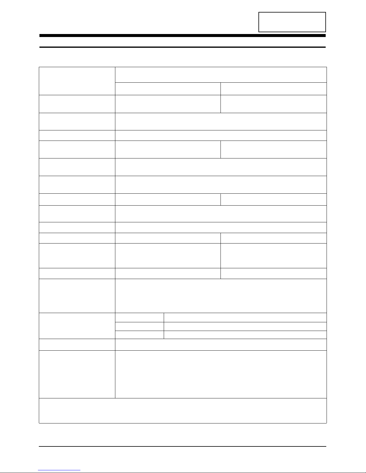
2-1 Specifications
LCD Panel
TFT-LCD panel, RGB vertical stripe, normally black TFT-LCD panel, RGB vertical stripe, normally black
transmissive, (21.3-Inch) viewable, 0.27 pixel pitch transmissive, (24.06-Inch) viewable, 0.27 pixel pitch
Scanning Frequency Horizontal : 30 kHz ~ 85 kHz (Analog)
Vertical : 55 Hz ~ 85 Hz
Display Colors 16,777,216 Million colors
Maximum Resolution Horizontal : 1600 Pixels 1920 Pixels
Vertical : 1200 Pixels 1200 Pixels
Input Video Signal Analog, 0.7 Vp-p ± 5% positive at 75 Ω,
internally terminated
Input Sync Signal Type : Seperate H/V sync, Composite H/V, Sync-on-Green
Level : TTL level
Maximum Pixel Clock rate 162 MHz 193 MHz
Active Display
Horizontal/Vertical
AC power voltage & Frequency AC 90 ~ 264 Volts, 60~50 Hz ± 3 Hz
Power Consumption 110W (max) 120W (max)
Dimensions
Unit (W x D x H)
25.98 x 8.38 x 18.58 Inches (568.5 x 213 x 472 mm)
25.98 x 8.38 x 18.58 Inches (660 x 213 x 472 mm)
Carton (W x D x H)
30.55 x 24.01 x 13.62 Inches (687 x 608 x 340 mm)
30.55 x 24.01 x 13.62 Inches (776 x 610 x 346 mm)
Weight (Net / Gross)
Environmental Considerations Operating Temperature : 50°F ~ 104°F (10°C ~ 40°C)
Humidity : 10 % ~ 80 %
Storage Temperature : -4°F ~ 113°F (-20°C ~ 45°C)
Humidity : 5 % ~ 95 %
TV System
Sound Characteristics •Max Internal speaker Out : Right c 5 W / Leftc 5 W
•Bass control Range : -6 ± 2dB ~ +6 ± 2dB
•TREBLE control Range : -10 ± 2dB ~ +10 ± 2dB
•Output frequency : RFc 80 Hz~15 KHz /A/Vc 80 Hz~20 KHz
•Line out : RFc 80 Hz~15 KHz /A/Vc 80 Hz~20 KHz
•SyncMaster RS21A*/RS24A* comply with SWEDAC (MPRII) recommendations for reduced electromagnetic fields.
•Designs and specifications are subject to change without prior notice.
RS21A*/RS24A* 2-1
Item
Description
RS21A*
RS24A*
518.4 ± 3 mm / 324 ± 3 mm
10.0 kg (26.78 lbs) / 20.2 kg ( 49.6 lbs) 12.15 kg (26.78 lbs) / 22.5 kg ( 49.6 lbs)
Antena Input 75Ω, Coaxial Cable
Tunning Frequency Synthesize
Color PAL, SECAM
Sound NICAM, A2 STEREO
CONFIDENTIAL
2 Product Specifications
2-2 RS21A*/RS24A*
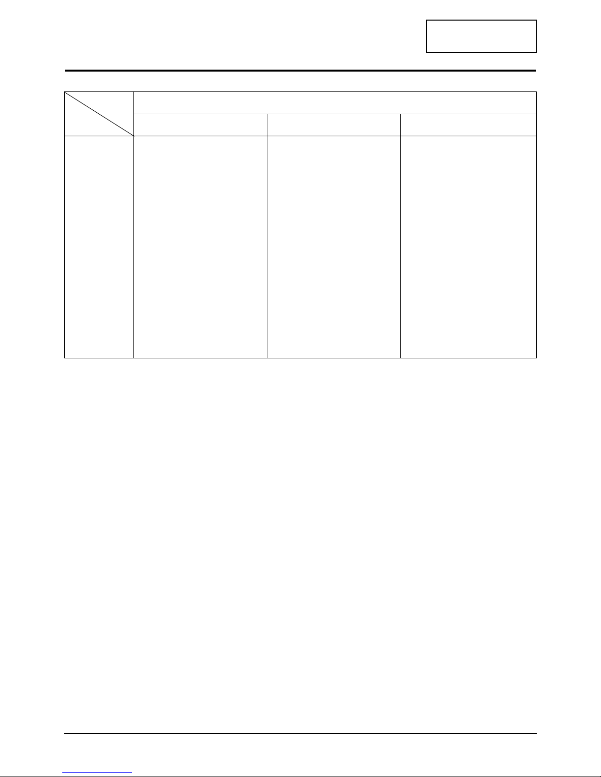
2-2 Pin Assignments
Sync
Type
Pin No.
15-Pin Signal Cable Connector
Separate Composite Sync-on-green
1
2
3
4
5
6
7
8
9
10
11
12
13
14
15
Red
Green
Blue
GND
GND (DDC Return)
GND-Red
GND-Green
GND-Blue
No Connection
GND-Sync./Self Test
GND
DDC Data
Horizontal sync.
Vertical sync.
DDC Clock
Red
Green
Blue
GND
GND (DDC Return)
GND-Red
GND-Green
GND-Blue
No Connection
GND-Sync./Self Test
GND
DDC Data
H/V-Sync.
Not Used
DDC Clock
Red
Green + H/V Sync.
Blue
GND
GND (DDC Return)
GND-Red
GND-Green
GND-Blue
Not Used
GND-Sync./Self Test
GND
DDC Data
Not Used
Not Used
DDC Clock
CONFIDENTIAL
2 Product Specifications
RS21A*/RS24A* 2-3
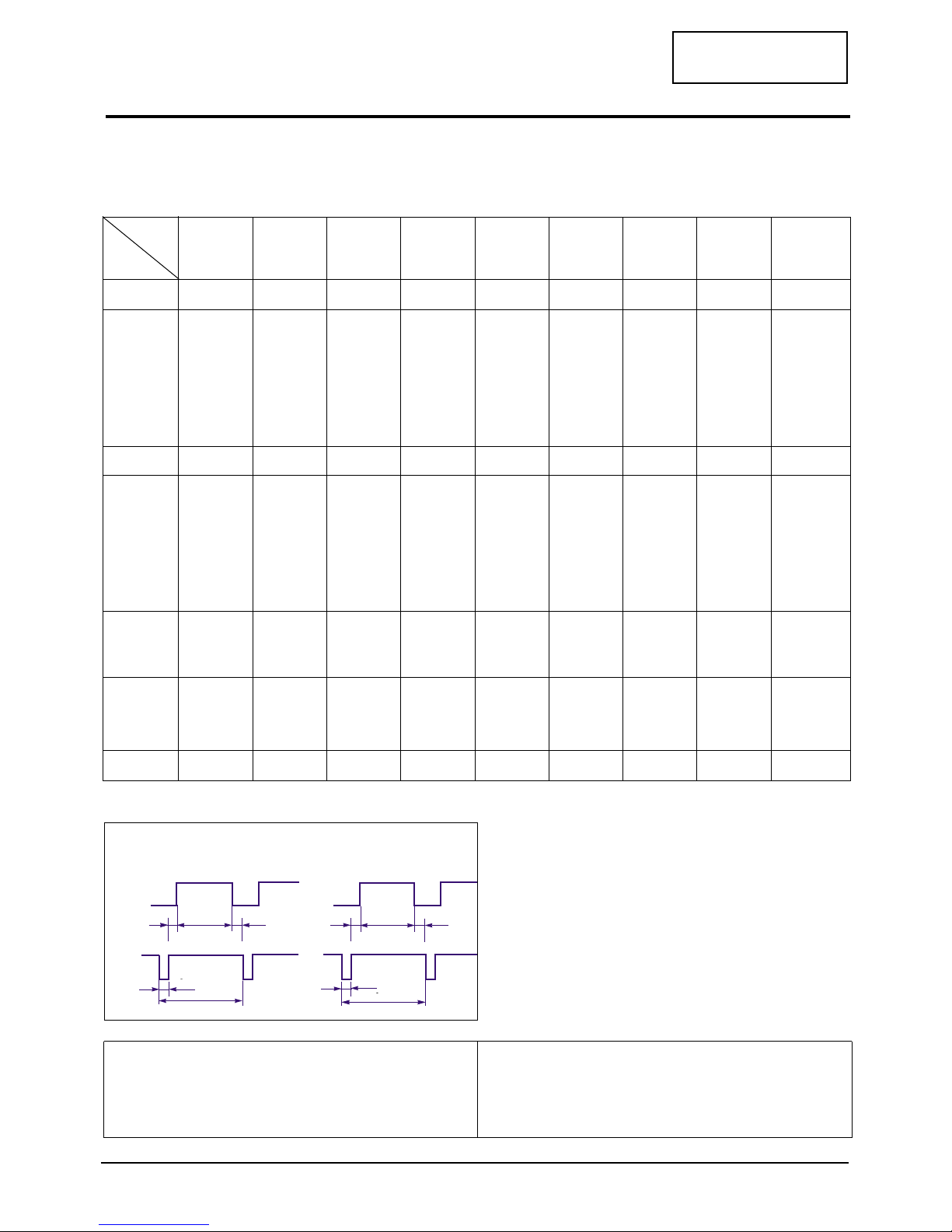
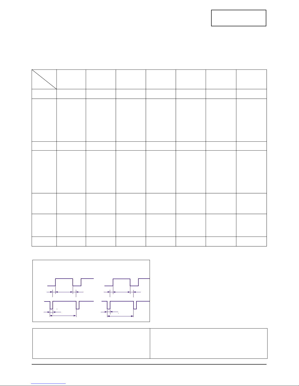
2-3 Timing Chart
This section of the service manual describes the timing that the computer industry recognizes as standard
for computer-generated video signals.
48.1
1040
120
64
800
56
72.2
666
6
23
600
37
50.000
Positive
Positive
Separate
37.9
1056
128
88
800
40
60.3
628
4
23
600
1
40.000
Positive
Positive
Separate
35.2
1024
72
128
800
24
56.3
625
2
22
600
1
36.000
–/+
–/+
Separate
SVGA/56 Hz
800 x 600
SVGA/60 Hz
800 x 600
SVGA/72 Hz
800 x 600
MAC/66 Hz
640 x 480
35.0
864
64
96
640
64
66.7
525
3
39
480
3
30.240
Negative
Negative
Separate
fH (kHz)
A µsec
B µsec
C µsec
D µsec
E µsec
fV (Hz)
O msec
P msec
Q msec
R msec
S msec
Clock
Freq.
(MHz)
Polarity
H.Sync
V.Sync
Remark
VGA3/60 Hz
640 x 480
VGA/72 Hz
640 x 480
VGA/75 Hz
640 x 480
VGA/85 Hz
640 x 480
MAC/60 Hz
640 x 480
Table 2-1 Timing Chart
31.5
800
96
40
640
8
60.0
525
2
25
480
2
25.175
Negative
Negative
Separate
37.9
832
40
120
640
16
72.8
520
3
20
480
1
31.500
Negative
Negative
Separate
37.5
840
64
120
640
16
75.0
500
3
16
480
1
31.500
Negative
Negative
Separate
43.3
832
56
80
640
56
85.0
509
3
25
480
1
36.000
Negative
Negative
Separate
31.5
800
96
48
640
16
60.0
525
2
33
480
10
25.175
Negative
Negative
Separate
Mode
Timing
QRS
P
O
Video
Sync
Sync
Horizontal
Vertical
CDE
P
O
B
A
Video
Sync
Sync
Separate Sync
C D
A
O
E
B
P
Video
Sync
Sync
Video
Q R S
A : Line time total B : Horizontal sync width O : Frame time total P : Vertical sync width
C : Back porch D : Active time Q : Back porch R : Active time
E : Front porch S : Front porch

CONFIDENTIAL
2 Product Specifications
2-4 RS21A*/RS24A*
68.7
1456
128
144
1152
32
75.1
915
3
39
870
3
100.000
Negative
Negative
Separate
67.5
1600
128
256
1152
64
75.0
900
3
32
864
1
108.000
Positive
Positive
Separate
60.2
1328
96
176
1024
32
74.9
804
3
30
768
3
80.000
Negative
Negative
Separate
MAC/74 Hz
1024 x 768
VESA/75 Hz
1152 x 864
MAC/75 Hz
1152 x 870
MAC/60 Hz
1024 x 768
48.8
1312
96
128
1024
64
60.0
813
6
33
768
6
64.000
Negative
Negative
Separate
46.9
1056
80
160
800
16
75.0
625
3
21
600
1
49.500
Positive
Positive
Separate
fH (kHz)
A µsec
B µsec
C µsec
D µsec
E µsec
fV (Hz)
O msec
P msec
Q msec
R msec
S msec
Clock
Freq.
(MHz)
Polarity
H.Sync
V.Sync
Remark
MAC/74 Hz
832 x 624
XGA/60 Hz
1024 x 768
XGA/70 Hz
1024 x 768
XGA/75 Hz
1024 x 768
XGA/85 Hz
1024 x 768
SVGA/75 Hz
800 x 600
SVGA/85 Hz
800 x 600
Table 2-2 Timing Chart (continued)
53.7
1048
64
152
800
32
85.1
631
3
27
600
1
56.250
Positive
Positive
Separate
49.7
1152
64
224
832
32
74.6
667
3
39
624
1
57.284
Negative
Negative
Separate
48.4
1344
136
160
1024
24
60.0
806
6
29
768
3
65.000
Negative
Negative
Separate
56.5
1328
136
144
1024
24
70.1
806
6
29
768
3
75.000
Negative
Negative
Separate
60.0
1312
96
176
1024
16
75.0
800
3
28
768
1
78.750
Positive
Positive
Separate
68.7
1376
96
208
1024
48
85.0
808
3
36
768
1
94.500
Positive
Positive
Separate
Mode
Timing
QRS
P
O
Video
Sync
Sync
Horizontal
Vertical
CDE
P
O
B
A
Video
Sync
Sync
Separate Sync
C D
A
O
E
B
P
Video
Sync
Sync
Video
Q R S
A : Line time total B : Horizontal sync width O : Frame time total P : Vertical sync width
C : Back porch D : Active time Q : Back porch R : Active time
E : Front porch S : Front porch
CONFIDENTIAL
2 Product Specifications
RS21A*/RS24A* 2-5
QRS
P
O
Video
Sync
Sync
Horizontal
Vertical
CDE
P
O
B
A
Video
Sync
Sync
Separate Sync
C D
A
O
E
B
P
Video
Sync
Sync
Video
Q R S
A : Line time total B : Horizontal sync width O : Frame time total P : Vertical sync width
C : Back porch D : Active time Q : Back porch R : Active time
E : Front porch S : Front porch
fH (kHz)
A µsec
B µsec
C µsec
D µsec
E µsec
fV (Hz)
O msec
P msec
Q msec
R msec
S msec
Clock
Frequency
(MHz)
Polarity
H.Sync
V.Sync
Remark
SUN/76 Hz
1280 x 1024
SXGA/60 Hz
1280 x 1024
SUN/76 Hz
1152 x 900
71.7
1472
96
208
1152
16
76.0
943
8
33
900
2
105.561
Negative
Negative
Separate
SUN/66 Hz
1152 x 900
61.8
1528
128
208
1152
40
66.0
937
4
31
900
2
94.500
–/+
–/+
Separate
64.0
1688
112
248
1280
48
60.0
1066
3
38
1024
1
108.000
Positive
Positive
Separate
74.4
1680
160
208
1280
32
70.0
1063
3
36
1024
0
125.000
Negative
Negative
Separate
80.0
1688
144
248
1280
16
75.0
1066
3
38
1024
1
135.000
Positive
Positive
Separate
81.1
1664
64
288
1280
32
76.1
1066
8
32
1024
2
135.000
Negative
Negative
Separate
SXGA/75 Hz
1280 x 1024
78.1
1728
192
192
1280
64
72.0
1085
3
55
1024
3
135.000
Negative
Negative
Separate
HP/72 Hz
1280 x 1024
NCD/70 Hz
1280 x 1024
Table 2-3 Timing Chart (continued)
Mode
Timing

CONFIDENTIAL
2 Product Specifications
2-6 RS21A*/RS24A*
QRS
P
O
Video
Sync
Sync
Horizontal
Vertical
CDE
P
O
B
A
Video
Sync
Sync
Separate Sync
C D
A
O
E
B
P
Video
Sync
Sync
Video
Q R S
A : Line time total B : Horizontal sync width O : Frame time total P : Vertical sync width
C : Back porch D : Active time Q : Back porch R : Active time
E : Front porch S : Front porch
Table 2-4 Timing Chart (continued)
fH (kHz)
A µsec
B µsec
C µsec
D µsec
E µsec
fV (Hz)
O msec
P msec
Q msec
R msec
S msec
Clock
Frequency
(MHz)
Polarity
H.Sync
V.Sync
Remark
UXGA/70Hz
1600 x 1200
UXGA/65Hz
1600 x 1200
81.25
2160
192
304
1600
64
65
1250
3
46
1200
1
175.500
–/+
–/+
Separate
UXGA/60Hz
1600 x 1200
75
2160
192
304
1600
64
60
1250
3
46
1200
1
162.000
–/+
–/+
Separate
87.5
2160
192
304
1600
64
70
1250
3
46
1200
1
189.000
–/+
–/+
Separate
80.038
2124
160
308
1600
56
64.443
1242
3
38
1200
1
170.000
–/+
–/+
Separate
74.52
2592
208
336
1920
128
60
1242
3
38
1200
1
193.156
Negative
Positive
Separate
WUXGA2/60 Hz
1920 x 1200
89.286
2240
256
368
1600
16
66.931
1334
10
44
1200
80
200.000
–/+
–/+
Separate
SUN/66 Hz
1600 x 1200
NCD/64Hz
1600 x 1200
Mode
Timing
3-1-1 Removing the Stand
1. Disconnect power cord and signal cable.
2. Remove 2 screws and bushing on the each
side of stand.
3-1-2 Main Body Disassembly
1. Remove the tuner-box.
2. Remove 3 cap-screw and screws on the Rear
Cover.
3. Remove Rear Cover from the Front Cover.
4. Remove 1 screw on the PCB and remove the
tuner-guide.
5. Remove 9 screws on the shield and remove
the shield.
6.
Disconnect Inverter wire, Function PCB wire,
Audio wire, Interface wire, and IR sensor wire .
Remove 6 screws on the main PCB and 4
screws on the Inverter PCB.
7. Remove the main PCB Assembly and Inverter
PCB.
8. Remove 4 screws on the Rear Panel Bracket.
9. Remove the Bracket Assembly from the Front
Cover.
10. Remove 4 screws on the panel and then
remove the panel.
11. Remove 8 screws on the Bracket Hinge.
12. Remove the Braket Hinge.
RS21A*/RS24A* 3-1
CONFIDENTIAL
3 Disassembly and Reassembly
This section of the service manual describes the disassembly and reassembly procedures for the
RS21A*/RS24A* monitor.
WARNING: This monitor contains electrostatically sensitive devices. Use caution when handling
these components.
3-1 Disassembly
Cautions:1. Disconnect the monitor from the power source before disassembly.
2. Follow these directions carefully; never use metal instruments to pry apart the cabinet.

CONFIDENTIAL
3 Disassembly and Reassembly
3-2 RS21A*/RS24A*
3-2 Replacement Order of Lamp Assemblies
1. Remove the lamp wire holding tape from
the metal chassis on the bottom side.
1-1. Taking out the lamp wire from
the lamp wire holder.
2. Unscrewing the screw.
Unscrewing force : 0.8 ~ 1Kg - f.cm
3. Pulling out the lamp Assembly with
stable Power and direction slowly.
Be careful, do not twist the lamp reflector
when pulling the lamp.

CONFIDENTIAL
3 Disassembly and Reassembly
RS21A*/RS24A* 3-3
3-3 Reassembly
Reassembly procedures are in the reverse order of Disassembly procedures.
* Replacement of lamp unit should be done at the power off state and rcommended clean bench
condition.
4. Dis-Assembled the lamp Ass’y from LCD
completely.

Memo
3 Disassembly and Reassembly
3-4 RS21A*/RS24A*
CONFIDENTIAL
CONFIDENTIAL
RS21A*/RS24A* 4-1
4 Alignments and Adjustments
This section of the service manual explains how to use the DDC JIG to adjust the black, red, green, and blue
levels of the FPD when you replace the AD Board, and how to update the microprocessor when you
change the Panel or Lamp(s).
4-1 General Alignment Instuction
1. Usually, a color TV-VCR needs only slight touch-up adjustment upon installation.
Check the basic characteristics such as height, horizontal and vertical sync.
2. Use the specified test equipment or its equivalent.
3. Correct impedance matching is essential.
4. Avoid overload. Excessive signal from a sweep generator might overload the front-end
of the TV. When inserting signal markers,do not allow the marker generator to distort
test result.
5. Connect the TV only to an DC power source with voltage and frequency as specified on
the backcover nameplate.
6. Do not attempt to connect or disconnect any wire while the TV is turned on. Make sure
that the power cord is disconnected before replacing any parts.
7. To protect aganist shock hazard,use an isolation transform.
4-2 Adjustment Procedures
Use the following procedures whenever you replace the AD Board, Panel, or one or both of the Lamps.
4-2-1 (a) Color Auto Adjustment
1. After displaying 16-Gray pattern of XGA mode press channel “+”, ”–”, and “menu” buttons.
2. During normal execution of Auto Algorithm the screen image may change. If Auto Algorithm does
not excute properly, try one more.
3. After normal execution of Auto Algorithm, confirm optimal settings by observing the contrast of
several different patterns on the display.
4-2-2 (b) White Balance Adjustment
1. After displaying white pattern (on the WUXGA mode), press channel “+”,”–” and “Exit” buttons.
2. During normal execution df white balance the screen, image may change.

Memo
4 Alignments and Adjustments
4-2 RS21A*/RS24A*
CONFIDENTIAL

CONFIDENTIAL
RS21A*/RS24A* 5-1
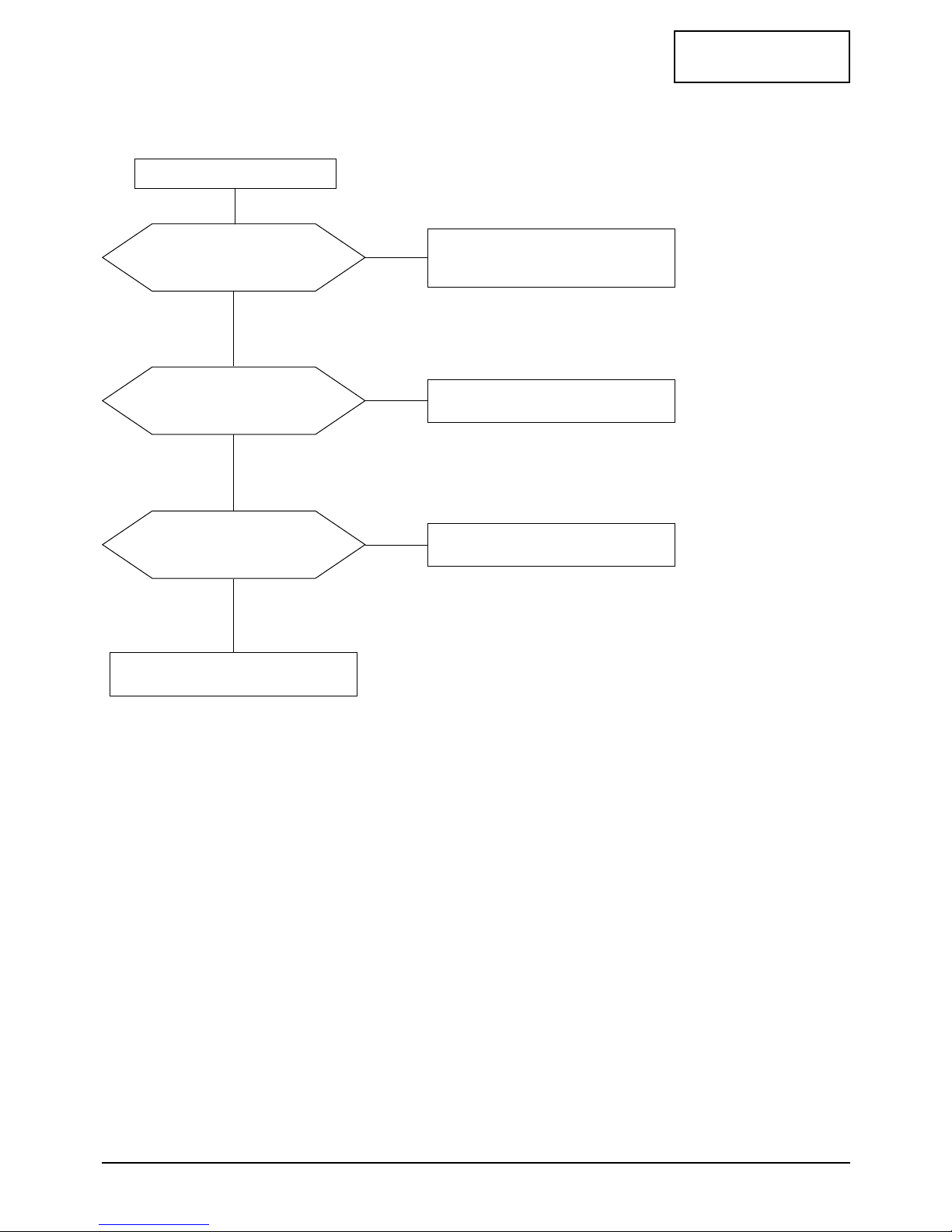
5 Troubleshooting
Does proper DC 14 V appear at
DC jack connected to CN800?
Check SMPS PCB and Adapter.
Yes
No
Does proper DC 5 V appear at
Pin 2 of IC815 and IC816?
Check IC815 and IC 816
Check IC811 and IC817.
Yes
No
Does proper DC 2.5 V appear at
Pin 2 of IC804 and IC806?
Check IC804 and IC806
.
Yes
No
Does proper DC 3.3 V appear at
Pin 2 of IC800, IC801 and IC805?
Check IC800, IC801 and IC805.
Yes
No
Does proper DC 5 V appear at
Pin 2 of IC810?
Check IC810.
Yes
No
5-1 No Power
CONFIDENTIAL
5 Troubleshooting
5-2 RS21A*/RS24A*
5-2 No Video (PC Analog Signal)
Power indicator is green
Does the signal appear at Pin 7,
15 and 22 of IC203, IC206?
Check R226, R228, R229,
C237, C238, C239, R246, R247,
R249, C258, C260, C262.
Yes
No
Does the clock pulse appear at
Pin 115 and 117 of IC203?
Check IC203 and related circuit of IC203.
Yes
No
Does the colck pluse
appear at Pin 8 of IC207?
Check related circuit of IC207.
Yes
No
Replace LCD Panel.

CONFIDENTIAL
5 Troubleshooting
RS21A*/RS24A* 5-3
5-3 No Picture (CVBS, S-VHS, Scart Video)
Check Pin 4 (5V_Tuner) of IC816
Pin 20 (Scart_Vin) of CN302.
Check CN301 (Tuner),
CN302 (Scart connector).
Yes
No
Check Pin 15
(RF_CVBS) of CN301.
Replace Tuner.
Yes
No
Check IC303 (VPC3230D).
Check related circuit of IC303
and replace IC303.
Yes
No
IC105 and IC106 and replace it.

CONFIDENTIAL
5 Troubleshooting
5-4 RS21A*/RS24A*
Does the Low signal at
Pin 9 and of IC101?
Check Pin 4 and 6 of CN102.
Yes
No
Check Pin 1 and 5 of IC101?
Replace IC101.
Yes
No
Check Pin 67 of
IC103 (MSP3451)?
Replace IC103 (MSP3451).
Yes
No
Check CN301 and tuner and
related circuit of CN301 and tuner.
5-4 No Sound
CONFIDENTIAL
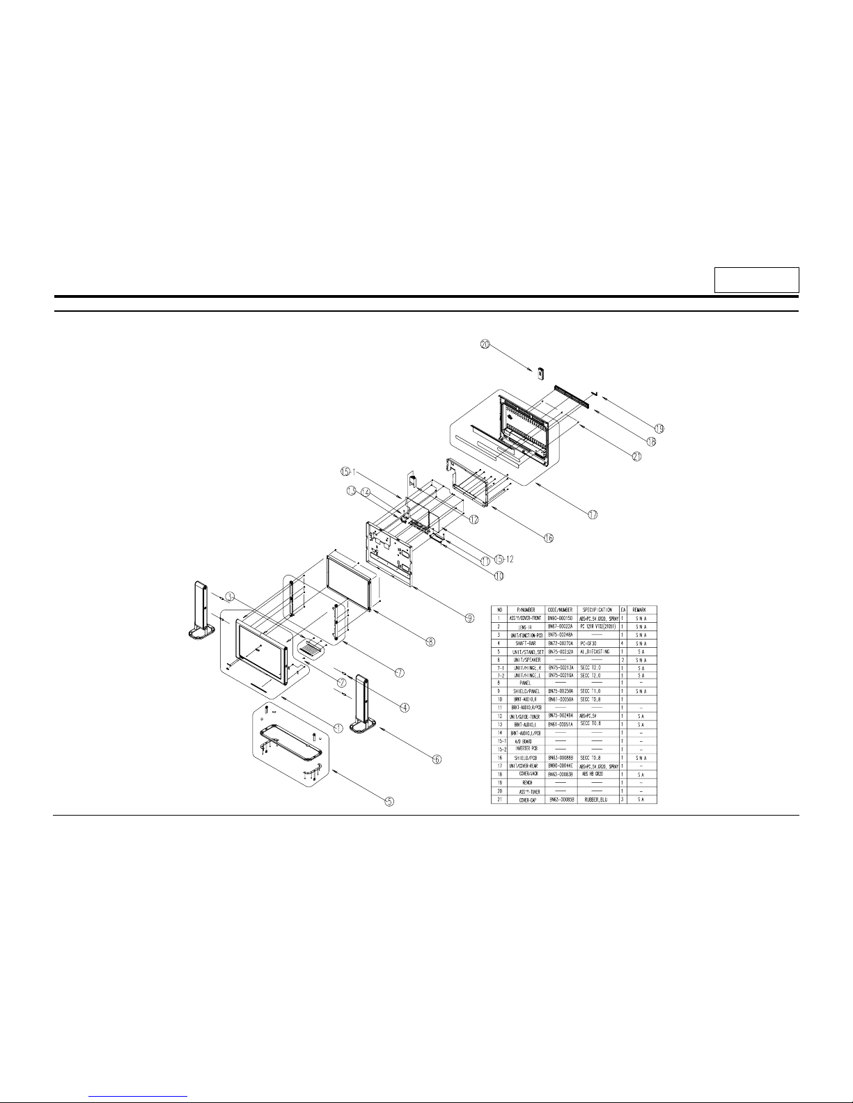
RS21A*/RS24A* 6-1
6 Exploded View and Parts List
6-1 RS21A*

6-2 RS24A*
6 Exploded View & Parts List
6-2 RS21A*/RS24A*
CONFIDENTIAL
 Loading...