

GANA-000029
Ed. 001
OfficeServ 12
Service Manual
COPYRIGHT
This manual is proprietary to SAMSUNG Electronics Co., Ltd. and is protecte d by copyri g ht.
No information contained herein may be copied, translated, transcribed or duplicated for any commercial
purposes or disclosed to third parties in any form without the prior written consent of SAMSUNG Electronics
Co., Ltd.
TRADEMARKS
is the trademark of SAMSUNG Electronics Co., Ltd.
Product names mentioned in this document may be trademarks and/or registered trademarks of their
respective companies.
This manual should be read and used as a guideline for properly installing and operating the product.
This manual may be changed for the system improvement, standardization and other technical reasons without prior
notice.
If you need updated manuals or have any questions concerning the cont ents of the manuals , contact our Document
Center at the following address or Web site:

Address: Document Center 2nd Floor IT Center. Dong-Suwon P.O. Box 105, 416, Maetan-3dong Yeongtong-gu,
Homepage: http://www.samsungdocs.com
©2004 SAMSUNG Electronics Co., Ltd. All rights reserved.
Suwon-si, Gyeonggi-do, Korea 442-600

INTRODUCTION
Purpose
This manual provides service information such as specifications, disassembly and
reassembly, troubleshooting, exploded view, parts list, H/W block diagram, schematic
description, and PCB Diagram of the OfficeServ 12 system.
Document Content and Organization
OfficeServ 12
This manual is composed of 5 chapters and annex and abbreviation as follows.
CHAPTER 1. System Specifications
This chapter introduces the hardware and specifications of the OfficeServ 12 system.
CHAPTER 2. Disassembly and Reassembly
This chapter describes how to disassemble the OfficeServ 12 system.
CHAPTER 3. Troubleshooting
This chapter describes problems that may occur while using the OfficeServ 12 system and
the solutions to such problems.
CHAPTER 4. H/W Block Diagrams and Schematic Description
This chapter describes the hardware block diagrams and provides a schematic description
of the OfficeServ 12 system.
CHAPTER 5. Exploded View and Parts List
This chapter describes the exploded view and parts list of the OfficeServ 12 system.
ANNEX A. PCB Component Layout
This annex describes the solder side and component side layout of the OfficeServ 1 2 s ystem.
ABBRIVATION
Describes the acronyms used in this manual.
© SAMSUNG Electronics Co., Ltd.
I
Conventions
The following types of paragraphs conta i n special i nformation that must be carefully read
and thoroughly understood. Such information may or may not be enclosed in a rectangular
box, separating it from the main text, but is always preceded by an icon and/or a bold title.
WARNING
Provides information or instructions that the reader should follow in order to avoid
personal injury or fatality.
CAUTION
Provides information or instructions that the reader should follow in order to avoid
a service failure or damage to the system.
CHECKPOINT
Provides the operator with checkpoints for stable system operation.
NOTE
Indicates additional information as a reference.
Reference
OfficeServ 12 Intallation Guide
This guide is an installer’s guide containing information on system specification, how to
install and set up the OfficeServ 12 system and how to connect the additional equipment.
Revision History
EDITION DATE OF ISSUE REMARKS
00 10. 2004. First Edition
01 05. 2005. The information about 4TRK Board is added.
© SAMSUNG Electronics Co., Ltd.
II
SAFETY CONCERNS
For product safety and correct operation, the following information must be given to the
operator/user and shall be read before the installation and operation.
Symbols
Caution
Indication of a general caution
OfficeServ 12
Restriction
Indica tion for pr ohi bi tin g an action for a product
Instruction
Indication for commanding a specifically required action
© SAMSUNG Electronics Co., Ltd.
III
Warning
Precautions for connecting door phone
- Do not directly connect the LOCK port of DPIM(Door Phone Interface Module)
to a commercial AC power supply to prevent fire and immediate breakdown of
the OfficeSe rv 12 sy stem.
- Connect a DPIM to a DLI port only after connecting a door pho ne to t he DPIM.
- The LOCK port of DPIM is standardized so tha t it i s used only for controlling
a low voltage relay. Standard values are 5 VDC and 40 mA.
Do not install the system in a location near a heat source such as a heater.
This is to prevent fire.
Precaution for cleaning
Do not spray directly on the unit, and do not clean the uni t with benzene, thinner
or alcohol to prevent fire and electric shock.
Do not wire the system during a lightning storm.
This is to prevent electric shocks caused by lightning.
Do not directly connect the external paging equipment or a common bell to
a commercial AC power supply.
This is to prevent fire and immediate breakdown of the OfficeServ 12 system.
Check whether the power is on before connecting a cable for battery connection.
Connecting the battery while the power is off may cause sparks, which can be
very dangerous.
Unplug the AC power cable before grounding the system.
Grounding the system while the AC power cable is plugged in may cause high
voltage, which can result in critical damage.
© SAMSUNG Electronics Co., Ltd.
IV
Cautions when repairing the product
- Unplug the power cable before repairing the product.
- Use standard parts for replacements.
- Do not turn off the power during program upgrades.
Follow the instructions below before disassembling the OfficeServ 12 system.
- Unplug the AC power cable and turn off the OfficeServ 12 system power.
- Remove the cables of external devices such as phone and external battery from
the OfficeServ 12 system.
- Wear wrist straps and ground the straps before handling boards or parts of the
OfficeServ 12 system.
© SAMSUNG Electronics Co., Ltd.
V
Caution
Caution for using battery
DC 48 V(6~40 AH) batteries should be used for OfficeServ 12. If the capacity of
the battery is too great, system malfunction m ay occur. I f the capacity is too small,
the system may not operate properly during a power failure.
Precaution for wall mounting
- If the wall is made of plaster or brick, or if the building is a prefabricated one,
you should place a 2 cm thi ck wood plate on the wall to prevent damaging the
wall.
- It may be difficult to drive a screw directly into a concrete wall. In such cases,
make a hole using an electric drill and insert a bushing into the hole first, and
then insert the screw into the bushing. This is to prevent the system from falling
and breaking.
Do not install the system places subje ct to moist ur e or wetness.
Do not install the system near a bathtub, wash-bowl, kitchen sink, and laund ry
tub, in a damp basement or near a swimming pool. Doing so may cause a
malfunction or shorten the life span of parts.
Do not disassemble, repair or modify at your discretion.
Contact your service center when repair is required.
Use only the power cable and battery indicated by this manual.
Use of an alternative power cable and battery may result in serious damage,
which will not be covered by the product warranty.
Connect the OfficeServ 12 system to an independent AC outlet.
Sharing AC power with other devices can cause noise or malfun ction du e to
voltage drop.
© SAMSUNG Electronics Co., Ltd.
VI

OfficeServ 12
TABLE OF CONTENTS
INTRODUCTION I
Purpose ..................................................... .................................................................. ................................I
Document Content and Organization.................................................. ................ .................... ........ ..........I
Conventions.............................................................. ............ ............ ............ ................ .. .............. ............ .II
Reference...................................................................................... ............ ............ ........ .... ............ ............ .II
Revision History........................................................................................ ............ ........... ......... ............ .....II
SAFETY CONCERNS III
Symbols..................................................................... ............ ............ ............ ............ ... ............. ............ ....III
Warning ................................ ......................................................... ............................................ ............ ....IV
Caution ..................................................................................................................................... ............ ....VI
CHAPTER 1. System Specifications 1
1.1 Hardware Descriptions .................................. ............................................................................. 1
1.1.1 Front View........................................................................................ ............ ............ ..... ....... .........1
1.1.2 Ports and Switch (After Removing Side Cover)............................................................. ............ .2
1.1.3 Bottom View............................................................. ................ ................ ................ ........ ............ .3
1.2 Specifications............................................................................................................................... 4
1.2.1 CPU, Memory, Switch......................................................... ............ ............ ................ .................4
1.2.2 System Capacity.......................................... ............ ............ ................ ............ ............ ...... ...... .....4
1.2.3 Power S pecifications............................................................................... .................... ........ .........5
1.2.4 Environment S pecifications............................................................. ............ ............ ............ .... .....5
1.2.5 Cable S pecifications............................................................ ............ ............ ............ ........... ..... .....5
1.2.6 Dimensions.............................................................................. ............ ................ .........................5
1.2.7 Others...................................... ............ ............. ............ ............ ................ ............ ...... ...... ............ .5
CHAPTER 2. Disassembly and Reassembly 1
2.1 Boards and PSU........................................................................................................................... 1
2.1.1 When 3/4TRK is Equipped ................................................................................. ............ ........... ..1
2.1.2 When 2BRI is Equipped.................................................. ............ ............ ................ ............ .... .....2
2.2 Disassembly Procedure.............................................................................................................. 3
© SAMSUNG Electronics Co., Ltd.
VII

CHAPTER 3. Troubleshooting 1
3.1 Power Failures ......................................................................................................................... .... 2
3.2 Base board Failures ....................................................................................................................4
3.3 SLI Failures................................................................................................................................... 5
3.4 DLI Failures .................................................................................................................................. 9
3.5 MISC Failures............................... ............................ ...................................................................11
3.6 Caller ID Failures ....................... ................................................................................................ 14
3.7 LAN Failures...............................................................................................................................15
3.8 3/4TRUNK Failures ....................................................................................................................16
3.9 2BRI Failures.............................................................................................................................. 19
3.10 MGI Failures .................................................... ........................................................ ...................21
CHAPTER 4. H/W Block Diagrams and Schematic Description 1
4.1 H/W Block Diagram...................................................................................................................... 1
4.2 Schematic Description................................................................................................................ 2
4.2.1 Power Supply Unit........................................................... ................ ................ ................ ........ .....2
4.2.2 Base board...................................... ................. ............ ............ ............ ............ .............................4
4.2.3 3/4TRK, 2BRI Board.................................... ............ ............ ................ ............ ............ ......... ... ...19
4.2.4 MGI Board............................................... ................. ................ ................ .................... .. .............22
4.2.5 Ring Generator............................................................................ ............ ................ ...................23
CHAPTER 5. Exploded View and Parts List 1
5.1 Exploded View................................ ... .. .. ... ..... .. .. ... .. ..... .. .. ... .... ... .. .. ... .... ... .. .. ... ..... .. .. ... .. ................ 1
5.2 Parts List.............................................. ... .... ... .. .. ... .... ... .. .. ..... .. ... .. ..... .. ... .. .. ..... .. ... .. .......................2
5.2.1 Base Board.......................................................................... ................ ............ ............ ... ......... .....2
5.2.2 3TRK Board (MPD Ty pe, With CID)............................................................................... ...........12
5.2.3 3TRK Board (PRS Ty pe, With CID)................................ ................ ................ .................... .......16
5.2.4 4TRK Board (MPD Ty pe, Without CID)...................................................... .................... ...........19
5.2.5 4TRK Board (PRS Ty pe, Without CID).......................................................... ................ ...........24
5.2.6 2BRI Board.................................................................. ................ .................... ............... . ...........28
5.2.7 MGI Board............................................... ................. ................ ................ .................... .. .............31
ANNEX A. PCB Component Layout 1
A.1 Base board ................................................................................................................................... 1
A.1.1 Component Side.......................................................... ................ ................ .................... .... .........1
A.1.2 Solder Side.................................................. ............. ............ ............ ................ ............ . ....... .........2
© SAMSUNG Electronics Co., Ltd.
VIII

A.2 3/4TRK Board............................................................................................................................... 3
A.2.1 Component Side.......................................................... ................ ................ .................... .... .........3
A.2.2 Solder Side.................................................. ............. ............ ............ ................ ............ . ....... .........4
A.3 2BRI Board ................................................................................................................................... 5
A.3.1 Component Side.......................................................... ................ ................ .................... .... .........5
A.3.2 Solder Side.................................................. ............. ............ ............ ................ ............ . ....... .........6
A.4 MGI Board................................ ... .. .. ..... ... .. .. ..... .. ... .. .. ..... .. ... .. .. ..... .. ... .. .. ..... ... .. .. ..... .. ... .. ................ 7
A.4.1 Component Side.......................................................... ................ ................ .................... .... .........7
A.4.2 Solder Side.................................................. ............. ............ ............ ................ ............ . ....... .........7
ABBREVIATION I
A ~ D ................................................................................. ................ ................ ........ ............ ............ ......I
F ~ M ........................................ ............. ............ ................ ............ ............ ............ .... ............ ............ .....II
N ~ S ..................................................................... ............ ............ ............ ............................................III
T ~ W ........................................ ............. ............ ............ ................ ............ ............ .... ........ ............ ........IV
© SAMSUNG Electronics Co., Ltd.
IX

LIST OF FIGURES
Figure 1.1 Front View of the OfficeServ 12........................................................................... ......... ........1
Figure 1.2 Ports and Switch of the OfficeServ 12................................................................ ............ .. ...2
Figure 1.3 Bottom View of the OfficeServ 12............................................................... ............ ........ .....3
Figure 2.1 OfficeServ 12 Board Configuration (When 3/4TRK is Equipped).......................................1
Figure 2.2 OfficeServ 12 Board Configuration (When 2BRI is Equipped)...........................................2
Figure 4.1 H/W Block Diagram.............................................................................. ................ .... .............1
Figure 4.2 Power Supply System.................................................................. ............ ............ ........ .........2
Figure 4.3 Base board Block Diagram.................................................. ............ ................ ............ .... .....4
Figure 4.4 /TA (/DTACK) Signal Control........................................................ ................ ............ .... .........6
Figure 4.5 Engine (STC9604) Interface......................................................................................... ........8
Figure 4.6 Highway Allocation Block Diagram.................................. ............ ................ ............ ......... ....9
Figure 4.7 Reset Circuit Block Diagram........................................................ ............ ................ .... .......10
Figure 4.8 DLI Port Wiring Diagram...................................................... ............ ............ ............ .... .......15
Figure 4.9 Hybrid Port Wiring Diagram......................................................... ............ ................ .... .......16
Figure 4.10 SLI Port Wiring Diagram.................................................................... ............ ........... ..... ...16
Figure 4.11 Music Source/Paging/Dry Contact Wiring Diagram ........................................................17
Figure 4.12 Battery Backup........................................................... ................ ............ ............ . ........... ...18
Figure 4.13 Analog Trunk Board (3/4TRK)................................................... ................ .................... ...19
Figure 4.14 2BRI Block Diagram........................................................... .................... ................ .... .......21
Figure 4.15 MGI Block Diagram.................................................................................... ............ .... .......22
Figure 5.1 Exploded View of OfficeServ 12.................................................................................. .... .....1
LIST OF TABLES
Table 1.1 Front/Side Cover........................................................ ............ ............ ................ .... ........ .........1
Table 1.2 Ports and Switch Descriptions....................................................................................... ........ .2
Table 1.3 Bottom View Descriptions.............................................................................................. .........3
Table 1.4 CPU, Memory, Switch............................................................................................................ .4
Table 1.5 System Capacity .................................................................................................................... .4
Table 1.6 Power Specifications...............................................................................................................5
Table 1.7 Environment Specifications ....................................................................................................5
Table 1.8 Cable Specifications................................................................................................................5
Table 1.9 Dimensions..............................................................................................................................5
Table 1.10 Other Specifications..................................................................... ............ .............. .. ............ .5
© SAMSUNG Electronics Co., Ltd.
X
System Specifications
This chapter introduces the hardware and specifications of the OfficeServ 12 system.
Compliance with local standards
OfficeServ 12 is designed to comply w ith the s tandard of the corresponding country.
1.1 Hardware Descriptions
OfficeServ 12
This section introduces each view and part descriptions of the OfficeServ 12 system.
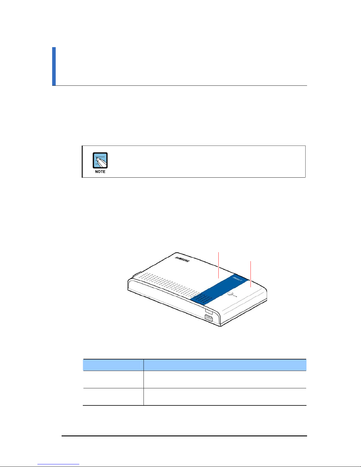
1.1.1 Front View
Item Description
Front Cover The front cover must be removed to view the boards or internal cables
Side Cover The side cover must be removed to view the ports and switc h es of the
Front cover
Figure 1.1 Front View of the OfficeServ 12
Table 1.1 Front/Side Cover
of the system or to disassemble the system.
system.
Side cover
© SAMSUNG Electronics Co., Ltd.
1
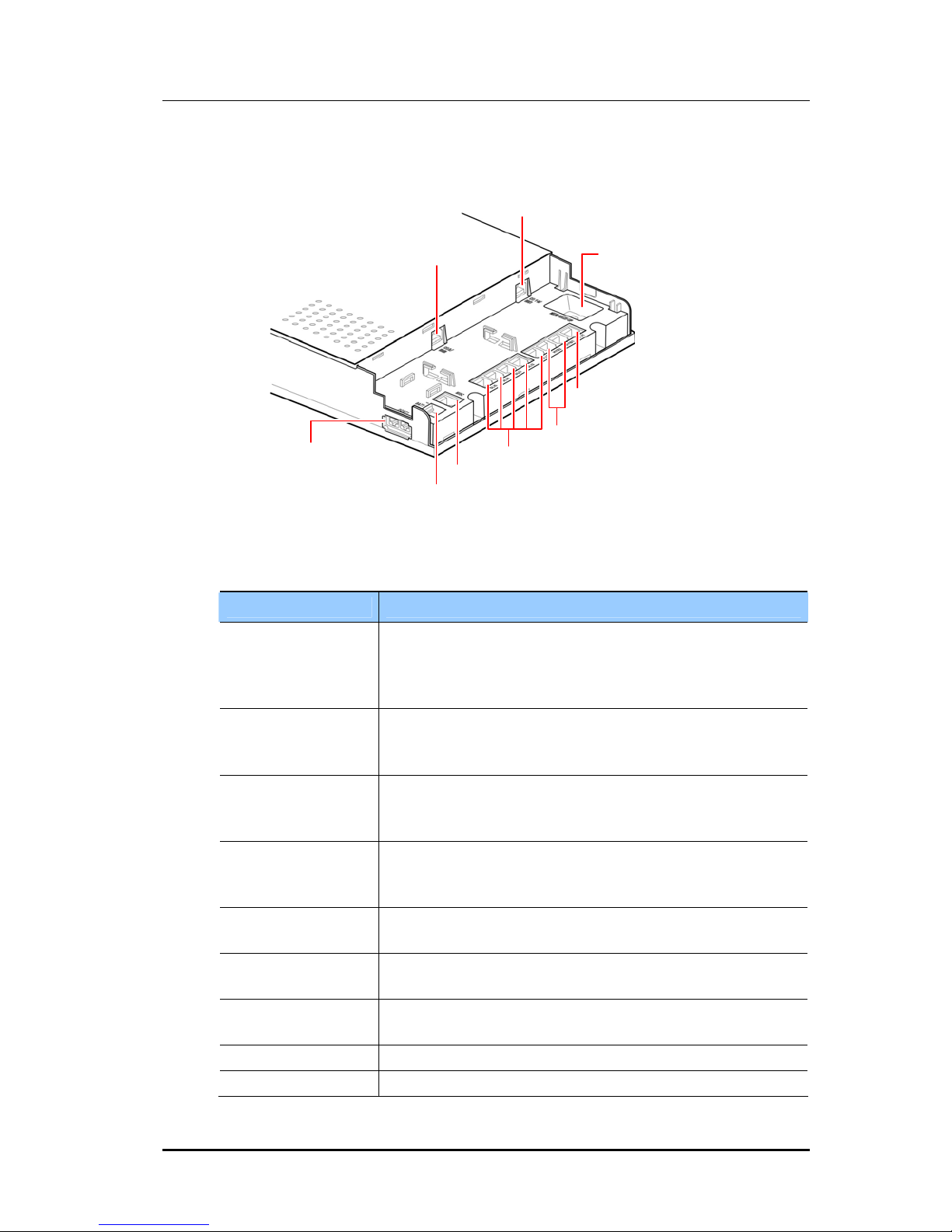
1.1.2 Ports and Switch (After Removing Side Cover)
CO1, 2/BRI1 port
Memory backup switch
DLI1 port
HYB1, HYB2 port
LAN port(for Hub/AP)
CO3, 4/BRI2 port
SLI1~SLI5 port
MISC port(General-purpose dry contact/external
Battery port
page/external music so urce port)
Figure 1.2 Ports and Switch of the OfficeServ 12
Table 1.2 Ports and Switch Descriptions
Item Description
CO3, 4/BRI2 port When the 2BRI(Basic Rate Interface) board is inst al led in the sy stem,
this port is for BRI2 port. When the 3TRK board is installed in the
system, this p ort is for CO(C entral Office ) 3 port only. When the 4TRK
board is installed in the system, this port is for CO3 or CO4 port.
CO1,2/BRI1 port When the 2BRI board is installed in the system, this port i s for BRI1
port. When the 3/4TRK board is installed in the system, this port is for
CO1 or CO2 port.
Memory backup
switch
This switch is for using the battery and supplying the power to the
OfficeServ 12 system when power is interrupted to keep data for a
predetermined time. The switch must be turned ‘ON’ after the data is input.
DLI1 port DLI1(Digital Line Interface 1) port is for connecti ng a digital phone
exclusively used for the OfficeServ 12 system to which the phone is
interlocked.
HYB1, HYB2 port HYB1(Hybrid1), HYB2(Hybrid2) ports are for connecting a digital
phone or analog phone.
SLI1~SLI5 port SLI(Single Line Interface) port is for connecting an analo g phone
generally used at home or office.
MISC port MISC(Miscellaneous) port is for connecting an external paging device.
MOH(Music On Hold), general purpose dry contact.
Battery port Battery port is for connecting a backup battery.
LAN port LAN(Local Area Network) port is for connecting a hub or AP(Access Point).
© SAMSUNG Electronics Co., Ltd.
2
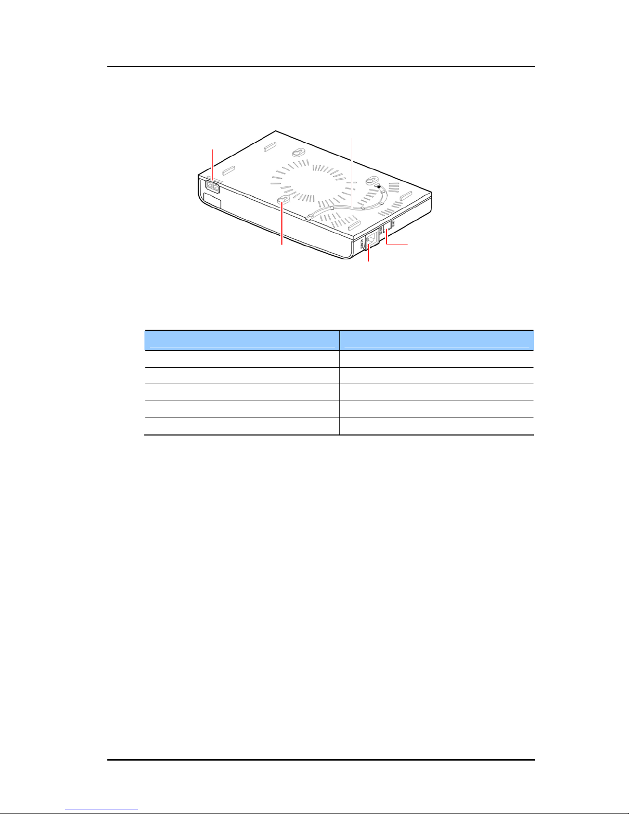
1.1.3 Bottom View
Groove for ground connection cable
LAN port
Groove for wall mounting
Figure 1.3 Bottom View of the OfficeServ 12
Table 1.3 Bottom View Descriptions
Item Description
Power connector
Power switch
Groove for ground connection cable A groove for grounding.
Power switch A switch for turning On/Off the AC power.
Power connector A port for connecting the power adaptor plug.
Groove for wall mounting A groove for wall mounting.
LAN port A port for connecting a hub or AP.
© SAMSUNG Electronics Co., Ltd.
3
1.2 Specifications
The specifications of the OfficeServ 12 system are as follows:
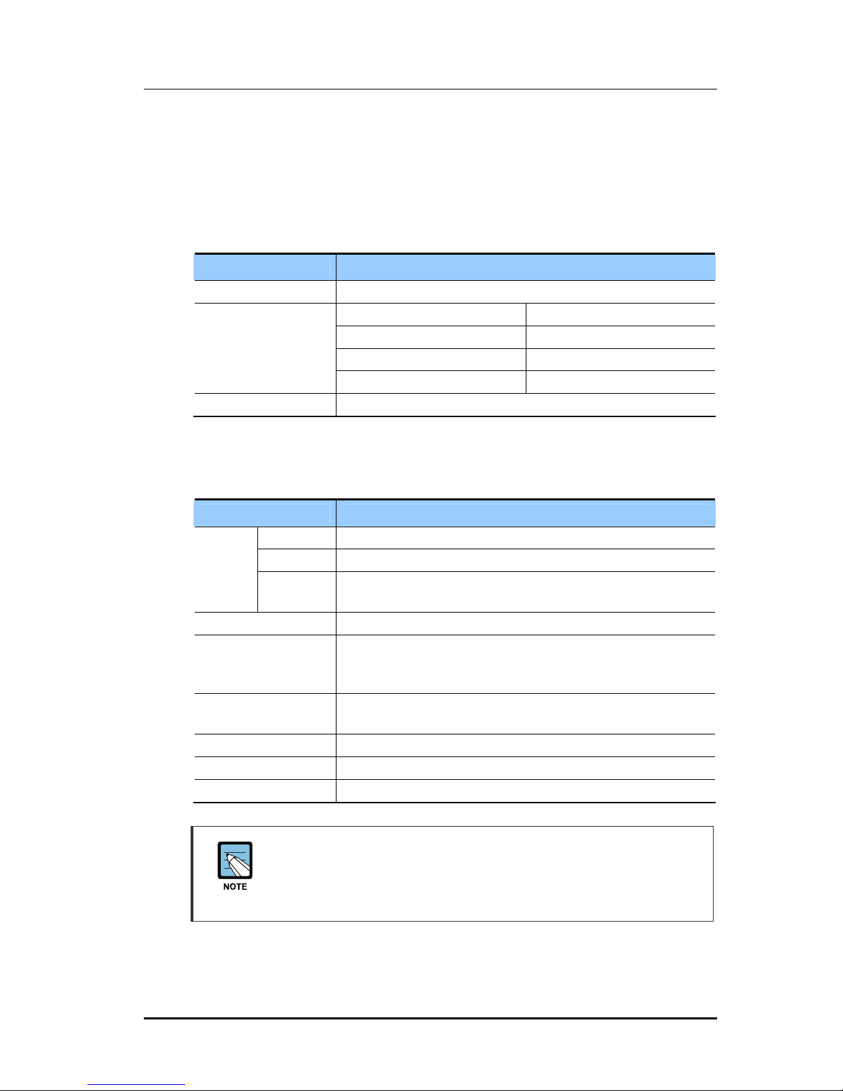
1.2.1 CPU, Memory, Switch
Table 1.4 CPU, Memory, Switch
Item Specification
CPU MPC855T
Memory
Switch Stru cture 256 × 256 T ime Slot
1.2.2 System Capacity
Boot ROM 512 KB
Flash ROM 8 MB
SRAM 2 MB
SDRAM 64 MB
Table 1.5 System Capacity
Item Specification
Trunk
Station 8 lines(1 line for digital phone, 2 hybrid, and 5 lines for analog phones)
Music-on-hold/
Background music
channel
General-purpose
dry contact
External Page 1
AP(for WLAN) 1
WIP-5000M phone 4
3TRK 3 Analog trunk lines(with Caller ID)
4TRK 4 Analog trunk lines(with Caller ID)
2BRI 2 Digital trunk lines(4 channels)(CO3/BRI2 line(2 Channels) can be
substituted for ISDN station lines)
1(internal or external)
1
The OfficeServ 12 system provides 8 s tation lines(1 DLI port, 2 HYB ports,
and 5 SLI ports).
DLI port supports 2B(KDB-D, KDB-S) and hybrid port supports analog phone and
digital phone(DLI max configuration: 3 ports, SLI max configuration: 7 ports).
© SAMSUNG Electronics Co., Ltd.
4
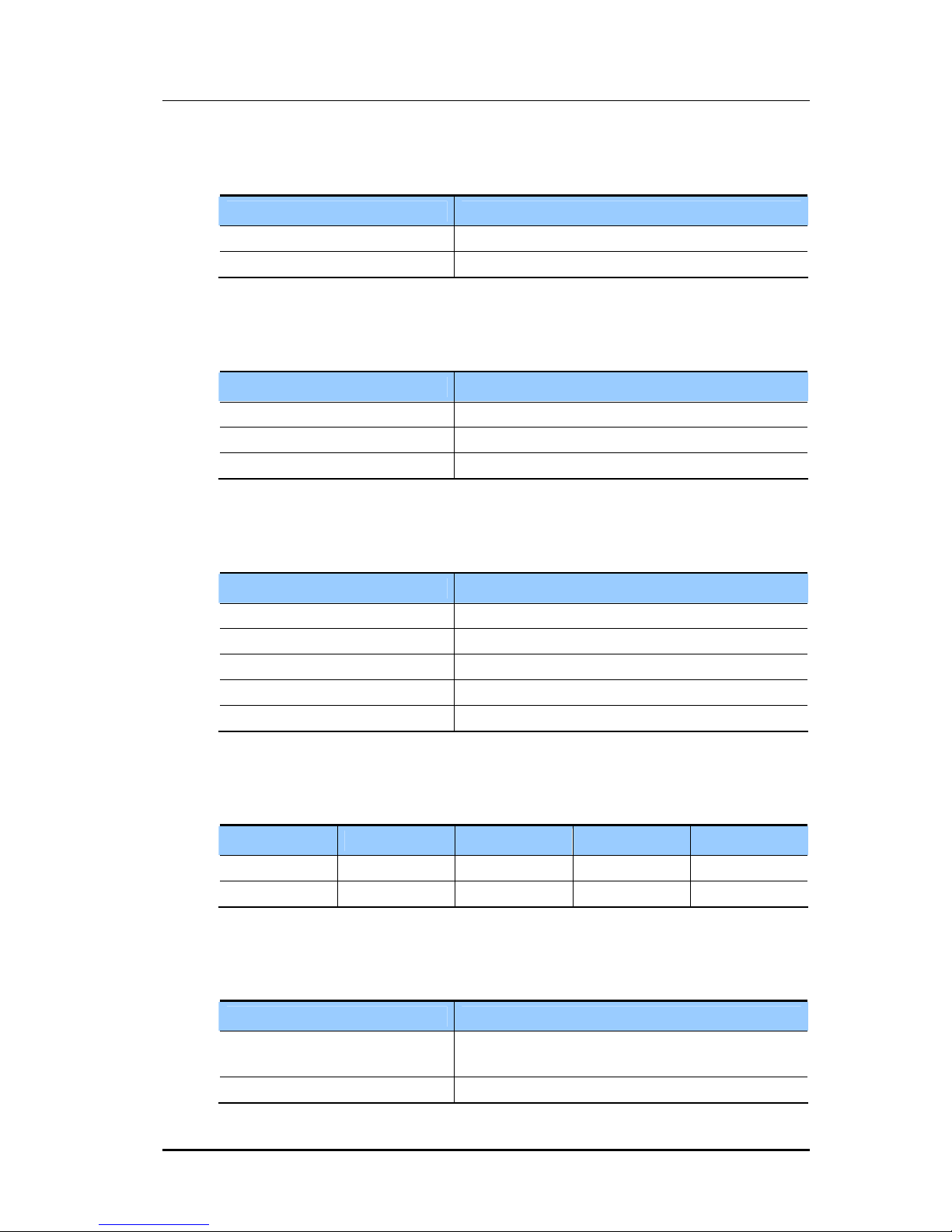
1.2.3 Power Specifications
Table 1.6 Power Specifications
Item Specification
AC Input 220~240 VAC, 50 Hz, 1.6 A
Maximum Power Consumption 55 Watts
1.2.4 Environment Specifications
Table 1.7 Environment Specifications
Item Specification
Operating Temperature 0~40 °C(32~104 °F)
Relative Humidity 10~90 %
Temperature(Storage) -10~50 °C(14~122 °F)
1.2.5 Cable Specifications
Item Specification
Digital Phone 2-line cable, maximum 400 m(1300 Ft)(AWG #24)
Analog Phone 2-line cable, maximum 1 km(3000 Ft)(AWG #24)
DPIM 2-line cable, maximum 300 m(1000 Ft)(AWG #24)
Door Phone 2-line cable, maximum 100 m(330 Ft)(AWG #24)
LAN RJ-45
1.2.6 Dimensions
Item Height(mm) Width(mm) Depth(mm) Mass(kg)
OfficeServ 12 190 350 60 2.0
DPIM 29 90 120 0.2
1.2.7 Others
Table 1.8 Cable Specifications
Table 1.9 Dimensions
Table 1.10 Other Specifications
External music source input
characteristics
External Page Impedance: 600 ohm
© SAMSUNG Electronics Co., Ltd.
Item Specification
Impedance: 600 ohm
Voltage: Maximum 350 mV
5

This page is intentionally left blank.
© SAMSUNG Electronics Co., Ltd.
6
Disassembly and Reassembly
This chapter introduces how to disassemble the OfficeServ 12 system.
You can reassemble the OfficeServ 12 system by following the steps in reverse order.
2.1 Boards and PSU
OfficeServ 12 is composed of the base board, 3/4TRK board, 2BRI board, MGI(Media
Gateway Interface) board, and PSU(Power Sup ply Unit).
OfficeServ 12
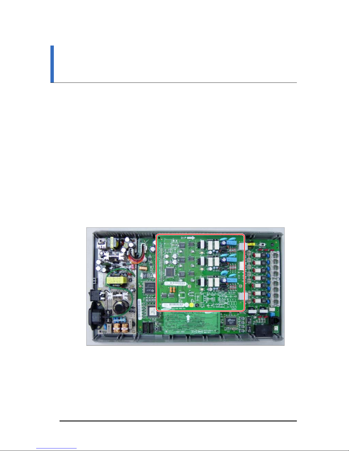
2.1.1 When 3/4TRK is Equipped
The following figure shows the board configuration of OfficeServ 12 when the 3/4TRK
analog trunk daughter board is equipped on the base board:
Figure 2.1 OfficeServ 12 Board Configuration (When 3/4TRK is Equipped)
© SAMSUNG Electronics Co., Ltd.
1
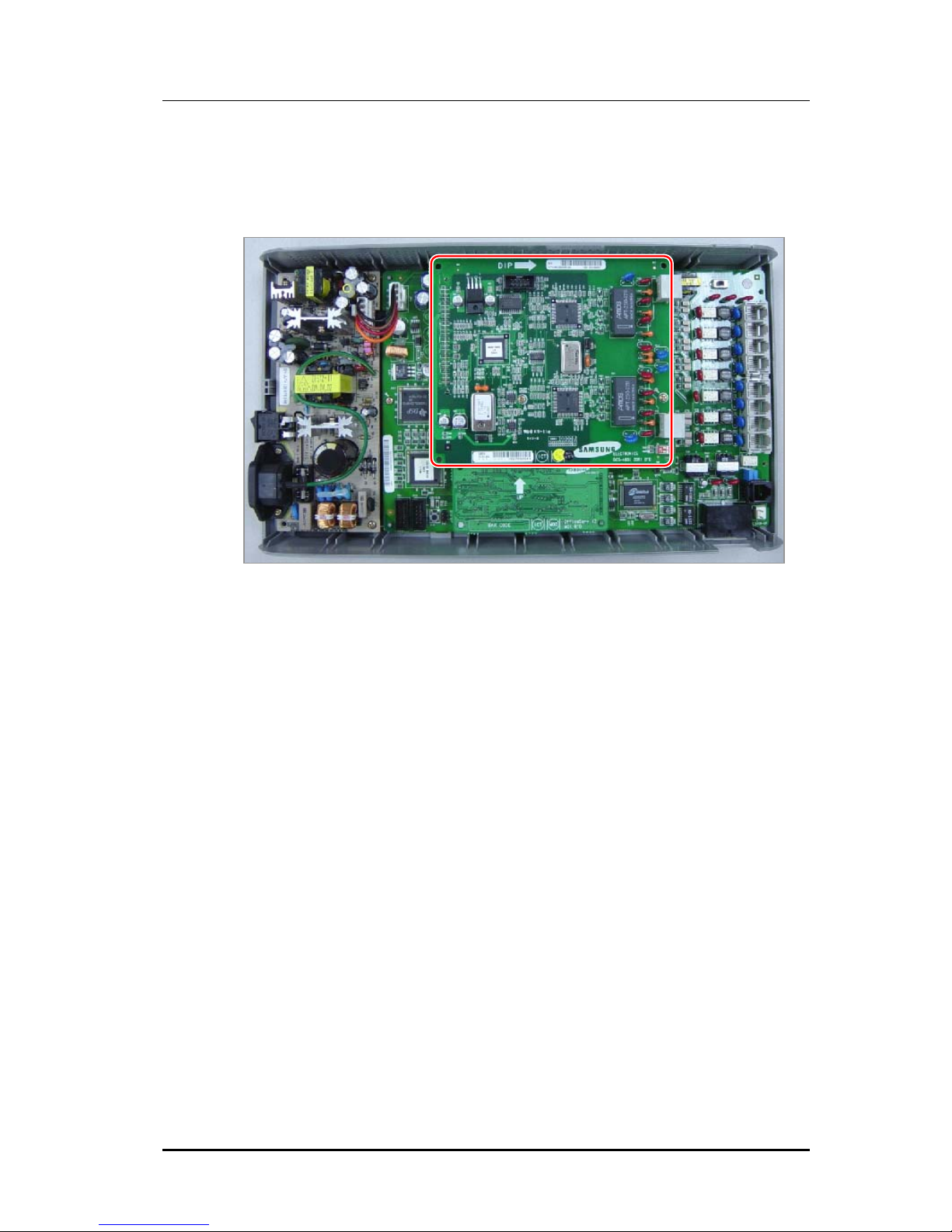
2.1.2 When 2BRI is Equipped
The following figure shows the board configuration of OfficeServ 12 when the 2BRI
digital trunk daughter board is equipped on the base board:
Figure 2.2 OfficeServ 12 Board Configuration (When 2BRI is Equipped)
© SAMSUNG Electronics Co., Ltd.
2
2.2 Disassembly Procedure
This section introduces how to disassemble the OfficeServ 12 system.
Reassembly
You can reassemble the Offi ceSe rv 12 sy stem in the re ve rse d pro cedu re of the
disassembly.
Disassemble the OfficeServ 12 system as following procedure.
Follow the instructions below before disassembling the OfficeServ 12 system.
- Unplug the AC power plug from the wall outlet and turn the OfficeServ 12
system power switch off.
- Remove the cables of external devices such as phone and external battery from
the OfficeServ 12 system.
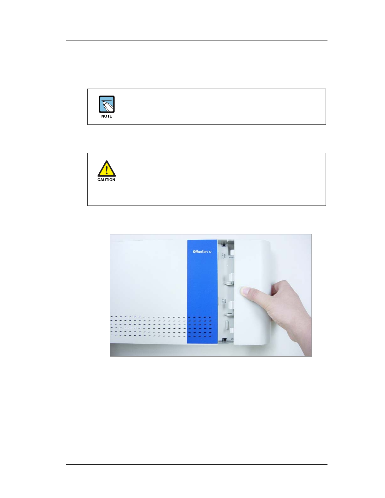
1) Remove the side cover by slightly pushing and pulling the upper part of the side cover.
© SAMSUNG Electronics Co., Ltd.
3
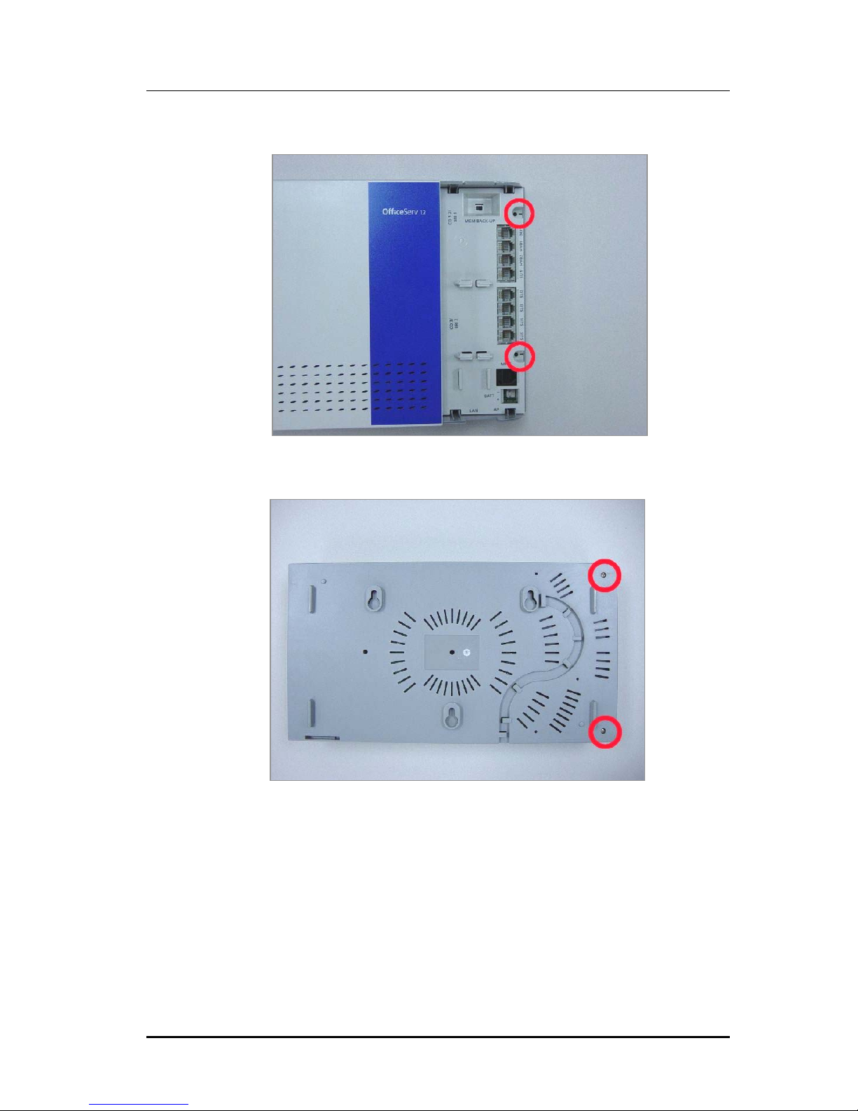
2) Remove the two screws at the side of the system.
3) Remove the two screws at the bottom panel of the system.
© SAMSUNG Electronics Co., Ltd.
4
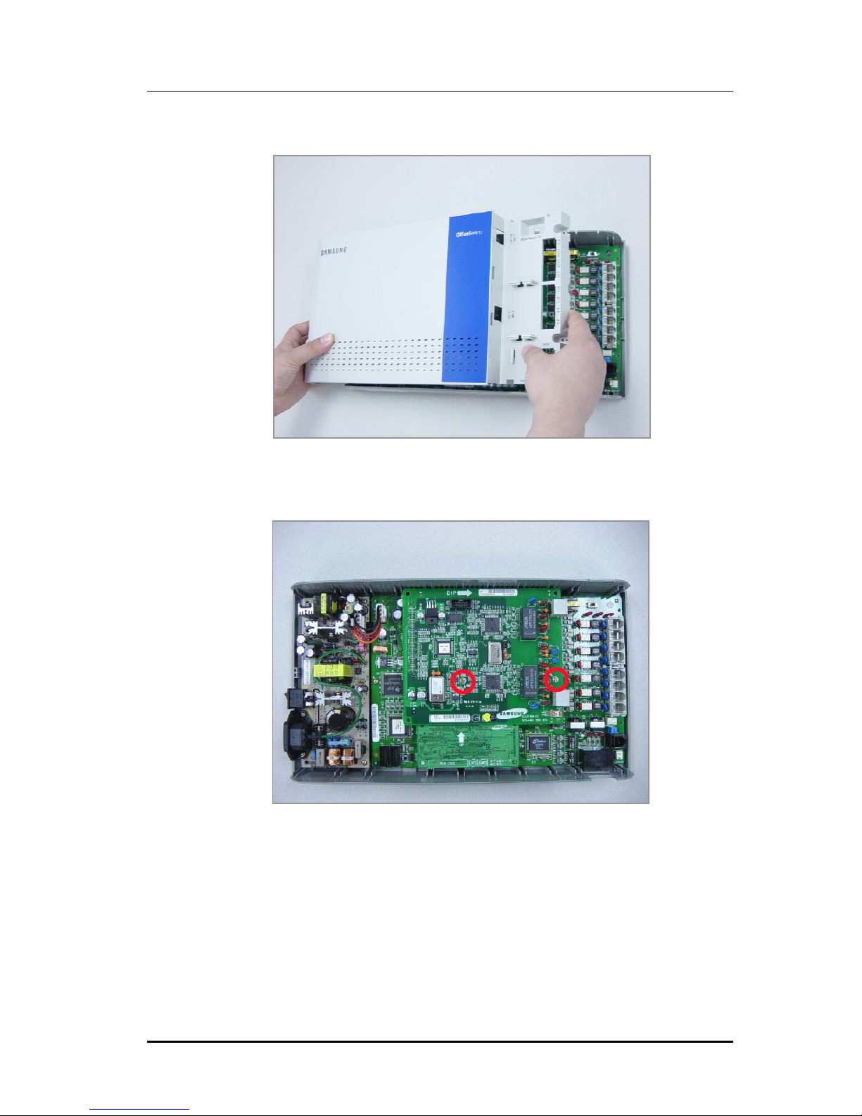
4) Remove the top cover.
5) Remove the two screws marked below in order to separate the 3/4TRK board or 2BRI
board:
© SAMSUNG Electronics Co., Ltd.
5
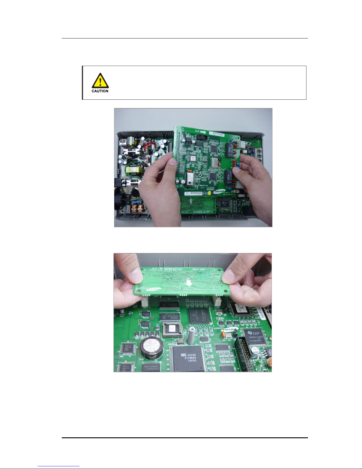
6) Remove the 3/4TRK board or 2BRI board from the base board.
Follow the instructions below before disassembling the OfficeServ 12 system.
Wear wrist straps and gro und the st raps before handling boards or parts of the
OfficeServ 12 system.
7) Remove the MGI board attached to the connectors on both ends of the base board.
© SAMSUNG Electronics Co., Ltd.
6
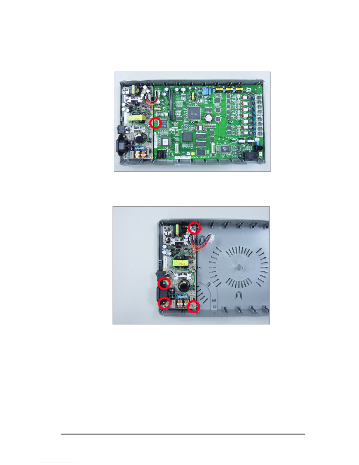
8) Remove the screw marked below to separate the base board from the system chassis:
Remove the cable from the PSU(Power Supply Unit).
9) Remove the 4 screws marked below to separate the PSU.
© SAMSUNG Electronics Co., Ltd.
7
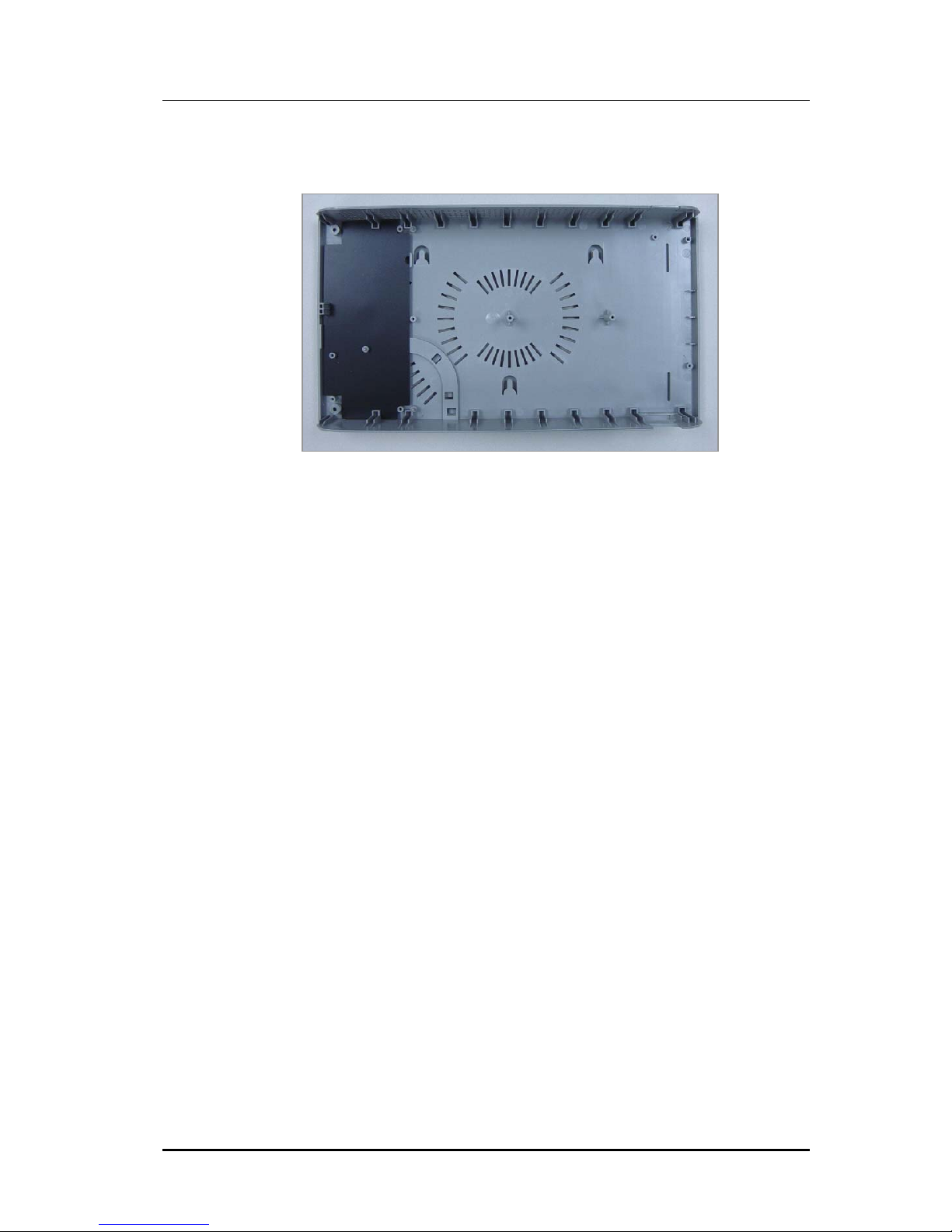
10) The system chassis should be emptied as shown below when all boards and PSU are
removed:
© SAMSUNG Electronics Co., Ltd.
8

Troubleshooting
This chapter describes problems that may occur while using the OfficeServ 12 system and
solutions for solving those problems.
OfficeServ 12
© SAMSUNG Electronics Co., Ltd.
1

3.1 Power Failures
Failure
The OfficeServ 12 system is not powered properly.
Troubleshooting
1) Check the Power supply as follows:
Turn on Power.
Is LED1(base board)
ON?
Yes
Yes
Is LED1(Base board)
blinking?
No
Check +5 V normal
Measure the voltage
between GND and +5V of P992.
Measure the voltage of P991.
Is the voltage
between 51 V and 57 V
measured?
A
Pull out the Power cable
No
connected to base board.
Measured the DC Voltage
between GND and -55 V
of CN21 within the power
board.
Is -55 V normal?
Yes
No
Check battery Fuse(F21)
within the power board.
No
Check the Fuse(F22) within
the power board.
A
Is F22 normal?
Yes
Replace the power board.
No
Replace the Fuse(F22)
- F22: 125 V, 2A.
Yes
END
© SAMSUNG Electronics Co., Ltd.
2
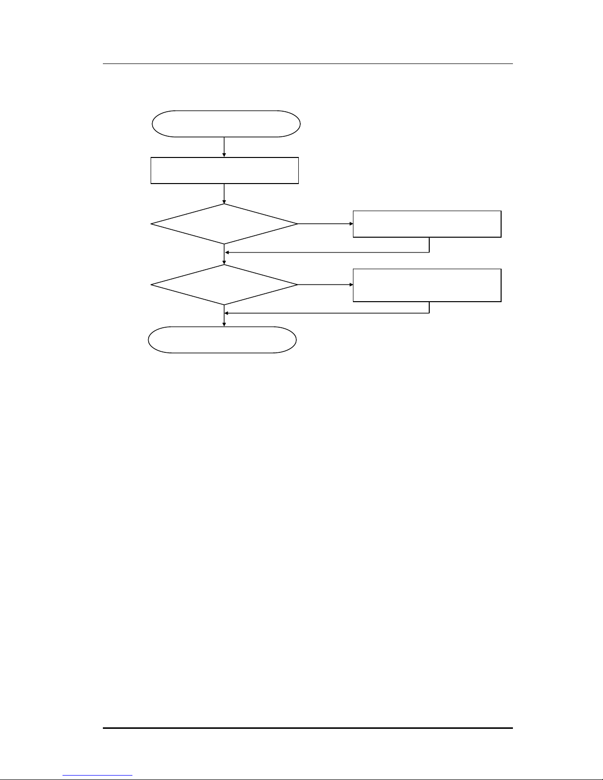
2) Check the poor battery backup as follows:
Analyze system battery.
Check the voltage of battery.
Is the value above 50 V?
No
Is the value under
45 V?
No
END
Yes
Yes
Usable without any restrictions.
The system will not work if battery is
Connected without AC power.
© SAMSUNG Electronics Co., Ltd.
3
 Loading...