


Samsung NP R40 Firenze II, NP-R40 Trouble Shooting

- This document cannot be used without the authorization of Samsung -
5. Troubleshooting
1) General
(1) Tools used for repairing the product
System Diagnostics Disk
MS-DOS Booting Disk
System Diagnostics Card
Screwdrivers (┼,━)
Tweezers
Multi-meter
Oscilloscope
Logic Analyzer
(2) Replaceable Units (FRU: Field Replaceable Unit)
DDR2 RAM Module
2.5” SATA HDD
ODD – Super multi Dual layer drive or DVD Combo Drive or Etc.
Wireless LAN Module
Bluetooth Module
MDC Module
Keyboard
System Fan
Touch Pad
LCD Panel
LCD Inverter
Main Board
PCMCIA Frame
Harness Cable – MDC Cable, Bluetooth Cable, LCD Cable,
Wireless LAN Antenna
FFC - Touch Pad FFC
5- 1
- This document cannot be used without the authorization of Samsung -
5. Troubleshooting
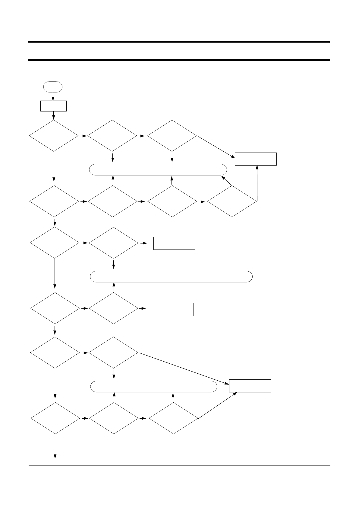
2) Debugging Flow Chart
Start
Power on
Power on?
YES
LCD display is OK ?
YES
Keyboard function is OK?
YES
HDD and ODD
recognition is OK
in CMOS ?
Check Adapter and
Battery.
Solution : Replace the defected part or revise the connectivity..
NO
Check RAM and
replace it.
NO
Check Keyboard
connection and
replace it.
NO
Check the connection
and change the unit.
No problem
It is
problem.
It is
problem.
No problem
No problem
It is
problem.
Solution : Replace the defected part or revise the connectivity..
It is
problem.
No problem
Check there is
any short in the
main board.
It is
problem.
It is
problem.
Check LCD cable.
Change Mainboard
and check it.
Change Mainboard
and check it.
No problem
No problem
It is
problem.
Check LCD
Panel and
Inverter
Change Mainboard
and check it.
No problem
YES
OS booting is OK?
YES
Touchpad
function is OK?
YES
NO
OS is corrupted ?
No problem
It is
problem.
Solution : Replace the defected part or revise the connectivity.
It is
problem.
NO
Check Touchpad
FFC
No problem
Change
Touchpad, and
check function.
5- 2
Change Mainboard
and check it.
It is
problem.
No problem

- This document cannot be used without the authorization of Samsung -
5. Troubleshooting
Speaker's sound is OK?
YES
Headphone,
MIC function is
OK?
YES
Left & Rear USB
is OK?
YES
PCMCIA, card
function is OK?
It is
problem.
It is
problem.
It is
problem.
No problem
No problem
Check speaker
connection and
speaker cable
It is
problem.
Change Mainboard
and check it.
Check PCMCIA
frame.
NO
Check driver status.
Solution : Replace the defected part or revise the connectivity.
NO
Check driver status.
NO
Change Mainboard
and check it.
Solution : Replace the defected part or revise the connectivity.
NO
Check driver status.
No problem
Change Mainboard
and check it.
It is
problem.
No problemNo problem
Change Mainboard
and check it.
YES
6in1card
function is OK?
YES
LAN,MODEM,
WLAN function
is OK?
YES
NO
Check driver status.
It is
problem.
Solution : Replace the defected part or revise the connectivity.
It is
problem.
NO
Check driver status.
No problem
Change Mainboard
and check it.
Change Mainboard
and check it.
5- 3
- This document cannot be used without the authorization of Samsung -
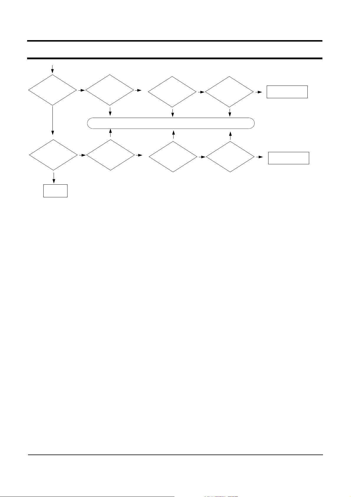
5. Troubleshooting
DMB function
is OK?
YES
Bluetooth
function is OK?
YES
End
NO
NO
Check driver status.
It is
problem.
Solution : Replace the defected part or revise the connectivity.
It is
problem.
Check driver status
No problem
No problem
Check DMB Module.
It is
problem.
It is
problem.
Check Bluetooth cable.
No problem
No problem
Check
Internal/Exter
nal Antenna
It is
problem.
It is
problem.
Check
Bluetooth
module.
No problem
Change Mainboard
and check it.
No problem
Change Mainboard
and check it.
5- 4

- This document cannot be used without the authorization of Samsung -
5. Troubleshooting
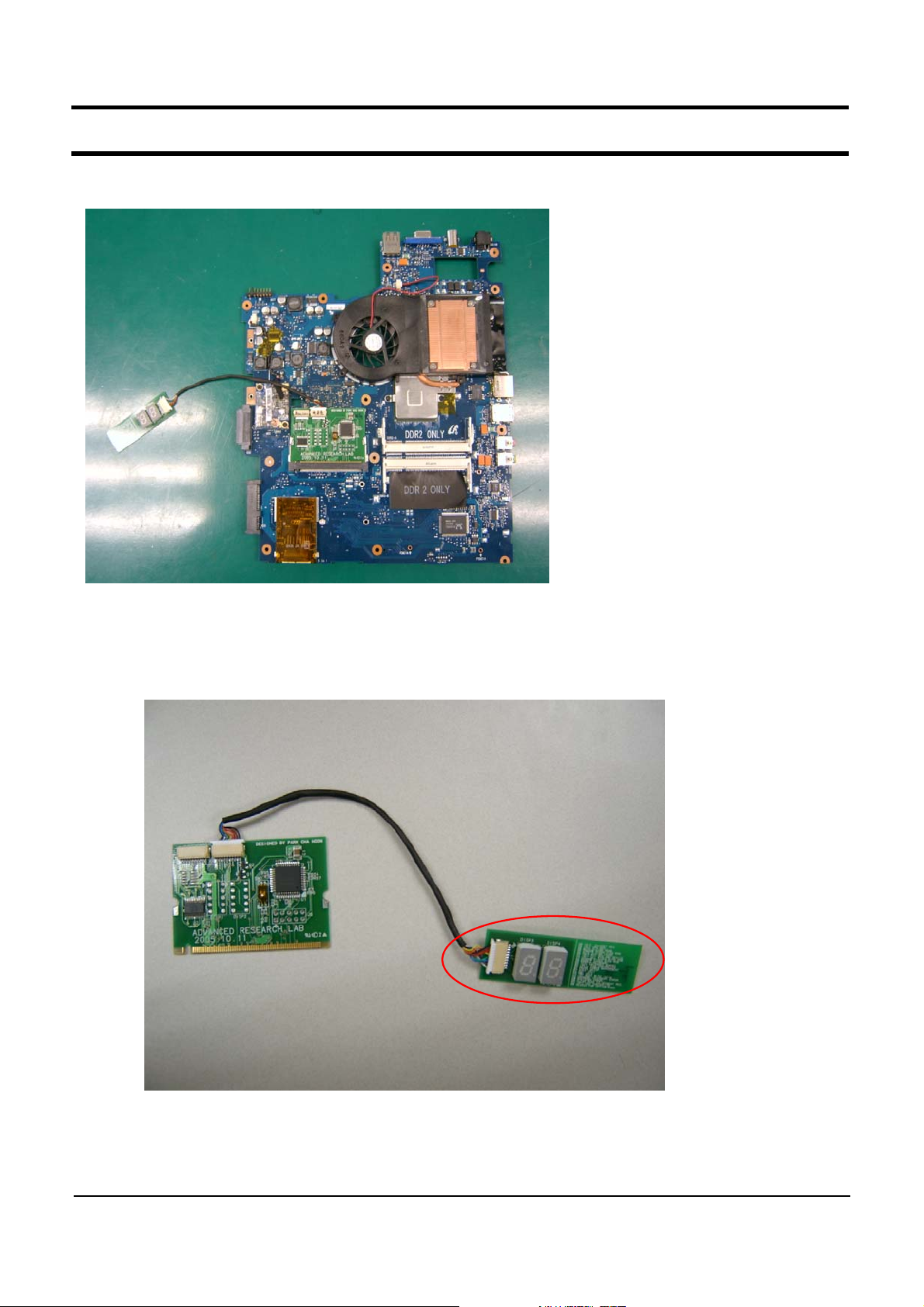
3) System Diagnosis
(1) System Diagnosis Card
The working status of the system is displayed by hexadecimal codes on the seven segment during
the post. If the system is working improperly, it is used to test the system is working in the proper way
after replacing the FRU caused system down or diagnosing the causes of the improper working without
taking apart the system.
(2) Debugging Code
If there is something wrong with the system, which can be circuit or parts, the systems working at
a specific code, The following is the debugging code list about the error of the system board.
Code Beeps POST Routine Description
02h Verify Real Mode
03h Disable Non-Maskable Interrupt
04h Get CPU type
06h Initialize system hardware
08h Initialize chipset with initial POST values
09h Set IN POST flag
0Ah Initialize CPU registers
0Bh Enable CPU cache
0Ch Initialize caches to initial POST values
0Eh Initialize I/O component
0Fh Initialize the local bus IDE
10h Initialize Power Management
11h Load alternate registers with initial POST values
12h Restore CPU control word during warm boot
13h Initialize PCI Bus Mastering devices
14h Initialize keyboard controller
16h 1-2-2-3
BIOS ROM checksum
17h Initialize cache before memory auto size
18h 8254 timer initialization
1Ah 8237 DMA controller initialization
1Ch Reset Programmable Interrupt Controller
20h 1-3-1-1 Test DRAM refresh
22h 1-3-1-3 Test 8742 Keyboard Controlle
24h Set ES segment register to 4 GB
26h Enable A20 line
28h Auto size DRAM
29h Initialize POST Memory Manager
2Ah Clear 512 KB base RAM
2Ch 1-3-4-1 RAM failure on address line xxxx*
2Eh 1-3-4-3
2Fh Enable cache before system BIOS shadow
30h 1-4-1-1
RAM failure on data bits xxxx* of low byte of memory bus
RAM failure on data bits xxxx* of high byte of memory bus
5- 5

- This document cannot be used without the authorization of Samsung -
5. Troubleshooting
32h Test the CPU bus-clock frequency
33h Initialize Phoenix Dispatch Manager
36h Warm start shutdown
38h Shadow system BIOS ROM
3Ah Auto size cache
3Ch Advanced configuration of chipset registers
3Dh Load alternate registers with CMOS values
42h Initialize interrupt vectors
45h POST device initialization
46h 2-1-2-3 Check the ROM copyright notice
48h Check the video configuration against CMOS
49h Initialize PCI bus and devices
4Ah Initialize all video adapters on the system
4Bh Quiet Boot start (optional)
4Ch Shadow video BIOS ROM
4Eh Display the BIOS copyright notice
50h Display the C P U type and speed
51h Initialize EISA board
52h Test the keyboard
54h Set key click if enabled
58h 2-2-3-1 Test for unexpected interrupts
59h Initialize POST display service
5Ah Display the prompt "Press F2 to enter SETUP"
5Bh Disable CPU cache
5Ch Test RAM between 512 and 640 KB
60h Test extended memory
62h Test extended memory address lines
64h Jump to UserPatch1
66h Configure advanced cache registers
67h Initialize Multi Processor APIC
68h Enable external and CPU caches
69h Setup System Management Mode (SMM) area
6Ah Display external L2 cache size
6Bh Load custom defaults (optional)
6Ch Display shadow-area message
6Eh Display possible high address for UMB recovery
70h Display error messages
72h Check for configuration errors
76h Check for keyboard errors
7Ch Set up hardware interrupt vectors
7Eh Initialize coprocessor if present
80h Disable onboard Super I/O ports and IRQs
81h Late POST device initialization
82h Detect and install external RS232 ports
83h Configure non-MCD IDE controllers
84h Detect and install external parallel ports
85h Initialize PC-compatible PnP ISA devices
5- 6

- This document cannot be used without the authorization of Samsung -
5. Troubleshooting
86h Re-initialize onboard I/O ports.
87h Configure Mothe board Configurable Devices
88h Initialize BIOS Data Area
89h Enable Non-Maskable Interrupts (NMIs)
8Ah Initialize Extended BIOS Data Area
8Bh Test and initialize PS/2 mouse
8Ch Initialize floppy controller
8Fh Determine number of ATA drives (optional)
90h Initialize hard-disk controllers
91h Initialize local-bus hard-disk controllers
92h Jump to UserPatch2
93h Build MPTABLE for multi-processor boards
95h Install CD ROM for boot
96h Clear huge ES segment register
97h Fixup Multi Processor table
98h 1-2 Search for option ROMs. One long, two short beeps on
che checksum failure
99h Check for SMART Drive (optional)
9Ah Shadow option ROMs
9Ch Set up Power Management
9Dh Initialize security engine (optional)
9Eh Enable hardware interrupts
9Fh Determine number of ATA and SCSI drives
A0h Set time of day
A2h Check key lock
A4h Initialize Typematic rate
A8h Erase F2 prompt
AAh Scan for F2 key stroke
ACh Enter SETUP
AEh Clear Boot flag
B0h Check for errors
B2h POST done - prepare to boot operating system
B4h 1 One short beep before boot
B5h Terminate QuietBoot (optional)
B6h Check password (optional)
B9h Prepare Boot
BAh Initialize DMI parameters
BBh Initialize PnP Option ROMs
BCh Clear parity checkers
BDh Display Multi Boot menu
BEh Clear screen (optional)
BFh Check virus and backup reminders
C0h Try to boot with INT 19
C1h Initialize POST Error Manager (PEM)
C2h Initialize error logging
C3h Initialize error display function
C4h Initialize system error handler
C5h PnPnd dual CMOS (optional)
5- 7
- This document cannot be used without the authorization of Samsung -
5. Troubleshooting
(3) Use of Debug card
-. Like upper picture, debug card is connected to MiniPCI Socket on Main board.
-. Debug code is shown at the viewer in red line.
5- 8