

samsung mx-j730-xa, mx-j730 Service Manual
MINI-CompactSystem
ModelNameMX-J730
ModelCodeMX-J730/XA
MANUAL
SERVICE
MINI-CompactSystem
1.Precaution
2.ProductSpecication
3.DisassemblyandReassembly
4.Troubleshooting
5.PCBDiagram
6.SchematicDiagram
MX-J730
Contents
RefertotheservicemanualintheGSPN(seetherearcover)formoreinformation.

Contents
Contents
1.Precaution........................................................................................................................................1−1
1.1.SafetyPrecautions...................................................................................................................1−1
1.2.ServicingPrecautions...............................................................................................................1−3
1.3.PrecautionsforElectrostaticallySensitiveDevices(ESDs)..............................................................1−4
1.4.InstallationPrecautions.............................................................................................................1−5
2.ProductSpecication.........................................................................................................................2−1
2.1.ProductFeature.......................................................................................................................2−1
2.2.Specications..........................................................................................................................2−2
2.3.SpecicationsAnalysis.............................................................................................................2−3
2.4.Accessories............................................................................................................................2−4
2.4.1.SuppliedAccessories...................................................................................................2−4
3.DisassemblyandReassembly..............................................................................................................3−1
3.1.MainDisassemblyandReassembly.............................................................................................3−1
3.2.DECKDisassemblyandReassembly...........................................................................................3−7
4.Troubleshooting................................................................................................................................4−1
4.1.CheckpointsbyErrorMode.......................................................................................................4−1
4.1.1.NoPower...................................................................................................................4−2
4.1.2.NoOutput..................................................................................................................4−4
4.2.MeasurestobetakenwhentheProtectionCircuitoperates...............................................................4−5
4.2.1.OperationofPowerBlockProtectionCircuit....................................................................4−5
4.2.2.CheckAMPinPowerProtection....................................................................................4−6
4.3.MICOM,MPEGInitialization&Update......................................................................................4−7
4.4.Buyer-RegionCodeSettingMethod............................................................................................4−8
4.4.1.TheinsertingmethodofRegionCodeafterreplacingtheMainPBA.....................................4−8
5.PCBDiagram...................................................................................................................................5−1
5.1.WiringDiagram.......................................................................................................................5−1
5.2.FRONTPCBTop....................................................................................................................5−2
5.2.1.PinConnection...........................................................................................................5−3
5.3.FRONTPCBBottom...............................................................................................................5−4
5.4.MAINPCBTop......................................................................................................................5−5
5.4.1.PinConnection...........................................................................................................5−6
5.4.2.TestPointWaveForm..................................................................................................5−7
5.5.MAINPCBBottom..................................................................................................................5−8
5.6.SMPSPCBTop.......................................................................................................................5−9
5.6.1.PinConnection...........................................................................................................5−10
5.7.SMPSPCBBottom..................................................................................................................5−11
6.SchematicDiagram...........................................................................................................................6−1
6.1.OverallBlockDiagram.............................................................................................................6−1
iCopyright©1995-2013SAMSUNG.Allrightsreserved.

Contents
6.2.FRONT-1...............................................................................................................................6−2
6.3.FRONT-2...............................................................................................................................6−3
6.4.FRONT-3...............................................................................................................................6−4
6.5.MAIN-1.................................................................................................................................6−5
6.6.MAIN-2.................................................................................................................................6−6
6.7.MAIN-3.................................................................................................................................6−7
6.8.MAIN-4.................................................................................................................................6−8
6.8.1.TestPointWaveForm..................................................................................................6−9
6.9.MAIN-5.................................................................................................................................6−10
6.10.SMPS....................................................................................................................................6−11
Copyright©1995-2013SAMSUNG.Allrightsreserved.ii
1.Precaution
DEVICE
UNDER
TES T
LEAKAGE
CUR RE NT
TES TER
TES T ALL
EXPO SED ME TAL
SU RFACES
2-WIRE CORD
ALSO TE S T WITH
PLUG REVERS ED
(US ING AC
ADAPTER P LUG
AS R EQ UIRED)
EARTH
GR OUND
(RE ADING
SH OULD NOT BE
ABOVE 0.5m A)
1.Precaution
FollowthesesafetyinstructionswhileservicingtheESDtopreventdamageandtoprotectagainstpotentialhazards
suchaselectricalshockandX-rays.
1.1.SafetyPrecautions
1)Whenreinstallingthechassisanditsassemblies,besuretorestorealloftheprotectivedevices,includingthecontrol
knobsandthecompartmentcovers.
2)Makesurethattherearenocabinetopeningsthroughwhichpeople(particularlychildren)canmakecontactwith
dangerousinternalcomponents.
3)DesignAlterationWarning:
Neveralteroraddtothemechanicalorelectricaldesignoftheunit.
Example:Donotaddauxiliaryaudioorvideoconnectors.Suchalterationsmightcreateasafetyhazard.
Also,anydesignchangesoradditionswillvoidthemanufacturer’swarranty.
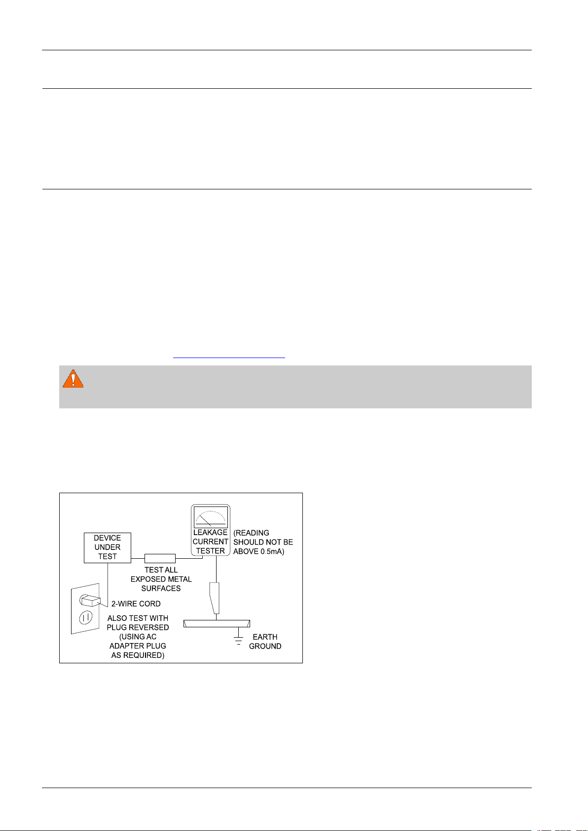
4)LeakageCurrentHotCheckFigure1.1
ACLeakageTest:
WARNING
Donotuseanisolationtransformerduringthistest.Usealeakage-currenttesterorameteringsystemthatcomplies.
Withtheunitcompletelyreassembled,plugtheACcorddirectlyintoaACoutlet.Withtheunit’spowerswitchedfrom
theONtotheOFFposition,measurethecurrentbetweenaknowngroundandallexposedmetalparts.
KnownGrounds-Earth
KnownMetalparts-screwheads,metalcabinets,etc.
Figure1.1ACLeakageTest
1-1Copyright©1995-2013SAMSUNG.Allrightsreserved.
1.Precaution
Ante nna
Term inal
ohm
Expo sed
Meta l Part
Ohmmet er
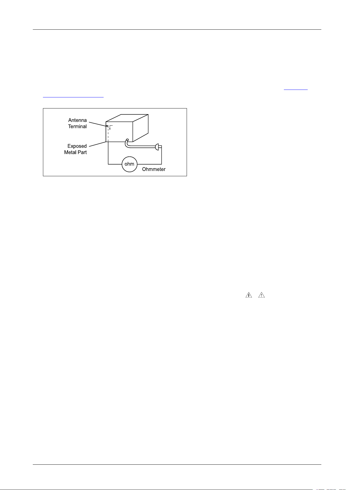
5)InsulationResistanceColdCheck:
(1)Withtheunit’sACplugdisconnectedfromtheACsource,connectanelectricaljumperacrossthetwoACprongs.
(2)SetthepowerswitchtoON.(3)MeasuretheresistancebetweentheshortedACplugandanyexposedmetallicparts.
Example:screwheads,metalcabinets,antennaport,etc.Ifanyoftheexposedmetallicpartshasareturnpathtothe
chassis,themeasuredresistanceshouldbebetween1and5.2megohms.Ifthereisnoreturnpath,themeasured
resistanceshouldbe“innite.”Iftheresistanceisoutsidetheselimits,ashockhazardmightexist.SeeFigure1.2
InsulationResistanceTest
Figure1.2InsulationResistanceTest
6)Components,partsandwiringthatappeartohaveoverheatedorthatareotherwisedamagedshouldbereplacedwith
partsthatmeettheoriginalspecications.Alwaysdeterminethecauseofdamageoroverheating,andcorrectany
potentialhazards.
7)Observetheoriginalleaddress,especiallynearthefollowingareas:Antennawiring,sharpedges,andespeciallytheAC
andhighvoltagepowersupplies.Alwaysinspectforpinched,out-of-place,orfrayedwiring.
Donotchangethespacingbetweencomponentsandtheprintedcircuitboard.ChecktheACpowercordfordamage.
Makesurethatnowiresorcomponentstouchthermallyhotparts.
8)ProductSafetyNotice:
Someelectricalandmechanicalpartshavespecialsafety-relatedcharacteristicswhichmightnotbeobviousfromvisual
inspection.Thesesafetyfeaturesandtheprotectiontheygivemightbelostifthereplacementcomponentdiffersfrom
theoriginal—evenifthereplacementisratedforhighervoltage,wattage,etc.
9)Componentsthatarecriticalforsafetyareindicatedinthecircuitdiagrambyshading,
or.Usereplacement
componentsthathavethesameratings,especiallyforameresistanceanddielectricstrengthspecications.A
replacementpartthatdoesnothavethesamesafetycharacteristicsastheoriginalmightcreateshock,reorother
hazards.
Copyright©1995-2013SAMSUNG.Allrightsreserved.1-2

1.Precaution
1.2.ServicingPrecautions
1)Servicingprecautionsareprintedonthecabinet.Followthem.
2)Alwaysunplugtheunit’sACpowercordfromtheACpowersourcebeforeattemptingto:
(a)Removeorreinstallanycomponentorassembly ,(b)Disconnectanelectricalplugorconnector,(c)Connecta
testcomponentinparallelwithanelectrolyticcapacitor.
3)Somecomponentsareraisedabovetheprintedcircuitboardforsafety.Aninsulationtubeortapeissometimesused.
Theinternalwiringmaybeclampedtopreventcontactwiththermallyhotcomponents.Reinstallallsuchelements
totheiroriginalposition.
4)Afterservicing,alwayscheckthatthescrews,componentsandwiringhavebeencorrectlyreinstalled.Makesurethat
theportionaroundtheservicedparthasnotbeendamaged.
5)ChecktheinsulationbetweenthebladesoftheACplugandaccessibleconductiveparts(examples:metalpanels,
inputterminalsandearphonejacks).
6)InsulationCheckingProcedure:
DisconnectthepowercordfromtheACsource.Connectaninsulationresistancemeter(500V)tothebladesofthe
ACplug.TheinsulationresistancebetweeneachbladeoftheACplugandaccessibleconductiveparts(seeabove)
shouldbegreaterthan1megohm.
7)NeverdefeatanyoftheB+voltageinterlocks.DonotapplyACpowertotheunit(oranyofitsassemblies)unlessall
solid-stateheatsinksarecorrectlyinstalled.
8)Alwaysconnectatestinstrument’sgroundleadtotheinstrumentchassisgroundbeforeconnectingthepositivelead;
alwaysremovetheinstrument’sgroundleadlast.
CAUTION
Firstreadthe“SafetyPrecautions”sectionofthismanual.Ifsomeunforeseencircumstancecreatesaconictbetweenthe
servicingandsafetyprecautions,alwaysfollowthesafetyprecautions.
1-3Copyright©1995-2013SAMSUNG.Allrightsreserved.

1.Precaution
1.3.PrecautionsforElectrostaticallySensitiveDevices(ESDs)
Somesemiconductor(“solidstate”)devicesareeasilydamagedbystaticelectricity.
SuchcomponentsarecalledElectrostaticallySensitiveDevices(ESDs).
Examplesincludeintegratedcircuitsandsomeeld-effecttransistors.
Thefollowingtechniqueswillreducetheoccurrenceofcomponentdamagecausedbystaticelectricity:
1)Immediatelybeforehandlinganysemiconductorcomponentsorassemblies,draintheelectrostaticchargefromyour
bodybytouchingaknownearthground.Alternatively,wearadischargingwrist-strapdevice.(Besuretoremoveit
priortoapplyingpower–thisisanelectricshockprecaution.)
2)AfterremovinganESD-equippedassembly,placeitonaconductivesurfacesuchasaluminumfoiltoprevent
accumulationofelectrostaticcharge.
3)Donotusefreon-propelledchemicals.ThesecangenerateelectricalchargesthatdamageESDs.
4)Useonlyagrounded-tipsolderingironwhensolderingorunsolderingESDs.
5)Useonlyananti-staticsolderremovaldevice.Manysolderremovaldevicesarenotratedas“anti-static”(thesecan
accumulatesufcientelectricalchargetodamageESDs).
6)DonotremoveareplacementESDfromitsprotectivepackageuntilyouarereadytoinstallit.
MostreplacementESDsarepackagedwithleadsthatareelectricallyshortedtogetherbyconductivefoam,aluminum
foilorotherconductivematerials.
7)ImmediatelybeforeremovingtheprotectivematerialfromtheleadsofareplacementESD,touchtheprotectivematerial
tothechassisorcircuitassemblyintowhichthedevicewillbeinstalled.
8)MinimizebodymotionswhenhandlingunpackagedreplacementESDs.Motionssuchasbrushingclothestogether,or
liftingafootfromacarpetedoorcangenerateenoughstaticelectricitytodamageanESD.
Copyright©1995-2013SAMSUNG.Allrightsreserved.1-4

1.Precaution
1.4.InstallationPrecautions
1)Keeptheproductawayfromaheatsourcesuchascandlelight,mosquitorepellentincense,heatingequipment,ordirect
sunlight.Otherwise,thismaycausere.
2)Donotinstalltheproductonaplacethatisshaking,tilted,unstable,orseriouslyvibrating.Theproductmaydroptoget
damagedorinjureaperson.Ifusingtheproductinahighlyvibratingplace,itmaybebrokenorcausere.
3)Whenmovingtheproduct,turnoffthepowerswitchandunplugalltheconnectedcableswiththeproductsuchasthe
powerplugandantennacable.Ifthepowercordisdamaged,thismaycauseelectricshockorre.
4)Secureroomforventilation.Keepatleast10cmofdistancefromtherearwall,andatleast5cmfromeithersidewall.
5)Installingtheproductinaspecialplacelikebelowratherthannormalenvironmentmaycauseseriousqualityconcerns
duetoitsspecialconditions.Ifthisisthecase,makesuretocontactalocalSamsungservicecenterbeforeinstallingthe
product.(Specialplaces:aplacewherealargeamountofdustisaccumulated;wherechemicalsubstancesareused
ortheambienttemperatureistoohighorlow;aplacethatisfullofmoistureorwater;intransportationvehicles
suchasacar;orinpublicplacessuchastheairportorsubwaystationwheretheproductissupposedtooperate
uninterruptedlyforalongtime)
6)Keepthepackagingplasticwrapperoutofchildren'sreach.Ifchildrenplaywithitimproperly,theymaygetsuffocated.
7)Ifinstallingtheproductonadisplaycabinet,shelf,desk,etc.,keeptheproductfromprotrudingonitslowerside.Ifthe
productfalls,itmaybreakorcausephysicalinjury .Useonlythedisplaycabinetorshelfthatfullycoverstheproduct.
8)Ifusinglithiumbatteries,carefullyreadthefollowingprecautions:
NOTE
•Ensurethebatteriesareinsertedintherightdirection.Otherwise,theymaycauseanexplosion.Disposeofusedbatteries
accordingtothemanufacturer'sinstructions.
•Donotexposethebatterytore.
•Donotdisassemble,short-cut,orheatthebattery.
•Useonlythesametypeandsizeofbatteriesforreplacement.
•Donotexposethebatterytoreorexcessiveheat.
1-5Copyright©1995-2013SAMSUNG.Allrightsreserved.

2.ProductSpecication
2.1.ProductFeature
■Power
•2.0CH:600WTotalRMS
•IRAmp
■SpecializedFunctionin2015
•CDRipping(Abletorippingwhilelistening)
•GIGAMode
•Demo/DemoMusicPlay
•FootballMode
2.ProductSpecication
•Non-StopMusicRelay
•CD/USBProgram
•AutoChange
■Connectivity
•USBHost(TwinUSB)
•TVSoundConnect
•Bluetooth
•BTPowerOn
■Disc
•Type:1Tray(12cmCD)
•Compatible:CDDA/CD-R/R W ,WMA,MP3,ISO9660
Copyright©1995-2013SAMSUNG.Allrightsreserved.2-1
2.ProductSpecication
2.2.Specications
■BasicSpecication
Weight2.45Kg
Dimensions200(W)x308.5(H)x230(D)mm
General
FMTuner
CDDisc
Amplier
Operating
TemperatureRange
OperatingHumidity
Range
Signal/Noiseratio55dB
Usablesensitivity12dB
Totalharmonic
distortion
CD:12cm
(CompactDisc)
Frontspeaker
output
Frontspeaker
output
+5°C~+35°C
10%to75%
0.6%
ReadingSpeed:4.8~5.6m/sec.
MaximumPlayTime:74min.
MX-J650:440Watts(10%THD)
220W/CH(4Ω/100Hz)
MX-J730:600Watts(MAX)
300W/CH(4Ω/100Hz)
250W/CH(4Ω/100Hz)
Frequencyrange20Hz~20KHz
S/NRatio80dB
Channelseparation65dB
Inputsensitivity(AUX)2V
NOTE
•SamsungElectronicsCo.,Ltdreservestherighttochangethespecicationswithoutnotice.
•Weightanddimensionsareapproximate.
•Designandspecicationsaresubjecttochangewithoutpriornotice.
•ForthepowersupplyandPowerConsumption,refertothelabelattachedtotheproduct.
2-2Copyright©1995-2013SAMSUNG.Allrightsreserved.
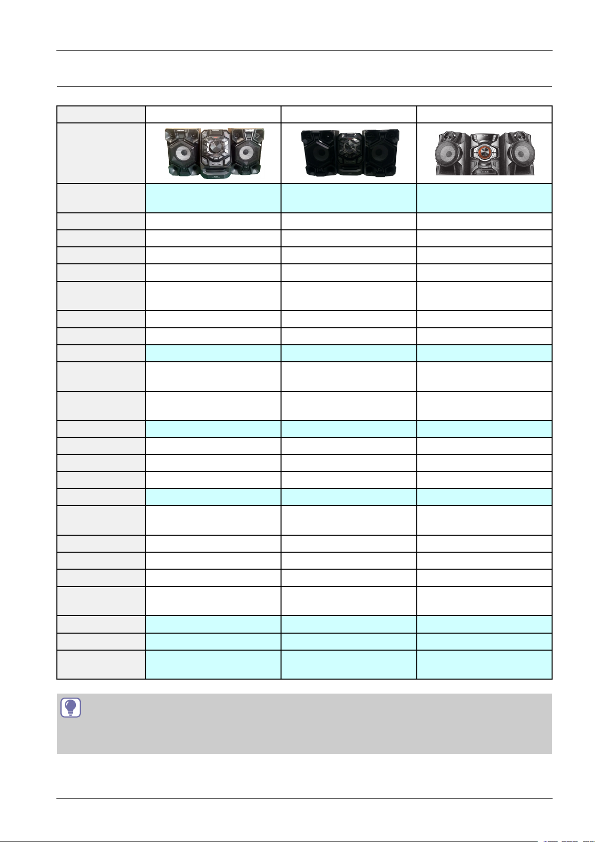
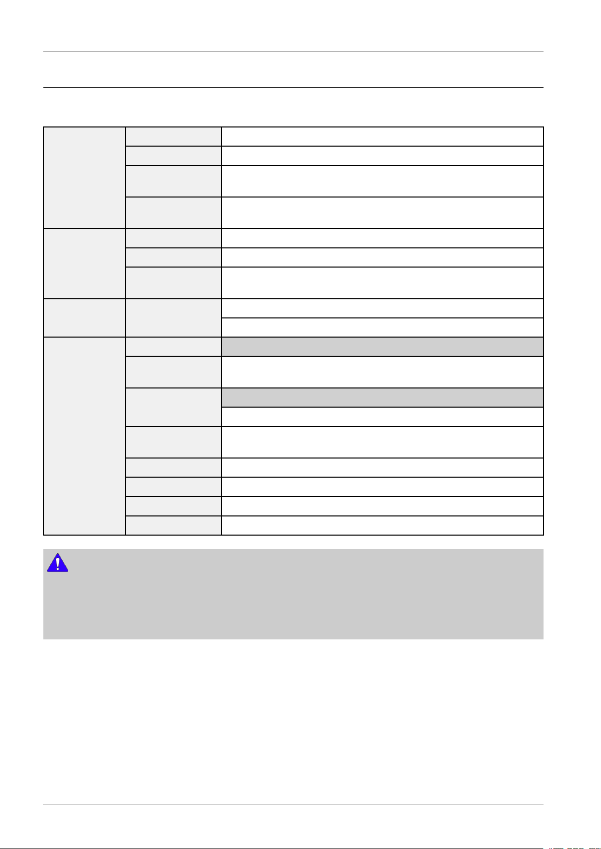
2.3.SpecicationsAnalysis
ModelNameMX-J730MX-J650MX-H730
Photo
2.ProductSpecication
TotalPower(RMS
10%)
SPKCHANNEL2.0ch2.0ch2.0ch
FRONTDISPLA YVFDVFDVFD
3DBeatLightingXXX
GIGASOUNDOOO
SPKLED
LIGHTING
DJBEATXXX
BEATW A VINGXXX
TVSoundOOX
COMPATIBLE
DISC
COMPATIBLE
FILE
USBHOST1.0221
CDRIPPINGOOO
BLUETOOTHOOO
AUDIOIN(RCA)OOO
CDDA/CD-R/CD-RWCDDA/CD-R/CD-RWCDDA/CD-R/CD-RW
500W440W550W
XXX
WMA/MP3WMA/MP3WMA/MP3
MICINXXO
HEADPHONE
OUT
VIDEOOUTXXX
FM/AMO/OO/OO/O
SPKIMPEDANCEFront4ohmFront:4ohmFront:4ohm
STBYPOWER
CONSUMPTION
MAINSIZE(mm)200(W)X308.5(H)X230(D)200(W)X308.5(H)X230(D)203(W)X306(H)X256.5(D)
SPKSIZE(mm)232(W)X331(H)X294(D)223(W)X325(H)X280(D)230(W)X359(H)X299.7(D)
PackageWeight
(Kg)
TIP
O:FeatureIncluded
X:NotIncluded
XXX
0.45W↓0.45W↓0.45W↓
1412.211.71
Copyright©1995-2013SAMSUNG.Allrightsreserved.2-3
2.ProductSpecication
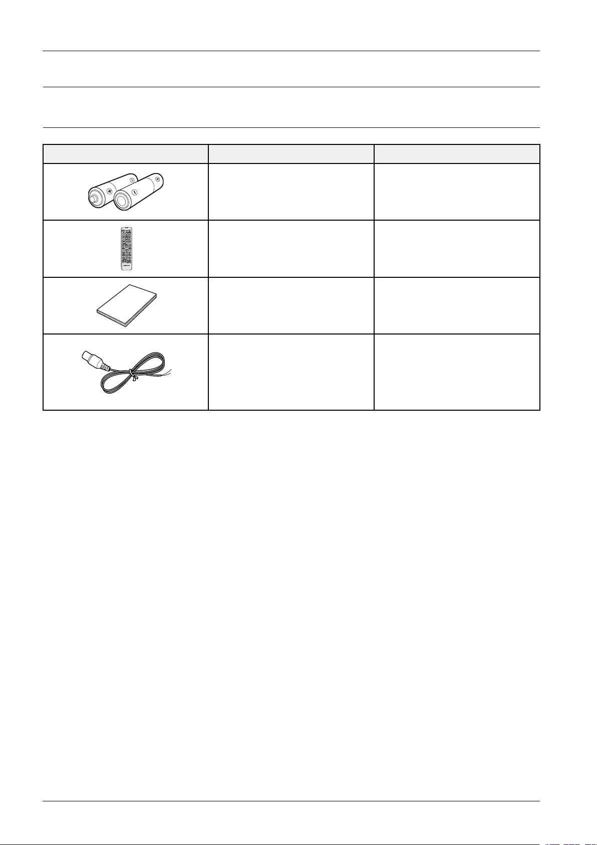
2.4.Accessories
2.4.1.SuppliedAccessories
AccessoriesItemItemcode
Batteries(AAA)4301-000116
RemoteControlAH59-02694B
User’sManualAH68-02791D
FMAntennaAH42-00021A
2-4Copyright©1995-2013SAMSUNG.Allrightsreserved.
3.DisassemblyandReassembly
3.DisassemblyandReassembly
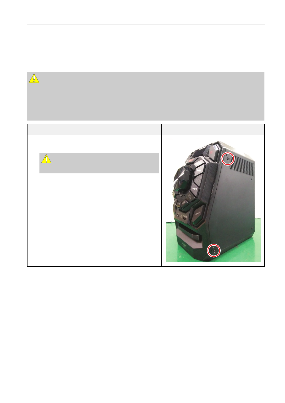
3.1.MainDisassemblyandReassembly
CAUTION
•Becarefultofollowthedisassemblysequencedescribedinthemanual.Otherwise,theproductmaybedamaged.
•BesuretocarefullyreadandunderstandthesafetyinstructionsbeforeperforminganyworkastheICchipson
thePCBarevulnerabletostaticelectricity.
•Inordertoassemblereversetheorderofdisassembly .
DescriptionDescriptionPhoto
1.Unfasten4screwsonthe2sideCover.
:BH,+,B,M3,L10,ZPC(BLK)
CAUTION
Becarefulnottomakeanyscratchesasyouremovethem.
Copyright©1995-2013SAMSUNG.Allrightsreserved.3-1
3.DisassemblyandReassembly
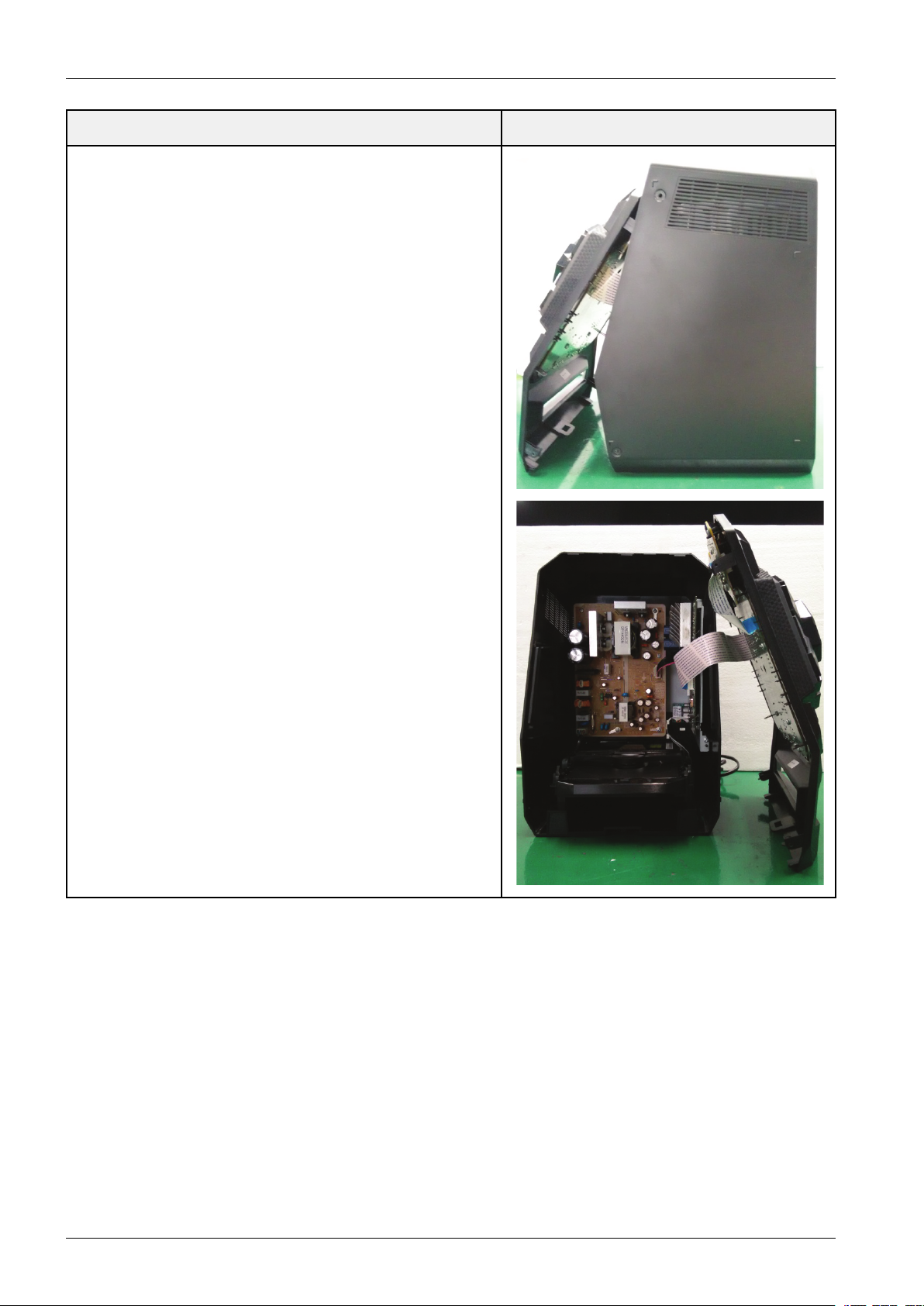
2.SeparatetheFrontPanel.
DescriptionDescriptionPhoto
3-2Copyright©1995-2013SAMSUNG.Allrightsreserved.
DescriptionDescriptionPhoto
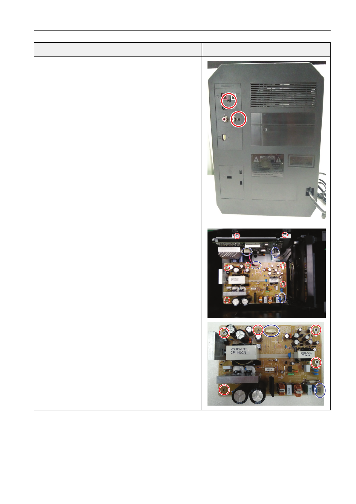
3.Unfasten2screws,andthenseparatetheRearPCBfromRear
Panel.
:BH,+,B,M3,L10,ZPC(BLK)
3.DisassemblyandReassembly
4.Unfasten5screwsinSMPSanddetachAC-CORD&13Pshield
wire.
:BH,+,-,B,M3,L10,ZPC(WHT)
Copyright©1995-2013SAMSUNG.Allrightsreserved.3-3
3.DisassemblyandReassembly
DescriptionDescriptionPhoto
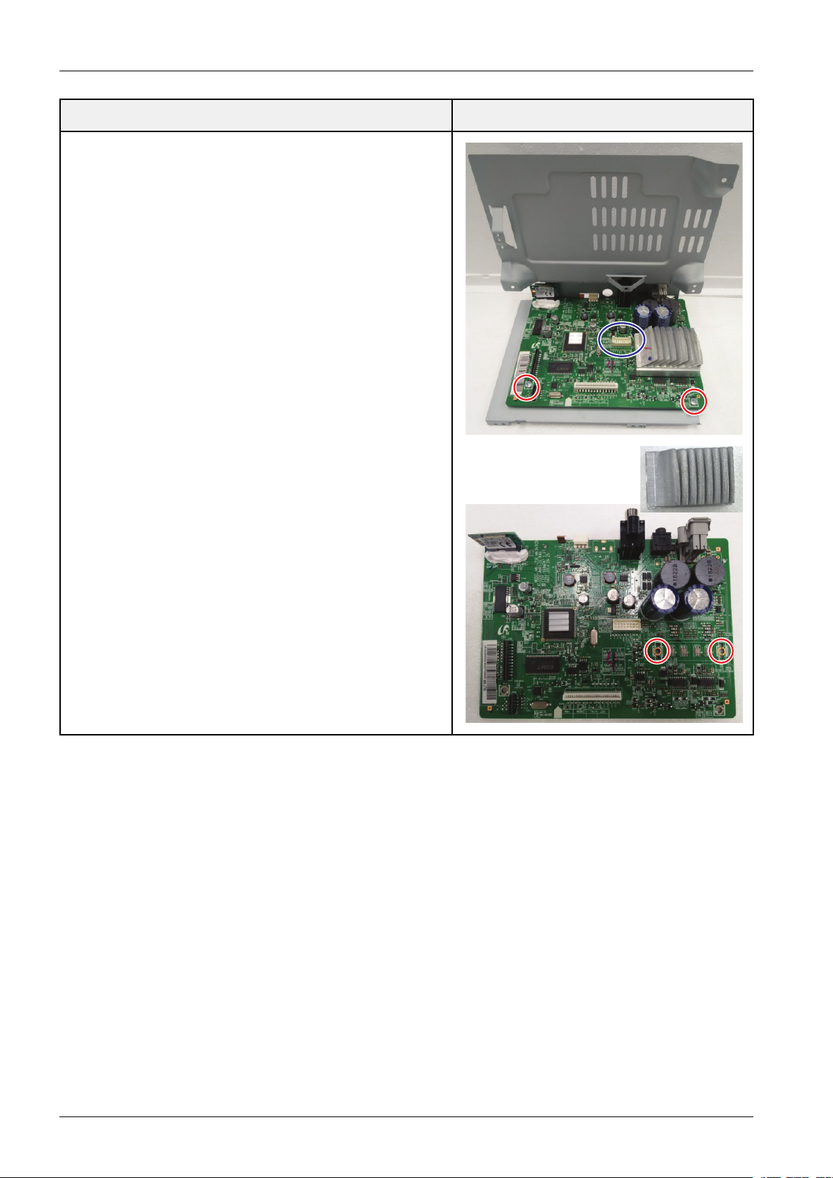
5.Unfasten4kittingscrewsanddetachDECKwire.
:BH,+,-,B,M3,L10,ZPC(WHT)
3-4Copyright©1995-2013SAMSUNG.Allrightsreserved.
DescriptionDescriptionPhoto
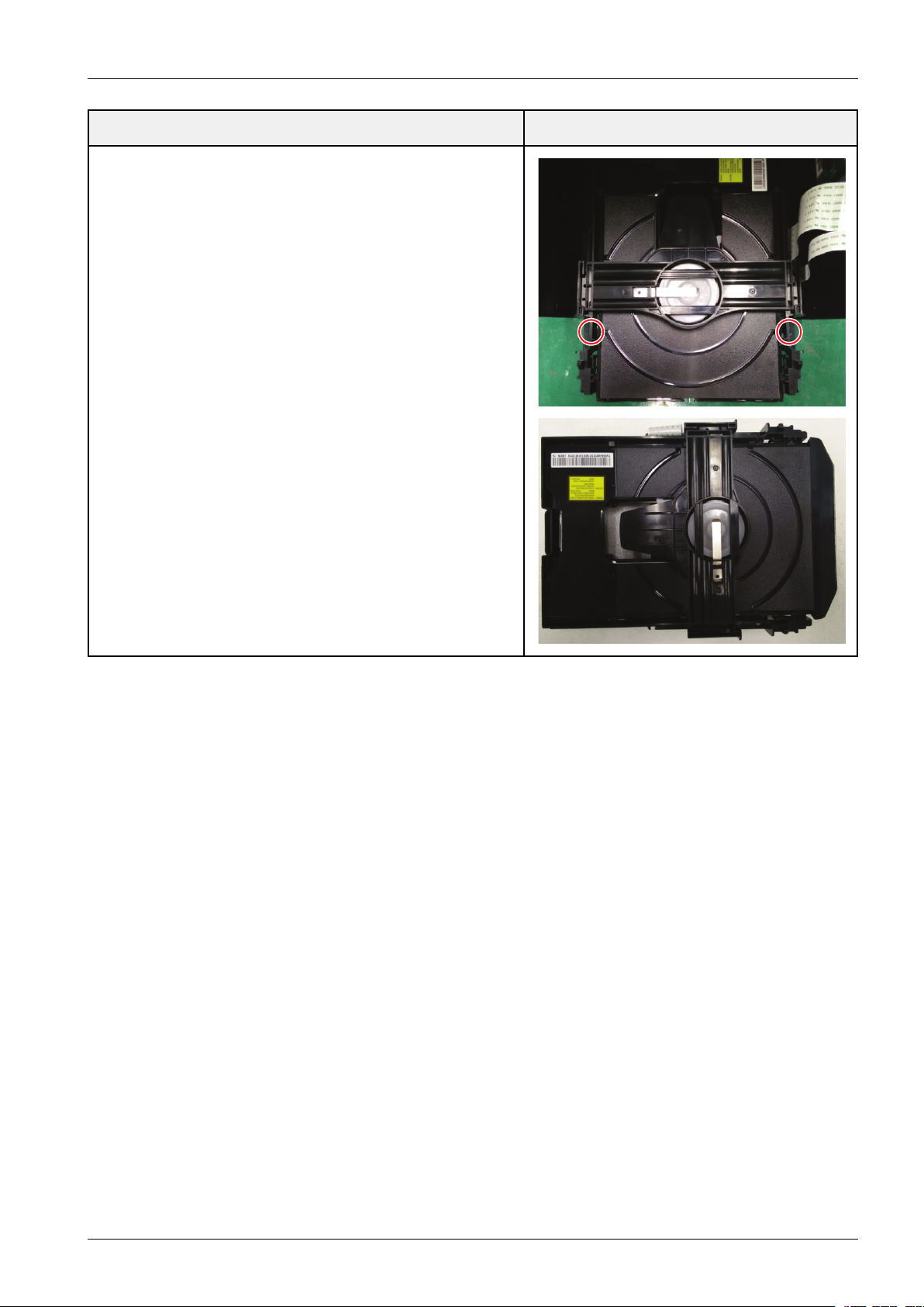
6.Unfasten2screwsfrominside,separateDECKfrommecha.
:BH,+,B,M3,L10,ZPC(BLK)
3.DisassemblyandReassembly
Copyright©1995-2013SAMSUNG.Allrightsreserved.3-5
 Loading...