

Samsung ML-6060 Service Manual
SERVICE
LASER PRINTER
ML-6060
ML-6060N
SAMSUNG
Manual
LASER PRINTER CONTENTS
1. Precautions
2. Specifications
3. Disassembly and Reassembly
4. Troubleshooting
5. Exploded Views and Parts List
6. Electrical Parts List
7. Block Diagram
8. Connection Diagram
9. Schematic Diagrams
Download Service Manual And Resetter Printer at http://printer1.blogspot.com
Samsung Electronics 1-1
1. Precautions
1-1 Safety Precautions
Read each caution carefully:
1. Do not use this printer near water or when
exposed to inclement weather.
2. Do not place this printer on an unstable cart, stand
or table; the product may fall, causing serious
damage to the product.
3. Slots and openings in the cabinet are provided for
ventilation. To ensure reliable operation and to protect the printer from everheating, do not block or
cover any of these openings. Do not place the
printer in an enclosure unless the enclosure provides adequate ventilation.
4. Never push objects of any kind into the printer
through the cabinet ventilation slots as they may
touch dangerous high voltage points, create short
circuits, cause a fire, or produce an electrical
shock. Never spill liquid of any kind on the printer.
5. Do not place the printer in a location where someone may trip on the cords.
6. Select a work surface that is large enough to hold
the printer.
7. Position the printer within six feet of the computer
and within five feet of an electrical outlet.
8. Operate this printer using the power source (110V,
220V, etc) indicated on the marking label. If you
are not sure of the type of power source available,
consult your dealer or local power company.
9. If you need to use an extension power cord with
this printer, make sure that it uses a three-wire
grounded cord and that the total ampere ratings for
all of the products using the extension do not
exceed the extension cord ampere rating. Also,
make sure that the total of all products plugged
into the wall outlet does not exceed 15 amperes.
10. Do not allow anything to rest on the power cord or
data communications cable.
11. Unplug this printer from the wall outlet before
cleaning. Do not use liquid cleaners or aerosol
sprays. Use a damp cloth for cleaning.
12. Do not touch the surface of the photo-sensitive
drum as marks or scratches may impair print quality.
13. Do not expose the drum unit to direct light for prolonged periods.
14. Use only standard papers, OHP films, and
approved envelopes. Feed OHP films though the
manual feed slot only. See specifications for
approved papers and envelopes.
15. Other than replacing consumables such as paper
and toner, refer all questions to qualified service
personnel.
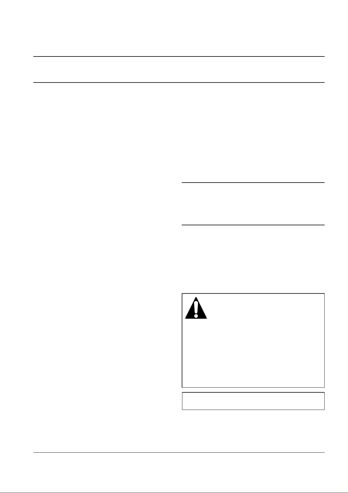
LASER STATEMENT (LASERTURVALLISUUS)
WARNING : NEVER OPERATE AND SERVICE THE PRINTER
WITH THE PROTECTIVE COVER REMOVED
FROM LASER/SCANNER ASSEMBLY. THE
REFLECTIVE BEAM, ALTHOUGH INVISIBLE, CAN
DAMAGE YOUR EYES.
Class 1 laser product
Luokan 1 laserlaite
Klass 1 laser apparat
Allonpituus 770-795nm
Teho 0.29mW±0.02mW
CAUTION
VORSICHT
ATTENTION
ATTENZIONE
PRECAUCION
CAUTION : Avoid exposure to invisible laser radiation when the
development unit is not installed.
INVISIBLE LASER RADIATION WHEN
THIS COVER OPEN. DO NOT OPEN
THIS COVER.
UNSICHTBARE LASERSTRAHLUNG,
WENN ABDECKUNG GEOFFNET.
NIGHT DEM STRAHL AUSSETZEN.
REYONNEMENT LASER INVISIBLE EN CAS D’OUVERTURE. EXPOSITION DANGERUSE AU FAISCEAU.
RADIAZIONE LASER INVISIBLE IN CASO DI
APERTURA. EVITARE L’ESPOSIZONE LAFASCIO.
REDIACION LASER INVISIBLE CUANDO SE
ABRE. EVITAR EXPONERSE AL RAYO.
Download Service Manual And Resetter Printer at http://printer1.blogspot.com

1. Before disassembly, pull the power plug from the AC
power connector.
2. To avoid spilling toner inside the machine, do not turn
the printer over or on its side before removing the
developer cartridge.
3. Faulty installation of DRAMs may cause permanent
damage to the Laser Printer.
4. Use only+5V power for video controller-related circuitry.
5. When replacing parts, use only the same type of part
as the original. Replacing components with a second
vendor’s part may cause faulty operation.
6. Check the insulation between the blades of the AC
plug and accessible conductive parts (examples :
metal panels and input ports).
7. Insulation Checking Procedure:
Disconnect the power cord from the AC power
source. Connect an insulation resistance meter
(500V) to the blades of the AC plug.
The insulation resistance between each blade of the
AC plug and accessible conductive parts (see left)
should be greater than 1 megaohm.
8. Never defeat any of the B+ voltage interlocks. Do not
apply AC power to the unit (or any of its assemblies)
unless all solid-state heat sinks are correctly installed.
9. Always connect a test instrument’s ground lead to the
instrument chassis ground before connecting the positive lead; always remove the instrument’s ground
lead last.
1-2 Samsung Electronics
Precautions
1-2 Servicing Precautions
Note : Requirements for AC power are described on the label affixed to the rear of the printer. Check the AC
voltage rating requirement before use.
CAUTION : Be sure the power is off to the chas-
sis or circuit board, and observe all
other safety precautions
1. Immediately before handling any semiconductor components assemblies, drain the electrostatic charge
from your body by touching a known earth ground.
Alternatively, wear a discharging wrist strap device.
(Be sure to remove the strap before applying power
to the unit under test to avoid potential shock.)
2. After removing ESD-equipped assembly, place it on a
conductive surface such as aluminum foil to prevent
accumulation of an electrostatic charge.
3. Do not use freon-propelled chemicals. These can
generate electrical charges sufficient to damage
ESDs.
4. Use only a ground-tip soldering iron when soldering
or desoldering ESDs.
5. Use only anti-static solder removal device. Some solder removal devices are not rated as “antistatic;”these can accumulate sufficient electrical
charge to damage ESDs.
1-3 ESD Precautions
Some semiconductor (“solid state”) devices are easily damaged from static electricity. Such components commonly are called Electrostatically Sensitive Devices (ESDs); examples include integrated circuits (ICs), LargeScale Integrated circuits (LSIs), some field-effect transistors, and semiconductor chip components. The following techniques will reduce the occurrence of component damage caused by static electricity:
Download Service Manual And Resetter Printer at http://printer1.blogspot.com
Item Specification & Description
Engine ML-6060
Print Speed 12PPM (A4 Size, 5% Character Pattern)
Resolution True 600 x 600 dpi, 1200 DPI class with SRT
Source of Light Laser Diode (LSU:Laser Scanner Unit) + Electrophotography
Print Method Non-impact Electrophotography
Feed Method Cassette & Manual, Option Feeder
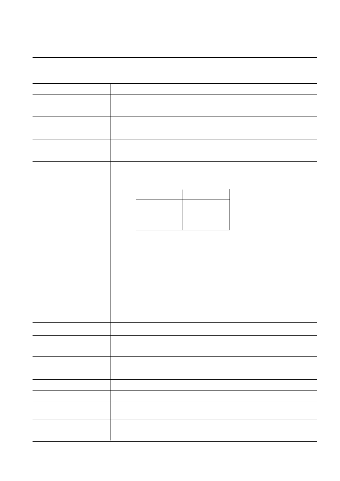
Paper Handling (input) *Size
(1) Standard : A4, Letter, Legal, B5, Executive, Folio
(2) Envelope : MP Tray only
Paper Type Paper size(mm
2
)
Monarch 98.5 x 190.5
Com-10 104.9 x 241.3
Intl-DL 110 x 220
Intl C5 162 x 229
(3) Universal type
Length : 150 ~ 356 mm
Width : 90 ~ 216 mm
*Weigh : For Cassette, 60 ~ 90 g/m
2
For MPF, 60 ~ 143 g/m
2
Paper Handing (output) Face Down : 250 sheets, Face Up : 20 sheets
Feed Capacity Cassette : 550 sheets of paper (75g/m2)
MP Tray : 100 sheets of paper (75g/m2)
30 sheets of transparencies
10 envelopes or card stocks
25 paper labels
Option Cassette : 550 sheets of paper
Warm-up time 30 seconds or less (23°C, 50%)
First Print Time Tray1 : 15seconds or less
Tray2 : 17seconds or less
Power Rating AC100~120V/ 220~240V(±15%), 50/60Hz (±3%)
Power Consumption During Printing : 250WH (average)
Power Saving During Sleep : Less than 12W
Consumption Less than 50W during 1 hour when it turned on
Certification & Compliance 110V : UL,CSA,CDRH,FDA
220V : GS,SEMKO,FIMKO,NEMKO,DEMKO
Acoustic Noise Stand by : Less than 35dB, Operating : Less than 48dB
Toner Supply Print Cartridge
2. Specifications
Note: It is subject to change without notice.
Samsung Electronics 2-1
Download Service Manual And Resetter Printer at http://printer1.blogspot.com

2-2 Samsung Electronics
Specifications
Item Specification & Description
Printing Area No-print area : 3mm from edge(Top,Bottom,Left,Right) of listed core media
No-print area : 3mm from edge(Top,Bottom,Left,Right) of envelope
Operating Environment Temperature : 10~30°C, Humidity : 20~80%RH
Storage Environment Temperature : 0~35°C, Humidity : 10~90%RH
Weigh Net : Max 11Kg, Gross : 15.5Kg
External Dimension 409.1 (W) x 362 (D) x 298.5 (H)mm
Print Cartridge Life Span : 6,000 pages, 5% Pattern
Developing : Non-magnetic Contact Developing
Charging : Conductive Roller Charging
Density Adjustment : 3 step (Light, Medium, Dark)
Toner Supply Method : Exchanging the Developer
Toner Checking Sensor : None
Transfer System : Conductive Roller Transfer
Fusing System : Temperature & Pressure
Ozone Emission : Less than 0.1 PPM
Emulation PCL5e,PCL6, optional PostScript Level 3 Compatible
Font 1 bitmap
45 scalable (35 intelligent, 10 truetype)
CPU ARM7 TDMI (clock speed 66MHz)
RAM Memory Standard : ML-6060,ML-6040 - 4M byte
ML-6060N -16M byte
Option SIMM Module ; 4, 8, 16, 32,64M byte
*Refer to Operator’s Guide for instructions on SIMM installation.
ROM 2M byte (8M bit x 2 : Program) Flash Memory
EEPROM 512 bytes
Download Service Manual And Resetter Printer at http://printer1.blogspot.com

2-3Samsung Electronics
Specifications
Item Specification & Description
Interface Bidirectional Parallel Standard
- IEEE 1284 COMPATIBLE MODE
- IEEE 1284 NIBBLE MODE
- IEEE 1284 BYTE MODE
- IEEE 1284 ECP WITHOUT RLE
- IEEE 1284 ECP WITH RLE
USB Interface Standard
- USB 1.0 compliant
- 12Mbps 1 port
Network Interface
100 Base T or 10 Base T (Autoselect)
Ethernet
Interface Switching Automatic (Parallel, USB, Network)
Interface Time Out 5 min (max.)
Download Service Manual And Resetter Printer at http://printer1.blogspot.com

2-4 Samsung Electronics
Specifications
Item Specification & Description
Network
Network Operating Systems Windows 95/98 and Windows NT (3.51, 4.x )
Netware (3.x, 4.x), NDS and Bindery Mode /RPRINT, PSERVER Mode
UNIX and Apple Talk
Network Protocols Supported TCP/IP : Windows 95/98, Windows NT, UNIX
IPX/SPX : Windows 95/98, Novell Netware
DLC/LLC : Windows 95/98, Windows NT
Ethertalk : Apple Talk
SNMP : for Network Printer Administration
Network Card Interface Ethernet 10/100 BaseTX (Auto Negotiation)
Network Management S/W Samsung’s Admin. Software Utility (SyncThru)
SNMP and MIB-II Support,
GUI based utility for Windows Systems and Test based utility for UNIX Systems
HTTP server for web browser based network management (can manage
NPC and printer options on Web Browser)
Download Service Manual And Resetter Printer at http://printer1.blogspot.com

3-1Samsung Electronics
3. Disassembly and Reassembly
3-1 General Precautions on Disassembly
When you disassemble and reassemble components, you must use extreme caution. The close proximity of
cables to moving parts makes proper routing a must. If components are removed, any cables disturbed by the
procedure must be restored as close as possible to their original positions. Before removing any component
from the machine, note the cable routing that will be affected.
Whenever servicing the machine, you must perform as follows:
1. Remove the paper cassette(s), and the print cartridge. Do not expose the cartridge to direct room light or sun
light, and be careful not to scratch the drum surface.
2. Turn the power switch off.
3. Unplug all the cables from the printer.
4. Replace with only an authorized component.
5. Do not force to open or fasten a plastic material component.
6. Be careful no obstacles are included when you reassemble components.
7. When you reassemble components, be careful small size components are located in place.
8. If you turn the machine over to replace some parts, toner or paper particles may contaminate the LSU window. Protect the LSU window with clean paper.
Releasing Plastic Latches
Many of the parts are held in place with plastic
latches. The latches break easily; release them carefully. To remove such parts, press the hook end of
the latch away from the part to which it is latched.
Download Service Manual And Resetter Printer at http://printer1.blogspot.com
Disassembly and Reassembly
3-2 Samsung Electronics
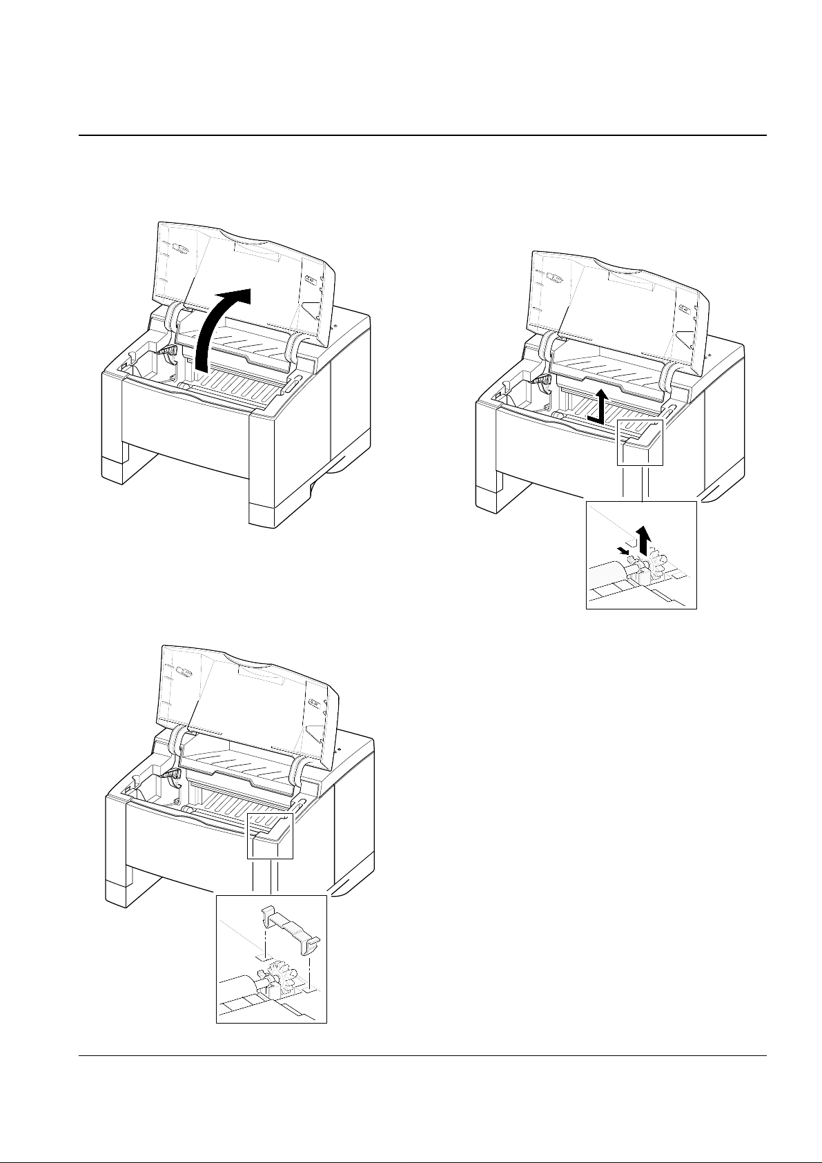
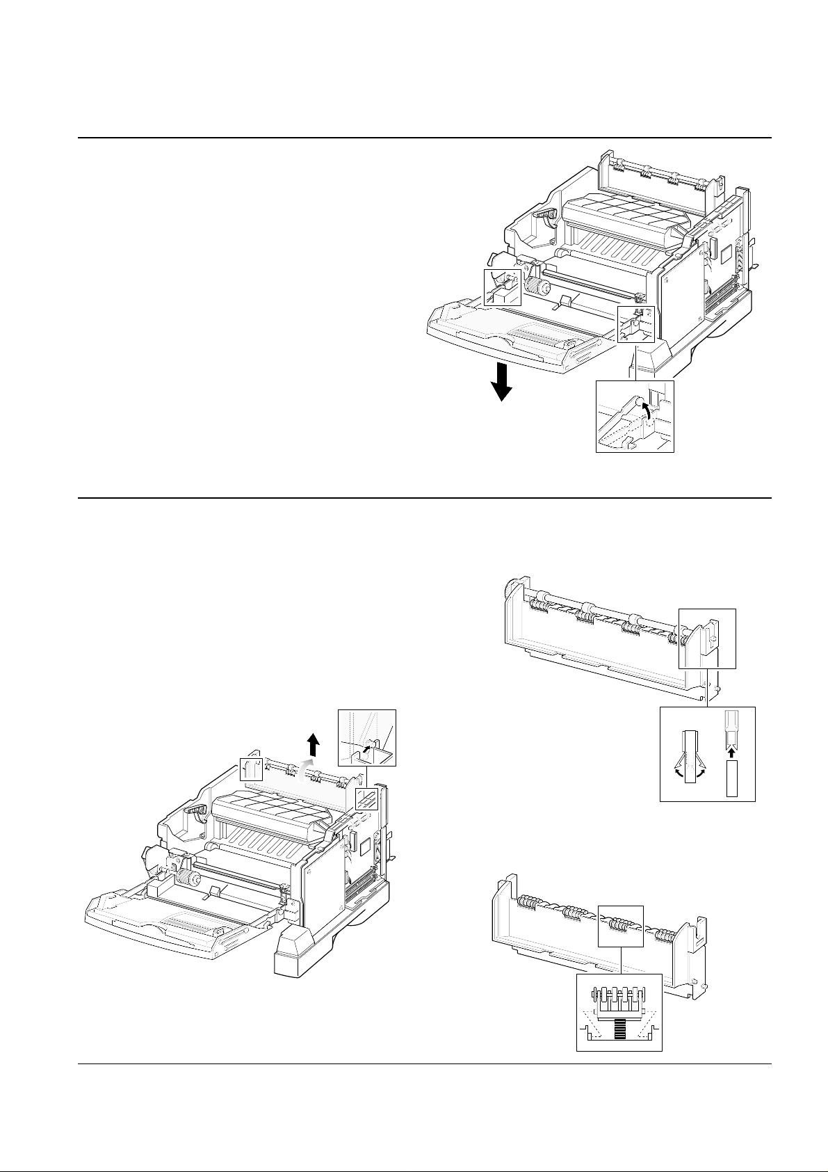
3-2 Transfer Roller
1. Open the printer cover.
3. Hold the cap at the both end of the roller, then
remove the roller.
2. Remove the cap.
Download Service Manual And Resetter Printer at http://printer1.blogspot.com
Disassembly and Reassembly
3-3Samsung Electronics
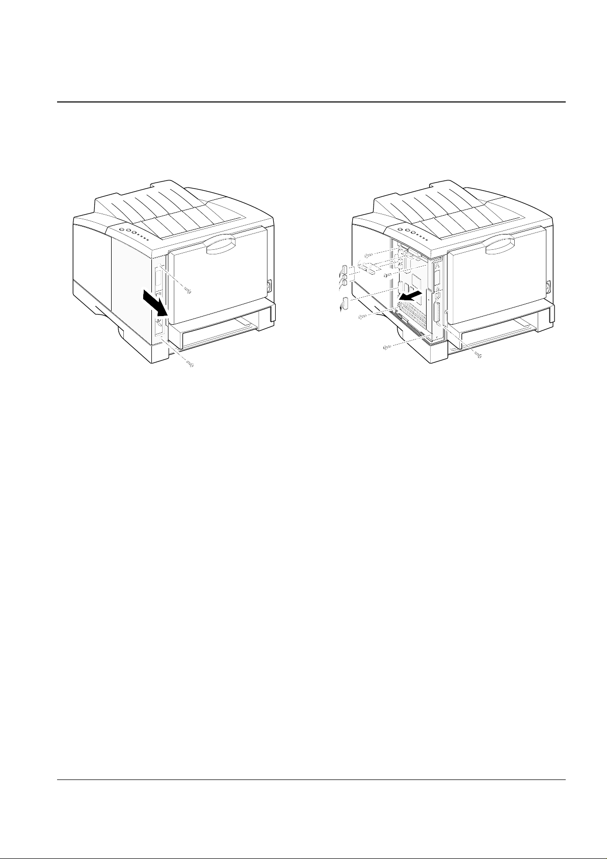
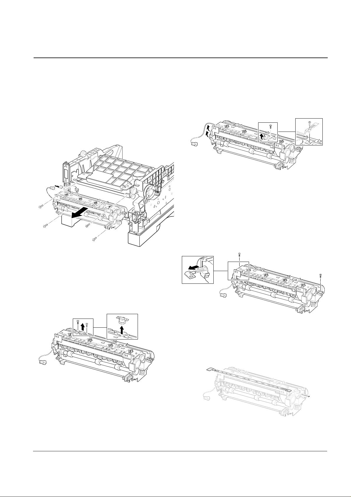
3-3 Controller Board
1. Remove two screws and remove the controller
board.
2. Remove five screws securing the board and
unplug all connectors, and then take the controller board out of the printer.
Download Service Manual And Resetter Printer at http://printer1.blogspot.com
Disassembly and Reassembly
3-4 Samsung Electronics
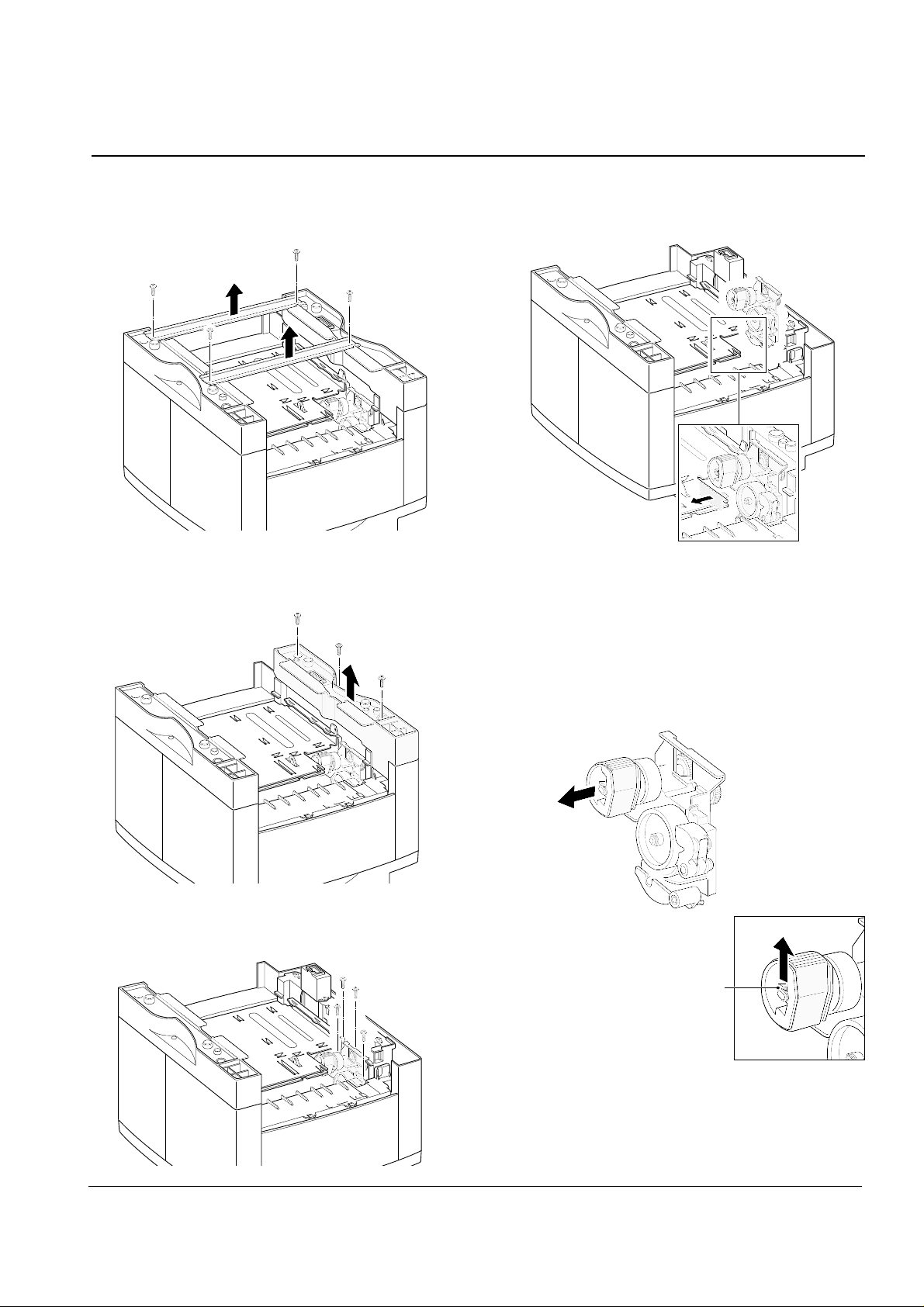
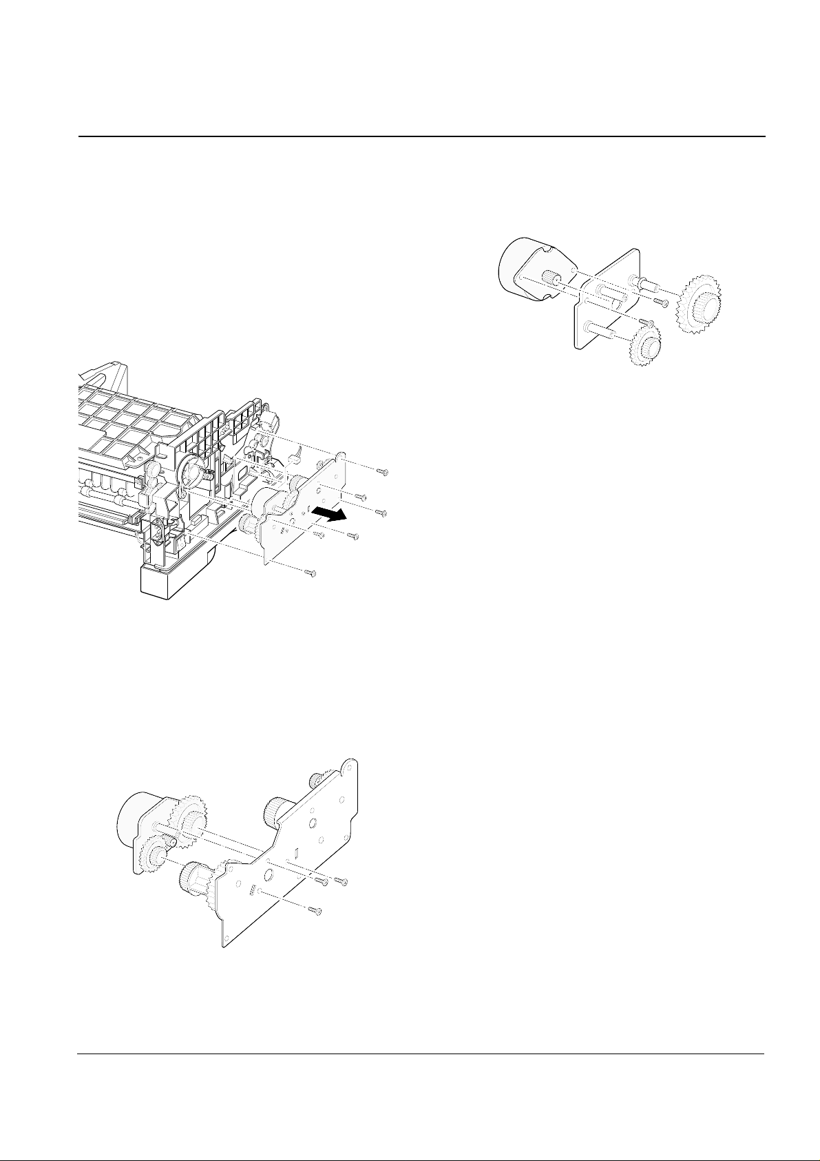
3-4 Pickup Assembly
1. Turn the printer upside down. Remove four
screws, then remove the bar cross bottom.
2. Remove three screws from the left base bracket,
and take the bracket out.
3. Remove four screws securing the pickup assembly.
4. Take the assembly out.
5. Check the pickup rubber wear. If the rubber is
heavily worn, replace it with a new one.
Squeeze this tab to
remove the rubber.
Push the solenoid if
you have difficulty to
remove the pickup
assembly.
Download Service Manual And Resetter Printer at http://printer1.blogspot.com
Disassembly and Reassembly
3-5Samsung Electronics
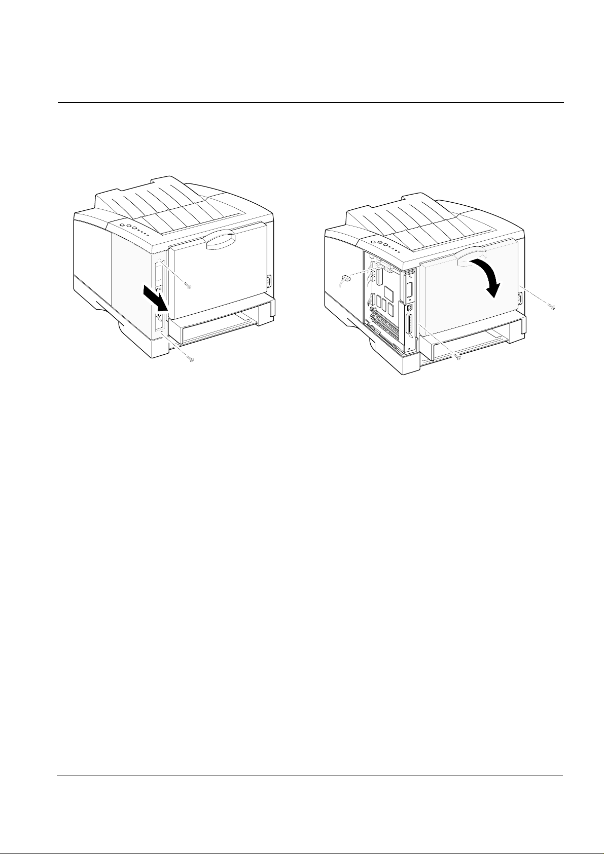
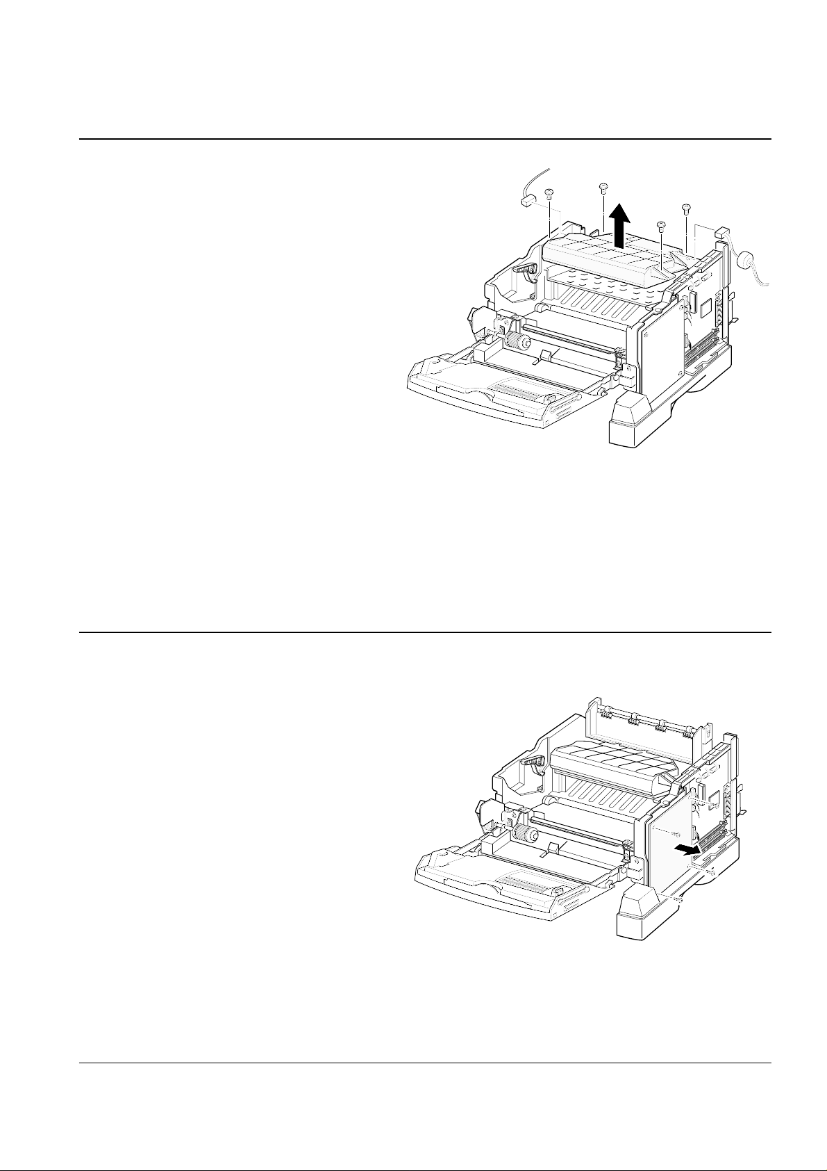
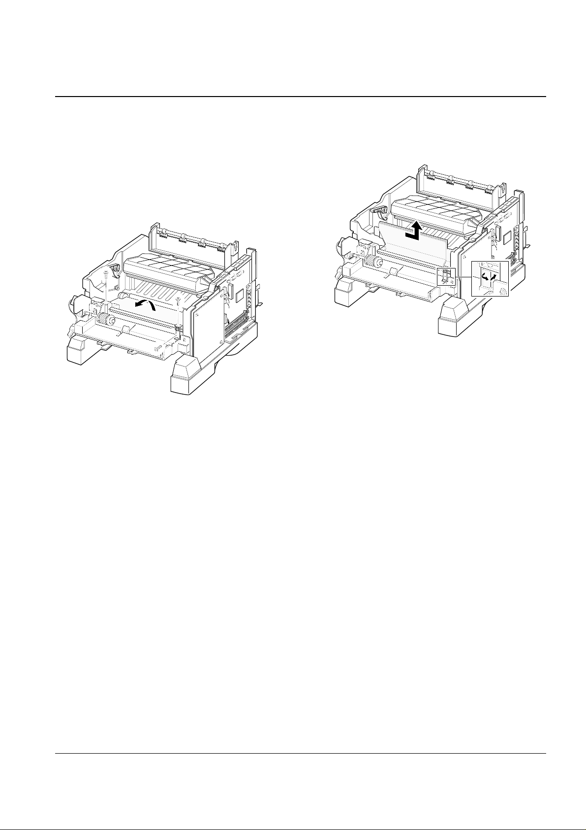
3-5 Main Cover
1. Remove two screws and remove the controller
board.
2. Remove two screws at the back of the printer
and unplug one connector from the board, then
open the rear cover.
Download Service Manual And Resetter Printer at http://printer1.blogspot.com
Disassembly and Reassembly
3-6 Samsung Electronics
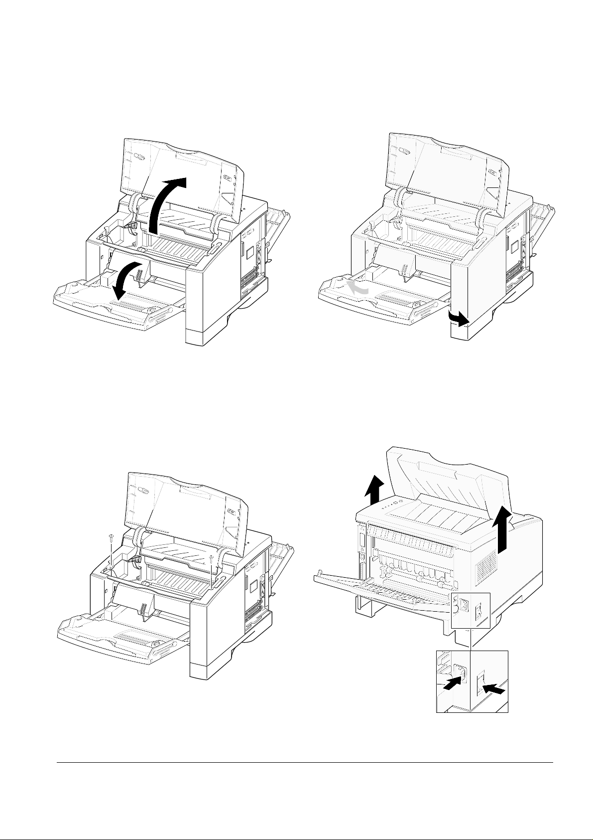
6. Remove two screws securing the main cover.
5. Open the printer cover, and open the MP tray.
8. Slide the main cover upward, out of the printer.
Note that the power
switch and the power
connecter are properly
released when you
remove the cover.
7. Unlatch the front ends of the cover.
Download Service Manual And Resetter Printer at http://printer1.blogspot.com
Disassembly and Reassembly
3-7Samsung Electronics
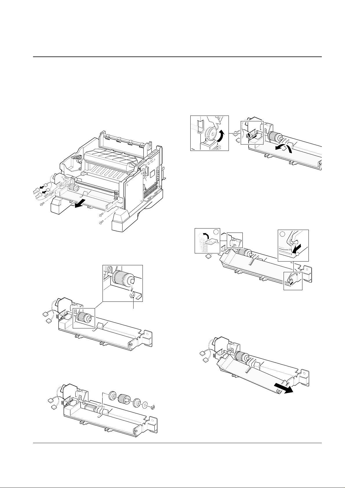
3-6 MP (Multi-Purpose) Tray
1. Before you remove the MP tray, you should
remove:
-Main Cover (see page 3-5)
2. Remove the stoppers securing the MP tray.
3-7 Exit Assembly
1. Before you remove the exit assembly, you should
remove:
-Main Cover (see page 3-5)
2. Remove the exit tray in the direction of arrow.
3. If you want to remove the roller shaft, unlatch
both ends of the shaft and take it out.
4. If you want to remove the exit roller, sqeeze the
bottom of the roller and take it out.
Download Service Manual And Resetter Printer at http://printer1.blogspot.com
Disassembly and Reassembly
3-8 Samsung Electronics
3-8 LSU
1. Before you remove the LSU, you should remove:
-Main Cover (see page 3-5)
-Exit assembly (see page above)
2. Remove four screws, and remove the LSU. Then
unplug two connectors from the LSU.
3-9 HVPS board
1. Before you remove the HVPS board, you should
remove:
-Main Cover (see page 3-5)
2. Remove four screws and take the HVPS board out.
Download Service Manual And Resetter Printer at http://printer1.blogspot.com
Disassembly and Reassembly
3-9Samsung Electronics
3-10 Drive Assembly
1. Before you remove the drive assembly, you
should remove:
-Main Cover (see page 3-5)
2. Remove six screws securing the drive assembly
from the gear bracket and unplug one connector
from the motor, and then take the drive assembly
out.
3. If you want to remove the motor from the drive
assembly, remove three gold screws securing the
motor assembly to the gear bracket.
4. Remove the motor assembly. Remove two screws
securing the motor to the motor bracket, then
take the motor out.
Download Service Manual And Resetter Printer at http://printer1.blogspot.com
Disassembly and Reassembly
3-10 Samsung Electronics
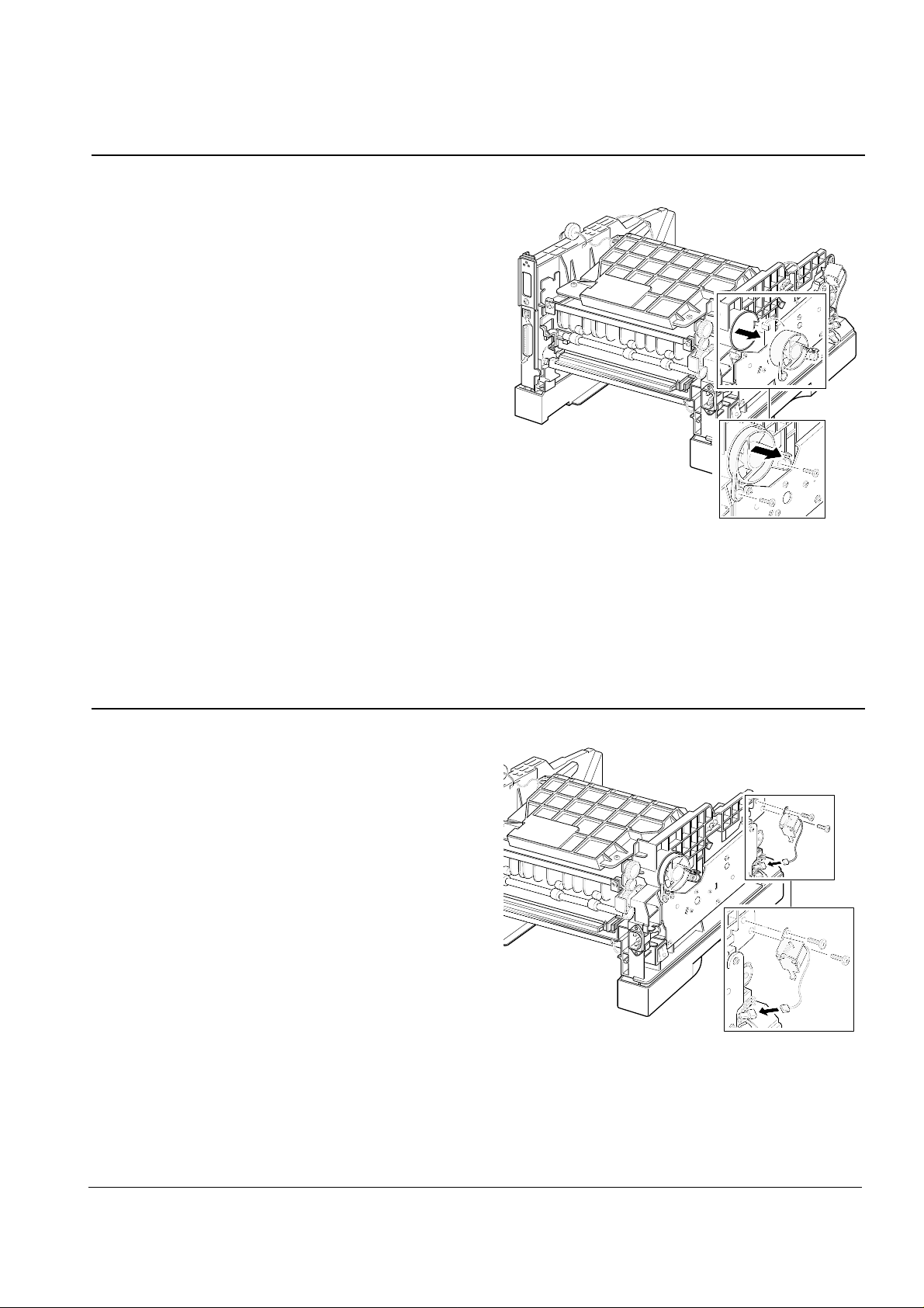
3-11 Fan
1. Before you remove the fan, you should remove:
-Main Cover (see page 3-5)
2. Remove two screws, and remove the fan. Then
unplug one connector.
3-12 Solenoid
1. Before you remove the solenoid, you should
remove:
-Main Cover (see page 3-5)
2. Remove two screws, and remove the solenoid.
Then unplug one connector.
Download Service Manual And Resetter Printer at http://printer1.blogspot.com
Disassembly and Reassembly
3-11Samsung Electronics
3-13 Fuser Assembly
1. Before you remove the fuser, you should remove:
-Main Cover (see page 3-5)
2. Remove four screws and unplug one connector,
and then remove the fuser assembly.
To remove the thermostat from the fuser assembly
Remove two screws and take the thermostat out.
To remove the thermistor from the fuser assembly :
Remove one screw, and release the wire from the
three holders, and then take the thermistor out.
To remove the halogen lamp from the fuser assembly :
Remove two screws and take the halogen lamp out
of the fuser assembly.
Note: When you reassemble the halogen lamp,
make sure that it is inserted into the slot
properly.
Download Service Manual And Resetter Printer at http://printer1.blogspot.com
Disassembly and Reassembly
3-12 Samsung Electronics
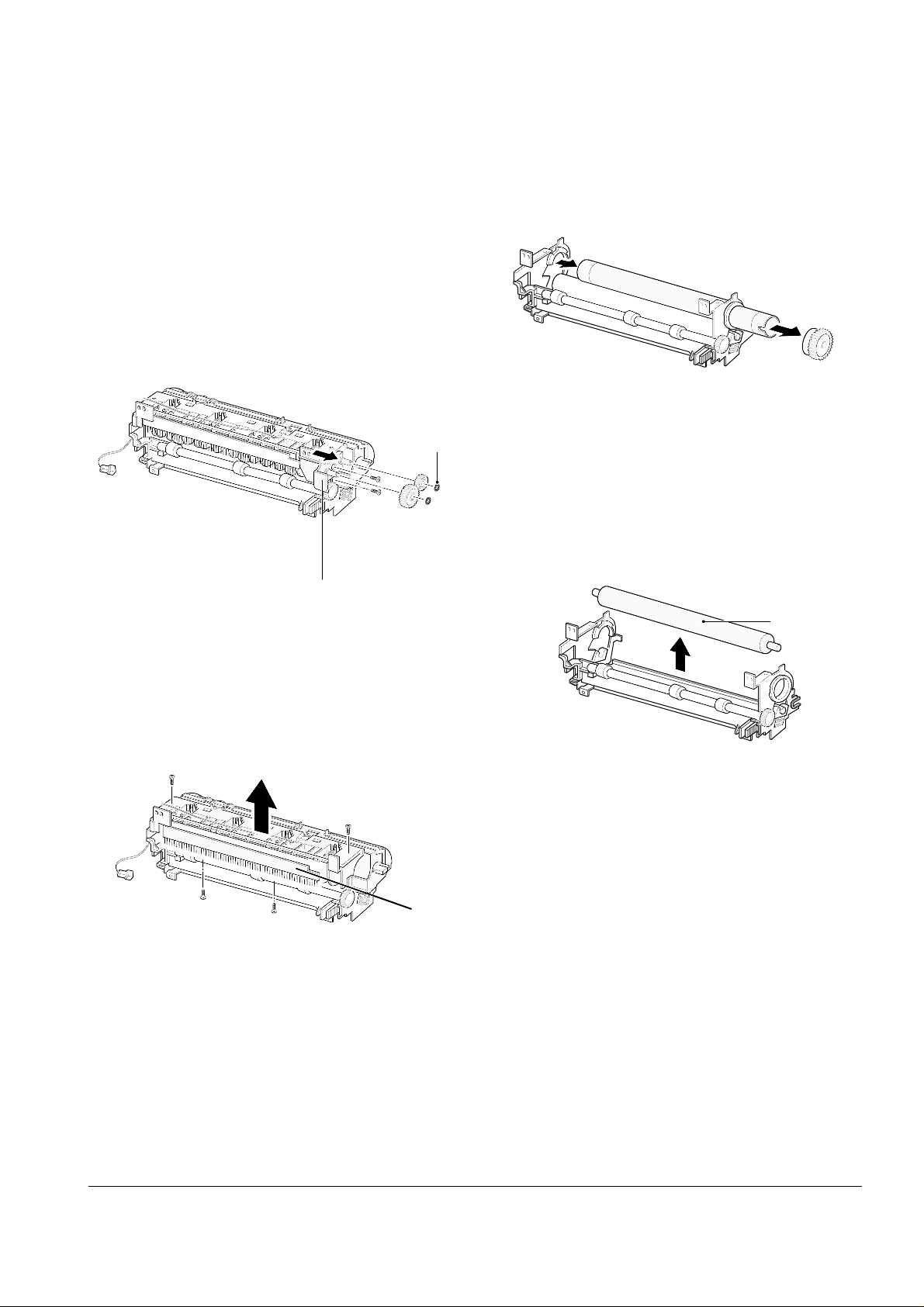
3. Remove two screws and take the cover fuser out.
4. Remove two screws and take the holder brush
ant out.
4. Remove the heat roller.
To remove the pressure roller from the fuser
assembly :
Remove the roller.
To remove the heat roller from the fuser assembly :
1. Remove the halogen lamp. (see page 3-11)
2. Remove two CS-rings and two gears. Then remove
two screws securing the BRKT gear fuser and take
the gear fuser out.
pressure roller
BRKT gear fuser
CS-ring
Holder brush ant
Download Service Manual And Resetter Printer at http://printer1.blogspot.com
Disassembly and Reassembly
3-13Samsung Electronics
3-14 Guide Feed
1. Before you remove the guide feed, you should
remove:
-Main Cover (see page 3-5)
2. Remove two screws and raise the guide feed in
the direction of arrow.
3. Remove the guide feed.
Download Service Manual And Resetter Printer at http://printer1.blogspot.com
Disassembly and Reassembly
3-14 Samsung Electronics
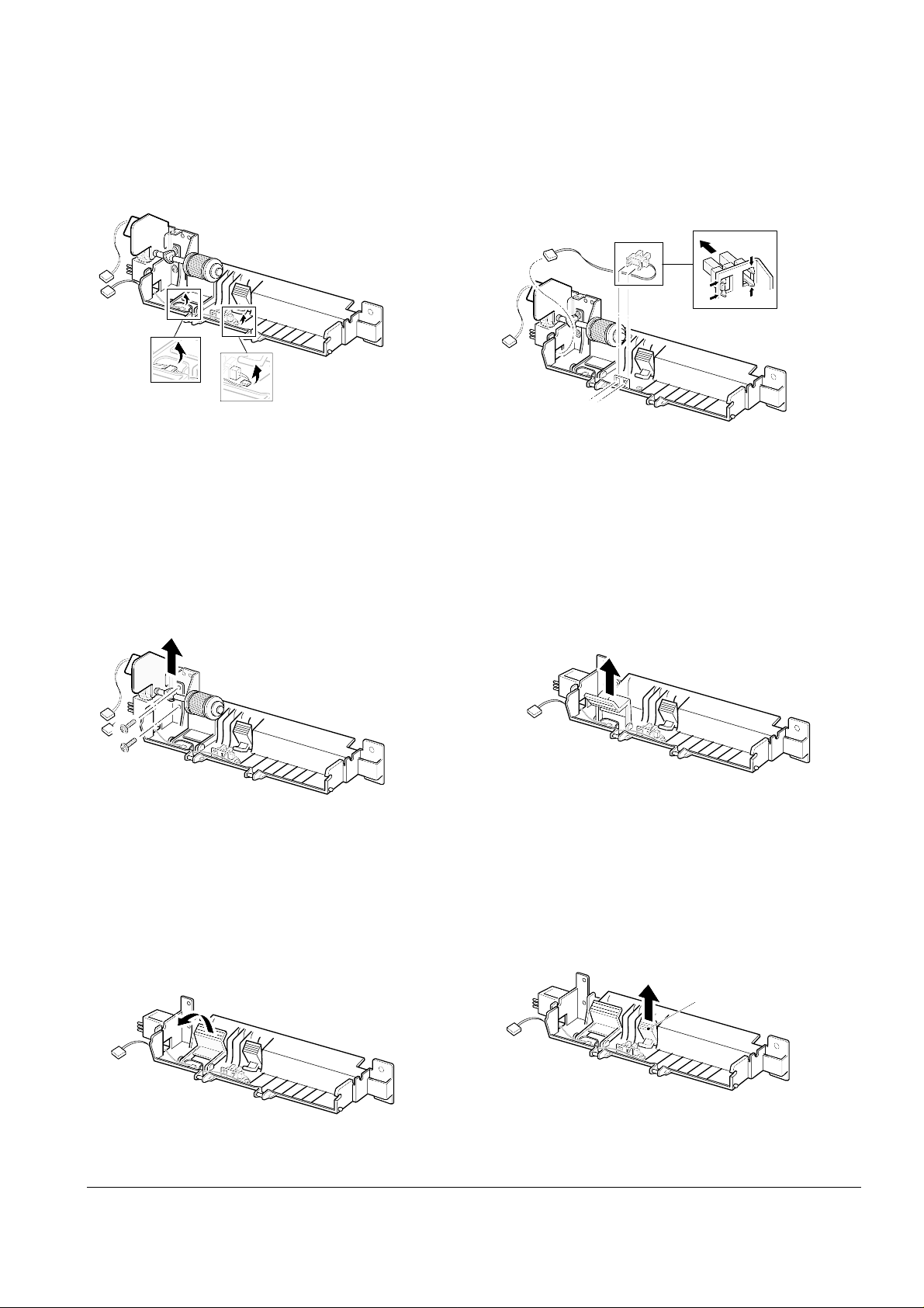
3-15 MPF Assembly and Miscellaneous on MPF Assembly
1. Before you remove the MPF assembly, you
should remove:
-Main Cover (see page 3-5)
2. Unplug two connectors and remove five screws,
and then take the MPF assembly out.
To replace the pickup roller :
1. Remove the e-ring.
2. Remove the roller.
To replace the nockup plate :
1. Turn the gear shown in the square in the direction of arrow to release the nockup plate.
2. Remove the spring , then release the right end of
the plate .
1
2
3. Remove the nockup plate.
e-ring
Download Service Manual And Resetter Printer at http://printer1.blogspot.com
Disassembly and Reassembly
3-15Samsung Electronics
To replace the Paper Empty (PE) sensor :
1. Release the wire from the two holders.
2. Unlatch the PE sensor, then take it out.
To replace the pickup holder and the Adjust End
MP:
1. Remove two screws and remove the MPT bracket.
2. Raise the pickup holder in the direction of
arrow.
3. Remove the pickup holder.
4. Remove the Adjust End MP
Adjust End MP
Download Service Manual And Resetter Printer at http://printer1.blogspot.com
Disassembly and Reassembly
3-16 Samsung Electronics
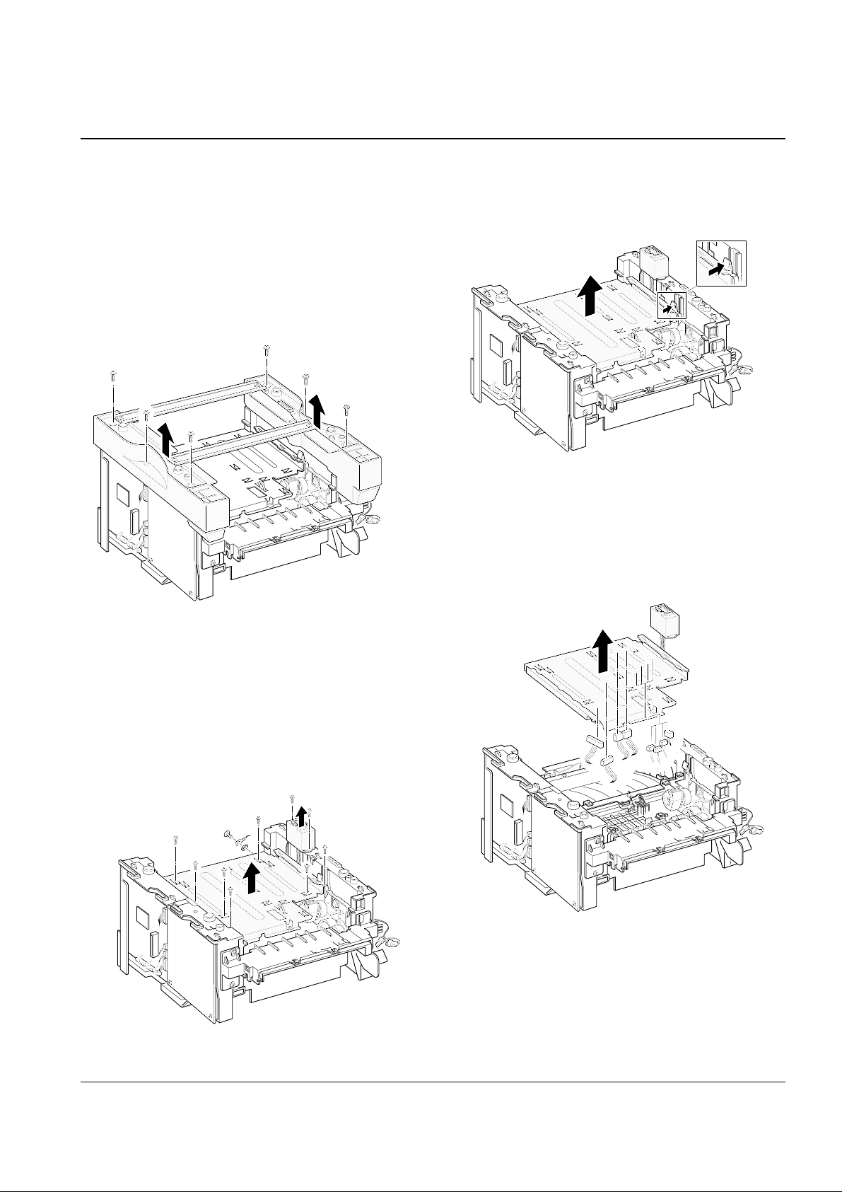
3-16 Engine Board and Miscellaneous
1. Before you remove the engine board, you should
remove:
-Main Cover (see page 3-5)
2. Remove six screws from the left and the right
base brackets and take them out.
4. While you push the latch to release the PCU
shield, take the PCU shield out of the printer.
3. Remove eight screws securing the PCU shield
and remove two screws securing the SCF connector, and then take the PCU shield out of the
printer.
5. Unplug all connectors from the PCU shield, and
remove the shield.
Download Service Manual And Resetter Printer at http://printer1.blogspot.com
Disassembly and Reassembly
3-17Samsung Electronics
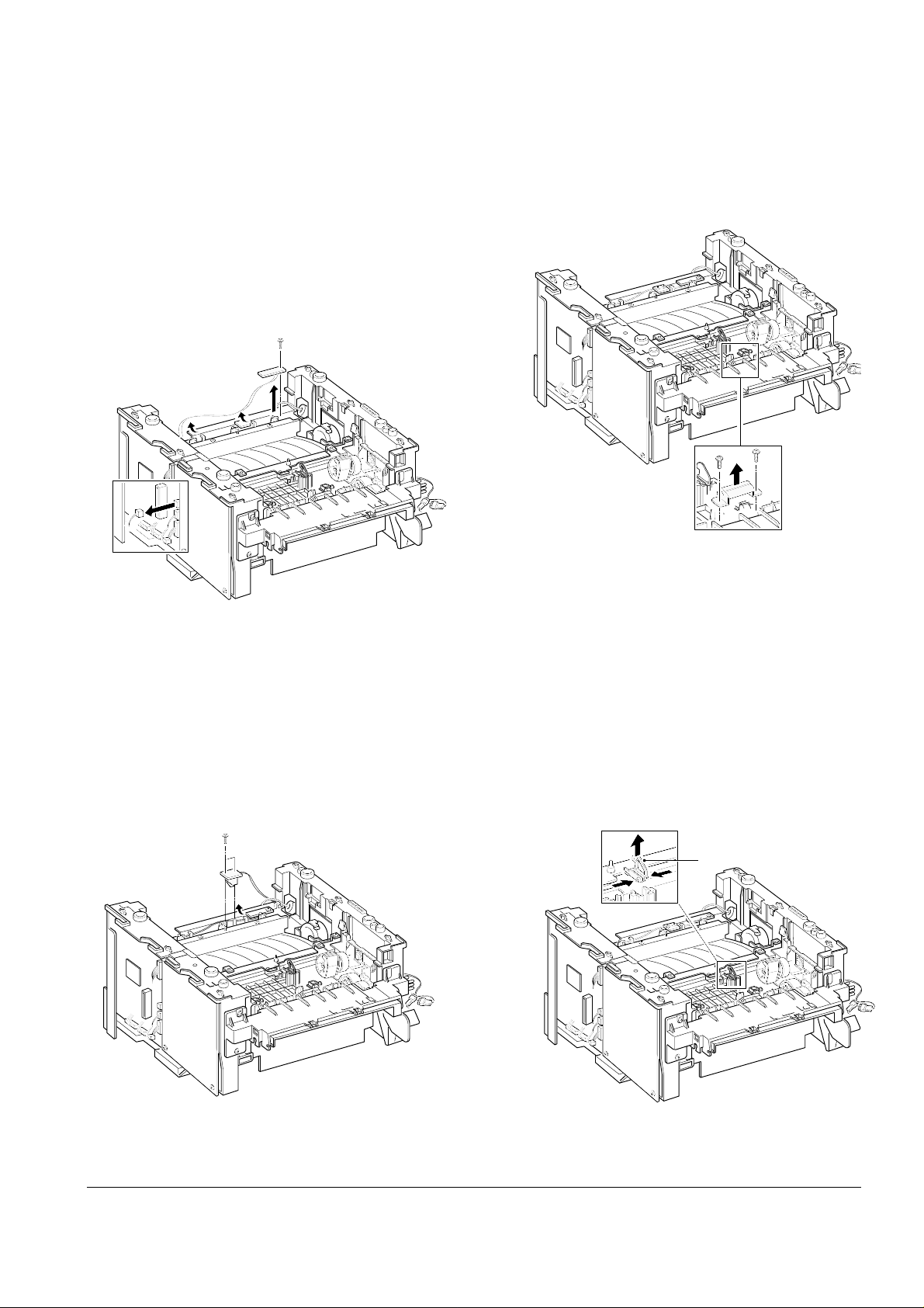
To replace the exit board :
Unplug one connector from the controller board
and remove one screw securing the board. Then
release the wire from two holders and take the
board out.
To replace the fuser sensor :
Remove two screws and take it out.
To replace the Cap sensor :
Remove two screws and take it out.
To replace the actuator empty :
Take the sensor out while you squeeze the both
ends of the sensor.
Actuator empty
Download Service Manual And Resetter Printer at http://printer1.blogspot.com
Disassembly and Reassembly
3-18 Samsung Electronics
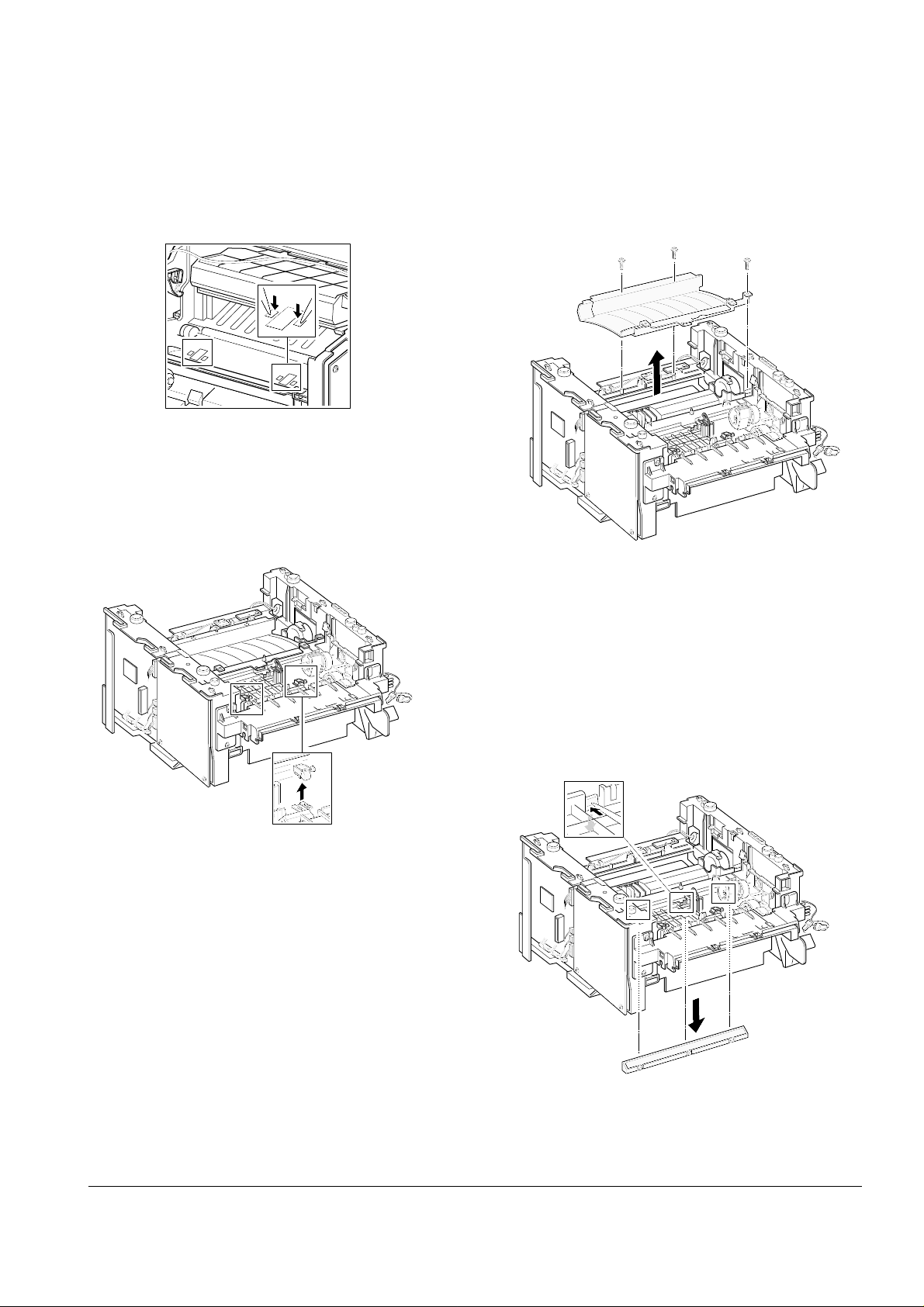
To replace the actuator feed
1. Turn the mechanism back and push down the
points as shown to unlatch the actuator feed.
2. Turn the unit over again, and remove the actuator feed.
To remove the transfer guide :
Remove three screws and take the guide out.
To replace the PTL ass’y
Release the three tabs latching the sensor using a
phillips screwdriver, then push the sensor down.
Download Service Manual And Resetter Printer at http://printer1.blogspot.com

Troubleshooting
4-1Samsung Electronics
4. Troubleshooting
4-1 DCU Control
In case of ML-6060,you can not use the DCU under ‘Diagnostic mode’
But, you can check set condition by status code
4-1-1 DCU Setup
1) Connect DCU to Controller Board Connector CN9 (4 pins)).
4-1-2 DCU Error Status Code
DCU error code will indicate malfunction area of the machine.
Display Error status
60 OPEN FUSER ERROR
62 LOW HEAT ERROR
68 OVER HEAT ERROR
64 COVER OPEN ERROR
70 NO PAPER or NO CASSETTE
71 PAPER JAM 0
72 PAPER JAM 1
73 PAPER JAM 2
95 LSU NOT READY
Download Service Manual And Resetter Printer at http://printer1.blogspot.com
4-1-3 Error Solution
Display Solution
60, 62, 68 1. Measure the resistance of the AC connector on the Fuser. Normal resistance is 2-4 ohms
for 110V, 6-8 ohms for 220V.
2. Check if the fuser lamp works properly.
3. Measure the resistance at Q7 on the engine board. If abnormal, replace U503,CN502,
70 1. Make sure that paper is loaded in the cassette.
2. Replace U555 sensor (photo interrupter).
3. Replace U7 on controller board.
71 1. Make sure that paper is loaded in the cassette.
2. Check for pick-up unit. If it is heavily worn, replace it with new one.
3. Replace U554 sensor.
4. Check if the feed clutch works properly.
5. If abnormal, replace the feed clutch or Q3 on the Engine board .
72, 73 1. Make sure that the paper being used meets the specification.
2. Check if there is a paper jam in the fuser.
3. Replace U554 on the engine board or exits ensor on the frame.
4. Check the fuser roller for any dirt. If dirty, clean the roller.
95 1. Check for CN11,CN6 on the Controller board.
2. Replace U5,OSC1 on the Engine board.
3. Replace LSU.
Troubleshooting
4-2 Samsung Electronics
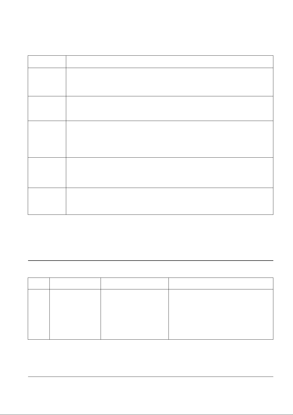
4-2 Abnormal Image Printing and Defective Roller
If abnormal image prints periodically, check the parts shown below.
No Roller Abnormal image period Kind of abnormal image
1 OPC Drum 95.6mm White spot
2 Charge Roller 38.5mm Black spot
3 Supply Roller 45.3mm Horizontal density band
4 Develop Roller 47.1mm Horizontal density band
5 Transfer Roller 56.1mm Black side contamination/transfer fault
6 Heat Roller 69.3mm Black spot and fuser ghost
7 Pressure Roller 72.5mm Black side contamination
Download Service Manual And Resetter Printer at http://printer1.blogspot.com
 Loading...