

Page 1
DIGITAL LASER PRINT
ML-3560 Series
ML-3560/XAA
Basic Model :ML-3560
Manual
SERVICE
DIGITAL LASER PRINT CONTENTS
1. Precautions
2. Reference Information
3. Specifications
4. Summary of product
5. Disassembly and Reassembly
6. Alignment and Adjustments
7. Troubleshooting
8. Exploded Views and Parts List
9. Block Diagram
10. Connection Diagram
11. Schematic Diagram
Page 2
Precautions
Samsung Electronics
Service Manual
1-1
1
1
1. Precautions
In order to prevent accidents and to prevent damage to the equipment please read the precautions listed
below carefully before servicing the printer and follow them closely.
1.1 Safety Warning
(1) Only to be serviced by appropriately qualified service engineers.
High voltages and lasers inside this product are dangerous. This printer should only be serviced by a suitably
trained and qualified service engineer.
(2) Use only Samsung replacement parts
There are no user serviceable parts inside the printer. Do not make any unauthorized changes or
additions to the printer , these could cause the printer to malfunction and create electric shock or fire hazards.
(3) Laser Safety Statement
The Printer is certified in the U.S. to conform to the requirements of DHHS 21 CFR, chapter 1 Subchapter J for
Class 1(1) laser products, and elsewhere, it is certified as a Class I laser product
conforming to the requirements of IEC 825. Class I laser products are not considered to be hazardous. The
laser system and printer are designed so there is never any human access to laser radiation above a Class I
level during normal operation, user maintenance, or prescribed service condition.
Warning >> Never operate or service the printer with the protective cover removed from Laser/Scanner assembly. The
reflected beam, although invisible, can damage your eyes. When using this product, these basic safety
pre-cautions should always be followed to reduce risk of fire, electric shock, and injury to persons.
CAUTION - INVISIBLE LASER RADIATION
WHEN THIS COVER OPEN.
DO NOT OPEN THIS COVER.
VORSICHT - UNSICHTBARE LASERSTRAHLUNG,
WENN ABDECKUNG GEFFNET.
NICHT DEM STRAHL AUSSETZEN.
ATTENTION - RAYONNEMENT LASER INVISIBLE EN CAS
D OUVERTURE. EXPOSITION DANGEREUSE
AU FAISCEAU.
ATTENZIONE - RADIAZIONE LASER INVISIBILE IN CASO DI
APERTURA. EVITARE L ESPOSIZIONE AL
FASCIO.
PRECAUCION - RADIACION LASER IVISIBLE CUANDO SE ABRE.
EVITAR EXPONERSE AL RAYO.
ADVARSEL. - USYNLIG LASERSTRLNING VED BNING, N R
SIKKERHEDSBRYDERE ER UDE AF FUNKTION.
UNDG UDSAETTELSE FOR STR LNING.
ADVARSEL. - USYNLIG LASERSTRLNING N R DEKSEL
PNES. STIRR IKKE INN I STR LEN.
UNNG EKSPONERING FOR STR LEN.
VARNING - OSYNLIG LASERSTRLNING N R DENNA DEL
R PPNAD OCH SP RREN R URKOPPLAD.
BETRAKTA EJ STR LEN. STR LEN R FARLIG.
VARO! - AVATTAESSA JA SUOJALUKITUS OHITETTAESSA
OLET ALTTIINA N KYM TT M LLE LASERS TEILYLLE L KATSO STEESEEN.
Page 3

Samsung Electronics
Service Manual
Precautions
1-2
1.2 Caution for safety
1.2.1 Toxic material
This product contains toxic materials that could cause illness if ingested.
(1) If the LCD control panel is damaged it is possible for the liquid inside to leak. This liquid is toxic. Contact with the skin
should be avoided, wash any splashes from eyes or skin immediately and contact your doctor. If the liquid gets into
the mouth or is swallowed see a doctor immediately.
(2) Please keep toner cartridges away from children. The toner powder contained in the toner cartridge may be harmful
and if swallowed you should contact a doctor.
1.2.2 Electric Shock and Fire Safety Precautions
Failure to follow the following instructions could cause electric shock or potentially cause a fire.
(1) Use only the correct voltage, failure to do so could damage the printer and potentially cause a fire or electric
shock.
(2) Use only the power cable supplied with the printer. Use of an incorrectly specified cable could cause the cable
to overheat and potentially cause a fire.
(3) Do not overload the power socket, this could lead to overheating of the cables inside the wall and could lead to
a fire.
(4) Do not allow water or other liquids to spill into the printer, this can cause electric shock. Do not allow paper
clips, pins or other foreign objects to fall into the printer these could cause a short circuit leading to an electric
shock or fire hazard..
(5) Never touch the plugs on either end of the power cable with wet hands, this can cause electric shock. When
servicing the printer remove the power plug from the wall socket.
(6) Use caution when inserting or removing the power connector. The power connector must be inserted com-
pletely otherwise a poor contact could cause overheating possibly leading to a fire. When removing the power
connector grip it firmly and pull.
(7) Take care of the power cable. Do not allow it to become twisted, bent sharply round corners or other wise
damaged. Do not place objects on top of the power cable. If the power cable is damaged it could overheat and
cause a fire or exposed cables could cause an electric shock. Replace a damaged power cable immediately,
do not reuse or repair the damaged cable. Some chemicals can attack the coating on the power cable,
weakening the cover or exposing cables causing fire and shock risks.
(8) Ensure that the power sockets and plugs are not cracked or broken in any way. Any such defects should be
repaired immediately. Take care not to cut or damage the power cable or plugs when moving the machine.
(9) Use caution during thunder or lightening storms. Samsung recommends that this machine be disconnected
from the power source when such weather conditions are expected. Do not touch the machine or the power
cord if it is still connected to the wall socket in these weather conditions.
(10) Avoid damp or dusty areas, install the printer in a clean well ventilated location. Do not position the machine
near a humidifier. Damp and dust build up inside the machine can lead to overheating and cause a fire.
(11) Do not position the printer in direct sunlight. This will cause the temperature inside the printer to rise possibly
leading to the printer failing to work properly and in extreme conditions could lead to a fire.
(12) Do not insert any metal objects into the machine through the ventilator fan or other part of the casing, it could
make contact with a high voltage conductor inside the machine and cause an electric shock.
Page 4

Precautions
Samsung Electronics
Service Manual
1-3
1.2.3 Handling Precautions
The following instructions are for your own personal safety, to avoid injury and so as not to damage the printer
(1) Ensure the printer is installed on a level surface, capable of supporting its weight. Failure to do so could cause
the printer to tip or fall.
(2) The printer contains many rollers, gears and fans. Take great care to ensure that you do not catch your fingers,
hair or clothing in any of these rotating devices.
(3) Do not place any small metal objects, containers of water, chemicals or other liquids close to the printer which if
spilled could get into the machine and cause damage or a shock or fire hazard.
(4) Do not install the machine in areas with high dust or moisture levels, beside on open window or close to a
humidifier or heater. Damage could be caused to the printer in such areas.
(5) Do not place candles, burning cigarettes, etc on the printer, These could cause a fire.
1.2.4 Assembly / Disassembly Precautions
Replace parts carefully, always use Samsung parts. Take care to note the exact location of parts and also
cable routing before dismantling any part of the machine. Ensure all parts and cables are replaced correctly.
Please carry out the following procedures before dismantling the printer or replacing any parts.
(1) Check the contents of the machine memory and make a note of any user settings. These will be erased if the
mainboard or network card is replaced.
(2) Ensure that power is disconnected before servicing or replacing any electrical parts.
(3) Disconnect printer interface cables and power cables.
(4) Only use approved spare parts. Ensure that part number, product name, any voltage, current or temperature
rating are correct.
(5) When removing or re-fitting any parts do not use excessive force, especially when fitting screws into plastic.
(6) Take care not to drop any small parts into the machine.
(7) Handling of the OPC Drum
- The OPC Drum can be irreparably damaged if it exposed to light.
Take care not to expose the OPC Drum either to direct sunlight or to fluorescent or incandescent room
lighting. Exposure for as little as 5 mins can damage the surface’s photoconductive properties and will result
in print quality degradation. Take extra care when servicing the printer. Remove the OPC Drum and store it in
a black bag or other lightproof container. T ake care when working with the covers(especially the top cover)
open as light is admitted to the OPC area and can damage the OPC Drum.
- Take care not to scratch the green surface of OPC Drum Unit.
If the green surface of the Drum Cartridge is scratched or touched the print quality will be compromised.
Page 5
Samsung Electronics
Service Manual
Precautions
1-4
1.2.5 Disregarding this warning may cause bodily injury
(1) Be careful with the high temperature part.
The fuser unit works at a high temperature. Use caution when working on the printer. Wait for the fuser to cool
down before disassembly.
(2) Do not put finger or hair into the rotating parts.
When operating a printer, do not put hand or hair into the rotating parts (Paper feeding entrance, motor, fan,
etc.). If do, you can get harm.
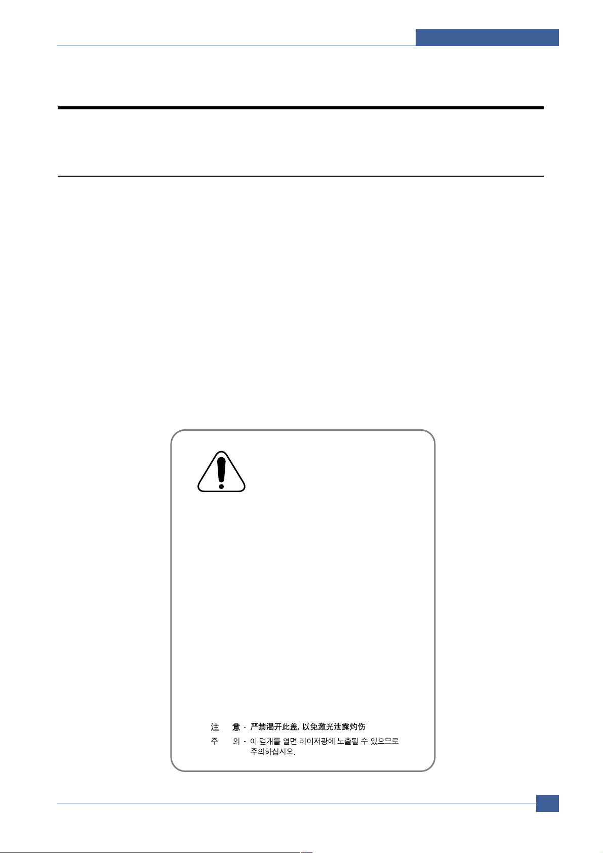
(3) When you move the printer.
This printer weighs 21kg including toner cartridge and cassette. Use safe lifting and handling techniques. Use
the lifting handles located on each side of the machine. Back injury could be caused if you do not lift carefully.
(4) Ensure the printer is installed safely.
The printer weighs 21Kg, ensure the printer is installed on a level surface, capable of supporting its weight.
Failure to do so could cause the printer to tip or fall possibly causing personal injury or damaging the printer.
(5) Do not install the printer on a sloping or unstable surface. After installation, double check that the printer is stable.
Page 6

Precautions
Samsung Electronics
Service Manual
1-5
1.3 ESD Precautions
Certain semiconductor devices can be easily damaged by static electricity . Such components are commonly called
“Electrostatically Sensitive (ES) Devices”, or ESDs. Examples of typical ESDs are: integrated circuits, some field
effect transistors, and semiconductor “chip” components.
The techniques outlined below should be followed to help reduce the incidence of component damage caused by
static electricity.
Caution >>Be sure no power is applied to the chassis or circuit, and observe all other safety precautions.
1. Immediately before handling a semiconductor component or semiconductor-equipped assembly, drain off any
electrostatic charge on your body by touching a known earth ground. Alternatively , employ a commercially available wrist strap device, which should be removed for your personal safety reasons prior to applying power to the
unit under test.
2. After removing an electrical assembly equipped with ESDs, place the assembly on a conductive surface, such as
aluminum or copper foil, or conductive foam, to prevent electrostatic charge buildup in the vicinity of the assembly .
3. Use only a grounded tip soldering iron to solder or desolder ESDs.
4. Use only an “anti-static” solder removal device. Some solder removal devices not classified as “anti-static” can
generate electrical charges sufficient to damage ESDs.
5. Do not use Freon-propelled chemicals. When sprayed, these can generate electrical charges sufficient to damage ESDs.
6. Do not remove a replacement ESD from its protective packaging until immediately before installing it. Most
replacement ESDs are packaged with all leads shorted together by conductive foam, aluminum foil, or a comparable conductive material.
7. Immediately before removing the protective shorting material from the leads of a replacement ESD, touch the protective material to the chassis or circuit assembly into which the device will be installed.
8. Maintain continuous electrical contact between the ESD and the assembly into which it will be installed, until completely plugged or soldered into the circuit.
9. Minimize bodily motions when handling unpackaged replacement ESDs. Normal motions, such as the brushing
together of clothing fabric and lifting one’s foot from a carpeted floor, can generate static electricity sufficient to
damage an ESD.
Page 7
Reference Information
Samsung Electronics
Service Manual
2-1
2
2
2. Reference Information
This chapter contains the tools list, list of abbreviations used in this manual, and a guide to the
location space required when installing the printer. A definition of tests pages and Wireless
Network information definition is also included.
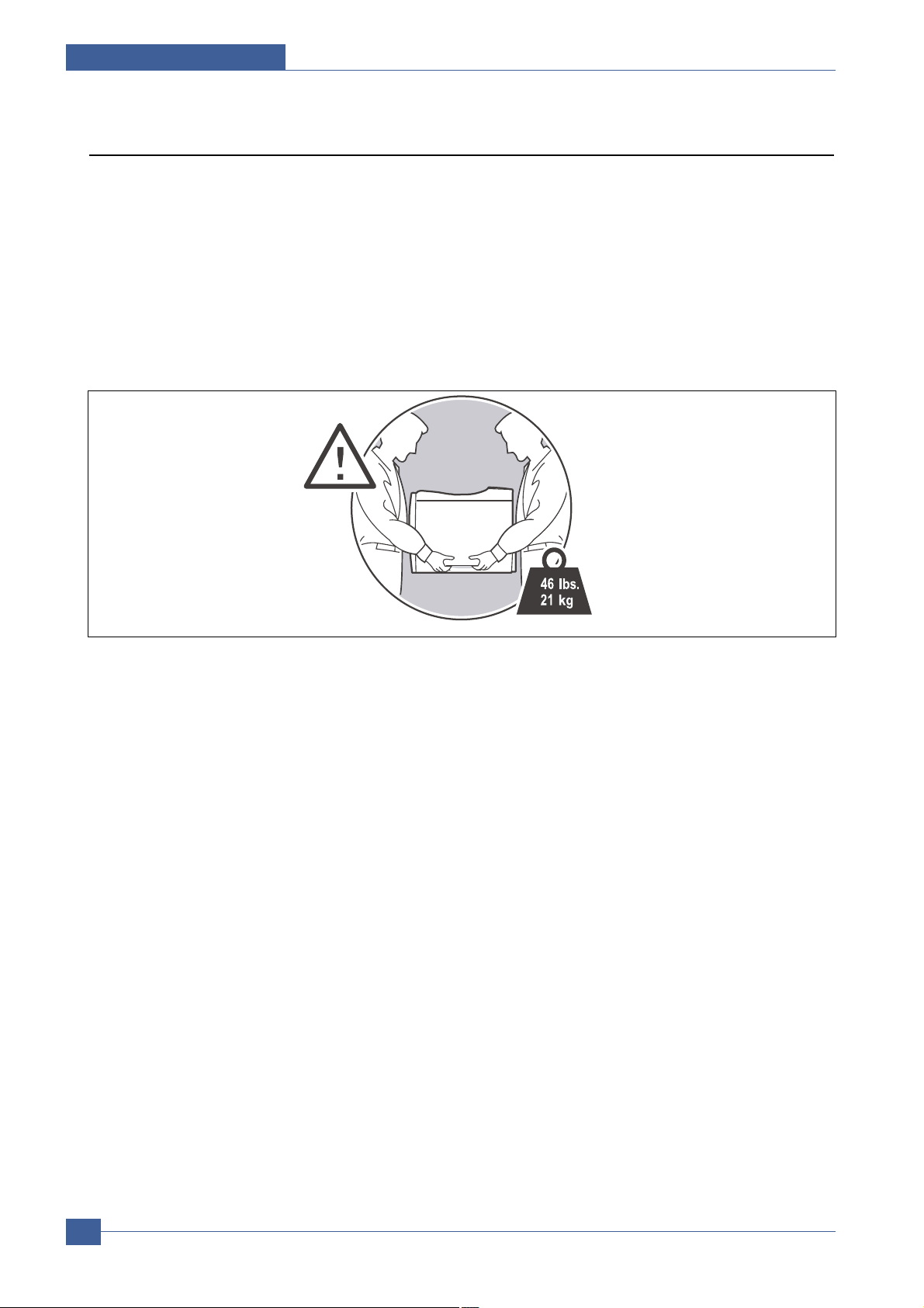
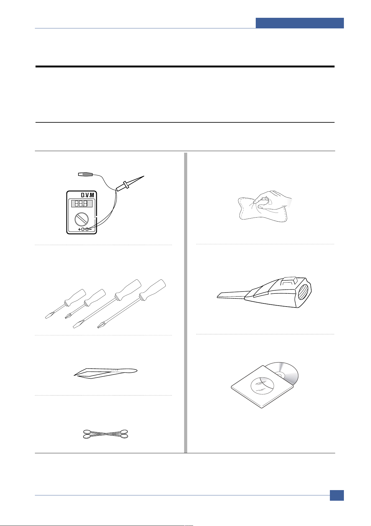
2.1 Tool for Troubleshooting
The following tools are recommended safe and easy troubleshooting as described in this service manual.
• DVM (Digital Volt Meter)
Standard : Indicates more than 3 digits.
• Driver
Standard : "-" type, "+" type (M3 long, M3 short, M2
long, M2 short).
• Tweezers
Standard : For general home use, small type.
• Cotton Swab
Standard : For general home use, for medical service.
• Cleaning Equipments
Standard : An IPA(Isopropyl Alcohol)dry wipe tissue or
a gentle neutral detergent and lint-free cloth.
• Vacuum Cleaner
• Software (Driver) installation CD ROM
Page 8

Service Manual
Reference Information
2-2
Samsung Electronics
2.2 Acronyms and Abbreviations(1)
The table below explains the abbreviations and acronyms used in this service manual. Where abbreviations
or acronyms are used in the text please refer to this table.
Abbreviations Explanation
AP Access Point
AC Alternating Current
APC Auto Power Control
ASIC Application Specific Integrated Circuit
ASSY assembly
BIOS Basic Input Output System
BLDC Brush-less Direct Current
CMOS Complementary Metal Oxide Semiconductor
CN connector
CON connector
CPU Central Processing Unit
dB decibel
dBA decibel A
dBM decibel milliwatt
DC direct current
DCU Diagnostic Control Unit
DPI Dot Per Inch
DRAM Dynamic Random Access Memory
DVM Digital Voltmeter
ECP Enhanced Capability Port
EDC Embedded Diagnostic control
EEPROM Electronically Erasable Programmable Read Only Memory
EMI Electro Magnetic Interference
EP electrophotographic
EPP Enhanced Parallel Port
FPOT First Printout Time
F/W firmware
GDI graphics device interface
GND ground
HBP Host Based Printing
HDD Hard Disk Drive
H/H High temperature and high marshy place
HV high voltage
HVPS High V oltage Power Supply
I/F interface
I/O Input and Output
IC integrated circuit
IDE Intelligent Drive electronics or Imbedded Drive Electronics
Page 9

Reference Information
Samsung Electronics
Service Manual
2-3
Acronyms and Abbreviations(2)
Abbreviations Explanation
IEEE Institute of Electrical and Electronics Engineers. Inc
IP A Isopropy Alcohol
IPM Images Per Minute
LAN local area network
lb pound(s)
LBP Laser Beam Printer
LCD Liquid Crystal Display
LED Light Emitting Diode
L/L Low temperature and low marshy place
LSU Laser Scanning Unit
MB megabyte
MHz megahertz
MPF Multi Purpose Feeder
NIC Network Interface Card
N/N Normal temperature and normal marshy place
NVRAM nonvolatile random access memory
OPC Organic Photo Conductor
OP Operation Panel Equipment
PBA Printed Board Assembly
PCL Printer Command Language , Printer Control Language
PDL Page Discription Language
PPM Page Per Minute
PPS Pulse Per Second
PS Post Script
PTL Pre-Transfer Lamp
PWM Pulse Width Modulation
Q-PID Quick Printer Initiating Device
Q ty quantity
RAM Random Access Memory
ROM Read Only Memory
SCF Second Cassette Feeder
SMPS Switching Mode Power Supply
SPGP Samsung Printer Graphic Processor
SPL Samsung Printer Language
Spool Simultaneous Peripheral Operation Online
SW switch
sync synchronous or synchronization
USB Universal Serial Bus
WECA Wireless Ethernet Compatibility Alliance
Page 10
Service Manual
Reference Information
2-4
Samsung Electronics
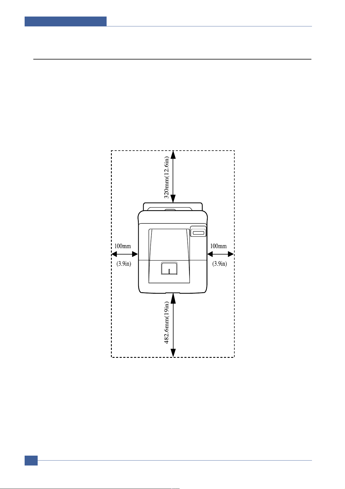
2.3 Select a location for the printer
• Leave enough room to open the printer trays, covers, and allow for proper ventilation. (see diagram
below)
• Provide the proper environment :
- Afirm, level surface
- Away from the direct airflow of air conditioners, heaters, or ventilators
- Free of extreme fluctuations of temperature, sunlight, or humidity
- Clean, dry, and free of dust
Page 11
Reference Information
Samsung Electronics
Service Manual
2-5
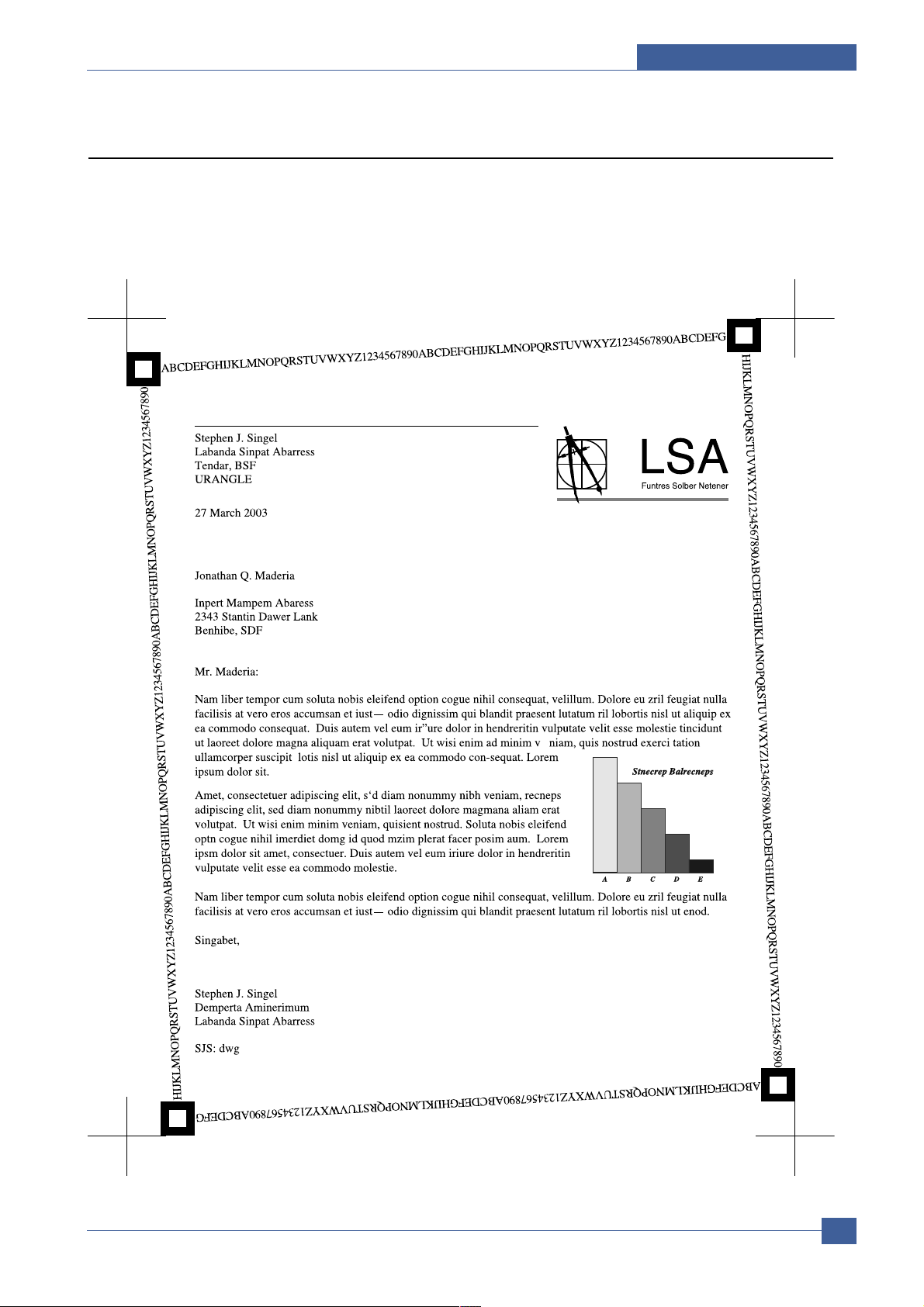
2.4 Sample Tests Patterns
The sample patterns shown below are the standard test patterns used in the factory.
The life of the toner cartridge, developer cartridge and printing speed are measured with the pattern shown
below (5%). The A4 ISO 19752 standard pattern samples are reproduced reduced to 70% of the actual A4
size.
Page 12
Service Manual
Reference Information
2-6
Samsung Electronics
2.5 Wireless LAN
• This product can be used with a wireless LAN (Option)
- The wireless LAN function uses radio technology, instead of using LAN cable, to connect to an
access point for printing.
- For a wireless LAN connection in Infrastructure mode an AP is needed, (purchased separately)
- For a wireless LAN connection in Ad-Hoc mode an appropriate Wireless I/F card is required fitted
to a computer, (purchased separately)
- It is possible to use a wireless LAN connection with wired LAN.
- If an AP is installed in an office or at home, the wireless LAN function can be simply configured
and used.
• Types of desk top PC (or Lap top) that uses the wireless LAN.
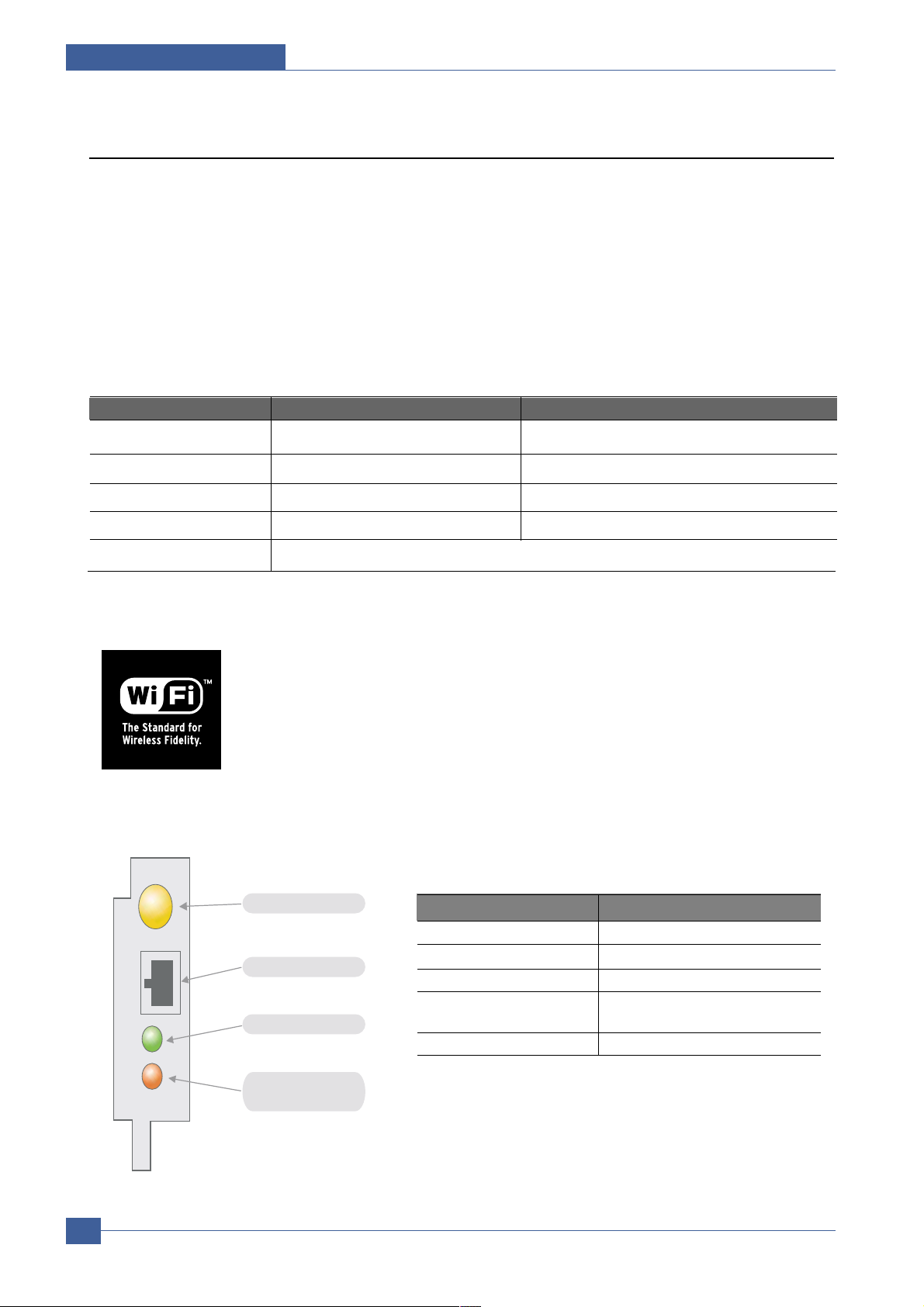
• About the certificated mark of Wi-Fi
TM
- Wi-FiTMis a registered trademark of the WECA (Wireless Ethernet Compatibility
Alliance). Over 50 wireless LAN companies are member of this organisation. Most of
the main wireless networking companies are attending including such companies as
Lucent Technologies, Cisco, Intel/Symbol, 3Com, Enterasys (Cabletron), Compaq,
IBM, Nokia, Dell, Philips, Samsung Electronics, Sony, Intersil, etc.. This mark certifies
mutual compatibility amongst the product of these companies. Wi-FiTM(IEEE 802.1) is
certified as a standard of the wireless LAN market.
• LED Condition and Status
Division Basic type Recommend type
CPU Over PENTIUM 233M PENTIUM 300MHz
MEMORY Over 64MB Over 128MB
VIDEO CARD Over 800X600 Over 1024X768
OS Over WINDOWS 98 Over WINDOWS ME
INTERFACE CARD A product has a certificated mark of Wi-Fi
TM
LED Condition Status
Active LED random blink Normal NPC &Normal packet receive
Active LED regular blink Normal NPC &No Packet
Active LED Off/On maintenance
NPC Initial inferiority
Link LED On The link LED On OPC,Normally linked
(Red:Wireless,Green:Wire,Orange:Wire/Wireless)
Link LED Off Link LED off NPC,Link Inferiority
Antenna connector
RJ-45 Jack
Active LED(Green)
Link LED
(Red/Green/Orange)
[LED STATUS]
Page 13

Specifications
Service Manual
3-1
Samsung Electronics
3
3
3. Specifications
Product specifications are subject to change without notice.See below for product specifications.
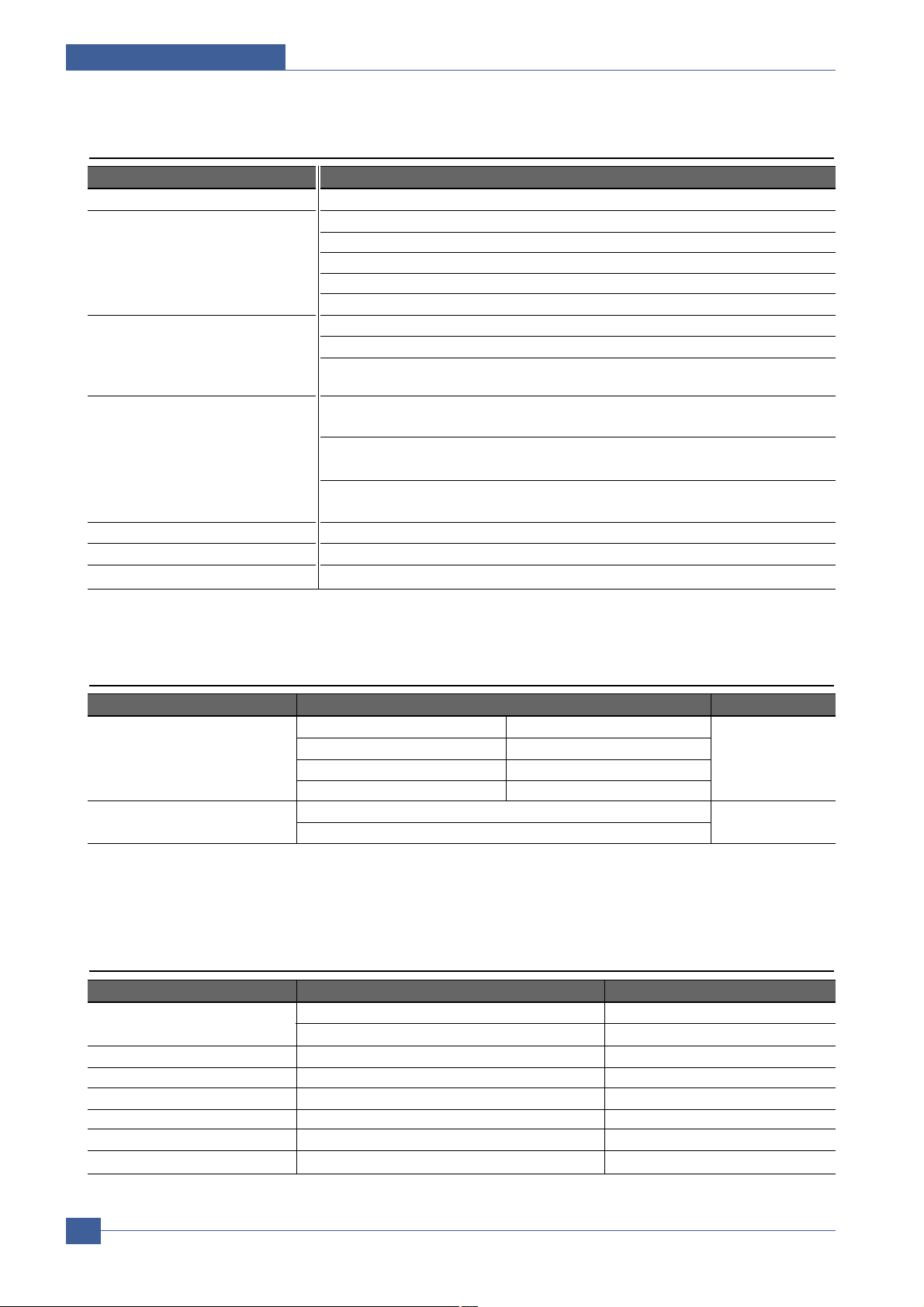
3.1 General Specifications
ITEM DESCRIPTION
Print Method Non-impact Electro-photography
Development system Non-Magnetic, Mono-Component, Non-Contact Developing System
Transfer system Conductive roller transfer
Fuser Unit(T oner fix) Pressure and Heating with e-coil
*Print Speed Up to 33 PPM in A4 size
Up to 35 PPM in Letter size
Resolution Up to 1200 x 1200 DPI effective output
Source of Light Laser diode (LSU : Laser Scanner Unit)
Warm-Up Time Power-on boot : 40 seconds
First Print Time 9 seconds or less
Feed Method Cassette & Manual, Option Feeder(SCF)
duplex Optional
Media Size 76mm * 128mm(3 *5”) to 216mm * 356mm(8.5 *14”)
Media Thickness 16 ~ 28 lb(60 to 105g/m2), Manual : 16 ~43lb(60 to 163g/m2)
Dimension(W X D X H) 396 X 453 X 348 mm / 15.6” X 17.8” X 13.7” inch (without options)
Weight Net : 17.5 Kg with print cartrige
Gross : 21 Kg
**Acoustic Noise Stand by : Less than 35 dB
Printing: Less than 55 dB
Sleep mode : Background Noise
Power save mode Enable
Toner save mode Enable
Consumable Parts Retard Roller Up to 150,000 Pages
Transfer Roller Up to 150,000 Pages
Fuser Assembly Up to 150,000 Pages
Toner Sensor Y es(dot counting)
Toner Type Non-Magnetic toner
Toner Initial 6,000 pages@ISO 5% coverage
Toner sale 6,000 or 12,000 pages@ISO 5% coverage
Optional Parts Optional Tray Paper Capacity : 500 Sheets
Wired NPC Ethernet 10/100 base TX
(ML-3560/ML-3561N Protocols : TCP/IP, SPX/IPX, Ethertalk, SNMP,
: Optional HTTP1.1, DLC/LLC
ML-3560 : Basic) 8MB RAM Buffer for faster graphics performance
2MB Flash Memory for upgrade
Throughput : 200 ~ 300K TCP/IP
SDRAM DIMM 32, 64, 128, 256MB 100PIN SDRAM DIMM
Wireless NPC IEEE802.11b supportT
(Option) Speed : 1 1, 5.5, 2, 1 Mbps
Operation range : 30m(Indoors), 150m(Outdoors)
Duplex Unit
* Print speed will be affected by Operating System used, computing performance, application software, con-
necting method, media type, media size and job complexity.
** Sound Pressure Level, ISO 7779
Page 14
Service Manual
Specifications
3-2
Samsung Electronics
3.3 Electrical Specification
ITEM DESCRIPTION REMARK
Input Voltage Nominal input voltage 220-240 VAC / 110~127VAC
Input voltage range 198-254 VAC/ 99~135VAC
Nominal frequency 50/60 MHz
Frequency tolerance +3Hz
Power Consumption
Printing : 600W(average)
Sleep : under 12W
3.2 Controller Specification
ITEM DESCRIPTION
Processor(CPU) SPGPv3 400Mhz
Memory NAND FLASH 32MB
RAM : 32MB
Option DIMM module : 32, 64, 128, 256MB (SDRAM)
100Pin SDRAM DIMM (
Use only Samsung Memory Parts made specifically for this printer.
)
EEPROM(NVRAM) : 4Kbyte
Emulation PCL6 : Win9x/ME/NT4.0/2000/XP
Postscript Level3 : MAC OS 8.6 ~ 9.2/10.1 ~ 10.3
PCL5e : Various Linux OS including Red Hat, Caldera, Debian, Mandrake, Slackware,
SuSE and Turbo Linux
Interface Parallel : IEEE 1284 Bidirectional Parallel
- Modes supported : Compatible,Nibble,Byte,ECP
USB(without HUB mode)
-USB 2.0 compliant -High Speed
Network Interface : - 10/100 Base TX
- 802.1 1b Wireless LAN
Interface switching Automatic
Interface time-out 999 seconds
Font 45 Scalable Font , 1 Bitmap Font ,Postscript 3 internal font 136
3.4 TONER Cartridge (Developer)
ITEM DESCRIPTION REMARK
Life span Starter: Up to 6,000 pages
A4 Size, @ISO 5% Coverage, SIMPLEX
Replacement : Up to 12,000 pages
Developing Non Contact Developing
Charging Conductive Roller Charging
Toner supply Method Not possible, replace the whole print cartridge.
Toner checking sensor Fitted
Ozone 0.1PPM or less
Style Single cartridge
Page 15
3.6 Paper Handling Specifications
>> Input Paper Size
Supported Paper, Transparencies, and Other Specialty Media
PAPER TYPE/SIZE DIMENSIONS TRAY 1(MPT) TRAY 2 TRA Y3 2-SIDED PRINTING
Letter 8.5 x 11 in. O O O O
Legal 8.5 x 14 in. O O O O
US Folio 8.5 x 13 in. O O O O
A4 210 x 297 mm O O O O
B5-JIS 182 x 257 mm O O O
ISO-B5 176 x 250 mm O O O
A5 148 x 210 mm O O O
Executive 7.25 x 10.5 in. O O O
Statement 5.5 x 8.5 in O
US Postcard 3.5 x 5.5 in O
Index Card 3 x 5 in O
A6 Postcard 105 x 148 mm O
Envelopes
Monarch 3.88 x 7.5 in. O
#10 Commercial 4.13 x 9.5 in. O
C5 162 x 229 mm O
C6 1 14 x 162 mm O
DL 1 10 x 220 mm O
Transparencies
Letter 8.5 x 11 in. O X X X
A4 210 x 297 mm O X X X
Labels
Letter 8.5 x 11 in. O
A4 210 x 297 mm O
Custom Width = 76~216 mm (3~8.5 in.); O
Length = 127~356 mm (5~14 in.)
Tray 1 (MPT) Weight : 60~163 g/m 2 (16~43 lb.)
Tray 2 and 3 Weight : 60~105 g/m 2 (16~28 lb.)
Duplex Weight : 75~90 g/m 2 (20~24 lb.)
O : Supported
3.5 Environmental Condition
ITEM OPERA TING STORAGE
Temperature 10~30˚C(50-90˚F) -20~40˚C (-4~104˚F)
Humidity 20~80%RH 10~80%RH
Specifications
Service Manual
3-3
Samsung Electronics
Page 16

Service Manual
Specifications
3-4
Samsung Electronics
>> Input capacity
>> Output capacity
ITEM DESCRIPTION
Cassette Paper 500 sheets (75gr)
MP tray Paper 100 sheets (75gr)
Transparencies 50 sheets
Envelopes 10 sheets
Labels 25 sheets
Option Cassette 500sheets (75gr)
ITEM DESCRIPTION
Face Down(Top) tray 250 sheets
Face UP(Rear) tray 100 sheets
Page 17
Summary of Product
Service Manual
4-1
Samsung Electronics
4
4
4. Summary of Product
This chapter describes the functions and operating principal of the main component.
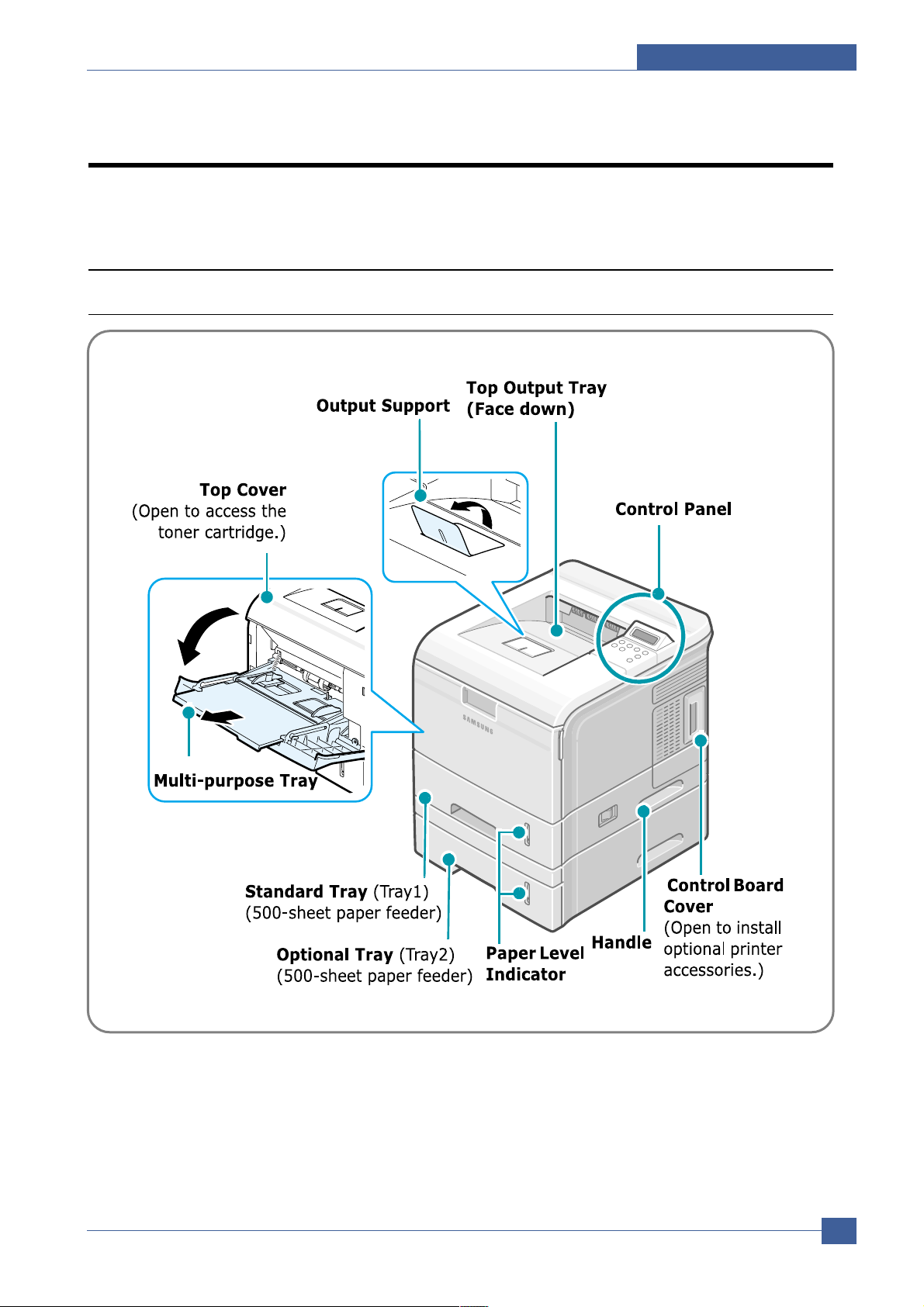
4.1 Printer Components
4.1.1 Front View
Page 18
Service Manual
Summary of Product
4-2
Samsung Electronics
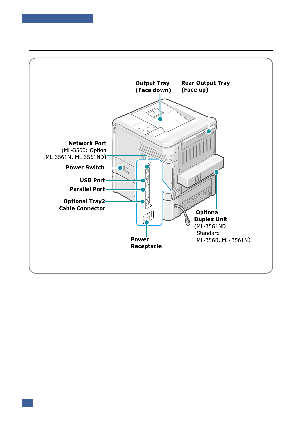
4.1.2 Rear View
Page 19
Summary of Product
Service Manual
4-3
Samsung Electronics
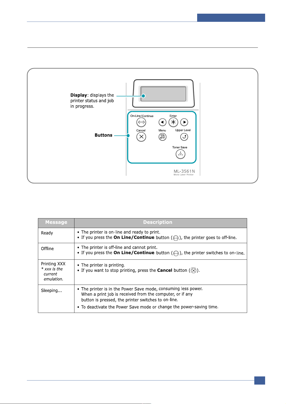
4.1.3 Control Panel
The control panel on the top right side of your printer has the display and the nine buttons.
4.1.3.1 Display
Page 20
Service Manual
Summary of Product
4-4
Samsung Electronics
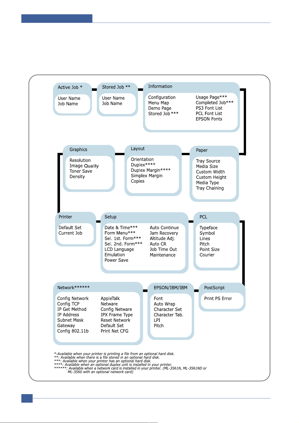
4.1.3.2 Overview of Control Panel Menus
The control panel menus are used to configure the printer for your environment.
Page 21
Summary of Product
Service Manual
4-5
Samsung Electronics
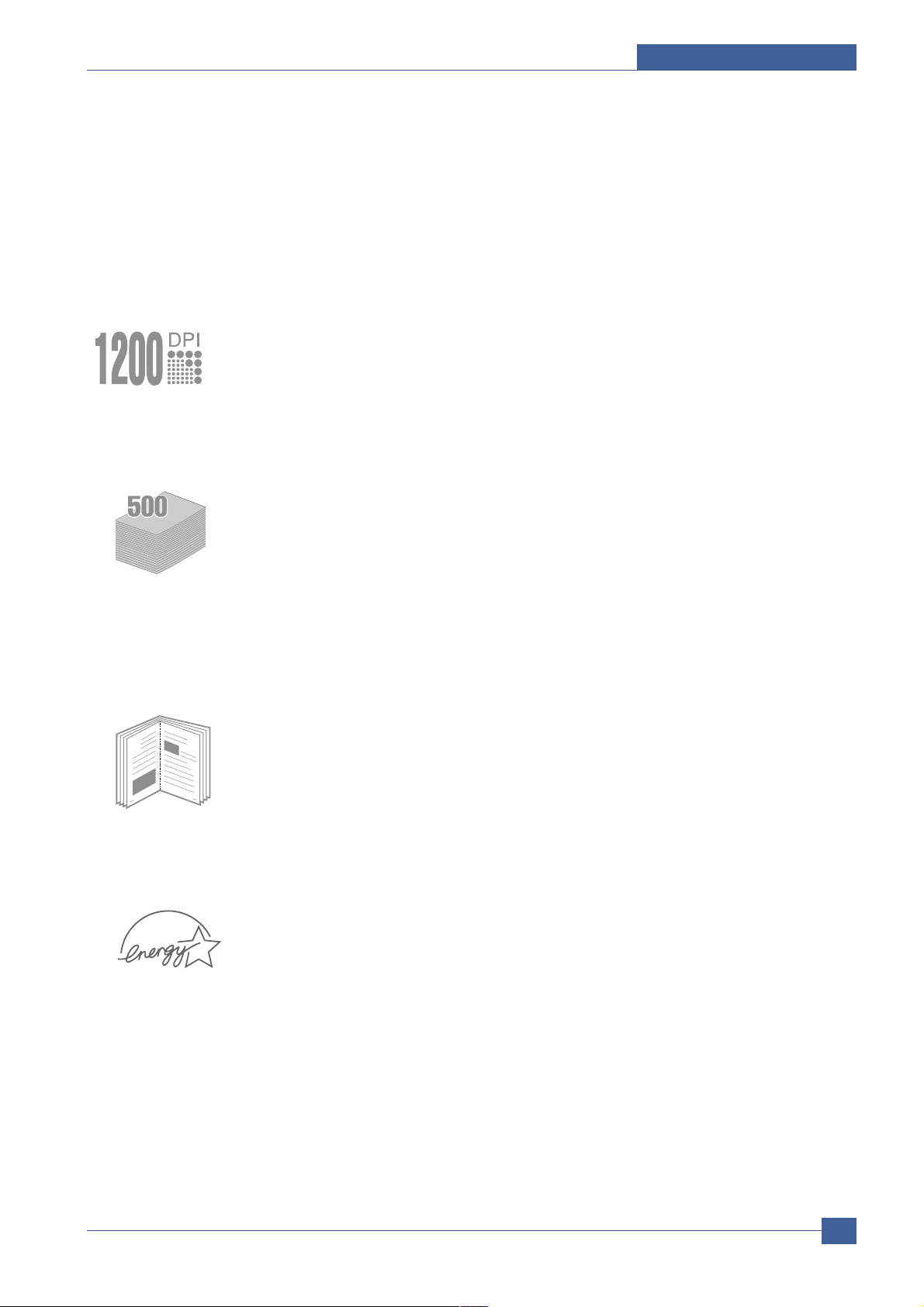
4.1.3.3 Special Features
Y our new printer is equipped with special features that improve the print quality,giving you a competitive edge.
Y ou can:
Print with excellent quality and high speed
• Y ou can print at 1200 dots per inch (dpi).
• Y our printer prints 35 pages-per-minute (Letter size), 33 pages-per-minute (A4 size).
Handle paper flexibly
• A100-sheet Multi-Purpose T ray supports letterheads, envelopes,labels,transparencies,custom-sized materials,postcards,and heavy paper.
• Standard 500-sheet input tray (T ray1)and optional 500-sheet input tray (Tray2)supports all
standard sizes of paper.
• Two output tray;select either the top output (face-down)or the rear output tray (face-up)for
the most convenient access.
• Straight-through paper path capability from the Multi-Purpose T ray to the rear output tray.
Create professional documents
• Y ou can customize your documents using W atermarks, such as “Confidential.”
• Print Booklets .This feature enables you to easily print the pages required to create
books.Once printed,all you have to do is to fold and staple the pages.
• Print Posters .The text and pictures of each page of your document are magnified and printed across the selected sheet of paper.After the document has printed,trim off the white
edges of each sheet.Tape the sheets together to form a poster.
Save your time and money
• This printer allows you to use Draft to save toner .
• Y ou can print on both sides of the paper to save paper (double-sided printing ).
• Y ou can print multiple pages on one single sheet of paper to save paper (N-Up printing ).
• Preprinted forms and letterheads can be printed on plain paper.
• This printer automatically conserves electricity by substantially reducing power consumption
when not printing.
• This printer meets Energy Star guidelines for energy efficiency.
(
)
Page 22
Service Manual
Summary of Product
4-6
Samsung Electronics
Expand the printer capacity
The following printer options and supplies are available for Phaser 3500 printers:
Print in various environments
• You can print in Windows 95/98/Me/NT4.0/2000/XP .
• Your printer is compatible with Linux and Macintosh .
• Your printer comes with both the Parallel and USB interfaces.
You can also use a network interface. ML-3561N comes with a built-in network interface,10/100 Base TX. ML-3561N also has a wireless network interface. But, you need to add
the optional network interface card to ML-3560.
Printer Features
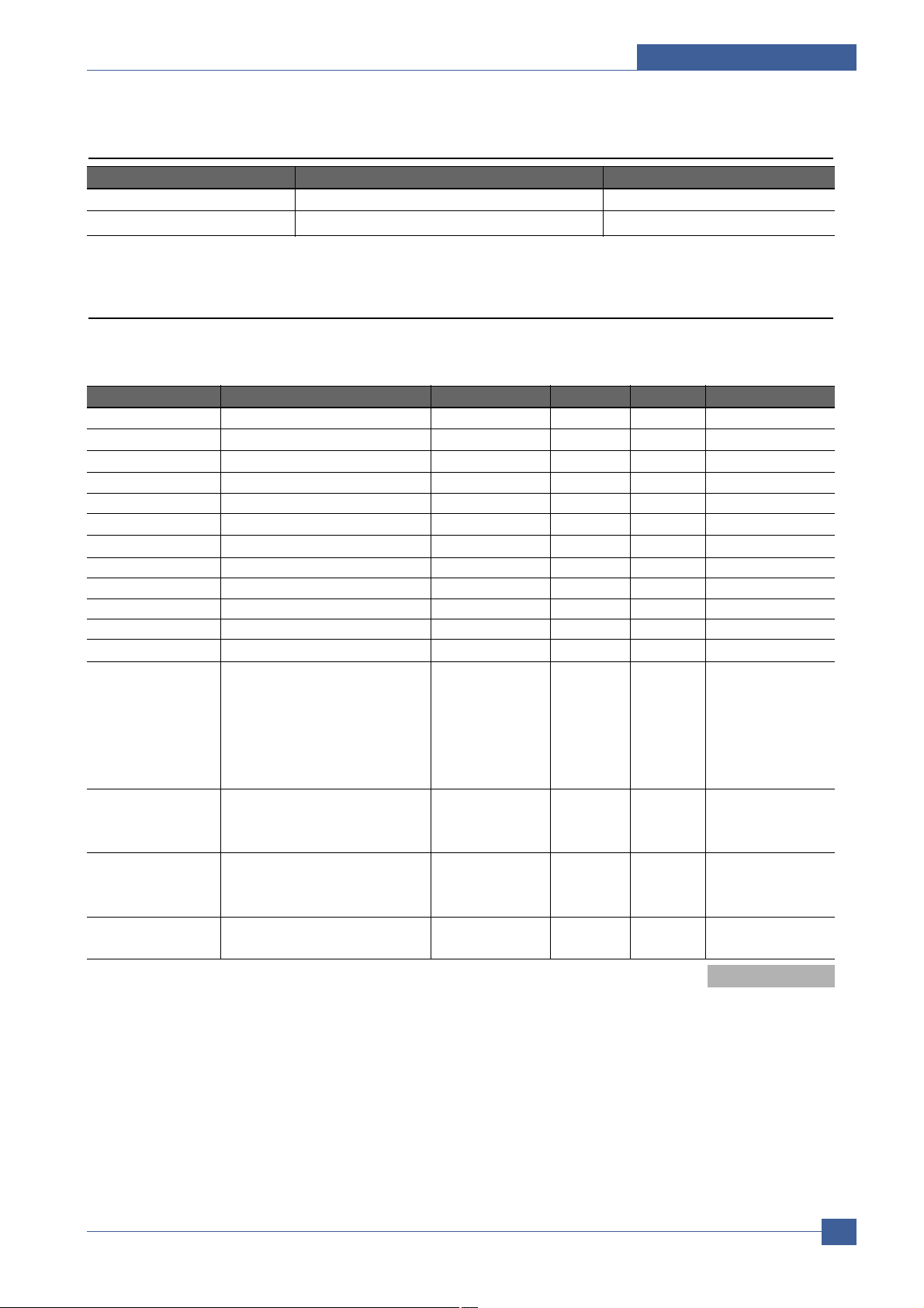
The table below lists a general overview of features supported by your printer.
Features Printer Configuration
Ml-3560 ML-3561N ML-3561ND
Maximum Print Speed Monochrome 35 35 35
Memory ( Standard) 32 Mbytes 32 Mbytes 64 Mbytes
Up to 286 Mbytes Optional
PostScript and PCL Fonts Yes Yes Yes
Default Resolutions ( dpi) 600 x 600 dpi 600 x 600 dpi 600 x 600 dpi
500-Sheet Feeder Optional Optional Optional
Network Interface Optional Standard Standard
Automatic 2-Sided Printing ( Duplex) Optional Optional Standard
HDD Optional Optional Optional
Wire Less N/W( 802.11b) Optional Optional Optional
Duplex Unit Optional Optional Standard
Item Part Number
32 Mbytes additional RAM memory ML-05MB/SEE
64 Mbytes additional RAM memory ML-05MC/SEE
128 Mbytes additional RAM memory ML-05MD/SEE
256 Mbytes additional RAM memory ML-05ME/SEE
Network Interface Card ( NIC) Duplex Unit 500-Sheet Feeder ( includes tray) Standard-Capacity Print Cartridge ( 6,000 pages @ 5% area coverage) ML-3560D6
High-Capacity Print Cartridge ( 12,000 pages @ 5% area coverage) ML-3560DB
Page 23
Summary of Product
Service Manual
4-7
Samsung Electronics
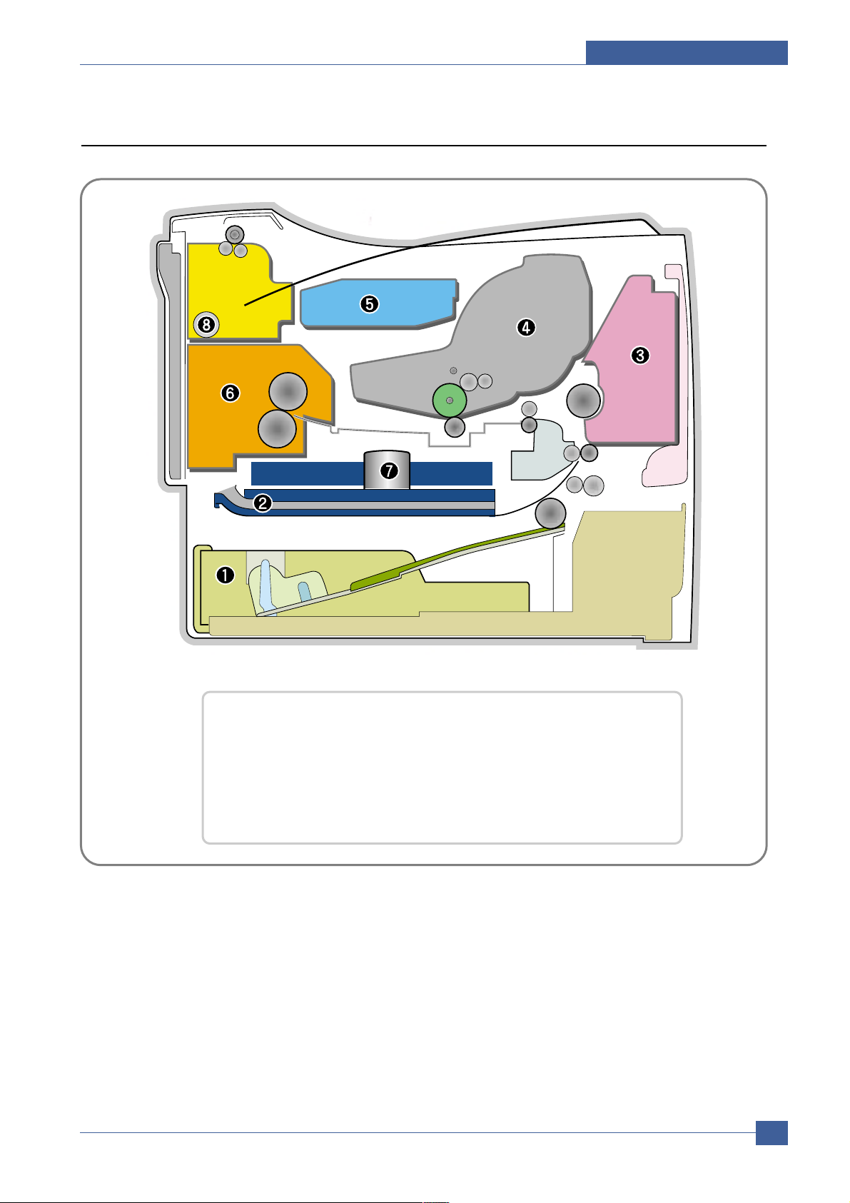
4.2 System Layout
❶ Cassette ❷ Duplex
❸ MPF ❹ Print Cartridge
❺ LSU ❻ Fuser
❼ SMPS & HV PS Board ❽ Duplex Solenoid
Page 24

Service Manual
Summary of Product
4-8
Samsung Electronics
4.2.1 Feeding
It is consists of a basic cassette, an MP tray for supplying different types of media : envelope, label special paper, duplex unit, and parts related to paper transferring.
1) Separation method
Separate it from the friction pad mounted to the center of the cassette and apply retard roller that
uses a spring clutch. Afeed roller uses an electronic clutch to control driving power.
2) Basic cassette
It takes a center loading method and applies 'friction pad separating method.' It means that there is
a paper sensor, but a paper size is detected after detecting the first paper by software.
Both the side guide and the rear guide can be adjusted for for various types of papers from A5 to
legal size paper.
It has a paper existence sensing function ( Capacity: 500 sheets of general paper) , paper arranging
function, various size papers accepting function, SCF paper path function, and displaying function
of paper remaining amount.
In the front side, there is a paper level indicator.
3) Pick-up roller
It has functions such as a paper pickup function, driving control function, paper feeding function,
and removing electronic static function.
4) Retard roller
It takes an arrangement method which uses a stopper roller and a weight without electric actuator.
It has paper separating function, driving control function, and multi feeding prevention function.
6) Registration roller
It has a paper arranging function, paper transferring function, paper detecting function, jam removing function, and so on.
7) MP tray
It has a paper arranging function, paper transferring function, jam removing function, and so on.
It uses rubbing pad method to feed 100 sheets of general papers and 10 envelops.
It is possible to extend to 300mm for accepting a legal size paper.
8) Duplex unit
It has paper transferring function, paper guide function, jam removing function, paper sensing function, and main board supporting function.
It is designed for basic attachment, and the duplex feeding takes a side feeding method. Usable
papers are A4, letter, and legal size paper.
For removing a jam occurred in a front part, it is designed to open a cassette and a guide.
It is designed to open a rear cover to remove a jam in a rear part.
If a face up tray is open, the duplex option cannot be used.
9) SCF (Second Cassette Feeder)
It is the same method with the main cassette, and the capacity is 500 sheets.
It has a separate driving mechanism. It is designed for a common use with a main cassette.
Page 25

Summary of Product
Service Manual
4-9
Samsung Electronics
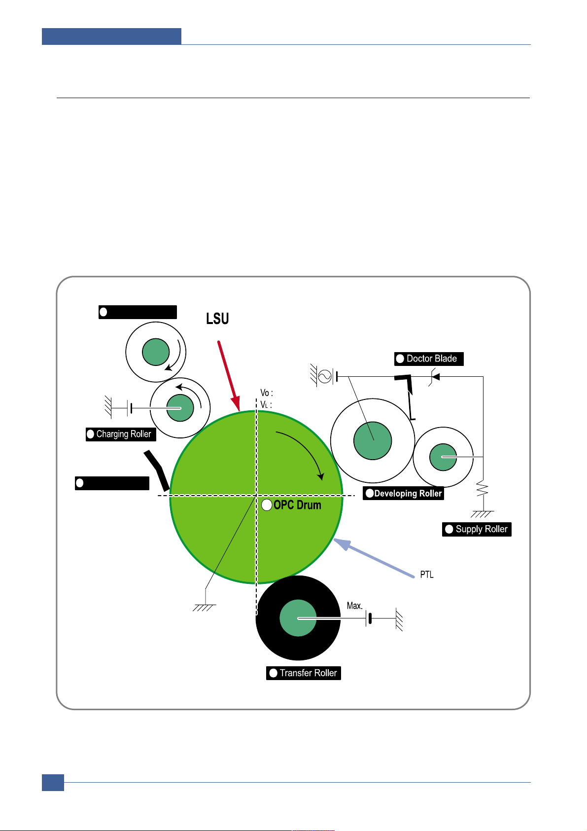
4.2.2 Transfer
It consists of a PTL ( Pre-transfer Lamp) and a transfer roller. A PTL sheds light on an OPC drum, lowers
an electric potential of an OPC drum's surface, and improves the efficiency of the transfer.
A transfer roller transfers toner on an OPC drum to the paper.
Life span: Print over 150,000 sheets ( In 16~27 )
4.2.3 Driver Ass'y
By driving the motor, the system takes power. It consists of a main motor for feeding fuser and duplex
reverse turn, and a deve-motor for a toner cartridge.
- Main Motor : DC 24V , Rated RPM : 1380 rpm
- Deve Motor : DC 24V , Rated RPM : 1407 rpm
4.2.4 Fuser
It is consisted of a heat lamp, heat roller, pressure roller, thermistor and thermostat. It sticks the toner on
a paper by heat and pressure to complete the printing job.
- E-coil Heator : 1,300 Watt
50W
1) Thermostat
When a heat lamp is overheated, a Thermostat cuts off the main power to prevent over-heating.
- Non-Cotact type Thermostat
3) Heat roller
The heat roller transfers the heat from the e-coil to apply a heat on the paper. The surface of a
heat roller is coated with Teflon, so toner does not stick to the surface.
4) Pressure roller
A pressure roller mounted under a heat roller is made of a silicon resin, and the surface also is
coated with Teflon. When a paper passes between a heat roller and a pressure roller, toner
adheres to the surface of a paper permanently.
5) Items for safety
Protecting device for overheating
- 1st protection device: Hardware cuts off when overheated
- 2nd protection device: Software cuts off when overheated
- 3rd protection device: Thermostat cuts off main power.
Safety device
- A fuser power is cut off when a front cover is opened
- Maintain a temperature of fuser cover's surface under 80( C for user, and attach a caution
label at where customer can see easily when customer open a rear cover.
4.2.5 LSU (Laser Scanner Unit)
It is the core part of the LBP which switches from the video data received to the controller to the electrostatic latent image on the OPC drum by controlling laser beam, exposing OPC drum, and turning principle
of polygon mirror. The OPC drum is turned with the paper feeding speed. The /HSYNC signal is created
when the laser beam from LSU reaches the end of the polygon mirror, and the signal is sent to the controller. The controller detects the /HSYNC signal to adjust the vertical line of the image on paper. In other
words, after the /HSYNC signal is detected, the image data is sent to the LSU to adjust the left margin on
Page 26
Service Manual
Summary of Product
4-10
Samsung Electronics
4.2.6 Print Cartridge
By using the electronic photo process, it creates a visual image. In the print cartridge, the OPC unit and
the toner cartridge unit are in a body. The OPC unit has OPC drum and charging roller, and the toner
cartridge unit has toner, supply roller, developing roller, and blade ( Doctor blade)
- Developing Method: Non-contacting method
- Toner : Non magnetic 1 component pulverized type toner
- The life span of toner : 6,000 or 12,000 pages ( LSA Pattern/A4 standard)
- Toner remaining amount detecting sensor : Yes
- OPC Cleaning : Cleaning blade type
- Management of disusable toner : Collect the toner by using Cleaning Blade
- OPC Drum protecting Shutter : Yes
- Classifying device for toner cartridge : ID is classified by interruption of the frame channel.
Cleaning Roller
Cleaning Blade
-650V
0.15mW
200V
-1.25KV
V
DC
= -460V
V
PP
= 1520V, f = 2.5KHz, Duty(-) = 32%
1
2
3
4
5
6
7
8
+5.0kV
-50V
+
-
<Toner Cartridge Layout>
Page 27
Summary of Product
Service Manual
4-11
Samsung Electronics
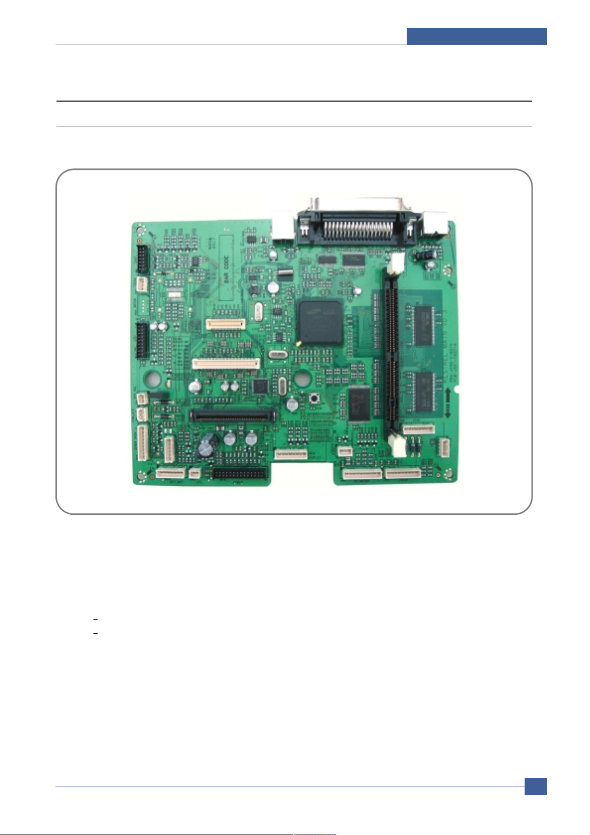
4.3 Engine H/W Specifications
4.3.1 ML-3560 (PCL) Main Board
The Engine Board and the Controller Board are in one united board.
4.3.1.1 Asic(SPGP V3)
• RM1020E (I-Cache : 32KB, D-Cache-32KB)
• 32-bit RISC embedded processor core
• Dual bus architecture for bus traffic distribution
AMBA High performance Bus ( AHB)
System Bus with SDRAM
• SDRAMC
- 32 Bits Only, 100MHz
- 5 Banks ( Up to 128MB per Bank)
Page 28

Service Manual
Summary of Product
4-12
Samsung Electronics
• ROMC - 4 Banks ( Up to 16MB per Bank)
• IOC - 6 Banks ( Up to 16MB per Bank)
• DMAC - 4 Channels
• IEEE1284 compliant parallel port interface
• Printer Video Controller for LBP engines
• Graphic Execution Unit for Banding support of Printer Languages
• HCT / JBIG (Encoding / Decoding)
• Fully Hardware Rotator, Scaler and Halftoner support
• Printer Video Controller for LBP engines
- PV C : Printer V ideo Controller without RETAlgorithm
- HPV C : Printer V ideo Controller with RET algorithm( Line Memory & Lookup Table Memory : 512 x 8,4096 x 16)
Dual / Single Beam, LV DS Pad ( V DO, HSYNC)
• PCI Controller
- 32Bits, 33/66MHz
- PCI Local Bus Specification rev. 2.2 compliant
- Host /Agent Mode ( Support 4 Devices in Host Mode)
• NAND Flash Controller
- 8/16 Bits, H/W ECC Generation
- Auto Boot Mode ( using internal SRAM, 4KB)
• Engine Controller
- LSU Interface unit
- Step Motor : 2 Channels
- PWM : 8 Channels
- ADC : 6 Channels
• USB 2.0 Interface
• Package : 496pins PBGA
• Power : 1.2V ( Core) , 3.3V ( IO) power operation
• Speed : 400MHz core( ARM10) operation, 100MHz bus operation
Page 29

Summary of Product
Service Manual
4-13
Samsung Electronics
4.3.1.2 Memory
• Nand Flash Memory : It stores System Program and downloads the System Program through PC Interface, and in case
of model for export it compresses the PCLfont, then stores it.
- Capacity : 32M byte
• SDRAM : It is used as Swath Buf fer,System Working Memory Area,etc.when printing. It stores Font List,compressed into
Flash memory,on DRAM and uses it as PCL font in case of model for export.
- Capacity : 32M Byte( Basic) ,up to 256Mbyte ( User Option)
- Type : SDRAM 100MHz/133MHz ,16bit
4.3.1.3 Others
The Option PBA can be mounted for supporting the serial communication.
Page 30
Service Manual
Summary of Product
4-14
Samsung Electronics
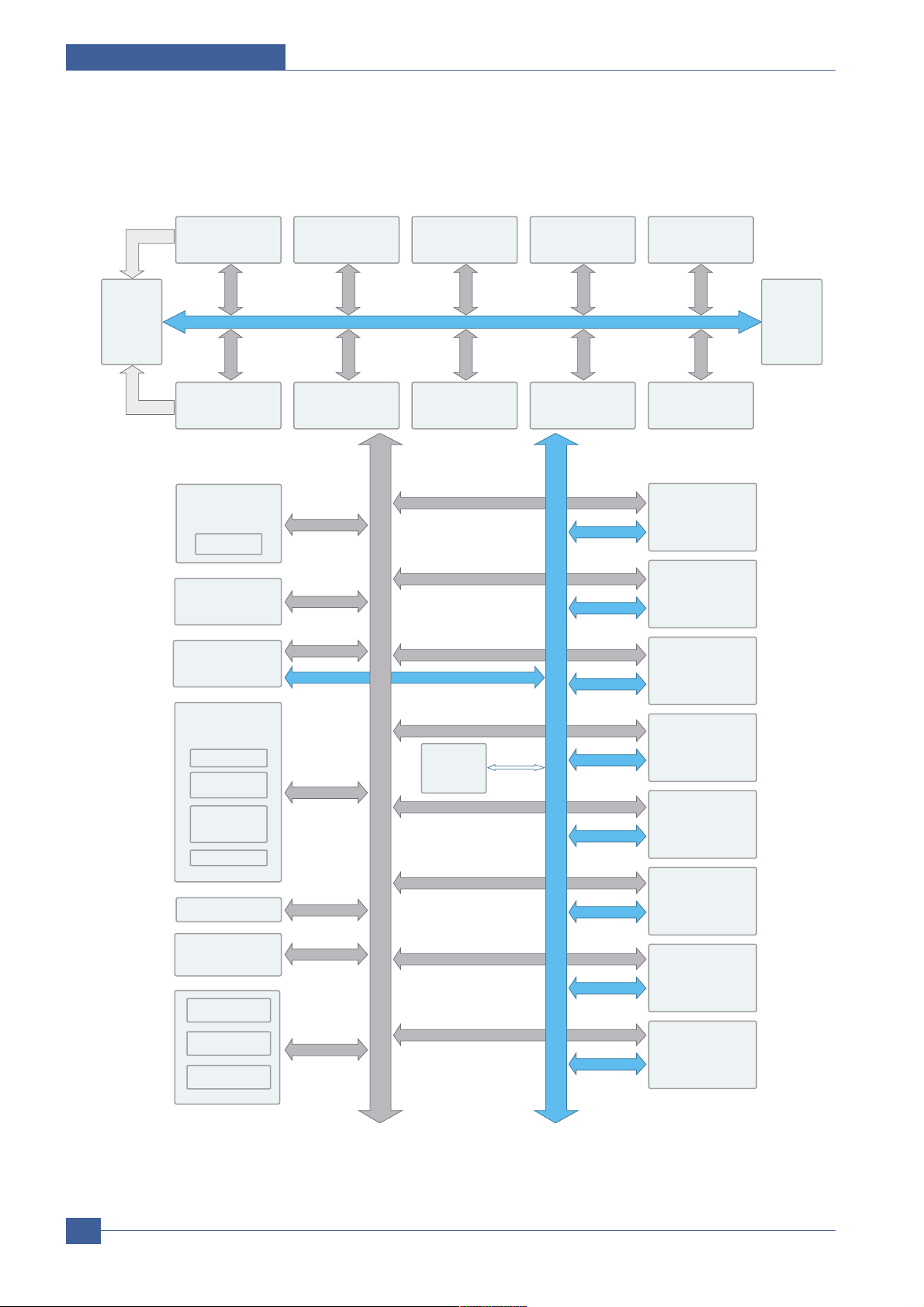
4.3.1.4. SPGP V3 Internal Block Diagram
CLOCK & RESET
GENERATOR
3PLL
Dual/Single Beam
HPVC
7200x16
1024x8
Dual Beam
PVC
Parallel Port
Interface
SDRAM
CONTROLLER
(5CH)
HCT
JBIG
256x3.2x7
1024x8x2
GRAPHIC
EXECUTION
UNIT
ROTATOR/
SCALER/
HALFTONER
1024X8, 256X8
ENGINE
CONTROLLER
LSU I/F
PULSE WIDTH
MODULATOR
MOTOR
CONTROLLER
2X2X128X16
ADC/DAC
MISC & BIST
CONTROLLER
ENGINE
COMM. I/F
INTERRUPT
CTRL
TIME CONTROL
UNIT(6CH)
SYSTEM
BUS
ARBITER
ROM
CONTROLLER
PCI BRIDGE
PCI 2.2
NAND Flash
CONTROLLER
ARM1020E
EXTERNAL
DMA CONTROLLER
(4CH)
IO
CONTROLLER
SFR BUS
INTERFACE
DECODER
SYSTEM BUS
INTERFACE
ETHERNET
UART(5CH)
12C CONTROLLER
AHB
AMBA
BUS
TEST &
JTAG
ADDR/
DATA
MLIX
RTC
Page 31

Summary of Product
Service Manual
4-15
Samsung Electronics
4.3.1.5 Sensor Input Circuit
• Paper empty sensing
1. Cassette paper empty( Tray1)
- ‘Empty Sensor’detects whether the paper is in the Tray1.
2. MP paper empty( MP Tray)
- ‘MP empty sensor’detects whether the paper is in the MP Tray.
• When ‘Auto’ mode is Setting
If the ‘MP Tray’and ‘Tray’are all empty, ‘Paper empty Tray1’ messeage is displayed on the LCD panel.
• Feed sensing
The feed sensor detects that the entering paper from Tray1 or Tray2.
When ‘Jam at top, open top cover’message is displayed on the LCD panel, the feed sensor should be
checked.
• Paper exit sensing
The exit sensor detects that ‘Jam at exit’ error.
When the paper sticks into the exit part, ‘Jam at Exit Open top cover’message is displayed on the LCD panel.
• Cover open sensing
The cover open switch is on the top frame, it dectects whether top cover is open or closed. When top cover is
open, ‘Close Open’ message is diplayed on the LCD panel.
• Motor driving
There are two BLDC motors. The one is for developer driving and the other is for other driving part operating.
• Output tray sensor
The output tray sensor detects that the exit paper out for output tray.
Page 32

Service Manual
Summary of Product
4-16
Samsung Electronics
4.3.2 SMPS & HVPS board
The SMPS supplies DC Power to the System. It takes 110V /220V and outputs the +3.3V , +5V +24V to supply the power
to the main board. The HV PS board creates the high voltage.
Page 33

Summary of Product
Service Manual
4-17
Samsung Electronics
4.3.2.1 HVPS (High Voltage Power Supply)
• Transfer High Voltage (THV+)
- Input V oltage : 24 V DC 15%
- Output V oltage : MAX +5.0KV 5 %, ( Duty V ariable)
- Input contrast of the V oltage stability degree : under 5 %( fluctuating input 21.6V ~26.4V )
Loading contrast : 5 %or less
- Output V oltage Rising Time : 100 ms Max
- Output V oltage Falling Time : 100 ms Max
- Fluctuating transfer voltage with environmental various : +600 V ~5 KV
- Environment Recognition Control Method : The THV -PWM ACTIV E is transfer active signal. It detects the
resistance by recognizing the voltage value, F/B, while permits the environmental recognition voltage.
- Output V oltage Control Method : T ransfer Output V oltage is outputted and controlled by changing Duty of
THV PWM Signal.
• Charge Voltage (MHV)
- Input V oltage : 24 V DC 15%
- Output V oltage : -1.1KV ~ -1.6KV DC 3%
- Output V oltage Rising Time : 50 ms Max
- Output V oltage Falling Time : 50 ms Max
- Output Loading range : 30 ~1000
- Output Control Signal( MHV -PWM) : CPU is HV output when PWM is Low
• Cleaning Voltage (THV-)
- The ( +) Transfer V oltage is not outputted because the THV PWM is controlled with high.
- The ( -) Transfer V oltage is outputted because the THV -Enable Signal is controlled with low
- The output fluctuation range is big because there is no Feedback control.
- Output V oltage : -1.0KV 15%( when cleaning, 200M
• Developing Voltage (DEV)
<DC>
- Input V oltage : 24 V DC 15%
- Input contrast of the output stability degree : 3 % or less Loading contrast : 3 % or less
- Output V oltage Rising Time : 50 ms Max
- Output V oltage Falling Time : 50 ms Max
- Output Loading range : 10M ~1000
- Output Control Signal ( DEV Vdc-PWM) : the CPU output is HV output when PWM is low.
<AC>
- Input V oltage : 18Vdc
- Output V oltage : PWM Control ( Vp-p, VAC)
- Input Contrast : 3 %
- Output Control Signal : The CPU is HV Output when Dev VAC Vp-p, DEV AC ph/M, VAC On-Off is low.
• Supply
- Output V oltage : ZENER using, DEV
- Input contrast of the output stability degree : under 3 % Loading contrast : 3% or less
- Output V oltage Rising Time : 50 ms Max
- Output V oltage Falling Time : 50 ms Max
- Output Loading range : 10 ~1000
- Output Control Signal ( DEV Vdc-PWM) : the CPU is HV output when PWM is low.
Page 34

Service Manual
Summary of Product
4-18
Samsung Electronics
4.3.2.2 SMPS (Switching Mode Power Supply)
t is the power source of entire system. SMPS has three output channels. Which are 3.3V , +5V and +24V .
• AC Input
- Input Rated V oltage : 220 ~ 240V AC / 110 ~ 127V AC
- Input V oltage fluctuating range : 198 ~ 254V AC / 99 ~ 135V AC
- Rated Frequency : 50/60 Hz
- Frequency Fluctuating range : 47 ~63 Hz
• Rated Output Power
• Power Consumption
• Length of Power Cord :1830 50mm
• Power Switch :Use
NO ITEM CH1 CH2 CH3 CH4
1 CHANNEL NAME +3.3V +5V +24.0V S 24.0V F
2 CONNECTOR PIN CON 3 CON 3 CON 3
3.3V PIN:9,11,13 5V PIN:15,17 24V PIN:1,3,5
GND PIN:21 GND PIN:19 GND PIN:23,25,27
3 Rated Output 3.3V 5% +5V 5% +24V 10%+15% +24V 10%+15%
( 3.13~3.47V ) ( 4.75~5.25V ) ( 21.6~27.6V ) ( 21.6~27.6V )
4 Max.Output Current 2.0A 1.0 A 3.8A 0.7A
5 Peak Loading Current 2.5 A 1.5 A 4.0 A 1.0A
6 RIPPLE NOISE V oltage Under 100mV p-p Under 150mV p-p Under 500mV p-p Under 500mV p-p
7 Maximum output 6.6W 4.0W 67.2W 16.8W
8 Peak output 6.6W 5.0W 91.2W 16.8W
9 Protection for loading Fuse Protection Rugulator Fuse Protection, Short protection
shortage and or Shut down short protection Shut down
overflowing current ( 2.5~5.0A) ( 5.5~7.5A) ,
Drop( Trp -10%)
NO Item System
1 Stand-By A V G : 80 Wh
2 PRINTING A V G : 600 Wh
3 Sleep-Mode A V G : 12 Wh under ( Basic model)
Page 35

Summary of Product
Service Manual
4-19
Samsung Electronics
• Feature
- Insulating Resistance :50 or more ( at DC 500V )
- Insulating revisiting pressure : Must be no problem within 1 min.( at 1500V ac, 10mA)
- Leaking Current : under 3.5mA
- Running Current : under 40A PEAK ( AT 25 , COLD ST AR T) under 60APEAK ( In other conditions)
- Rising Time : within 2Sec
- Falling Time : over 20ms
- Surge : Bi-wave 6kV 12ohm ( Com)
Bi-wave 3kV 2ohm ( Nor)
• Environment Condition
- Operating temperature range :0 40
- Maintaining temperature range :-25 85
- Preserving Humidity Condition :30% ~ 90%RH
- Operating atmospheric pressure range : 1atm
4.3.2.3 Fuser control
• When the power voltage of the machine is too high or too low Fuser on is stopped to protect the fuser .
• When the AC is not applied to the fuser control circuit, the fuser does not work then ‘Fuser low heat error’ would be
occured.
• When the temperature of the fuser is too high, ‘Engine over heat’error occurs if the cooling operation is not sufficient.
Page 36

Service Manual
Summary of Product
4-20
Samsung Electronics
4.3.3 Engine F/W
4.3.3.1.Control Algorithm
• Feeding
If feeding from a cassette, the drive of the pickup roller is controlled by controlling the solenoid. The on/off of the
solenoid is controlled by controlling the general output port or the external output port. If feeding from a manual
feeder, decide to insert the paper according to the operation of the manual sensor, and by driving the main motor,
insert the paper in front of the feed sensor. While paper moves, occurrence of Jam is judged as below.
• Driver
By gearing,the main motor drives the rollers such as feeding roller, driven by deve-Motor, fuser roller, and exiting
roller. The step motor is controlled for the such acceleration section and steady section. In the initial stage of the
motor run, appoint the acceleration section to prevent the step-out of the motor . It is controlled by the A3977 motor
driver IC. The step signal and the enable signal are sent to make the phase for driving the motor in CPU.
• Transfer
The charging voltage,developing voltage and the transfer voltage are controlled by PWM ( Pulse Width
Modulation) . The each output voltage is changeable due to the PWM duty. The transfer voltage admitted when
the paper passes the transfer roller is decided by environment recognition. The resistance value of the transfer
roller is changed due to the surrounding environment or the environment of the set, and the voltage value, which
changes due to the environments, is changed through AD converter . The voltage value for impressing to the transfer roller is decided by the changed value.
ITEM Description
JAM 0
JAM 1
JAM 2
DUPLEX
JAM 1
DUPLEX
JAM2
- After pick up, paper cannot be entered due to paper is not fed.
-
After pick up, paper entered but it cannot reach to the feed sensor in certain time due to slip, etc.
- After pick up, if the feed sensor is not on, re-pick up. After re-picking up, if the feed sensor is not
on after certain time, it is JAM 0.
* It is a status that the leading edge of the paper doesn’t pass the feed sensor.
- Even though the paper reaches to the feed sensor, the feed sensor doesn’t be ON.
* It is a status that the leading edge of the paper already passes the feed sensor
- After the leading edge of the paper passes the feed sensor,the trailing edge of the paper cannot
pass the feed sensor after a certain time.( The feed sensor cannot be OFF)
- After the leading edge of the paper passes the feed sensor, the paper cannot reach the exit sen sor after certain time.( The exit sensor cannot be ON)
* The paper exists between the feed sensor and he exit sensor
- After the trailing edge of the paper passes the feed sensor, the paper cannot pass the exit sensor
after certain time.
- After the trailing edge of the paper passes the exit sensor, the leading edge of the paper cannot
reach the duplex sensor after certain time.
- After the leading edge of the paper passes the duplex sensor, the leading edge of the paper can not reach the feed sensor after certain time.
Page 37

Summary of Product
Service Manual
4-21
Samsung Electronics
• Fusing
The temperature change of the heat roller’s surface is changed to the resistance value through the thermistor. By
converting the voltage value, which impressed to the resistance, to the digital value through the AD converter, the
temperature is decided. The AC power is controller by comparing the target temperature to the value from the
thermistor. If the value from the thermistor is out of controlling range while controlling the fusing,the error stated in
the below table occurs.
• Lamp Method
=>This can be changed in the future.
• LSU
The LSU is consisted of the LD ( Laser Diode) and the polygon motor control. When the printing signal occurs, it
turns on the LD and drives the polygon motor. When the detector detects the beam, Hsync occurs. When the
polygon motor speed becomes strady , Lready occurs. If two conditions are satisfied, the status are not satisfied,
the error shown in below occurs.
Error Description LCD Display
Open Heat Error When warming up, it has been lower than 60 over 35 seconds Engine Fuser Error
Low heat Error - Standby Engine Low Heat Error
It has been lower than 130 over 10 seconds
- Printing
Up to 2 consecutive pages :
It has been lower than 155 over 7 seconds.
From 3 consecutive pages :
It has been 25 lower than the fixed fusing
temperature over 7 seconds.
Over Heat Error It has been higher than 230 over 10 seconds
Engine Over Heat Error
Error Type Description LCD Display
Polygon Motor Error Whenthe polygon motor speed doesn’t become steady LSU not Ready
Hsync Error The polygon motor speed is steady but the Hsync is not generated HSYNC Erorr
Page 38

Disassembly and Reassembly
Service Manual
5-1
Samsung Electronics
5
5
5. Disassembly and Reassembly
5.1 General Precautions on Disassembly
When you disassemble and reassemble components, you must use extreme caution. The close
proximity of cables to moving parts makes proper
routing a must.
If components are removed, any cables disturbed
by the procedure must be restored as close as
possible to their original positions. Before removing any component from the machine, note the
cable routing that will be affected.
Whenever servicing the machine, you
must perform as follows:
1. Check to verify that documents are not stored
in memory.
2. Be sure to remove the print cartridge before
you disassemble parts.
3. Unplug the power cord.
4. Use a flat and clean surface.
5. Replace only with authorized components.
6. Do not force plastic-material components.
7. Make sure all components are in their proper
position.
Releasing Plastic Latches
Many of the parts are held in place with plastic
latches. The latches break easily; release them
carefully.
To remove such parts, press the hook end of the
latch away from the part to which it is latched.
Page 39

Service Manual
Disassembly and Reassembly
5-2
Samsung Electronics
5.2 Transfer Roller
1. Open the Open Cover. 2. Hold the lever at both ends of the roller, then remove
the roller.
<Cautions When Replacing a Transfer Roller>
* Do not grab the Transfer Roller shown in picture (A).
It may cause a malfunction due to a foreign object.
* Hold the both side of the Transfer Roller shown in picture (B) when replacing it.
Transfer Roller
(A) (B)
Transfer Roller
Holder
Open Cover
Page 40

Disassembly and Reassembly
Service Manual
5-3
Samsung Electronics
5.3 MPF Ass’y
1. Open the MPF Ass'y.
2. Remove two springs from the Knock Up Plate Ass'y.
3. Remove the Tray Link from the MP Cover.
4. Push the MP Cover and remove it, as shown below .
Tray Link
MPF Ass’y
MP Cover
Page 41

Service Manual
Disassembly and Reassembly
5-4
Samsung Electronics
5.4 Holder Pad Ass'y
1. Before you remove the Holder Pad Ass'y, you should
remove : -MPFAss'y (Refer to the5.3)
2. Unplug the connector and remove the three screws,
as shown below.
3. Remove the Photo Interrupter and the MPActuator,
as shown below.
5. Remove MP Cover in the direction of arrow, as shown
below.
* NOTICE : Do not separate the spring from the MP Pick Up
Rack for convenience of assembling. Locate the hook section of the spring that is connected to the Knock Up Plate
Ass'y as shown in the outside for convenience of assembling.
Tray Link
Knock Up Plate Ass’y
MP Pick Up Rack
Friction Pad
MP Actuator
Holder Pad Ass’y
Page 42

Disassembly and Reassembly
Service Manual
5-5
Samsung Electronics
5.5 Retard Ass'y
1. Remove the Roller Ass'y, as shown below.
*NOTICE : When you reassemble the Retard Roller Ass'y
Make sure that the let and of the Retard Roller fits
into the Retard Shaft.
2. Releasse the lock as shown below and take out the
retard Ass’y.
Retard Ass’y
Page 43

Service Manual
Disassembly and Reassembly
5-6
Samsung Electronics
5.6 Feed2 Idle Unit
1. Before you remove the Feed2 Idle Unit, you should
remove :
- Holder Pad Ass'y (Refer to the 5.4)
2. Remove four screws. Then lift the Idle Unit, as shown
below.
Feed2 Idle Unit
Page 44

Disassembly and Reassembly
Service Manual
5-7
Samsung Electronics
5.7 Cover Right
1. Pull the Cassette out of the printer.
2. Remove the Cover Dummy and Cover Control Box.
3. Remove two screws and take out the right side, as
shown below.
Cassette
Cover Right
Cover Control Box
Page 45

Service Manual
Disassembly and Reassembly
5-8
Samsung Electronics
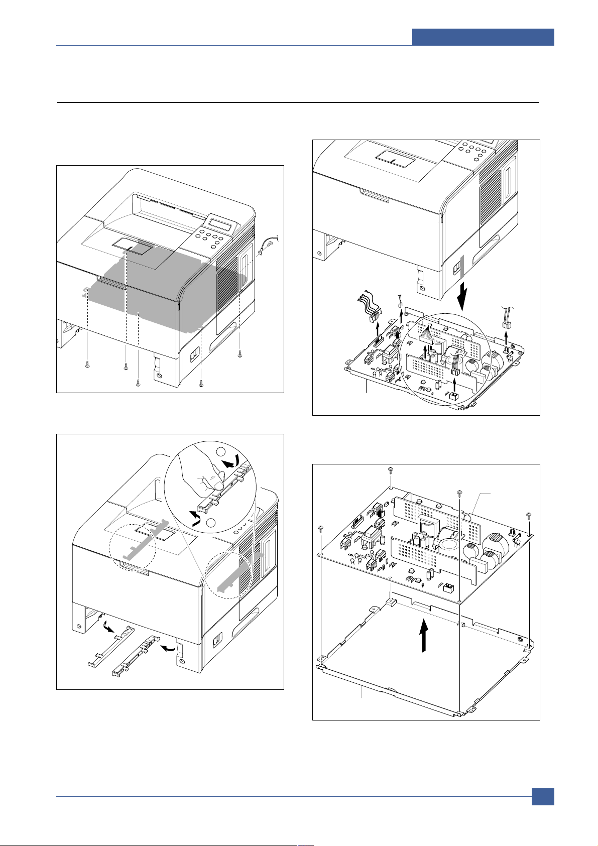
5.8 Main PBA
1. Before you remove the Main PBA, you should
remove: - Cover Right (Refer to the 5.7)
2. Unplug the all Connectors, as shown below.
3. The Connectors are located, as shown below.
4. Remove two screws and take out the Dummy
Bracket.
5. Remove six screws and take out the Main PBA.
Duplex
SMPS/HVPS
PBA
PTL
Cover Open
Thermistor
LSU
Toner
Sensor
DEVE
Motor
DPX_SOL
Key Panel
HDD(Optional)
Network
Card
Main Motor
Exit Sensor
Connector
PBA
Memory(Optional)
USB
Port
P1284
Port
SCF
Key Panel
Dummy
Bracket
Main PBA
Page 46

Disassembly and Reassembly
Service Manual
5-9
Samsung Electronics
5.9 Main Drive Ass'y
1. Before you remove the Main Drive Ass'y, you should
remove : - Cover Right (Refer to the 5.7)
2. Unplug the two Connectors from the Main Motor Ass'y
and the Connector PBA.
3. Remove the E-ring and take out the Clutch.
4. Remove six screws and take out the Main Drive
Ass'y .
5. When separating the Main Motor Ass'y , disconnect
the Connector from the Main Motor Ass'y , remove four
screws, and then remove the Main Motor Ass'y.
Connector
PBA
Main Drive
Ass’y
Clutch
E-Ring
Main Motor
Ass’y
Page 47

Service Manual
Disassembly and Reassembly
5-10
Samsung Electronics
5.10 DEVE Drive Ass'y
1. Before you remove the DEVE Drive Ass'y, you should
remove : - Cover Right (Refer to the 5.7)
2. Unplug the Connector from the DEVE Motor Ass'y.
3. Remove four screws and take out the DEVE Drive
Ass'y .
4. When separating the DEVE Motor Ass'y, disconnect
the Connector from the DEVE Motor Ass'y, remove
four screws, and then remove the DEVE Motor Ass'y.
DEVE Drive
Ass’y
DEVE Motor
Ass’y
Page 48

Disassembly and Reassembly
Service Manual
5-11
Samsung Electronics
5.11 Connector PBA
1. Before you remove the Connector PBA, you should
remove : - Cover Right (Refer to the 5.7)
2. Unplug the all Connectors from the Connector PBA
and take it out.
3. The Connectors are located, as shown below.
Connector
PBA
MP Solenoid
Cassette
Open S/W
Main Solenoid
Main PBA
Main Clutch
MP Empty
Page 49

Service Manual
Disassembly and Reassembly
5-12
Samsung Electronics
5.12 Solenoid
1. Before you remove the Solenoid, you should remove:
- Cover Right (Refer to the 5.7)
- Main Drive Ass'y (Refer to the 5.9)
2. Unplug the MP Solenoid Harness and the Main
Solenoid Harness from the Connector PBA.
3. Remove one screws and take out the MP Solenoid.
4. Remove one screws and take out the Main Solenoid.
*NOTICE : It is not necessary to disassemble the Main Drive
Ass'y to remove the MP Solenoid.
MP Solenoid
Main Solenoid
MP Solenoid
Connector PBA
Main Solenoid
Page 50

Disassembly and Reassembly
Service Manual
5-13
Samsung Electronics
5.13 Rear Cover
1. Open the Rear Cover, and then take out the Stopper . 2. Remove the Rear Cover in the direction of arrow
2
1
ie Stopper
Rear Cover
1
2
Page 51

Service Manual
Disassembly and Reassembly
5-14
Samsung Electronics
5.14 Cover Left
1. Pull the Cassette out of the printer.
2. Remove two screws and take out the left side.
3. Take out the Cover Left.
Cassette
Cover-Left
Page 52

Disassembly and Reassembly
Service Manual
5-15
Samsung Electronics
5.15 Top Cover
1. Before you remove the Top Cover, you should
remove:
- Rear Cover (Refer to the 5.14)
- Cover Right (Refer to the 5.7)
- Cover Left (Refer to the 5.13)
2. Open the MPF Ass'y, the Rear Cover, the Open Cover.
3. Unplug the two Connectors after you remove the
three screws from the Main PBA.
4. Unlatch both ends of the T op Cover .
5. Unlatch the hook and take out the Top Cover .
Open Cover
MPF Ass’y
Key Panel
Page 53

Service Manual
Disassembly and Reassembly
5-16
Samsung Electronics
6. Remove six screws and then take out the LCD Panel
and the Key Panel.
LCD Panel
Key Panel
5.16 Open Cover
1. Before you remove the Open Cover, you should
remove:
- Top Cover (Refer to the 5.15)
2. Remove two screws and take out the Stopper.
3. Take out the Open Cover, as shown below.
Stopper
Open Cover
Page 54

Disassembly and Reassembly
Service Manual
5-17
Samsung Electronics
5.17 Inner Cover
1. Before you remove the Inner Cover, you should
remove:
-MPFAss'y (Refer to the5.3)
- Top Cover (Refer to the 5.15)
2. Remove two screws and take out the Inner Cover.
Inner Cover
Page 55

Service Manual
Disassembly and Reassembly
5-18
Samsung Electronics
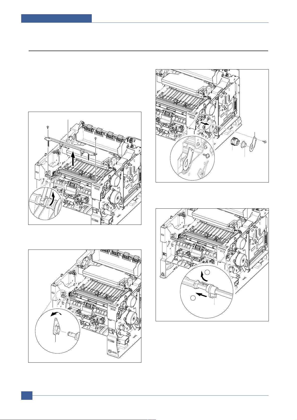
5.18 Fuser Ass'y
1. Before you remove the Fuser Ass'y, you should
remove:
- Rear Cover (Refer to the 5.14)
2. Pull the Locking Lever. Then take out the Fuser Ass'y,
as shown below.
3. Remove two screws and take the Thermostat out of
the Fuser Ass'y.
4. Remove two screws securing the Electrode L, R and
remove it, as shown below.
5. Remove two screws securing the Fuser Upper Unit
and remove it, as shown below.
Thrmistor
Connector
Fuser Ass’y
Harness L
Bush
Electrode
Harness R
Thermostat
Fuser Upper Unit
1
2
Fuser Lower Unit
Page 56

Disassembly and Reassembly
Service Manual
5-19
Samsung Electronics
6. Remove two screws securing the Release Lever L,R
and remove it, as shown below.
7. Remove two screws and take out the Gear Bracket.
8. Take out the Heat Roller Ass'y, as shown below.
9. Remove the screw securing the Thermistor and
remove it, as shown below.
Gear Bracket
Release Lever L
Pressure Roller
Cover-Fuser Lower
Release Lever R
Cover-Fuser Upper
Bearing
Heat Roller Ass’y
Fuser Gear
Thermistor
Page 57

Service Manual
Disassembly and Reassembly
5-20
Samsung Electronics
5.19 Duplex Solenoid Ass'y
1. Before you remove the Exit Solenoid Ass'y, you
should remove:
- Top Cover (Refer to the 5.15)
2. Unplug the Duplex Solenoid Harness from the Main
PBA.
3. Remove three screws and take out the Exit Solenoid
Ass'y .
4. Remove spring pin and remove two screws and take
out the Exit Solenoid.
Duplex Solenoid
Spring pin
Duplex
Solenoid
Duplex Solenoid
Ass’y
Page 58

Disassembly and Reassembly
Service Manual
5-21
Samsung Electronics
5.20 Exit Roller
1. Before you remove the Exit Roller, you should
remove:
- Top Cover (Refer to the 5.15)
2. Take out the Actuator.
3. Remove the Exit Roller and Bearing, as shown below.
4. Release the Exit Gear, as shown below.
5. Remove the Duplex Exit Roller as same method.
6. Release the Duplex Exit Gear, as shown below.
Exit Gear
Bearing
2
1
Actuator
Duplex
Exit Roller
Bearing
Exit Roller
Rack-Exit Roller
Bearing
Holder
Bearing
1
2
Duplex Exit Gear
Page 59

Service Manual
Disassembly and Reassembly
5-22
Samsung Electronics
1. Before you remove the LSU, you should remove:
- Rear Cover (Refer to the 5.14)
- Cover Right (Refer to the 5.7)
- Cover Left (Refer to the 5.13)
- Top Cover (Refer to the 5.15)
2. Remove the Cover-Frame Exit and unplug the
Connector from the Main PBA, as shown below.
3. Remove three screws and take out the LSU.
Cover Frame Exit
LSU
5.21 LSU
LSU
Page 60

Disassembly and Reassembly
Service Manual
5-23
Samsung Electronics
5.22 DC Fan
1. Before you remove the DC Fan, you should remove:
- Cover Right (Refer to the 5.7)
- Cover Left (Refer to the 5.13)
- Cover Rear (Refer to the 5.14)
2. Unplug the two Connectors from the Toner Sensor
PBA.
3. Remove the screw for taking out the Stopper , and
then take out the DC Fan.
Toner Sensor
PBA
Out Full
DC Fan
DC Fan
Stopper
Page 61

Service Manual
Disassembly and Reassembly
5-24
Samsung Electronics
5.23 Toner Sensor PBA
1. Before you remove the LSU, you should remove:
- Top Cover (Refer to the 5.15)
- LSU (Refer to the 5.21)
2. Unplug the all Connectors from the Toner Sensor
PBA.
3. Remove two screws and take out the Toner Sensor PBA.
4. Remove the screw securing the Cover Open PBA
and remove it. Then unplug the Connector from the
Main PBA, as shown below.
5. Remove three screws and take out the LSU Lower
Cover.
Cover Open PBA
Harness Cover
Cover Open
Toner Sensor
PBA
HV Small
Spring
Toner Sensor PBA
LSU Lower
Cover
Page 62

Disassembly and Reassembly
Service Manual
5-25
Samsung Electronics
5.24 REGI Ass'y
1. Before you remove the REGI Ass'y , you should
remove:
- Top Cover (Refer to the 5.15)
2. Unplug the Harness and remove four screws, as
shown below.
3. Release the lock as shown below and lift up the Gear
Cap.
4. Take out the REGI Ass'y, as shown below.
5. Unplug the Harness, remove the screw and take out
the PTL PBA.
REGI Ass’y
PTL Upper
Terminal
PTL PBA
Gear Cap
PTL PBA
Page 63
Service Manual
Disassembly and Reassembly
5-26
Samsung Electronics
5.25 MP Pick Up Ass'y
1. Before you remove the MP Pick Up Ass'y, you should
remove:
- MPFAss'y (Refer to the5.3)
- Main Drive Ass'y (Refer to the 5.9)
- Top Cover (Refer to the 5.15)
- Inner Cover (Refer to the 5.17)
2. First of all remove two screws. Lift up the MP Pick Up
Shaft for taking out the MP Pick Up Rack.
3. Remove the locking equipment rotate the Bearing in
the direction of arrow.
4. Remove the screw securing the Bracket and remove
the Gear Ass'y, as shown below.
5. Slide the Cam to the right by pulling on the MP Pick
Up Shaft, as shown below.
Gear ass’y
Bearing
Bracket
MP Pick Up Rack
Bearing
1
2
Idle-Cam
Page 64

Disassembly and Reassembly
Service Manual
5-27
Samsung Electronics
6. First lift the left side of the Shaft and then remove the
Shaft.
7. Push the Idle toward the ends of Shaft then take out
the Housing, as shown below.
Idle
Housing
1
2
1
1
2
Page 65

Service Manual
Disassembly and Reassembly
5-28
Samsung Electronics
5.26 Pick Up & Feed2 Assy
1. Before you remove the Pick Up Ass'y, you should
remove:
- Main Drive Ass'y (Refer to the 5.9)
- Right Cover (Refer to the 5.7)
2. Remove the Gear-Pick Up Cam, as shown below.
3. Remove the locking equipment rotate the Bearing in
the direction of arrow, as shown below.
4. Release the Pick Up Gear and remove the locking
equipment rotate the Bearing in the direction of arrow,
as shown below.
5. Remove four screws securing the Bottom Cross Bar
and remove it.
Bearing
1
2
Feed2 Gear
2
1
Gear-Pick Up Cam
Bearing
Retard Idle
Gear
Battom Cross Bar
Page 66

Disassembly and Reassembly
Service Manual
5-29
Samsung Electronics
6. Remove the Actuator as shown below .
7. Remove four screws securing the Guide-P-Front.
Then take out the Pick Up Unit, as shown below.
8. Remove two screws securing the Guide-M-Support
and remove it.
9. Remove the Feed1 Ass'y, as shown below.
10. Remove the Feed2 Ass'y, as shown below.
Guide-M-Support
Guide-P-Front
Actuator
2
1
Bushing Feed
Guide-M-Support
Pick Up Unit
3
2
2
1
Pickup Roller
Ass’y
1
Bearing
E-ring
Shaft
Ground-P-Pickup
1
Feed1 Roller
Ass’y
Bearing
2
Guide-M-Support
Shaft
Page 67

Service Manual
Disassembly and Reassembly
5-30
Samsung Electronics
1 1. Remove four screws securing the Feed2 Unit and
remove it, as shown below.
12. Remove the Roller Unit, as shown below.
Pick Up Frame
Roller Unit
Feed2 Unit
Page 68
Disassembly and Reassembly
Service Manual
5-31
Samsung Electronics
5.27 Engine Shield
1. Remove the Guide-P-Front.(Refer to the 5.16.7)
2. Remove six screws and slightly lift the Engine Shield,
as shown below.
3. Remove the Duplex Guide L, R, as shown below.
4. Unplug the all Connectors from the Engine PBA.
Then take out the Engine Shield Ass'y .
5. Remove four screws and take out the Engine PBA
out of the Shield.
Engine Shield Ass’y
Engine Shield
Ass’y
2
1
Guide-Duplex L
Guide-Duplex R
Engine PBA
Shield
Page 69

Alignment & Adjustments
Service Manual
6-1
Samsung Electronics
6
6
6. Alignment and Adjustments
This chapter describes the main functions for service, such as the product maintenance
method, the test output related to maintenance and repair, DCU using method, Jam removing
method, and so on. It includes the contents of manual.
6.1 How to use EDC (Engine Diagnostic Control) Mode
6.1.1 EDC Setup
EDC(Engine Diagnostic Control, EDC will be used below) is considered to test and check whether each functions of
machinery and h/w module are normal or not. All of the test function are able to be controlled by the keys and LCD
window on the panel without any other kits. It’s developed for related engineers, not for users.
Press ’OK’key & Power On
Diagnostic Mode
Press Menu Key
"MENU" key
1
[Main Menu] "OK" key
Option Interface
[Function] Tray3 Interface
Tray3 Interface "OK" key Pass (Fail):Vx.x.x
"Arrow" key
"CANCEL" key
"CANCEL" key
"Arrow" key
[Function] Duplex Interface
Pass (Fail):Vx.x.x
Duplex Interface "OK" key
2
[Main Menu] "OK" key
Test Pattern
[Function]
Simplex Printing
Test : Simplex? "OK" key "OK" key
"Arrow" key
"Arrow" key
[Function]
Duplex Printing
Test : Duplex? "OK" key "OK" key
Printing...[PageNum]
Engine Diagnostic Control UI Flow Chart
Page 70

Service Manual
Alignment & Adjustments
6-2
Samsung Electronics
"CANCEL" key
"OK" or "CANCEL" key
"CANCEL" key
3
[Main Menu] "OK" key
Motor & Fan
[Function] Main Motor
Main Motor "OK" key Running Test On/Off
"Arrow" key
"Arrow" key
[Function] Dev. Motor
Dev. Motor "OK" key Running Test On/Off
[Function] Laser Motor
Laser Motor "OK" key Running Test On/Off
[Function] Duplex Motor
Duplex Motor "OK" key Running Test On/Off
[Function] Tray3 Motor
Tray3 Motor "OK" key Running Test On/Off
[Function] Main Fan
Fan-Main "OK" key Running Test On/Off
[Function] SMPS Fan
Fan-Smps "OK" key Running Test On/Off
[Function] Duplex Fan
Fan-Duplex "OK" key Running Test On/Off
4
[Main Menu] "OK" key
Solenoid/Clutch
[Function] Tray1 Solenoid
ON/OFF
Tray1 Solenoid "OK" key
"Arrow" key
"Arrow" key
[Function] Tray2 Solenoid
ON/OFF
Tray2 Solenoid "OK" key
[Function] Tray3 Solenoid
ON/OFF
Tray3 Solenoid "OK" key
[Function] Regi. Clutch
ON/OFF
Regi. Clutch "OK" key
[Function] Duplex Solenoid
ON/OFF
Duplex Solenoid "OK" key
[Function] Tray3 Clutch
ON/OFF
Tray3 Clutch "OK" key
Page 71

Alignment & Adjustments
Service Manual
6-3
Samsung Electronics
5
[Main Menu] "OK" key
Sensors
[Function] T2 Paper : Letter
Paper Size Sensor "OK" key T3 Paper : A4
"Arrow" key
"Arrow" key
[Function] T1 Paper Sensor
Tray1 NP Sensor "OK" key With (W/O Paper)
[Function] T2 Paper Sensor
Tray2 NP Sensor "OK" key With (W/O Paper)
[Function] T3 Paper Sensor
Tray3 NP Sensor "OK" key With (W/O Paper)
[Function] Duplex Sensor
Duplex Sensor "OK" key With (W/O Paper)
[Function] Cover Sensor
Cover Open Sensor "OK" key Opened(Closed)
[Function] Feed Sensor
Feed Sensor "OK" key With (W/O Paper)
[Function] Exit Sensor
Exit Sensor "OK" key With (W/O Paper)
[Function] Out Bin
Full(not Full)
Output Sensor "OK" key
6
[Main Menu] "OK" key
HVPS
[Function] Dev Bias DC
Dev Bias DC "OK" key ON (OFF)
"Arrow" key
"Arrow" key
[Function] Dev Bias AC
Dev Bias AC "OK" key ON (OFF)
[Function] Charge Roll Volt
Charge Roll Volt "OK" key ON (OFF)
ON (OFF)
[Function] Transfer Roll(+)
Transfer Roll(+) "OK" key
"CANCEL" key
[Function] Fuser Door Sensor
Opened (Closed)
Fuser Door Sensor "OK" key
Page 72

Service Manual
Alignment & Adjustments
6-4
Samsung Electronics
"CANCEL" key
"CANCEL" key
"CANCEL" key
"CANCEL" key
ON (OFF)
[Function] Transfer Roll(-)
Transfer Roll(-) "OK" key
[Function] Pre Trans. Lamp
Pre Trans. Lamp "OK" key ON (OFF)
7
[Main Menu]
Laser Scanning
"OK" key
[Function] Laser Diode 0
Laser Diode 0 "OK" key ON (OFF)
"Arrow" key
"Arrow" key
[Function] Laser Diode 1
Laser Diode 1 "OK" key ON (OFF)
[Function] L Motor & Ready
L Motor & Ready "OK" key Pass (Fail)
8
[Main Menu] "OK" key
Fuser
[Function] Fuser Temp.
"Arrow" key Fuser Control "OK" key T:170, C:xxx
9
[Main Menu] "OK" key
OPC Cycle
[Function] Total OPC Cycle
"Arrow" key Read OPC Cycle "OK" key xxxx
1
[Main Menu]
Option Interface
Page 73

Alignment & Adjustments
Service Manual
6-5
Samsung Electronics
6.1.2 Entrance method for EDC
In order to enter the “EDC” mode, the entering method should be special because this mode is developed for the related
engineers, not for end users.
- Entering the mode, the message, “Diagnostic Mode (Top Line)” is displayed.
- In this mode, an operator should press the ‘Menu’ Key to search each function he would like to test.
• Usage
1. Checking whether printer is powered off or not.
2. Pressing the ‘OK’key and turn on the power.
3. Continue to press the button until the message “Diagnostic Mode” is displayed.
4. Wait until the message “Press Menu key” is displayed. And then when the message is displayed, press the ‘Menu’ key.
5. Ausage method for a function you would like to test is following.
6.1.3 Interface (Options)
This function is to check a communication state between the main controller and the option controller.
• Usage
1. Press the Arrow Keys ( / ) until finding [Main Menu]/ Option Interface message on the panel.
2. Press the OK Key for executing this function, when it is found.
3. Searching the sub function for testing by Arrow Key.
4. When the desired function is found, press the OK key to test.
5. The sub function is following.
- [Function]/MANUAL TRAY Interface
- [Function]/Duplex Interface
• Function
* The procedure and content above can be changed according to the situation.
Function Name Description Display(LCD) Remarks
Optional Tray
Interface
After it is in the correct mode, a message is
displayed on the panel.
If the I/F is normal, Pass message will be
displayed and abnormal, Fail displayed.
Pass (Fail): x.x.x
Tray3
Xs are
version.
Duplex
Interface
After it is in the correct mode, a message is
displayed on the panel.
If the I/F is normal, Pass message will be
displayed and abnormal, Fail displayed.
Duplex Interface Pass
(Fail):x.x.x
Xs are
version.
Page 74

Service Manual
Alignment & Adjustments
6-6
Samsung Electronics
6.1.4 Test pattern and paper path
- This function is to check a total print process state for engine side.
- In the EDC mode, a test pattern can be printed. While the printing job is processing, a location of a paper is continuously displayed on LCD.
• Usage
1. Press the Arrow Keys ( / ) until finding [Main Menu]/ Print Pattern message on the panel.
2. Press the OK Key , when it is found.
3. Searching the sub function for testing by Arrow key
4. When the desired function is found, press the OK key to test.
5. The sub function is following.
- [Function]/Simplex Print
- [Function]/Duplex Print
• Function
If printing the test image, the printer continues to print the test image until pressing the stop button.
* The procedure and content above can be changed according to the situation.
6.1.5 Motor and Fan
These functions are to check a current status (normal or not) of the motors and the fans.
• Usage
1. Press the
Arrow Keys ( / ) until finding [Main Menu]/ Motor/ Fan at main menu mode.
2. Press the
OK key, when it is found.
3. Searching the sub function for testing by Arrow key
4. Press the OK key, when it is found.
5. Press the OK key for execution or the Cancel key for stop for the selected sub function.
6. The sub function is following.
- [Function]/Main Motor
- [Function]/Dev. Motor
- [Function]/Laser Motor
- [Function]/Duplex Motor
Function Name Description Display(LCD) Remarks
Simplex Print When the operator selects this mode, the page is
printed out by simplex mode.
Simplex Print <Example>
Simplex Print
Duplex Print When the operator selects this mode, the page is
printed out by duplex mode.
Duplex Print <Example>
Duplex Print
Page 75

Alignment & Adjustments
Service Manual
6-7
Samsung Electronics
- [Function]/MANUAL TRAY Motor
- [Function]/Main Fan
- [Function]/Cru Fan
- [Function]/SMPS Fan
- [Function]/Duplex Fan
• Function
* The procedure and content above can be changed according to the situation.
Function Name Description Display(LCD) Remarks
Main Motor When the operator executes this function by pressing
OK key , the main motor is running, and it is stopped
when Cancel key is pressed.
Main Motor
Running Test On/Off
Dev Motor When the operator executes this function by pressing
OK key , the Dev motor is running, and it is stopped
when Cancel key is pressed.
Dev Motor
Running Test On/Off
Laser Motor The laser motor function processes just like the main
motor function.
Laser Motor Running
Test On/Off
Duplex Motor The Duplex motor function processes just like the
main motor function.
Duplex Motor
Running Test On/Off
Optional Tray
Motor
The MANUAL TRAY motor function processes just like
the main motor function.a When a MANUAL TRAYis
not installed, this function is not processed and Tray3
Not Installed is shown.
Tray3
Motor Running T est
On/Off
Main Fan When the operator executes this function by pressing
OK key , the main fan is running, and it is stopped
when Cancel key is pressed.
Main Fan
Running Test On/Off
SMPS Fan When the operator executes this function by pressing
OK key , the SMPS fan is running, and it is stopped
when Cancel key is pressed.
Smps Fan
Running Test On/Off
Duplex. Fan The duplex-fan function processes just like the fan-
main function.
Duplex Fan
Running Test On/Off
Page 76

Service Manual
Alignment & Adjustments
6-8
Samsung Electronics
6.1.6 Solenoid and Clutch
These functions are to check a current state (normal or not) of the solenoids and clutches.
• Usage
1. Press the Arrow Keys ( / ) until finding [Main Menu]/ Solenoid/Clutch message on the panel.
2. Press the OK Key , when it is found.
3 Searching the sub function for testing by Arrow key
4. Press the OK key, when it is found.
5. Press the OK key for execution or the Cancel key for stop for the selected sub function.
6. The sub function is following.
- [Function]/Tray1 Solenoid
- [Function]/MP Tray Solenoid
- [Function]/MANUAL TRAYSolenoid
- [Function]/Regi. Clutch
- [Function]/ Duplex Solenoid
- [Function]/ MANUAL TRAYClutch
• Function
* The procedure and content above can be changed according to the situation.
Function Name Description Display(LCD) Remarks
Tray1 Solenoid When the operator executes this function, the Tray1
Solenoid is turned on for 200ms, and then it is automatically stopped.
Tray1 Solenoid
ON/OFF
MP Tray
Solenoid
When the operator executes this function, the MP Tray
Solenoid is turned on for 200ms, and then it is automatically stopped.
MP Tray Solenoid
ON/OFF
Optional Tray
Solenoid
When the operator executes this function, the MANUAL TRAYsolenoid is turned on for 200ms, and then it
is automatically stopped. a When the MANUALTRAY
is not installed, this function is not processed and
Tray3 Not installed is shown
Tray3
Solenoid ON/OFF
Regi. Clutch When the operator executes this function, the Regi
Clutch is turned on for 200ms, and then it is automatically stopped.
Regi. Clutch ON/OFF
Duplex Solenoid When the operator executes this function, the Duplex
Solenoid is turned on for 200ms, and then it is automatically stopped.
Duplex Solenoid
ON/OFF
Optional Tray
Clutch
When the operator executes this function, the
Optional Tray Clutch is turned on for 200ms, and then
it is automatically stopped.
Tray3
Clutch ON/OFF
Page 77

Alignment & Adjustments
Service Manual
6-9
Samsung Electronics
6.1.7 Sensors
These Functions are to check a current state (normal or not) of the Sensors.
• Usage
Paper Size Sensor
1. Press the Arrow Keys ( / ) until finding [Main Menu]/ Sensors message on the panel.
2. Press the OK Key , when it is found.
3. Press the Arrow keys until finding [Function]/ Paper Size Sensor .
4. Press the OK Key , when it is found.
5. Pull out a tray (2 or 3, not 1) you would like to test.
6. Check the message, MPTray: Out (MANUAL TRAY: Empty/Out) is displayed.
7. Fill the tray with one or more papers.
8. Put the tray back.
9. Check the message on the LCD window.
(The top line for MP Tray and the bottom line for MANUAL TRAY)
10. Compare the paper message on the window with the real paper size.
The other sensors
1. Press the Arrow Keys ( / ) until finding [Main Menu]/ Sensors message on the panel.
2. Press the OK Key for executing this function, when it is found.
3. Searching the sub function for testing by Arrow key
4. Press the OK key, when it is found.
5. The sub function is following.
- [Function]/Tray1 Paper Sensor
- [Function]/MP Tray Paper Sensor
- [Function]/Manual Tray Paper Sensor
- [Function]/ Duplex Sensor
- [Function]/ Cover Sensor
- [Function]/ Feed Sensor
- [Function]/ Exit Sensor
- [Function]/ Output Bin Sensor
- [Function]/ MP Tray Out Sensor
- [Function]/ Manual Tray Out Sensor
- [Function]/Fuser Door Sensor
6. Check the message that is displayed on the LCD window for the state of each sensor as touching the sensor s
actuator.
Page 78

Service Manual
Alignment & Adjustments
6-10
Samsung Electronics
• Function
Paper Size Sensor
The other sensors
Sensor Description Example Remarks
Message Real Paper
Paper Size
Sensor
After a tray is filled with papers, confirm the
paper size and compare it with the real size.
MP Tray: Letter
Manual Tray: LEGAL
Letter
LEGAL
Sensor Description Display (LCD) Remarks
Before touching After touching
Tray1 Paper
Sensor
After the tray 1 is pulled out, touch the
sensor and confirm the message is changed or
not.
Tray1 Paper
Sensor W/Out
Paper
Tray1 Paper
Sensor With
Paper
MP Tray
Paper Sensor
After the MP Tray is pulled out, touch the
sensor and confirm the message is changed or
not.
MP Tray Paper
SensorW/Out
Paper
MP Tray Paper
SensorWith
Paper
Duplex
Sensor
After the back cover is opened, push a paper
into the duplex path and confirm the message is
changed or not.
Duplex Sensor
W/Out Paper
Duplex
Sensor With
Paper
Cover
Sensor
After the cover is open, touch the sensor and
confirm the message is changed or not.
Cover Sensor
Opened
Cover Sensor
Closed
Feed
Sensor
After the cover is open and the toner
cartridge is out, touch the sensor and
confirm the message is changed or not.
Feed Sensor
W/Out Paper
Feed Sensor
With Paper
Exit Sensor After the back cover is open, push a paper into
the exit path and confirm the message is
changed or not.
Exit Sensor
W/Out Paper
Exit Sensor
With Paper
Out
BinSensor
Touch the sensor in the output Bin and confirm
the message changed.
Output Bin Not
Full
Output Bin Full
MP Tray
Out Sensor
Remove the MP Tray and confirm the message
changed.
MP Tray In MP Tray Out
Manual Tray
Out Sensor
Remove the MANUAL TRAYand confirm the
message changed.
Manual Tray In Manual Tray
Out
Page 79

* The procedure and content above can be changed according to the situation.
6.1.8 HVPS
These functions are to check whether the control for HVPS is normal or not.
• Usage
1. Press the Arrow Keys ( / ) until finding [Main Menu]/ HVPS message on the panel.
2. Press the OK Key , when it is found.
3. Searching the sub function for testing by Arrow key
4. Press the OK key, when it is found.
5. The sub function is following.
- [Function]/Dev. Bias DC
- [Function]/Dev. Bias AC
- [Function]/Charge Roll Volt
- [Function]/Transfer Roller(+)
- [Function]/Transfer Roller(-)
- [Function]/Pre Trans. Lamp
6. Press the OK Key for executing or the Cancel key for stopping of the sub function.
Alignment & Adjustments
Service Manual
6-11
Samsung Electronics
Sensor Description Display (LCD) Remarks
Before touching After touching
Fuser Door
Sensor
After the rear cover is open, touch the fuser
door sensor and confirm the message.
Fuser Door
Senor Closed
Fuser Door
Senor
Opened
Page 80

• Function
* The procedure and content above can be changed according to the situation.
Service Manual
Alignment & Adjustments
6-12
Samsung Electronics
Function Name Description Display(LCD) Remarks
Dev Bias DC Dev bias DC is supplied after the execution (link with
OK Button) key is chosen and stops when the Cancel
Button is chosen.
Dev Bias DC
On / Off
Dev Bias AC Dev bias AC is supplied after the execution (link with
OK button key is chosen and stops when the Cancel
button is chosen.
Dev Bias AC
On / Off
Charge Roll
Voltage
Charge roller voltage is supplied after the
execution (Link with OK button) key is chosen and
stops when the Cancel button is chosen.
Charge Roll Volt
On / Off
Transfer Roller
(+)
Transfer positive voltage is supplied after the OK button is chosen and stops when the Cancel
button is chosen.
Transfer Roll(+)
On / Off[%d]
[%d] is the
value of the
ADC
Transfer Roll (-) Transfer negative voltage is supplied after the OK but-
ton is chosen and stops when the Cancel
button is chosen.
Transfer Roll (-)
On / Off
Pre Transfer
Lamp
The Pre-Transfer Lamp is on after the OK button is
chosen and stops when the Cancel button key is chosen. It is possible to confirm the lamp is on after the
cover is opened and the cartridge is removed.
Pre Trans. Lamp
On / Off
Page 81

6.1.9 Laser Scan Unit
These functions are to check a current state (normal or not) of the Laser Scanning Unit.
• Usage
1. Press the Arrow Keys ( / ) until finding [Main Menu]/ Laser Scanning message on the panel.
2. Press the OK Key , when it is found.
3. Searching the sub function for testing by Arrow key
4. Press the OK key, when it is found.
5. The sub function is following.
- [Function]/Laser Diode 0
- [Function]/Laser Diode 1
- [Function]/L Motor & Ready
6. Press the OK Key for executing or the Cancel key for stopping of the sub function.
• Function
* The procedure and content above can be changed according to the situation.
Alignment & Adjustments
Service Manual
6-13
Samsung Electronics
Function Name Description Display(LCD) Remarks
Laser Diode_0
Laser Diode0 On is displayed, when the laser diode
is on. On the other case Laser Diode0 Off is displayed.
Laser Diode0
On ( Off )
Laser Diode_1
Laser Diode1 On is displayed, when the laser diode
is on. On the other case Laser Diode1 Off is displayed.
Laser Diode1
On ( Off )
L Motor &
Ready
When Laser Scanning Unit is ready to print (Laser
diode on, Stable polygon motor speed) the
message, Laser Ready is displayed. On the other
case Laser Error
L Motor & Ready
Laser Ready
(Laser Error)
Page 82

Service Manual
Alignment & Adjustments
6-14
Samsung Electronics
6.1.10 Fuser
This function is to check a current state (normal or not) of the fuser.
• Usage
1. Press the Arrow Keys ( / ) until finding [Main Menu]/ Fuser message on the panel.
2. Press the OK Key , when it is found.
3. Confirm the message, [Function]/ Fuser Temp. .
4. Press the OK Key .
5. Set the temperature with arrow keys. (Default: 170 , Range: 150 -190 )
6. Press the OK Key for executing or the Cancel key for stopping this function.
7. Compare a target temperature with a real temperature.
• Function
* The procedure and content above can be changed according to the situation.
6.1.11 Opc Cycle
-This function is to check a total rotating number of OPC drum as of the entering point.
The entering point means the time when the power is on, not the initial point of the OPC Cycle test.
• Usage
1. Press the
Arrow Keys ( / ) until finding [Main Menu]/ OPC cycle message on the panel.
2. Press the OK Key , when it is found.
3. Confirming the
[Function]/ Read OPC cycle message, press the OK key .
4. Press the
Cancel key for stopping this function.
• Function
* The procedure and content above can be changed according to the situation.
Function Name Description Display(LCD) Remarks
Fuser Temp.
When Target Temp is displayed, Input a
temperature you would like to set with the arrow keys
( / ) and Press the Ok key . The target temperature and a real temperature will be
displayed on the bottom line.(Default T is 170)
Fuser Temp.
T: 170, C: XX
Function Name Description Display(LCD) Remarks
Read OPC
Cycle
A total rotating number of OPC drum is displayed on
the bottom line of LCD window, when the process is
on.
Total OPC-Cycle
XXXX
Page 83

Alignment & Adjustments
Service Manual
6-15
Samsung Electronics
6.2 Paper Path
❶ Cassette ❷ Duplex
❸ MPF ❹ Print Cartridge
❺ LSU ❻ Fuser
❼ SMPS & HVPS Board ❽ Duplex Solenoid
<Jam 0> <Jam 1>
Page 84

Service Manual
Alignment & Adjustments
6-16
Samsung Electronics
• Simplex
1) Apaper is fed from a cassette or MPF by a printing order.
2) The fed paper passes a paper feeding sensor.
- If the sensor does not operate after feeding the paper, the Jam0 occurs.
3) The paper passes a paper exit sensor, and it comes out from a machine.
- If the tailing edge of the paper does not come out from a machine after the leading edge
of the paper passes the sensor, then certain time later, a Jam2 occurs.
• Duplex
1) Apaper is fad from a cassette or MPF by a printing order.
2) The fed paper passes a paper feeding sensor.
- If the sensor does not operate after feeding the paper, a Jam0 occurs.
3) The paper that passes a paper exit sensor takes several printing processes, and moves to a
paper exit sensor.
- If the sensor does not operate after certain time, a Jam 1 occurs.
4) If the paper does not discharge until the paper passes an exit roller and a Roller-Exit-F/Down, a
Jam 2 occurs.
5) The printing paper starts to be printed for duplex only by reversing rotation by an exit motor. The
printing paper enters to a machine through an exit roller, and reaches to duplex sensor.
- If the printing paper cannot reach to the duplex sensor after certain time, a duplex Jam 1
occurs.
6) The printing paper that passes the duplex sensor reaches to a feed sensor again and a printing
operation is tried over again.
- If the printing paper cannot reach to a feed sensor after certain time later, a duplex Jam 2
occurs.
<Jam 2>
<Jam Duplex 1> <Jam Duplex 2>
Page 85

Alignment & Adjustments
Service Manual
6-17
Samsung Electronics
6.2.1 Clearing Paper Jams
When a paper jam occurs,the display on the control panel shows the message indicating the corresponding location of the
paper jam.
6.2.1.1 Tips for A voiding Paper Jams
By selecting the correct paper types, most paper jams can be avoided. If a paper jam occurs, follow the steps outlined in
• Ensure that the adjustable guides are positioned correctly.
• Do not overload the tray . Ensure that the paper is below the paper capacity mark on the right inside of the tray.
• Do not remove the paper from the tray while printing.
• Flex, fan and straighten the paper before loading.
• Do not use creased, damp or highly curled paper.
• Do not mix paper types in the input tray.
• Use only recommended print media.
• Ensure that the recommended print side is facing down when loading paper into the input tray.
6.2.1.2 In the Paper Feed Area(Jam 0)
• In the T ray1
1. Slide out the Tray1 to expose the jammed paper.
2. Remove any misfed paper by pulling it out by the visi ble edge from the tray.Make sure that all of the paper is
properly aligned in the tray .
NOTE : If the jammed paper is not invisible or if there is resis-
tance when you pull the paper,remove the tray from the
printer and carefully pull the jammed paper free from
the printer.
3. Slide the tray back into the printer.
4. Open and close the top cover to resume printing.
Page 86

Service Manual
Alignment & Adjustments
6-18
Samsung Electronics
• In the Optional MP Tray
1. Pull the optional MP Tray out of the printer.
2. If you see the jammed paper,remove the paper from
the tray.
3. If you cannot find the jammed paper in the MP Tray ,pull
the Tray1 half way out of the printer,and remove the
paper.
4. Slide the trays back into the printer. Open and close the
top cover.Printing can be resumed.
• In the Multi-Purpose Tray
1. Open the Multi-Purpose Tray.
2. Carefully remove the jammed paper from the tray.
3. Open and close the top cover.Printing can be resumed.
Page 87

Alignment & Adjustments
Service Manual
6-19
Samsung Electronics
6.2.1.3 Around the Print Cartridge (Jam1)
1. Open and close the top cover,and the jammed paper
should exit the printer.
If not,continue to Step 2.
2. Open the top cover and remove the print cartridge.
CAUTION : To prevent damage to the print cartridge,do not
expose it to light for more than a few
minutes.Place a piece of paper over the top of the
print cartridge to shield it while it is out of the printer.
3. Carefully lift up the guide feed.
4. Gently pull the jammed paper towards you to remove
it from the printer .
If the jammed paper is not visible or there is resistance when you pull the paper,go to “In the Paper Exit
Area ”.
5. Flip down the guide feed and reinstall the print
cartridge.
NOTE : If the print cartridge is difficult to reinstall,make sure
that the guide feed has been flipped back down into
position.
6. Close the top cover.Printing can be resumed.
Gu ide Feed
Page 88

Service Manual
Alignment & Adjustments
6-20
Samsung Electronics
NOTE
6.2.1.4 In the Paper Exit Area (Jam 2)
1. If a long portion of the paper is visible,pull it straight out.
If not,continue to Step 2.
2. Open the rear output tray.
3. Loosen the paper if it is caught in the feed rollers. Then
gently pull the paper out.
4. Close the rear output tray.
5 Open and close the top cover .Printing can be resumed.
>> In case the roller of fuser assembly is contaminated, clean it as follows
1. In case for Fuser Cleaning
Select as follows: Menu -> Setup -> Maintenance -> Fuser Cleaning
2.
In case for OPC Cleaning
Select as follows: Menu -> Setup -> Maintenance -> OPC Cleaning
>> If contamination is still found, do clean in accordance with above method several times.
Page 89

Alignment & Adjustments
Service Manual
6-21
Samsung Electronics
6.2.1.5 In the Duplex Area
• Duplex Jam 1
1. Open the rear output tray. 2. Remove the jammed paper.
3. Close the rear output cover.
4. Open and close the top cover .Printing can be resumed.
• Duplex Jam 2
1. Pull the duplex unit out of the printer . 2. Locate the jammed paper and remove it.
3. Insert the duplex unit into the slot.
4. Open and close the top cover. The printer will resume
printing.
Page 90

Service Manual
Alignment & Adjustments
6-22
Samsung Electronics
6.3 Sample Pattern
This product has the several sample patterns for maintenance. With the sample patterns, check the existence of the
abnormality. The patterns help to regularly maintain the product.
6.3.1 Information Pages
Your printer comes with a set of information pages that helps you solve printing problems and obtain the best results
from your printer. You can access these pages from the printer’s front panel.
To print information pages:
1. On the printer’s front panel, press the Menu button, then press the Enter button to select Information.
2. Select Info Pages, then press the Enter button.
Slect key( ), tind to intormation menu.
Press Enter key, sutch to intormation page.
Press Enter key, the printing.
* 3. Select the appropriate information page, then press the Enter button to print.
* If installed The HDD, select press(1~3 times), then display intormation menu.
Note : Print the “Menu Map” to see other information pages available for printing.
6.3.2 Demo Pages
Your printer comes with a set of sample pages which demonstrate different functions.
To print sample pages:
1. On the printer’s front panel, press the Menu button, then press the OK button to select Information.
2. Select Demo Pages, then press the OK button.
3. Select the desired sample page, then press the OK button to print.
Page 91

Alignment & Adjustments
Service Manual
6-23
Samsung Electronics
6.4 Periodic Defective Image
If the delinquent image regularly occurs in the printed-paper, it is due to delinquent or damaged roller.
Refer to the table in below and check the condition of the roller.
No Roller Defective image Typical defect
1 OPC Drum 95 mm white spot on black image or black spot
2 Charge Roller 38 mm black spot
3 Supply Roller 45 mm light or dark horizontal image band
4 Developing Roller 43 mm horizontal image band
5 Transfer Roller 55 mm image ghost
6 Heat Roller 126 mm Black spot and image ghost
7 Pressure Roller 126 mm black spot on the backside
OPC Drum
Charge Roller
Supply Roller
Developing Roller
Transfer Roller
Heat Roller
Pressure Roller
Cleaning Roller
1
2
3
4
5
6
7
8
<Rollers Layout>
Page 92

Troubleshooting
Service Manual
7-1
Samsung Electronics
7
7
7. Troubleshooting
7.1 The cause and solution of Bad image
7.1.1 Vertical Black Line and Band
• Description
1. Straight thin black vertical line occurs in the printing.
2. Dark black vertical band occur in the printing.
Digital Printer
Digital Printer
Digital Printer
Digital Printer
Digital Printer
Check and Cause Solution
1. Deformed Doctor-blade or cleaning-blade,
in print cartridge
2. Scratched surface of the charge roller in
the print cartridge.
3. Partly depression or deformation on the
surface of the transfer roller .
1. If causes 1 and 2 occur in the print
cartridge, replace the print cartridge and
try to print out.
2. Replace the transfer roller if occurred as
No. 3.
7.1.2 Vertical White Line
• Description White vertical voids in the image.
Digital Printer
Digital Printer
Digital Printer
Digital Printer
Digital Printer
Check and Cause Solution
1. Foreign matter stuck onto the window of
internal lenses of LSU mirror .
2. Foreign matter or toner particles between
the print cartridge roller and blade.
(In case the life of the print cartridge has
been expired, white lines or light image
occur in front of the image.)
3. It may occur when Burr and foreign
substances are on the window of the
print cartridge frame.
4. If the fuser is defective, voids occur
periodically at the top of a black image.
5. It may occur when foreign substances
are on the OPC Drum.
6. Partly depression or deformation on the
surface of the transfer roller
1. Foreign matter stuck onto the window :
Clean the LSU window with recommended cleaner(IPA) Clean the window with a
clean cotton swab.
2.. Replace the print cartridge.
3. No 3. : Remove the foreign matter and
burr of the exposure window.
(print cartridge)
4. No. 4. : Open the front cover and check
ribs that corresponds to the position of
the voids. Remove if found.
5. If the problems are not solved, replace
the print cartridge.
6. Replace the transfer roller if occured as
NO.6
Page 93

Service Manual
Troubleshooting
7-2
Samsung Electronics
7.1.3 Horizontal Black Band
• Description
1. Dark or blurry horizontal stripes occur in the printing periodically.
(They may not occur periodically.)
Digital Printer
Digital Printer
Digital Printer
Digital Printer
Digital Printer
Check and Cause Solution
1. Bad contacts of the voltage terminals to
print cartridge.
2. The rollers of print cartridge may be
stained.
Charge roller = 38mm
Supply roller = 45mm
Develop roller = 43mm
Transfer roller = 55mm
1. Clean each voltage terminal of the Charge,
Supply, Develop and Transfer roller.
(remove the toner particles and paper particles)
2. Clean the right Gear that has relatively
small gap of the teeth in the OPC.
3. If the malfunction persists, replace the
print cartridge.
7.1.4 Black/White Spot
• Description
1. Dark or blurry black spots occur periodically in the printing.
2. White spots occur periodically in the printing.
Digital Printer
Digital Printer
Digital Printer
Digital Printer
Digital Printer
Check and Cause Solution
1. If dark or blurry black spots occur periodically, the rollers in the print cartridge may
be contaminated with foreign matte or
paper particles.
( Charge roller : 38 mm interval
OPC drum : 95 mm interval)
2. If faded areas or voids occur in a black
image at intervals of 95 mm, or black
spots occur elsewhere, the OPC drum
surface is damaged.
3. If a black image is partially broken, the
transfer voltage is abnormal or the transfer roller's life has expired.
1. Run OPC cleaning Mode Print and run the
Self-test 2 or 3 times.
2. In case of 95 mm interval unremovable in
1, cleanly remove foreign substances stuck
on the OPC location equivalent to black
spots and white spots with a dry duster.
3. The transfer roller guarantees 150,000
sheets printing in normal environment. If
the roller's life is expired, replace it.
4. In case of 95 mm interval unremovable in
1, take measures as to replace the
print
cartridge and try to print out.
5. Clean the inside of the set against the
paper particles and foreign matter in order
not to cause the trouble.
Page 94

7.1.5 Light Image
• Description The printed image is light, with no ghost.
Digital Printer
Digital Printer
Digital Printer
Digital Printer
Digital Printer
Check and Cause Solution
1. Develop roller is stained when the toner
of print cartridge is almost consumed.
2. Ambient temperature is below than 10°C.
3. Bad contact caused by the toner stains
between the high voltage terminal in the
HVPS and the one in the set.
4. Abnormal output from the HVPS.
(Run self-test and check 1~4)
5. Check warranty out.
1. Check if the Toner Save mode is off.
Check if the density is light.
2. No 1 : R
eplace the print cartridge and try to
print out.
3. No 2 : Wait 30 minutes after printer is pow-
ered on before you start printing.
4. No3 : Clean up the contaminated area by
the toner.
5. Replace the HVPS if the problems are not
solved by the above four instructions.
6. Replace print cartridge.
7.1.6 Dark Image or a Black Page
• Description The printed image is dark.
Digital Printer
Digital Printer
Digital Printer
Digital Printer
Digital Printer
Check and Cause Solution
1. No charge voltage in the engine board.
2. Charge voltage is not turned on due to
the bad contacts between power supply
in the side of the print cartridge and
charge terminal of HVPS.
3. VD0 signal of the Main PBA is Low state.
4. Case back side the cleaning blade of
print cartridge.
1. Check the state of the connector which
connects the engine board and HVPS.
2. Clean the high voltage charge terminal.
3. Replace the HVPS if not solved by the
above direction 1 and 2.
4. Replace the LSU Unit or Main PBA.
5. Replace print cartridge.
Troubleshooting
Service Manual
7-3
Samsung Electronics
Page 95

Service Manual
Troubleshooting
7-4
Samsung Electronics
7.1.7 Uneven Density
• Description Print density is uneven between left and right.
Check and Cause Solution
1. The pressure force on the left and right
springs of the transfer roller is not even,
the springs are damaged, the transfer
roller is improperly installed, or the transfer roller bushing or holder is damaged.
2. The life of the print cartridge has expired.
3. The toner level is not even on the print
cartridge roller due to the bad blade.
1. Replace both the left and right Spring
Holder.
2. Occur in the print cartridge gently shake
the
print
cartridge.
3.Replace the
print
cartridge and try to print
out.
7.1.8 Background
• Description Light dark background appears in whole area of the printing.
Digital Printer
Digital Printer
Digital Printer
Digital Printer
Digital Printer
Check and Cause Solution
1.
Does character exist less than 2%
coverage per a page, and hasn’t it
been used long time?
(see the configuration sheet)
2.
Is a recycled print cartridge be used?
3.
Has the life span of the print
cartridge ended?
4.
Is the movement(Up and Down) of
the transfer roller smooth?
5. Is the HVPS normal?
1.
The
print
cartridge is basically
designed to print 12,000 pages with
5% coverage. If it prints more than
15,000 pages with 2% coverage, a
background can occur.
2.
The A/S is not guaranteed if using a
recyled the print cartridger.
3.
Replace the print cartridge when the
life span of it has been ended.
4.
Clean the bushing part of the transfer
roller.
5. If the problem is still not solved,
replace the print cartridge.
Page 96

Troubleshooting
Service Manual
7-5
Samsung Electronics
7.1.9 Ghost (1)
• Description Ghost occurs at 95 mm intervals of the OPC drum in the whole printing.
Digital Printer
Digital Printer
Digital Printer
Digital Printer
Digital Printer
Digital Printer
95 mm
Check and Cause Solution
1. Bad contacts caused by contamination
from toner particles between high voltage
terminal in the main body and the electrode of the
print
cartridge.
2. Bad contacts caused by contamination
from toner particles between high voltage
terminal in the main body and the one in
the HVPS board.
3. The life of
print
cartridge is expired.
4. Transfer roller lifetime(150,000 sheets)
has expired.
5. Abnormal low temperature(below 10°C).
6. Damaged cleaning blade in the
print
cartridge.
1. Clean the terminals when contaminated by
toner particles.
2. Occur in the
print
cartridge, replace the
print
cartridge and try to print out.
3. Replace the engine board if not solved by
the above directions 1-2.
4. If not solved by the direction 3, check the
transfer roller lifetime and replace it.
5. Wait about 1 hour after power on before
using printer.
6. Occur in the
print
cartridge, replace the
print
cartridge and try to print out.
7.1.10 Ghost (2)
• Description
Ghost occurs at 95 mm intervals of the OPC drum in the whole printing.
(When printing on card stock or transparencies using manual feeder)
Digital Printer
Digital Printer
Digital Printer
Digital Printer
Digital Printer
Digital Printer
95 mm
Check and Cause Solution
When printing on card stock thicker than nor mal paper or transparencies such as OHP,
higher transfer voltage is required.
Select Card stoc or OHP Film on paper type
menu from the software application and after
using returning to the original mode is
recommended.
Page 97

Service Manual
Troubleshooting
7-6
Samsung Electronics
7.1.11 Ghost (3) : Fuser
• Description Ghost occurs at 126 mm intervals.
Digital Printer
Digital Printer
Digital Printer
Digital Printer
Digital Printer
Digital Printer
126 mm
Check and Cause Solution
The temperature of the fuser is maintained
high.
1. Disassemble the fuser and remove the
contaminated toner particles on the roller
and clean the foreign matter between
Thermistor and Heat roller .
(Caution: can be deformed)
7.1.12 Stains on the Face of Page
• Description The background on the face of the printed page is stained.
Digital Printer
Digital Printer
Digital Printer
Digital Printer
Digital Printer
Check and Cause Solution
1. Toner leakage due to improperly sealed
print cartridge.
2. If the transfer roller is contaminated, stains
on the face of page will occur.
1. Replace the
print
cartridge, and clean to
the toner powder of machine.
2. If the transfer roller is contaminated, run
OPC Cleaning Mode Print 2 or 3 times.
And perform Self-Test 2 or 3 times to
remove contamination.
Page 98
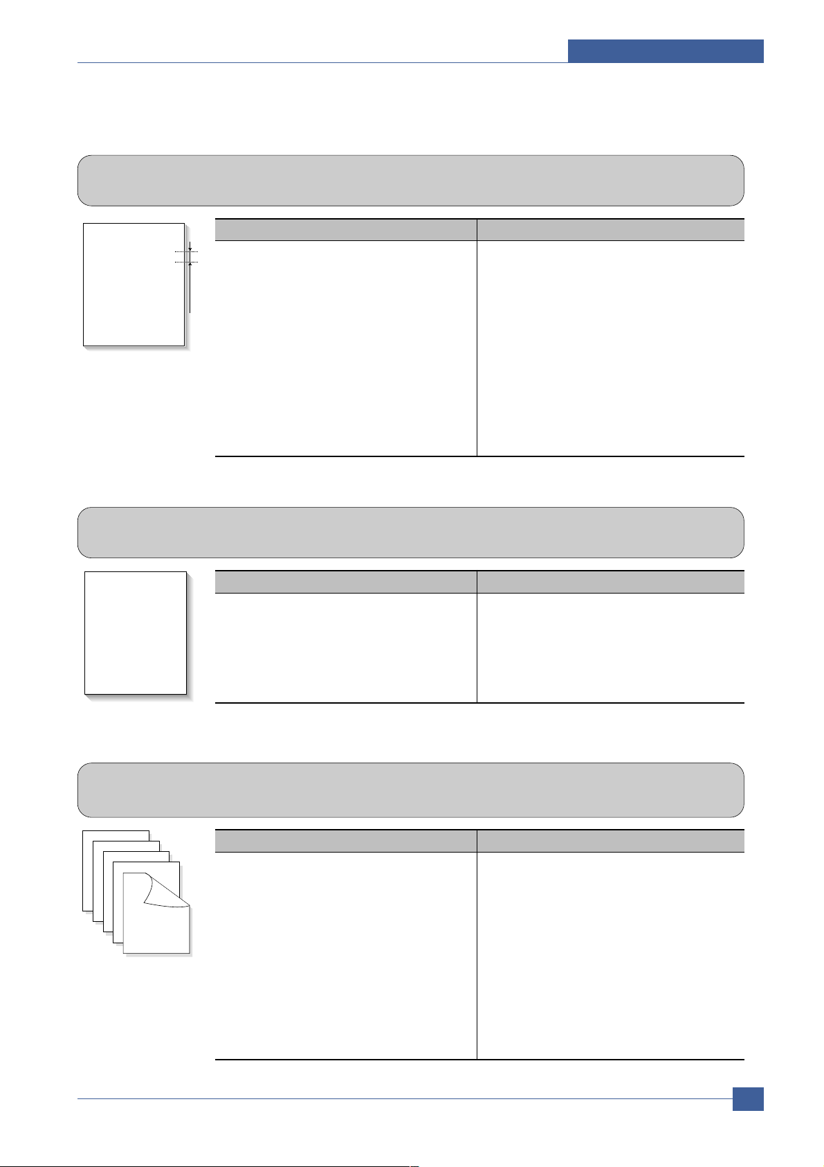
Troubleshooting
Service Manual
7-7
Samsung Electronics
7.1.13 Stains on Back of Page
• Description The back of the page is stained at 55 or 126 mm intervals.
Digital Printer
Digital Printer
Digital Printer
Digital Printer
Digital Printer
Digital Printer
55 or 126 mm
Check and Cause Solution
1. 55mm : Transfer roller is contaminated.
2. 126mm : Pressure roller is contaminated.
1. Perform the OPC Cleaning Mode Print 2 or
3 times. Run Self-Test to remove the contamination of the transfer roller.
2. Replace the transfer roller if contaminated
severely .
3. Disassemble the fuser and clean the
H/R(Heat Roller) and P/R(Pressure roller).
And check the area between H/R and
Thermistor. If contaminated, clean the area
not to be deformed.
7.1.14 Blank Page Print out (1)
• Description Blank page is printed.
Digital Printer
Digital Printer
Digital Printer
Digital Printer
Digital Printer
Check and Cause Solution
Bad ground contacts in OPC and/or
print
cartridge.
1.
Check if
the Ground-OPC
is defective(
set
inside left side).
2. Remove contamination of the terminals of
the
print
cartridge and the unit.
7.1.15 Blank Page Print out (2)
• Description
1. Blank page is printed.
2. One or several blank pages are printed.
3. When the printer turns on, several blank pages print.
Check and Cause Solution
1. Bad ground contacts in OPC and/or
print
cartridge.
2. Abnormal solenoid.
1. Remove contamination of the terminals of
the
print
cartridge.
2. Perform the engine self test using EDC Mode to
check if the Solenoid is normal.
3. If not solved by the above directions 1-2,
Replace the engine board.
4. Turn the power off, delete the data of PC
and try printing again.
Page 99

Service Manual
Troubleshooting
7-8
Samsung Electronics
7.2 The cause and solution of the bad discharge
7.2.1 Wrong Print Position
• Description Printing begins at wrong position on the paper.
Check and Cause Solution
Wrong sense time caused by defective feed sensor
actuator.
Replace the defective actuator
7.2.2 JAM 0
• Description
1. Paper is not exited from the cassette.
2. Jam-0 occurs if the paper feeds into the printer.
Check and Cause Solution
1. Check the Main clutch by using EDC
Mode.
2. Check if the pad is loose due to bad
sealing of the side-pad.
3. Check the surface of the roller-pickup for foreign matter.
4. If continuous clusters occur, check
whether the assembly slot between
shaft-pickup and housing-pickup
opens or is broken away.
5. If the paper feeds into the printer and
Jam 0 occurs, perform EDC Mode to
check feed-sensor of the engine
board.
1. Replace the Main clutch.
2. Replace the side-pad Assembly Lor
R, if necessary.
3. Clean with soft cloth dampened with
IPA(Isopropyl Alcohol) or water.
4. Replace the Main PBA and/or Sensor.
Page 100

Troubleshooting
Service Manual
7-9
Samsung Electronics
7.2.4 JAM 2
• Description
1. Recording paper is jammed in front of or inside the fuser.
2. Recording paper is stuck in the discharge roller and in the fuser just after passing through the
Actuator-Feed.
Check and Cause Solution
1. If the paper is completely fed out of
the printer, but Jam 2 occurs : Exit
sensor is defective.
• After the paper is completely dis-
charged, actuator Exit should return
to the original position to shut the
photo-sensor. Sometimes it takes
longer hour than it should and does
not return.
2. If the paper is rolled in the Fuser Roller:
• This occurs when a Guide claw is
broken away or transformed.
• It occurs when the Spring of a Guide
claw is broken away or transformed.
• It occurs when the Heat-Roller or
Pressure-Roller is seriously contaminated with the toner .
3. Paper is accordion in the fuser.
1. Check if the exit sensor actuator is
defective.
• Check if the actuator exit is deformed
(Check if the lever part is deformed
in shape).
• Check whether burrs occur in the
assembly part of the actuator exit or
not and if the actuator is smoothly
operated.
• Check if foreign matter and wire get
caught in the actuator exit's operation.
2. If the paper is stuck in the fuser : dis-
assemble the fuser and remove the
jammed paper, and clean the surface
of the pressure roller with dry gauze.
3. Remove the jammed paper after disassembling the fuser : Clean the surface
of the pressure roller with dry gauze.
• Remove the toner particles stained
on the rib.
• Check the assemblage and perfor-
mance of the exit.
7.2.3 JAM 1
• Description
1. Recording paper is jammed in front of or inside the fuser.
2. Recording paper is stuck in the discharge roller and in the fuser just after passing through the
Actuator-Feed.
Check and Cause Solution
1. If the recording paper is jammed in
front of or inside the fuser.
2. If the recording paper is stuck in the
discharge roller and the fuser just
after passing through the ActuatorFeed, Feed Actuator may be defective.
1. Replace the SMPS or Exit-Sensor.
2. Replace the Main PBA.
3. Reassemble the Actuator-Feed and
Spring-Actuator if the movement is
bad.
 Loading...