

LASER PRINTER
ML-347x Series
LASER PRINTER The keynote of Product
Upgrade to Speed_up model(ML-347x)
of the ML-3050 serie
1. Speed: Up to 33ppm (Ltr. 35ppm),
1200x1200dpi Effective output
2. Paper Path: MPF Type Cassette
3. Emulation: PCL6, PS3
4. CPU: SPGPv3
5. Memory: 16~64MB Standard
6. Cassette: 250 sheet Cassette
7. MP: 50 sheet MP
8. Lan: 10/100 Base TX (ML-3471ND)
9. I/O: USB 2.0, IEEE1284
10. Toner: 10K Toner (4K initial)
11. Option: 802.11b/g Wireless N/W,
250 sheet Opt. SCF
12. Duplex: Built in Duplex
Basic Model :ML-3471ND
Manual
SERVICE
ML-347x Series
ML-3471ND/XAX

1. Precautions
1.1 Safety Warning 1-1
1.2 Caution for safety
1-2
1.3 ESD Precautions
1-4
2. Product spec and feature
2.1 Product Specifications 2-1
2.1.1 Product Overview
2-1
2.1.2 Specifications
2-1
2.1.3 Model Comparison Table
2-6
2.1.4 Accessory List
2-6
2.2 System Overview
2-7
2.2.1 System Construction
2-7
2.2.2 Mechanical Parts Specifications
2-12
2.2.3 Engine H/W Specifications
2-18
2.2.4 S/W Descriptions
2-28
3. Disassembly and Reassembly
3
.1 General Precautions on Disassembly 3-1
3.2 Screws used in the Printer
3-2
3.3 Front Cover
3-4
3.4 MP Tray Ass'y
3-5
3.5 Rear Cover
3-6
3.6 Fuser Ass'y
3-7
3.7 Top Cover
3-10
3.8 OPE Unit
3-11
3.9 Side Cover (Left, Right)
3-12
3.10 Shield Controller Ass'y
3-14
Contents

3.11 Drive Ass'y 3-15
3.12 Duplex Drive Ass'y
3-16
3.13 Shield SMPS Ass'y
3-17
3.14 Connection PCB
3-18
3.15 Fuser Drive Ass'y
3-19
3.16 Fan
3-20
3.17 Pick Up Roller Ass'y
3-21
3.18 Duplex Guide Housing (With Feed Roller)
3-22
3.19 HVPS Housing
3-23
3.20 Cover Mid Front
3-24
3.21 MPF Housing
3-24
3.22 Feed Roller Parts
3-25
3.23 Pick Up Gear Ass'y & Solenoids
3-27
3.24 Exit Roller
3-27
3.25 LSU
3-28
3.26 TERMINAL
3-28
3.27 Transfer Roller Parts
3-29
4. Alignment & Troubleshooting
4.1 Alignment and Adjustments 4-1
4.1.1 Sample Pattern
4-1
4.1.2 Control Panel
4-2
4.1.3 Consumables and Replacement Parts
4-7
4.1.4 LED Status Error Message
4-7
4.1.5 Abnormal Image Printing and Defective Roller
4-10
4.1.6 How to use DCU
4-11
4.1.7 Paper Jam
4-16
4.1.8 Download & Reset F/W
4-22
4.2 Troubleshooting
4-23
4.2.1 Procedure of Checking the Symptoms
4-23
4.2.2 The cause and solution of Bad image
4-24
Continued

4.2.3 The cause and solution of the bad discharge 4-40
4.2.4 The cause and solution of the malfunction
4-49
4.2.5 Toner Cartridge Service
4-59
4.2.6 The cause and solutions of bad environment of the software 4-64
5. Exploded Views & Parts List
5.1 Main 5-2
5.2 Cover Ass'y
5-4
5.3 Front Cover Ass'y
5-6
5.4 Rear Cover Ass'y
5-8
5.5 OPE Cover Ass'y
5-9
5.6 Frame
5-10
5.7 MP Ass'y
5-14
5.8 Main Drive Ass'y
5-16
5.9 Fuser Drive Ass'y
5-18
5.10 Duplex Unit (Optional)
5-19
5.11 Fuser Unit
5-21
5.12 Cassette Unit
5-23
6. System Diagram
6.1 Block Diagram 6-1
6.1 Connection Dia ram
6-2
7. Reference Information
7.1 Troubleshooting Tools 7-1
7.2 Acronyms and Abbreviations
7-2
7.3 Selecting printer locations
7-4
Continued

7.4 LAN (Optional Function) 7-4
7.5 Sample Tests Patterns
7-5
7.6 Series model solution(ML-3470D and ML-3471ND)
7-6
7.6.1 Double Feed Erro
7-6
7.6.2 Jam0
7-7
7.6.3 Jam1
7-8
7.6.4
No Paper/Add Paper" error on the printer and have been unable
to clear it, even when they have verified there is paper in the printer
7-9
7.6.5 Open Cover Error
7-10
7.6.6 Low Toner
7-11
7.6.7 Over Heat Error
7-12
7.6.8 Low Heat Error
7-13
7.6.9 Fuser Door Open
7-14
7.6.10 A noise troubleshooting tree
7-15
7.6.11 LSU Error
7-16
7.6.12 Scan Lock Error
7-17
7.6.13 Nothing Displayed on LCD
7-18
7.6.14 All black printing
7-19
7.6.15 Blank Copy
7-20
7.6.16 Images at 1 Copy
7-21
7.6.17 Glass Broken
7-22
7.6.18 Document Jam
7-23
7.7 Parts Life Cycle Maintenance Table
7-24
7.7.1 Parts Life Cycle Maintenance Table
7-24
7.7.2 Toner Cartridge Criterion
7-24
7.8 Model Information
7-25
7.8.1 Model List
7-25
7.8.2 Understanding for Model Code
7-25
7.8.3 Understanding Material Code & Name
7-26
7.8.4 F/W Upgrade Method
7-26
Continued
Precautions
Samsung Electronics
Service Manual
1-1
1
1. Precautions
The cautions below are items needed to keep in mind when maintaining and servicing.
Please read carefully and keep the contents in mind to prevent accidents while servicing and to prevent the
machine from getting damaged.
1.1 Safety Warning
(1) Request service by qualified service person.
Service for this machine must be performed by a Qualified service person. It is dangerous if unqualified service personnel or users try to fix the machine.
(2) Do not rebuild.
Do not attach or change parts discretionary. Do not dissemble, fix of rebuilt it. If so, printer will abnormally
work and electric shock or fire may occur.
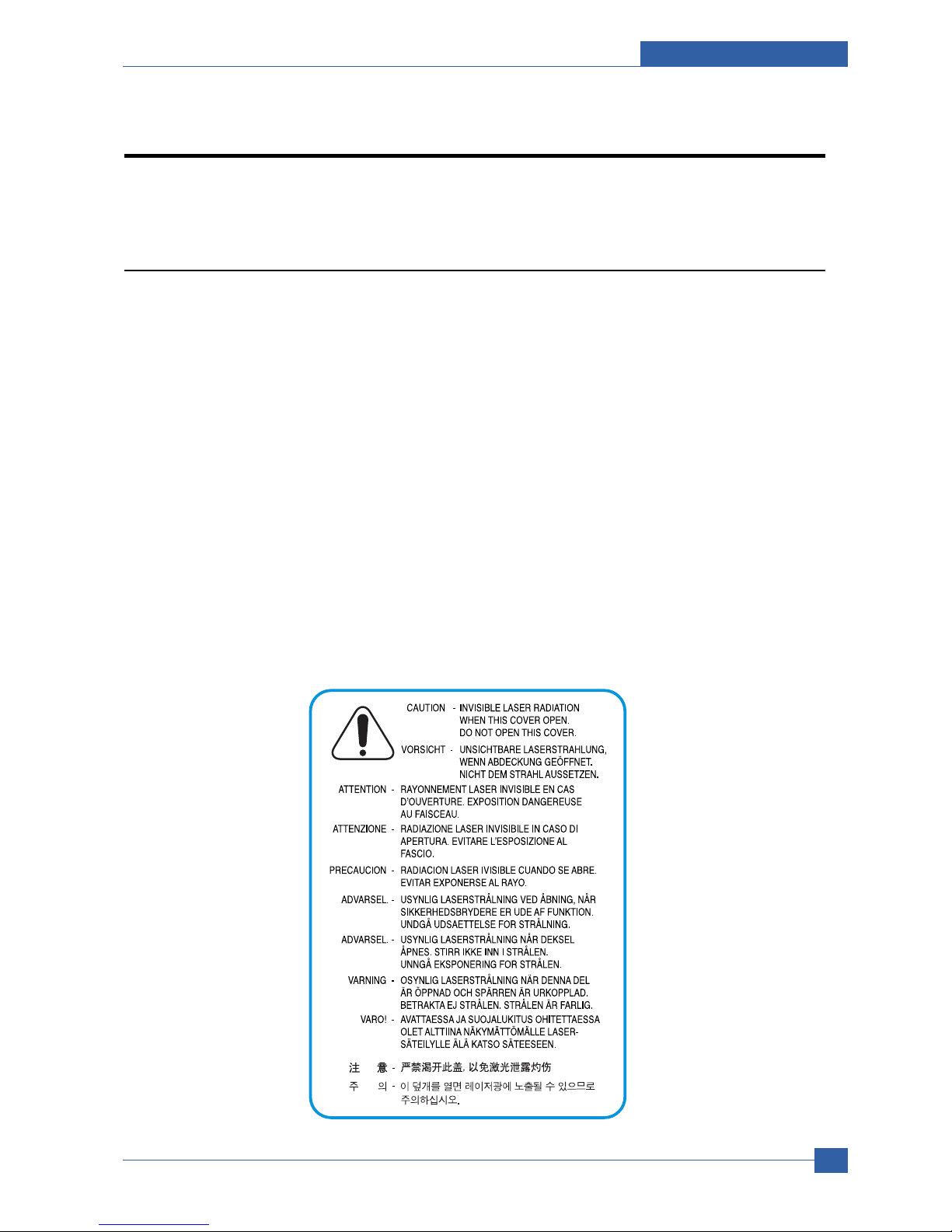
(3) Laser Safety Statement
The Printer is certified in the U.S. to conform to the requirements of DHHS 21 CFR, chapter 1 Subchapter J
for Class 1(1) laser products, and elsewhere, is certified as a Class I laser product conforming to the
requirements of IEC 825.
Class I laser products are not considered to be hazardous. The laser system and printer are designed so
there is never any human access to laser radiation above a Class I level during normal operation, user
maintenance, or prescribed service condition.
Warning >> Never operate or service the printer with the protective cover removed from Laser/Scanner assembly. The reflected
beam, although invisible, can damage your eyes. When using this product, these basic safety precautions should
always be followed to reduce risk of fire, electric shock, and injury to persons.

Samsung Electronics
Service Manual
Precautions
1-2
1.2 Caution for safety
1.2.1 Noxious Material Precaution
The toner in a printer cartridge contains a chemical material, which may harm human body if it is swallowed.
Please keep children out of reach of the toner cartridge.
1.2.2 Electric Shock or fire Precaution
It is possible to get electric shock or burn by fire if you don't fallow the instructions of the manual.
(1) Use exact voltage. Please use an exact voltage and wall socket. If not, a fire or an electric leakage can be
caused.
(2) Use authorized power cord. Do use the power cord supplied with PRINTER. A fire can happen when over cur-
rent flows in the power cord.
(3) Do not insert many cords in an outlet. A fire can be occurred due to flow over current in an outlet.
(4) Do not put water or extraneous matter in the PRINTER. Please do not put water, other liquid, pin, clip, etc. It
can cause a fire, electric shock, or malfunction. If this occurs, turn off the power and remove the power plug
from outlet immediately.
(5) Do not touch the power plug with wet hand. When servicing, remove the power plug from outlet. Do not insert
or take off it with wet hand. Electric shock can be occurr.
(6) Caution when inserting or taking off the power plug. The power plug has to be inserted completely. If not, a fire
can be caused due to poor contact. When taking off the power plug, grip the plug and take it off. If grip the line
and pull over, it could be damaged. A fire or electric shock could happen.
(7) Management of power cord. Do not bend, twist, or bind it and place other materials on it. Do not fix with sta-
ples. If the power cord gets damaged, a fire or electric shock can happen. A damaged power cord must be
replaced immediately. Do not repair the damaged part and reuse it. A repaired part with plastic tape can be
cause a fire or electric shock. Do not spread chemicals on the power cord. Do not spread insecticide on the
power cord. A fire or electric shock can be happen due to thinner(weak) cover of the power cord.
(8) Check whether the power outlet and the power plug are damaged, pressed, chopped, or blazing fire or not.
When such inferiorities are found, repair it immediately. Do not make it pressed or chopped when moving the
machine.
(9) Caution when there is thundering or lightning, and being flash of lightening. It causes a fire or electric shock.
Take the power plug off there is thunder. Do not touch cable and device when thundering and flash of lighten-
ing.
(10) Avoid the place where is moisture or has dust. Do not install the printer where lots of dust or around humidifi-
er. A fire can occurred. A plug part need to clean well with dried fabric to remove dust. If water drops are
dripped on the place covered with dust, a fire can occurred.
(11) Avoid direct sunlight. Do not install the printer near window where direct contacts to the sunlight. If the
machine contacts sunlight long time, the machine cannot work properly because inner temperature of the
machine is getting hotter. A fire can occur.
(12) Turn off the power and take off the plug when smoke, strange smell, or sound from the machine. If you keep
using it, a fire can be occurred.
(13) Do not insert steel or metal piece inside/outside of the machine. Do not put steel or metal piece into a ventila-
tor. An electric shock could happened.

Precautions
Samsung Electronics
Service Manual
1-3
1.2.3 Handling Precautions
If you ignore this information, you could harm machine and could be damaged.
(1) Do not install it on different levels, or slanted floor.
Please confirm whether it is balanced or not after installation. If it is unbalanced, an accident can be hap-
pened due to the machine falling over.
(2) Be careful not to insert a finger or hair in the rotating unit.
Be careful not to insert a finger of hair in the rotating unit (motor, fan, paper feeding part, etc) while the
machine is operating. Once it happens, you could be harmed.
(3) Do not place a pot containing water/chemical or small metals. If they got caught into the inner side of
machine, a fire or electric shock can be occurred.
(4) Do not install it where lots of moisture or dust exists or where raindrop reaches. A fire or electric shock
can be caused.
(5) Do not place a candlelight, burning cigarette, and etc. on the machine. Do not install it near to heater. A
fire can be occurred.
1.2.4 Assembly/Disassembly precaution
When replacing parts, do it very carefully. Memorize the location of each cable before replace parts for reconnecting it afterwards. Do memorize. Please perform the steps below before replace or disassembly the parts.
(1) Check the contents stored in the memory. All the information will be erased after replacing main board.
The information needed to keep has to be written down.
(2) Before servicing or replacing electric parts, take off a plug.
(3) Take off printer cables and power cord connected to printer.
(4) Do use formal parts and same standardized goods when replacing parts.Must check the product name,
part cord, rated voltage, rated current, operating temperature, etc.
(5) Do not give an over-force when release or tighten up the plastic parts.
(6) Be careful not to drop the small parts such as screws in the printer.
(7) Be careful not to change the location of small parts such as screws when assembling and disassembling.
(8) Do remove dust or foreign matters completely to prevent fire of tracking, short, or etc.
(9) After finished repair, check the assembling state whether it is same as before the repair or not.

Samsung Electronics
Service Manual
Precautions
1-4
1.3 ESD Precautions
Certain semiconductor devices can be easily damaged by static electricity. Such components are commonly called
“Electrostatically Sensitive (ES) Devices”, or ESDs. Examples of typical ESDs are: integrated circuits, some field
effect transistors, and semiconductor “chip” components.
The techniques outlined below should be followed to help reduce the incidence of component damage caused by
static electricity.
Caution >>Be sure no power is applied to the chassis or circuit, and observe all other safety precautions.
1. Immediately before handling a semiconductor component or semiconductor-equipped assembly, drain off any
electrostatic charge on your body by touching a known earth ground. Alternatively, employ a commercially available wrist strap device, which should be removed for your personal safety reasons prior to applying power to the
unit under test.
2. After removing an electrical assembly equipped with ESDs, place the assembly on a conductive surface, such
as aluminum or copper foil, or conductive foam, to prevent electrostatic charge buildup in the vicinity of the
assembly.
3. Use only a grounded tip soldering iron to solder or desolder ESDs.
4. Use only an “anti-static” solder removal device. Some solder removal devices not classified as “anti-static” can
generate electrical charges sufficient to damage ESDs.
5. Do not use Freon-propelled chemicals. When sprayed, these can generate electrical charges sufficient to dam-
age ESDs.
6. Do not remove a replacement ESD from its protective packaging until immediately before installing it. Most
replacement ESDs are packaged with all leads shorted together by conductive foam, aluminum foil, or a comparable conductive material.
7. Immediately before removing the protective shorting material from the leads of a replacement ESD, touch the
protective material to the chassis or circuit assembly into which the device will be installed.
8. Maintain continuous electrical contact between the ESD and the assembly into which it will be installed, until
completely plugged or soldered into the circuit.
9. Minimize bodily motions when handling unpackaged replacement ESDs. Normal motions, such as the brushing
together of clothing fabric and lifting one’s foot from a carpeted floor, can generate static electricity sufficient to
damage an ESD.
Product specification and feature
Service Manual
2-1
Samsung Electronics
2
2
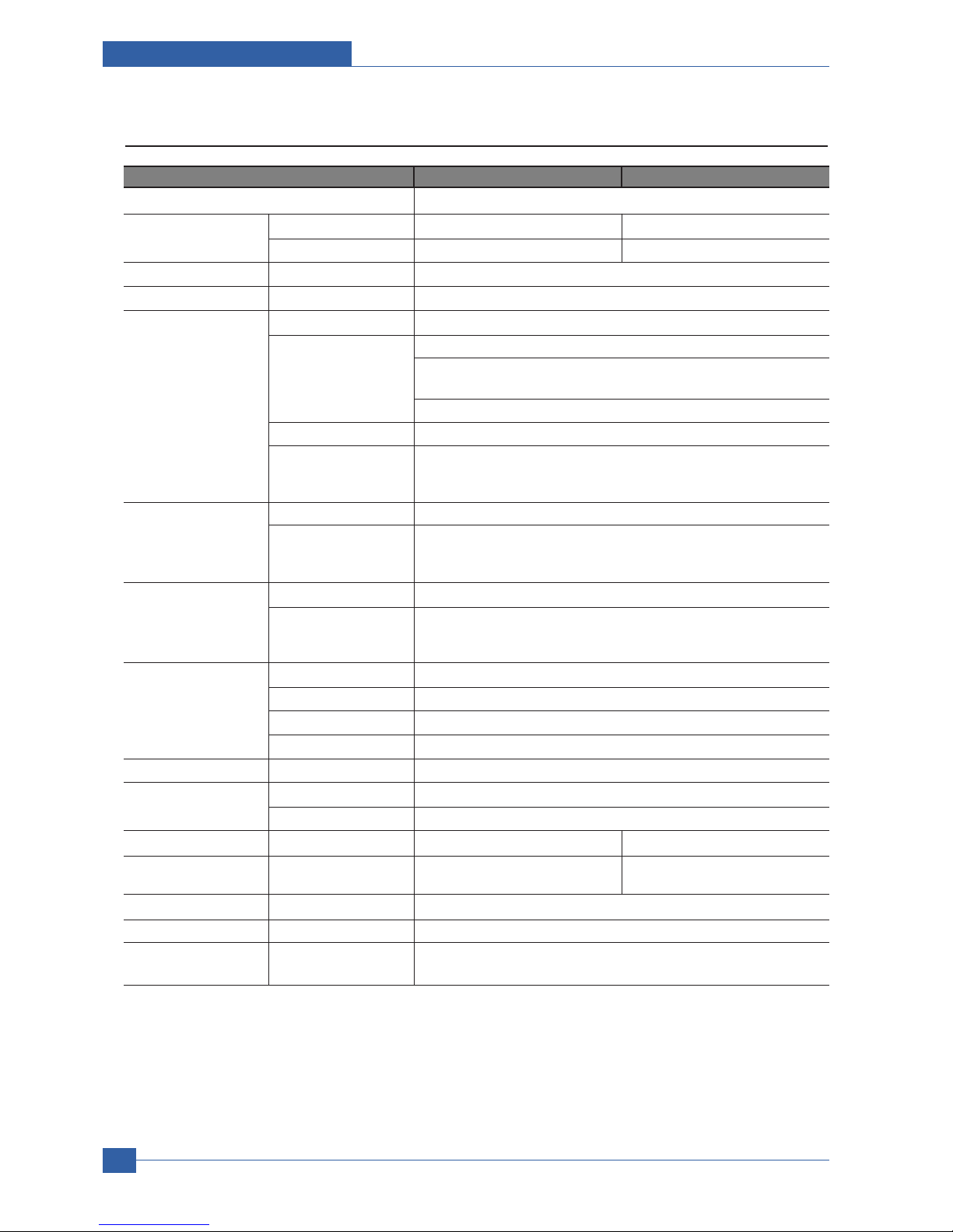
2.1.2 Specifications
Product Specifications are subject to change without notice. See below for product specifications.
2.1.2.1 General Print Engine
ML-347x Series ML-3470D ML-3471ND
Engine Speed Simplex Up to 33 ppm in A4 (35 ppm in Letter)
Duplex Up to 17 ipm in A4 (17.5 ipm in Letter)
Warmup time From Sleep Less than 15 sec, Cold warm-Up time : 15sec
FPOT From Ready Less than 8.5 sec
From Idle Less than 23.5 sec
From Coldboot Less than 30 sec
Resolution - Up to 1,200 x 1,200 dpi effective output
2. Product specification and feature
2.1 Product Specifications
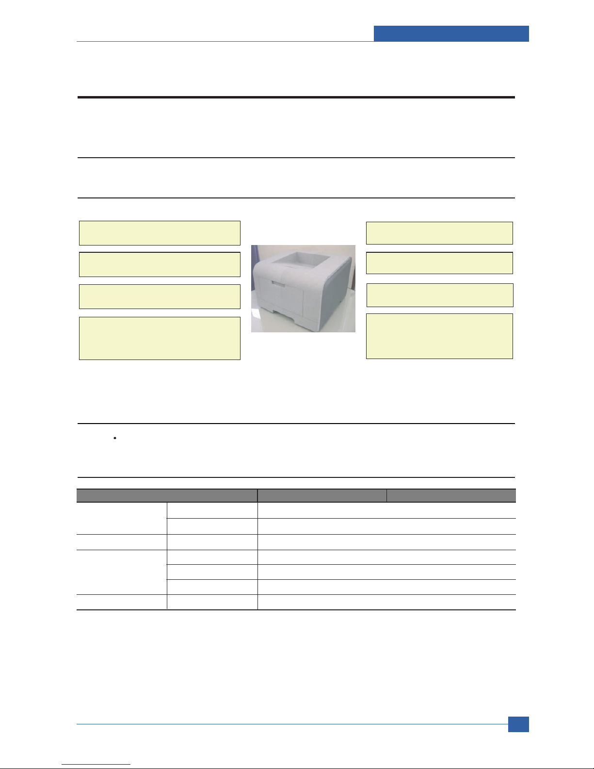
2.1.1 Product Overview
Up to 33ppm (Ltr. 35ppm)
- 250 sheet Cassette
- 50 sheet MP
- 250 sheet Opt. SCF
USB 2.0, IEEE1284
10K Toner (4K Standard)
PCL6, PS3, 1200x1200dpi
400 MHz, 64MB Standard
ML-3471ND
- 10/100 Base TX
- Opt. 802.11b/g Wireless N/W
Built in Duplex
Service Manual
Product specification and feature
2-2
Samsung Electronics
2.1.2.2 Controller & S/W
ML-347x Series ML-3470D ML-3471ND
Processor Samsung 400 MHz
Memory Std. 32 MB 64 MB
Max. 288 MB 320 MB
Printer Languages - PostScript3, PCL6, SPL, IBM ProPrinter, EPSON
Fonts - 45 scalable, 1 bitmap, 136 PostScript3 fonts
Driver Default Driver SPL
Supporting OS Windows 2000/XP/2003/Vista
Various Linux OS including Red Hat, Caldera, Debian, Mandrake, Slackware,
SuSE and Turbo Linux
Mac OS 8.6~9.2/10.1~10.4
WHQL Windows XP/2000/2003
Compatibility PCL6: Win95/98/NT4.0/2000/Me/XP/2003
PS3: Win9x/NT4.0/2000/Me/XP/2003 PPD, Mac PPD, Linux PPD
KS/KSSM: DOS
Wired Network Protocol External : SPX/IPX, TCP/IP, SNMP, HTTP 1.1
Supporting OS Microsoft Windows 98/ME/2000/XP/2003 Microsoft Windows NT 4.xMac OS
8.6 and aboverVarious Linux OS including Red Hat, Caldera, Debian,
Mandrake, Slackware, SuSE and Turbo LinuxNovell 4.x,5.x,6.x
Wireless Network Protocol External : SPX/IPX, TCP/IP, SNMP, HTTP 1.1
Supporting OS Microsoft Windows 98/ME/2000/XP/2003 Microsoft Windows NT 4.xMac OS
8.6 and aboverVarious Linux OS including Red Hat, Caldera, Debian,
Mandrake, Slackware, SuSE and Turbo LinuxNovell 4.x,5.x,6.x
Application RCP N/A
Status Monitor N/A
Smart Panel YES (RCP,SM)
Network Management SAS (Samsung Admin Service), SetIP
Interface
Parallel - IEEE 1284
USB - USB 2.0
Wired Network - N/A Ethernet 10/100 Base TX (Internal)
Wireless Network - N/A Optional (Internal) 802.11b/g
Wireless LAN (Internal)
User Interface
LCD - 2 x 16 Character without backlit
Key - 8 Key: Stop, Toner Save, Duplex
< , OK, >, Menu, Back
Product specification and feature
Service Manual
2-3
Samsung Electronics
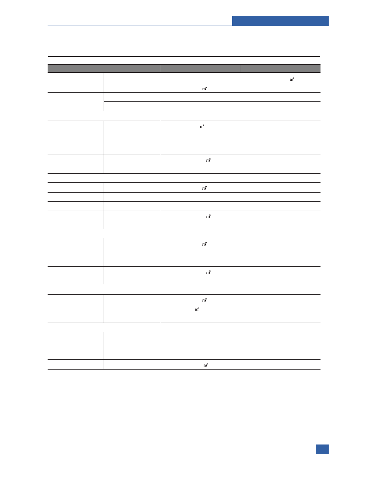
2.1.2.3 Paper Handling
ML-347x Series ML-3470D ML-3471ND
Standard Capacity - 250-sheet Cassette Tray, 50-sheet Multi Purpose Tray @ 75g/
Max. Capacity - 550 sheets @ 75g/
Printing Max. Size 216 x 356 mm (8.5" x 14")
Min. Size 76 x 127 mm (3.0" x 5.0")
Multi-purpose tray
Capacity - 50 sheets @ 75g/
(20lb bond)
Media sizes - A4, A5, A6, Letter, Legal, Folio, Oficio, Executive,ISO B5, JIS B5,
3"x5",Monarch, No.10, DL, C5, C6
Media type - Plain Paper, Transparency, Envelope, Labels, Post Card, Card stock
Media weight - 16~43lb (60 to 163g/ )
Sensing - Paper empty sensor
Standard Cassette Tray
Capacity - 250 sheets @ 75g/
Media sizes - A4, A5, Letter, Legal, Executive, Folio, Oficio, ISO B5, JIS B5
Media types - Plain paper, Thick, Thin, Recycled, Archive
Media weight - 16~28lb (60 to 105g/
)
Sensing - Paper empty sensor
Optional Cassette Tray
Capacity - 250 sheets @ 75g/
Media sizes - A4, A5, Letter, Legal, Executive, Folio, Oficio, ISO B5, JIS B5
Media types - Plain paper, Thick, Thin, Recycled, Archive
Media weight - 16~28lb (60 to 105g/
)
Sensing - Paper empty sensor
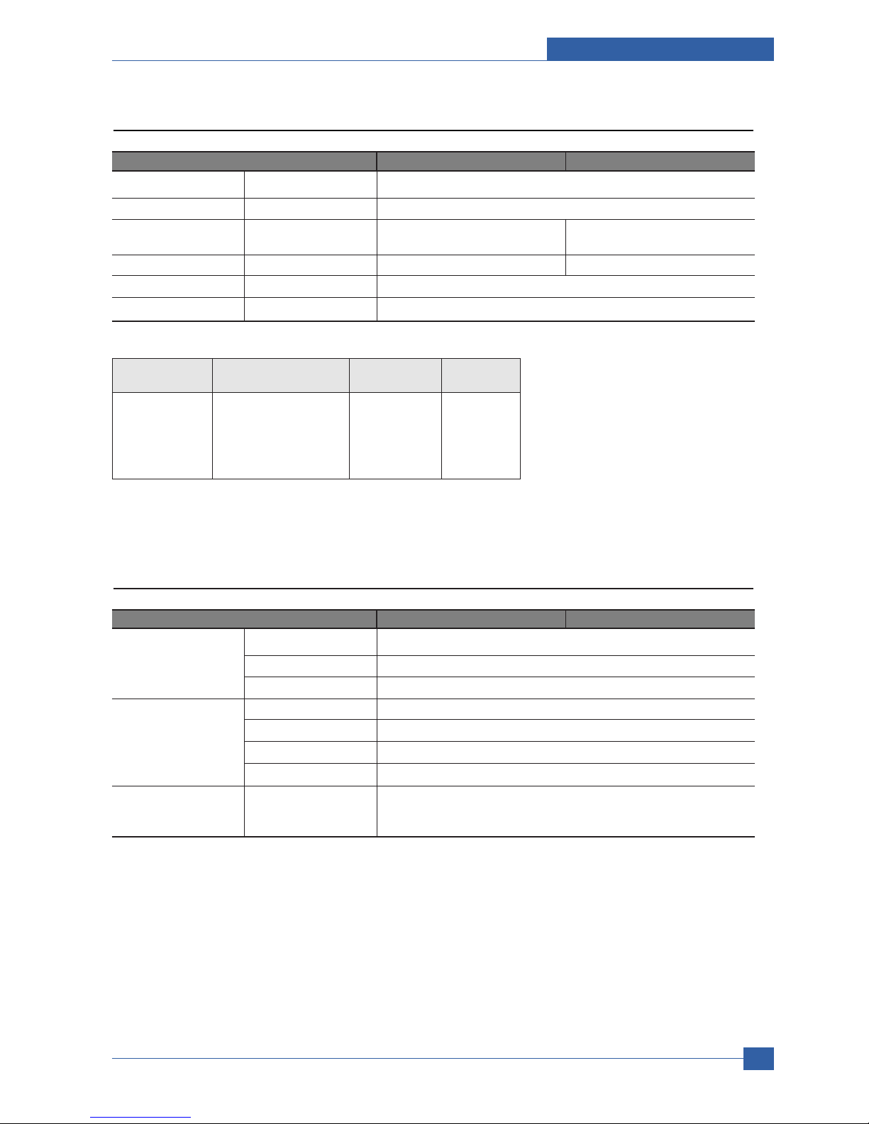
Output Stacking
Capacity Face-Down 150 sheets @ 75g/
Face-Up 1 sheet @ 75g/
Output Full sensing - N/A
Duplex
Supporting - Built-in
Media sizes - A4, Letter, Legal, Folio, Oficio
Media types - Plain Paper
Media weight - 20~24lb (75 to 90g/ )

Service Manual
Product specification and feature
2-4
Samsung Electronics
2.1.2.4 Consumables
ML-347x Series ML-3470D ML-3471ND
Toner Black 4,000 pages @ ISO 19752 Coverage(Standard 4,000 pages, High Yield
10,000 pages)
Key Electronic key(CRUM) Only
Life detect Toner gauge sensor by dot count
Drum Yield 12,000 Images
2.1.2.5 Reliability & Service
ML-347x Series ML-3470D ML-3471ND
Printing Volume - 9,200 sheets-per year / 767 sheets-per month / 38 sheets-per day
(SET AMPV)
5.2 Max. Monthly Duty - 35,000 sheets
5.3 MPBF - 100,000 sheets
5.4 MTTR - 30 min.
5.5 SET Life Cycle - 250,000 sheets or 5 years (whichever comes first)
5.6 RDS Comm. Mode Yes
Operation Yes
2.1.2.6 Environment
ML-347x Series ML-3470D ML-3471ND
Acoustic Noise Level Printing Less than 52.0 dBA
(Sound Power/Pressure)
Standby Less than 26.0 dBA
Sleep Back Ground Level
Power Consumption Ready Less than 130W
AVG. Less than 400W
Max/Peak Less than 700W
Sleep/Power Off Less than 11W / Less than 0.4W
Dimension(W x D x H) SET 400 x 433.4 x 285 mm
Weight SET 10.5 kg (23.15 Pounds)
Gross 14.5kg (31.9 Pounds)
Product specification and feature
Service Manual
2-5
Samsung Electronics
2.1.2.7 Options
ML-347x Series ML-3470D ML-3471ND
*Memory - 16 MB, 32 MB, 64 MB, 128 MB, 256MB
Second Cassette - 250-sheet Cassette Tray
Wired Network - N/A Ethernet 10/100 Base TX
(External) - ML-00ND
Wireless Network - N/A 802.11b/g Wireless LAN (Internal)
Hard Disk - N/A
Duplex Unit - Default
2.1.2.8 Others
ML-347x Series ML-3470D ML-3471ND
Memory Upgradable Mem. Slot 1 EA
Upgradable Mem. Type 100 Pin SDRAM DIMM
Upgradable Mem. Unit 16MB, 32MB, 64MB, 128MB, 256MB
Sensor Paper Empty YES
Paper Size NO
Media Type NO
Paper Full NO
Service Service Item & Period 1. Transfer Roller : 70K pages
2. Fuser Unit : 80K pages
3. Pick-up Roller : 150K pages
* Memory : The ML-3470D or ML-3471ND has 64MB of memory which can be expanded to 320MB.
* Use only the samsung-approved DIMM.
Item Description Model Code Size
(order)
Memory DIMM Exlends your Printers ML-00MA 16MB
memory capacity. ML-00MB 32MB
ML-00MC 64MB
ML-00MD 128MB
ML-MEM140 256MB

Service Manual
Product specification and feature
2-6
Samsung Electronics
2.1.3 Model Comparison Table
Image
Engine SEC SEC SEC SEC
Speed(ppm) 24ppm 28ppm 33ppm 33ppm
Processor 266MHz 400MHz 400MHz 400MHz
Resolution 1,200X1,200 dpi 1,200X1,200 dpi 1,200X1,200 dpi 1,200X1,200 dpi
FPOT 12 sec 8.5 sec 8.5 sec 10 sec
Emulation PS3, PCL6 PCL6 PS3, PCL6 PS3, PCL6
Ram(Std.) 32MB(Max. 160MB) 16MB(Max. 272MB) 64MB(Max. 320MB) 32MB(Max. 288MB)
Interface IEEE1284, USB 2.0 IEEE1284, USB 2.0 IEEE1284, USB 2.0 IEEE1284, USB 2.0
Duplex Yes Factory Option Yes Option
Paper Input 550 Cassette, 100 MP 250 Cassette, 50 MP 250 Cassette, 50 MP 500 Cassette, 100 MP
(Capa./Type) 250 SCF Opt. 250 SCF Opt. 500 SCF Option
Os Compatibility
Win 95/98/NT/2000/ Win 95/98/NT/2000/ Win 2000/ Win 95/98/NT/2000/
Me/XP, Mac Me/XP, Linux Me/XP, Linux Me/XP, Linux
Toner 10K 4K/8K 4K/10K 6K/12 K
SEC SEC SEC SAMSUNG
ML-2550 ML-3050 ML-3471ND ML-3560
2.1.4 Accessory List
JC99-02059A [INA-ACCESSORY]
3903-000085 [CBF-POWER CORD]
6801-00761C [CARD-WARRANTY]
6902-000809 [BAG PE]
JC46-00293A [S/W APPLICATION-CD]
JC46-00354A [S/W APPLICATION-CD]
JC68-00761B [MANUAL-REGISTRATION_FROM]
JC68-01579A [MANUAL-NETWORK GUIDE]
JC68-01584A [LABEL(P)-BLANK 90*25]
JC68-00690A [MANUAL-(CARD)WARRANTY CARD]
JC68-00761D [MANUAL-REGISTRATION]
JC68-01344A [MANUAL-WARRANTY CARD]
JC68-01563A [MANUAL-800 SEC CARD]
Service Manual
Samsung Electronics
2.2 System Overview
2.2.1 System Construction
2.2.1.1 SUMMARY
ML-347x Series is consisted of the Engine parts and F/W, and said engine parts is consisted of the mechanical parts
comprising Frame, Feeding, Developing, Driving, Transferring, Fusing, Cabinet and H/W comprising the main control
board, power board, operation panel, PC Interface.
In ML-347x Series, the main controller is consisted of Asic(SPGPv3) parts, Memory parts, Engine Interface parts and it
functions as Bus Control, I/O Handling, drivers & PC Interface by CPU.
Memory Access supports 16bit Operation, and Program Memory 32MB and Working Memory as well.
In ML-347x Series, the paper path is consisted of 250 sheets Cassette containing friction Pad, pickup-roller,
feed-roller for functioning as registration, Earth-transfer for guiding the transfer inlet, Guide-Tr for guiding sheets
between transferring and fixing, Fuser, Exit Assy.
In ML-347x Series, the driving device is consisted of f55 BLDC motor, OPC, Pick-up, Feed, Gear-Train connected with
Mounting member. - to be changed
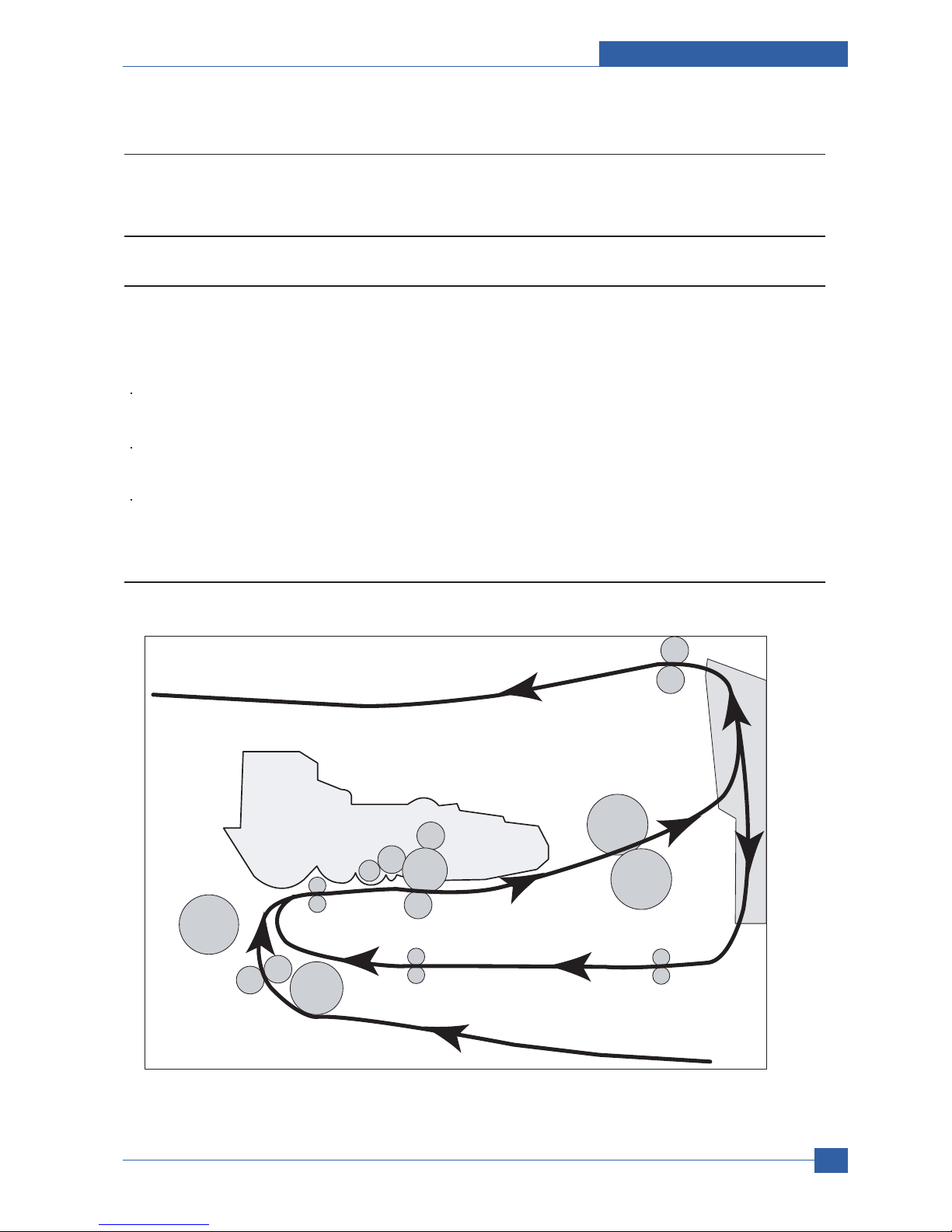
2.2.1.2 System Layout
Roller-Heat
Roller-Exit
Roller-Transfer
Roller-Pickup
Roller-Feed
Roller-MP
Roller-Pressure
Roller-REGI
OPC
Duplex
Duplex
Roller-REGI
OPC
Product specification and feature
Service Manual
2-7
Samsung Electronics
Service Manual
Product specification and feature
2-8
Samsung Electronics
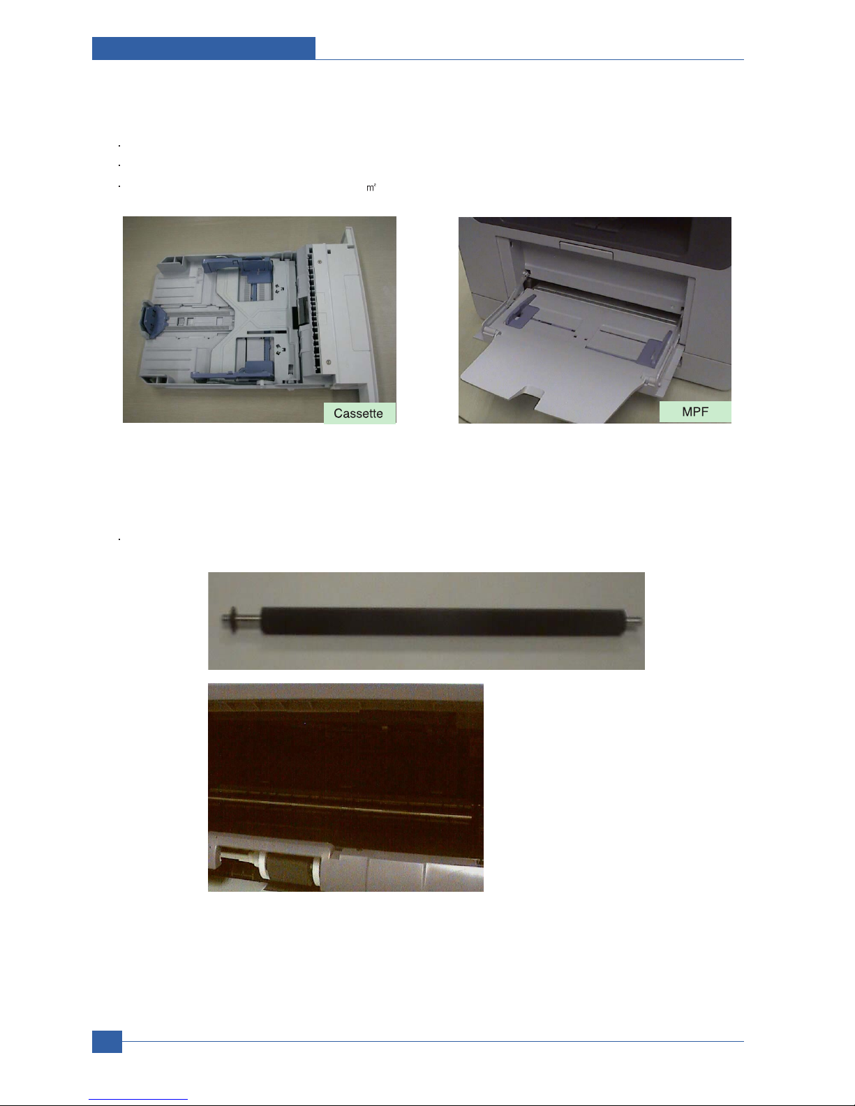
2.2.1.2(a) Feeding Section
Feeding Method : Universal Cassette Type
Feeding Standard : Center Loading
Feeding Capacity : Cassette 250 Sheets (75g/ , 20lb StandardPaper)
2.2.1.2(b) Transfer Ass’y
In Warranty( Life time) : Within 70,000 sheets printing
Product specification and feature
Service Manual
2-9
Samsung Electronics
2.2.1.2(c) Driver Ass’y
MAIN Motor ass’y is for Cassette,MPF and Toner Cartridge
EXIT Motor ass’y is for fuser,exit roller and the initial duplexing feeding
2.2.1.2(d) Fuser Ass’y
Fusing Type : Lamp Type
Heat Roller : [ 28.3 with 0.1 Crown ]
Pressure Roller Pressure Roller 2 : [electrically conductive]
Thermistor - Temperature Detecting Sensor
Thermostat - Overheat Protection Device
Drive Ass'y
Duplex Drive Ass'y
Connection
PCB
Duplex Motor
Service Manual
Product specification and feature
2-10
Samsung Electronics
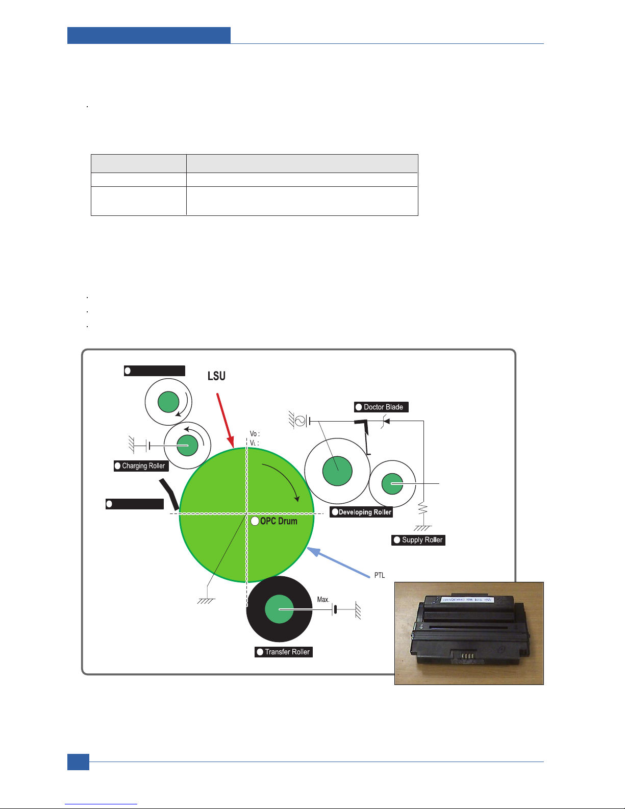
2.2.1.2(f) Toner Cartridge
OPC Cleaning :Mechanical Cleaning by the cleaning blade.
The recycled toner : Trash room for the recycled toner
No shutter for protecting the OPC Drum
2.2.1.2(e) LSU
LSU is consist of LD(Laser Diode) and polygon motor control. When the controller generate the printing signal LD will
turn on and Polygon motor starts.If the receiving part in LSU detect the beam and then Hsync is generated. When the
rotation of poygon motor is steady, it is time of LSU ready status for printing. If either of two condition is not satisfied,
LSU error is expected.
Trouble Failure Analysis
Polygon Motor Error No steady rotation of Polygon Motor
Hsync Error In spite of steady rotation of Polygon Motor,
There is no generation of the Hsync signal
Cleaning Roller
Cleaning Blade
-650V
0.16mW
200V
-1.25KV
V
DC
= -460V
V
PP
= 1520V, f = 2.5KHz, Duty(-) = 32%
1
2
3
4
5
6
7
8
+4.2kV
-50V
+
-
Product specification and feature
Service Manual
2-11
Samsung Electronics
2.2.1.2(g) Duplex Unit
Duplex printing function as factory option
Available Paper : Letter, Legal, Folio, Oficio and A4
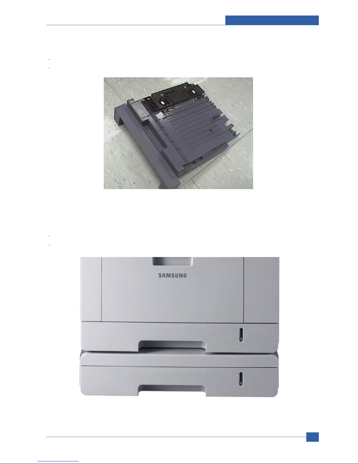
2.21.2(h) Optional Tray (SCF)
For customer covenience in managing paper
Capacity : 250 sheets

Service Manual
Product specification and feature
2-12
Samsung Electronics
2.2.2 Mechanical Parts Specifications
2.2.2.1 Frame
Material : PC + ABS V0 NH-1000T(Cheil Industries)
Weight : 1.0kg
2.2.2.2 Feeding Part
Feeding Type : Universal Cassette Type
Feeding Standard : Center Loading
Feeding Qty : Cassette 250 sheets (75g/ , 20Ib paper standard)
MPF 50 sheets (75g/ , 20Ib paper standard)
Special Media 5 sheets in MPF (OHP, Envelope, Label, Post Card, Index Paper etc.)
Separating Type : Cassette-Friction Pad Type
MPF-Friction Pad Type
Driver Type : Driving by Gearing from Main Motor
Pick Up Roller Driver : Solenoid
Pick Up Roller Rubber Material : EPDM + IR = 1.6 or more
Paper detecting Sensor : Photo Sensor
Paper Size Sensor : None
Paper Separating Pad Material : NBB 52 = 0.8~1.2
Separating Pad Pressure : 190gf
Feeding Pressure (Cassette) : 250 gf 10% (SPRING H mm, based on 1 sheet)
320 gf 10% (SPRING H mm, based on 250 sheet)
Paper Exit Type : Face Down
Feed Roller Driver : Solenoid
2.2.2.3 Transfer Ass’y
It is consisted of PTL(pre-transfer lamp) and Transfer Roller. The PTL sends a light to the OPC drum, makes the current
on the drum surface to low, and improve the transfer efficiency.
The transfer roller delivers the toner of the OPC drum to the paper.
TR Voltage : +1.3KV 5% (based on 200 , in accordance with media area, Transfer table)
-1.20KV 10% (In cleaning)
Transfer Trigger Current : 6.5 5%
Transfer Efficiency : 85% or more (All envirmnment : preferable media)
Voltage System : Voltage PWM Control System
Transfer Roller
- Material : NBR FOAM ROLL
- Structure : Mono layer
- Resistance : 3E +07 ~ 8E +07 (N/N)
- Hardness : 40 3% (ASKER-C)
- Validlength : 224.2 +0.5/-0mm
- OD : 15.0 0.5mm
- SHAFT Material : SUM -24L + Non-electrolysis Ni. Coating
Life Span : Print over 70,000 sheets (in 15~30 )

Product specification and feature
Service Manual
2-13
Samsung Electronics
2.2.2.4 Driver Ass’y
2.2.2.4(a) Motor
Spec : BLDC 62 + PM 55 Motor (2-2 Bipolar) + PM 42 Motor (2-2 Bipolar)
Pull-Out Torque:
BLDC 62 : 1500 gf.cm(based on actual value) or more (1342.4rpm, 1.8A)
PM 55 : 1490gf.cm(based on actual value) or more (711pps, 0.9A)
PM 42 : 240gf.cm(based on actual value) or more (1850pps, 0.6A)
TORQUE MARGIN (Tp/o Tsys) : BLDC 62 Motor : 1500/1100 gf.cm=1.36
PM 55 Motor : 1490/1053 gf.cm = 1.41
PM 42 Motor: 240/165 gf.cm = 1.45
Driving Frequency: BLDC 62 Motor : 1342.4 rpm(1006.8 Clock)
PM 55 Motor : 888.75 rpm(711 pps)
PM 42 Motor : 1156 .25rpm(1850 pps)
It is a power delivery unit by gearing: BLDC 62 Motor -> Pickup/Feeder/Developer
PM 55 Motor -> Fuser/Exit
PM 42 Motor -> Duplex
2.2.2.4(b) Process Speed
Print Speed : 33/35 PPM (based on A4/LTR )
Process Speed : 211.78 mm/sec
Jitter
Vertical : 3 0.018 or less in Vision System
Horizontal : within 2% of partial magnificence error
Orthogonality : SPEC : 1.0 mm or less
2.2.2.4(c) Acoustic Noise
Warming Up : 43dB or less
Printing : 52dB or less
Stand-by : 26dB or less

Service Manual
Product specification and feature
2-14
Samsung Electronics
2.2.2.5 Fixing Part (Fuser)
The fuser is consisted of the E-Coil, Heat Roller, Pressure Roller, Thermistor and Themostat.
It adheres the toner to the paper with pressure and a heat to complete the printing job.
2.2.2.5(a) Halogen Lamp
Voltage 120V : 115 5%
220V : 230 5%
Capacity : 800 Watt 25W
Temp. Distribution : 120%
2.2.2.5(b) Temperature-Interception Device (Thermostat)
Thermostat Type : Non-Contact type THERMOSTAT
Control Temperature : 170 5
THERMOSTAT-ROLLER Gap : 1.6 0.2mm
2.2.2.5(c) Temperature Detecting Sensor(Thermistor)
Thermistor Type : HF-R0060 (SEMITEC 364FL Type)
Temperature Resistance : 7 (180 )
SYSTEM Temperature SETTING
- Stand by : 165 5
- Printing : 189 5 (5 minutes before)
184 5 (5 minutes after)
- Overshoot : 200 less
- Overheat : 210 less
2.2.2.5(d) Heat Roller
Length : 247.5mm
Valid length : 224mm
OD : 28.3 + 0.05, -0.03 (Tubing incl., Crown 0.09~-0.15)
Material : AL(AL5052) + PFA Tubing
Thickness : 0.9mm
Coating Material : PFA 100%
Coating Thickness : 20um (Thickness after abrasion)
GND Type : H/R Bearing Grounding type By SECC Fuser lower frame

Product specification and feature
Service Manual
2-15
Samsung Electronics
2.2.2.5(e) Pressure Roller
Shaft
- Length : 251.3mm
- Material : SUM
- Thickness : 6( 14 - RUBBER portion)
Rubber 1
- Material : Silicon Rubber (Tubing Type : 20)
- Length : 226.4mm
- Thickness : 5mm(one-side)
Rubber 2
- Material : Silicon Rubber (Tubing Type : 16)
- Length : 226.4mm
- Thickness : 5mm(one-side)
OD : 1) 20 0.2(Center part Crown -0.2)
2) 16 0.2(Center part Crown -0.15)
2.2.2.5(f) Media Separating System
PI Coating with PPS Claw System
2.2.2.5(g) Safety Relevant Facts
Proteciong device when overheating
- 1st protecting device : H/W cuts off when detecting an overheating
- 2st protecting device : S/W cuts off when detecting overheating
- 3st protecting device : Thermostat cuts off the power
Safety device
- The power of Fuser is cut-off after front cover is open
- The overheating safety device for customer
- The surface temperature of the Fuser Cover is under 80

2.2.2.7 Toner Cartridge
In the toner cartridge, the OPC unit and the developer unit are in a body.
The OPC unit has OPC drum and charging roller, and the developer unit has toner, toner cartridge, supply roller,
developing roller, and the blade.
2.2.2.7(a) Summary
Developing Method : Non magnetic 1 element contacting method
Toner : Non magnetic 1 element shatter type toner
Charging capacity : -39.1 3 C/g (KAO meas. method)
Average OD : 8.5 0.5 (Toner)
Toner Qty : 125 gf/250gf (4k / 10k)
The life span of toner: 4k/10k sheets (ISO 19752 Pattern / A4 standard )
Toner Residual Sensor : Dot count with CRUM(CRU Monitor)
OPC Cleaning : Collect the toner by using cleaning blade+ FILM OPC
Handling of wasted toner : Collect the wasted toner in the cleaning frame by using cleaning blade
OPC Drum Protecting Shutter : None
Classifying device for toner cartridge: ID is classified by interruption of the frame channel.
2.2.2.7(b) Developing Roller
Roller type : conductive elastic roller
Rotary Speed : 203.06 mm/sec
Roller Bias : -220V ~ -400 20V
Control Type : Bias PWM Control type
Roller material : Conductive NBR + Surface UV process
- Structure : Mono layer
- Resistance : 1.0E+03~ 1.5E+06 (N/N Condition)
- Hardness : 52 5
- Valid Length : 228 mm
- OD : 14.07 mm 0.05
- Shaft material : SUS 303
- Surface roughness (Ra) : Ra 2.0 ~ 2.5 (Circular-direction)
- Friction coefficient (u) : 0.1 ~ 0.5 (70gf, 50mm/min, OHP (3M,#CG3300))
- Life : 10,000 sheets or more
Service Manual
Product specification and feature
2-16
Samsung Electronics
2.2.2.6 LSU (Laser Scanner Unit)
The LSU unit is controlled by video controller. It scans the video data received from video controller with laser beam by
using the rotation principle of the polygon mirror to create the latent image on the OPC drum. It is the core part of LBP.
The OPC drum rotates as the same speed as the paper feeding speed. It creates the /HSYNC signal and sends it to the
engine when the laser beam of the LSU reaches the end of the polygon mirror, and the engine detects the /HSYNC signal
to arrange the vertical line of the image on the paper. After detecting the /HSYNC signal, the image data is sent to the
LSU to arrange the its margin on the paper.
The one side of the polygon mirror is one line for scanning.

Product specification and feature
Service Manual
2-17
Samsung Electronics
2.2.2.7(c) Supply Roller
Rotary Speed : 131.98 mm/sec
Roller Bias : -370V ~ -550V
Control Type : Bias
Roller material : Nylon Fur
- Structure : Closed cell
- Resistance : 0.6E+05 ~ 3.0E+06 (N/N cond.)
- Hardness : 16 ~ 25 (Asker "C")
- Valid Length : 218 mm
- OD : 11.2 0.1 mm
- Shaft material : SUM 24L Non-electrolysis Ni. Coating
- Shaft OD : 8.2 mm + 0 / -0.05
- Driver : Gear Driver (in a direction opposed to D/R)
- Sponge Density : 0.45 , 0.1 g/
- Life : 10,000 sheets or more
2.2.2.7(d) REGULATING BLADE
Type : Regulating toner layer by pressure
Material : SUS 301 1/2H CSP t0.08
Valid Length : 228mm
Voltage : -420V ~ -600V
Regulating edge R value : 0.3 0.02mm
Pressure : 42 gf/cm
2.2.2.7(e) CHARGING PORTION
Type : Conductive Roller Contact-Charge
Rotary Velocity : 179.7 mm/sec
Surface potential : -760 70V (based on OPC , N/N cond.)
Residual potential : -130 V or less (initial)
Control Type : Bias PWM Control
Roller material : Conductive elastic roller (Conductive NBR + SBR)
- Structure : Mono layer (Surface UV process)
- Resistance : 0.75E+06 ~ 5.0E+06 ( N/N cond.)
- Hardness : 50 3 (Asker "A")
- Length : 230 mm
- OD : 12.0 0.05 mm
- Shaft Material : SUM-24L + Non-electrolysis Ni Coating
- Shaft OD : 6 + 0 / -0.05 mm
- Driver : Gear Driver
- Pressure : L:300 gf / R:350 gf
- Roller surface roughness : Ra 1.8 um or less (shaft direction)
- Roller life : 10,000 sheets or more
Roller Voltage : -1.25 ~ -1.70 KV

Service Manual
Product specification and feature
2-18
Samsung Electronics
2.2.3 Engine H/W Specifications
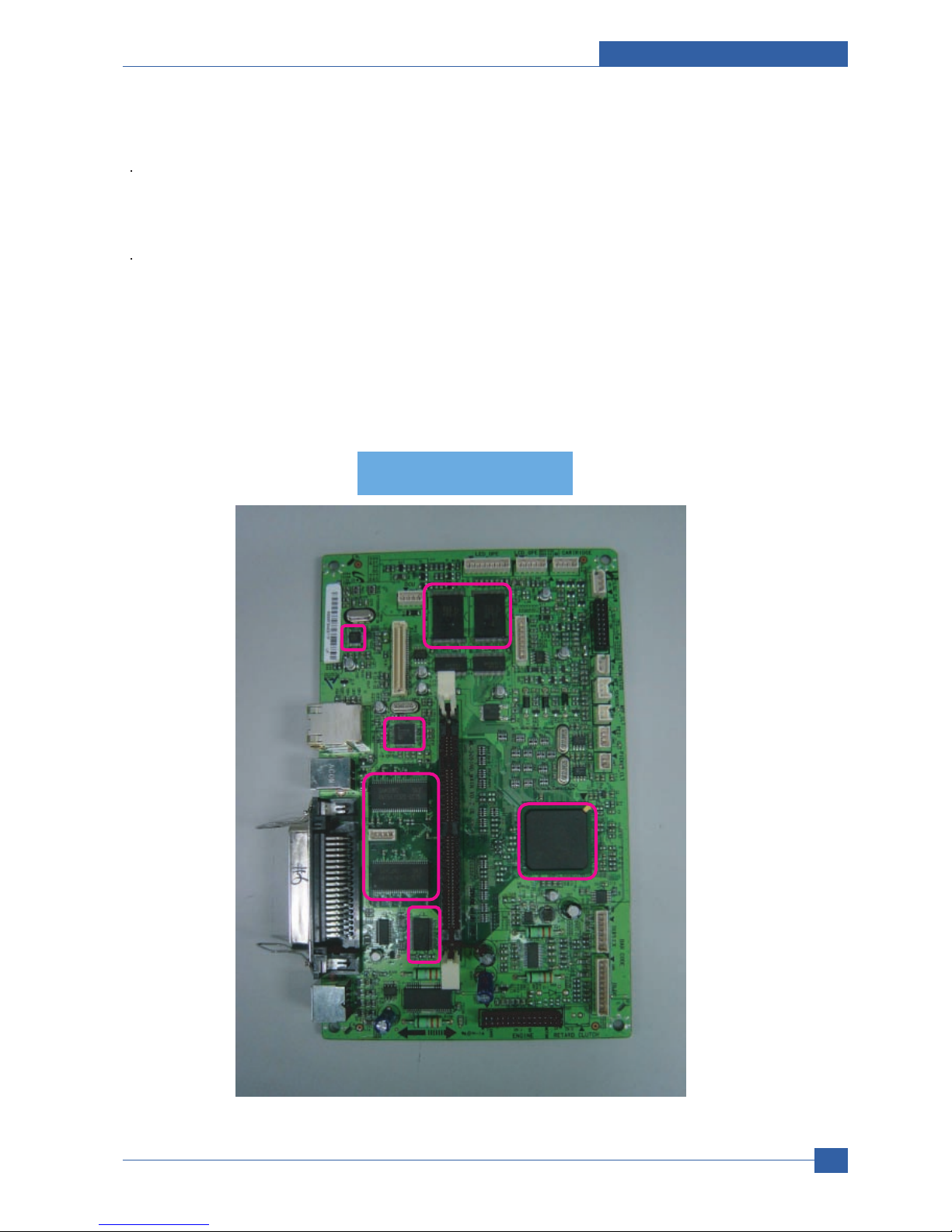
2.2.3.1 ML-347x (PCL) Main Board
The Engine Board and the Controller Board are in one united board, and it is consisted of CPU part and print part in
functional aspect. The CPU is functioned as the bus control, I/O handling, drivers, and PC interface. The main board
sends the Current Image of Video data to the LSU and manages the conduct of Electrophotography for printing. It is
consisted of the circuits of the motor (paper feed, pass) driving, clutch driving, pre-transfer lamp driving, current driving,
and fan driving.
The signals from the paper feed jam sensor and paper empty sensor are directly inputted to the main board.
2.2.3.1(a) Asic(SPGPv3)
CPU Core : ARM1020E
- 32KB instruction cache and 32KB data cache
Operating Frequency
- CPU Core : over 300MHz
- System Bus : 100MHz
SDRAMC
- 32Bits Only, 100MHz
- 5 Banks (Up to 128MB per Bank)
ROMC
- 4 Banks (Up to 16MB per Bank)
IOC
- 6 Banks (Up to 16MB per Bank
DMAC
- 4 Channels
HPVC
- Dual/Single Beam
- LVDS Pad(VDO, HSYNC)
UART
- 5 Channels (1 Channels Supports DMA Operation)
PCI Controller
- 32Bits, 33/66MHz
- PCI Local Bus Specification rev2.2 Complaint
- Host / Agent Mode (Support 4 Devices in Host Mode)
NAND Flash Controller
- 8/16Bits, H/W EEC Generation
- Auto Boot Mode (Using Internal SRAM, 4KB)
MAC
- 10M/100Mbps
- Full IEEE 802.3 Compatibility
Engine Controller
- LSU Interface Unit
- Step Motor : 2 Channels
- PWM : 8 Channels
- ADC : 6 Channels
I2C Controller
- I2C(S-BUS) Slave Device Support(I2C Version 2.1)
RTC
- RTC Core Voltage : 3V
PLL
- 3 PLL : MAIN, PCI, PVC
Product specification and feature
Service Manual
2-19
Samsung Electronics
2.2.3.1(b) Memory
Flash Memory : It stores System Program and downloads the System Program through PC Interface, and in case of
model for export it compresses the PCL font, then stores it.
- Capacity : 32M Byte (NAND Flash)
- Random Access Time : 10 us (Max)
- Serial Page Access Time : 50ns (Min)
DRAM : It is used as Swath Buffer, System Working Memory Area, etc. when printing.
It stores Font List, compressed into Flash memory, on DRAM and uses it as PCL font in case of model for export.
- Capacity : 64M Byte(Basic), up to 320Mbyte (User Option)
- Type : SDRAM 100MHz/133MHz , 16bit
2.2.3.1(c) Others
The Option PBA can be mounted for supporting the serial communication.
Main board
Main board
PHY IC
PHY IC
USB IC
USB IC
SPGPv3
SPGPv3
(ASIC)
(ASIC)
SRAM
SRAM
SDRAM
SDRAM
Flash ROM
Flash ROM

Service Manual
Product specification and feature
2-20
Samsung Electronics
2.2.3.1(d) Flash Memory
It stores the system program and downloads system program through the PC Interface.
Capacity : 16M Byte (NOR Flash)
Access Time : 90ns
Page read Time : 25ns
2.2.3.1(e) SDRAM
It is used as swath buffer, system working memory area, etc. while Printing.
Capacity : The 64M Bytes is for this model (64M : Printing System Working Memory Area)
2.2.3.1(f) Sensor Input Circuit
Paper Empty Sensing
The Paper empty sensor (Photo Interrupter) on the HVPS informs the state of paper to CPU whether it is empty or not
with operation of the actuator.
When cassette is empty, it detects the fact by reading the E20 of CPU, and then informs the fact by displaying the RED.
MP Sensing
By operation of Actuator on the frame, an individual MP Sensor (Photo interrupter) informs the state of paper to CPU
whether it is empty or not. It reads the D17 of CPU for recognizing paper in MP, and paper is fed from MP if there is.
Paper Feeding/With Toner Cartridge Sensing
When paper passes the actuator (feed sensor part), it detects the signal of Photo interrupter, informs the paper feeding
state to CPU, and then sprays the image data after certain time.
If it doesn t detect the feed sensor within 1sec. after paper is fed, paper Jam0 is occurred (LED will be display RED
color). The fact whether the developer is inserted or not is detected by CRUM. After the developer is mounted, the subCRUM can read the information of toner cartridge from contact with CRUM involved in toner cartridge. If the information of
toner cartridge is invalid, it will show invalid sign on a LCD or LED.
Paper Exit Sensing
It detects paper state whether paper gets out from the set with operation of exit sensor on the HVPS and actuator on the
frame. Paper detects the on/off time of exit sensor by reading D22 of CPU, and the normal operation or jam information is
informed to the CPU.
The paper JAM2 is informed. (LED will be display RED color)
Cover Open Sensing
The Cover open sensor is located on the HVPS. After the front cover is opened, +24VS (DC fan, Solenoid, Main Motor,
Polygon motor part of LSU and HVPS), which is supplied to the each unit, is cut off. The cover-open sensing is operated
by the D23 of CPU.
In case, the red will be ON for informing the facts to user.

Product specification and feature
Service Manual
2-21
Samsung Electronics
DC FAN / SOLENOID Driving
It is driven by transistor and controlled by D14(FAN MAIN), E16(FAN DUPLEX), C23(PICK-UP CLUTCH), C18(REGI
CLUTCH), D15(MPF CLUTCH) of CPU.
When it is high, the fan is driving by turning on the TR, and it is off when the sleep mode is selected. There are three
solenoids, and they are driven by paper pick-up, regi and MPF signal. It is turned on or off by C23, C18, D15 of CPU. The
diode protects the driving TR from the noise pulse, which is flown when the solenoid id de-energizing.
FAN Driving Circuit is driven by Transistor, and controlled by D14, E16 of CPU.
Motor Driving
The main motor driving circuits is on the BLDC Motor Ass y Unit. Main Controller has the interfacing circuits. There is
motor driver IC on the motor control board of Motor Ass y Unit.
The exit motor driving circuits is formed when the driver IC is selected. The AN44060A Motor Driver IC is used in this
case. The resistance Rs value for sensing and voltage value for the V reference can be changed by motor driving voltage
value. The motor driving voltage is calculated with the following formula.
The motor driving circuit is formed when the Driver IC is selected. The A3977 Motor Driver IC is used in this case. The
resistance Rs value for sensing and voltage value for the V reference can be changed by motor driving voltage value. The
motor driving voltage is calculated with the following formula.
I = Vref / Rs, wherein Vref is (R1 5V) / (R1+R2).
IN 0, 2 IN 1, 3 Output Current
L L Vref / (10*Rs) = Iout
H L Vref / (15*Rs) = Iout * 2/3
L H Vref / (30*Rs) = Iout * 1/3
HH0

Service Manual
Product specification and feature
2-22
Samsung Electronics
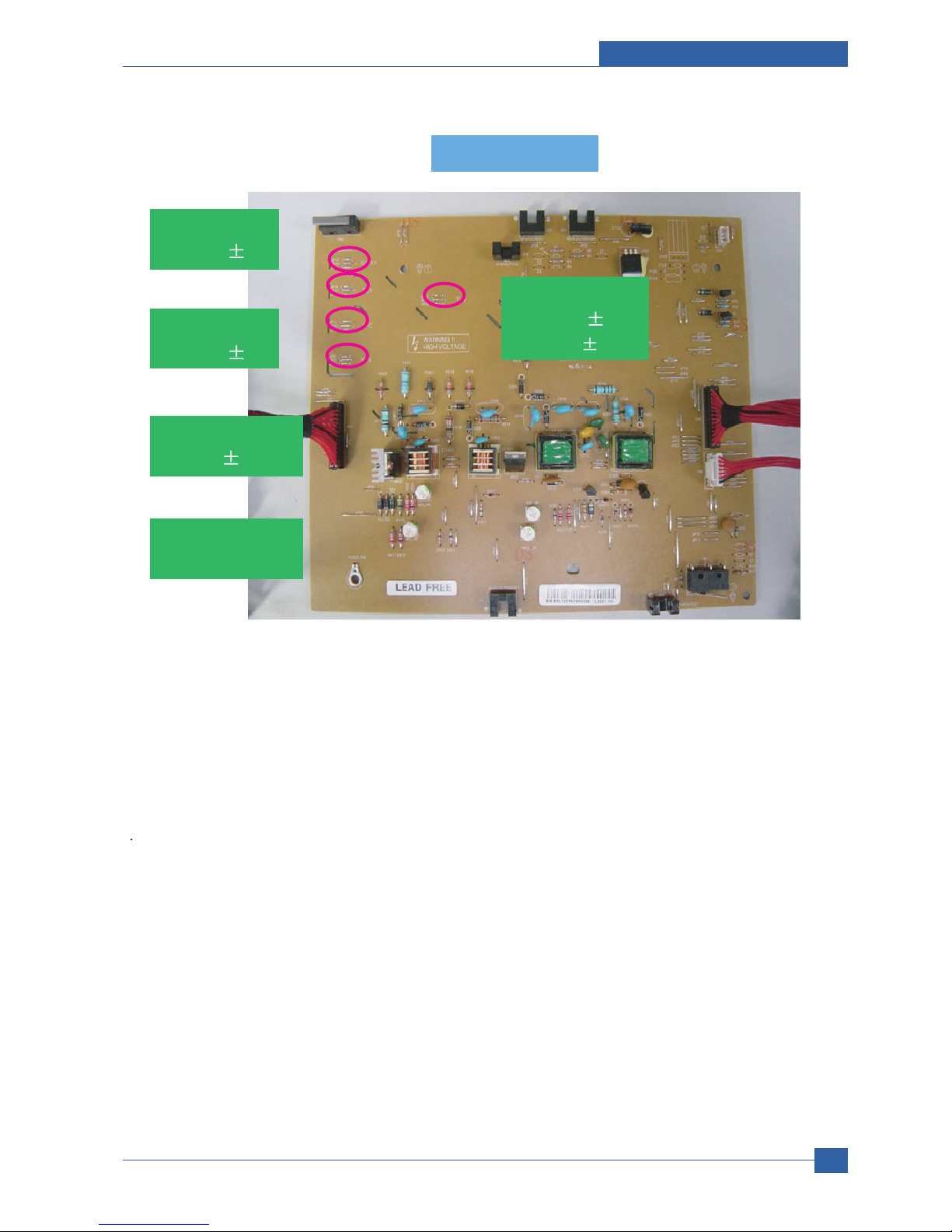
2.2.3.2 SMPS & HVPS board
The SMPS supplies DC Power to the System.
It takes 110V/220V and outputs the +5V, +24V to supply the power to the main board. The HVPS board creates the high
voltage of THV/MHV/Supply/Dev and supplies it to the developer part for making best condition to display the image. The
HVPS part takes the 24V and outputs the high voltage for THV/MHV/BIAS, and the outputted high voltage is supplied to
the toner, OPC cartridge, and transfer roller.
2.2.3.2(a) HVPS (High Voltage Power Supply)
Transfer High Voltage (THV+)
- Input Voltage : 24 V DC 15%
- Output Voltage : MAX +5.0KV 5 %,(Duty Variable, no loading )
->1.2KV 15% (when cleaning,200 )
- Output Voltage Trigger : 6.5
- Input contrast of the Voltage stability degree :under 5 % (fluctuating input 21.6V 26.4V)
Loading contrast : 5 % or less
- Output Voltage Rising Time : 100 ms Max
- Output Voltage Falling Time : 100 ms Max
- Fluctuating transfer voltage with environmental various : +650 V(Duty 10%) ~ 5 KV (Duty 90%)
- Environment Recognition Control Method : The THV-PWM ACTIVE is transfer active signal. It detects the resistance
by recognizing the voltage value, F/B, while permits the environmental recognition voltage.
- Output Voltage Control Method : Transfer Output Voltage is outputted and controlled by changing Duty of THVPWM
Signal. 10% Duty : +650V, 90% Duty : +5KV 5%
Charge Voltage (MHV)
- Input Voltage : 24 V DC 15%
- Output Voltage : -1.3KV ~ -1.8KV DC 50V
- Output Voltage Rising Time : 50 ms Max
- Output Voltage Falling Time : 50 ms Max
- Output Loading range : 30 M ~ 1000 M
- Output Control Signal(MHV-PWM) : CPU is HV output when PWM is Low
Cleaning Voltage (THV-)
- The (+) Transfer Voltage is not outputted because the THV PWM is controlled with high.
- The (-) Transfer Voltage is outputted because the THV-Enable Signal is controlled with low
- The output fluctuation range is big because there is no Feedback control.
Developing Voltage (DEV)
- Input Voltage : 24 V DC 15%
- Output Voltage: -200V ~ -600V DC 20 V
- Output Voltage Fluctuation range: PWM Control
- Input contrast of the output stability degree : 5 % or less
Loading contrast : 5 % or less
- Output Voltage Rising Time : 50 ms Max
- Output Voltage Falling Time : 50 ms Max
- Output Loading range : 10M ~ 1000 M
- Output Control Signal (BIAS-PWM) : the CPU output is HV output when PWM is low.
Supply
- Output Voltage : -400 V ~ -800V DC 50 V(ZENER using, DEV )
- Input contrast of the output stability degree : under 5 %
Loading contrast : 5 % or less
- Output Voltage Rising Time : 50 ms Max
- Output Voltage Falling Time : 50 ms Max
- Output Loading range : 10 M ~ 1000 M
- Output Control Signal (BIAS-PWM) : the CPU is HV output when PWM is low.
Product specification and feature
Service Manual
2-23
Samsung Electronics
2.2.3.2(b) SMPS (Switching Mode Power Supply)
It is the power source of entire system. It is assembled by an independent module, so it is possible to use for common
use. It is mounted at the side of the set.
It is consisted of the SMPS part, which supplies the DC power for driving the system, and the AC heater control part,
which supplies the power to fuser. SMPS has two output channels. Which are +5V and +24V.
AC Input
- Input Rated Voltage : AC 220V ~ 240V AC 110V ~ 127V
- Input Voltage fluctuating range : AC 198V ~ 264V AC 99V ~ 135V
- Rated Frequency : 50/60 Hz
- Frequency Fluctuating range : 47 ~ 63 Hz
- Input Current : Under 4.0Arms / 2.0Arms (But, the status when e-coil is off or rated voltage is inputted/outputted )
HVPS PBA
HVPS PBA
SUPPLY
-630
3%
THV
+1300
3%
-1200
3%
OPC
-130
15.4%
MHV
-1350¡ 3%
DEV
-430
3%

Service Manual
Product specification and feature
2-24
Samsung Electronics
NO ITEM CH1 CH2 Remark
1 CHANNEL NAME +5V +24.0V
2 CONNECTOR PIN CON 35V PIN: 11,13,15 CON 324V PIN:3,5,7,9
GND PIN: 12,14,16 GND PIN:4,6,8,10
3 Rated Output +5V 5%(4.75 5.25V) +24V 10%(21.6 26.4V)
4 Max. Output Current 3 A 4.4 A
5 Peak Loading Current 3.6 A 5.3 A 1ms
6 RIPPLE NOISEVoltage 100mVp-p Under 500mVp-p
7 Maximum output 15W 105.6W
8 Peak output 18W 127.2W 1ms
9 Protection for loading Shut down or Fuse Shut down or Output
shortage and Protection Voltage Drop
overflowing current
NO ITEM System
1 Stand-By Less than 130W
2 PRINTING Less than 400W
3 Sleep-Mode Less than 11W
Fuse 5V
Fuse 5V
Fuse 24V
Fuse 24V
Fuse 5V
Fuse 5V

Product specification and feature
Service Manual
2-25
Samsung Electronics
Length of Power Cord : 1830 50mm
Power Switch : Use
Feature
- Insulating Resistance : 100 or more (at DC 500V)
- Withstanding Voltage : Must be no problem within 1 min.
(at 1000V-LV model / 1500Vac-HV model,10mA)
- Leaking Current : under 3.5mA
- Running Current : under 40A PEAK (AT 25 , COLD START)
under 60A PEAK (In other conditions)
- Rising Time : within 2Sec
- Falling Time : over 20ms
- Surge : Bi-Wave 3kV - Normal, 6KV - Common
Environment Condition
- Operating temperature range : 0 40
- Maintaining temperature range : -25 85
- Preserving Humidity Condition : 30% 90% RH
- Operating atmospheric pressure range : 1atm
EMI Requirement : CISPR ,FCC, CE, MIC, C-Tick,
Safty Requrement :IEC950 UL1950, CSA950, C-UL,NOM, TUV, Semko, Nemko, iK, CB, CCC(CCIB), GOST, EPA,
Power Save
2.2.3.2(c) FUSER AC POWER CONTROL
Fuser(e-coil) gets heat from AC power. The AV power controls the switch with the Triac, a semiconductor switch. The
ON/OFF control is operated when the gate of the Triac is turned on/off by Phototriac (insulting part).
In other words, the AC control part is passive circuit, so it turns the heater on/off with taking signal from engine control
part.
When the HEATER ON signal is turned on at engine, the LED of PC501 (Photo Triac) takes the voltage and flashes.
From the flashing light, the Triac part (light receiving part) takes the voltage, and the voltage is supplied to the gate of
Triac and flows into the Triac. As a result, the AC current flows in the e-coil, and heat is occurred.
On the other hand, when the signal is off, the PC501 is off, the voltage is cut off at the gate of Triac, the Triac becomes
off, and then the e-coil is turned off.
Triac (Q501) feature : 24A-LV model / 16A-HV model, 600V SWITCHING
Phototriac Coupler (PC501)
- Turn On If Current : 15mA 50mA(Design: 16mA)
- High Repetive Peak Off State Voltage : Min 600V

Service Manual
Product specification and feature
2-26
Samsung Electronics
2.2.3.3 Engine F/W
2.2.3.3(a) Control Algorithm
Feeding
If feeding from a cassette, the drive of the pickup roller is controlled by controlling the solenoid. The on/off of the solenoid
is controlled by controlling the general output port or the external output port. While paper moves, occurrence of Jam is
judged as below.
Transfer
The charging voltage, developing voltage and the transfer voltage are controlled by PWM (Pulse Width Modulation). The
each output voltage is changeable due to the PWM duty. The transfer voltage admitted when the paper passes the
transfer roller is decided by environment recognition. The resistance value of the transfer roller is changed due to the
surrounding environment or the environment of the set, and the voltage value, which changes due to the environments, is
changed through AD converter. The voltage value for impressing to the transfer roller is decided by the changed value.
Each voltage value is controlled according to 3.3.3.2 Timing Chart.
Fusing
The temperature change of the heat roller s surface is changed to the resistance value through the thermistor. By
converting the voltage value, which impressed to the resistance, to the digital value through the AD converter, the
temperature is decided. The AC power is controller by comparing the target temperature to the value from the thermistor.
If the value from the thermistor is out of controlling range while controlling the fusing, the error stated in the below table
occurs.
ITEM Description
JAM 0 - After picking up, paper cannot be entered due to paper is not fed.
- After picking up, paper entered but it cannot reach to the feed sensor in certain time due to slip, etc.
- After picking up, if the feed sensor is not on, re-pick up. After re-picking up, if the feed sensor is not on
after certain time, it is JAM 0.
*It is a status that the leading edge of the paper doesn t pass the feed sensor.
-Even though the paper reaches to the feed sensor, the feed sensor doesn t be ON.
*It is a status that the leading edge of the paper already passes the feed sensor.
JAM 1 - After the leading edge of the paper passes the feed sensor, the trailing edge of the paper cannot pass
the feed sensor after a certain time. (The feed sensor cannot be OFF)
- After the leading edge of the paper passes the feed sensor, the paper cannot reach the exit sensor after
certain time. (The exit sensor cannot be ON)
*The paper exists between the feed sensor and the exit sensor.
JAM 2 - After the trailing edge of the paper passes the feed sensor, the paper cannot pass the exit sensor after
certain time.

Product specification and feature
Service Manual
2-27
Samsung Electronics
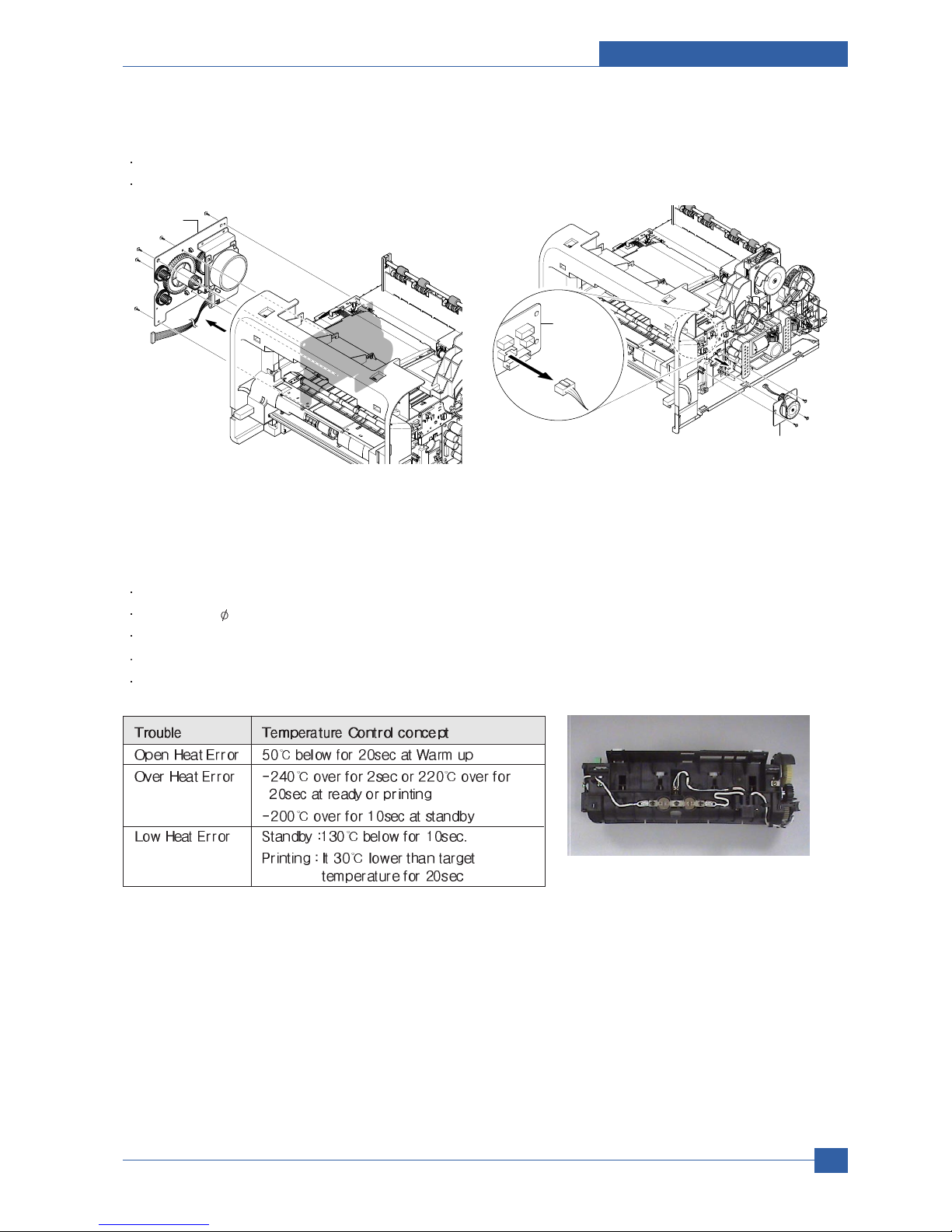
Open Heat Error
When the engine operates the warm-up process, if the temperature of the fixing unit is not higher than a specified
temperature, the engine defines Open Heat Error. When this error is broken out, the engine stops all functions and keeps
the error state. Also, the engine informs the error status of the main system. And then the error message is displayed at
LCD window or LED informing the error status of the user.
Low Heat Error
When the engine is at stand-by, printing or warm-up mode, if the temperature of the fixing unit is lower than the specified
temperature at each state and the lower temperature state is maintained during the specified time, the engine defines
Low Heat Error. When this error is broken out, the engine stops all functions and keeps it at the error state. Also the
engine informs the error status of the main system. And then the error message is displayed at LCD window or LED
informing the error status of the user.
Over Heat Error
For overall engine state, if the temperature of the fixing unit is higher than the specified temperature and the temperature
state is kept during the specified time, the engine defines Over Heat Error. When this error is broken out, the engine stops
all functions and keeps it at the error state. Also, the engine informs the error status of the main system. And then the
error message is displayed at LCD window or LED to inform the error status of the user.
* To recover the heat error: The heat error recovery is operated automatically when the error is only caused by Low Heat
Error, not the Heat Errors in Warm-up state and the Over Heat Error. If an error happens, then the engine memorizes a
present temperature. In case of Low Heat Error, the maximum heat is supplied to the fixing unit. When a specified time
is elapsed, the engine detects the temperature again. If the present temperature is higher than the memorized
temperature, the error is recovered. In case of Over Heat Error, no heat is supplied to the fixing unit. When a specified
time is elapsed, the engine detects a present temperature again. If the present temperature is a specified degree lower
than the memorized temperature, the error is recovered.
LSU
LSU receives the image data from PVC or HPVC and make the latent image on OPC surface.
It uses the dual beam, LD1 and LD2. But the control method of them is the same.
Just in comparison with the single beam, the dual beam has the half of lsu s frequency.
->The frequency of the dual beam = the frequency of the single beam /2.
The errors related to LSU are as follows:
* By LReady: When the printing is started, the engine drives the polygon motor of LSU. After the specified time is elapsed,
if the motor is not in a ready status, the engine detects the error that the polygon motor is not in a ready status. If this
error happens, the engine stops all functions and keeps it at the error state. Also, the engine informs the error status of
the main system and the error message is displayed at LCD window to inform the error status of the user.
* By Hsync: When the polygon motor is ready, the LSU sends out the signal called Hsync and used to synchronize with
each image line. So, if the engine does not detect consecutively the signal for a fixed time, it defines the Hsync Error. If
this error happens, the engine stops all functions and keeps it at the error state. Also, the engine informs the error status
of the main system and then the error message is displayed at LCD window to inform the error status of the user.
LSU Error Recovery: If the LReady or Hsync error happens, the paper exits out beforehand. The engine mode is
changed to recovery mode and the engine informs the main system of the engine mode. And the engine checks the LSU
error. If the error doesn t happen, the printing job will be proceeding.

Service Manual
Product specification and feature
2-28
Samsung Electronics
2.2.4 S/W Descriptions
2.2.4.1 Overview
The software of Cygnus system is constructed with
1) Host Software part that the application software operated in Window and Web Environment, and
2) Firmware parts that is a Embedded software controls printing job.
2.2.4.2 Architecture
Host Software is made up of
1. Graphic User Interface that offers the various editing functions to user in Host,
2. Driver that translates the received document to a Printing Command language which printer can understand and
transfers data to spooler,
3. Stand-alone Application that offers the various printing application, DMS(Document Management System),
RCP(Remote Control Panel), Printer Status Monitor, Network Management in Window system,
4. Web-based-Application that offers the same functions as Stand-alone Application and RDC(Remote Diagnosis
Control) in Web environment.
Firmware is made up of
1. Application (Emulation) that is a interpreter translate data received from Host to a printing language (PCL, PS, GDI,
etc.) to be able to make the user to take same output as originally one what composed in Host.
2. Kernel that control and management the whole procedure include of Control flow and Printing Job before transfer to
Engine system.

Product specification and feature
Service Manual
2-29
Samsung Electronics
2.2.4.3 Data and Control Flow
The above Block Diagram is explained that:
Host Side is made up of
1. Driver that is Windows application software translate printed data to one of printer language and create spooler file,
2. Web-based Application that offer a various printer additional functions, management of printing job, printer
administration, Status monitor to monitoring the printer status by real time in Web, independent environment on OS.
3. Stand-alone Application that is a similar Window software as same as above 2,
4. Port Monitor that manages the network communication between spooler and Network Interface Card, or various
additional application and Network Interface Card,(this is, at first, make communication logical port, manage the data,
transfer them from spooler to network port, and offer the result of printing).

Service Manual
Product specification and feature
2-30
Samsung Electronics
Firmware Side is made up of
1. Network Interface Card is that relay the communication between Host and kernel using various network protocol,
2. Kernel is that manages the flow control of emulation procedure, receiving data from Host or Network card and printing
with engine & rendering job,
3. Emulation is that interprets the various output data from selected emulation,
4. Engine is that prints rendered bit-map data to paper with required size and type by Kernel.
And then, for Job Spooling function for Multi-User, Multi-Printing that is occurred in Network printing and various additional
printing functions, this Kernel use max. 10 Queuing systems in a memory.
In Printing, the two procedures are
(1) Case of using Parallel or USB Port
After user start to print the wanted document to PCL string or compressed GDI bit-map data, Driver translate the all
graphic data of it and send data to host spooler. And then the spooler sends the data stream to the printer via
parallel port or USB port.
Kernel receives this data from Host, and then select emulation fit to data and start selected one. After emulation job
end, Kernel sends the output bit-map data to Engine using Printer Video Controller (by clock type for LSU).
Engine print the received data to required paper with the sequential developing process.
(2) Case of using Network Interface Card
After user start to print the wanted document to PCL string or compressed GDI bit-map data, Driver translate the all
graphic data of it and send data to host spooler.
If so, Port monitor managing network port receives data from spooler and sends a data stream to the Network
Interface Card.
Network interface card receives it and send to Kernel part,
Kernel receives this data from Host, and then select emulation fit to data and start selected one. After emulation job
end, Kernel sends the output bit-map data to Engine using Printer Video Controller (by clock type for LSU).
Engine print the received data to required paper with the sequential developing process.
The additional printing function are realized in
(1) Web environment
(2) Window environment.
On addition, Kernel informs a status of printing status and printer status to user made printing job with the Status Monitor.

Disassembly and Reassembly
Samsung Electronics
Service Manual
3-1
3
3. Disassembly and Reassembly
3.1 General Precautions on Disassembly
When you disassemble and reassemble components, you must use extreme caution. The close proximity of cables
to moving parts makes proper routing a must.
If components are removed, any cables disturbed by the procedure must be restored as close as possible to their
original positions. Before removing any component from the machine, note the cable routing that will be affected.
Whenever servicing the machine, you
must perform as follows:
1. Check to verify that documents are not stored in
memory.
2. Be sure to remove the toner cartridge before you
disassemble parts.
3. Unplug the power cord.
4. Use a flat and clean surface.
5. Replace only with authorized components.
6. Do not force plastic-material components.
7. Make sure all components are in their proper position.
Releasing Plastic Latches
Many of the parts are held in place with plastic latches.
The latches break easily; release them carefully.
To remove such parts, press the hook end of the latch
away from the part to which it is latched.
Samsung Electronics
Service Manual
Disassembly and Reassembly
3-2
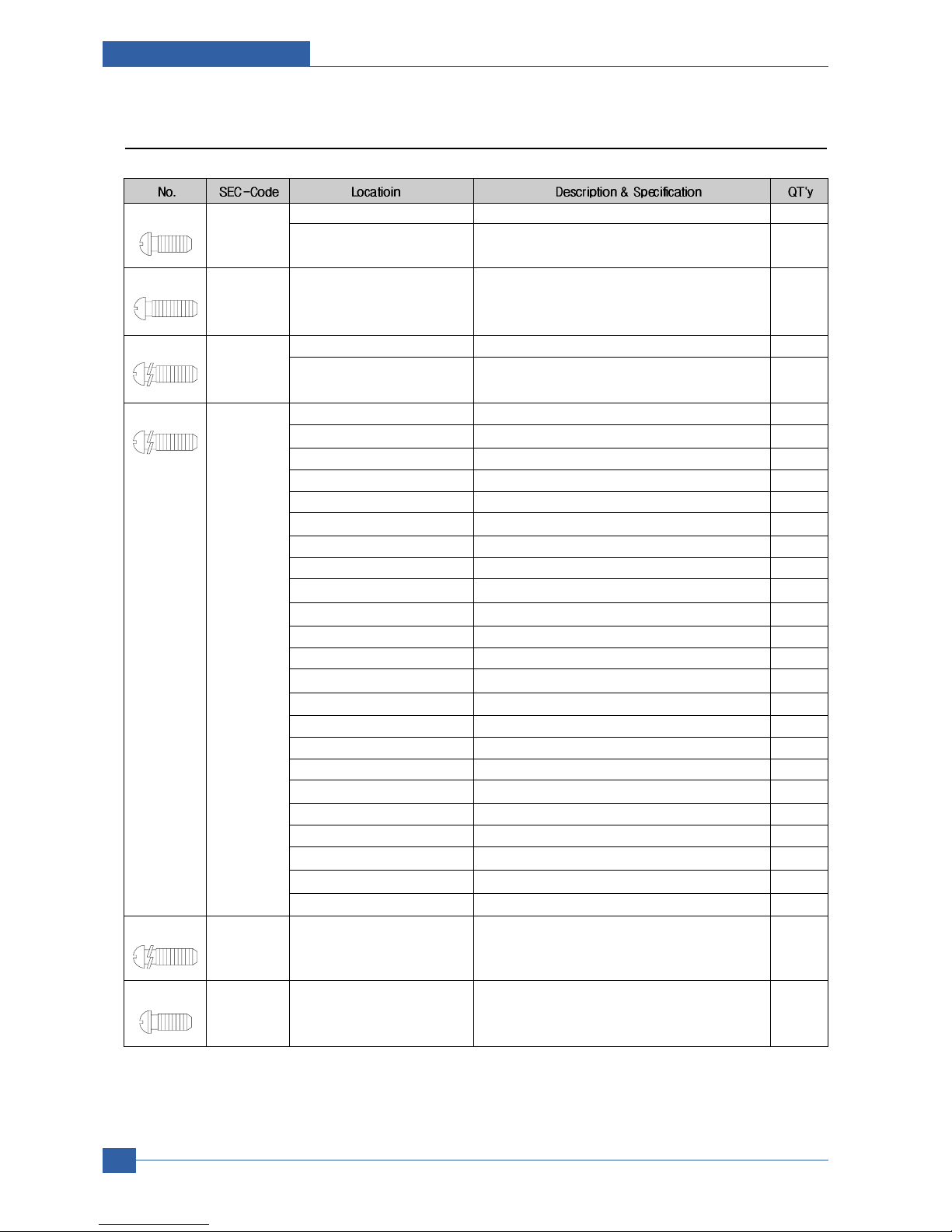
3.2 Screws used in the Printer
S1(BH Short) 6001-000130 SCREW-MACHINE;BH,+,M3,L6,ZPC(WHT),SWRCH18A,-,- 3
SCREW-MACHINE;BH,+,M3,L6,ZPC(WHT),SWRCH18A,-,- 2
S2(PH Long) 6001-000568 SHIELD+PARRALLEL PORT SCREW-MACHINE;PH,+,M3,L8,NI PLT,SWRCH18A,FP,- 2
S3(WH Long) 6002-000440 SCREW-TAPPING;PWH,+,-,2,M3,L8,ZPC(BLK),SWRCH18A,- 4
SCREW-TAPPING;PWH,+,-,2,M3,L8,ZPC(BLK),SWRCH18A,- 1
S4(WH Long) 6003-000196 COVER MIDDLE+FRAME BASE SCREW-TAPTITE;PWH,+,B,M3,L10,NI PLT,SWRCH18A 6
COVER REAR SCREW-TAPTITE;PWH,+,B,M3,L10,NI PLT,SWRCH18A 4
COVER SIDE L SCREW-TAPTITE;PWH,+,B,M3,L10,NI PLT,SWRCH18A 1
COVER SIDE R SCREW-TAPTITE;PWH,+,B,M3,L10,NI PLT,SWRCH18A 1
COVER TOP SCREW-TAPTITE;PWH,+,B,M3,L10,NI PLT,SWRCH18A 4
DUP DRIVE ASS'Y+FRAME BASE SCREW-TAPTITE;PWH,+,B,M3,L10,NI PLT,SWRCH18A 3
DUP FAN+FRAME BASE SCREW-TAPTITE;PWH,+,B,M3,L10,NI PLT,SWRCH18A 1
MAIN DRIVE ASS'Y+FRAME BASE SCREW-TAPTITE;PWH,+,B,M3,L10,NI PLT,SWRCH18A 6
SHIELD CONTROLLER+FRAME BASE SCREW-TAPTITE;PWH,+,B,M3,L10,NI PLT,SWRCH18A 3
SHIELD SMPS+FRAME BASE SCREW-TAPTITE;PWH,+,B,M3,L10,NI PLT,SWRCH18A 3
Frame Base+Fuser SCREW-TAPTITE;PWH,+,B,M3,L10,NI PLT,SWRCH18A 4
frame assy SCREW-TAPTITE;PWH,+,B,M3,L10,NI PLT,SWRCH18A 33
SCREW-TAPTITE;PWH,+,B,M3,L10,NI PLT,SWRCH18A 1
FRAME MP+BRACKET FEED SCREW-TAPTITE;PWH,+,B,M3,L10,NI PLT,SWRCH18A 2
FRAME MP+HOLDER IDLE FEED SCREW-TAPTITE;PWH,+,B,M3,L10,NI PLT,SWRCH18A 2
FRAME MP+SOLENOID SCREW-TAPTITE;PWH,+,B,M3,L10,NI PLT,SWRCH18A 1
SCREW-TAPTITE;PWH,+,B,M3,L10,NI PLT,SWRCH18A 3
Frame Dup+Bracket Align Dup SCREW-TAPTITE;PWH,+,B,M3,L10,NI PLT,SWRCH18A 2
Frame Dup+Guide Upper Dup SCREW-TAPTITE;PWH,+,B,M3,L10,NI PLT,SWRCH18A 4
COVER FRONT+HOLDER LOCKER SCREW-TAPTITE;PWH,+,B,M3,L10,NI PLT,SWRCH18A 2
COVER MIDDLE+CAP SUB ACTUATOR
SCREW-TAPTITE;PWH,+,B,M3,L10,NI PLT,SWRCH18A 1
PBA+COVER KEY MENU_LCD SCREW-TAPTITE;PWH,+,B,M3,L10,NI PLT,SWRCH18A 4
COVER CASSETTE+FRAME CASSETTE
SCREW-TAPTITE;PWH,+,B,M3,L10,NI PLT,SWRCH18A 2
S5(WH Long) 6003-000221 BLDC MOTOR+BRKT MOTOR SCREW-TAPTITE;PWH,+,-,S,M4,L8,ZPC(WHT),SWRCH18A,- 4
S6(BH Short) 6003-000261 PLATE KNOCKUP+CAM KNOCKUP SCREW-TAPTITE;BH,+,-,B,M3,L6,ZPC(WHT),SWRCH18A,- 1

Disassembly and Reassembly
Samsung Electronics
Service Manual
3-3
S7(WH Short) 6003-000264
TRAYASF INPUT UPPER+GEAR PINION
SCREW-TAPTITE;PWH,+,-,B,M3,L6,ZPC(WHT),SWRCH18A,- 1
SCREW-TAPTITE;PWH,+,-,B,M3,L6,ZPC(WHT),SWRCH18A,- 2
LCD+COVER KEY MENU_LCD SCREW-TAPTITE;PWH,+,-,B,M3,L6,ZPC(WHT),SWRCH18A,- 2
GEAR PINION+FRAME CASSETTE SCREW-TAPTITE;PWH,+,-,B,M3,L6,ZPC(WHT),SWRCH18A,- 1
S8(BH Short) 6003-000269 BRKT MOTOR+BRKT GEAR SCREW-TAPTITE;BH,+,-,S,M3,L6,ZPC(WHT),SWRCH18A,- 4
SHIELD CONTROLLER+PBA SCREW-TAPTITE;BH,+,-,S,M3,L6,ZPC(WHT),SWRCH18A,- 3
SHIELD SMPS+SMPS SCREW-TAPTITE;BH,+,-,S,M3,L6,ZPC(WHT),SWRCH18A,- 4
HVPS+SHIELD HVPS SCREW-TAPTITE;BH,+,-,S,M3,L6,ZPC(WHT),SWRCH18A,- 3
SCREW-TAPTITE;BH,+,-,S,M3,L6,ZPC(WHT),SWRCH18A,- 2
SCREW-TAPTITE;BH,+,-,S,M3,L6,ZPC(WHT),SWRCH18A,- 4
S9(BH Short) 6003-000282 SCREW-TAPTITE;BH,+,-,B,M3,L8,ZPC(BLK),SWRCH18A,- 8
SCREW-TAPTITE;BH,+,-,B,M3,L8,ZPC(BLK),SWRCH18A,- 5
SCREW-TAPTITE;BH,+,-,B,M3,L8,ZPC(BLK),SWRCH18A,- 10
S10(BH Long) 6003-000301 SHIELD SMPS+EARTH HARNESS SCREW-TAPTITE;BH,+,-,S,M4,L6,ZPC(WHT),SWRCH18A,- 1
S11(BH Short) 6003-001256 LSU+FRAME BASE SCREW-TAPTITE;BH,+,B,M4,L10,NI PLT,SWRCH18A 4
S12(BH Long) 6006-001078 SCREW-TAPTITE;PH,+,WSP,B,M3,L10,ZPC(WHT),SWRCH18A,- 3
Samsung Electronics
Service Manual
Disassembly and Reassembly
3-4
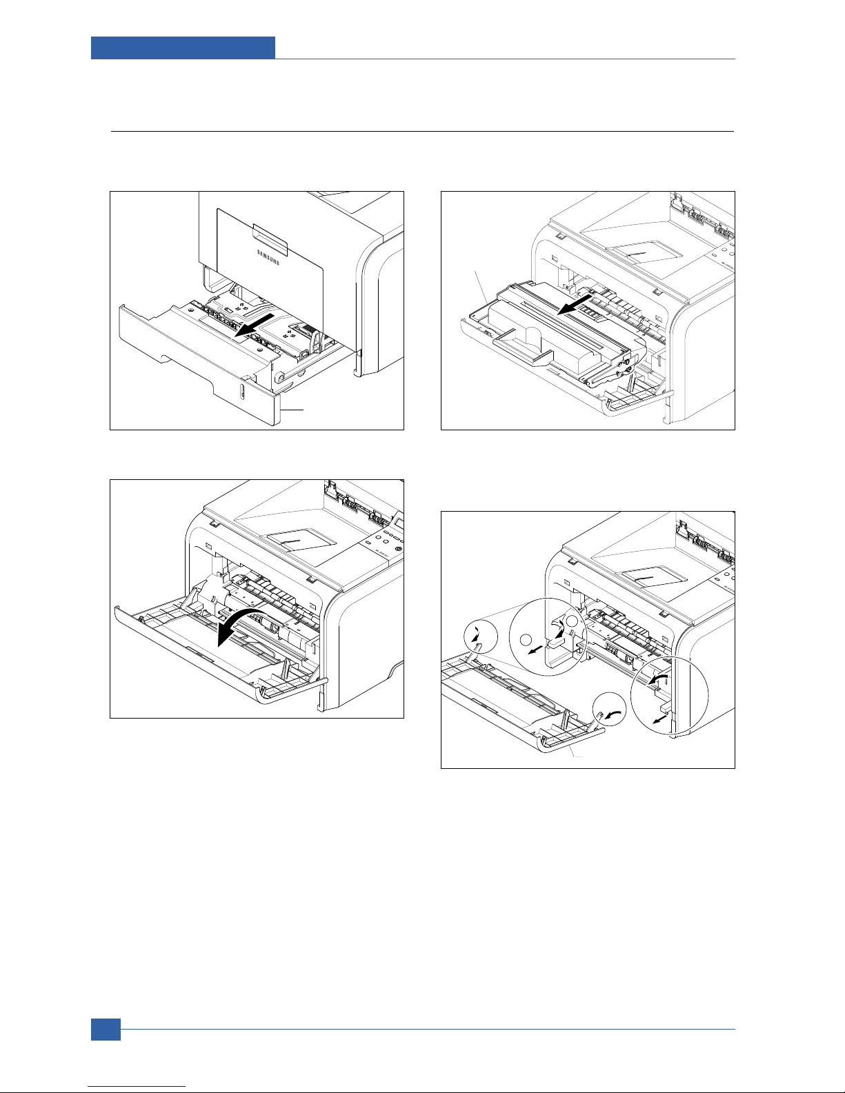
3.3 Front Cover
1. Take out the Cassette.
2. Open the Cover.
3. If necessary, remove the Toner Cartridge.
4. To remove the Front Cover, first pull the part below
the both side of the Front Cover with a light pressure to the direction of arrow.
Cassette
Toner Cartridge
Front Cover
2
1

Disassembly and Reassembly
Samsung Electronics
Service Manual
3-5
3.4 MP Tray Ass'y
1. Open the MP Tray Ass'y
2. Pull the Tray Links from the both side of the Front
Cover with a light pressure to the direction of arrow.
3. Apply light pressure to the both side of the MP Tray
Ass'y and pull it in the direction of arrow, as shown
below.
MP Tray Ass'y
Tray Link
MP Tray Ass'y

Samsung Electronics
Service Manual
Disassembly and Reassembly
3-6
3.5 Rear Cover
1. Take out the Duplex Unit.
2. Remove the four screws securing the Rear Cover
and then Release the Rear Cover from the Set.
3. To remove the Face Up Cover, first release the
Stopper Strap in the direction of arrow.
4. Unlatch the Face Up Cover from the Rear Cover
and then release the Face Up Cover, as shown
below.
Duplex Unit
Stopper Strap
1
2
Face Up Cover
Rear Cover

Disassembly and Reassembly
Samsung Electronics
Service Manual
3-7
3.6 Fuser Ass'y
1. Before you remove the Fuser Ass'y, you should open
the face up cover and open the guide output fuser.
- Rear Cover (Refer to 3.5)
2. Remove the four screws securing the Fuser Ass'y
and then pull the Fuser Ass'y.
3. Release the CON Harness and REC Harness from
the Thermostat and then remove the three screws
securing the Thermostat and remove it.
4. To remove the Electrodes, first release REC
Harness from the left side of the Electrode and
then release the CON Harness from the right side
of the Electrode, as shown below.
Fuser Ass'y
Thermostat
CON Harness
REC Harness
REC Harness

Samsung Electronics
Service Manual
Disassembly and Reassembly
3-8
6. Remove the two screws securing the IInput Guide
and remove it.
7. Unplug the connector from the Input Guide and
remove the one screw securing the Thermistor and
remove it.
8. Remove the three screws securing the Idle Gear
Bracket and remove it.
9. Remove the one screw securing the Fuser Cover
and release the Fuser Cover from the Fuser
Frame.
Input Guide
Thermister
Idle Gear Bracket
Fuser Cover
Fuser Frame
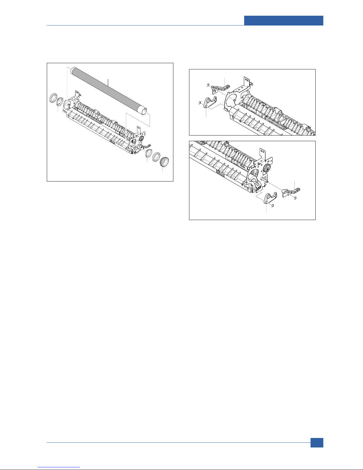
10. Release the Fuser Gear and HR Bush and then
remove the Heat Roller, as shown below.
11. Remove the Jam Link Lever (L,R) and Jam
Holder (L,R) and then remove the Pressure Roller,
as shown below.
Disassembly and Reassembly
Samsung Electronics
Service Manual
3-9
Heat Roller
HR Bush
HR Bush
Fuser Gear
Jam Holder
Jam Link Lever
Jam Holder
Jam Link Lever

Samsung Electronics
Service Manual
Disassembly and Reassembly
3-10
3.7 Top Cover
1. Before you remove the Top Cover, you should
remove:
- Rear Cover (Left, Right) (Refer to 3.5)
2. Remove the four screws securing the Top Cover,
as shown below.
3. To remove the Top Cover, first lift the Top Cover
with a light pressure to the direction of arrow. Then
unplug the OPE Harness, as shown below.
Top Cover

Disassembly and Reassembly
Samsung Electronics
Service Manual
3-11
3.8 OPE Unit
1. To remove the OPE Unit, first lift the OPE Unit with
a light pressure to the direction of arrow, Then
unplug the OPE Harness, as shown below.
Notice : When reassembly the OPE Unit, hole inside
of figure insert a harness.
2. Remove the six screws securing the OPE PBA and
LCD Panel to the OPE Cover and remove it, as
shown below.
3. Release the Lens and Keys from the OPE Cover.
OPE Unit
LCD Panel
OPE PBA
OPE Cover
Lens

Samsung Electronics
Service Manual
Disassembly and Reassembly
3-12
3.9 Side Cover (Left, Right)
1. Before you remove the Side Cover (Left, Right),
you should remove:
- Rear Cover (Refer to 3.5)
- Top Cover (Refer to 3.7)
2. Remove the one screw securing the Right Side
Cover, as shown below.
3. Apply light pressure to the bottom of the Right Side
Cover and pull it to the right side in the direction of
arrows, as shown below.
4. Remove the one screw securing the Left Side
Cover, as shown below.
5. Apply light pressure to the bottom of the Left Side
Cover and pull it to the left side in the direction of
arrows, as shown below.
Right Side Cover
Left Side Cover

Disassembly and Reassembly
Samsung Electronics
Service Manual
3-13
6. If necessary, pull the DIMM Cover in the direction
of arrow and remove it, as shown below.
Notice : Be careful not to damage the hooks when
remove the Side Cover (Left, Right).
DIMM Cover

Samsung Electronics
Service Manual
Disassembly and Reassembly
3-14
3.10 Shield Controller Ass'y
1. Before you remove the Shield Controller Ass'y, you
should remove:
- Side Cover Left (Refer to 3.9)
2. Unplug the all connectors from the Main PBA.
3. Remove the three screws securing the Shield
Controller Ass'y and remove it.
4. Remove the five screws securing the Main PBA to
the Shield and remove it.
5. The connectors are located, as shown below.
Shield Controller Ass'y
Shield
Insulator Sheet
Main PBA
LCD OPE
Cartridge
USB
Line
Duplex
Engine
BLDC
Pick Up
REGI
LSU S/W
LSU
Thermistor
MPF_SEN
MPF
LED OPE

Disassembly and Reassembly
Samsung Electronics
Service Manual
3-15
3.11 Drive Ass'y
1. Before you remove the Drive Ass'y, you should
remove:
- Side Cover Left (Refer to 3.9)
2. Remove the six screws securing the Drive Ass'y
and remove it.
Notice : The six screws have numbers stamped into
the Drive Ass'y base plate. When refitting the
Drive Ass'y tighten the screws the order they
are numbered. Only screws numbered 1 to 5
are fitted at this stage. Screw 6 is fitted when
the Shield Controller Ass'y is refitted.
3. If necessary, remove the four screws securing the
BLDC Motor Ass'y and remove it.
Drive Ass'y
Gear Bracket Ass'y
BLDC Motor Ass'y
Harness
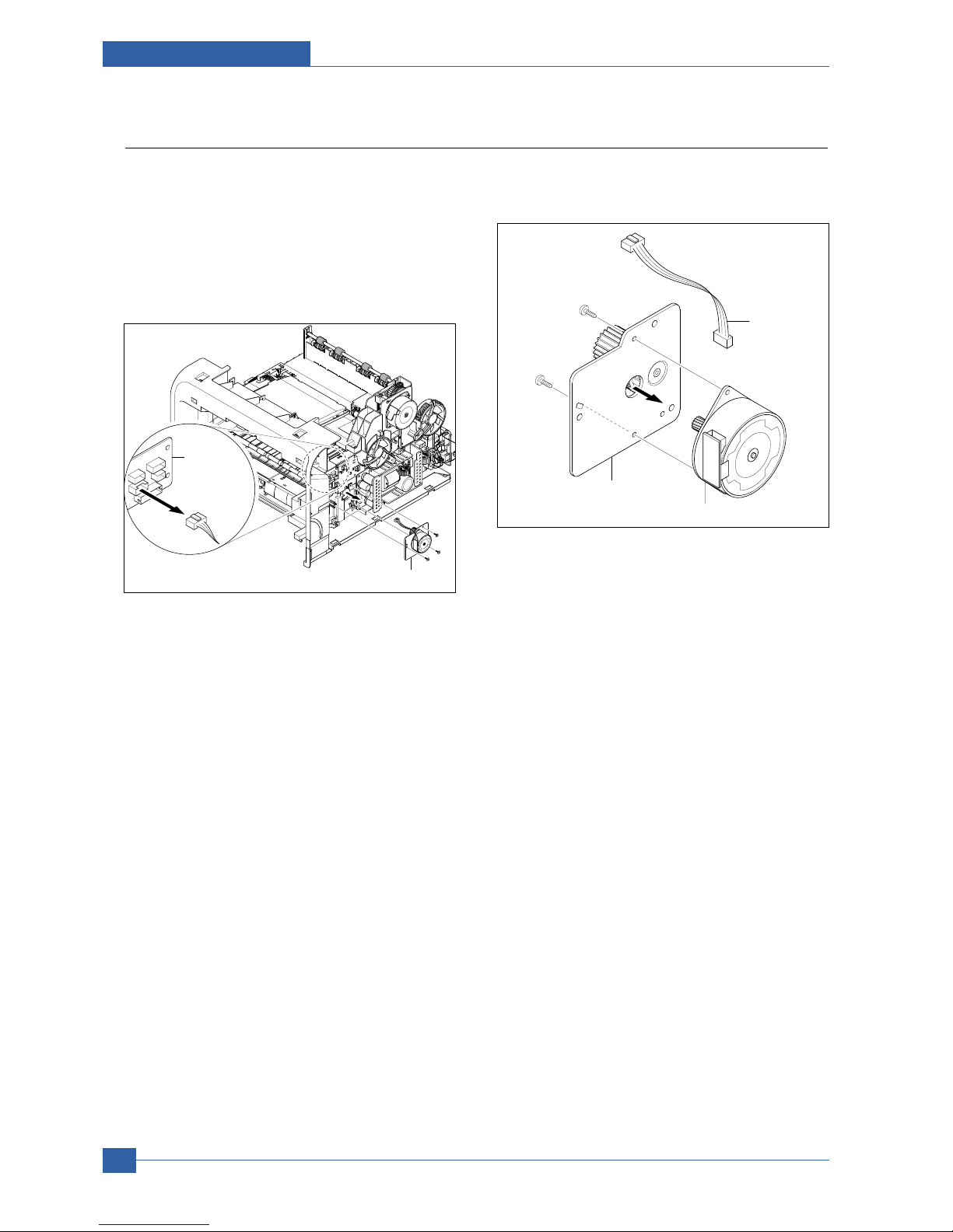
Samsung Electronics
Service Manual
Disassembly and Reassembly
3-16
3.12 Duplex Drive Ass'y
1. Before you remove the Duplex Drive Ass'y, you
should remove:
- Side Cover Right (Refer to 3.9)
2. Unplug the connector from the Connection PCB
and remove the three screws securing the Duplex
Drive Unit and remove it.
3. If necessary, remove the two screws securing the
Duplex Motor and remove it.
Duplex Drive Ass'y
Connection
PCB
Duplex Motor
Harness
Duplex Motor
Bracket Ass'y

Disassembly and Reassembly
Samsung Electronics
Service Manual
3-17
3.13 Shield SMPS Ass'y
1. Before you remove the Shield SMPS Ass'y, you
should remove:
- Side Cover Right (Refer to 3.9)
- Duplex Drive Ass'y (Refer to 3.12)
2. Unplug the two connectors (HVPS, Fuser).
3. Remove the three screws securing the Shield
SMPS Ass'y and remove it.
4. Unplug the connector (AC Inlet) and remove the
four screws securing SMPS and remove it.
HVPS Connector
Fuser Connector
Shield SMPS Ass'y
SMPS
Insulator Sheet
Shield SMPS (With AC Inlet)
AC Inlet Connector

Samsung Electronics
Service Manual
Disassembly and Reassembly
3-18
3.14 Connection PCB
1. Before you remove the Connection PCB, you
should remove:
- Side Cover Right (Refer to 3.9)
2. Unplug the all connectors.
3. Remove the two screws securing the Connection
PCB and remove it.
4. The connectors are located, as shown below.
Connection
PCB
Connection
PCB
FAN Duplex Exit Motor
Fan Main
HVPS
Duplex
Motor
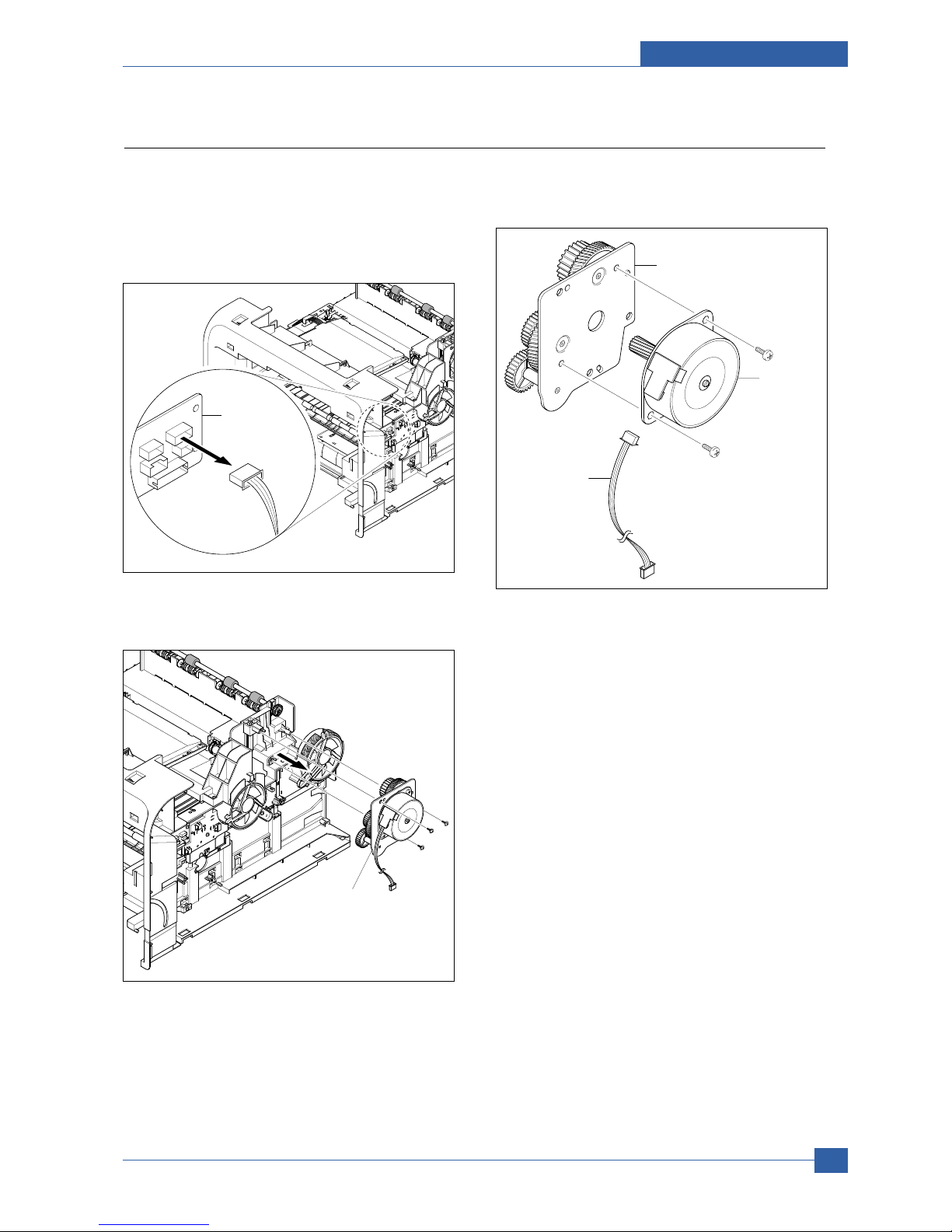
Disassembly and Reassembly
Samsung Electronics
Service Manual
3-19
3.15 Fuser Drive Ass'y
1. Before you remove the Fuser Drive Ass'y, you
should remove:
- Side Cover Right (Refer to 3.9)
2. Unplug the connector from the Connection PCB.
3. Remove the three screws securing the Fuser Drive
Ass'y and remove it.
4. If necnsary, remove the two screws securing the
Step Motor and remove it.
Fuser Drive
Connection
PCB
Fuser Drive Ass'y
Step Motor
Harness
Fuser Exit Bracket Ass'y
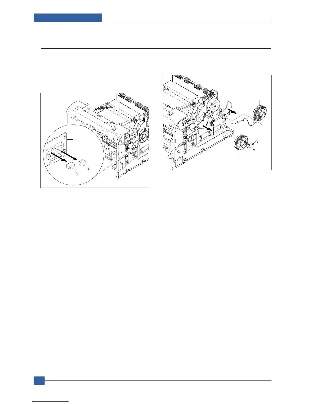
Samsung Electronics
Service Manual
Disassembly and Reassembly
3-20
3.16 Fan
1. Before you remove the Fan, you should remove:
- Side Cover Right (Refer to 3.9)
2. Unplug the two connectors from the Connection
PCB, as shown below.
3. Remove the two screws securing the Fans and
then pull the Fans (Main, Duplex).
Main Fan
Duplex Fan
Connection
PCB
Duplex Fan
Main Fan

Disassembly and Reassembly
Samsung Electronics
Service Manual
3-21
3.17 Pick Up Roller Ass'y
1. Take out the Cassette.
2. To remove the Pick Up Roller Ass'y, first lift the
notch attached to the Pick Up Roller Ass'y from the
Shaft, then slide the Pick Up Roller Ass'y from left
to right and it will be released completely, as shown
below.
3. To remove the Shaft, first release the locker and
slide the Shaft from left to right, then lift the notch
attached to the Cam so that it's released from the
Shaft. Then release the Bush from the Shaft and
remove the Shaft from the Duplex Guide Housing,
as shown below.
Pick Up Roller Ass'y
1
2
2
1
Cam
Bush
Shaft
Locker
3
4

Samsung Electronics
Service Manual
Disassembly and Reassembly
3-22
3.18 Duplex Guide Housing (With Feed Roller)
1. Before you remove the Duplex Guide Housing, you
should remove:
- Pick Up Roller Ass'y (Refer to 3.17)
2. Remove the two screws securing the Duplex Guide
Housing.
3. Unplug the one connector (Photo Interrupter) and
remove the Duplex Guide Housing (with Feed
Roller), as shown below.
4. Pull the Feed Roller from the Bushing.
Duplex Guide Housing
Photo Interrupter
Connector
Duplex Guide
Housing
1
2
Bushing
Feed Roller
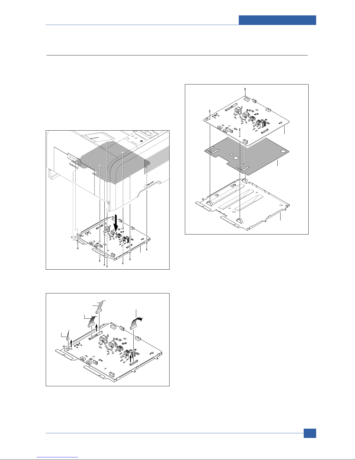
Disassembly and Reassembly
Samsung Electronics
Service Manual
3-23
3.19 HVPS Housing
1. Before you remove the HVPS Housing, you should
remove:
- Duplex Drive Ass'y (Refer to 3.12)
- Unplug the HVPS Connector (Refer to 3.13)
- Pick Up Roller Ass'y (Refer to 3.17)
- Duplex Guide Housing (Refer to 3.18)
2. Remove the eight screws securing the HVPS
Housing, as shown below.
3. Unplug the connector for connector PBA and SMPS
first. Unplug the other Connections.
4. If necessary, remove the three screws securing the
HVPS and remove it.
HVPS Housing
Duplex Motor
Connection PBA
& SMPS
Engine
Duplex Guide
Housing
HVPS
Insulator Sheet
Shield
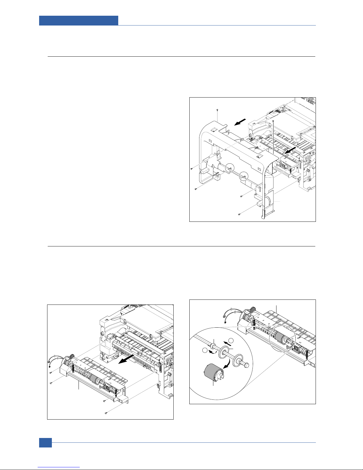
Samsung Electronics
Service Manual
Disassembly and Reassembly
3-24
3.20 Cover Mid Front
1. Before you remove the Cover Mid Front, you
should remove:
- Top Cover (Refer to 3.7)
- Side Cover (Refer to 3.9)
2. Remove the six screws securing the Cover Mid
Front and release two hooks in the center.
This cover is fragile take care when removing it.
Cover Mid Front
Hook
Hook
3.21 MPF Housing
1. Before you remove the MPF Housing, you should
remove:
- Cover Mid Front (Refer to 3.20)
2. Remove the four screws securing the MPF
Housing and remove it.
3. To remove the MP Pick Up Ass'y, first lift the notch
attached to the left side Stopper so that it's slide the
right to left from the Shaft, then left side Idle slid the
right to left from the Shaft and take out the MP Pick
Up Ass'y, as shown below.
MPF Housing
Stopper
1
2
Idle
MP Pick Up Ass'y
MPF Housing

Disassembly and Reassembly
Samsung Electronics
Service Manual
3-25
3.22 Feed Roller Parts
1. Before you remove the Feed Roller Parts, you
should remove:
- Pick Up Roller Ass'y (Refer to 3.17)
- Duplex Guide Housing (Refer to 3.18)
- Cover Mid Front (Refer to 3.20)
- MPF Housing (Refer to 3.21)
2. Remove the two screws securing the both side of
the Guide Paper and then remove the Guides.
3. Pull up the Feed Idle Shaft and the Bushs (with
Spring).
4. Release the E-Ring securing the Feed2 Gear and
remove it.
5. Remove the three screws securing the Feed
Bracket Unit and then remove the Feed Bracket
Unit and Feed2 Shaft.
Guide Paper
Feed Idle Shaft
Bush
Srring
Feed2 Gear
E-Ring
Feed2 Shaft
Feed Bracket Unit

Samsung Electronics
Service Manual
Disassembly and Reassembly
3-26
6. If necessary, release the three E-Rings securing
the Gears (T2 Idle, Retard, Idle) and then remove
the Gears from the Feed Bracket, as shown below.
Notice : Be aware of the E-Rings to ensure they are
not lost.
7. Remove the Clutch Unit, as shown below.
8. Pull up the Feed1 Roller from the Bushing, as
shown below.
T2 Idle Gear
Retard Gear
Idle Gear
E-Ring
Bracket
Feed Shaft
Feed1 Gear Ass'y
Clutch Unit
Feed1 Roller
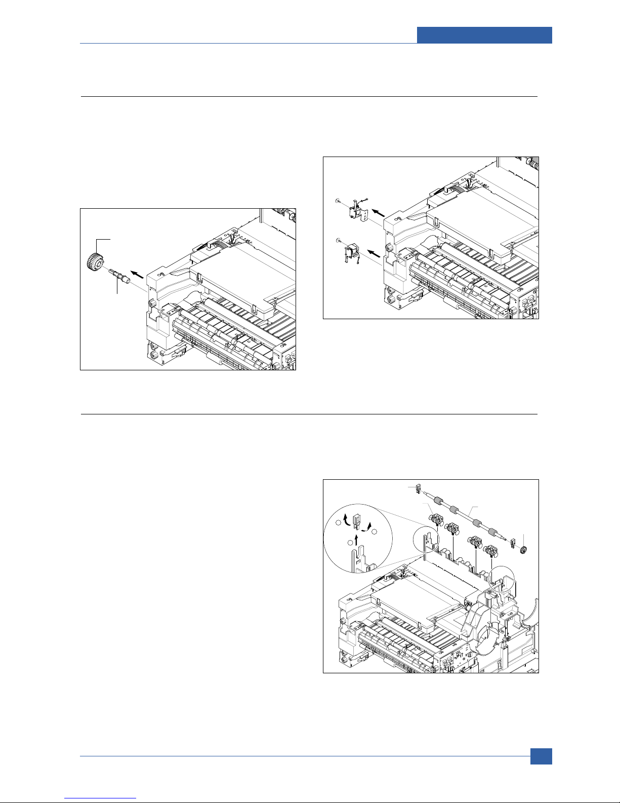
Disassembly and Reassembly
Samsung Electronics
Service Manual
3-27
3.23 Pick Up Gear Ass'y & Solenoids
1. Before you remove the Pick Up Gear Ass'y &
Solenoids, you should remove:
- Duplex Guide Housing (Refer to 3.18)
- Feed Bracket Unit (Refer to 3.22.5)
2. Release the Pick Up Gear Ass'y and Pick Up Gear
Shaft, as shown below.
3. Remove the two screws securing the Manual
Solenoid and Feed Solenoid and then remove the
Solenoids, as shown below.
Pick Up Gear Ass'y
Pick Up Gear Shaft
Feed Solenoid
Manual Solenoid
3.24 Exit Roller
1. Before you remove the Exit Roller, you should
remove:
- Top Cover (Refer to 3.7)
- Side Cover (Refer to 3.9)
- Fuser Drive Ass'y (Refer to 3.15)
2. Remove the Exit Gear, and release the Bearing at
one end then remove the Roller Exit F/Down and
Exit Roller Rack, as shown below.
1
2
1
Exit Gear
Roller Exit F/Down
Exit Roller Rack
Bearing
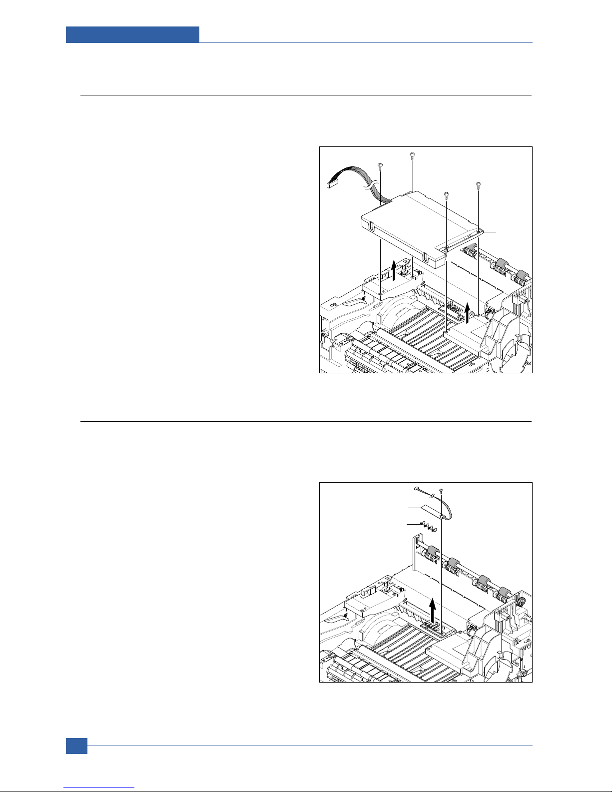
Samsung Electronics
Service Manual
Disassembly and Reassembly
3-28
3.25 LSU
1. Before you remove the LSU, you should remove:
- Top Cover (Refer to 3.7)
- Side Cover (Refer to 3.9)
2. Remove the four screws securing the LSU and
remove it.
LSU
3.26 TERMINAL
1. Before you remove the CRUM2 PBA, you should
remove:
- Top Cover (Refer to 3.7)
- Side Cover (Refer to 3.9)
- LSU (Refer to 3.25)
2. Remove the one screw securing the CRUM2 PBA
and remove it and then release the four Terminals,
as shown below.
Notice : Be aware of the Terminals to ensure they are
not lost.
CRUM2 PBA
Terminal

Disassembly and Reassembly
Samsung Electronics
Service Manual
3-29
3.27 Transfer Roller Parts
1. Before you remove the Transfer Roller Parts, you
should remove:
- Cover Mid Front (Refer to 3.20)
- LSU (Refer to 3.25)
2. Remove the three screws securing the Transfer Earth
and remove it.
3. Release the PTL Holder, as shown below.
4. To remove the Transfer Roller, first pull the TR Holder
and then take out the Transfer Roller, as shown
below.
Notice : Do not grab the rubber part of the Transfer
Roller, it may cause a malfunction due to a
foreigen object. Hole the both side of the
Transfer Roller when replacing it.
TR Holder
2
1
Transfer Roller
PTL Holder
Transfer Earth

Adjustment and Troubleshooting
Service Manual
4-1
Samsung Electronics
4
4
4. Adjustment and Troubleshooting
4.1 Alignment and Adjustments
4.1.1 Sample Pattern
This product has the several sample patterns for maintenance. With the sample patterns, check the
existence of the abnormality. The patterns help to regularly maintain the product.
4.1.1.1 Printing a Demo Page
Print a demo page or a configuration sheet to make sure that the printer is operating correctly.
Press the Menu button to selection (In formation -> Demo Page)

Service Manual
Adjustment and Troubleshooting
4-2
Samsung Electronics
4.1.2 Control Panel
4.1.2.1 Control Panel
ML-3470D and ML-3471ND
1
Menu: Enters Menu mode and scrolls through the available
menus.
2
Scroll buttons: Scroll through the options available in the
selected menu, and increase or decrease values.
3
OK: Confirms the selection on the display.
4
Back: Sends you back to the upper menu level.
5
Tone r Sa ve: Allows you to save on toner by using less toner
in printing.
6
ML-347x _Duplex: Allows you to print documents on both
sides of the paper.
7
Stop: Stops an operation at any time.
8
Status: Shows the status of your printer.

Adjustment and Troubleshooting
Service Manual
4-3
Samsung Electronics
4.1.2.2 System setup
This chapter provides step by step information on setting up your printer.
This chapter includes:
• Using control panel menus
• Menu overview
• Printing a demo page
• Changing the display language
• Using toner save mode
Using control panel menus
A number of menus are available to make it easy for you to change the printer settings. The diagram on the next column
shows the menus and all of the menu items available in each menu.
Accessing control panel menus
You can control your printer from the printer’s control panel. You can also set the control panel menus while the printer is
in use.
1. Press Menu until the menu you want appears on the bottom line of the display and press OK.
2. Press the Scroll buttons until the desired menu item appears and press OK.
3. If the menu item has sub menus, repeat step 2.
4. Press the Scroll buttons to access the desired setting option or the required value.
5. Press OK to save your selection.
An asterisk (*) appears next to the selection on the display, indicating that it is now the default.
6. Press Stop to return to Standby mode.
After 60 seconds of inactivity (no key being pressed), the printer automatically returns to Standby mode.

Service Manual
Adjustment and Troubleshooting
4-4
Samsung Electronics
4.1.2.3 Menu overview
The control panel menus are used to configure the printer. The control panel provides access to the following menus:
a. Available with the ML-347x.
b. Available with optional wireless network interface.
Information
Menu Map
Configuraton
Demo Page
PCL Font List
PS3 Font List
EPSON Font
Layout
Orientation
Simplex Margin
Duplex
sa
Duplex Margin
a
Emulation
Emulation Type
Setup
Paper
Copies
Paper Size
Paper Type
Paper Source
Tray Chaining
System Setup
Language
Power Save
Auto Continue
Jam Recovery
Altitude Adj.
Auto CR
Job Timeout
Maintenance
Clear Setting
Graphic
Resolution
Darkness
Image Enhance
Network
TCP/IP
EtherTalk
NetWare
Ethernet Speed
Wireless
b
Clear Setting
Network Info

Adjustment and Troubleshooting
Service Manual
4-5
Samsung Electronics
4.1.2.4 Basic Operation of Panel
ML-3470D ML-3471ND
Status” LED Description
Off Power Off / Sleep Mode (When data receive it’ll Wake-up)
Green On Ready status
Blink Blink Slowly : Data Comm. status
Blink Fast : Printing status
Red On Error which needs user action
(Toner Empty, Paper Jam, Paper Empty, Cover Open etc..)
Blink Recoverable Error
(Paper Mismatching, Manual printing in MP Tray)
Warning status
Warning just like supplies exchange (Toner Low etc.)
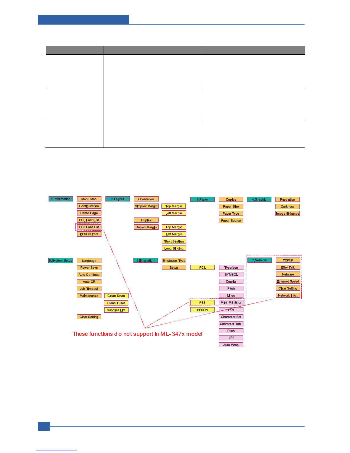
Service Manual
Adjustment and Troubleshooting
4-6
Samsung Electronics
Error Type Legacy models Error Platform model Error
Recoverable Error Error which can be recoverable Error which doesn’t need any special user
Ex) Jam, Paper Empty, etc. actions
Ex) Paper Mismatching, Manual printing in
MP Tray
Error Just like hardware error which can not be Including provider service error which need
fixed even if user does special action some special user or provider actions
Ex) Hsync Error, LSU Error, etc. Ex) Toner Empty, Paper Jam, Paper Empty,
Cover Open, etc.
Assert behavior LCD model LCD model
- It shows the task name and the lines in - It shows the task name and the lines in LCD
LCD display display
Operation Map
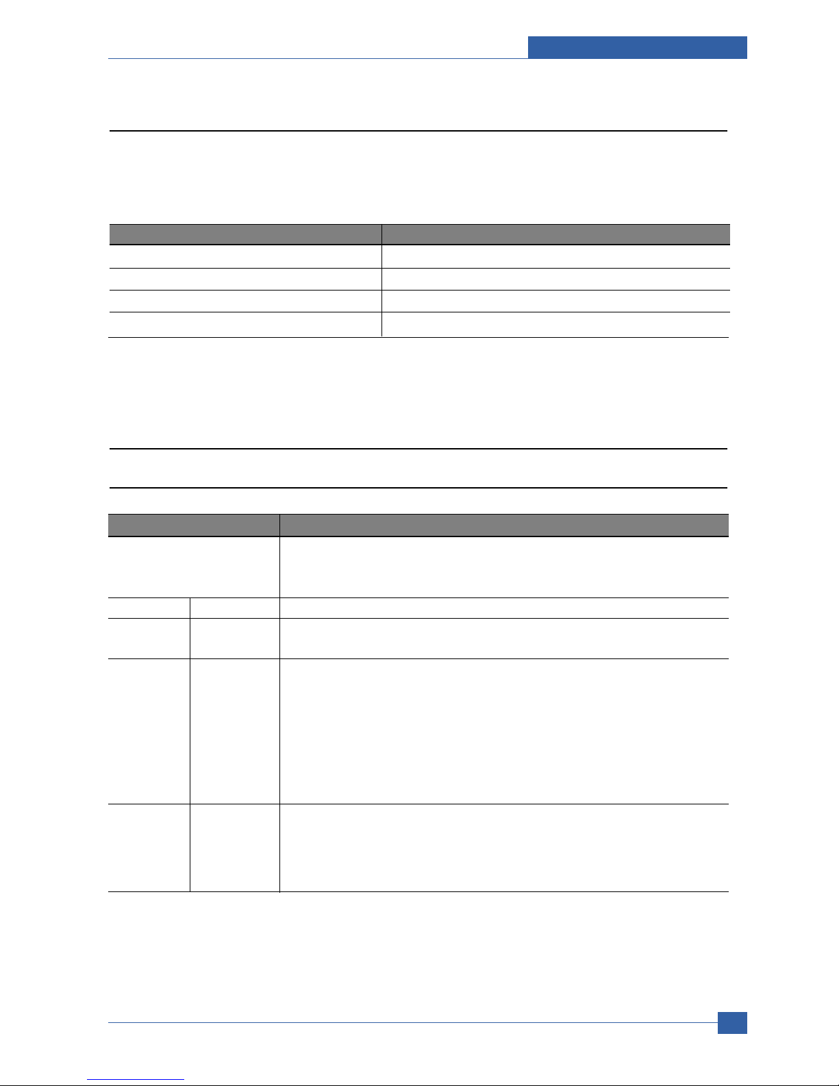
Adjustment and Troubleshooting
Service Manual
4-7
Samsung Electronics
COMPONENT REPLACEMENT CYCLE
Pick-up Roller 150K Pages
Transfer Roller 70K Pages
Fuser 80K Pages
Toner Cartridge 10K Pages(Sales), 4K Pages(Initial)
4.1.3 Consumables and Replacement Parts
To avoid print quality and paper feed problems resulting from worn parts and to maintain your printer in top working
condition the following items will need to be replaced at the specified number of pages or when the life span of each
item has expired.
4.1.4 LED Status Error Message
4.1.4.1 Status LED
Status Description
Off • The printer is off-line and cannot print.
• The printer is in power save mode. When data is received, it switches to on-line
automatically.
Green On The printer is on-line and can receive data from the computer.
Blinking • When the backlight blinks slowly, the printer is receiving data from the computer.
• When the backlight blinks quickly, the printer is receiving and printing data.
Red On • The toner cartridge is totally exhausted.
Remove the old toner cartridge and install a new one.
• A paper jam has occurred. To solve the problem.
• The front cover is open. Close the front cover.
• There is no paper in the tray. Load paper in the tray.
• The printer has stopped printing due to a major error. Check the display message.
for details on the meaning of the error message.
Blinking • A minor error is occurring and the printer is waiting for the error to be cleared. Check
the display message. When the problem is cleared, the printer resumes printing.
• The toner cartridge is low. Order a new toner cartridge. You can temporarily improve
print quality by redistributing the toner.

Service Manual
Adjustment and Troubleshooting
4-8
Samsung Electronics
4.1.4.1 Error Message
Message Meaning Suggested solutions
Door Open The front cover or rear cover is not Close the cover until it locks into place.
securely latched.
Duplex Jam 0 Paper has jammed during duplex Clear the jam.
Check Inside printing.
Duplex Jam 1 Paper has jammed during duplex Clear the jam.
Open/Close Door printing.
Fuser Door Open The fuser door is not securely latched. Open the rear cover and close the fuser door until
it locks into place.
For the location of the fuser door.
Install Toner A toner cartridge is not installed. Install a toner cartridge.
Invalid Toner The toner cartridge you have installed is Install a Samsung-genuine toner cartridge,
not for your printer. designed for your printer.
Load Manual Press The multi-purpose tray is empty in Load a sheet of print material and press Stop
Stop Key manual feed mode. You need to press Stop each page to be printed.
Low Heat Error There is a problem in the fuser unit. Replace to Fuser Unit.
Cycle Power
LSU Hsync Error A problem has occurred in the LSU Replace to LSU Unit.
Cycle Power (Laser Scanning Unit).
LSU Motor Error A problem has occurred in the LSU Replace to LSU Unit.
Cycle Power (Laser Scanning Unit).
Main Motor Locked There is a problem in the main motor. Open and then close the front cover.
Open Heat Error There is a problem in the fuser unit. Unplug the power cord and plug it back in.
Cycle Power If the problem persists, please call for service.
Over Heat Error There is a problem in the fuser unit. Unplug the power cord and plug it back in.
Cycle Power If the problem persists, please call for service.
Paper Jam 0 Paper has jammed in the feeding area Clear the jam.
Open/Close Door of the tray.
Paper Jam 1 Paper has jammed in the fuser area. Clear the jam.
Open/Close Door
Paper Jam 2 Paper has jammed in the paper exit Clear the jam.
Check Inside area.
Printing... The printer is printing jobs using Complete your printing.
the displayed language.
Ready The printer is on-line and ready to Use your printer.
printer.
Replace Toner This message appears between the Replace the toner cartridge with a new one.
Toner Empty and Toner Low status.
Self Diagnostic... The engine in your printer is checking Please wait a few minutes.
some problems detected.

Adjustment and Troubleshooting
Service Manual
4-9
Samsung Electronics
Message Meaning Suggested solutions
Sleeping... The printer is on power save mode. When data is received, it switches to on-line
automatically.
Toner Empty The toner cartridge has run out. Replace the toner cartridge with a new one.
The printer stops printing.
Toner Low The toner cartridge is almost empty. Take out the toner cartridge and thoroughly
shake it. By doing this, you can temporarily
reestablish printing operations.
Tray 1 Paper Empty There is no paper in the tray 1. Load paper in the tray 1.
Tray 2 Paper Empty There is no paper in the optional tray 2. Load paper in the optional tray 2.

Service Manual
Adjustment and Troubleshooting
4-10
Samsung Electronics
1
2
3
4
OPC Drum
Charge Roller
Supply Roller
Developing Roller
5
6
7
Transfer Roller
Heat Roller
Pressure Roller
1
2
3
4
5
6
7
4.1.5 Abnormal Image Printing and Defective Roller
If abnormal image prints periodically, check the parts shown below.
No Roller Abnormal image period Kind of abnormal image
1 OPC Drum 75.5mm White spot, Block spot
2 Charge Roller 37.7mm Black spot
3 Supply Roller 44.9mm Horizontal density band
4 Develop Roller 35.2mm Horizontal density band
5 Transfer Roller 47.1mm Black side contamination/transfer fault
6 Heat Roller 77.8mm Black spot and fuser ghost
7 Pressure Roller 62.8mm / 50.24mm Black side contamination

Adjustment and Troubleshooting
Service Manual
4-11
Samsung Electronics
4.1.6 How to use DCU
4.1.6.1 DCU Setup
You can examine the malfunction of the printer. To perform DCU, open the front discharge cover and leave the
connect the harness wire(10 pin/4 pin) to the CN1(ML-347x) of the Main control board.
ML SERIES DIAGNOSTIC CONTROL UNIT
04
05
07
08
09
10
DEV 300
LSU READY
PAPER EMPTY
COVER OPEN
COER HEATING
DEV 350
LSU MT & LD
PAPER WIDTH
EXIT SENSOR
PRINTING TEMP
DEV 350
LSU MOTOR
NEW CRU
FEED SENSOR
READY HEAT
ON
OFF
STAT US
SELF
TEST
DIAGNOSTIC
DIAGNOSTIC CODE
00
01
02
03
04
05
06
07
08
09
10
11
12
13
14
61
00
01
02
03
04
20
30
40
50
69
60
62
68
64
70
71
72
73
95
MAIN MOTOR OPERATING SYSTEM
MAIN HIGH-VOLTAGE ON
TRNSFER HIGH-VOLTAGE (-)ON
THV(+) REFERANCE VOLTAGE
DEV/SUPPLY HIGH-VOLTAGE ON/PTL ON
LSU OPERATING SYSTEM
PICKUP CLUTCH ON
PEEMPTY/PWITH/NEW CRU TEST
FEED & EXIT SENSOR TEST
COVER OPEN SENSOR TEST
FUSER TEST
HOT BURN TEST
CLEAN MODE PRINT
THV(+)TRIGGER, ALL HV & FAN ON
THV(+) REFERENCE ON
ERROR STATUS CODE
STATUS CODE
WARM UP
READY (REGAL)
READY (LETTER)
READY (A4)
READY (EXECUTIVE)
READY (B5)
PRINT START
FEED SENSOR ON
FEED SENSOR OFF
PAPER OUT
SLEEP MODE
OPEN FUSER ERROR
LOW TEMPERATURE ERROR
OVER HEATING ERROR
COVER OPEN ERROR
NO PAPERR
PAPER JAM 0
PAPER JAM 1
PAPER JAM 2
LSU NOT READY
DIAGNOSTIC
MODE
DOWN
UP ENTER
SHIFT STOP
TO ENTER DIAGNOSTIC MODE, PUSH THREE BUTTONS SIMUL ANEOUSL
AND TURN THE PRINTER POWER ON.

Service Manual
Adjustment and Troubleshooting
4-12
Samsung Electronics
4.1.6.2 Code
Connect DCU to the printer and turn the power on. It show 7 Segment FND on the panel and each code tells the
function of the printer.
1) Normal Code
While printing or warming up, it indicate the position of the paper
2) Error Code
When detecting the malfunction, the printing is stopped to indicate error code.
Code State Description
61 Warm up The printer is on, the cover is open or close.
00~05 Ready(kind of paper) The printer is ready, the paper is detected when the first paper is printed.
00: Legal ,01: Letter ,02: A4 ,03: EXEC ,04: B5 ,05: Folio, 06: A5/A6
20, 21, 22 Print Start The engine controller received the print order from the video controller.
20: 1st, 21: MP, 22: SCF
30 Feed Sensor On The paper is passing out of the Feed Sensor.
40 Feed Sensor off The paper has passed out of the Feed Sensor.
50 Paper Out The paper has passed out of Exit Sensor.
69 Sleep Mode The fuser power turned off to minimize the power consumption.
Code State Description
60, 62, 68 Fuser Error The error in the fuser occurred. There is a short circuit in the thermistor
and the thermostat while printing, Low Temperature Error occurs.
• 60: Open Fuser Error
• 62: Low Heat Error
• 68: Over Heat Error
64 Cover Open The Printer Cover is open.
65 CRU Error The Toner Cartridge not installed,
70 No Paper No paper in the paper cassette.
71 Paper Jam 0 The front part of paper is jammed between pickup unit and Feed sensor.
72 Paper Jam 1 The front part of paper is jammed between the Discharge sensor and Feed
sensor.
73 Paper Jam 2 The front part of paper is jammed just after passing through the discharge
sensor.
76 Out Bin Full The Out bin is filled with paper.
95 LSU Not Ready LSU Scanner Motor not ready or Hsync signal not output.

Adjustment and Troubleshooting
Service Manual
4-13
Samsung Electronics
4.1.6.3 Self Diagnostic Mode
If Error code occurs due to malfunction of the printer, perform Self Diagnostic Mode to solve the problem.
The printer works only in the self-test mode to solve the malfunction problem.
To enter the self-test mode, turn the power on pressing the buttons of [Down], [Shift] and [Stop] at the same time.
Release the button within 2 or 3 seconds if 78 shows in the DCU. If 00 shows in the DCU, press the button [Up] or
[Shift] to select the self+test , and press the button of [Enter] to operate. To stop, press the button of [shift] and
[Enter] together.
Code Description
00 Main Motor Operating System
Only the main motor is in operation.
01 Main High Voltage On(THV-)
-1400 voltage output by MHV terminal.
Caution : High voltage probe should be used.
02 Transfer High Voltage(-)On(THV-)
-1000 voltage output by MHV terminal.
Caution : High voltage probe should be used.
03 Transfer High Voltage (+)Reference on (THV +)
+1300 voltage output by MHV terminal.
Caution : High voltage probe should be used.
04 DEV/supply High Voltage : DEV/Supply High Voltage Test.
The left one of the three LEDs in the self-test panel is on when DEV high voltage Supply
high voltage output by each HV terminal. Press the [Up] button to switch the voltage. The
middle and right one of the three LEDs are on and -350 voltage output by DEV HV
terminal.
Caution : High voltage probe should be used.
05 LSU Operating System
The scanning motor of LSU is in operation, the right LED of the three buttons on. Press
the [Up] button to Check LD. LD is functioning and the middle button is on. If the LD is
normal, all LEDs are on.
06 Pickup clutch on
The Solenoid in the printer is in operation. To stop the operation, Press the button [shift]
and [Enter] together.

Service Manual
Adjustment and Troubleshooting
4-14
Samsung Electronics
Code Description
07 Paper Empty Sensor Test :
If activate the Actuator of the PEMPTY Sensor, the left and right of the three LEDs are
on.
Paper Empty Sensor ON/OFF 1st LED ON/OFF
08 Feed & Exit Sensor Test
Test the Feed sensor and Discharge sensor in the same way as '07'.
Feed Sensor ON/OFF 2nd LED ON/OFF
Exit Sensor ON/OFF 3rd LED ON/OFF
09 Cover Open Sensor Test
Test the Cover Open Sensor in th same way as code '07’
Cover Open Sensor ON/OFF1st LED ON/OFF
10 Fuser Test
If the [Enter] button pressed, the right LED is on and temperature of the fuser is up to
READY Mode. If the [Up] button pressed, the middle LED is on and temperature of the
fuser is up to Printing Mode.
If you press the button once more, the left LED is on and temperature of the fuser is up to
overheat Mode.
11 Hot Burn Test
If the [enter] button pressed, the printer is continuously printing without detection.
Turn the power off to stop operation.
12 Cleaning Mode Print Mode
Print the paper to clean the OPC Drum in the Cartridge.
13 THV(+) TRIGGER. ALL HV :
All high voltage output by each HV terminal and LSU and the fan is in operation. In this
mode, electronic resistance of transfer roller and high voltage is detected.
14 PTL Test : (ML-1610 : not design)
Indicates the function of the PTL, same method of the code ‘07’.
15 Fan Test :
Indicates the function of the Fan, same method of the code ‘07’.
16 Manual Pickup Test :
Indicates the function of th Manual Pickup, same method of the code ‘07’.
17 Manual Sensor Test :
Indicates the function of the Manual Sensor, same method of the code ‘07’.

Adjustment and Troubleshooting
Service Manual
4-15
Samsung Electronics
No. Ent er Up/Down Stop Re mark
00
Motor
Motor Run Motor Stop
01
MHV
Mhv On Mhv Off -
-1000V
-350V
020mV
130 0 V
02
THV(-)
Thv Negative On Thv Negative Off
03
THV(+)
Thv On Thv Of f +1300V
04
DEV
Dev On
Supply DE V
Dev Off
0:-550V 0:-350V
05
LSU
LSU R u n
On Off Ready
LSU St op
06
PickUp
Pickup On Pickup Off
07
PEmpty
Paper Em pt y
08
Sensor
Exit Fee d
09
Cover
Cover Open
10
Fuser
Fuser On Fuser O ff
11
Hot Burn
Hot Burn On
12
Clean Print
Clean Printing
13
Thv
Reference
low
adequate
high
14
PTL
PTL On PTL Off PTL No
15
FAN
Fan On Fan Off
16
Pic kUp
Manual Pickup On Manual Pickup O ff
17
Manual
Manual
Sensor
Manual Sensor
Function
4.1.6.4 Self Test Button
If the Self-Test button pressed, vertical lines are printed.
Turn the power on while pressing this button, '89' shows in the DCU and the printer is warming up. After warmingup the printer is in READY Mode, and '88' shows in the DCU. In this mode, without any detection, the printer begins
printing(trial printing and data from the PC). It is convenient to use this mode when the engine malfunction is
detected in the control board.

Service Manual
Adjustment and Troubleshooting
4-16
Samsung Electronics
4.1.7 Paper Jam
4.1.7.1 Clearing paper jams
Message Location of Jam
Paper Jam 0 In the paper feed area
Open/Close Door (tray 1, optional tray 2, multi-purpose tray)
Paper Jam 1 Around the toner cartridge
Open/Close Door Check Inside In the paper exit area
Paper Jam 2
Duplex Jam 0 In the duplex area
Check Inside a
Duplex Jam 1 Between the duplex unit and fuser area
Open/Close Door
a
Roller-Heat
Roller-Exit
Roller-Transfer
Roller-Pickup
Roller-Feed
Roller-MP
Roller-Pressure
Roller-REGI
OPC
Duplex
Duplex
Roller-REGI
OPC

Adjustment and Troubleshooting
Service Manual
4-17
Samsung Electronics
In the tray 1
1. Pull the tray 1 open.
2. Remove the jammed paper by gently pulling it
straight out. Make sure that all of the paper is
properly aligned in the tray 1.
If the paper does not move when you pull, or if you
do not see the paper in this area, check the fuser
area around the toner cartridge.
3. Insert the tray 1 into the printer until it snaps into
place. Printing automatically resumes.
In the optional tray 2
1. Pull the optional tray 2 open.
2. Remove the jammed paper from the printer.
If the paper does not move when you pull, or if you
do not see the paper in this area, stop and go to
step 3.
3. Pull the tray 1 half.
4. Pull the paper straight up and out.
5. Insert the trays back into the printer. Printing
automatically resumes.
In the multi-purpose tray
1. If the paper is not feeding properly, pull the paper
out of the printer.
2. Open and close the front cover to resume printing.
4.1.7.2 In the paper feed area

Service Manual
Adjustment and Troubleshooting
4-18
Samsung Electronics
1. Open the front cover and pull the toner cartridge
out.
2. Remove the jammed paper by gently pulling it
straight out.
3. Replace the toner cartridge and close the front
cover. Printing automatically resumes.
4.1.7.3 Around the toner cartridge
1. Open and close the front cover. The jammed paper
is automatically ejected from the printer.
2. Gently pull the paper out of the output tray.
If you do not see the jammed paper or if there is
any resistance when you pull, stop and go to the
next step.
3. Open the rear cover.
4. If you see the jammed paper, push the pressure
lever on each side up and remove the paper.
Return the pressure lever to its original position and
skip the step 10.
If you still do not see the paper, go to the next step.
4.1.7.4 In the paper exit area
1
pressure lever

Adjustment and Troubleshooting
Service Manual
4-19
Samsung Electronics
5. Release the blue strap, the rear cover stopper, and
fully open the rear cover, as shown.
6. Unfold the duplex guide fully.
7. While pushing the fuser lever to the right, open the
fuser door.
8. Pull the jammed paper out.
If the jammed paper does not move when you pull,
push the pressure lever on each side up to loose
the paper, and then remove it.
9. Return the lever, door, stopper, and guide to their
original position.
10. Close the rear cover. Printing automatically
resumes.
1
rear cover stopper
2
rear cover
2
1
1
duplex guide
1
1
fuser lever
2
fuser door
2
1
1
pressure lever
1

Service Manual
Adjustment and Troubleshooting
4-20
Samsung Electronics
Duplex jam 0
1. Pull the duplex unit out of the printer.
2. Remove the jammed paper from the duplex unit.
If the paper does not come out with the duplex unit,
remove the paper from the bottom of the printer.
Duplex jam 1
1. Open the rear cover.
2 Unfold the duplex guide fully.
3. Pull the jammed paper out.
1
duplex unit
1
4.1.7.5 In the duplex unit area
If the duplex unit is not inserted correctly, paper jam may occur. Make sure that the duplex unit is inserted correctly.
1
1
duplex guide

Adjustment and Troubleshooting
Service Manual
4-21
Samsung Electronics
4.1.7.6 TiPs for avoiding paper jams
By selecting the correct media types, most paper jams can be avoided.
• Follow the procedures on page 5.5. Ensure that the adjustable guides are positioned correctly.
• Do not overload the tray. Ensure that the paper level is below the paper capacity mark on the inside wall of the
tray.
• Do not remove paper from the tray while your printer is printing.
• Flex, fan, and straighten paper before loading.
• Do not use creased, damp, or highly curled paper.
• Do not mix paper types in a tray.
• Use only recommended print media.
• Ensure that the recommended print side of print media is facing down in the tray, or facing up in the multi-purpose
tray.
• If paper jams occur frequently when you print on A5-sized paper: Load the paper into the tray with the long edge
facing the front of the tray.
In the printer properties window, set the page orientation to be rotated 90 degrees.

Service Manual
Adjustment and Troubleshooting
4-22
Samsung Electronics
4.1.8 Download & Reset F/W
Reset method
1. In Dos Prom pt ty pes "Usblist2 [ Rom fil e name] " and Press
Enter
2. In LCD " Flash Upgrade..." mes sage will be show up.
3. In LCD " Update Image Pleas e Wait..." message will be
show up.
4. When download complet e, set will be automatically p ower
On/O ff a nd it' ll Warming Up
LCD Panel
Boot
Download
method
1. In LCD " Update Image Pleas e Wait..." message will be
show up.
2. In LCD message Ready¡ Printing then print out
conf iguration page
3. Check th e OS version and total pa ge value is "0"
4. Please set pow er On/ Off
LCD Panel
1. While Pressing Stop k ey, Power O n the Printer
2. After veri fy the m essage "Download Mode Press Stop key"
Press Stop Key
3. Verify the m essage "Download Mode Plese Send IMG..."
4. In Dos Prom pt ty pes "Usblist2 [ Rom fil e name] " and Press
Enter
5. In LCD " Update Image Pleas e Wait..." message will be
show up.
6. When download complet e, set will be automatically p ower
On/O ff a nd it' ll Warming Up
LCD Panel
Normal
Download
method
Firmware downloa d method
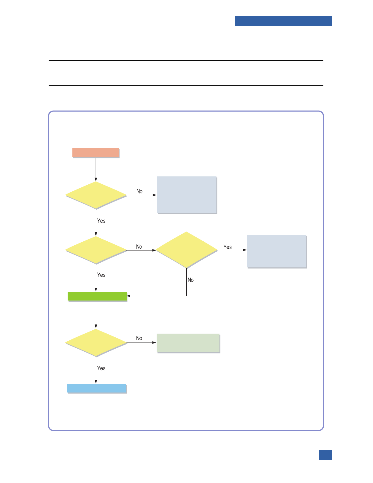
Adjustment and Troubleshooting
Service Manual
4-23
Samsung Electronics
4.2 Troubleshooting
4.2.1 Procedure of Checking the Symptoms
Before attempting to repair the printer first obtain a detailed description of the problem from the customer.
Power On
- No Power
- Power Module error
- Main PBA error
- LCD Panel error
Refer to "Solution
of Image Problem"
OP Panel
ON?
Ready or
Power save
Indicate
Error Massage
Refer to
Error Massage
<Chapter 4.1.4>
Test Print
END
printing
Quality is
Nomal?

Service Manual
Adjustment and Troubleshooting
4-24
Samsung Electronics
4.2.2 The cause and solution of Bad image
1) Vertical Black Line and Band
Description: 1. Straight thin black vertical line occurs in the printing.
2. Dark black vertical band occur in the printing.
3. Partly depression or
deformation on the surface of
the transfer roller.
2. Scratched surface of
the charge roller in the toner cartridge.
1. Damaged develop roller in
the Toner cartridge. Deformed Doctor-blade
or cleaning-blade.
If causes 1 and 2 occur in the
toner cartridge, replace the toner
cartridge and try to print out.
Replace the transfer roller if
occurred as No. 3.
Digital Printer
Digital Printer
Digital Printer
Digital Printer
Digital Printer

Adjustment and Troubleshooting
Service Manual
4-25
Samsung Electronics
2) Vertical White Line
Description: White vertical voids in the image.
3. It may occur when Burr and
foreign substances are on the window
of the toner cartridge frame.
4. If the fuser is defective,
voids occur periodically at the
top of a black image.
5. It may occur when foreign
substances are on the OPC Drum.
6. Partly depression or
deformation on the surface of the
transfer roller
2. Foreign matter or
toner particles between the toner
cartridge roller and blade. (In case the life of the
toner cartridge has been expired, white
lines or light image occur in
front of the image.)
1. Foreign matter stuck onto the
window of internal lenses
of LSU mirror.
Foreign matter stuck onto the
window : Clean the LSU window
with recommended cleaner(IPA)
Clean the window with a clean
cotton swab.
Replace the toner cartridge.
No 3. : Remove the foreign matter
and burr of the exposure window.
(toner cartridge)
No. 4. : Open the front cover and
check ribs that corresponds to the
position of the voids. Remove if
found.
If the problems are not solved,
replace the toner cartridge.
Replace the transfer roller if
occured as NO.6
Digital Printer
Digital Printer
Digital Printer
Digital Printer
Digital Printer
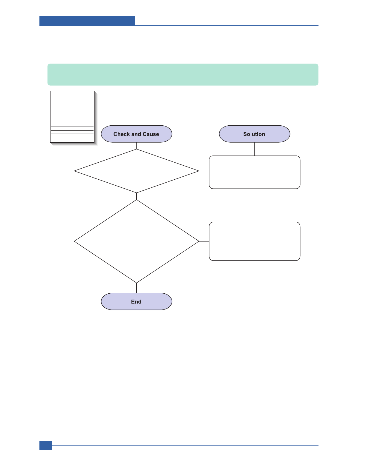
Service Manual
Adjustment and Troubleshooting
4-26
Samsung Electronics
3) Horizontal Black Band
Description: Dark or blurry horizontal stripes occur in the printing periodically.
(They may not occur periodically.)
2. The rollers of toner
cartridge may be stained.
Charge roller = 37.7mm
Supply roller = 44.9mm
Develop roller = 35.2mm
Transfer roller = 47.1mm
1. Bad contacts of the voltage
terminals to toner cartridge.
Clean each voltage terminal of the
Charge, Supply, Develop and
Transfer roller. (remove the toner
particles and paper particles)
1. Clean the right Gear that has
relatively small gap of the teeth
in the OPC.
2. If the malfunction persists,
replace the toner cartridge.
Digital Printer
Digital Printer
Digital Printer
Digital Printer
Digital Printer
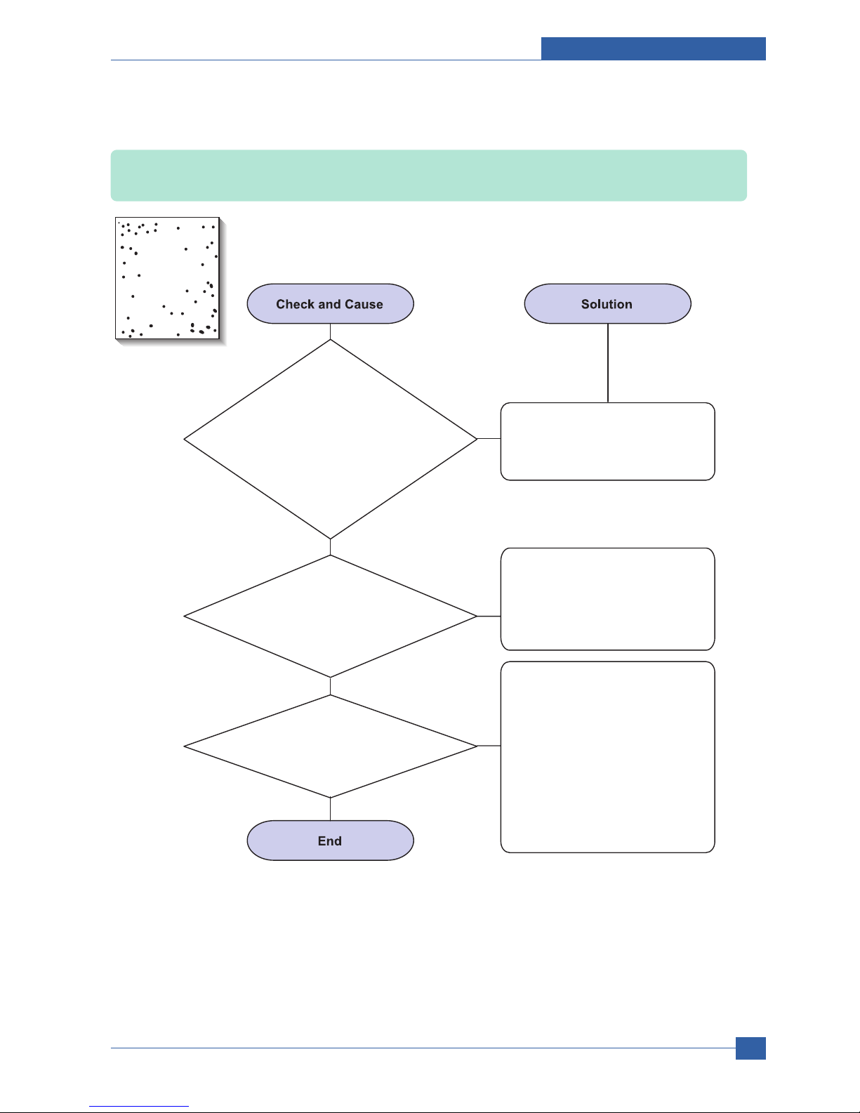
Adjustment and Troubleshooting
Service Manual
4-27
Samsung Electronics
4) Black/White Spot
Description: 1. Dark or blurry spots occur periodically in the printing
2. White spots occur periodically in the printing
2. If faded areas or
voids occur in a black image
at intervals of 95 mm, or black spots
occur elsewhere, the OPC drum
surface is damaged.
3. If a black image is
partially broken, the transfer
voltage is abnormal or the transfer
roller's life has expired.
1. If dark or blurry
black spots occur periodically,
the rollers in the Toner cartridge may oner cartridge may
be contaminated with foreign matte or be contaminated with foreign matte or
paper particles.
( Charge roller : 37.7 mm interval ( Charge roller : 37.7 mm interval
OPC drum : 75.5 mm interval) OPC drum : 75.5 mm interval)
1. If dark or blurry
black spots occur periodically,
the rollers in the Toner cartridge may
be contaminated with foreign matte or
paper particles.
( Charge roller : 37.7 mm interval
OPC drum : 75.5 mm interval)
Run OPC cleaning Mode Print
and run the Self-test 2 or 3 times.
In case of 95 mm interval
unremovable in 1, cleanly remove
foreign substances stuck on the
OPC location equivalent to black
spots and white spots with a dry
duster.
1. The transfer roller guarantees
100,000 sheets printing. If the
roller's life is expired, replace it.
2. In case of 95 mm interval
unremovable in 1, take measures
as to replace the toner cartridge
and try to print out.
3. Clean the inside of the set
against the paper particles and
foreign matter in order not to
cause the trouble.
Digital Printer
Digital Printer
Digital Printer
Digital Printer
Digital Printer

Service Manual
Adjustment and Troubleshooting
4-28
Samsung Electronics
5) Light Image
Description: The printed image is light, with no ghost.
2. Ambient temperature is below than 10°C.
3. Bad contact caused by the toner
stains between the high voltage terminal in
the HVPS and the one in the set.
4. Abnormal output from the HVPS.
(Run self-test and check 1~4)
1. Develop roller is stained when
the toner of toner cartridge is almost
consumed.
Check if the Toner Save mode is off.
Check if the density is light.
No 1 : Replace the toner cartridge
and try to print out.
No 2 : Wait 30 minutes after printer
is powered on before you
start printing.
1. No3 : Clean up the contaminated
area by the toner.
2. Replace the HVPS if the
problems are not solved by the
above four instructions.
Digital Printer
Digital Printer
Digital Printer
Digital Printer
Digital Printer

Adjustment and Troubleshooting
Service Manual
4-29
Samsung Electronics
6) Dark Image or a Black Page
Description: The printed image is dark.
2. Charge voltage is not turned
on due to the bad contacts between
power supply in the side of the Toner
cartridge and charge terminal
of HVPS.
3. VD0 signal of the Main PBA is Low state.
1. No charge voltage in the engine board.
Check the state of the connector
which connects the engine board
and HVPS.
1. Clean the high voltage charge
terminal.
2. Replace the HVPS if not solved
by the above direction 1 and 2.
Replace the LSU Unit or Main PBA.
Digital Printer
Digital Printer
Digital Printer
Digital Printer
Digital Printer

Service Manual
Adjustment and Troubleshooting
4-30
Samsung Electronics
7) Uneven Density
Description: Print Density is uneven between left and right.
3. The toner level is not even on
the toner cartridge roller due to the
bad blade.
2. The life of the Toner cartridge
has expired.
1. The pressure force
on the left and right springs of the
transfer roller is not even, the springs are
damaged, the transfer roller is improperly
installed, or the transfer roller
bushing or holder is
damaged.
Replace both the left and right
Spring Holder.
Occur in the toner cartridge gently
shake the toner cartridge.
Replace the toner cartridge and
try to print out.

Adjustment and Troubleshooting
Service Manual
4-31
Samsung Electronics
8) Background
Description: Light dark background appears in whole area of the printing.
3. Has the life span of the toner
cartridge ended?
4. Is the movement(Up and Down)
of the transfer roller smooth?
5. Is the HVPS normal?
2. Is a recycled toner cartridge be used?
1. Does character exist less than
2% per a page, and hasn’t it been
used long time?
The toner cartridge is basically
designed to print 7K sheets with
5% image. If it prints more than
8K sheets with 2% coverage, a
background can occur.
Replace the toner cartridge when
the life span of it has been ended.
The A/S is not guaranteed if using
a recyled the toner cartridger.
1. If the problem is still not solved,
replace the toner cartridge.
2. Gently shake the toner
cartridge.
Clean the bushing part of the
transfer roller.
Digital Printer
Digital Printer
Digital Printer
Digital Printer
Digital Printer
Service Manual
Adjustment and Troubleshooting
4-32
Samsung Electronics
9) Ghost (1)
Description: Ghost occurs at 95 mm intervals of the OPC drum in the whole printing.
3. The life of toner cartridge is expired.
4. Transfer roller lifetime(70K sheets)
has expired.
2. Bad contacts caused
by contamination from toner particles
between high voltage terminal in the main
body and the one in the
HVPS board.
1. Bad contacts
caused by contamination
from toner particles between high voltage
terminal in the main body and the
electrode of the Toner
cartridge.
Clean the terminals when
contaminated by toner particles.
Replace the engine board if not
solved by the above directions 1-2.
Occur in the toner cartridge,
replace the toner cartridge and
try to print out.
Continue..
If not solved by the direction 3,
check the transfer roller lifetime
and replace it.
Digital Printer
Digital Printer
Digital Printer
Digital Printer
Digital Printer
Digital Printer
95 mm
 Loading...