

Samsung ML-1510, ML-1700 Summary of Product
4
4
4-1
Samsung Electronics
SUMMARY OF PRODUCT
Service Manual
4. Summary of Product
This chapter describes the functions and operating principal of the main component.
4.1 Printer Components
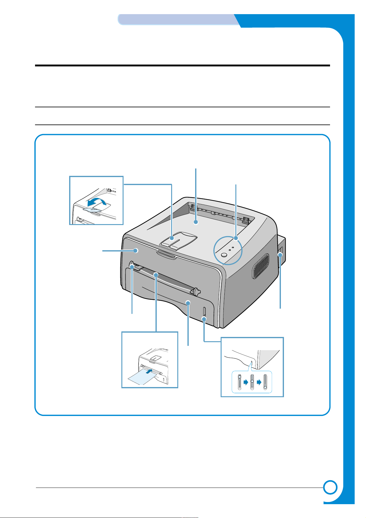
4.1.1 Front View
Output Support
Top output tray
(Face down)
Control Panel
Power switch
Paper level indicator
Tray
Manual Feeder
Manual Feeder guide
Front Cover
4-2
SUMMARY OF PRODUCT
Samsung Electronics
Service Manual
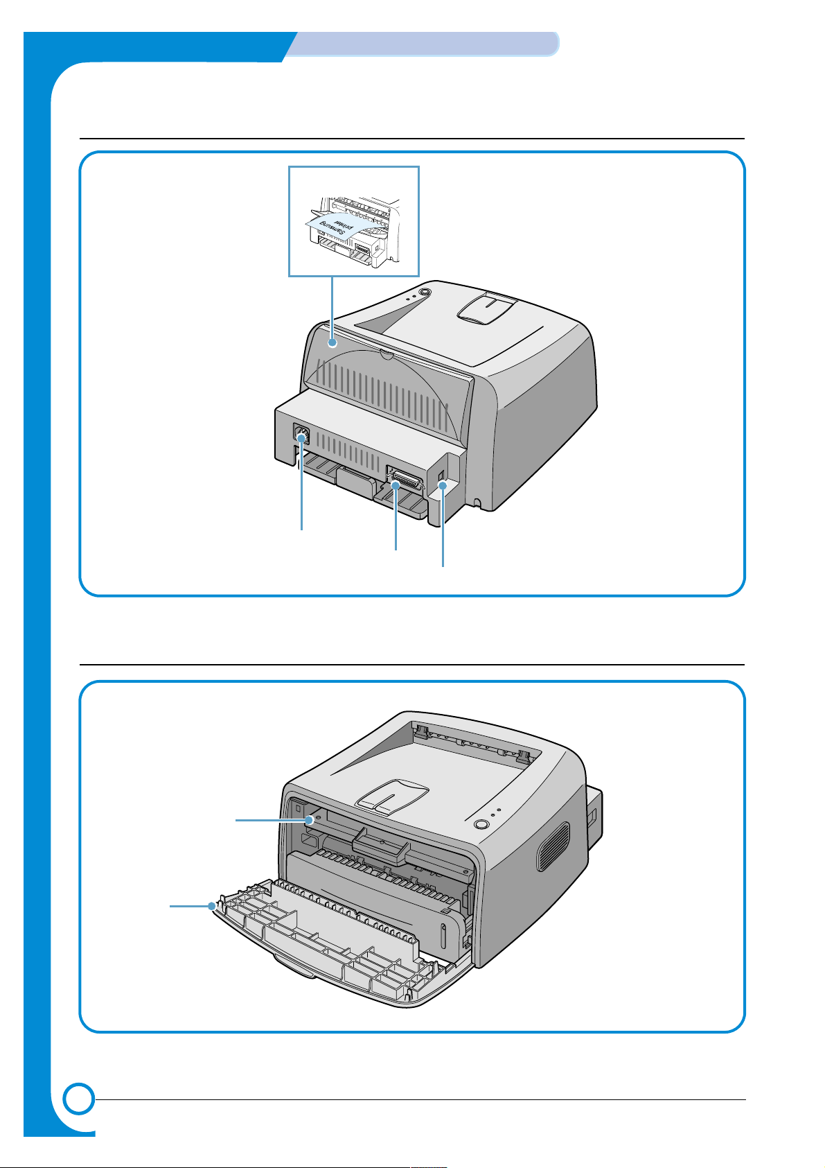
4.1.2 Rear View
Rear output tray
(Face up)
Power receptacle
Parallel port
(ML-1750 Only)
USB port
4.1.3 Inside View
Toner cartridge
Front Cover
LED Description
4-3
Samsung Electronics
SUMMARY OF PRODUCT
Service Manual
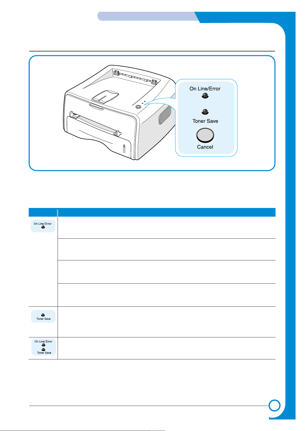
4.1.3 Control Panel
1) On Line/Error and Toner Save LEDs
If the On Line/Error lights green, the printer is ready to print.
If the On Line/Error lights red, the printer is experiencing an error, such as jammed paper,
the open cover or the empty toner cartridge. If you press the Cancel button while the printer
is receiving data, the On Line/Error LED blinks red to cancel printing.
In Manual Feed mode, if there is no paper in the Manual Feeder, the On Line/Error LED
blinks red. Load paper into the Manual Feeder and the LED stops blinking.
If the printer is receiving data, the On Line/Error LED slowly blinks green.
If the printer is printing the received data, the On Line/Error LED blinks green fast.
If you press the Cancel button in Ready mode, this LED is on and the Toner Save mode is
enabled.
If you press this button once again, this LED is off and the Toner Save mode is disabled.
If the On Line/Error and Toner Save LEDs blink, your system has some problems. To solve
the problem.

4-4
SUMMARY OF PRODUCT
Samsung Electronics
Service Manual
2) Cancel button
Printing demo page In Ready mode, press and hold this button for about 2 seconds until
all LEDs blink slowly, and release.
Printing configuration sheet In Ready mode, press and hold this button for about 6 seconds until
all LEDs blink fast, and release.
Manual feeding Press this button each time you load a sheet of paper in the manual
feeder, when you select Manual Feed for Source from your software
application.
Cleaning inside printer In Ready mode, press and hold this button for about 10 seconds
until all LEDs turn on, and release. After cleaning the printer, one
cleaning sheet prints.
Canceling print job Press this button during printing. The On Line/Error LED blinks while
the print job is cleared from both the printer and the computer, and
then return to Ready mode. This may take some time depending on
the size of the print job.
In Manual Feed mode, you can’t cancel the print job by pressing this
button.
Toner Save mode on/off In Ready mode, press this button to turn the Toner Save mode on or
off.
4-5
Samsung Electronics
SUMMARY OF PRODUCT
Service Manual
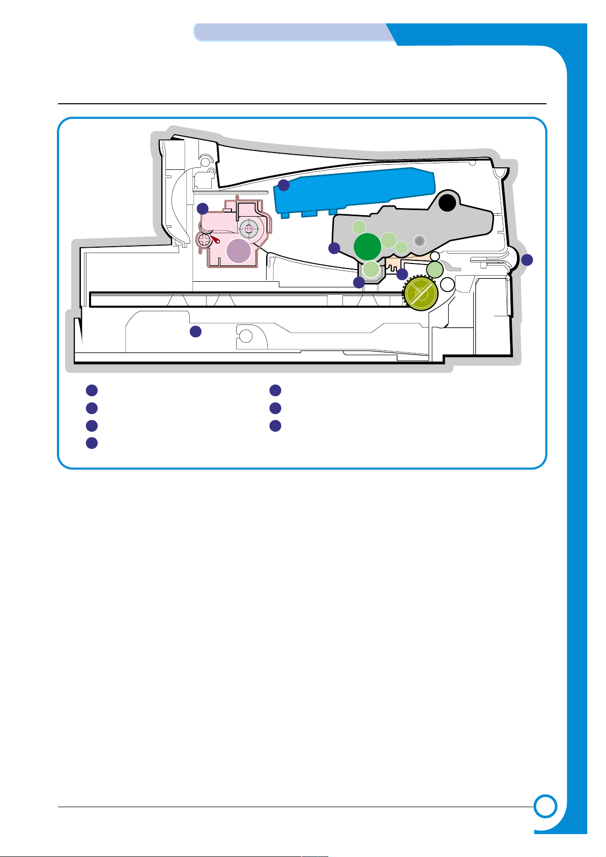
4.2 System Layout
PTL
P
I
C
K
/
R
PR
CR
DR
SR
TR FR
OPC
L S U
Fuser
Toner Cartridge
1
1
2
2
3
6
3
4
Cassette
Manual Feeder
Transfer Roller
PTL(Per-Tramsfer-Lamp)
5
7
6
7
5
Fuser
LSU(Laser Scan Unit)
Toner Cartridge
4
MP Sensor

4-6
SUMMARY OF PRODUCT
Samsung Electronics
Service Manual
4.2.1 Feeding Part
There are the universal cassette, which loads papers, and the manual feeder, which supplies paper one by
one. The cassette has the function pad which separates paper one by one, and it has the sensor function
to check the existence of the loading paper.
- Feeding Method: Universal Cassette Type
- Feeding Standard: Center Loading
- Feeding Capacity: Cassette-250 sheets (75g/m©˜, 20lb paper standard)
Manual 1 sheet (Paper, OHP, Envelop, etc.)
- Paper detecting sensor: Photo sensor
- Paper size sensor: None
4.2.2 Transfer Ass’y
It is consisted of the PTL (pre-transfer lamp) and the Transfer Roller. The PTL sends a light to the OPC
drum, makes the current on the drum surface to low, and improves the transfer efficiency.
The transfer roller delivers the toner of the OPC drum to the paper.
- The life span: Print over 60,000 sheets (in 15~30°C)
4.2.3 Driver Ass’y
It is a power delivery unit by gearing. By driving the motor, it supplies the power to the feeding unit, the
fusing unit, and the distributing unit.
4.2.4 Fixing Part(Fuser)
- The fuser is consisted of the Heat Lamp, Heat Roller, Pressure Roller, Thermistor, and Thermostat. It
adheres the toner to the paper with a pressure and a heat to complete the printing job.
- There are two methods, the existing method which use the Heat Lamp and the Q-PID which is developed
by Samsung.
110V : Heat Lamp type Fuser
220V : Heat Lamp type or Q-PID type Fuser
4.2.4.1 Temperature-Intercepting Device (Thermostat)
The thermostat is the temperature-intercepting device, which cuts off the power for preventing an overheating or a fire when the heat lamp or the heat coil of the heat roller is overheated.
4.2.4.2 Temperature Detecting Sensor (Thermistor)
The Thermistor detects the surface temperature of the heat roller, and it maintains the regular temperature
of the heat roller by responding to the information of the temperature.
4.2.4.3 Heat Roller
The heat roller transfers the temperature from the heat lamp or heat coil to the surface to heat the paper
which passes the surface. The melted toner cannot stain the heat roller coated with Teflon.
The heating elements are heat lamp and heat coil. For this product, Q-PID method with the heat coil is
applied.
4.2.4.4 Pressure roller
The pressure roller mounted right under the heat roller is made of the silicon resin, and the surface of the
roller is coated with Teflon to fuse the toner on the paper when paper passes between the heat roller and
the pressure roller.

4-7
Samsung Electronics
SUMMARY OF PRODUCT
Service Manual
4.2.4.5 Safety Relevant Facts
• Protecting device when overheating
- 1st protecting device: H/W cuts off when detecting an overheating
- 2nd protecting device: S/W cuts off when detecting an overheating
- 3rd protecting device: Thermostat cuts off the power
• Safety device
- The power of the fuser is cut off when the front cover is open.
- The overheating safety device for customer
- Maintains the surface temperature of the Fuser Cover under 80°C and attach the caution label
inside of the rear cover where customer can find easily.
4.2.5 LSU (Laser Scanner Unit)
The LSU unit is controlled by the video controller. It scans the video data received from video controller with
laser beam by using the rotation principal of the polygon mirror to create the latent image on the OPC drum.
It is the core part of LBP.
The OPC drum rotates as the same speed as the paper feeding speed. It creates the /HS YNC signal and
sends it to the engine when the laser bean of the LSU reaches the end of the polygon mirror, and the engine
detects the /HS YNC signal to arrange the vertical line of the image on the paper. After detecting the /HS
YNC signal, the image data is sent to the LSU to arrange the its left margin on the paper.
The one side of the polygon mirror is one line for scanning.
 Loading...