

Page 1

Built-in Trim Kit
Installation Instructions
MA-TK8020**
MA-TK8020_AA_II_DE68-04476A-01_EN.indd 1 2017-06-01 6:16:02
Page 2

ContentsContents
Before you begin
Before you begin 2
Read these instructions completely and carefully.
IMPORTANT
Contents
Parts included in the kits 3
Tools needed 3
Installation 4
• Save these instructions for local inspector’s use.
• Observe all governing codes and coordinates.
• Be sure to disconnect the plug of the microwave oven from the electrical outlet
before installing the Builtin Kit. Remove the turntable from the oven cavity.
• The kit includes metal parts, due caution should be used in handling and
installation to avoid the possibility of injury.
• Do not remove permanently afxed labels, warnings or plates from the
product. Doing so may void the warranty.
WARNING
The electrical requirements for this oven are 115-120 volts AC, 15 amps or larger.
2 English
MA-TK8020_AA_II_DE68-04476A-01_EN.indd 2 2017-06-01 6:16:02
Page 3
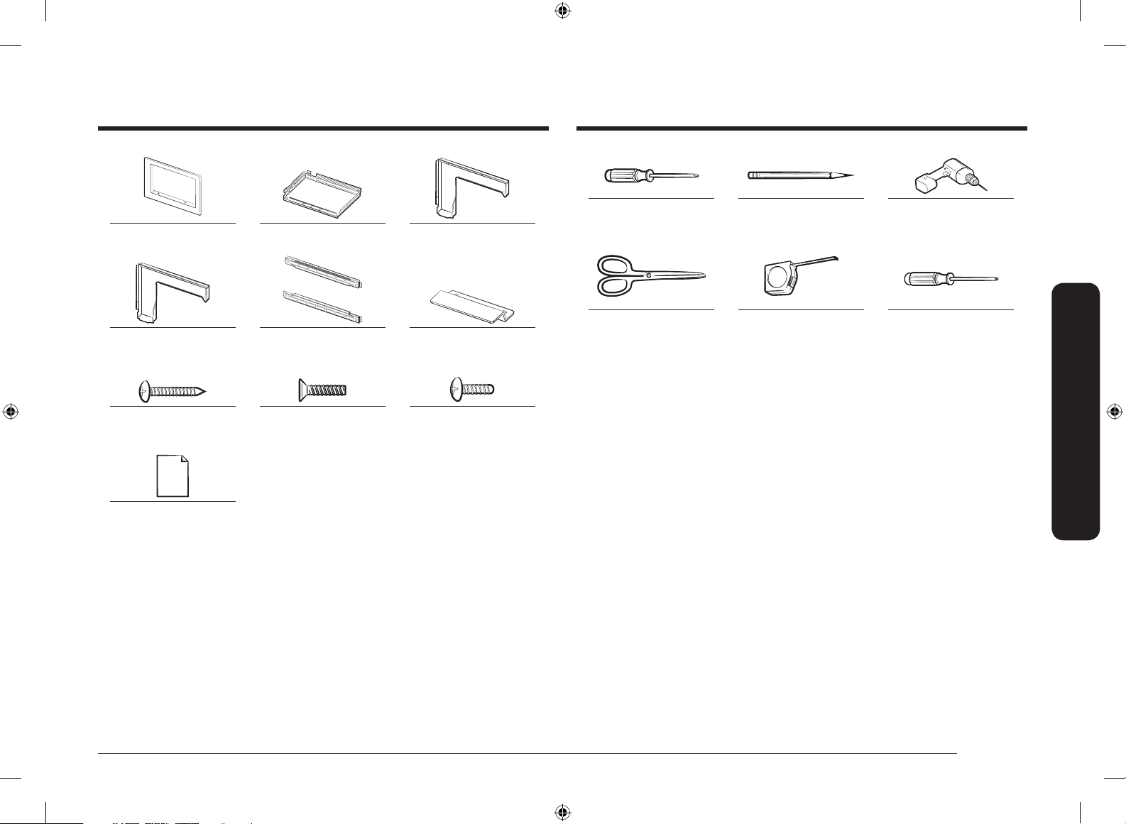
Parts included in the kits
Trim Frame (1 EA) Duct Base (1 EA) Duct Side (1 EA)
Tools needed
Screwdriver Pencil Drill with 7/64 or #35 Drill
bit
Duct Rear (1 EA) Install Bracket (2 EA)
Screw A
(5/8” length) (12 EA)
Template (1 EA)
Screw B
(15/32” length) (4 EA)
Install hook
Screw C
(25/64” length) (9 EA)
Scissors Tape measure
T15H Torx driver
Parts included in the kits
English 3
MA-TK8020_AA_II_DE68-04476A-01_EN.indd 3 2017-06-01 6:16:03
Page 4
Installation
Installation
Installation
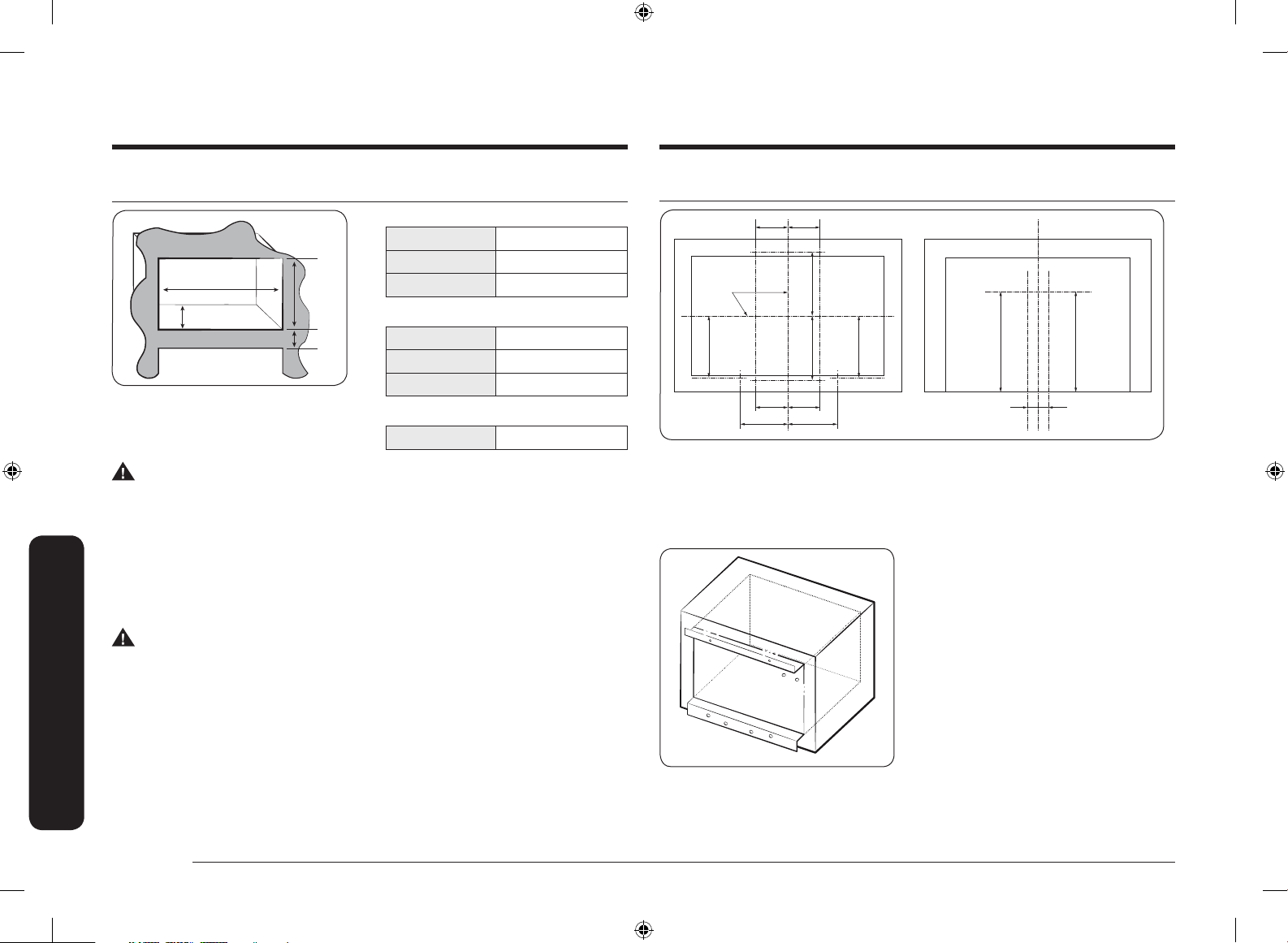
STEP 1
CUTOUT DIMENSIONS
Height 16 3/4" ± 1/16"
Width 25 1/2" ± 1/16"
Width
Depth
3" min
Electric Heat
Source Model
WARNING
To avoid risk of electrical shock, personal injury, or death:
• Before drilling into the wall, note where electrical outlets are and where
electrical wire might be concealed behind the wall. YOU COULD GET AN
ELECTRICAL SHOCK if you contact electrical wire with the drill bit.
• Locate and disconnect the power to any electrical circuits that could be
affected by installing this oven.
IF YOU DO NOT DISCONNECT THE POWER, YOU COULD GET AN ELECTRICAL SHOCK.
WARNING
To avoid personal injury, wear gloves when handling the metal parts. Parts are
sharp and can cause cuts and abrasions.
Height
Depth 21 1/2" ± 1/16"
TRIM DIMENSIONS
Height 20 1/16" ± 1/64"
Width 29 3/4" ± 1/64"
Depth 1 1/4" ± 1/64"
TRIM WEIGHT
Net Weight 13.23 lb
STEP 2
A
P5
CENTER
LINE
D D
A
P2
B B
P1
A : 5 1/8" (130 mm)
B : 6 7/8" (175 mm)
C : 9 3/8" (238.5 mm)
D : 8 23/32" (221.3 mm)
P5
P6
P7
P8
P1
P2
P3
P4
A
P6
C
C
A
P3
P4
1. Folding the underline of Template
2. Folding the topline of Template and
3. Then drill a pilot hole at the
F F
E : 7/8" (23 mm)
F : 16 1/8" (409.5 mm)
and match with the cabinet edge
line, mark 6holes at bottom.
(P1,2,3,4,7,8)
match with the cabinet edge line,
mark 2holes at top. (P5,6)
8positions using 7/64 or #35 drill
bit.
P8P7
EE
4 English
MA-TK8020_AA_II_DE68-04476A-01_EN.indd 4 2017-06-01 6:16:04
Page 5
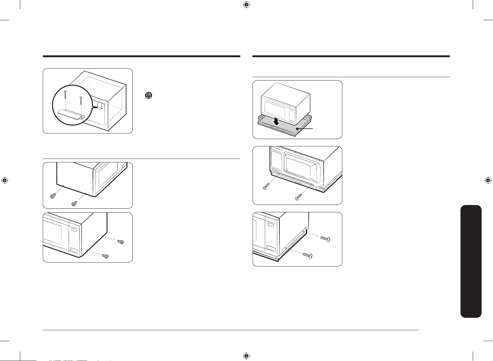
4. Tight 2 screws together on the
Install hook by using provided
SCREW A. (2 EA)
NOTE
You may not be assembled when using
the thicker Drill bit.
STEP 4
1. Place oven on the Duct Base.
Duct Base
STEP 3
5. Remove 4 screws from the lower
right and left side of outer panel.
2. Tight 2 screws together on the
back side with Duct base by using
provided SCREW C. (2 EA)
3. Tight 2 screws together on the
right side with Duct base by using
provided SCREW C. (2 EA)
Installation
English 5
MA-TK8020_AA_II_DE68-04476A-01_EN.indd 5 2017-06-01 6:16:04
Page 6

Installation
Installation
Torx screw
Duct Rear
Duct Side
4. Tight 4 screws to Duct base and
Duct side on the left side by using
provided SCREW C. (4 EA)
5. Remove 2 Screw C on top of the
back. In addition, Remove 1 Torx
Screw to use Torx driver on bottom
of the back. Do not scrap Screw.
(3 EA)
6. Tight a Torx Screw and 3 Screw C
on top of the back.
STEP 5
Check the assembly
between Install hook
and Duct base.
1. Slide the oven with Duct Base into
cabinet until Duct Base touch the
front of cabinet.
2. Plug the Power cord into the
electrical outlet.
3. Tight 2 screws to Duct base and
Cabinet by using provided SCREW
A. (2 EA)
NOTE
Be aware when you put a oven into the
cabinet because cabinet may be moved.
Align the Center with cabinet
4. After placing the Install Bracket to
match with holes, tight together by
using provided SCREW A. (4 EA)
Torx screw
6 English
MA-TK8020_AA_II_DE68-04476A-01_EN.indd 6 2017-06-01 6:16:04
Install
Bracket
Page 7

STEP 6
5. Tight Install Bracket 4 holes by
using provided SCREW A. (4 EA)
1. Press the Trim Frame into the
opening until all sides snap into
place.
Top
2. Open the oven door. Tight 4 screws
Trim frame by using provided
SCREW B. (4 EA)
Trim Frame
MA-TK8020_AA_II_DE68-04476A-01_EN.indd 7 2017-06-01 6:16:05
Bottom
English 7
Installation
Page 8

DE68-04476A-01
MA-TK8020_AA_II_DE68-04476A-01_EN.indd 8 2017-06-01 6:16:05
Page 9

Kit de marco embellecedor para empotrar
Instrucciones de instalación
MA-TK8020**
MA-TK8020_AA_II_DE68-04476A-01_MES.indd 1 2017-06-01 6:15:46
Page 10

ContenidoContenido
ANTES DE COMENZAR
Contenido
ANTES DE COMENZAR 2
Piezas incluidas en los kits 3
Herramientas necesarias 3
Instalación 4
Lea estas instrucciones con detenimiento en su totalidad.
IMPORTANTE
• Conserve estas instrucciones para que puedan ser consultadas por el inspector
de su localidad.
• Cumpla todos los códigos y coordenadas exigidos por las autoridades
pertinentes.
• Asegúrese de desconectar el enchufe del horno de microondas del
tomacorriente antes de instalar el kit para empotrar. Retire el plato giratorio de
la cavidad del horno.
• El kit incluye piezas metálicas, por lo que debe tener cuidado durante el
manejo y la instalación para evitar el riesgo de lesiones.
• No elimine del producto ninguna etiqueta, advertencia o placa adherida
permanentemente. Hacerlo puede anular la garantía.
ADVERTENCIA
Los requisitos eléctricos para este horno son 115-120 voltios CA, 15 amperios o
superior.
2 Español
MA-TK8020_AA_II_DE68-04476A-01_MES.indd 2 2017-06-01 6:15:46
Page 11

Piezas incluidas en los kits
Marco embellecedor
(1 ud.)
Conducto base (1 ud.) Conducto lateral (1 ud.)
Herramientas necesarias
Destornillador Lápiz Perfore con mecha de 7/64
o #35.
Conducto posterior (1 ud.) Ménsula de instalación
(2 uds.)
Tornillo A
(5/8” largo) (12 uds.)
Plantilla (1 ud.)
Tornillo B
(15/32” largo) (4 uds.)
Gancho de instalación
Tornillo C
(25/64” largo) (9 uds.)
Tijeras Cinta de Medir
Destornillador Torx T15H
Piezas incluidas en los kits
Español 3
MA-TK8020_AA_II_DE68-04476A-01_MES.indd 3 2017-06-01 6:15:47
Page 12

Instalación
Instalación
Instalación
STEP 1
DIMENSIONES DE LA ABERTURA
RECORTADA
Altura 16 3/4" ± 1/16"
Ancho
Profundidad
3” mín.
Modelo con fuente
de calor eléctrica
ADVERTENCIA
Para evitar el riesgo de descargas eléctricas, lesiones personales o la muerte:
• Antes de perforar la pared, observe dónde están los tomacorrientes y donde
podría estar el cable eléctrico oculto detrás de la pared. PODRÍA RECIBIR UNA
DESCARGA ELÉCTRICA si toca el cable eléctrico con la mecha.
• Ubique y desconecte la alimentación de cualquier circuito eléctrico que podría
verse afectado por la instalación de este horno.
SI NO DESCONECTA LA ALIMENTACIÓN, PODRÍA RECIBIR UNA DESCARGA
ELÉCTRICA.
ADVERTENCIA
Para evitar una lesión física, use guantes cuando manipule las piezas metálicas. Las
piezas son aladas y pueden causar cortes y abrasiones.
Altura
Ancho 25 1/2" ± 1/16"
Profundidad 21 1/2" ± 1/16"
DIMENSIONES DEL BORDE
Altura 20 1/16" ± 1/64"
Ancho 29 3/4" ± 1/64"
Profundidad 1 1/4" ± 1/64"
PESO DEL BORDE
Peso neto 13.23 lb
PASO 2
A
P5
LÍNEA CENTRAL
D D
A
P2
B B
P1
A : 5 1/8" (130 mm)
B : 6 7/8" (175 mm)
C : 9 3/8" (238.5 mm)
D : 8 23/32" (221.3 mm)
P5
P6
P7
P8
P1
P2
P3
P4
A
P6
C
C
A
P3
P4
1. Pliegue la línea inferior de la
2. Pliegue la línea superior de la
3. Luego perfore un agujero piloto en
F F
E : 7/8" (23 mm)
F : 16 1/8" (409.5 mm)
plantilla de modo que coincida
con la línea del borde del gabinete
y marque 6 agujeros en la parte
inferior. (P1,2,3,4,7,8)
plantilla de modo que coincida
con la línea del borde del gabinete
y marque 2 agujeros en la parte
superior. (P5,6)
las ocho posiciones con una mecha
de 7/64 o #35.
P8P7
EE
4 Español
MA-TK8020_AA_II_DE68-04476A-01_MES.indd 4 2017-06-01 6:15:47
Page 13

4. Ajuste 2 tornillos en el gancho de
instalación; use los TORNILLOS A
(2 uds.) provistos.
NOTA
Si la mecha es más gruesa, es posible
que no pueda instalarlo.
PASO 4
1. Coloque el horno en el conducto
base.
Conducto
base
PASO 3
5. Quite 4 tornillos del lado inferior
derecho e izquierdo del panel
exterior.
2. Ajuste 2 tornillos en el lado trasero
con el conducto base; use los
TORNILLOS C (2 uds.) provistos.
3. Ajuste 2 tornillos en el lado derecho
con el conducto base; use los
TORNILLOS C (2 uds.) provistos.
Instalación
Español 5
MA-TK8020_AA_II_DE68-04476A-01_MES.indd 5 2017-06-01 6:15:47
Page 14

Instalación
Instalación
Tornillo Torx
Conducto
posterior
Tornillo Torx
Conducto
lateral
4. Ajuste 4 tornillos en el conducto
base y el conducto lateral por el
lado izquierdo; use los TORNILLOS C
(4 uds.) provistos.
5. Quite 2 tornillos C de la parte
superior trasera. Además, quite 1
tornillo Torx con el destornillador
Torx de la parte inferior trasera. No
deseche los tornillos (3 uds.).
6. Ajuste un tornillo Torx y 3 tornillos
C en la parte superior trasera.
PASO 5
Verique el conjunto entre
el gancho de instalación y el
conducto base.
1. Deslice el horno con el conducto
base hasta el gabinete hasta que el
conducto base toque el frente del
gabinete.
2. Enchufe el cable de alimentación en
el tomacorriente.
3. Ajuste 2 tornillos en el conducto
base y el gabinete; use los
TORNILLOS A (2 uds.) provistos.
NOTA
Tenga cuidado cuando coloque el
horno en el gabinete ya que este puede
moverse.
Alinee el centro con el gabinete.
4. Después de colocar la ménsula de
instalación de modo que coincida
con los agujeros, ajuste ambos
mediante los TORNILLOS A (4 uds.)
provistos.
Ménsula de
instalación
6 Español
MA-TK8020_AA_II_DE68-04476A-01_MES.indd 6 2017-06-01 6:15:48
Page 15

STEP 6
5. Ajuste los 4 agujeros de la ménsula
de instalación; use los TORNILLOS A
(4 uds.) provistos.
1. Presione el marco embellecedor
en la abertura hasta que los lados
encajen en su lugar.
Superior
2. Abra la puerta del horno. Ajuste los
4 tornillos del marco embellecedor;
use los TORNILLOS B (4 uds.)
provistos.
Marco embellecedor
MA-TK8020_AA_II_DE68-04476A-01_MES.indd 7 2017-06-01 6:15:48
Inferior
Español 7
Instalación
Page 16

DE68-04476A-01
MA-TK8020_AA_II_DE68-04476A-01_MES.indd 8 2017-06-01 6:15:48
 Loading...