

Samsung lt 17n23w service manual
TFT-LCD TV/MONITOR
Chassis Model
VR17JO LT17N23W
SERVICE
Manual
TFT-LCD TV/MONITOR CONTENTS
1. Precautions
2. Product Specifications
3. Disassembly & Reassembly
4. Alignment & Adjustments
5. Troubleshooting
6. Exploded View & Parts List
7. Parts List
8. Block Diagram
9. Wiring Diagram
10. PCB Layout
11. Schematic Diagrams
12. Panel Description
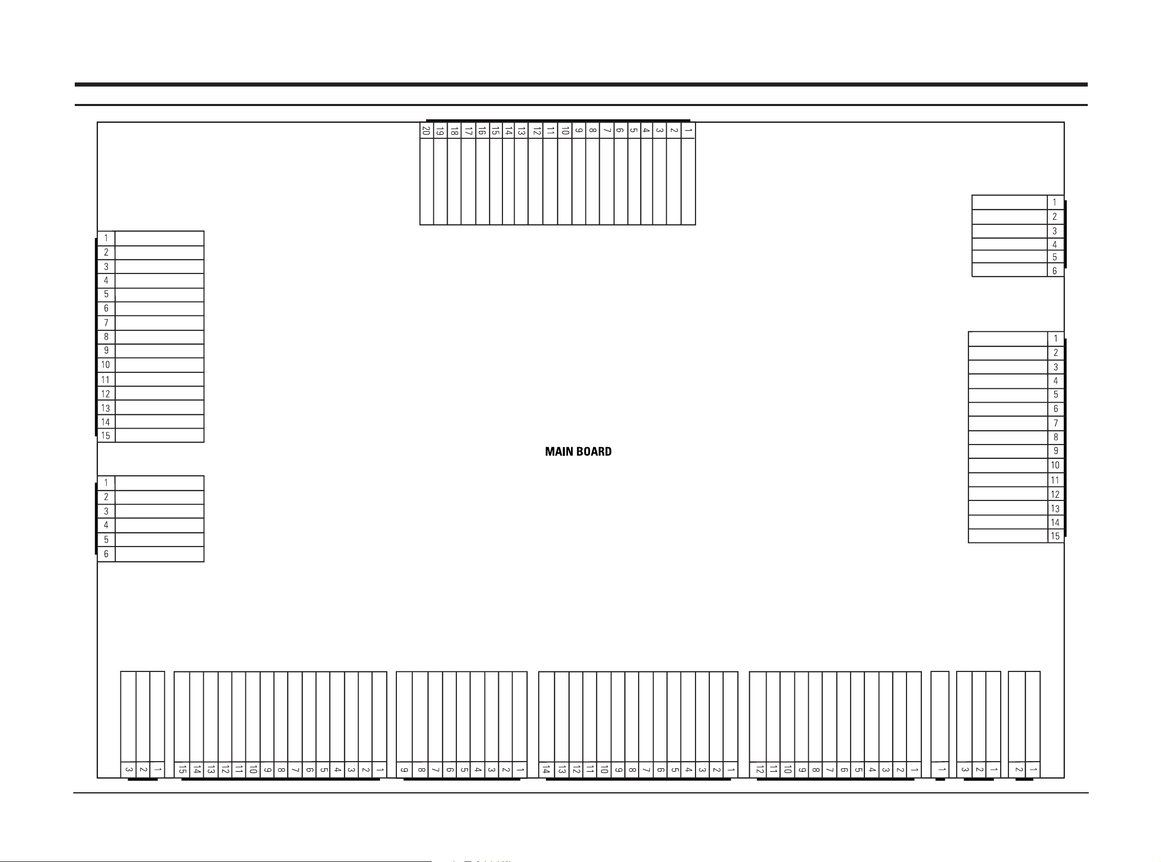
LT17N23W 9-1
NC
NC
NC
NC
TXOUT3+
TXOUT3-
GND
GND
TXOUT2+
TXOUT2-
TXOUT1+
TXOUT1-
TXOUT0+
TXOUT0-
GND
GND
TXOUT3+
TXOUT3-
TXCLKOUT+
TXCLKOUT-
GND
ADJ_BRIGHTNESS
GND
AGASW_INVERTER
GND
GND
NC
GND
GND
14_INVERTER
14_INVERTER
14_INVERTER
14_INVERTER
14_INVERTER
14_INVERTER
LED_GRN
LED RED
NC
A3.3V
IR
GND
GND
COMP1_CR
NC
GND
COMP1_CB
NC
GND
COMP1_Y
NC
14V_INVERTER
GND
14V_INVERTER
NC
GND
COMP1_L
GND
D4_L
GND
NC
GND
COMP1_R
GND
D4_R
GND
PC_RED
PC_GREEN
PC_BLUE
GND
GND
GND
GND
GND
PC_5V
IDENT_PC
GND
DDC_TXO
H_SYNC
DDC_RXO
V_SYNC
CN804
CN805
KEY1
POWER_KEY
CH+_OUT
CH-_OUT
NC
GND
CN806
CN505
CN807
CN802 CN803CN601
TUNER
CN809
SPKOUTR+
NC
SPKOUTR-
CN702
SPKOUTL+
SPKOUTL-
CN701CN808
D4_Y
GND
D4_PB
GND
D4_PR
GND
NC
D4_L1
D4_L2
NC
D4_L3
GND
NC
D4_ID
CN801
GND
IDENT_HP
GND
HP_L
HP_R
GND
PC_AUDIO_L
PC_AUDIO_R
GND
SVHS_C
SVHS_Y
VIDEO_CVBS
GND
VIDEO_L
VIDEO_R
9 Wiring Diagram
LT17N23W 5-1
5 Troubleshooting
5-1 No Power
Does proper DC 14V at C602?
Check adapter for 14V and 4.5A.
Yes
No
Does proper DC 5V
appear at L601?
Change IC601 or main ass’y.
(BN91-00716A)
Yes
No
Does each proper DC1.8V, 3.3V
appear at L604, L605?
Change IC610 or main ass’y.
(BN91-00716A)
Yes
No
Does each proper DC 5V
appear at L603?
Change IC602 or main ass’y.
(BN91-00716A)
Yes
No
Does each proper DC 3.3V, 33V
appear at C618, C621?
Change IC603/IC604 or
main ass’y. (BN91-00716A)
Yes
No
Does proper DC 14V
appear at C628?
Change IC605 or main ass’y.
(BN91-00716A)
Yes
No
Does each proper DC 8V, 9V_1
appear at C635, C638?
Check IC607/IC608 and
related circuit.
Yes
No
Replace the board with new one.
1-1
1-2
1-3
1-4
1-5
1-6
1-7
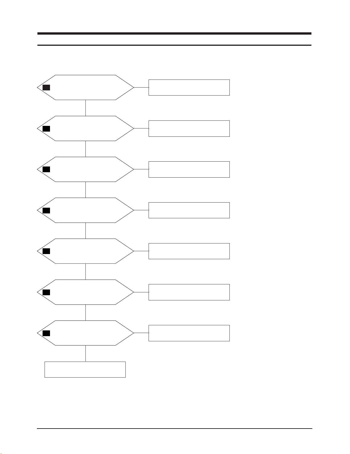
5 Troubleshooting
5-2 LT17N23W
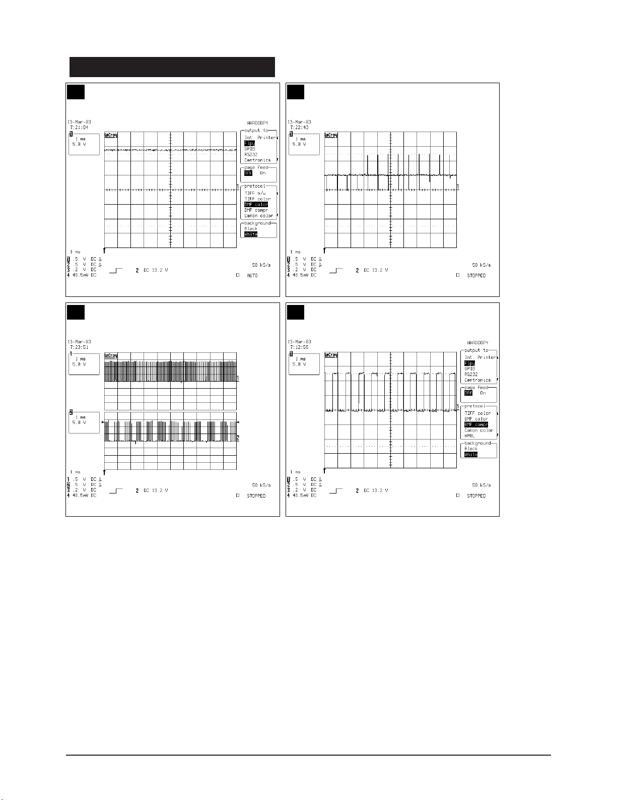
WAVEFORMS
1-1 1-2
1-3 1-4
WAVEFORMS
1-5 1-6
1-7
5 Troubleshooting
LT17N23W 5-3
5 Troubleshooting
5-4 LT17N23W
5-2 No PC Signal
Does the signal R, G, B,
H, V appear at C122/C119/
C124/C164/C165?
Check IC102 or D-SUB signal cable.
Yes
No
Does the signal appear at
RA101~RA107?
Change IC101 or main ass’y.
(BN91-00716A)
A
Yes
No
Does the signal appear at
RA514~RA519?
Change main ass’y.
(BN91-00716A)
Yes
No
Does the signal appear at X501?
Change X501 or main ass’y.
(BN91-00716A)
Yes
No
Yes
Power indicator is green.
Replace the LCD_panel
with new one.
2-1
2-2
2-3
2-4
2-5
5 Troubleshooting
LT17N23W 5-5
WAVEFORMS
2-1 2-2
2-3
2-5
2-4
5 Troubleshooting
5-6 LT17N23W
5-3-1 No Video (Tuner, AV CVBS, S-Video)
Does the signal appear at
C237 (TV), C230 (AV),
C229 (SVHS_Y), C228 (SVHS_C)
Change CN809 or replace
SUB_board with new one.
Yes
No
Does the signal appear at
RA201~RA204?
Change IC305 or replace main board
with new one.
Yes
No
Does the signal appear at X201?
Change X201 or replace main
board with new one.
Yes
No
3-1
3-3
3-2
3-4
3-5
5-3-2 No Video (Component 1, D Connector Input [408i, 480p, 720p, 1080i])
Does the signal appear at
C136, C137, C140 (Y, Pb, Pr)?
Change IC103, CN802 or replace
main board with new one.
Yes
No
3-7
3-9
3-8
3-6
Repeat ‘A’ process.
Repeat ‘A’ process.
 Loading...