

Samsung LH85QBREBGCXEN User Manual

Smart Signage User Manual (By Model)
This manual provides information about your Smart Signage including supported types and product specications per model.
QBR (QB43R QB49R QB50R QB55R QB65R QB75R QB85R QB98R)
QER (QE82R)
QMR (QM32R QM43R QM49R QM50R QM55R QM65R QM75R QM85R)
QMR-T (QM32R-T QM43R-T QM55R-T)
The colour and the appearance may differ depending on the product, and the content in the
manual is subject to change without prior notice to improve the performance.
Recommended hours of use per day for the QBR models (except for QB98R), QM32R, and QER
models is less than 16 hours.
If the product is used for longer than 16 hours a day, the warranty may be void.
An administration fee may be charged in the following situations:
(a) An engineer is called out at your request, but it is found that the product has no defect (i.e.,
where the user manual has not been read).
(b) You bring the unit to a repair centre, but it is found that the product has no defect (i.e.,
where the user manual has not been read).
You will be informed of the administration fee amount before a technician visits.
© Samsung
Samsung owns the copyright for this manual. Use or reproduction of this manual in parts or entirety without the authorization of Samsung is prohibited. Trademarks other than Samsung are property of their respective owners.

Table of contents
Preparations
Checking the Components 3
Parts 4
QM32R/Q*43R/Q*49R/Q*50R/Q*55R/
Q*65R/Q*75R/Q*85R/QE82R/QM32R-T/
QM43R-T/QM55R-T
QB98R
5
Anti-theft Lock 6
Ports 7
Q*43R/Q*49R/Q*50R/Q*55R/Q*65R/
Q*75R/Q*85R/QE82R
QM32R
8
QB98R
9
QM32R-T
QM43R-T/QM55R-T
Control menu 12
Administrator menu (Supported models:
QMR-T
Precautions when handling the panel 14
Before Installing the Product (Installation
Guide) 15
Tilting Angle and Rotation 15
Ventilation 15
10
) 13
4
7
11
Using a touchscreen monitor
(Supported models: QMR-T)
Touchscreen monitor 18
Read below before using the product 18
Connecting the touch overlay 18
Connecting the touchscreen monitor 19
Connecting to a PC 19
Connecting to a laptop or tablet PC 19
Configuring the touchscreen monitor
settings 20
Calibration 20
Specifications
General 22
Preset Timing Modes 24
Appendix
Licence 25
Installing the Wall Mount 16
Preparing before installing Wall-Mount 16
Installing the Wall Mount 16
Wall Mount Kit Specifications (VESA) 17
2
Chapter 01
Preparations
Contact the vendor where you
"
purchased the product if any
components are missing.
The appearance of the components
"
may differ from the images shown.
A stand is not provided with the
"
product. To install a stand, you can
purchase one separately.
The RS232C adapter can be used to
"
connect to another monitor using the
D-SUB (9-pin) type RS232C cable.
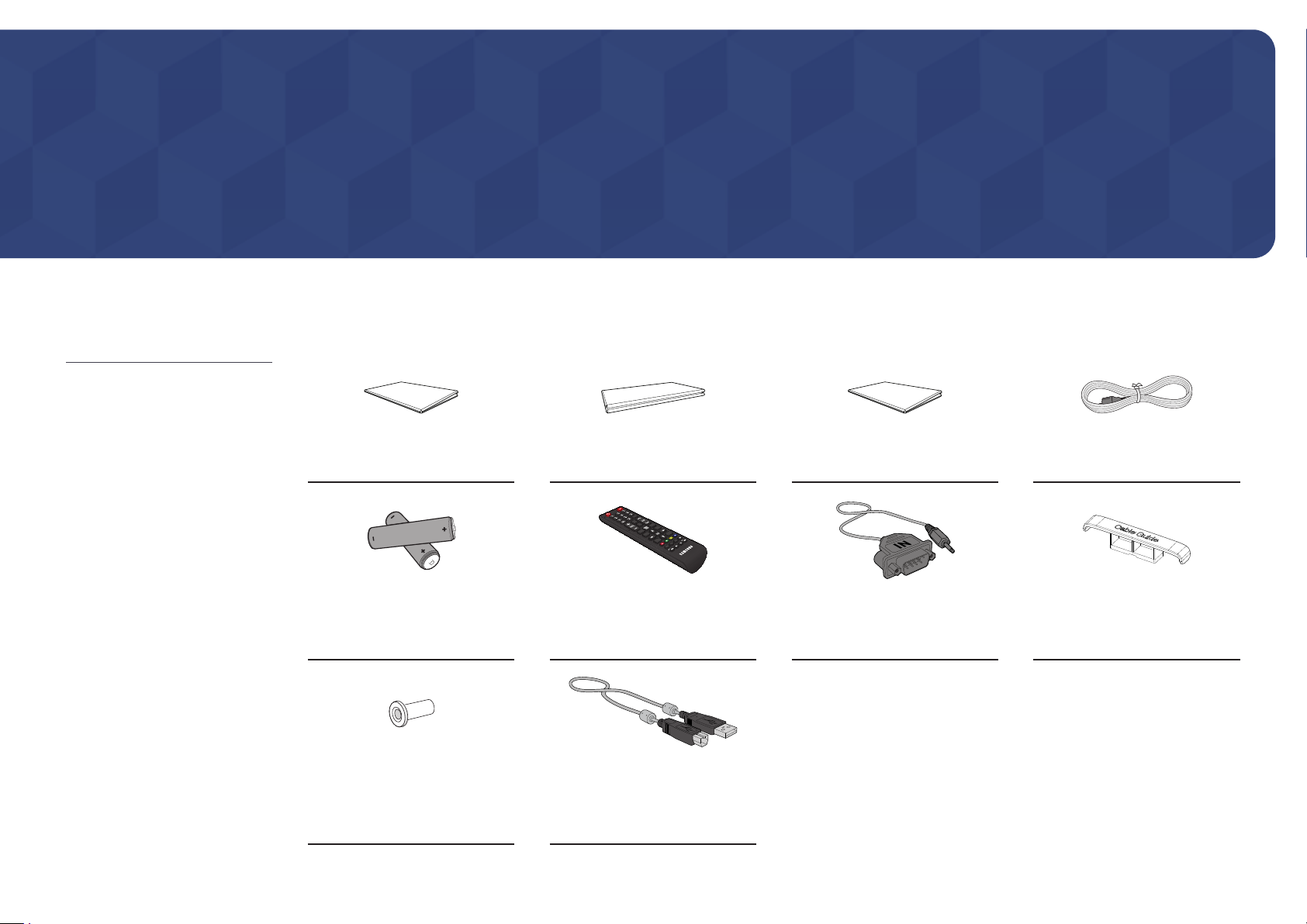
Checking the Components
Quick Setup Guide
Batteries (AAA x 2)
(Not available in some locations)
(Not available in some locations)
Warranty card
Remote Control RS232C adapter
Regulatory guide Power cord
HOLDER-CABLE
(Supported models: Q*65R,
Q*75R, Q*85R, QB98R, QE82R)
Holder-Ring x 4
(Supported models: Q*43R,
Q*49R, Q*50R, Q*55R, Q*65R,
Q*75R, QM43R-T, QM55R-T)
TOUCH OUT cable x 2
(Supported models: QMR-T)
3

Parts
"
The colour and shape of parts may differ from what is shown. Specifications are subject to change without
notice to improve quality.
Parts Description
QM32R/Q*43R/Q*49R/Q*50R/Q*55R/ Q*65R/Q*75R/Q*85R/QE82R/QM32R-T/ QM43R-T/QM55R-T
Remote sensor
30°
4 m
30°
2.5 m
2.5 m
Power button
Power indicator
Press a button on the remote control pointing at the sensor on the front of the product
Remote sensor
Power button
Use the remote control within 2.5 m to 4 m from the sensor on the product at an angle of 30° from the left and
right.
"
To enhance the IR receiver performance, connect an external IR cable (sold separately) to the IR IN port.
to perform the corresponding function.
"
Using other display devices in the same space as the remote control of this product
can cause the other display devices to be inadvertently controlled.
Turns the product on or off.
Speaker
4
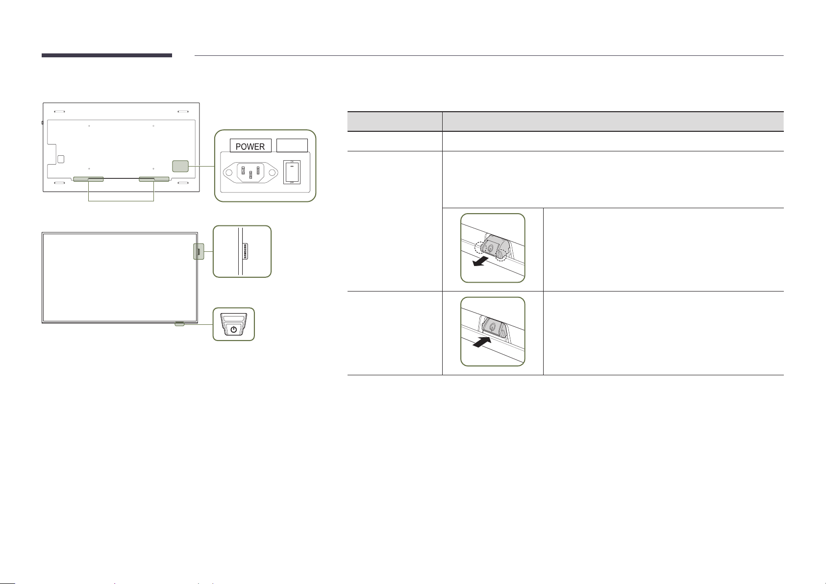
QB98R
"
The colour and shape of parts may differ from what is shown. Specifications are subject to change without
notice to improve quality.
Parts Description
Speaker
ON/OFF
Spacer logo
Remote sensor & Power button
Spacer logo
Remote sensor
Power button
Use the remote control within 7 m to 10 m from the sensor on the product at an angle of 30° from the left and right.
"
To enhance the IR receiver performance, connect an external IR cable (sold separately) to the IR IN port.
Do not pull on the spacer logo using force. The logo may tear or break off.
Press a button on the remote control pointing at the bottom of the product face to
perform the function. The remote control sensor is located on the bottom of the product.
"
Using other display devices in the same space as the remote control of this product
can cause the other display devices to be inadvertently controlled.
To use remote/eco sensor, make sure the sliding power button
is protruding from the bottom of the product.
To use the power button, make sure the sliding power button
is not protruding from the bottom of the product.
5

Anti-theft Lock
"
An anti-theft lock allows you to use the product securely even in public places.
"
The locking device shape and locking method depend on the manufacturer. Refer to the user guide provided with your anti-theft locking device for details.
"
The following images are for reference only. Real-life situations may differ from what is shown in the images.
"
Supported model: QB98R
To lock an anti-theft locking device:
Fix the cable of your anti-theft locking device to a heavy object such as a desk.
1
Put one end of the cable through the loop on the other end.
2
Insert the locking device into the anti-theft lock slot at the back of the product.
3
Lock the locking device.
4
– An anti-theft locking device can be purchased separately.
– Refer to the user guide provided with your anti-theft locking device for details.
– Anti-theft locking devices can be purchased at electronics retailers or online.
6
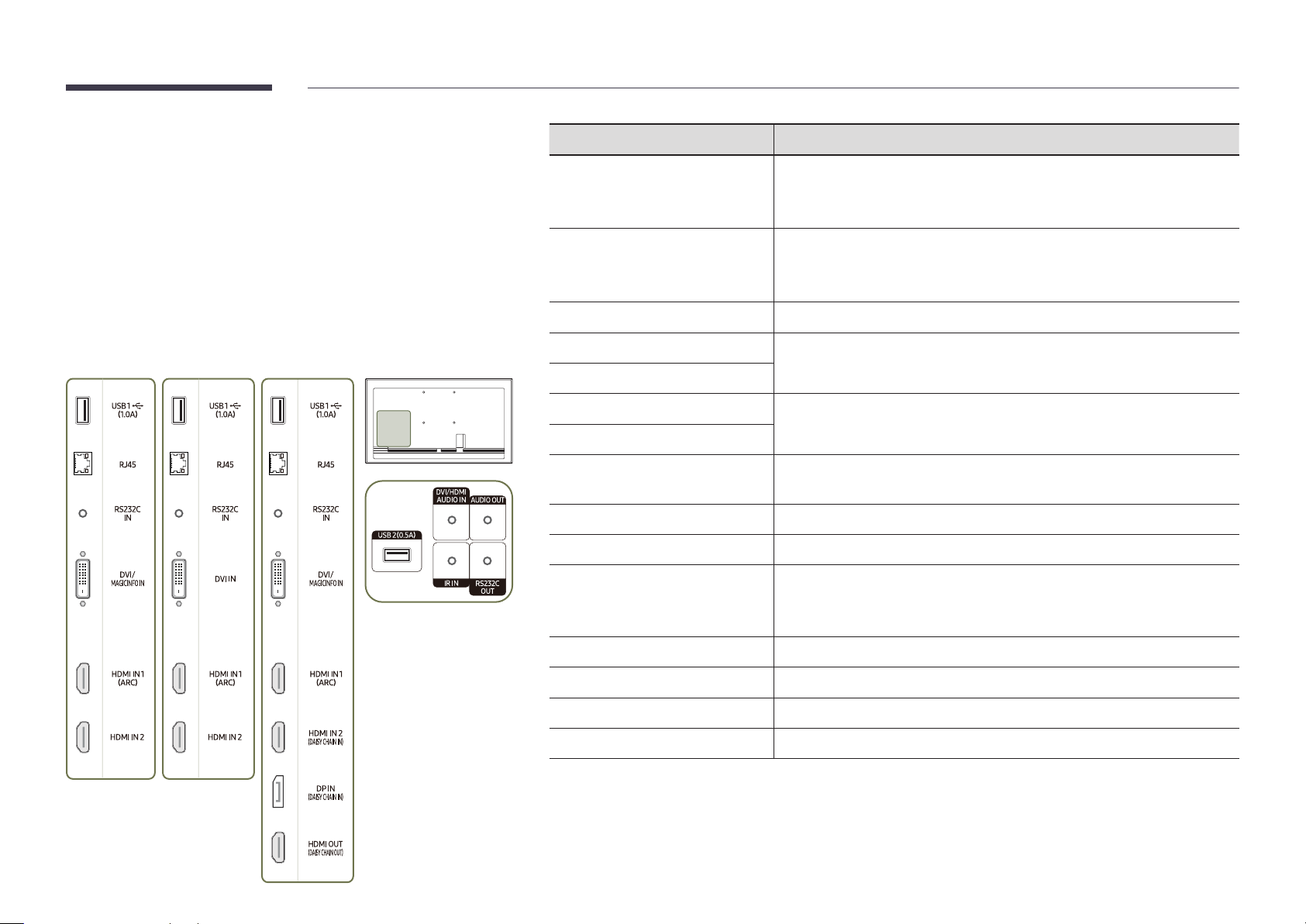
Ports
QM43R / QM49R / QM50R /
QE82R
QB43R / QB49R / QB50R /
Q*43R/Q*49R/Q*50R/Q*55R/Q*65R/ Q*75R/Q*85R/QE82R
"
QB55R / QB65R / QB75R /
QB85R
The colour and shape of parts may differ from what is shown.
Specifications are subject to change without notice to improve quality.
QM55R / QM65R / QM75R /
QM85R
Port Description
USB 1 ¨(1.0A)
RJ45
RS232C IN
DVI/MAGICINFO IN
DVI IN
Connect to a USB memory device.
"
The USB ports on the product accept a maximum constant current of 1.0A.
If the maximum value is exceeded, USB ports may not work.
Connects to MDC and the Internet using a LAN cable. (10/100 Mbps)
"
Use Cat7(*STP Type) cable for the connection.
*Shielded Twist Pair.
Connects to MDC using an RS232C adapter.
DVI IN: Connects to a source device using a DVI cable or HDMI-DVI cable.
MAGICINFO IN: Connects to a network box using DP-DVI cable to use Magicinfo.
HDMI IN 1 (ARC)
HDMI IN 2
HDMI IN 2 (DAISY CHAIN IN)
DP IN (DAISY CHAIN IN)
HDMI OUT (DAISY CHAIN OUT)
USB 2(0.5A)
DVI/HDMI AUDIO IN
AUDIO OUT
IR IN
RS232C OUT
Connects to a source device using a HDMI cable or HDMI-DVI cable.
• Connects to a source device using a HDMI cable or HDMI-DVI cable.
• Connects to another product using a HDMI cable.
Connects to a PC using a DP cable.
Connects to another product using a HDMI cable.
Connect to a USB memory device.
"
The USB ports on the product accept a maximum constant current of
0.5A. If the maximum value is exceeded, USB ports may not work.
Receives sound from a source device via an audio cable.
Outputs sound to an audio device via an audio cable.
Connects to an external IR cable that receives signals from the remote control.
Connects to MDC using an RS232C adapter.
7

QM32R
Port Description
"
The colour and shape of parts may differ from what is shown.
Specifications are subject to change without notice to improve quality.
USB 1 ¨(1.0A)
HDMI IN 1 (ARC)
RJ45
RS232C IN
HDMI IN 2 (DAISY CHAIN IN)
DP IN (DAISY CHAIN IN)
HDMI OUT (DAISY CHAIN OUT)
USB 2(0.5A)
AUDIO OUT
IR IN
Connect to a USB memory device.
"
The USB ports on the product accept a maximum constant current of 1.0A.
If the maximum value is exceeded, USB ports may not work.
Connects to a source device using a HDMI cable or HDMI-DVI cable.
Connects to MDC and the Internet using a LAN cable. (10/100 Mbps)
"
Use Cat7(*STP Type) cable for the connection.
*Shielded Twist Pair.
Connects to MDC using an RS232C adapter.
• Connects to a source device using a HDMI cable or HDMI-DVI cable.
• Connects to another product using a HDMI cable.
Connects to a PC using a DP cable.
Connects to another product using a HDMI cable.
Connect to a USB memory device.
"
The USB ports on the product accept a maximum constant current of
0.5A. If the maximum value is exceeded, USB ports may not work.
Outputs sound to an audio device via an audio cable.
Connects to an external IR cable that receives signals from the remote control.
RS232C OUT
Connects to MDC using an RS232C adapter.
8
 Loading...