How it Works
Log In / Sign Up
Buy Points
How it Works
FAQ
Contact Us
Questions and Suggestions
Users
Samsung
Loading...
L
LH008IWJ
2
LH008IWJMWS/EN
LH008IWJMWS/ZA
LH008IWJ Series
LH008IWR
LH008IWRMWS/EN
LH012IFJ
LH012IWJ
2
LH015IFH SERIES
LH015I SERIES
LH016IWJ
2
LH020IFH SERIES
LH020I SERIES
LH025IFH-DS
LH025IFHSERIES
LH025I SERIES
LH040IFH-DS
LH060IFH-DS
LH085IFHLDS
LH105EZM1
LH10DBDPLBC/EN
2
LH128EZM1
LH13QBREBGCXEN
LH140EZM1
LH19ISBBHQ-XAX
LH22NLBVLVC-EN
2
LH32BERELGA
LH32DCEPLGC/EN
LH32DMEPLGC/EN
3
LH32OMHPWBC/EN
2
LH32PMFPBGC/EN
LH32PMFXTBC/EN
2
LH32QMREBGCXEN
lh40hbplbc
LH40MGZLBC/ZA - SyncMaster - 400FXn
2
LH43DCJPLGC/EN
LH43PMFXTBC/EN
3
LH43QBNEBGC/EN_OPEN BOX
LH43QBREBGCXEN
3
LH43QETELGCXEN
LH43QMRTBGCXEN
LH46MGPLBC/ZA
2
LH46OHFPVBC/EN
2
LH46OMNSLGB/EN
2
LH46UDEBLBB/EN
2
LH46UHFCLBB/EN
LH46UHNHLBB/EN
2
LH46UMNHLBB/EN
LH49DBJPLGC/EN
LH49PHFPMGC/EN
2
LH49PMHPBGC/EN
3
LH50QETELGCXEN
LH55DCEPLGC/EN
LH55OHFPVBC/EN
LH55OMNDPGB/EN
LH55OMNSLGB/EN
LH55PMFXTBC/EN
LH55QHREBGCXEN
LH55QMNEBGC/EN
2
LH55QMREBGCXEN
LH55QMRTBGCXEN
2
LH55UDEBLBB/EN
LH55UDEHLBB/EN
2
LH55UHFHLBB/EN
3
LH55UMHHLBB/EN
LH55WMHPTWC/EN
2
LH55WMRWBGCXEN
2
LH65BETHLGUXEN
2
LH65MGPLBF/ZA
LH65QHREBGCXEN
LH65WMRWBGCXEN
LH75OHFPLBC/EN
LH75OMDPWBC/EN
2
LH75QBNWLGC/EN
2
LH75QHREBGCXEN
LH75QMNEBGC/EN
2
LH75QMREBGCXEN
LH82QEREBGCXEN
LH82QPR8BGCXEN
LH85OHFPLBC/EN
2
LH85OHNSLGB/EN
2
LH85QBREBGCXEN
3
LH85QMNEBGC/EN
LH98QBREBGCXEN
LH98QMFPLGC/EN
LHA19PS
LHA20WS
LHU30BS
LH**UHFH SERIES
LIB System
LINDY
2
LinkStick WIS12ABGNX
Linux RFS
Linux RFS v1.3.0
LL-E15G1
LL-T15G1
LM460
LMD-10A51
LML15MP
LN 2B640
Loading...
Loading...
Nothing found
LH49PHFPMGC/EN
Quick Start Guide
2 pgs
2.45 Mb
0
User Manual
88 pgs
5.87 Mb
0
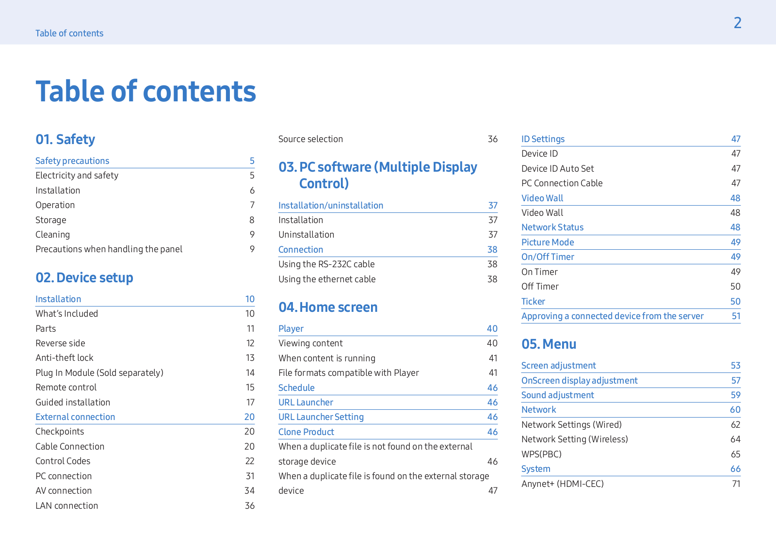
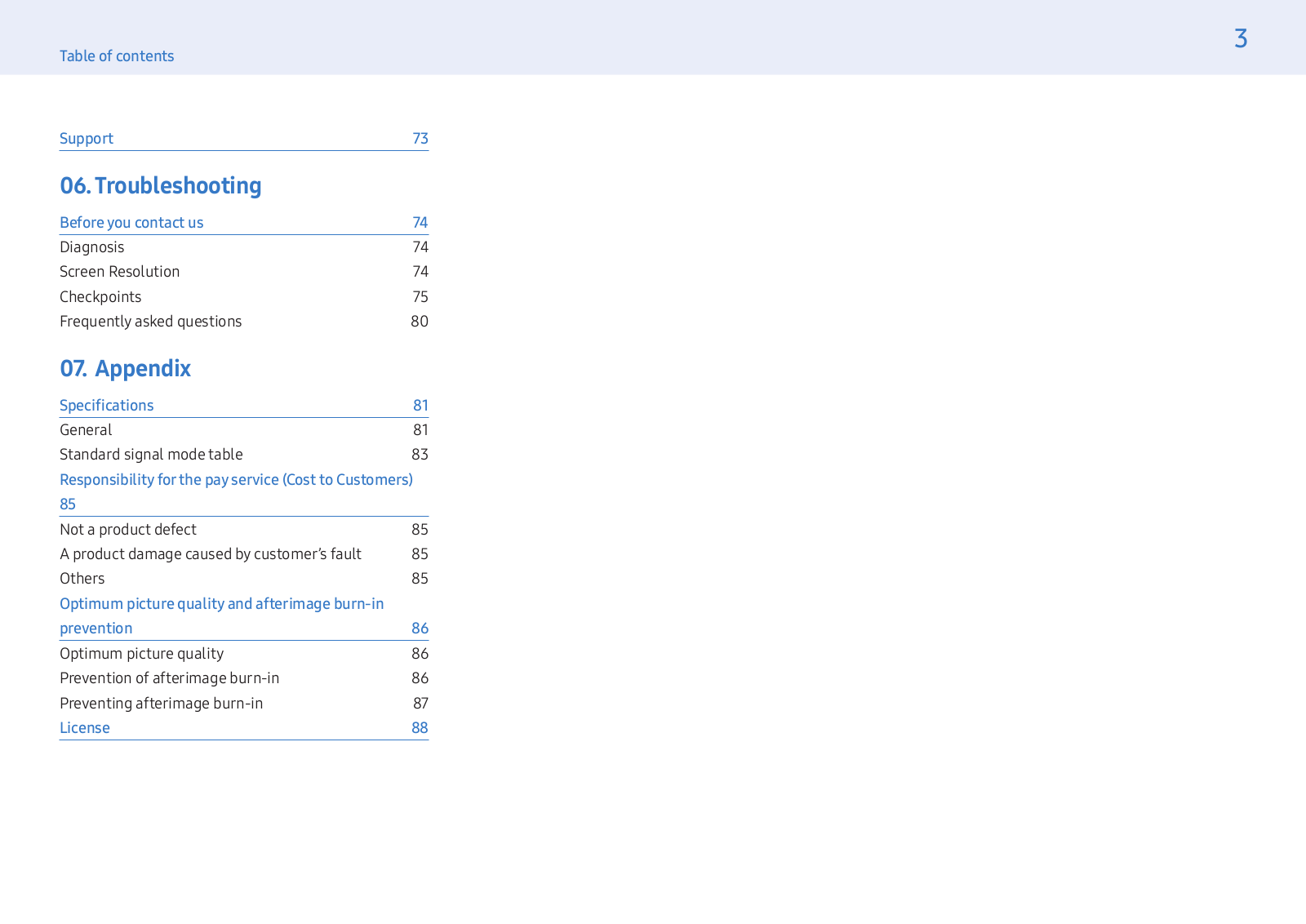
Table of contents
Loading...
Samsung LH49PHFPMGC/EN User Manual
...
Samsung User Manual
Download
Specifications and Main Features
Frequently Asked Questions
User Manual
Download
Loading...
+
61
hidden pages
Unhide
You need points to download manuals.
1 point = 1 manual.
You can buy points or you can get point for every manual you upload.
Buy points
Upload your manuals
 Loading...