

Samsung LH46OHFPVBC/EN User Manual

USER MANUAL
OH46F I OH55F
The colour and the appearance may differ depending on the product, and the specifications are subject to change without prior
notice to improve the performance.
The contents of this manual are subject to change without notice to improve quality.
© Samsung Electronics
Samsung Electronics owns the copyright for this manual.
Use or reproduction of this manual in parts or entirety without the authorization of Samsung Electronics is prohibited.
Trademarks other than that of Samsung Electronics are owned by their respective owners.
• An administration fee may be charged if either
‒ (a) an engineer is called out at your request and there is no defect in the product
(i.e. where you have failed to read this user manual).
‒ (b) you bring the unit to a repair centre and there is no defect in the product
(i.e. where you have failed to read this user manual).
• The amount of such administration charge will be advised to you before any work or home visit is carried out.

Table of contents
Before Using the Product
Safety Precautions 6
Cleaning 6
Storage 6
Electricity and Safety 7
Installation 8
Operation 9
Preparations
Checking the Components 11
Components 11
Parts 12
Parts 12
Reverse Side 13
Anti-theft Lock 14
Remote Control 15
Before Installing the Product (Installation
Guide) 17
Tilting Angle and Rotation 17
Ventilation 17
Installing the Wall Mount 19
Installing the Wall Mount Kit 19
Wall Mount Kit Specifications 19
Remote Control (RS232C) 20
Cable Connection 20
Connection 23
Control Codes 24
Connecting and Using
a Source Device
Before Connecting 32
Pre-connection Checkpoints 32
Before connecting cables 33
Connecting to a PC 34
Connection Using an HDMI-DVI Cable 34
Connection Using an HDMI Cable 34
Connecting to a Video Device 35
Connection Using an HDMI-DVI Cable 35
Connection Using an HDMI Cable 35
Connecting the HDBase-T 36
Connecting to an Audio System 37
Connecting the LAN Cable 37
Changing the Input source 38
Source 38
Web Browser 39
Settings 39
Refresh Options 41
Using MDC
MDC Programme Installation/Uninstallation 42
Installation 42
Uninstallation 42
Connecting to MDC 43
Using MDC via RS-232C (serial data
communications standards) 43
Using MDC via Ethernet 43
Player feature
Player 45
Viewing content 45
When content is running 46
Available menu 46
File Formats Compatible with Player 47
Schedule 52
Clone Product 53
ID Settings 54
Device ID 54
Device ID Auto Set 54
PC Connection Cable 54
Video Wall 55
Video Wall 55
Horizontal x Vertical 55
Screen Position 55
Format 56
2

Table of contents
Network Status 57
Picture Mode 58
On/Off Timer 59
On Timer 59
Off Timer 60
Holiday Management 60
Ticker 61
URL Launcher 62
URL Launcher Settings 63
Approving a connected device from the server 64
Setting the current time 65
Screen Adjustment
Picture Mode 66
Backlight / Contrast / Brightness / Sharpness /
Colour / Tint (G/R)
Colour Temperature 68
White Balance 68
2 Point 68
10 Point 68
Gamma 69
Calibrated value 69
Advanced Settings 70
Dynamic Contrast 70
67
Black Tone 70
Flesh Tone 70
RGB Only Mode 70
Colour Space 70
HDMI UHD Color 71
Motion Lighting 71
Picture Options 72
Colour Tone 72
Digital Clean View 72
HDMI Black Level 73
Film Mode 73
Dynamic Backlight 73
Picture Size 74
Picture Size 74
Fit to Screen 74
Zoom/Position 74
Picture Off 75
Reset Picture 75
OnScreen Display
Display Orientation 76
Onscreen Menu Orientation 76
Source Content Orientation 76
Aspect Ratio 76
Screen Protection 77
Auto Protection Time 77
Screen Burn Protection 77
Message Display 80
Source Info 80
No Signal Message 80
MDC Message 80
Download Status Message 80
Language 81
Reset OnScreen Display 81
Network
Network Status 82
Open Network Settings 82
Network type 82
Network Settings (Wired) 83
Network Setting (Wireless) 85
WPS(PBC) 87
Server Network Settings 88
Connect to server 88
MagicInfo Mode 88
Server Access 88
FTP Mode 88
Proxy server 88
Wi-Fi Direct 89
Mobile Device Manager 90
Access Notification 90
Mobile Device List 90
Device Name 90
3

Table of contents
System
Accessibility 91
Menu Transparency 91
High Contrast 91
Enlarge 91
Start Setup 92
Time 93
Clock Set 93
NTP Settings 93
DST 93
Sleep Timer 93
Power On Delay 93
Auto Source Switching 94
Auto Source Switching 94
Primary Source Recovery 94
Primary Source 94
Secondary Source 94
Power Control 95
Auto Power On 95
Max. Power Saving 95
Standby Control 95
Network Standby 96
Power Button 96
Eco Solution 97
Brightness Limit 97
Energy Saving Mode 97
Eco Sensor 97
Screen Lamp Schedule 98
No Signal Power Off 98
Auto Power Off 98
Fan and Temperature 99
Fan Control 99
Fan Speed Setting 99
Outdoor Mode 99
Temperature Control 99
Input Device Manager 100
Keyboard Language 100
Keyboard type 100
Input Language Shortcut 100
Play via 100
Change PIN 101
Security 102
Safety Lock On 102
USB Auto Play Lock 102
Mobile Connection Lock 102
Remote Management 102
General 103
Smart Security 103
Anynet+ (HDMI-CEC) 104
HDMI Hot Plug 106
Custom Logo 106
Game Mode 107
Empty Storage 107
Reset System 107
Support
Software Update 108
Update now 108
Auto update 108
Contact Samsung 108
Reset All 108
Troubleshooting Guide
Requirements Before Contacting Samsung
Customer Service Centre 109
Testing the Product 109
Checking the Resolution and Frequency 109
Check the followings. 110
Q & A 114
Specifications
General 116
Preset Timing Modes 117
4

Table of contents
Appendix
Responsibility for the Pay Service (Cost to
Customers) 119
Not a product defect 119
A Product damage caused by customer's
fault 119
Others 119
Optimum Picture Quality and Afterimage Burnin Prevention 120
Optimum Picture Quality 120
Prevention of Afterimage Burn-in 120
Licence 122
Terminology 123
5

Chapter 01
Before Using the Product
Safety Precautions
Warning
Caution
A serious or fatal injury may result if instructions are not followed.
Personal injury or damage to properties may result if instructions are
not followed.
Activities marked by this symbol are prohibited.
Instructions marked by this symbol must be followed.
Cleaning
―
Exercise care when cleaning as the panel and exterior of advanced LCDs are easily scratched.
―
Take the following steps when cleaning.
Power off the product and computer.
1
Disconnect the power cord from the product.
2
―
Hold the power cable by the plug and do not touch the cable with wet hands. Otherwise, an electric
shock may result.
Use water and a dry cloth to clean the protection glass.
3
• Wipe with a clean wet cloth.
―
To remove tough stains, wipe using a cloth with a small amount of ethanol based cleaner.
Use a brush to remove any debris from the inlet and outlet opening.
―
To remove tough stains, wipe using a cloth with a small amount of ethanol based cleaner.
―
If washing with water, keep the pressure below 0.5 bar.
Connect the power cord to the product when cleaning is finished.
4
Power on the product and computer.
5
Storage
Due to the characteristics of high-glossy products, using a UV humidifier nearby may create whitecoloured stains on the product.
―
Contact Customer Service Centre if the inside of the product needs cleaning (service fee will be charged).
6

Electricity and Safety
Caution
Warning
Do not use a damaged power cord or plug, or a loose power socket.
• An electric shock or fire may result.
Do not use multiple products with a single power socket.
• Overheated power sockets may cause a fire.
Do not touch the power plug with wet hands. Otherwise, an electric shock may result.
Insert the power plug all the way in so it is not loose.
• An unsecure connection may cause a fire.
Connect the power plug to a grounded power socket (type 1 insulated devices only).
• An electric shock or injury may result.
Do not bend or pull the power cord with force. Be careful not to leave the power cord under a heavy
object.
• Damage to the cord may result in a fire or electric shock.
Do not place the power cord or product near heat sources.
• A fire or electric shock may result.
Clean any dust around the pins of the power plug or the power socket with a dry cloth.
• A fire may result.
Do not disconnect the power cord while the product is being used.
• The product may become damaged by an electric shock.
Only use the power cord provided with your product by Samsung. Do not use the power cord with other
products.
• A fire or electric shock may result.
Keep the power socket where the power cord is connected unobstructed.
• The power cord must be disconnected to cut off power to the product when an issue occurs.
• Note that the product is not completely powered down by using only the power button on the
remote.
Hold the plug when disconnecting the power cord from the power socket.
• An electric shock or fire may result.
7

Installation
Caution
Warning
DO NOT PLACE CANDLES, INSECT REPELLANTS OR CIGARETTES ON TOP OF THE PRODUCT. DO NOT
INSTALL THE PRODUCT NEAR HEAT SOURCES.
• A fire may result.
Have a technician install the wall-mount hanger.
• Installation by an unqualified person can result in an injury.
• Only use approved cabinets.
Do not install the product in poorly ventilated spaces such as a bookcase or closet.
• An increased internal temperature may cause a fire.
When installing the product, keep it at a distance from the wall so that it is well ventilated.
―
Refer to the Outdoor Installation Guide. (http://displaysolutions.samsung.com)
• An increased internal temperature may cause a fire.
Keep the plastic packaging out of the reach of children.
• Children may suffocate.
Do not install the product on an unstable or vibrating surface (insecure shelf, sloped surface, etc.)
• The product may fall and become damaged and/or cause an injury.
• Using the product in an area with excess vibration may damage the product or cause a fire.
Do not drop the product while moving.
• Product failure or personal injury may result.
Do not set down the product on its front.
• The screen may become damaged.
When installing the product on a cabinet or shelf, make sure that the bottom edge of the front of the
product is not protruding.
• The product may fall and become damaged and/or cause an injury.
• Install the product only on cabinets or shelves of the right size.
Set down the product gently.
• Product failure or personal injury may result.
If the product is installed in an unusual location, the surrounding environment may cause a serious
quality problem. Therefore, be sure to contact Samsung Customer Service Center before installation.
• Places where many fine dusts are generated, places where chemicals are used, places with too
high or low temperatures, places with a lot of moisture or water, transportation equipment such as
vehicles, airports and stations used continuously for a long time, and more.
Do not install the product within the reach of young children.
• The product may fall and injure children.
• As the front is heavy, install the product on a flat and stable surface.
Edible oil, such as soybean oil, can damage or deform the product. Do not install the product in a kitchen
or near a kitchen counter.
Precautions during installation and storage
• After opening the cover, install the product within 1 hour under humidity of 60% or below. (P. 33)
• Keep the predefined humidity while opening the cover or assembling the housing (e.g. connection of
external device, F/W update).
• During operation and storage of the product, be sure to attach the cover.
8

Operation
Warning
There is a high voltage inside the product. Never disassemble, repair or modify the product yourself.
• A fire or electric shock may result.
• Contact Samsung Customer Service Centre for repairs.
Before moving the product, turn off the power switch and disconnect the power cable and all other
connected cables.
• Otherwise, the power cord may be damaged and a fire or electric shock may result.
If the product generates abnormal sounds, a burning smell or smoke, disconnect the power cord
immediately and contact Samsung Customer Service Centre.
• An electric shock or fire may result.
Do not let children hang from the product or climb on top of it.
• Children may become injured or seriously harmed.
If the product is dropped or the outer case is damaged, turn off the power switch and disconnect the
power cord. Then contact Samsung Customer Service Centre.
• Continued use can result in a fire or electric shock.
Do not leave heavy objects or items that children like (toys, sweets, etc.) on top of the product.
• The product or heavy objects may fall as children try to reach for the toys or sweets resulting in a
serious injury.
Do not lift or move the product by pulling the power cord or any cable.
• Product failure, an electric shock or fire may result from a damaged cable.
Do not use or keep combustible spray or an inflammable substance near the product.
• An explosion or fire may result.
Ensure the vents are not blocked by tablecloths or curtains.
• An increased internal temperature may cause a fire.
Do not insert metallic objects (chopsticks, coins, hairpins, etc) or objects that burn easily (paper, matches,
etc) into the product (via the vent or input/output ports, etc).
• Be sure to power off the product and disconnect the power cord when water or other foreign
substances have entered the product. Then contact Samsung Customer Service Centre.
• Product failure, an electric shock or fire may result.
Do not block the vent on the product. The product may not function properly due to potential
overheating.
Do not attempt to insert your fingers or objects into the vents.
• Product failure or personal injury may result.
Do not drop objects on the product or apply impact.
• A fire or electric shock may result.
Do not move the product by pulling the power cord or any cable.
• Product failure, an electric shock or fire may result from a damaged cable.
If a gas leakage is found, do not touch the product or power plug. Also, ventilate the area immediately.
• Sparks can cause an explosion or fire.
9

Caution
Leaving the screen fixed on a stationary image for an extended period of time may cause afterimage
burn-in or defective pixels.
• Activate power-saving mode or a moving-picture screen saver if you will not be using the product for
an extended period of time.
Disconnect the power cord from the power socket if you do not plan on using the product for an extended
period of time (vacation, etc).
• Dust accumulation combined with heat can cause a fire, electric shock or electric leakage.
Use the product at the recommended resolution and frequency.
• Your eyesight may deteriorate.
Do not hold the product upside-down or move it by holding the stand.
• The product may fall and become damaged or cause an injury.
Looking at the screen too close for an extended period of time can deteriorate your eyesight.
Rest your eyes for more than 5 minutes for every 1 hour of product use.
• Eye fatigue will be relieved.
Do not touch the screen when the product has been turned on for an extended period of time as it will
become hot.
Store small accessories out of the reach of children.
When replacing the battery, insert it with the right polarity (+, -).
• Otherwise, the battery may become damaged or it may cause fire, personal injury or damage due to
leakage of the internal liquid.
Use only the specified standardised batteries, and do not use a new battery and a used battery at the
same time.
• Otherwise, the batteries may be damaged or cause fire, personal injury or damage due to a leakage
of the internal liquid.
The batteries (and rechargeable batteries) are not ordinary refuse and must be returned for recycling
purposes. The customer is responsible for returning the used or rechargeable batteries for recycling.
• The customer can return used or rechargeable batteries to a nearby public recycling centre or to a
store selling the same type of the battery or rechargeable battery.
Exercise caution when adjusting the product angle or stand height.
• Your hand or finger may get stuck and injured.
• Tilting the product at an excessive angle may cause the product to fall and an injury may result.
Do not place heavy objects on the product.
• Product failure or personal injury may result.
When using headphones or earphones, do not turn the volume too high.
• Having the sound too loud may damage your hearing.
Be careful that children do not place the battery in their mouths when removed from the remote control.
Place the battery in a location that children or infants cannot reach.
• If children have had the battery in their mouths, consult your doctor immediately.
10
Chapter 02
Preparations
– Contact the vendor where you
purchased the product if any
components are missing.
– The pictures may look different from
the actual components.
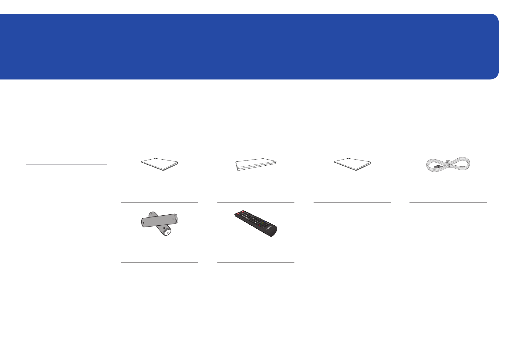
Checking the Components
Components
QUICK SETUP GUIDE
Warranty card
(Not available in some locations)
Regulatory guide Power cord
– A stand is not provided with the
product. To install a stand, you can
purchase one separately.
-
-
Batteries
(Not available in some locations)
+
+
Remote Control
11
Parts
Parts
―
The colour and shape of parts may differ from what is shown. Specifications are subject to change without notice to improve quality.
POWER
Remote sensor
Parts Description
Remote sensor
Use the remote control within 7 m to 10 m from the sensor on the product at an angle of 30° from the left and right.
―
Store used batteries out of reach of children and recycle.
―
Do not use a new and used battery together. Replace both batteries at the same time.
―
Remove batteries when the remote control is not to be used for an extended period of time.
Press a button on the remote control pointing at the sensor on the front of the product to perform the corresponding function.
―
Using other display devices in the same space as the remote control of this product can cause the other display devices to be inadvertently controlled.
12
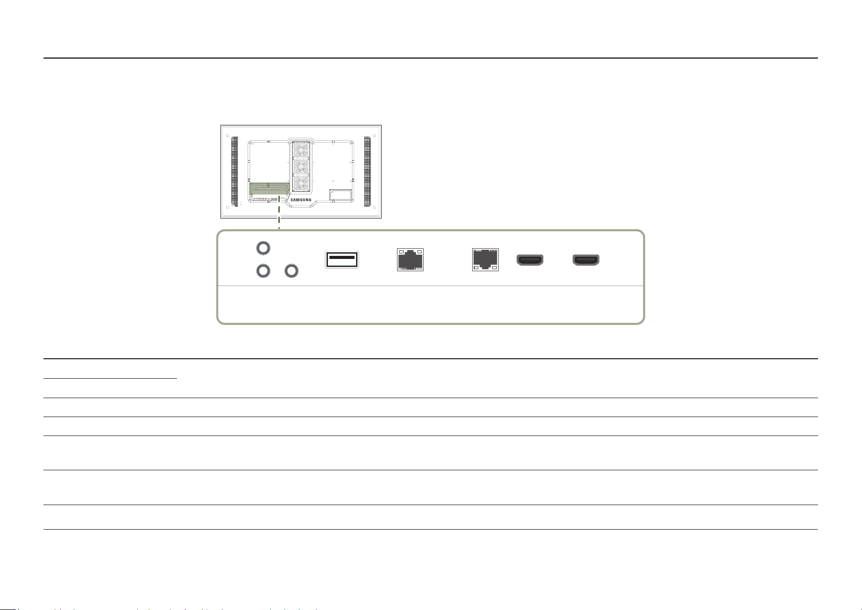
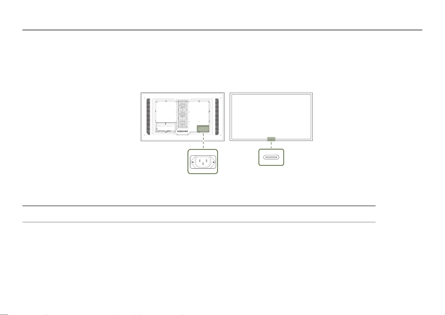
Reverse Side
―
The colour and shape of parts may differ from what is shown. Specifications are subject to change without notice to improve quality.
RS232C
IN
OUT
AUDIO
OUT
USB
RJ45
(LAN OUT)
Port Description
RS232C IN Connects to MDC using an RS232C adapter.
RS232C OUT
AUDIO OUT Outputs sound to an audio device via an audio cable.
USB Connect to a USB memory device.
RJ45 (LAN OUT)
HDBT (LAN IN) - Sends the HDMI signal to a connected LAN cable using an HDBaseT transmitter.
HDMI IN 1, HDMI IN 2 Connects to a source device using a HDMI cable or HDMI-DVI cable.
- Wired LAN connection port used to connect an external device such as a laptop to connect to the Internet.
- Connects to MDC using a LAN cable.
- Connects to MDC using a LAN cable.
HDBT
(LAN IN)
HDMI IN 1 HDMI IN 2
13
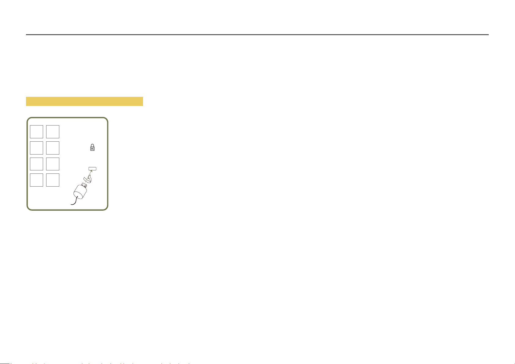
Anti-theft Lock
―
An anti-theft lock allows you to use the product securely even in public places.
―
The locking device shape and locking method depend on the manufacturer. Refer to the user guide provided with your anti-theft locking device for details.
―
The following images are for reference only. Real-life situations may differ from what is shown in the images.
To lock an anti-theft locking device:
Fix the cable of your anti-theft locking device to a heavy object such as a desk.
1
Put one end of the cable through the loop on the other end.
2
Insert the locking device into the anti-theft lock slot at the back of the product.
3
Lock the locking device.
4
‒ An anti-theft locking device can be purchased separately.
‒ Refer to the user guide provided with your anti-theft locking device for details.
‒ Anti-theft locking devices can be purchased at electronics retailers or online.
14
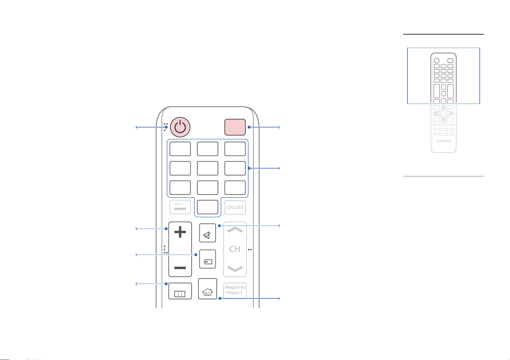
Remote Control
MagicInfo
Player I
CH
DEL-/--
CH LIST
―
Using other display devices in the same space as the remote control of this product can cause the other display devices to be inadvertently controlled.
―
A button without a description in the image below is not supported on the product.
Power on the product.
Adjust the volume.
Change the input source.
Display or hide the onscreen display menu, or
return to the previous menu.
.QZ
1
GHI
4
PRS
7
VOL
MENU
ABC
2
JKL
5
TUV
8
SYMBOL
0
MUTE
SOURCE
HOME
POWER
OFF
DEF
3
MNO
6
WXY
9
Power off the product.
Number buttons
Enter the password in the OSD menu.
– Remote control button functions may
differ for different products.
– Remove batteries when the remote
control is not to be used for an
extended period of time.
Mute the sound.
Unmuting the sound: Press MUTE again or press
the volume control (+ VOL -) button.
Player Launch Button.
15
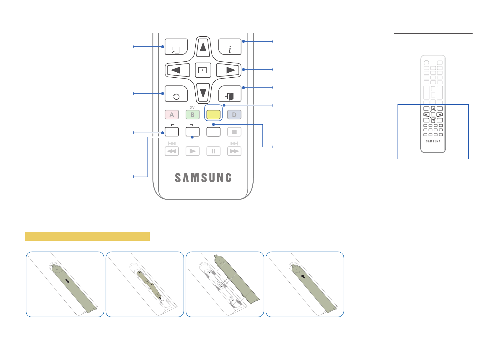
DVI
B
Quickly select frequently used functions by
pressing it while a USB content is playing.
Return to the previous menu.
TOOLS INFO
EXITRETURN
Display information about the current input
source.
Move to the upper, lower, left or right menu, or
adjust an option's setting.
Confirm a menu selection.
Exit the current menu.
If multiple products are connected through the
Video Wall feature, press the SET button and
enter a Device ID using the numeric buttons.
Control the product using the remote control.
Cancel a value that has been set using the SET
button and control all connected products using
the remote control.
To place batteries in the remote control
PC
A
SET
IR control
UNSET
HDMI
C
LOCK
DP
D
Manually select a connected input source from
HDMI 1 and HDMI 2.
It sets safe lock function.
– Remote control button functions may
differ for different products.
16
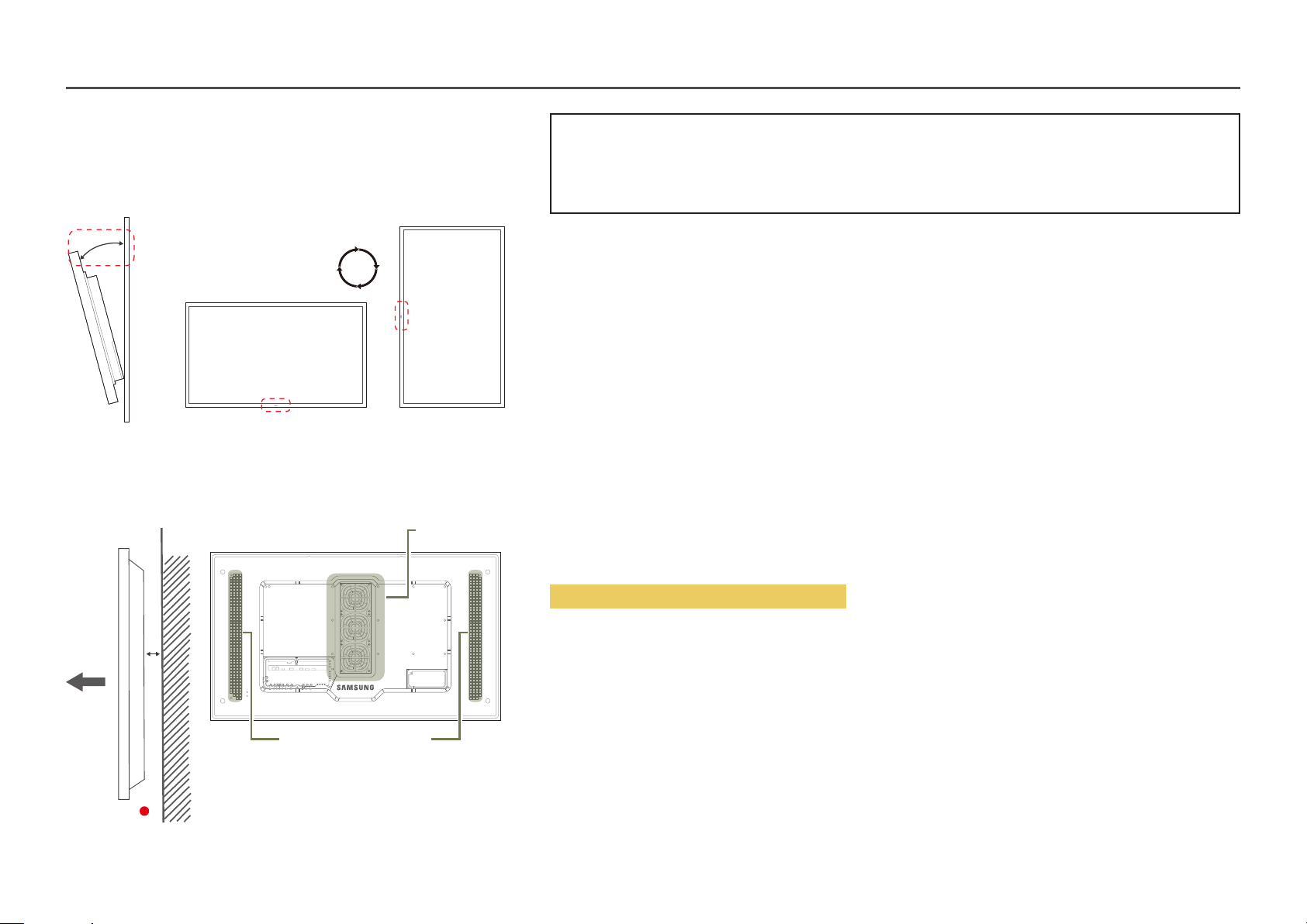
Before Installing the Product (Installation Guide)
15˚
To prevent injury, this apparatus must be securely attached to the floor/wall in accordance with the installation instructions.
• Ensure that an authorised installation company installs the wall mount.
• Otherwise, it may fall and cause personal injury.
• Make sure to install the specified wall mount.
Tilting Angle and Rotation
―
Contact Samsung Customer Service Centre for further details.
• The product can be tilted at a maximum angle of 15° from a perpendicular wall surface.
• To use the product vertically (portrait), turn it clockwise so that the LED is pointing down.
A
B
Figure 1.1 Side view
Air vent
Air intake
Ventilation
Installation on a Perpendicular Wall
A Minimum 50 mm
B Ambient temperature: Under 50°C
• When installing the product on a perpendicular wall, allow at least 50 mm of space between the product and wall surface
for ventilation and ensure that the ambient temperature is kept below 50°C.
―
Do not block the vent on the product.
―
Refer to the Outdoor Installation Guide. (http://displaysolutions.samsung.com)
17
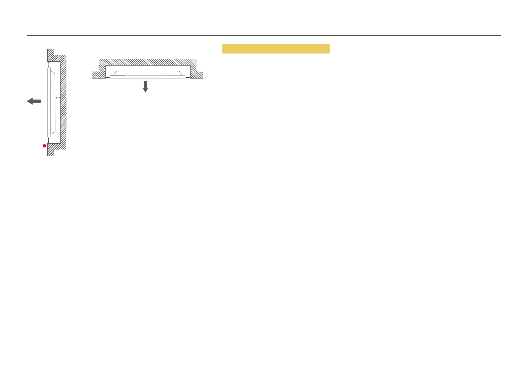
B
A
B
C
Figure 1.2 Side view
Figure 1.3 Side view
B B
Installation on an Indented Wall
―
Contact Samsung Customer Service Centre for further details.
Plane view
A Minimum 50 mm
B Minimum 50 mm
C Ambient temperature: Under 50°C
―
When installing the product on an indented wall, allow at least the space specified above between the product and wall for
ventilation and ensure that the ambient temperature is kept below 50°C.
―
Refer to the Outdoor Installation Guide. (http://displaysolutions.samsung.com)
18
Installing the Wall Mount
―
The colour and shape of parts may differ from what is shown. Specifications are subject to change without notice to improve quality.
Installing the Wall Mount Kit
The wall mount kit (sold separately) allows you to mount the product on the wall.
For detailed information on installing the wall mount, see the instructions provided with the wall mount.
We recommend you contact a technician for assistance when installing the wall mount bracket.
Samsung Electronics is not responsible for any damage to the product or injury to yourself or others if you select to install the wall mount on your own.
Wall Mount Kit Specifications
―
Install your wall mount on a solid wall perpendicular to the floor. If you install the
product on a slanted wall, it may fall and result in severe personal injury.
Before attaching the wall mount to surfaces other than plaster board, please contact
your nearest service center for additional information.
• Samsung wall mount kits contain a detailed installation manual and all parts necessary for assembly are provided.
• Do not use screws that are longer than the standard length or do not comply with the VESA standard screw specifications.
Screws that are too long may cause damage to the inside of the product.
• For wall mounts that do not comply with the VESA standard screw specifications, the length of the screws may differ
depending on the wall mount specifications.
• Do not fasten the screws too firmly. This may damage the product or cause the product to fall, leading to personal injury.
Samsung is not liable for these kinds of accidents.
• Samsung is not liable for product damage or personal injury when wall mount is used or the consumer fails to follow the
product installation instructions.
• Do not mount the product at more than a 15 degree tilt.
• Always have two people mount the product on a wall.
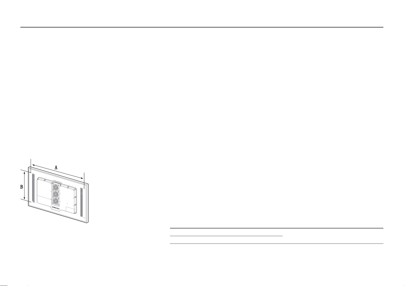
• Standard dimensions for wall mount kits are shown in the table below.
Unit: mm (inches)
Model name Screw hole specs (A * B) in
Standard Screw Quantity
millimetres
OH46F 995 x 500 (39.2 x 19.7)
OH55F 1186 x 560 (46.7 x 22.0)
―
Do not install your Wall Mount Kit while your product is turned on. It may result in personal injury due to electric shock.
M8 4
19
Remote Control (RS232C)
• Pin assignment
Cable Connection
RS232C Cable
Interface RS232C (9 pins)
Pin TxD (No.2), RxD (No.3), GND (No.5)
Bit rate 9600 bps
Data bits 8 bit
Parity None
Stop bit 1 bit
Flow control None
Maximum length 15 m (only shielded type)
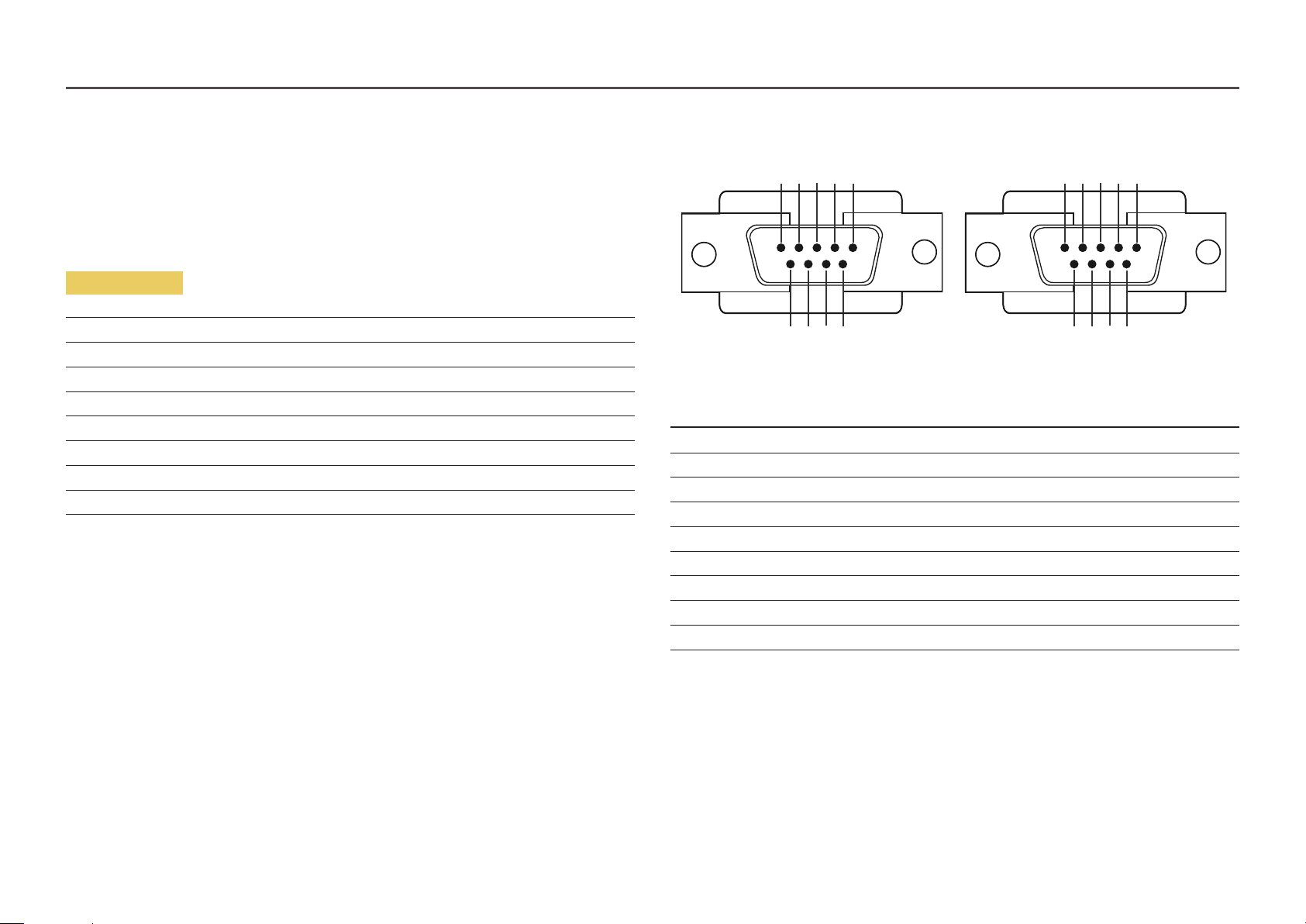
1 2 3 4 5
6 7 8 9
<Male type> <Female type>
Pin Signal
1 Detect data carrier
2 Received data
3 Transmitted data
4 Prepare data terminal
5 Signal ground
6 Prepare data set
7 Send request
8 Clear to send
9 Ring indicator
5 4 3 2 1
9 8 7 6
20
• RS232C cable
Connector: 9-Pin D-Sub to Stereo Cable
16
5
9
-P1-
-P1- -P1- -P2- -P2-
Male type Rx
Tx
Gnd
3
2
5
----------
----------
----------
2
1
3
Tx
Rx
Gnd
STEREO
PLUG
(3.5ø)
3
2
1
-P2-
LAN Cable
• Pin assignment
1 2 3 4 5 6 7 8
Pin No Standard Colour Signal
1 White and orange TX+
2 Orange TX-
3 White and green RX+
4 Blue NC
5 White and blue NC
6 Green RX-
7 White and brown NC
8 Brown NC
21
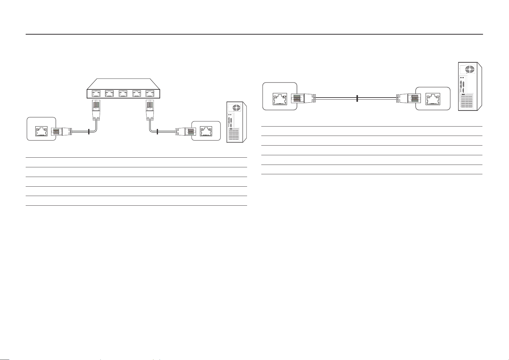
• Connector : RJ45
Direct LAN cable (PC to HUB)
Cross LAN cable (PC to PC)
HUB
P1P2
RJ45
Signal P1 P2 Signal
TX+ 1 <--------> 1 TX+
TX- 2 <--------> 2 TX-
RX+ 3 <--------> 3 RX+
RX- 6 <--------> 6 RX-
P1
P2
RJ45
RJ45
Signal P1 P2 Signal
TX+ 1 <--------> 3 RX+
TX- 2 <--------> 6 RX-
RX+ 3 <--------> 1 TX+
RX- 6 <--------> 2 TX-
P1 P2
22
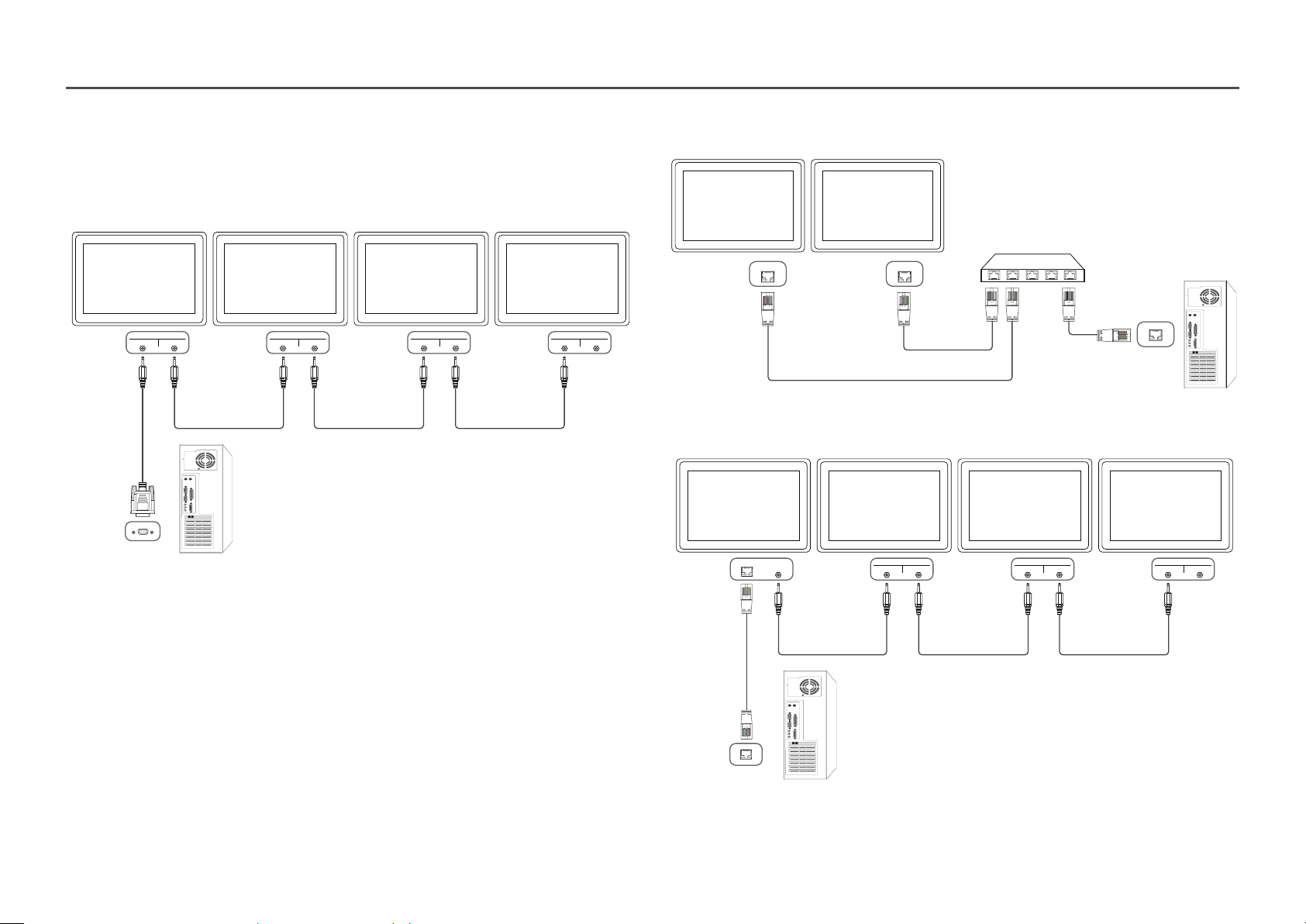
Connection
―
Ensure you connect each of the adapters to the correct RS232C IN or OUT port on the product.
• Connection 1
• Connection 2
RJ45 RJ45
RS232C
IN OUT
RS232C
IN OUT
RS232C
IN OUT
RS232C
IN OUT
• Connection 3
RJ45 RS232C
RS232C
OUT
IN OUT
RS232C
IN OUT
RS232C
IN OUT
23
Control Codes
Viewing control state (Get control command)
Header Command ID Data length Checksum
0xAA Command type 0
Controlling (Set control command)
Header Command ID Data length Data Checksum
0xAA Command type 1 Value
Command
No. Command type Command Value range
1 Power control 0x11 0~1
2 Volume control 0x12 0~100
3 Input source control 0x14 -
4 Screen mode control 0x18 -
5 Screen size control 0x19 0~255
6 Video wall mode control 0x5C 0~1
7 Safety Lock 0x5D 0~1
8 Video Wall On 0x84 0~1
9 Video Wall User Control 0x89 -
E.g. Power On & ID=0
Header Command ID Data length Data 1 Checksum
0xAA 0x11 1 "Power"
Header Command ID Data length Data 1 12
0xAA 0x11 1 1
• To control all devices connected by a serial cable simultaneously irrespective of IDs, set the ID
as "0xFE" and transmit commands. Commands will be executed by each device but ACK will not
respond.
• All communications take place in hexadecimals. The checksum is calculated by adding up all values
except the header. If a checksum adds up to be more than 2 digits as shown below (11+FF+01+01=112),
the first digit is removed.
24
Power control
Volume control
• Function
A product can be powered on and off using a PC.
• Viewing power state (Get Power ON / OFF Status)
Header Command ID Data length Checksum
0xAA 0x11 0
• Setting power ON/Off (Set Power ON / OFF)
Header Command ID Data length Data Checksum
0xAA 0x11 1 "Power"
"Power": Power code to be set on a product.
1: Power ON
0: Power OFF
• Ack
Header Command ID Data length Ack/Nak r-CMD Val1 Checksum
0xAA 0xFF 3 'A' 0x11 "Power"
"Power": Power code to be set on a product.
• Nak
Header Command ID Data length Ack/Nak r-CMD Val1 Checksum
0xAA 0xFF 3 'N' 0x11 "ERR"
• Function
The volume of a product can be adjusted using a PC.
• Viewing volume state (Get Volume Status)
Header Command ID Data length Checksum
0xAA 0x12 0
• Setting the volume (Set Volume)
Header Command ID Data length Data Checksum
0xAA 0x12 1 "Volume"
"Volume": Volume value code to be set on a product. (0-100)
• Ack
Header Command ID Data length Ack/Nak r-CMD Val1 Checksum
0xAA 0xFF 3 'A' 0x12 "Volume"
"Volume": Volume value code to be set on a product. (0-100)
• Nak
Header Command ID Data length Ack/Nak r-CMD Val1 Checksum
0xAA 0xFF 3 'N' 0x12 "ERR"
"ERR" : A code showing what error has occurred.
"ERR" : A code showing what error has occurred.
25
Input source control
• Function
The input source of a product can be changed using a PC.
• Viewing input source state (Get Input Source Status)
Header Command ID Data length Checksum
0xAA 0x14 0
• Setting the input source (Set Input Source)
Header Command ID Data length Data Checksum
0xAA 0x14 1 "Input Source"
"Input Source": An input source code to be set on a product.
0x0C Input source
0x20 MagicInfo
0x21 HDMI1
0x22 HDMI1_PC
0x23 HDMI2
0x24 HDMI2_PC
0x55 HDBT
―
HDMI1_PC and HDMI2_PC cannot be used with the Set command. They only respond to "Get" commands.
―
Available input sources may vary depending on the model.
―
MagicInfo is only available with models that contain the MagicInfo function.
• Ack
Header Command ID Data length Ack/Nak r-CMD Val1 Checksum
0xAA 0xFF 3 'A' 0x14 "Input
Source"
"Input Source": An input source code to be set on a product.
• Nak
Header Command ID Data length Ack/Nak r-CMD Val1 Checksum
0xAA 0xFF 3 'N' 0x14 "ERR"
"ERR" : A code showing what error has occurred.
26
Screen mode control
• Function
The screen mode of a product can be changed using a PC.
Screen mode cannot be controlled when the Video Wall function is enabled.
• Viewing screen status (Get Screen Mode Status)
Header Command ID Data length Checksum
0xAA 0x18 0
• Setting the picture size (Set Picture Size)
Header Command ID Data length Data Checksum
0xAA 0x18 1 "Screen Mode"
"Screen Mode": A code that sets the product status
0x01 16 : 9
0x04 Zoom
0x31 Wide Zoom
0x0B 4 : 3
• Nak
Header Command ID Data length Ack/Nak r-CMD Val1 Checksum
0xAA 0xFF 3 'N' 0x18 "ERR"
"ERR": A code showing what error has occurred
Screen size control
• Function
The screen size of a product can be changed using a PC.
• Viewing the screen size (Get Screen Size Status)
Header Command ID Data length Checksum
0xAA 0x19 0
• Ack
Header Command ID Data
length
0xAA 0xFF 3 'A' 0x19 "Screen Size"
Ack/Nak r-CMD Val1 Checksum
• Ack
Header Command ID Data length Ack/Nak r-CMD Val1 Checksum
0xAA 0xFF 3 'A' 0x18 "Screen
Mode"
"Screen Mode": A code that sets the product status
"Screen Size": product screen size (range: 0 – 255, unit: inch)
• Nak
Header Command ID Data
length
0xAA 0xFF 3 'N' 0x19 "ERR"
"ERR": A code showing what error has occurred
Ack/Nak r-CMD Val1 Checksum
27
Video Wall Mode Control
Safety Lock On
• Function
Video Wall mode can be activated on a product using a PC.
This control is only available on a product whose Video Wall is enabled.
• Viewing video wall mode (Get Video Wall Mode)
Header Command ID Data length Checksum
0xAA 0x5C 0
• Setting the video wall (Set Video Wall Mode)
Header Command ID Data length Data Checksum
0xAA 0x5C 1 "Video Wall Mode"
"Video Wall Mode": A code used to activate Video Wall mode on a product
1: Full
0: Natural
• Ack
Header Command ID Data
length
0xAA 0xFF 3 'A' 0x5C "Video Wall
"Video Wall Mode": A code used to activate Video Wall mode on a product
• Nak
Header Command ID Data
length
0xAA 0xFF 3 'A' 0x5C "ERR"
"ERR": A code showing what error has occurred
Ack/Nak r-CMD Val1 Checksum
Mode"
Ack/Nak r-CMD Val1 Checksum
• Function
PC can be used to turn the Safety Lock On function on or off on a product.
This control is available regardless of whether or not the power is turned on.
• Viewing the safety lock state (Get Safety Lock Status)
Header Command ID Data length Checksum
0xAA 0x5D 0
• Enabling or disabling safety lock (Set Safety Lock Enable / Disable)
Header Command ID Data length Data Checksum
0xAA 0x5D 1 "Safety Lock"
"Safety Lock": Safety lock code to be set on a product
1: ON
0: OFF
• Ack
Header Command ID Data
length
0xAA 0xFF 3 'A' 0x5D "Safety Lock"
"Safety Lock": Safety lock code to be set on a product
• Nak
Header Command ID Data
length
0xAA 0xFF 3 'N' 0x5D "ERR"
"ERR": A code showing what error has occurred
Ack/Nak r-CMD Val1 Checksum
Ack/Nak r-CMD Val1 Checksum
28
Video Wall On
Video Wall User Control
• Function
Turn Video Wall on or off on the product from your computer.
• Get Video Wall On/Off Status
Header Command ID Data length Checksum
0xAA 0x84 0
• Set Video Wall On/Off
Header Command ID Data length Data Checksum
0xAA 0x84 1 V.Wall_On
• V.Wall_On: Video Wall code to be assigned to the product
1: Video Wall ON
0: Video Wall OFF
• Ack
Header Command ID Data length Ack/Nak r-CMD Val1 Checksum
0xAA 0xFF 3 'A' 0x84 V.Wall_On
V.Wall_On : Same as above
• Nak
Header Command ID Data length Ack/Nak r-CMD Val1 Checksum
0xAA 0xFF 3 'N' 0x84 ERR
• Function
Turn the Video Wall function on or off on the product from your computer.
• Get Video Wall Status
Header Command ID Data length Checksum
0xAA 0x89 0
• Set Video Wall
Header Command ID Data length Val1 Val2 Checksum
0xAA 0x89 2 Wall_Div Wall_SNo
Wall_Div: Video Wall Divider code assigned to the product
"ERR": A code showing what error has occurred
29

10x10 Video Wall Model
1 2 3 4 5 6 7 8 9 10 11 12 13 14
Off
1
2
3
4
5
6
7
8
9
10
11
12
13
14
15
0x00 0x00 0x00 0x00 0x00 0x00 0x00 0x00 0x00 0x00 0x00 0x00 0x00 0x00
0x11 0x12 0x13 0x14 0x15 0x16 0x17 0x18 0x19 0x1A 0x1B 0x1C 0x1D 0x1E
0x21 0x22 0x23 0x24 0x25 0x26 0x27 0x28 0x29 0x2A 0x2B 0x2C 0x2D 0x2E
0x31 0x32 0x33 0x34 0x35 0x36 0x37 0x38 0x39 0x3A 0x3B 0x3C 0x3D 0x3E
0x41 0x42 0x43 0x44 0x45 0x46 0x47 0x48 0x49 0x4A 0x4B 0x4C 0x4D 0x4E
0x51 0x52 0x53 0x54 0x55 0x56 0x57 0x58 0x59 0x5A 0x5B 0x5C 0x5D 0x5E
0x61 0x62 0x63 0x64 0x65 0x66 0x67 0x68 0x69 0x6A 0x6B 0x6C 0x6D 0x6E
0x71 0x72 0x73 0x74 0x75
0x81 0x82 0x83 0x84 0x85 0x86 0x87 0x88 0x89 0x8A 0x8B 0x8C N/A N/A
0x91 0x92 0x93 0x94 0x95 0x96 0x97 0x98 0x99 0x9A 0x9B N/A N/A N /A
0xA1 0xA2 0xA3 0xA4 0xA5 0xA6 0xA7 0xA8 0xA9 0xAA N/A N/A N /A N/A
0xB1 0xB2 0xB3 0xB4 0xB5 0xB6 0xB7 0xB8 0xB9 N/A N/A N/A N /A N/A
0xC1 0xC2 0xC3 0xC4 0xC5 0xC6 0xC7 0xC8 N/A N/A N/A N /A N /A N/A
0xD1 0xD2 0xD3 0xD4 0xD5 0xD6 0xD7 N/A N/A N/A N /A N /A N/A N/A
0xE1 0xE2 0xE3 0xE4 0xE5 0xE6 0xE7 N/A N/A N/A N /A N/A N/A N /A
0xF1 0xF2 0xF3 0xF4 0xF5 0xF6 N/A N /A N/A N/A N /A
0x76 0x77 0x78 0x79 0x7A 0x7B 0x7C 0x7D 0x7E
N/A N/A N /A
15
0x00
0x1F
0x2F
0x3F
0x4F
0x5F
0x6F
N/A
N/A
N/A
N/A
N/A
N/A
N/A
N/A
N/A
30
 Loading...