

Samsung LE32R71B 07 Alignment & Adjustment

3 Alignments and Adjustments
3-1
3 Alignments and Adjustments
3-1 Ser vice Instr uction
1. Usually, a color TV-VCR needs only slight touch-up adjustment upon installation.
Check the basic characteristics such as height, horizontal and vertical sync.
2. Use the specified test equipment or its equivalent.
3. Correct impedance matching is essential.
4. Avoid overload. Excessive signal from a sweep generator might overload the front-end
of the TV. When inserting signal markers, do not allow the marker generator to distort
test result.
5. Connect the TV only to an AC power source with voltage and frequency as specified on
the backcover nameplate.
6. Do not attempt to connect or disconnect any wire while the TV is turned on. Make sure
that the power cord is disconnected before replacing any parts.
7. To protect aganist shock hazard, use an isolation transform.
3 Alignments and Adjustments
3-2
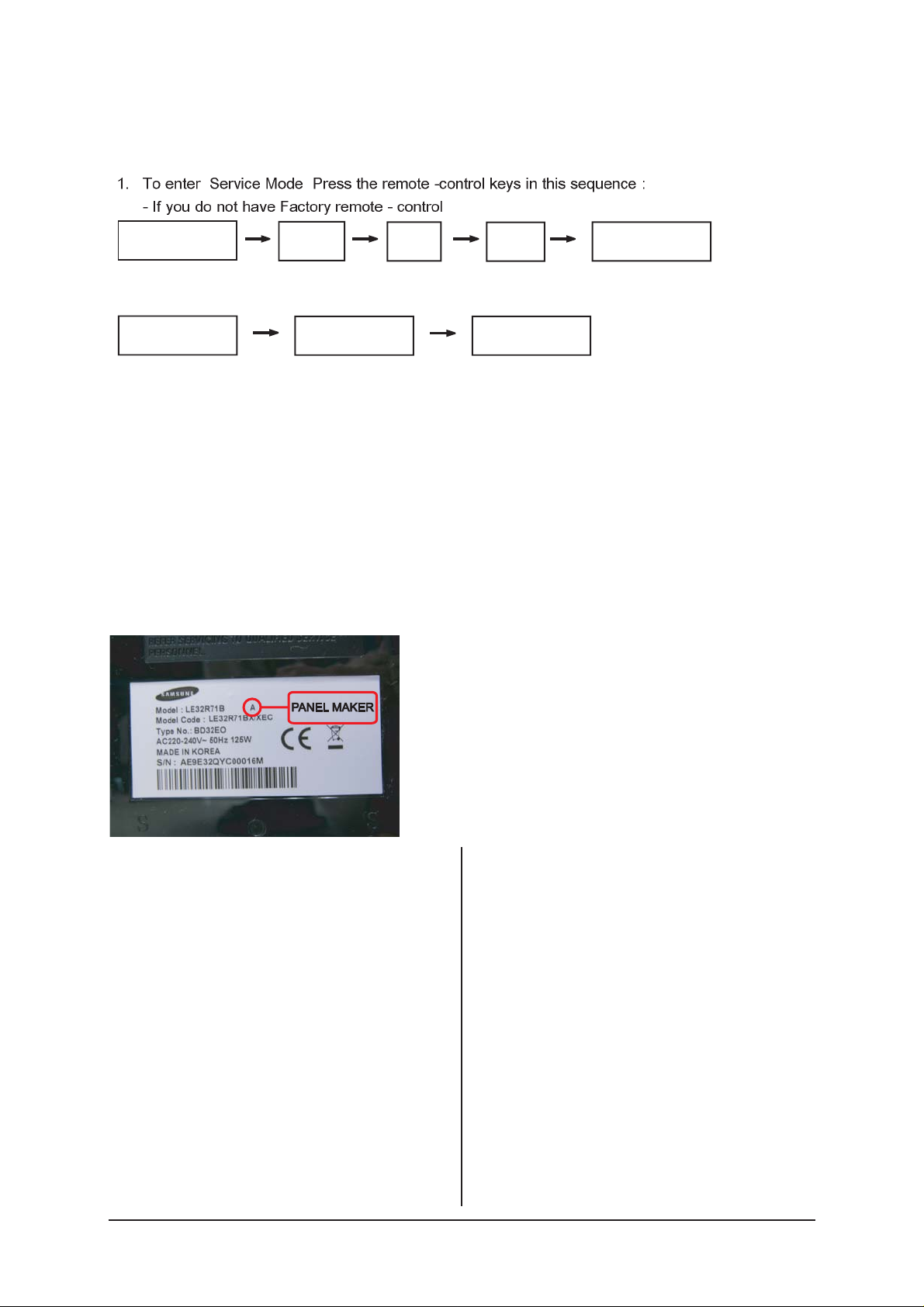
3-2 How to Access Service Mode
3-2-1 Entering Factory Mode
" "
- If you have Factory remote - control
- The buttons are active in the service mode.
1. Remote - Control Key : Power, Arrow Up, Arrow Down, Arrow Left
Arrow Right, Menu, Enter, Number Key(0~9)
2. Function - Control Key : Power, CH +, CH -, VOL +, VOL -,
Menu, TV/VIDEO(Enter)
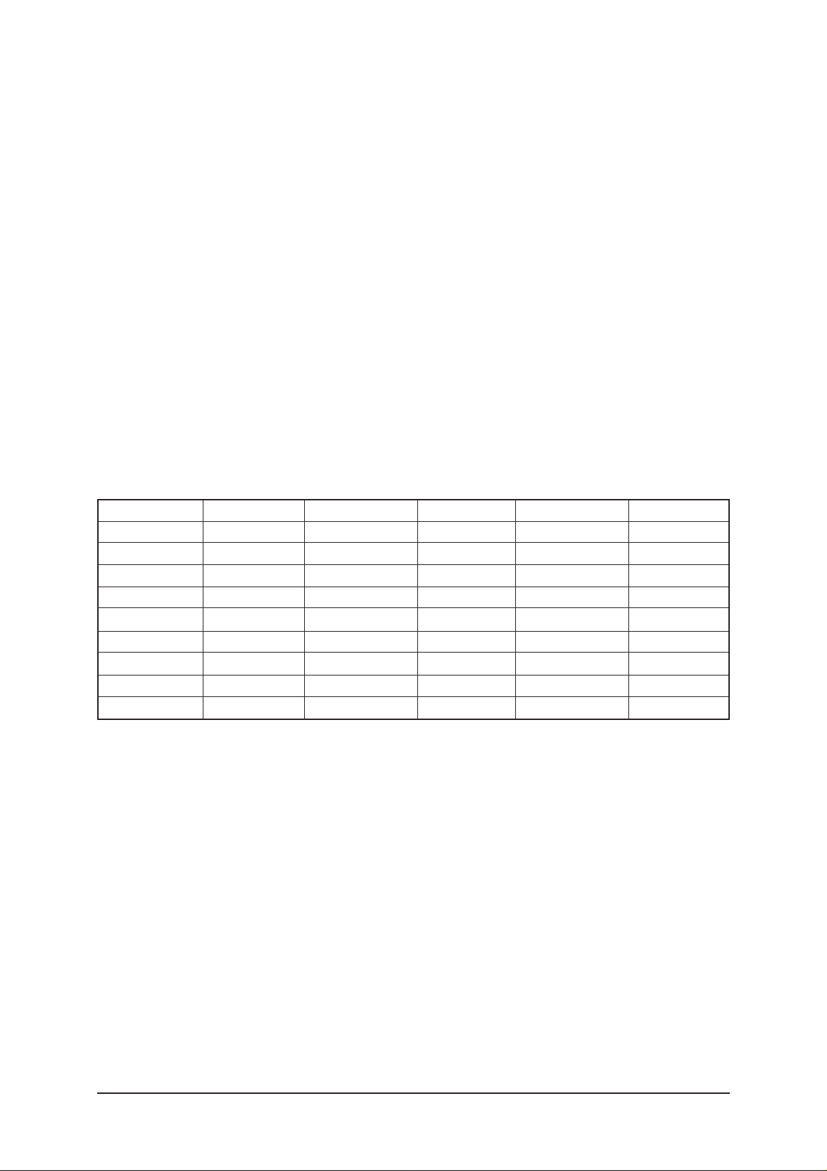
3-2-2 Panel Check
Specially for LE26,32R7**, You have to check Panel Maker Because of different adjustments as follows.
First of all, Check the label rating!
1) Label Rating File
If Panel Mark is "A", Set the factory mode
indicating as follows.
Panel BOM(Bill of material) : BN07-00289A
Connector between Panel and Power Unit
: BN39-00603M (300mm)
* Option Byte
1. Gamma "AUO"
2. Panel Option "AUO"
If Panel Mark is "S" or not printed.
Set the factory mode indicating as follows.
Panel BOM(Bill of material) : BN07-00247A
Connector between Panel and Power Unit
: BN39-00603M (300mm)
* Option Byte
1. Gamma "AMLCD"
2. Panel Option "AMLCD_INT"
If Panel Mark is "C" , Set the Factory mode
indicating as follows.
Panel BOM(Bill of Material) : BN07-00207A
Connecotor between Panel and Powe Unit :
BN39-00659A(200mm)
* Option Byte
1. Gamma " CMO "
2. Panel Option " CMO "
Others are same shown below.
Power OFF
PICTURE ON
INFO
MENU
DISPLAY
MUTE
FACTORY
Power ON
3 Alignments and Adjustments
3-3
3-3_01 Factory Data (SVP-PX)
1. Calibration
2. Option Table XXXX XXXX
3. White Balance
4. SVP-FX
5. Option Block
6. STV8257/STA323W
7. YC Delay
8. Adjust
9. I2C Check
10. W/B MOVIE
11. Checksum
12. Reset
13. Spread Spectrum
T-MILMPEU-1006 (Main Micom Ver)
T-MILMPEUS-1002 (Sub Micom Ver)
Month / Day / Year / Hour / Min. / Sec.
1. Calibration
1) AV Calibration
2) DTV Calibration
3) PC Calibration
2. Option Table XXXX XXXX
Inch Option 32" Carrier Mute ON TTX Group Auto
Gamma OFF Language English Auto Power ON
Panel Option AMLCD_INT Auto FM ON ---- OFF
2HDMI OFF High Deviation OFF ---- G
Brt.Sensor OFF TTX ON ---- OFF
EnergySave ON TTX List ON Debug OFF
LBE/FBE OFF ACR OFF Ch.Table SUWON
FRC(Micronas) OFF Dynamic CE ON iDTV_Cntry UK
FRC(Samsung) OFF Dynamic Dimming ON Dynamic Contrast OFF
LNA OFF Tuner TOP 10
3 Alignments and Adjustments
3-4
3. White Balance
No
1
2
3
4
5
6
7
8
Item
Sub-Brightness
R-offset
G-offset
B-offset
Sub-Contrast
R-Gain
G-Gain
B-Gain
TV/AV
80
120
128
113
36
140
128
150
Component
115
130
128
128
32
129
128
129
PC
128
128
128
128
32
128
128
128
DVI(HDMI)
140
129
128
128
28
130
128
120
Range
0~255
0~255
0~255
0~255
0~63
0~255
0~255
0~255
4. SVP-EX
1) Comb Filter
No
1
Item
Y-Filter
EEPROM NTSC PAL
X
80h
SECAM Control IC RemarkRange
0~255
No
1
Item
Monitor
EEPROM
X
80h
Control IC RemarkRange
0~255
No
1
2
3
4
5
Item
Y-Peaking
Peaking Delay
Peaking Gain
Peaking Width
Peaking f0
EEPROM TV AV
X
X
X
X
X
80h
80h
80h
80h
80h
Component
Control IC RemarkRange
0~255
0~255
0~255
0~255
0~255
2) Peaking
No
1
2
3
4
Item
Y-NR-Off
C-NR-Off
Y-NR-ON
C-NR-ON
EEPROM
TV/AV/S-Video Component
X
X
X
X
80h
80h
80h
80h
PC
TV/AV/S-Video Component
PC
Control IC RemarkRange
0~255
0~255
0~255
0~255
3) NR
4) Delnterlace
3 Alignments and Adjustments
3-5
No
1
2
3
4
5
6
7
8
9
10
11
12
13
Item
TCD3 Contrast
TCD3 Brightness
TCD3 CR Saturation
TCD3 CB Saturation
TCD3 YC Delay
Analog Y offset
Analog PB offset
Analog PR offset
Analog Y Gain
Analog PB Gain
Analog PR Gain
Black Level Setting
Brightness (SVP)
EEPROM TV/AV/S-Video
78h
20h
78h
78h
00h
40h
80h
80h
D6h
FEh
FEh
78h
20h
78h
78h
00h
40h
80h
80h
D6h
FEh
FEh
AV Calibration(78h)
AV Calibration(20h)
78h
78h
00h
40h
80h
80h
D6h
FEh
FEh
78h
20h
78h
78h
00h
3
DTV Calibration(80h)
DTV Calibration(80h)
DTV Calibration(D6h)
FEh
FEh
PCComponent
00h
00h
DVI/HDMIRange
0~255
0~255
0~255
0~255
0~15
00~255
00~255
00~255
00~255
00~255
00~255
00~255
0~255
5) Picture Gain Adjust
No
1
2
3
4
5
6
Item
R-offset
G-offset
B-offset
R-Gain
G-Gain
B-Gain
EEPROM TV/AV/S-Video
PC Calibration(128)
PC Calibration(128)
PC Calibration(128)
PC Calibration(192)
PC Calibration(192)
PC Calibration(192)
151 (SC1 RGB)
151 (SC1 RGB)
151 (SC1 RGB)
123 (SC1 RGB)
123 (SC1 RGB)
123 (SC1 RGB)
XX
PC
Component
DVI/HDMIRange
00~255
00~255
00~255
00~255
00~255
00~255
5. MST9883
No
1
2
3
4
5
6
7
8
9
10
Item
FM-Prescale
NT-M-Prescale
SECAM-L-Prescale
NICAM-Prescale
AV-Prescale
12S_1 Prescale
12S_12 Prescale
Carrier Mute
Pilot High
Pilot Low
EEPROM PAL
20h
20h
22h
42h
1Ah
10h
10h
42h
14
7
Range
00~255
00~255
00~255
00~255
00~255
00~255
00~255
00~255
00~255
00~255
6. MSP34XX/44XX
 Loading...