

Samsung LE23T51B, LE27T51B, LE32T51B Service Manual
SERVICE
Manual
LCD TV
Fashion Feature
LCD-TV
Chassis Model
GTR23KE LE23T51B
GTR27KE LE27T51B
GTR32KE LE32T51B
- RF, DVI-D, PC(Analog), 2Scart, Component,
Video, S-Video
- Brightness : 500cd/
- Contrast Ratio :
23": 800:1, 27": 1000:1, 32": 800:1
- Respense time : 16ms
- Dynamic contrast
- PIP (on PC only)

Samsung Electronics Co.,Ltd.
416, Maetan-3Dong, Yeongtong-Gu, Suwon City,
Gyeonggi-Do, Korea, 443-742
Printed in Korea
P/N : BN82-00128R-01
URL : http://itself.sec.samsung.co.kr/
-This Service Manual is a property of Samsung
Electronics Co., Ltd.
Any unauthorized use of Manual can be punished
under applicable International and/or domestic law.

SERVICE
Manual
LCD TV
Fashion Feature
LCD-TV
Chassis Model
GTR23KE LE23T51B
GTR27KE LE27T51B
GTR32KE LE32T51B
GTR32KE LE32T51S
- RF, DVI-D, PC(Analog), 2Scart, Component,
Video, S-Video
- Brightness : 500cd/㎡
- Contrast Ratio :
23": 800:1, 27": 1000:1, 32": 800:1
- Respense time : 16ms
- Dynamic contrast
- PIP (on PC only)
Samsung Electronics Co.,Ltd.
416, Maetan-3Dong, Yeongtong-Gu, Suwon City,
Gyeonggi-Do, Korea, 443-742
Printed in Korea
P/N : BN82-00128R-03
URL : http://itself.sec.samsung.co.kr/
-This Service Manual is a property of Samsung
Electronics Co., Ltd.
Any unauthorized use of Manual can be punished
under applicable International and/or domestic law.
1 Precautions
1-1
1-1-1 Warnings
1. For continued safety, do not attempt to modify the circuit
board.
2. Disconnect the AC power and DC power jack before
servicing.
1-1-2
Ser vicing the LCD Monitor
1. When servicing the LCD Monitor, Disconnect the AC
line cord from the AC outlet.
2. It is essential that service technicians have an accurate
voltage meter available at all times. Check the
calibration of this meter periodically.
1-1-3 Fire and Shock Hazard
Before returning the monitor to the user, perform the
following safety checks:
1. Inspect each lead dress to make certain that the leads are
not pinched or that hardware is not lodged between the
chassis and other metal parts in the monitor.
2. Inspect all protective devices such as nonmetallic control
knobs, insulating materials, cabinet backs, adjustment
and compartment covers or shields, isolation resistorcapacitor networks, mechanical insulators, etc.
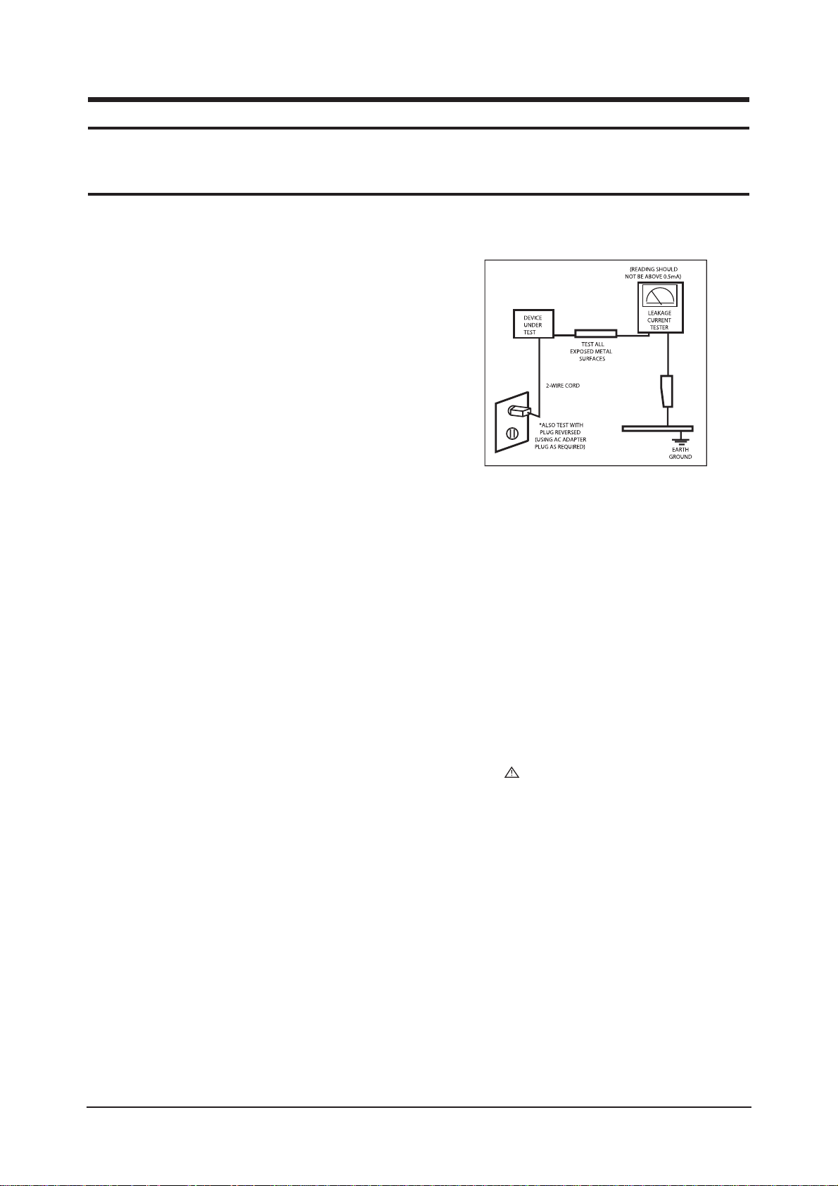
3. Leakage Current Hot Check (Figure 1-1):
WARNING : Do not use an isolation
transformer during this test.
Use a leakage current tester or a metering system that
complies with American National Standards Institute
(ANSI C101.1, Leakage Current for Appliances), and
Underwriters Laboratories (UL Publication UL1410,
59.7).
Figure 1-1. Leakage Current Test Circuit
4. With the unit completely reassembled, plug the AC line
cord directly into a 120V AC outlet. With the unit’s AC
switch first in the ON position and then OFF, measure
the current between a known earth ground (metal water
pipe, conduit, etc.) and all exposed metal parts,
including: metal cabinets, screwheads and control shafts.
The current measured should not exceed 0.5 milliamp.
Reverse the power-plug prongs in the AC outlet and
repeat the test.
1-1-4 Product Safety Notices
Some electrical and mechanical parts have special safetyrelated characteristics which are often not evident from visual
inspection. The protection they give may not be obtained by
replacing them with components rated for higher voltage,
wattage, etc. Parts that have special safety characteristics are
identified by on schematics and parts lists. A substitute
replacement that does not have the same safety characteristics
as the recommended replacement part might create shock, fire
and/or other hazards. Product safety is under review
continuously and new instructions are issued whenever
appropriate.
1 Precautions
Follow these safety, servicing and ESD precautions to prevent damage and to protect against potential hazards such as electrical shock.
1-1 Safety Precautions

1 Precautions
1-2
1-2-1 General Ser vicing
Precautions
1. Always unplug the unit’s AC power cord from the AC
power source and disconnect the DC Power Jack before
attempting to:
(a) remove or reinstall any component or assembly, (b)
disconnect PCB plugs or connectors, (c) connect a test
component in parallel with an electrolytic capacitor.
2. Some components are raised above the printed circuit
board for safety. An insulation tube or tape is sometimes
used. The internal wiring is sometimes clamped to
prevent contact with thermally hot components. Reinstall
all such elements to their original position.
3. After servicing, always check that the screws,
components and wiring have been correctly reinstalled.
Make sure that the area around the serviced part has not
been damaged.
1. Immediately before handling any semiconductor
components or assemblies, drain the electrostatic charge
from your body by touching a known earth ground.
Alternatively, wear a discharging wrist-strap device. To
avoid a shock hazard, be sure to remove the wrist strap
before applying power to the monitor.
2. After removing an ESD-equipped assembly, place it on a
conductive surface such as aluminum foil to prevent
accumulation of an electrostatic charge.
3. Do not use freon-propelled chemicals. These can
generate electrical charges sufficient to damage ESDs.
4. Use only a grounded-tip soldering iron to solder or
desolder ESDs.
5. Use only an anti-static solder removal device. Some
solder removal devices not classified as “anti-static” can
generate electrical charges sufficient to damage ESDs.
4. Check the insulation between the blades of the AC plug
and accessible conductive parts (examples: metal panels,
input terminals and earphone jacks).
5. Insulation Checking Procedure: Disconnect the power
cord from the AC source and turn the power switch ON.
Connect an insulation resistance meter (500 V) to the
blades of the AC plug.
The insulation resistance between each blade of the AC
plug and accessible conductive parts (see above) should
be greater than 1 megohm.
6. Always connect a test instrument’s ground lead to the
instrument chassis ground before connecting the positive
lead; always remove the instrument’s ground lead last.
6. Do not remove a replacement ESD from its protective
package until you are ready to install it. Most
replacement ESDs are packaged with leads that are
electrically shorted together by conductive foam,
aluminum foil or other conductive materials.
7. Immediately before removing the protective material
from the leads of a replacement ESD, touch the
protective material to the chassis or circuit assembly into
which the device will be installed.
Caution:Be sure no power is applied to the
chassis or circuit and observe all
other safety precautions.
8. Minimize body motions when handling unpackaged
replacement ESDs. Motions such as brushing clothes
together, or lifting your foot from a carpeted floor can
generate enough static electricity to damage an ESD.
1-3
Electrostatically Sensitive Devices (ESD) Precautions
Some semiconductor (solid state) devices can be easily damaged by static electricity. Such components are commonly called
Electrostatically Sensitive Devices (ESD). Examples of typical ESD are integrated circuits and some field-effect transistors. The
following techniques will reduce the incidence of component damage caused by static electricity.
1-2 Ser vicing Precautions
WARNING: An electrolytic capacitor installed with the wrong polarity might explode.
Caution: Before servicing units covered by this service manual, read and follow the Safety Precautions section
of this manual.
Note: If unforeseen circumstances create conflict between the following servicing precautions and any of the safety
precautions, always follow the safety precautions.

1 Precautions
1-3
1-4 Installation Precautions
1. For safety reasons, more than two people are
required for carrying the product.
2. Keep the power cord away from any heat emitting
devices, as a melted covering may cause fire or
electric shock.
3. Do not place the product in areas with poor
ventilation such as a bookshelf or closet. The
increased internal temperature may cause fire.
4. Bend the external antenna cable when connecting
it to the product. This is a measure to protect it
from being exposed to moisture. Otherwise, it
may cause a fire or electric shock.
5. Make sure to turn the power off and unplug the
power cord from the outlet before repositioning
the product. Also check the antenna cable or the
external connectors if they are fully unplugged.
Damage to the cord may cause fire or electric
shock.
6. Keep the antenna far away from any high-voltage
cables and install it firmly. Contact with the highvoltage
cable or the antenna falling over may
cause fire or electric shock.
7. When installing the product, leave enough space
(10cm) between the product and the wall for
ventilation purposes.
A rise in temperature within the product may cause fire.

1 Precautions
1-4
Memo

2 Product Specifications
2-1
2 Product Specifications
2-1 Fashion Feature
- RF, DVI-D, PC(Analog), 2Scart, Component, Video, S-Video
- Brightness : 500cd/
- Contrast Ratio :
23": 800:1, 27": 1000:1, 32": 800:1
- Respense time : 16ms
- Dynamic contrast
- PIP (on PC only)

2 Product Specifications
2-2
2-2 Specifications
2-2-1 LE23T51B Specifications
LCD Panel
TFT-LCD panel, RGB vertical stripe, normaly white, 23-Inch viewable, 0.372 (H) x 0.372(V)mm pixel pitch
Scanning Frequency Horizontal : 30 kHz ~ 61 kHz (Automatic)
Vertical : 60 Hz ~ 75 Hz (Automatic)
Display Colors 16.7 Million colors
Maximum Resolution Horizontal : 1360 Pixels
Vertical : 768 Pixels
Input Video Signal Analog 0.7 Vp-p
5% positive at 75 , internally terminated
Input Sync Signal Type : Seperate H/V
Level : TTL level
Maximum Pixel Clock rate
80 MHz
Active Display
Horizontal/Vertical
AC power voltage & Frequency
AC 220 ~ 240 V, 50~60 Hz
Power Consumption < 100W ( < 2W, stand by )
Dimensions(W x D x H)
Set 26.61 x 3.35 x 15.49 inches(675.9 x 85.0 x 393.4 mm) Body
26.61 x 8.02 x 17.30 inches (675.9 x 203.8 x 439.5 mm) With stand
Weight
Set(With stand) 16.76 lbs (7.6Kg)
Environmental Considerations
Operating Temperature : 50 F ~ 104 F (10 C ~ 40 C)
Operating Humidity : 10 % ~ 80 %
Storage Temperature : -4 F ~ 113 F (-20 C ~ 45 C)
Storage Humidity : 5 % ~ 95 %
TV System
Antena Input
75
- MAX Internal speaker Out : Right => 3W, Left => 3W
Sound Characteristic
- BASS Control Range : -8 dB ~ + 8dB
- TREBLE Control Range : -8 dB ~ +8 dB
- Headphone Out : 10 mW MAX
- Output Frequency : RF : 80 Hz ~ 15 kHz
A/V : 80 Hz ~ 20 kHz
System
PAL, SECAM-B/G, D/K, I, I/I, L/L, NTPB (AV3.58, 4.43)
Item
Description
508.125 mm / 285.696 mm
Tunning Frequency Synthesize
Sound BG, DK, I, L ( A2/NICAM )

2 Product Specifications
2-3
2-2-2 LE27T51B Specifications
LCD Panel
TFT-LCD panel, RGB vertical stripe, normaly white, 27-Inch viewable, 0.1460 (H) x 0.4365(V)mm pixel pitch
Scanning Frequency Horizontal : 30 kHz ~ 61 kHz (Automatic)
Vertical : 60 Hz ~ 75 Hz (Automatic)
Display Colors 16.7 Million colors
Maximum Resolution Horizontal : 1360 Pixels
Vertical : 768 Pixels
Input Video Signal Analog 0.7 Vp-p
5% positive at 75 internally terminated
Input Sync Signal Type : Seperate H/V
Level : TTL level
Maximum Pixel Clock rate
80 MHz
Active Display
Horizontal/Vertical
AC power voltage & Frequency
AC 220 ~ 240 V, 50~60 Hz
Power Consumption < 140W ( < 2W, stand by )
Dimensions(W x D x H)
Set 30.18 x 3.78 x 18.07 inches (766.5 x 96.0 x 459.0 mm) Body
30.18 x 6.02 x 19.90 inches (766.5 x 203.8 x 505.5 mm) With stand
Weight
Set(With stand) 26.46 lbs (12.0 kg)
Environmental Considerations
Operating Temperature : 50 F ~ 104 F (10 C ~ 40 C)
Operating Humidity : 10 % ~ 80 %
Storage Temperature : -4
F ~ 113 F (-20 C ~ 45 C)
Storage Humidity : 5 % ~ 95 %
TV System
Antena Input
75
- MAX Internal speaker Out : Right => 5W, Left => 5W
Sound Characteristic
- BASS Control Range : -8 dB ~ + 8dB
- TREBLE Control Range : -8 dB ~ +8 dB
- Headphone Out : 10 mW MAX
- Output Frequency : RF : 80 Hz ~ 15 kHz
A/V : 80 Hz ~ 20 kHz
System
PAL, SECAM-B/G, D/K, I, I/I, L/L, NTPB (AV3.58, 4.43)
Item
Description
596.259 mm / 335.232 mm
Tunning Frequency Synthesize
Sound BG, DK, I, L ( A2/NICAM )

2 Product Specifications
2-4
2-2-3 LE32T51B Specifications
LCD Panel
TFT-LCD panel, RGB vertical stripe, normaly white, 32-Inch viewable, 0.511 (H) x 0.511(V)mm pixel pitch
Scanning Frequency Horizontal : 30 kHz ~ 61 kHz (Automatic)
Vertical : 60 Hz ~ 75 Hz (Automatic)
Display Colors 16.7 Million colors
Maximum Resolution Horizontal : 1360 Pixels
Vertical : 768 Pixels
Input Video Signal Analog 0.7 Vp-p
5% positive at 75 , internally terminated
Input Sync Signal Type : Seperate H/V
Level : TTL level
Maximum Pixel Clock rate
80 MHz
Active Display
Horizontal/Vertical
AC power voltage & Frequency
AC 220 ~ 240 V, 50~60 Hz
Power Consumption < 170 W ( < 2W, stand by )
Dimensions(W x D x H)
Set 36.00 x 4.09 x 20.82 inches (914.5 x 104.0 x 528.8 mm) With stand
36.00 x 9.74 x 23.29 inches (914.5 x 247.5 x 591.5 mm) Body
Weight
Set(With Stand) 33.07 Ibs (15.0 Kg)
Environmental Considerations
Operating Temperature : 50 F~ 104 F (10 C ~ 40 C)
Operating Humidity : 10 % ~ 80 %
Storage Temperature : -4
F ~ 113 F (-20 C ~ 45 C)
Storage Humidity : 5 % ~ 95 %
TV System
Antena Input 75
- MAX Internal speaker Out : Right => 7.5W, Left => 7.5W
Sound Characteristic
- BASS Control Range : -8 dB ~ + 8dB
- TREBLE Control Range : -8 dB ~ +8 dB
- Headphone Out : 10 mW MAX
- Output Frequency : RF : 80 Hz ~ 15 kHz
A/V : 80 Hz ~ 20 kHz
System
PAL, SECAM-B/G, D/K, I, I/I, L/L, NTPB (AV3.58, 4.43)
Item
Description
697.69 mm / 392.26 mm
Tunning Frequency Synthesize
Sound BG, DK, I, L ( A2/NICAM )

2 Product Specifications
2-5
2-2-4 Spec Comparison
LE23T51B / LE27T51B / LE32T51B
Model
Design
Frequency
Horizontal
Vertical
Display Color
30 ~ 61 kHz
60 ~ 75 Hz
16,777,216 colors
30 ~ 61 kHz
60 ~ 75 Hz
16,777,216 colors
PC Resolution
Maximum mode
Input Signal
Sync Signal
Video Signal
Power
Consumption
Normal
Power Saving
100W / 140W / 170W
< 2W
100W / 140W / 170W
< 1W
H/V Separate, TTL, P. or N.
0.7 Vp-p @ 75ohm
H/V Separate, TTL, P. or N.
0.7 Vp-p @ 75ohm
1360 x 768 / 60 Hz 1360 x 768 / 60 Hz
Input source
Difference
DVI-D HDMI
PIP
PIP(PC Only) PIP, POP
Sound
3W / 5W / 7.5W 3W / 5W / 10W
LE23R41B / LE26R41B / LE32R41BX

2 Product Specifications
2-6
Item Item Name
Remote Control &
Batteries (AAA x 2)
Power Cord
Cover-Bottom
Stand
Stand Screw (4 ea)
Owner's Instructions
BN59-00488A
3903-000042
BN63-02177A
23, 27" : BN96-02639A
32" : BN96-02633A
6002-001294
BN68-00860C
Code.No Remark
2-3 Option Specification

3 Alignments and Adjustments
3-1
3 Alignments and Adjustments
3-1 General Alignment Instuction
1. Usually, a color LCD-TV needs only slight touch-up adjustment upon installation.
Check the basic characteristics such as height, horizontal and vertical sync.
2. Use the specified test equipment or its equivalent.
3. Correct impedance matching is essential.
4. Avoid overload. Excessive signal from a sweep generator might overload the front-end
of the TV. When inserting signal markers, do not allow the marker generator to distort test result.
5. Connect the TV only to an AC power source with voltage and frequency as specified on
the backcover nameplate.
6. Do not attempt to connect or disconnect any wire while the TV is turned on. Make sure
that the power cord is disconnected before replacing any parts.
7. To protect aganist shock hazard, use an isolation transform.

3 Alignments and Adjustments
3-2
3-2 Factory Mode Adjustments
3-2-1 Entering Factory Mode
To enter 'Service Mode' Press the remote -control keys in this sequence :
- If you do not have Factory remote - control
Power OFF MENU MUTE Power OnINFO
3-2-2 Panel Check
- Specially for LE32T51BX, You have to check Panel Maker Because of different adjustments as follows.
First of all, Check the label rating!
1) Label Rating File
* If not printed you could consider S(sec) panel mark.
2) If Panel Mark is "S", Set the factory mode indicating as follows.
* Option Byte
1. Panel Option : 32" AMLCD
If Panel Mark is "A", Set the factory mode indicating as follows.
* Option Byte
1. Panel Option : 32" AUO
Others are same shown below.
LCD PANEL
MARK

3 Alignments and Adjustments
3-3
1. Calibration : W/B Calibration
AV Calibration
DTV Calibration
PC Calibration
2. Option byte : Setting option
Panel option : 23" AMLCD, 27" CMO,
32" AUO, 32" AMLCD
Gamma
:
on/off
Auto Power : on/off
Video Mute : 5
Language : English
Hotel Mode : off/on
LNA Plus : off/on
V-chip : off
Auto FM : off/on
High Deviation : off/on
TTX List : Flop/List
MCC : off/on
TTX Group :
User OSD
DVI : on/off
3. W/B : Adjustment White Balance
Sub Bright : 128
R off set : 128
G off set : 128
B off set : 128
Sub contrast : 128
R gain : 128
G gain : 128
B gain : 128
4.
VCTi
:
VCTi IC Correct register
VCTi Page 1
VCTi Page 2
3-2-3 Factory Mode Tree
- If you have Factory remote - control
[INFO] -> [FACTORY]
1. Calibration
2. Option Byte
3. W/B
4. VCTi
5. YC Delay
6. FLI5961
7. Adjust
8. Test Pattern
9. Password
10. Check Sum
11. Spread Spectrum
12. HDCP
13. Reset
T-TRNPEU-0000 month day year time
P-TRNPEU-0000
Panel On Time(Hour) 0000
3 Alignments and Adjustments
3-4
1. Calibration
2. Option Byte
3. W/B
4. VCTi
5. YC Delay
6. FLI5961
7. Adjust
8. Test Pattern
9. Chip Debugger
10. Check Sum
11. Spread Spectrum
12. HDCP
13. Reset
T-TRNPEU-0000 month day year time
P-TRNPEU-0000
Panel On Time(Hour) 0000
5. YC Delay
RF PAL-B/G : 5
RF PAL-D/K : 6
RF PAL-I : 5
RF PAL-L/L' : 5
RF SECAM-B/G : 2
RF SECAM-D/K : 0
RF SECAM-I : 2
RF SECAM-L/L' : 5
RF NTSC 3.58 : 5
RF NTSC 4.43 : 5
AV PAL : 5
AV SECAM : 2
AV NTSC 3.58 : 5
AV NTSC 4.43 : 5
AV PAL 60 : 5
6. FLI5961 : Scaler IC Correct register
Component Calibration
: Result DTV Calibration
PC Calibration : Result PC Calibration
ACC/ACM
TNR
Picture Enhance
7. Adjust
User Control lnitial
LNA PLUS
Hotel Option
11. Spread Spectrum
Spread Spectrum
: on/off
Spread Spectrum Range
: 2
Step : 63
8. Test Pattern : VCTi IC'S own test patterns.
(Total 7 patterns)
10. Check Sum : 0000
12. HDCP : 0000
13. Reset
9. Password : Use IC Register Correction.
3 Alignments and Adjustments
3-5
3-3 White Balance - Calibr ation
3-3-2 White Balance - Adjustment
3-3-1 White Balance -Calibration
3-3-3 Conditions for Measurement
1. Calibration
DTV Calibration
PC Calibration
(Calibration Condition refer to next page)
3. W/B
(low light) (hight light)
1. On the basis of toshiba ABL pattern : High Light level (57 IRE)
- INPUT SIGNAL GENERATOR : MSPG-925LTH
* Mode NO 1 : 744X484@60 Hz
NO 6 : 1280X720@60 Hz (Component 720P)
NO 21 : 1024X768@60 Hz
*
Pattern
NO 15 : Color bar
NO 16 : Toshiba ABL Pattern
NO 17 : 16 gray
2. Optical measuring device : CA210 (FL)
Please use the MSPG-925 LTH generator for model LNR2355W,LNR2755W,LNR3255W.
(W/B adjustment Condition refer next page)
Sub Bright Sub Contrast
R offset R gain
G offset G gain
B offset B gain

3 Alignments and Adjustments
3-6
2. Adjust the white balance of AV, Component and DVI Modes.
a) Set the input to the mode in which the adjustment will be made (AV Component DVI).
* Input signal - VIDEO Mode : Model #1 (744*484 Mode), Pattern #16
- Component, DVI Mode : Model #6 (1280*720 Mode), Pattern #16
b) Enter factory W/B.
c) Adjust the low light.
- Adjust sub - Brightness to set the 'Y' value.
- Adjust red offset ('x') and blue offset ('y') to the color coordinates. ( x : 263, y : 267, Y : 1.3 ft)
* Do not adjust green offset data.
3-3-4 Method of Adjustment
1. Adjust the basic level of Component and PC input signals.
a) Set the input to the mode in which the adjustment will be made (Component PC ).
* Input signal - Component Mode : Model #6 (1280*720 Mode), Pattern #15 (picture 4-1)
- PC Mode : Model #21 (1024*768 Mode), Pattern #17 (Picture 4-2)
b) Enter factory Calibration (DTV, PC Mode Only).
* DTV Calibration Source change for PC PC Calibration
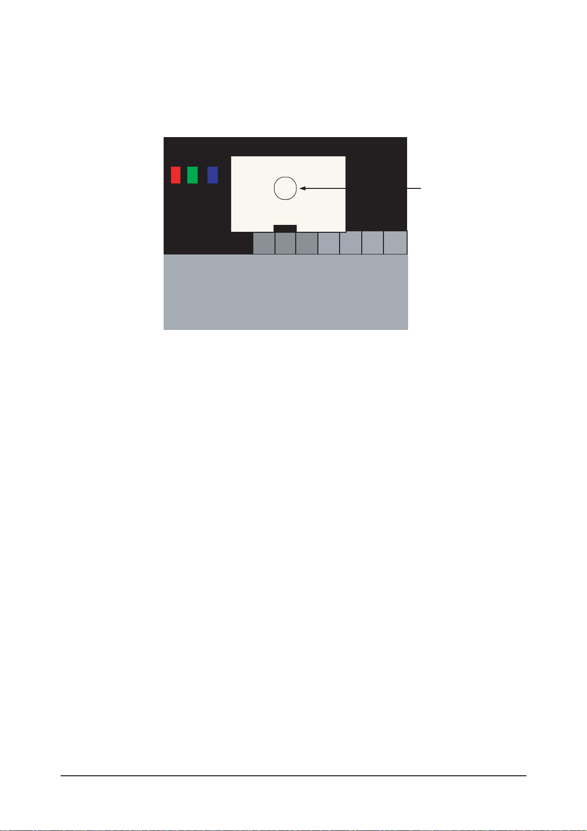
Picture 4-1 Color bar Picture 4-2 16gray
Picture 4-3 Toshiba ABL Pattern
Low light
Measurement point
3 Alignments and Adjustments
3-7
Picture 4-4 Toshiba ABL Pattern
High light
Measurement point
d) Adjust the high light. (Refer to table 1, 2 in adjustment position by mode)
- Adjust red gain ('x') and blue gain ('y') to the color coordinates. ( x : 263, y : 267 )
*
Do not adjust the green gain and sub-contrast (Y) data.
*
(Only RE32T51BX) If Panel is AM-LCD, Y adjust 36FT/L.
3 Alignments and Adjustments
3-8
3-4 TORINO Micom Update
3-4-1 Installing G-Probe
1. Uncompress GProbe5.1.0.18.zip.
2. Run GProbe5.1.0.18.exe.
3. The files are created in the C:
Program Files Genesis Microchip GProbe 5 folder.
4. Copy the ispoak_spi.hex file to the C: Program Files Genesis Microchip GProbe 5 folder.
5. Uncompress FLI5961-AC_GProbe_S0006-CSC-33B.zip.
6. Three files are extracted (FLI5961.Chip.GProbe, FLI5961.chm).
7. Copy all 2 files to the C:
Program Files
Genesis Microchip GProbe 5 ChipDB folder.
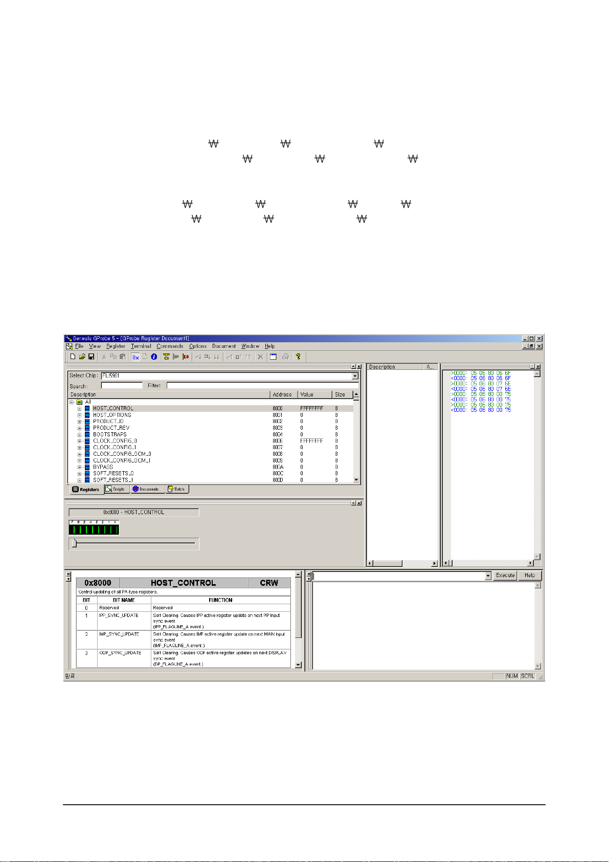
8. Run GProbe.exe in the C: Program Files Genesis Microchip GProbe 5 folder. The G-Probe program
is created.
<The screen that appears when G-Probe is successfully installed>
3 Alignments and Adjustments
3-9
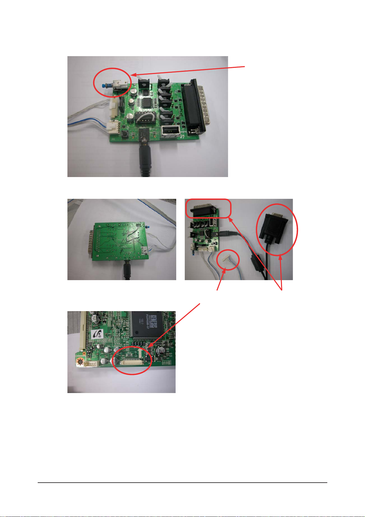
3-4-2 Connecting to the MAIN PCB
Switch off
<Bottom Side>
Connect to the PC
Connect to the MAIN PCB.
<Micom Download Jig Top Side: Note the direction of the switch>

3 Alignments and Adjustments
3-10
3-4-3 Update Procedures
1. Open mgm.txt in the C:
Program Files Genesis Microchip GProbe 5 folder.
2. The following result will appear.
//
// Batch file to program a sPI serial flash using ISP.
// Moving the stack to high memory area is now taken care of in IROM
// through the "Reset 0" command. Assumes the ISP driver is in the same
// directory as this file. Change ISP driver path in "fastFlashWrite"
// command, if different from current directory.
//
debugon
SetBuffer 0x2000 0x800
delay 200
Reset 0
delay 500
// SPI flash driver
RAMWrite ispoak_spi.hex
Run 0x500
delay 100
// Optional - Get Flash ID. The second parameter is a don't care
//FLASHCRC 0xff0000 0x20000
// Command delay for flash erase
SetDelay 1000 9000
FlashErase
// Command delay for flash write. This is for each flash write packet (upto 4 k Bytes)
SetDelay 1000 3000
// Change this line to point to a file in a different location, if needed
//fastFlashWrite C: Proj OAK APP-59xx debug obj 59xx_proj.hex
fastFlashWrite C: Program Files Genesis Microchip GProbe 5 T_TRNNUS.hex
// Optional - Get CRC of 128 kByte flash. For other sizes, change second parameter
// accordingly
//FLASHCRC 0x80000 0x20000
// to reset the monitor after programming the flash using DDC2BI ONLY:
// Un-comment the following three lines (PLEASE - FOR DDC2BI PORT SELECTED ONLY)
//0x8000=1
//0x8003=0
//0x8027=1

3 Alignments and Adjustments
3-11
The Micom program is to be copied to the folder marked in red and the name of the program is to be the
same as the file name marked in blue.
(If the Micom program is not in the folder marked in red, change the path to the folder which includes the
Micom program and then save the file.)
3. When completing all the procedures above, connect the Jig and the PCB, and run the G-Probe program.
After that
Enter 'test 10' as shown in the following figure and press Enter or click the Execute button.
If the result appears as shown in the following figure, it is properly connected.
3 Alignments and Adjustments
3-12
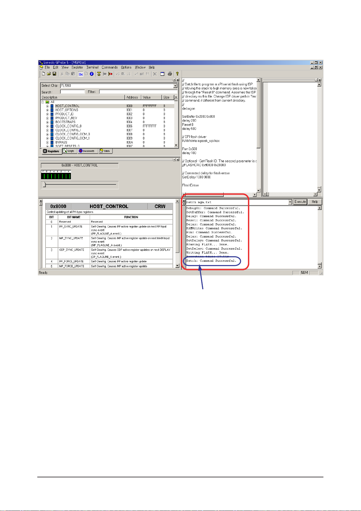
4. Enter 'batch mgm.txt' as show in the following figure and press Enter or click the Execute button to
update Micom.
If the MICOM update is successfully completed, the
above message appears.

4 Troubleshooting
4-1
4 Troubleshooting
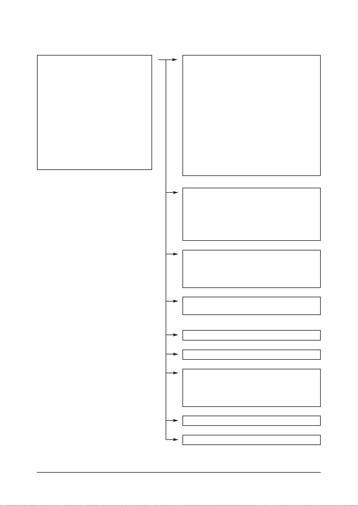
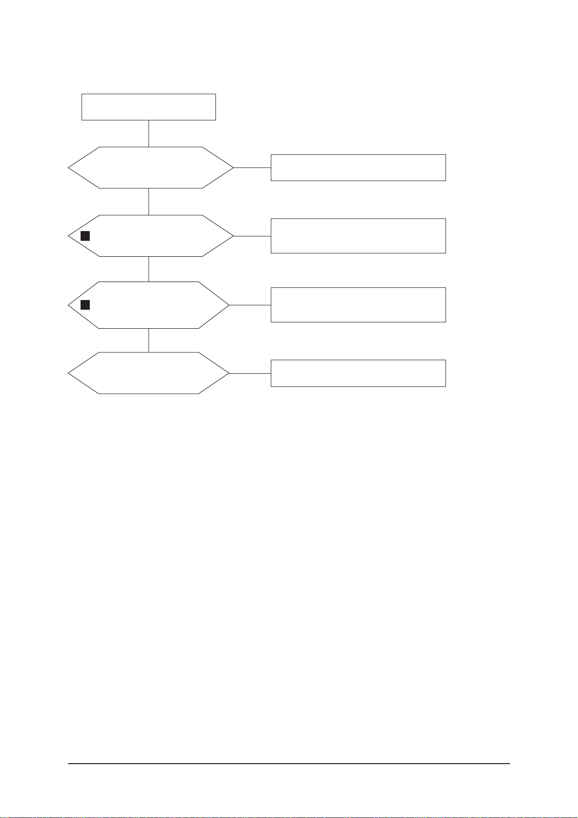
4-1 No Power
Does proper DC 12V
appear at C820, C823?
Change a Assy PCB Power.
Yes
Yes
No
Check a connection a power cable.
No
Does proper DC A3.3V,
A5V appear at
C834, C830?
Check a IC816, IC815
Change a main PCB ass'y.
Yes
No
Does proper DC 5V, 3.3V,
1.8V appear at C813, C811,
C816?
Check a IC821, IC811
Change a main PCB ass'y.
Yes
A power is supplied to set?
Check a other function.
(No picture part)
Replace a lcd panel.
No
No
LAMP off, power indicator
LED red color?
4 Troubleshooting
4-2
4-2 No Video (Analog PC Signal)
Check a PC source and check
the connection of DSUB cable?
Input a analog PC signal and
connected cable(DPMS).
Yes
Does the signal appear at
R781, R782, R783?
PC cable. Change a PC
cable. Change a main PCB ass'y.
Yes
Does the digital data appear
at output of
LVDS TX(R422~R425,
R430~R433)?
Check a IC310.
Change a main PCB ass'y.
Yes
Check a LVDS cable?
Replace a lcd panel?
Please, Call to Samsung Co. LTD.
Yes
Power Indicator is off.
Lamp on, no video.
No
No
No
No
1
3
4 Troubleshooting
4-3
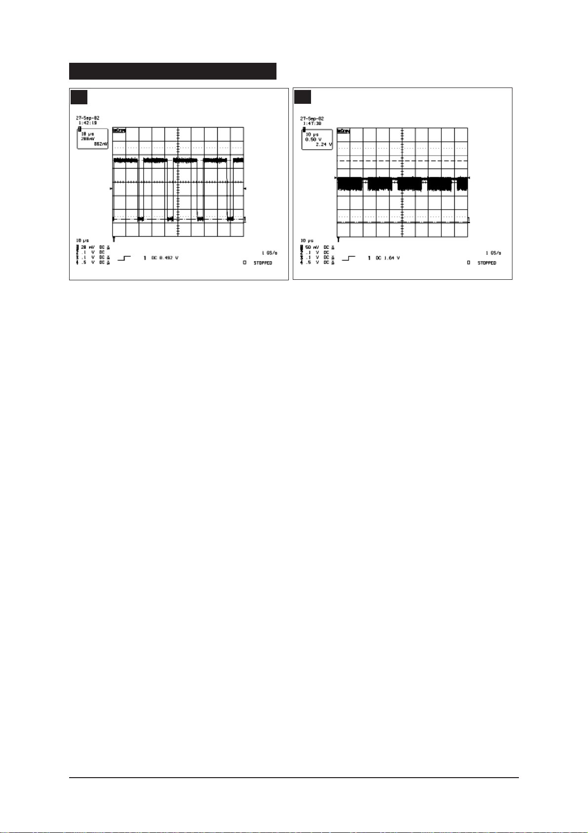
WAVEFORMS
1
R,G,B Output Signal
3
Digital Output Data of IC310
4 Troubleshooting
4-4
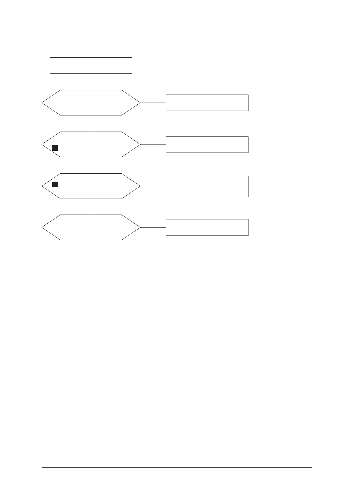
4-3 No Video (DVI-Digital Signal)
Check the connectionn
of HDMI cable?
Input a HDMI cable.
Yes
Does the digital data appear at
FT2704, 2705, 2706, 2708?
HDMI cable change a HDMI cable
change a main PCB ass'y.
Yes
Does the digital data
appear at output of IC310
LVDS(R422~R425, R430~R433)?
Check a IC310.
Change a main PCB ass'y.
Yes
Check a LVDS cable?
Replacea lcd panel?
Please, Call to Samsung Co. LTD.
Yes
Power Indicator is off.
Lamp on, no video.
No
No
No
No
4
3
 Loading...