

Samsung KS58015N, KS58015D Datasheet

KS58015 DTMF DIALER FOR BINARY DATA-IN
ORDERING INFORMATION
INTRODUCTION
The KS58015 is a DTMF dialer for 4 bit binary data input from
microprocessor. When the tone enable input low, the oscillator is inhibited and the device is in a low power consumption at standby mode.
On the low to high transition of tone enable, data is latched into the
device and selected the standard DTMF signals.
The N-channel open drain output provides a MUTE output during tone
generation.
FEATURES
• Direct interface with microprocessor
• Generates 16 standard tones
• Uses inexpensive TV crystal or ceramic resonator
(3.579545MHz)
• Very low total harmonic distortion
• Low power standby mode
• Binary data inputs with latches
• Wide Operating Voltage : 2.5 ~ 8.0V
KS58015N
KS58015D
BLOCK DIAGRAM
V
DD
OSC IN
OSC OUT
OSC
14-DIP-300
14-SOP-225B
Device Package Operating Temperature
14-DIP-300
14-SOP-225B
- 30°C ~ + 70°C
MUTE
MUTE LOGIC
TEN
ST
CONTROL
CIRCUIT
ROW & COLUMN
TONE COUNTER
GS
D0
D1
D2
DATA
LATCH &
DECODER
4
D/A
CONVERTER &
MIXING
TONE OUT
D3
SS
V
Fig.1
KS58015 DTMF DIALER FOR BINARY DATA-IN
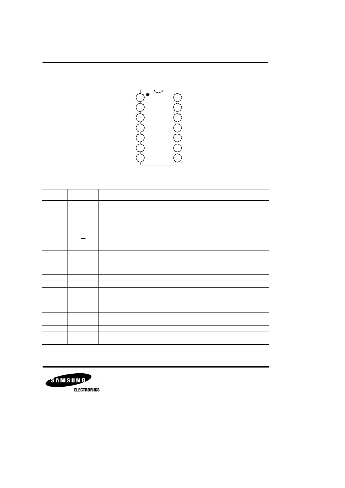
PIN CONFIGURATION
1
VDD
2
TEN
3
ST
4
GS
V
SS
OSC IN
OSC OUT MUTE
KS58015
5
6
7 8
14
13
12
11
10
9
Fig. 2
PIN DESCRIPTION
Pin No Symbol Descriptions
1 V
DD
2 TEN
3 ST
4 GS
5 V
SS
6 OSC IN Oscillator input
7 OSC OUT Oscillator output
8 MUTE
9, 10,
11, 12
D0, D1,
D2, D3
13 N.C No connection.
14 Tone out
Positive supply input
Tone enable input. An internal pull-up resistor is in a chip. When this pin connects to
logic ‘low’, the oscillator is inhibited and the tone generators and output transistor are
turned off. A low to high transition on this pin latches in data from D0 ~ D3, and tone
generation continues until this pin is connected ‘low’ again.
Single tone enable. An internal pull-up resistor is in a chip. When this pin connects
to logic ‘low’, the device is in a single tone mode. For normal operation, connects this
pin to VDD or open-circuit.
Group selection input. This pin is used to select the high group or low group frequency, when the device is in single tone mode. An internal pull-up resistor is in a
chip. When this pin connects to VDD or open, the high group will be generated, and when
connects to VSS, the low group will be generated.
Negative supply input
N-channel open drain output.
This pin is a logic high state, when the tone enable pin is a high state.
This pin goes a logic low state, when the tone enable pin is a low state.
DATA-INPUTS. These are the inputs for binary-coded data, which is latched in on
the rising edge of the tone enable signal.
This output is the open emitter of a NPN transistor. When an external load resistor
is connected from this pin to VSS, the tone generates on the tone enable pin = ‘High’.
TONE OUT
NC
D3
D2
D1
D0
 Loading...