


User manual
HW-J8500R
HW-J8501R
Imagine the possibilities
Thank you for purchasing this Samsung product.
To receive more complete service, please register your product at
www.samsung.com/register

GETTING STARTED
GETTING STARTED
SAFETY INFORMATION
SAFETY WARNINGS
TO REDUCE THE RISK OF ELECTRIC SHOCK, DO NOT REMOVE THE COVER (OR BACK).
NO USER-SERVICEABLE PARTS ARE INSIDE. REFER SERVICING TO QUALIFIED SERVICE PERSONNEL.
This symbol indicates that high voltage is
CAUTION
RISK OF ELECTRIC SHOCK.
DO NOT OPEN.
Class II product : This symbol indicates that it does not require a safety connection to electrical
earth (ground).
AC voltage : This symbol indicates that the rated voltage marked with the symbol is AC voltage.
DC voltage : This symbol indicates that the rated voltage marked with the symbol is DC voltage.
Caution, Consult instructions for use : This symbol instructs the user to consult the user manual for
further safety related information.
WARNING : To reduce the risk of fire or electric shock, do not expose this appliance to rain or moisture.
CAUTION : TO PREVENT ELECTRIC SHOCK, MATCH WIDE BLADE OF PLUG TO WIDE SLOT, FULLY INSERT.
• This apparatus shall always be connected to a AC outlet with a protective grounding connection.
• To disconnect the apparatus from the mains, the plug must be pulled out from the mains socket, therefore the mains plug shall be
readily operable.
CAUTION
• Do not expose this apparatus to dripping or splashing. Do not put objects filled with liquids, such as vases on the apparatus.
• To turn this apparatus off completely, you must pull the power plug out of the wall socket. Consequently, the power plug must be
easily and readily accessible at all times.
Wiring the Main Power Supply Plug (UK Only)
IMPORTANT NOTICE
The mains lead on this equipment is supplied with a moulded plug incorporating a fuse. The value of the fuse is
indicated on the pin face of the plug and if it requires replacing, a fuse approved to BS1362 of the same rating must
be used. Never use the plug with the fuse cover removed. If the cover is detachable and a replacement is required,
it must be of the same colour as the fuse fitted in the plug. Replacement covers are available from your dealer. If the
fitted plug is not suitable for the power points in your house or the cable is not long enough to reach a power point,
you should obtain a suitable safety approved extension lead or consult your dealer for assistance. However, if there is
no alternative to cutting off the plug, remove the fuse and then safely dispose of the plug. Do not connect the plug to a
mains socket as there is a risk of shock hazard from the bared flexible cord. Never attempt to insert bare wires directly
into a mains socket. A plug and fuse must be used at all times.
IMPORTANT
The wires in the mains lead are coloured in accordance with the following code:– BLUE = NEUTRAL BROWN = LIVE
As these colours may not correspond to the coloured markings identifying the terminals in your plug, proceed as
follows:– The wire coloured BLUE must be connected to the terminal marked with the letter N or coloured BLUE or
BLACK. The wire coloured BROWN must be connected to the terminal marked with the letter L or coloured BROWN
or RED.
WARNING : DO NOT CONNECT EITHER WIRE TO THE EARTH TERMINAL WHICH IS MARKED WITH THE
LETTER E OR BY THE EARTH SYMBOL , OR COLOURED GREEN OR GREEN AND YELLOW.
present inside. It is dangerous to make any kind
of contact with any internal part of this product.
This symbol indicates that important literature
concerning operation and maintenance has
been included with this product.
2
GETTING STARTED
99.1mm 99.1mm
68.6
mm
99.1mm
PRECAUTIONS
Ensure that the AC power supply in your house complies with the power requirements listed on the identification sticker
located on the back of your product. Install your product horizontally, on a suitable base (furniture), with enough space
around it for ventilation (7~10 cm). Make sure the ventilation slots are not covered. Do not place the unit on amplifiers or
other equipment which may become hot. This unit is designed for continuous use. To fully turn off the unit, disconnect
the AC plug from the wall outlet. Unplug the unit if you intend to leave it unused for a long period of time.
ENG
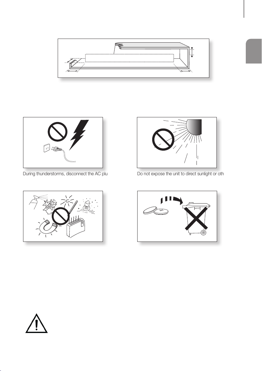
During thunderstorms, disconnect the AC plug from the
wall outlet. Voltage peaks due to lightning could damage
the unit.
Protect the product from moisture (i.e. vases), and
excess heat (e.g. a fireplace) or equipment creating
strong magnetic or electric fields. Unplug the power
cable from the AC wall socket if the unit malfunctions.
Your product is not intended for industrial use. It is for
personal use only. Condensation may occur if your
product has been stored in cold temperatures. If
transporting the unit during the winter, wait approximately
Do not expose the unit to direct sunlight or other heat
sources. This could lead to overheating and cause the
unit to malfunction.
The battery used with this product contains chemicals
that are harmful to the environment. Do not dispose of
the battery in the general household trash. Do not
expose the battery to excess heat, direct sunlight, or fire.
Do not short circuit, disassemble, or overheat the battery.
Danger of explosion if the battery is replaced incorrectly.
Replace only with the same or equivalent type.
2 hours until the unit has reached room temperature
before using.
WARNING: DO NOT INGEST BATTERY. CHEMICAL BURN HAZARD. The remote control supplied with
this product contains a coin/button cell battery. If the coin/button cell battery is swallowed, it can cause
severe internal burns in just 2 hours and can lead to death. Keep new and used batteries away from
children. If the battery compartment does not close securely, stop using the remote and make sure to
keep it away from children. If you think the battery might have been swallowed or placed inside any part of the body,
seek immediate medical attention.
3

GETTING STARTED
CONTENTS
2 GETTING STARTED
2 Safety Information
5 What’s Included
6 DESCRIPTIONS
6 Top / Front Panel
7 Rear / Bottom Panel
8 Remote Control
10 INSTALLATION
10 Installing the Soundbar
10 Installing the Wall Mount
14 Placing the Soundbar on a TV stand
15 Installing the Soundbar as a Free-Standing
Unit
16 Assembling the Clamp-Wire
16 Mounting the Cover-Feet
(4 EA) onto the Subwoofer
17 CONNECTIONS
17 Connecting the Subwoofer
19 Connecting to a TV
19 TV SoundConnect
20 Connecting to a TV Using an HDMI (Digital)
Cable
20 Connecting to a TV Using a Digital Optical
Cable
21 Connecting to External Devices
21 HDMI Cable
22 Optical or Analogue Audio Cable
23 FUNCTIONS
23 Input Mode
24 Bluetooth
26 Using the Multiroom App
28 Using the Network Standby On
Function
29 Software Update
31 TROUBLESHOOTING
31 Troubleshooting
32 APPENDIX
32 Specifications
● Figures and illustrations in this User Manual are
provided for reference only and may differ from
actual product appearance.
● An administration fee may be charged if either
(a) an engineer is called out at your request and
there is no defect with the product (i.e. where
the user manual has not been read).
(b) you bring the unit to a repair centre and there is
no defect with the product (i.e. where the user
manual has not been read).
● You will be informed of the administration fee
amount before a technician visits.
4
WHAT’S INCLUDED
BEFORE READING THE USER’S MANUAL
Note the following terms before reading the user manual.
+ Icons used in this manual
Icon Term Definition
GETTING STARTED
ENG
Caution
Note
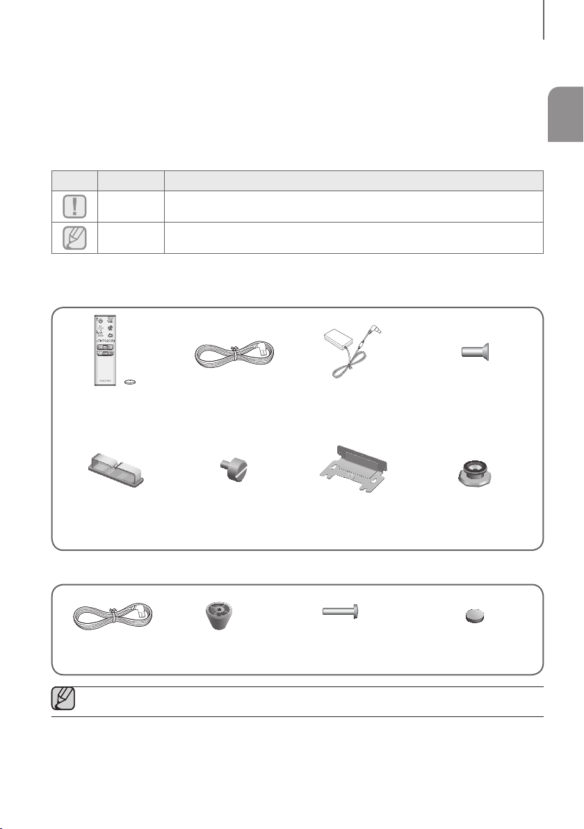
Check for the supplied accessories shown below.
Main Unit
Remote Control /
Lithium Battery (3V :
CR2032)
Clamp-Wire Holder-Fix Mount Wall-Mount Bracket
Subwoofer
Indicates a situation where a function does not operate or settings may be cancelled.
Indicates tips or instructions on the page that help you operate a function.
Power Cord AC/DC Adapter
Holder-Screw 2
: 4 EA
Holder-Screw 1
: 4 EA
Power Cord Cover-Foot : 4 EA Screw-Taptite : 4 EA Foot Rubber : 4 EA
● The appearance of the accessories may differ slightly from the illustrations above.
5
DESCRIPTIONS
DESCRIPTIONS
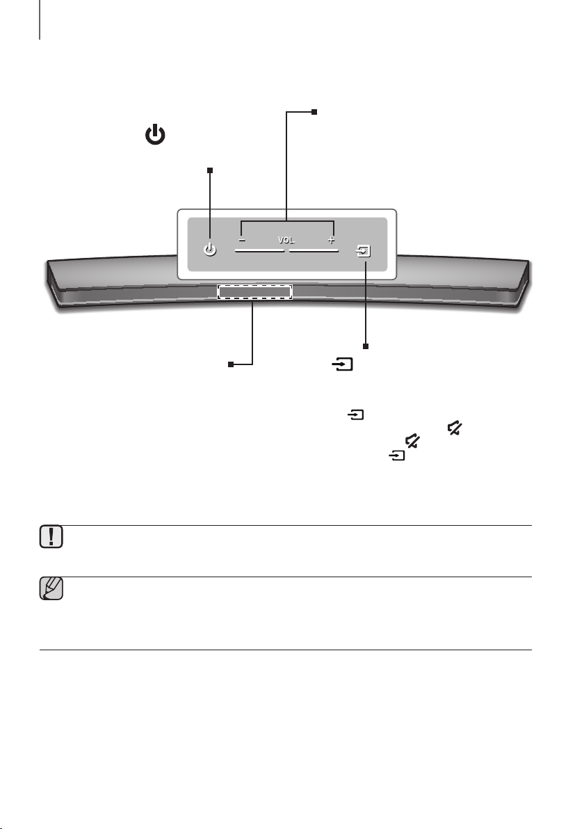
TOP / FRONT PANEL
(Power) Button
Turns the power on and off.
VOL. - / +
Controls the volume level.
The numeric value of the volume level
appears in the front panel display.
Display
Displays the current mode.
● To clean this apparatus, unplug the power cord from the wall outlet and wipe the product using a soft, dry
cloth. Due to aluminum being a positive electrostatic material, static discharge may occur.
● When you plug in the AC cord, the power button will begin working in 4 to 6 seconds.
● When you turn on this unit, there will be a 4 to 5 second delay before it produces sound.
● If you want to enjoy sound only from the Soundbar, you must turn off the TV's speakers in the Audio Setup
menu of your TV. Refer to the owner's manual supplied with your TV.
(Source) Button
Selects the D.IN, AUX, HDMI, BT, or TV input.
● While the unit is powered on, pressing the
button for more than 3 seconds sets
the button to act as the
To cancel the
press the
3 seconds again.
(Mute) button setup,
button for more than
(Mute) button.
6

REAR / BOTTOM PANEL
OPTICAL IN (D.IN)
Connect to the digital (optical) output of an external device.
HDMI OUT (TV-ARC)
Outputs digital video and audio signals simultaneously using an
Inputs digital video and audio signals simultaneously using an HDMI
cable. Use when connecting a supported external device.
Lets you connect to a network using a LAN cable.
Connect to the Analogue output of an external device.
DC 24V
SPK ADDWi-Fi SETUP
HDMI cable.
HDMI IN
LAN
AUX IN
OPTICAL IN
(TV-ARC)
HDMI OUT
LAN HDMI IN
AUX IN
SERVICE
DESCRIPTIONS
ENG
LABEL
SERVICE
SERVICE
To upgrade the product's
software through the USB
Port.
Wi-Fi SETUP
Press this button to
connect your Soundbar
to your network using
Wi-Fi setup. (Requires a
smart device and the
Samsung Multiroom app.
See page 26.)
SPK ADDWi-Fi SETUP
DC 24V
SPK ADD
Press the button to connect
the Soundbar to a Samsung
HUB (purchased separately)
or a network. (Requires a
smart device and the
Samsung Multiroom app.
See page 26.)
DC 24V
(Power Supply In)
Connect the DC power
adaptor to the power
supply jack, and then
connect the AC power
adaptor plug to a wall
outlet.
● When disconnecting the power cable of the AC power adaptor from a wall outlet, pull the plug.
Do not pull the cable.
● Do not connect this unit or other components to an AC outlet until all connections between components
are complete.
● Make sure to rest the AC/DC Adapter flat on a table or the floor. If you place the AC/DC Adapter so that it
is hanging with the AC cord input facing upwards, water or other foreign substances could enter the
Adapter and cause the Adapter to malfunction.
7

DESCRIPTIONS
REMOTE CONTROL
SOURCE
Press to select a source connected to the Soundbar.
Mute
You can turn the volume down to 0 with the push of a button.
Press again to restore the sound to the previous volume level.
Repeat
The Repeat function is available only when playing back music from Songs on phone
or DMS of Samsung Multiroom app.
OFF - REPEAT : Cancells Repeat Playback.
TRACK - REPEAT : Plays a track repeatedly.
ALL - REPEAT : Plays all tracks repeatedly.
Skip Forward
If there is more than one file on the device you are playing, and you press
]
button, the next file is selected.
the
SOUND CONTROL
Press to select TREBLE, BASS or AUDIO SYNC. Then, use the
buttons to adjust the TREBLE or BASS volume from -3 ~ +3.
Press and hold the SOUND CONTROL button for about 5 seconds to adjust
the sound for each frequency band. 150Hz, 300Hz, 600Hz, 1.2KHz, 2.5KHz,
5KHz, and 10KHz are selectable and each can be adjusted to a setting between
-6 ~ +6.
If the Soundbar is connected to a digital TV and the video appears out of sync
with the audio, press the SOUND CONTROL button to sync the audio with the
video. Use the
0 ms ~ 300 ms. In TV mode, and BT mode, the Audio Sync function may not
available.
[,]
buttons to set the audio delay between
[,]
Anynet+
Press the Anynet+ button to turn the Anynet+ function on or off.
(Default : Auto Power Link OFF, ON - ANYNET+ / OFF - POWER LINK or OFF
- ANYNET+ / ON - POWER LINK). The Anynet+ function lets you control the
Soundbar with the remote from an Anynet+ compatible Samsung TV.
The Soundbar must be connected to the TV via an HDMI cable.
* Auto Power Link
Synchronizes the Soundbar to a connected Optical source via the Optical
jack so it turns on automatically when you turn on your TV. (See page 21)
Auto Power Link function is only available in the D.IN mode.
You can also activate Wi-Fi SETUP function by pressing and holding Anynet+
button on the remote for over 7 seconds.
● Operate the TV using the TV's remote control.
8

Power
Turns the Soundbar on and off.
Volume
Adjusts the volume level of the unit.
Play / Pause
p
Press the
Press the
If there is more than one file on the device you are playing, and you press the
You can select from 6 sound modes - STANDARD (Original Sound), MUSIC,
CLEAR VOICE, SPORTS, MOVIE, and NIGHT MODE - depending on the
Select the STANDARD mode if you want to enjoy the original sound.
Surround Sound adds depth and spaciousness to the sound. Pressing the
SOUND button repeatedly cycles through the Surround Sound settings :
ON - SURROUND SOUND, OFF - SURROUND SOUND
Press STREAMING MUSIC button to listen to an Internet radio station. Each
time you press this button, the Soundbar switches to the next default station,
To use the STREAMING MUSIC function, the Soundbar must be connected to
Lets you apply dynamic range control to Dolby Digital.
Press and hold the STREAMING MUSIC button to toggle the DRC (Dynamic
Press the WOOFER button. Then, use the [,] buttons to adjust the
You can also activate SPK ADD function of the Soundbar by pressing and
holding WOOFER button of the remote for over 5 seconds.
button to pause a file temporarily.
p
button again to play the selected file.
Skip Back
button, the previous file is selected.
SOUND EFFECT
content you want to listen to.
SOUND
STREAMING MUSIC
cycling through the 3 default stations.
the Internet. (See page 28)
DRC (Dynamic Range Control) *
Range Control) function ON and OFF.
WOOFER
Subwoofer volume from -12, -6
~
+6.
[
DESCRIPTIONS
ENG
INSTALLING THE BATTERY IN THE REMOTE CONTROL
1. Use a suitable coin to turn the
remote control's battery cover
counterclockwise to remove it
as shown in the figure above.
2. Insert a 3V lithium battery. Keep the
positive (+) pole facing up when inserting
the battery. Put the battery cover on and
align the '●' marks side by side as
shown in the figure above.
9
3. Use a suitable coin to
turn the remote control
battery cover clockwise
as far as it will go to fix it
in place.

INSTALLATION
INSTALLATION
INSTALLING THE SOUNDBAR
INSTALLING THE WALL MOUNT
+ Installation Precautions
● Install on a vertical wall only.
● For the installation, avoid a location with high temperature or humidity, or a wall that cannot sustain the weight of
the set.
● Check the strength of the wall. If the wall is not strong enough to support the unit, reinforce the wall or install the
unit on a different wall that can support the unit's weight.
● Purchase and use the fixing screws or anchors appropriate for the kind of wall you have (plaster board, iron board,
wood, etc.). If possible, fix the support screws into wall studs.
● Purchase wall mounting screws according to the type and thickness of the wall you will mount the Soundbar on.
- Diameter : M5
- Length: 35 mm or longer recommended.
● Connect cables from the unit to external devices before you install it on the wall.
● Make sure the unit is turned off and unplugged before you install it. Otherwise, it may cause an electric shock.
Check for the supplied accessories shown below.
Holder-Screw 1 : 4 EA Holder-Screw 2 : 4 EA Wall-Mount Bracket Holder-Fix Mount
10

INSTALLATION
AUX IN
LAN HDMI IN
OPTICAL IN
HDMI OUT
(TV-ARC)
SERVICE
SPK ADDWi-Fi SETUP
AUX IN
LAN HDMI IN
OPTICAL IN
HDMI OUT
(TV-ARC)
SERVICE
SPK ADDWi-Fi SETUP
DC 24V
2
OPTICAL IN
(TV-ARC)
1
DC 24V
1. Place the Soundbar as shown in the illustration, ensuring that none of the buttons touch the surface it is lying on.
2. If the Holder-Foot (3 EA) and Holder-Support (2 EA) are attached, remove them.
Holder-Foot Holder-Support
HDMI OUT
LANHDMI IN
AUX IN
SPK ADDWi-Fi SETUP
SERVICE
ENG
OPTICAL IN
(TV-ARC)
HDMI OUT
LANHDMI IN
DC 24V
AUX IN
SPK ADDWi-Fi SETUP
SERVICE
3. Fix Holder-Screw 1 (4 EA) and Holder-Screw 2 (for main unit fixing) (4 EA) into the holes of the Soundbar tightly
as shown in the illustration.
11