

Samsung PS-FZ210, PS-CZ210, PS-WZ210, HT-Z210T/XAH, PS-RZ210 Service Manual
SERVICE
Manual
DIGITAL HOME THEATER SYSTEM
Refer to the service manual in the GSPN (see the rear cover) for the more information.
CONTENTS
1. Precaution
2. Product Specification
3. Disassembly & Reassembly
4. Troubleshooting
5. Exploded View & Part List
6. PCB Diagram
7. Schematic Diagram
DIGITAL HOME
THEATER SYSTEM
Model Name : HT-Z210
Model Code : HT-Z210T/XAH
Speaker HT-Z210
Front PS-FZ210
Center PS-CZ210
Rear PS-RZ210
Subwoofer PS-WZ210
HT-Z210
All manuals and user guides at all-guides.com
all-guides.com

This Service Manual is a property of Samsung Electronics
Co.,Ltd. Any unauthorized use of Manual can be punished
under applicable International and/or domestic law.
GSPN (Global Service Partner Network)
Area Web Site
North America service.samsungportal.com
Latin America latin.samsungportal.com
CIS cis.samsungportal.com
Europe europe.samsungportal.com
China china.samsungportal.com
Asia asia.samsungportal.com
Mideast & Africa mea.samsungportal.com
© Samsung Electronics Co.,Ltd. Mar. 2008
Printed in Korea
All manuals and user guides at all-guides.com
Contents
1. Precaution
1-1 Safety Precautions ...........................................................................................1-1
1-2 Servicing Precautions ......................................................................................
1-3
1-3 Precautions for Electrostatically Sensitive Devices (ESDs) .............................
1-4
2. Product Specification
2-1 Product Feature ...............................................................................................2-1
2-2 Specifications ...................................................................................................
2-2
2-3 Specifications Analysis .....................................................................................
2-4
2-4 Accessories ......................................................................................................
2-6
3. Disassembly & Reassembly
3-1 Overall Disassembly & Reassembly ................................................................3-1
4. Troubleshooting
4-1 Checkpoints by Error Mode.............................................................................. 4-2
4-2 Measures to be taken when the Protection Circuit operates ...........................
4-25
4-3 Initialization & Upgrade Methods .....................................................................
4-27
5. Exploded View & Part List
5-1 Exploded View .................................................................................................5-2
5-2 Speaker System ...............................................................................................
5-4
5-3 Electrical Part List ............................................................................................
5-5
6. PCB Diagram
6-1 Wiring Diagram ................................................................................................6-2
6-2 FRONT PCB Top ..............................................................................................
6-3
6-3 FRONT PCB Bottom ........................................................................................
6-5
6-4 AMP PCB Top ..................................................................................................
6-6
6-5 AMP PCB Bottom .............................................................................................
6-8
6-6 BLUETOOTH PCB Top ....................................................................................
6-9
6-7 BLUETOOTH PCB Bottom ..............................................................................
6-9
6-8 MAIN PCB Top .................................................................................................
6-10
6-9 MAIN PCB Bottom ...........................................................................................
6-13
6-10 SMPS PCB Top ................................................................................................
6-14
All manuals and user guides at all-guides.com
Contents
7. Schematic Diagram
7-1 Overall Block Diagram .....................................................................................7-2
7-2 FRONT .............................................................................................................
7-3
7-3 BLUETOOTH ...................................................................................................
7-4
7-4 AMP .................................................................................................................
7-5
7-5 MAIN ................................................................................................................
7-6
7-6 MICOM .............................................................................................................
7-7
7-7 ANALOG ..........................................................................................................
7-8
7-8 HDMI ................................................................................................................
7-9
7-9 SMPS ...............................................................................................................
7-10
All manuals and user guides at all-guides.com
Samsung Electronics 1-1
Precaution
1. Precaution
Follow these safety, servicing and ESD precautions to prevent damage and protect against potential hazards such
as electrical shock and X-rays.
1-1 Safety Precautions
1. Be sure that all of the built-in protective devices are replaced.
2. When reinstalling the chassis and its assemblies, be sure to restore all protective devices, including control
knobs and compartment covers.
3. Make sure that there are no cabinet openings through which people--particularly children--might insert fingers
and contact dangerous voltages. Such openings include the spacing between the picture tube and the cabinet
mask, excessively wide cabinet ventilation slots, and improperly fitted back covers.
4. Design Alteration Warning:
Never alter or add to the mechanical or electrical design of the unit.
Example: Do not add auxiliary audio or video connectors. Such alterations might create a safety hazard.
Also, any design changes or additions will void the manufacturer’s warranty.
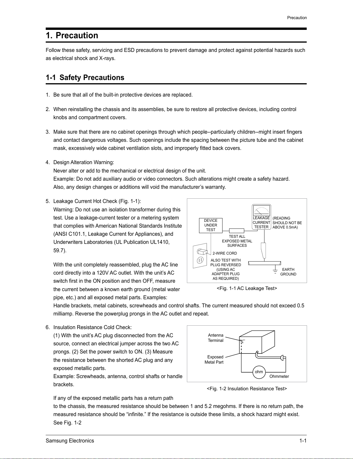
5. Leakage Current Hot Check (Fig. 1-1):
Warning: Do not use an isolation transformer during this
test. Use a leakage-current tester or a metering system
that complies with American National Standards Institute
(ANSI C101.1, Leakage Current for Appliances), and
Underwriters Laboratories (UL Publication UL1410,
59.7).
With the unit completely reassembled, plug the AC line
cord directly into a 120V AC outlet. With the unit’s AC
switch first in the ON position and then OFF, measure
the current between a known earth ground (metal water
pipe, etc.) and all exposed metal parts. Examples:
Handle brackets, metal cabinets, screwheads and control shafts. The current measured should not exceed 0.5
milliamp. Reverse the powerplug prongs in the AC outlet and repeat.
6. Insulation Resistance Cold Check:
(1) With the unit’s AC plug disconnected from the AC
source, connect an electrical jumper across the two AC
prongs. (2) Set the power switch to ON. (3) Measure
the resistance between the shorted AC plug and any
exposed metallic parts.
Example: Screwheads, antenna, control shafts or handle
brackets.
If any of the exposed metallic parts has a return path
to the chassis, the measured resistance should be between 1 and 5.2 megohms. If there is no return path, the
measured resistance should be “infinite.” If the resistance is outside these limits, a shock hazard might exist.
See Fig. 1-2
DEVICE
UNDER
TEST
LEAKAGE
CURRENT
TESTER
TEST ALL
EXPOSED METAL
SURFACES
2-WIRE CORD
ALSO TEST WITH
PLUG REVERSED
(USING AC
ADAPTER PLUG
AS REQUIRED)
EARTH
GROUND
(READING
SHOULD NOT BE
ABOVE 0.5mA)
<Fig. 1-1 AC Leakage Test>
Antenna
Terminal
ohm
<Fig. 1-2 Insulation Resistance Test>
Exposed
Metal Part
Ohmmeter
All manuals and user guides at all-guides.com
1-2 Samsung Electronics
Precaution
7. Components, parts and wiring that appear to have overheated or that are otherwise damaged should be
replaced with parts that meet the original specifications. Always determine the cause of damage or overheating,
and correct any potential hazards
8. Observe the original lead dress, especially near the following areas: Antenna wiring, sharp edges, and
especially the AC and high voltage power supplies. Always inspect for pinched, out-of-place, or frayed wiring.
Do not change the spacing between components and the printed circuit board. Check the AC power cord for
damage. Make sure that no wires or components touch thermally hot parts.
9. Product Safety Notice:
Some electrical and mechanical parts have special safety-related characteristics which might not be obvious
from visual inspection. These safety features and the protection they give might be lost if the replacement
component differs from the original--even if the replacement is rated for higher voltage, wattage, etc.
10. Components that are critical for safety are indicated in the circuit diagram by shading,
or . Use
replacement components that have the same ratings, especially for flame resistance and dielectric strength
specifications. A replacement part that does not have the same safety characteristics as the original might
create shock, fire or other hazards.
All manuals and user guides at all-guides.com
all-guides.com
Samsung Electronics 1-3
Precaution
1-2 Servicing Precautions
1. Servicing precautions are printed on the cabinet. Follow them.
2. Always unplug the unit’s AC power cord from the AC power source before attempting to: (a) Remove or reinstall
any component or assembly, (b) Disconnect an electrical plug or connector, (c) Connect a test component in
parallel with an electrolytic capacitor.
3. Some components are raised above the printed circuit board for safety. An insulation tube or tape is sometimes
used. The internal wiring may be clamped to prevent contact with thermally hot components. Reinstall all such
elements to their original position.
4. After servicing, always check that the screws, components and wiring have been correctly reinstalled.
Make sure that the portion around the serviced part has not been damaged.
5. Check the insulation between the blades of the AC plug and accessible conductive parts (examples: metal
panels, input terminals and earphone jacks).
6. Insulation Checking Procedure: Disconnect the power cord from the AC source and turn the power switch ON.
Connect an insulation resistance meter (500V) to the blades of the AC plug.
The insulation resistance between each blade of the AC plug and accessible conductive parts (see above)
should be greater than 1 megohm.
7. Never defeat any of the B+ voltage interlocks. Do not apply AC power to the unit (or any of its assemblies)
unless all solid-state heat sinks are correctly installed.
8. Always connect a test instrument’s ground lead to the instrument chassis ground before connecting the positive
lead; always remove the instrument’s ground lead last.
First read the “Safety Precautions” section of this manual. If some unforeseen circumstance
creates a conflict between the servicing and safety precautions, always follow the safety
precautions.
All manuals and user guides at all-guides.com
1-4 Samsung Electronics
Precaution
1-3 Precautions for Electrostatically Sensitive Devices (ESDs)
1. Some semiconductor (“solid state”) devices are easily damaged by static electricity.
Such components are called Electrostatically Sensitive Devices (ESDs). Examples include integrated circuits
and some field-effect transistors. The following techniques will reduce the occurrence of component damage
caused by static electricity.
2. Immediately before handling any semiconductor components or assemblies, drain the electrostatic charge from
your body by touching a known earth ground. Alternatively, wear a discharging wrist-strap device. (Be sure to
remove it prior to applying power--this is an electric shock precaution.)
3. After removing an ESD-equipped assembly, place it on a conductive surface such as aluminum foil to prevent
accumulation of electrostatic charge.
4. Do not use freon-propelled chemicals. These can generate electrical charges that damage ESDs.
5. Use only a grounded-tip soldering iron when soldering or unsoldering ESDs.
6. Use only an anti-static solder removal device. Many solder removal devices are not rated as “anti-static” (these
can accumulate sufficient electrical charge to damage ESDs).
7. Do not remove a replacement ESD from its protective package until you are ready to install it.
Most replacement ESDs are packaged with leads that are electrically shorted together by conductive foam,
aluminum foil or other conductive materials.
8. Immediately before removing the protective material from the leads of a replacement ESD, touch the protective
material to the chassis or circuit assembly into which the device will be installed.
9. Minimize body motions when handing unpackaged replacement ESDs. Motions such as brushing clothes
together, or lifting a foot from a carpeted floor can generate enough static electricity to damage an ESD.
All manuals and user guides at all-guides.com
Samsung Electronics 2-1
Product Specification
2. Product Specification
2-1 Product Feature
Slim & Stylish Design
- Emotional Tact key with high-glossy design
- Perfect design matching to CTV
- Luxurious speaker design
- New transforming style speaker (Z310/Asia)
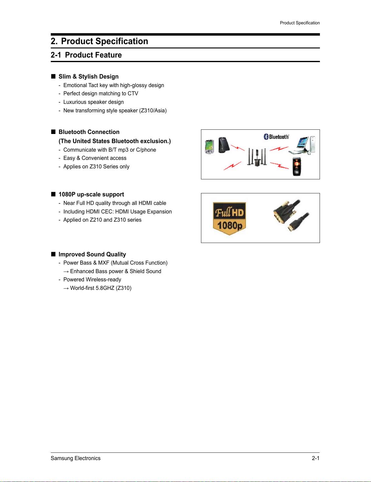
Bluetooth Connection
(The United States Bluetooth exclusion.)
- Communicate with B/T mp3 or C/phone
- Easy & Convenient access
- Applies on Z310 Series only
1080P up-scale support
- Near Full HD quality through all HDMI cable
- Including HDMI CEC: HDMI Usage Expansion
- Applied on Z210 and Z310 series
Improved Sound Quality
- Power Bass & MXF (Mutual Cross Function)
→ Enhanced Bass power & Shield Sound
- Powered Wireless-ready
→ World-first 5.8GHZ (Z310)
All manuals and user guides at all-guides.com
2-2 Samsung Electronics
Product Specification
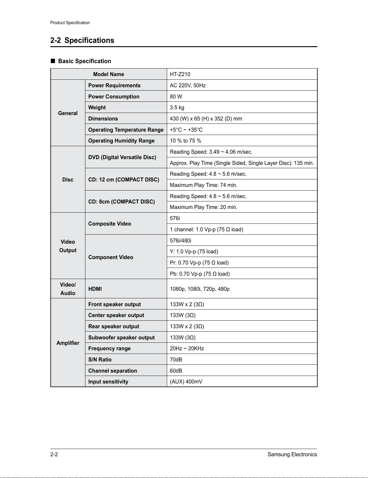
2-2 Specifications
Basic Specification
Model Name HT-Z210
General
Power Requirements
AC 220V, 50Hz
Power Consumption
80 W
Weight 3.5 kg
Dimensions 430 (W) x 65 (H) x 352 (D) mm
Operating Temperature Range
+5°C ~ +35°C
Operating Humidity Range
10 % to 75 %
Disc
DVD (Digital Versatile Disc)
Reading Speed: 3.49 ~ 4.06 m/sec.
Approx. Play Time (Single Sided, Single Layer Disc): 135 min.
CD: 12 cm (COMPACT DISC)
Reading Speed: 4.8 ~ 5.6 m/sec.
Maximum Play Time: 74 min.
CD: 8cm (COMPACT DISC)
Reading Speed: 4.8 ~ 5.6 m/sec.
Maximum Play Time: 20 min.
Video
Output
Composite Video
576i
1 channel: 1.0 Vp-p (75 Ω load)
Component Video
576i/480i
Y: 1.0 Vp-p (75 load)
Pr: 0.70 Vp-p (75 Ω load)
Pb: 0.70 Vp-p (75 Ω load)
Video/
Audio
HDMI 1080p, 1080i, 720p, 480p
Amplifier
Front speaker output
133W x 2 (3Ω)
Center speaker output
133W (3Ω)
Rear speaker output
133W x 2 (3Ω)
Subwoofer speaker output
133W (3Ω)
Frequency range
20Hz ~ 20KHz
S/N Ratio
70dB
Channel separation
60dB
Input sensitivity
(AUX) 400mV
All manuals and user guides at all-guides.com
Samsung Electronics 2-3
Product Specification
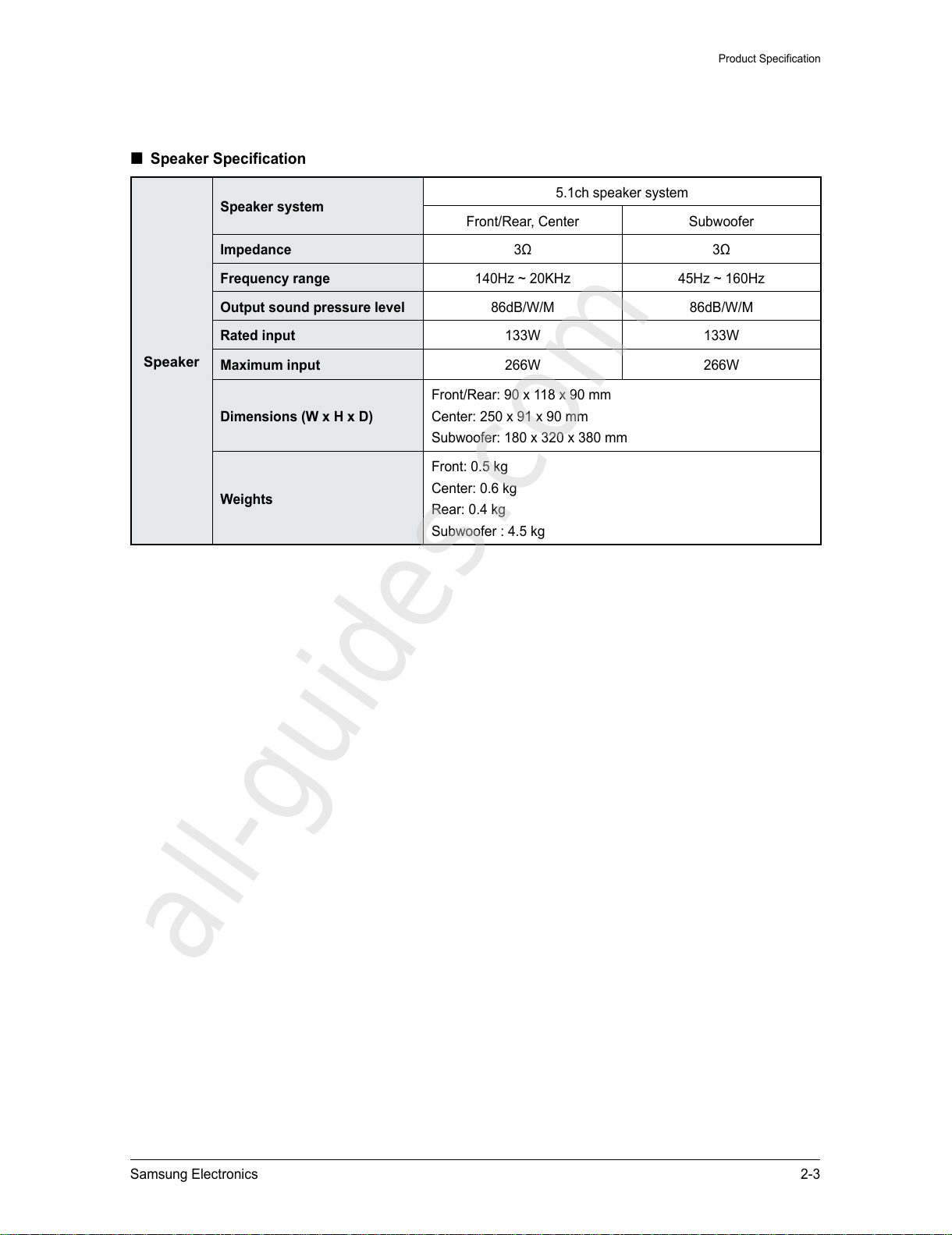
Speaker Specification
Speaker
Speaker system
5.1ch speaker system
Front/Rear, Center Subwoofer
Impedance 3Ω 3Ω
Frequency range
140Hz ~ 20KHz 45Hz ~ 160Hz
Output sound pressure level
86dB/W/M 86dB/W/M
Rated input
133W 133W
Maximum input
266W 266W
Dimensions (W x H x D)
Front/Rear: 90 x 118 x 90 mm
Center: 250 x 91 x 90 mm
Subwoofer: 180 x 320 x 380 mm
Weights
Front: 0.5 kg
Center: 0.6 kg
Rear: 0.4 kg
Subwoofer : 4.5 kg
All manuals and user guides at all-guides.com
all-guides.com
2-4 Samsung Electronics
Product Specification
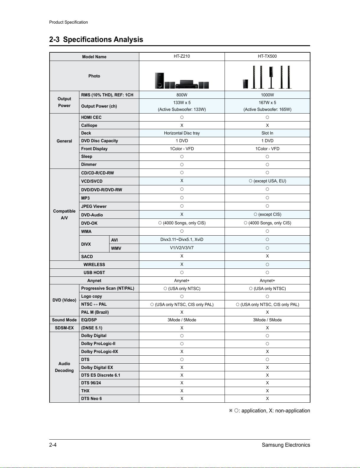
2-3 Specifications Analysis
Model Name
HT-Z210 HT-TX500
Photo
Output
Power
RMS (10% THD), REF: 1CH
800W 1000W
Output Power (ch)
133W x 5
(Active Subwoofer: 133W)
167W x 5
(Active Subwoofer: 165W)
General
HDMI CEC
Calliope X X
Deck Horizontal Disc tray Slot In
DVD Disc Capacity
1 DVD 1 DVD
Front Display
1Color - VFD 1Color - VFD
Sleep
Dimmer
Compatible
A/V
CD/CD-R/CD-RW
VCD/SVCD
X
(except USA, EU)
DVD/DVD-R/DVD-RW
MP3
JPEG Viewer
DVD-Audio
X
(except CIS)
DVD-OK
(4000 Songs, only CIS) (4000 Songs, only CIS)
WMA
DIVX
AVI
Divx3.11~Divx5.1, XviD
WMV
V1/V2/V3/V7
SACD
X X
WIRELESS
X
USB HOST
Anynet Anynet+ Anynet+
DVD (Video)
Progressive Scan (NT/PAL)
(USA only NTSC) (USA only NTSC)
Logo copy
NTSC ↔ PAL
(USA only NTSC, CIS only PAL) (USA only NTSC, CIS only PAL)
PAL M (Brazil)
X X
Sound Mode
EQ/DSP 3Mode / 5Mode 3Mode / 5Mode
SDSM-EX (DNSE 5.1) X X
Audio
Decoding
Dolby Digital
Dolby ProLogic-II
Dolby ProLogic-IIX
X X
DTS
Dolby Digital EX
X X
DTS ES Discrete 6.1
X X
DTS 96/24
X X
THX X X
DTS Neo 6
X X
: application, X: non-application
All manuals and user guides at all-guides.com
Samsung Electronics 2-5
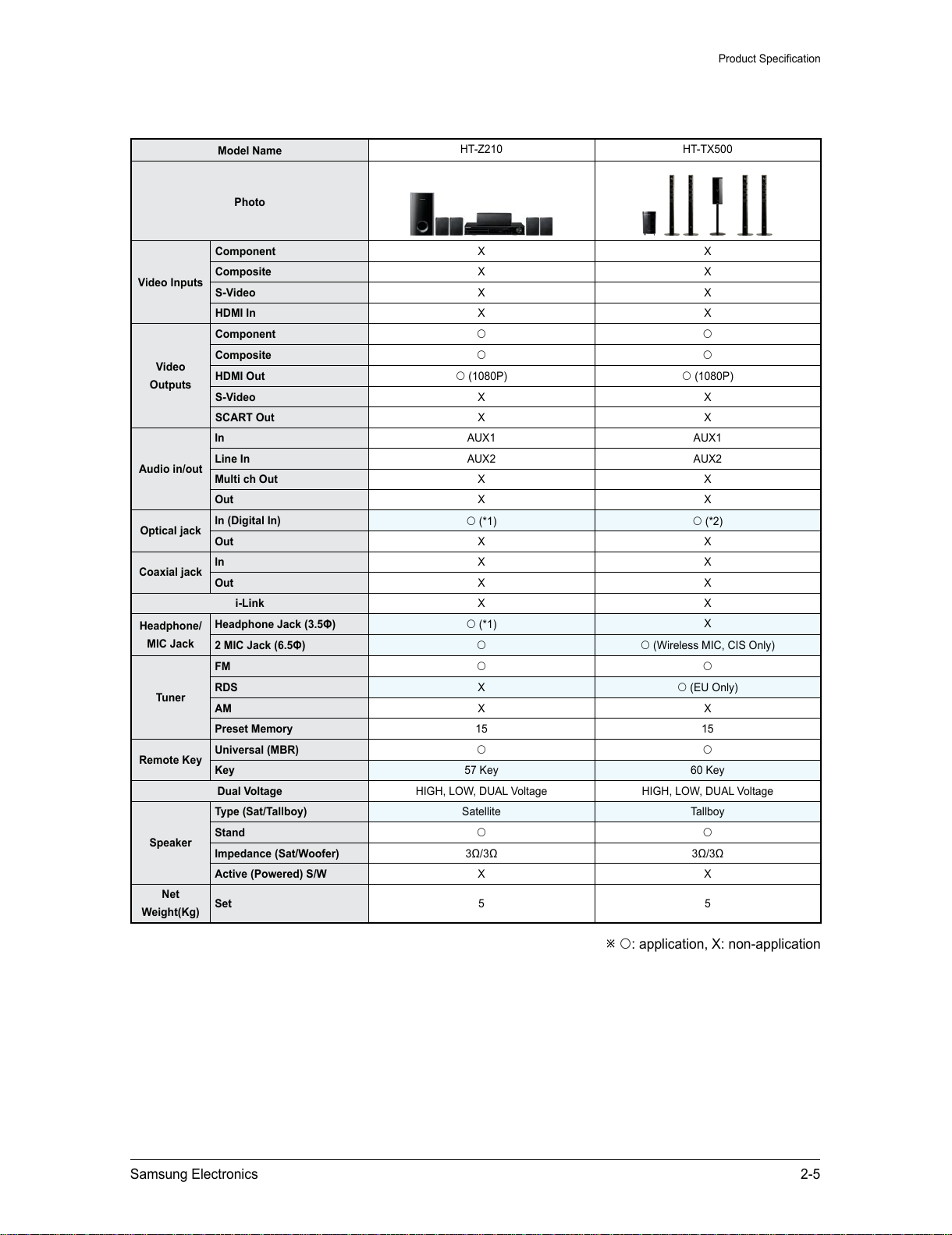
Product Specification
Model Name
HT-Z210 HT-TX500
Photo
Video Inputs
Component X X
Composite X X
S-Video X X
HDMI In
X X
Video
Outputs
Component
Composite
HDMI Out
(1080P) (1080P)
S-Video X X
SCART Out
X X
Audio in/out
In
AUX1 AUX1
Line In
AUX2 AUX2
Multi ch Out
X X
Out X X
Optical jack
In (Digital In)
(*1) (*2)
Out X X
Coaxial jack
In X X
Out X X
i-Link X X
Headphone/
MIC Jack
Headphone Jack (3.5Φ)
(*1)
X
2 MIC Jack (6.5Φ)
(Wireless MIC, CIS Only)
Tuner
FM
RDS
X
(EU Only)
AM
X X
Preset Memory
15 15
Remote Key
Universal (MBR)
Key 57 Key 60 Key
Dual Voltage
HIGH, LOW, DUAL Voltage HIGH, LOW, DUAL Voltage
Speaker
Type (Sat/Tallboy)
Satellite Tallboy
Stand
Impedance (Sat/Woofer)
3Ω/3Ω 3Ω/3Ω
Active (Powered) S/W
X X
Net
Weight(Kg)
Set 5 5
: application, X: non-application
All manuals and user guides at all-guides.com
2-6 Samsung Electronics
Product Specification
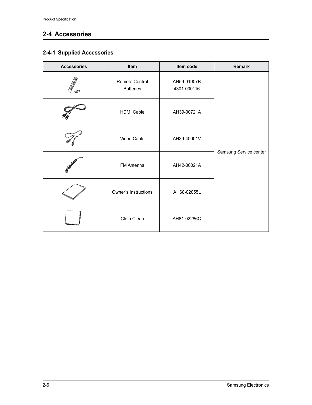
2-4 Accessories
2-4-1 Supplied Accessories
Accessories Item Item code Remark
Remote Control
Batteries
AH59-01907B
4301-000116
Samsung Service center
HDMI Cable AH39-00721A
Video Cable AH39-40001V
FM Antenna AH42-00021A
Owner’s Instructions AH68-02055L
Cloth Clean AH81-02286C
All manuals and user guides at all-guides.com
Samsung Electronics 3-1
Disassembly & Reassembly
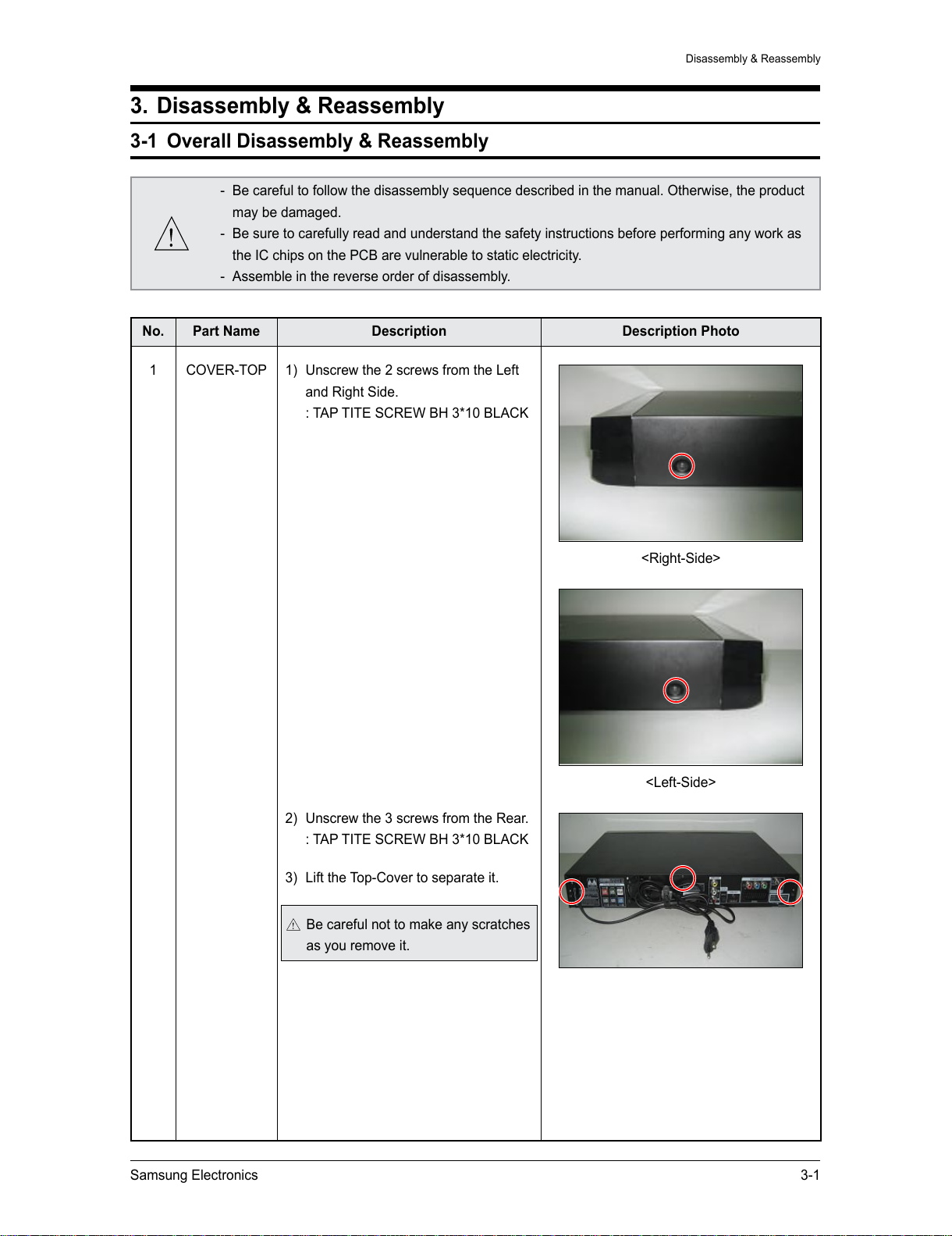
3. Disassembly & Reassembly
3-1 Overall Disassembly & Reassembly
- Be careful to follow the disassembly sequence described in the manual. Otherwise, the product
may be damaged.
- Be sure to carefully read and understand the safety instructions before performing any work as
the IC chips on the PCB are vulnerable to static electricity.
- Assemble in the reverse order of disassembly.
No. Part Name Description Description Photo
1 COVER-TOP 1) Unscrew the 2 screws from the Left
and Right Side.
: TAP TITE SCREW BH 3*10 BLACK
2) Unscrew the 3 screws from the Rear.
: TAP TITE SCREW BH 3*10 BLACK
3) Lift the Top-Cover to separate it.
Be careful not to make any scratches
as you remove it.
<Right-Side>
<Left-Side>
All manuals and user guides at all-guides.com
3-2 Samsung Electronics
Disassembly & Reassembly
No. Part Name Description Description Photo
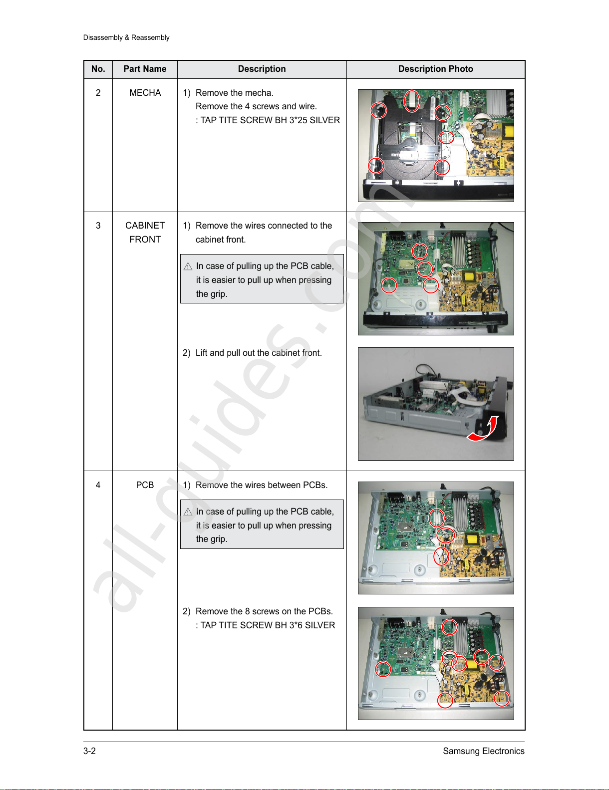
2 MECHA 1) Remove the mecha.
Remove the 4 screws and wire.
: TAP TITE SCREW BH 3*25 SILVER
3
CABINET
FRONT
1) Remove the wires connected to the
cabinet front.
In case of pulling up the PCB cable,
it is easier to pull up when pressing
the grip.
2) Lift and pull out the cabinet front.
4 PCB 1) Remove the wires between PCBs.
In case of pulling up the PCB cable,
it is easier to pull up when pressing
the grip.
2) Remove the 8 screws on the PCBs.
: TAP TITE SCREW BH 3*6 SILVER
All manuals and user guides at all-guides.com
all-guides.com
Samsung Electronics 3-3
Disassembly & Reassembly
No. Part Name Description Description Photo
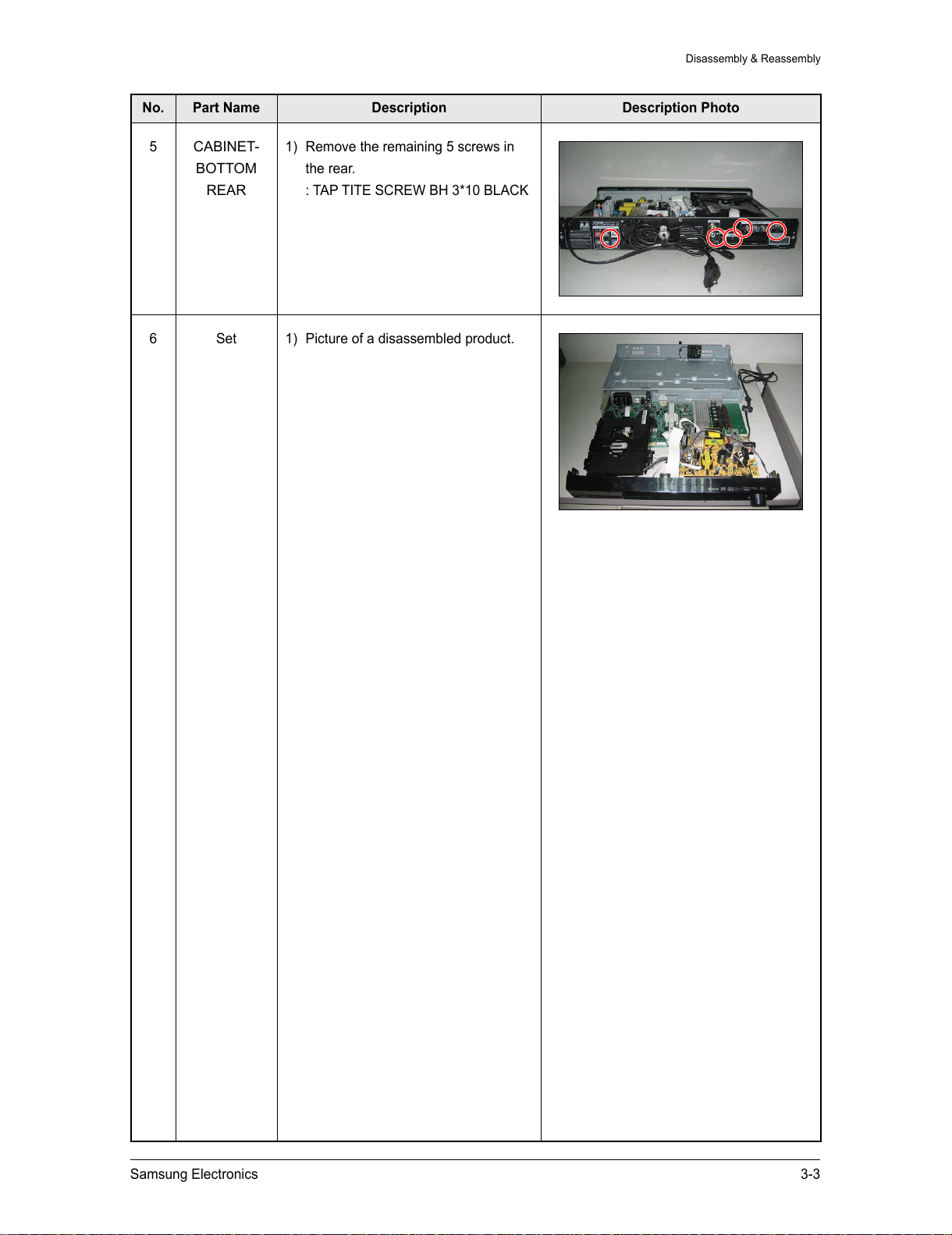
5
CABINET-
BOTTOM
REAR
1) Remove the remaining 5 screws in
the rear.
: TAP TITE SCREW BH 3*10 BLACK
6 Set 1) Picture of a disassembled product.
All manuals and user guides at all-guides.com

3-4 Samsung Electronics
MEMO
All manuals and user guides at all-guides.com
Samsung Electronics 4-1
Troubleshooting
4. Troubleshooting
4-1 Checkpoints by Error Mode ................................................................4-2
4-2 Measures to be taken when the Protection Circuit operates ...........
4-25
4-3 Initialization & Upgrade Methods ........................................................
4-27
All manuals and user guides at all-guides.com

4-2 Samsung Electronics
Troubleshooting
4-1 Checkpoints by Error Mode
4-1-1 Power Failure
UIC1 Main PCB;
pin 14, 40, 55, 89 5V?
Yes
Yes
Check for
POWER-SENSE (5V) at Main PCB
: pin 22 of UIC1, 5V?
POWER PCB (SMPS)
C73 (+) CHECK → 5V?
Check NORMAL
VOLTAGE at SMPS PCB
: D51
Replace CON3 wire
Check pattern from MCON2
to pin 22 of UIC1
Check for circuit at SMPS
PCB; ICM01, Fuse (F1), D81,
T1, T2
Replace D51.
Check Resistance from GND
to pin 22 of MICOM (UIC1).
If short (0 ohm), Replace
MICOM (UIC1)
No
No
Yes
No
Yes
No
The power does not turn on.
When POWER ON
for Front PCB, Check for
HIGH voltage (5V) at
UIC2; pin 13, 43
Replace the VFD DRIVER IC
(ZIC1).
No
Yes
A
All manuals and user guides at all-guides.com
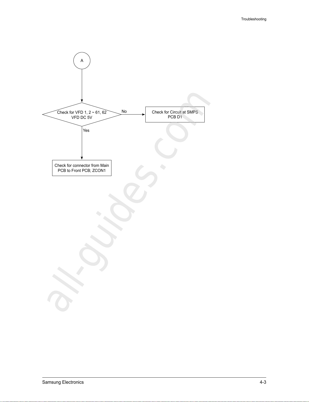
Samsung Electronics 4-3
Troubleshooting
Check for connector from Main
PCB to Front PCB; ZCON1
Yes
Check for Circuit at SMPS
PCB D1
No
Check for VFD 1, 2 ~ 61, 62
VFD DC 5V
A
All manuals and user guides at all-guides.com
all-guides.com
4-4 Samsung Electronics
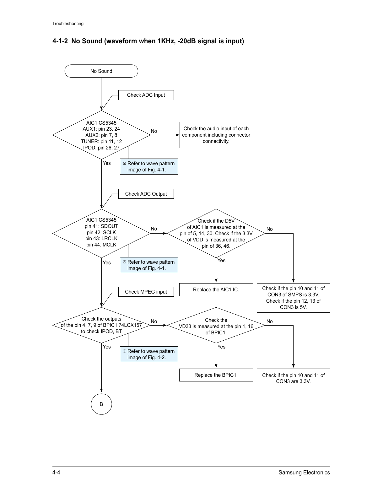
Troubleshooting
4-1-2 No Sound (waveform when 1KHz, -20dB signal is input)
Refer to wave pattern
image of Fig. 4-1.
Refer to wave pattern
image of Fig. 4-2.
AIC1 CS5345
AUX1: pin 23, 24
AUX2: pin 7, 8
TUNER: pin 11, 12
IPOD: pin 26, 27
Yes
AIC1 CS5345
pin 41: SDOUT
pin 42: SCLK
pin 43: LRCLK
pin 44: MCLK
Check if the D5V
of AIC1 is measured at the
pin of 5, 14, 30. Check if the 3.3V
of VDD is measured at the
pin of 36, 46.
Replace the AIC1 IC.
Check the audio input of each
component including connector
connectivity.
Check if the pin 10 and 11 of
CON3 of SMPS is 3.3V.
Check if the pin 12, 13 of
CON3 is 5V.
No
No
No
No Sound
Yes
Yes
B
Check the outputs
of the pin 4, 7, 9 of BPIC1 74LCX157
to check IPOD, BT
Check the
VD33 is measured at the pin 1, 16
of BPIC1.
Replace the BPIC1.
Check if the pin 10 and 11 of
CON3 are 3.3V.
No
No
Yes
Yes
Check ADC Input
Check ADC Output
Check MPEG input
Refer to wave pattern
image of Fig. 4-1.
All manuals and user guides at all-guides.com
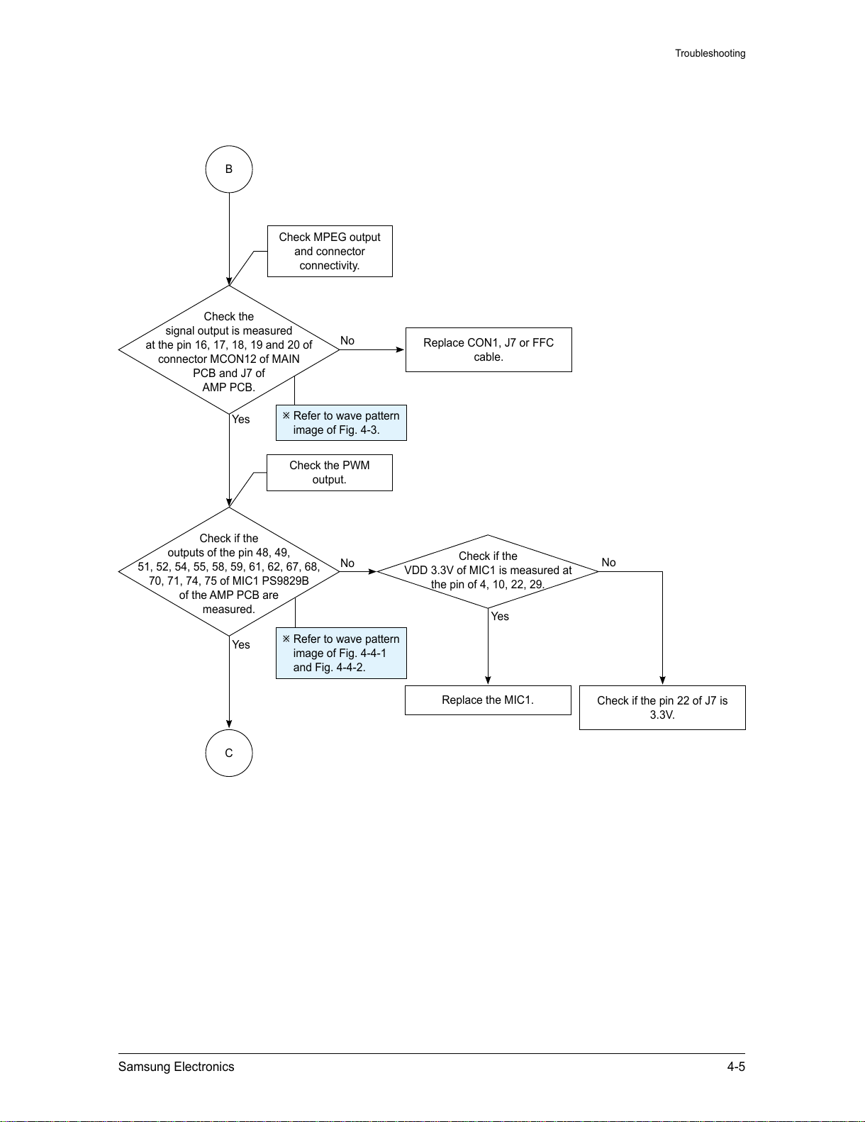
Samsung Electronics 4-5
Troubleshooting
Yes
Replace CON1, J7 or FFC
cable.
No
Check the
signal output is measured
at the pin 16, 17, 18, 19 and 20 of
connector MCON12 of MAIN
PCB and J7 of
AMP PCB.
Check MPEG output
and connector
connectivity.
B
C
Yes
Refer to wave pattern
image of Fig. 4-4-1
and Fig. 4-4-2.
Check if the
outputs of the pin 48, 49,
51, 52, 54, 55, 58, 59, 61, 62, 67, 68,
70, 71, 74, 75 of MIC1 PS9829B
of the AMP PCB are
measured.
Check if the
VDD 3.3V of MIC1 is measured at
the pin of 4, 10, 22, 29.
Replace the MIC1.
Check if the pin 22 of J7 is
3.3V.
No
No
Yes
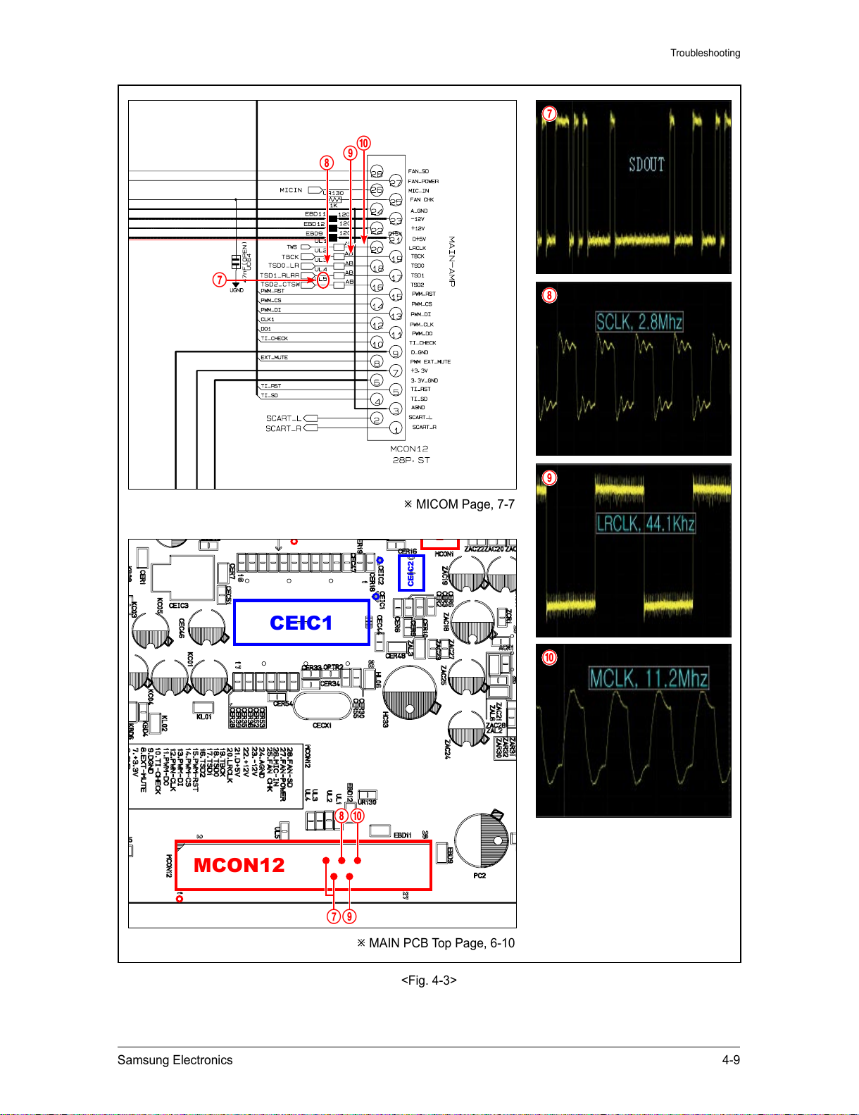
Check the PWM
output.
Refer to wave pattern
image of Fig. 4-3.
All manuals and user guides at all-guides.com
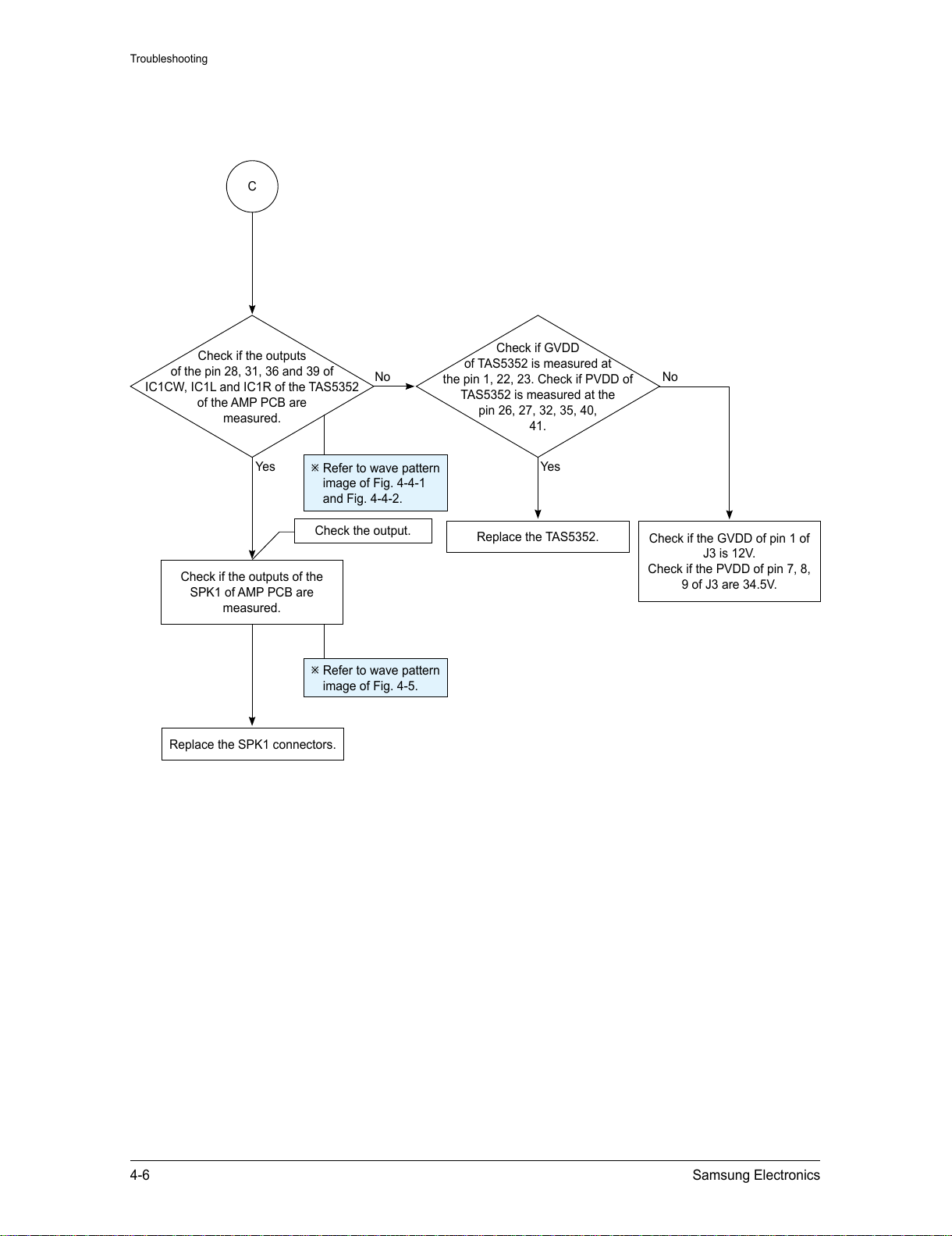
4-6 Samsung Electronics
Troubleshooting
C
Replace the SPK1 connectors.
Check the output.
Check if the outputs
of the pin 28, 31, 36 and 39 of
IC1CW, IC1L and IC1R of the TAS5352
of the AMP PCB are
measured.
Replace the TAS5352.
Check if the GVDD of pin 1 of
J3 is 12V.
Check if the PVDD of pin 7, 8,
9 of J3 are 34.5V.
No
Yes
Check if GVDD
of TAS5352 is measured at
the pin 1, 22, 23. Check if PVDD of
TAS5352 is measured at the
pin 26, 27, 32, 35, 40,
41.
Yes
No
Check if the outputs of the
SPK1 of AMP PCB are
measured.
Refer to wave pattern
image of Fig. 4-5.
Refer to wave pattern
image of Fig. 4-4-1
and Fig. 4-4-2.
All manuals and user guides at all-guides.com
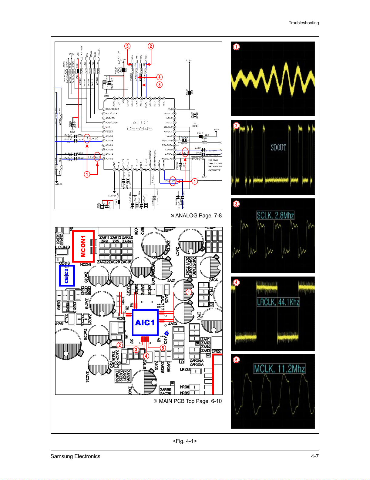
Samsung Electronics 4-7
Troubleshooting
ANALOG Page, 7-8
VIC1
IC31
AIC1
CEIC2
CN03
MCON1
JK7
VJ4
MAIN PCB Top Page, 6-10
<Fig. 4-1>
4
1
1
2
3
4
3
5 2
4
2
5
1
1
5
3
All manuals and user guides at all-guides.com
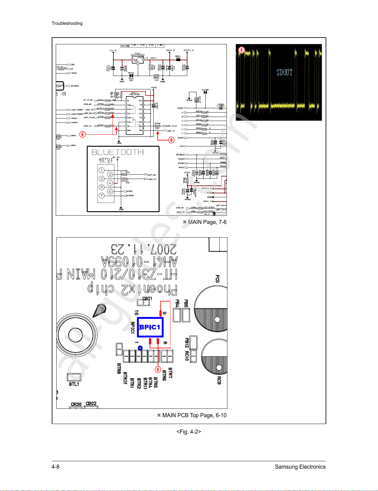
4-8 Samsung Electronics
Troubleshooting
MAIN Page, 7-6
RIC4
BPIC1
RIC3
MAIN PCB Top Page, 6-10
<Fig. 4-2>
6
6
6
6
All manuals and user guides at all-guides.com
all-guides.com
Samsung Electronics 4-9
Troubleshooting
MICOM Page, 7-7
VIC1
RIC3
IC31
AIC1
CEIC2
CEIC1
BIC5
MCON12
MCON15
CN03
CECJ1
MCON1
JK7
VJ4
MAIN PCB Top Page, 6-10
<Fig. 4-3>
7
7
7
8
9
9
0
0
8
0
9
8
All manuals and user guides at all-guides.com
 Loading...