

Instruction Manual
Digital Surround
AV Receiver System
HT-AS700
1
Safety Warnings
This symbol indicates that dangerous voltage which
can cause electric shock is present inside this unit.
This symbol alerts you to important operating and
maintenance instructions accompanying the unit.
WARNING: To reduce the risk of fire or electric shock, do not
expose this appliance to rain or moisture.
CAUTION: TO PREVENT ELECTRIC SHOCK, MATCH
WIDE BLADE OF PLUG TO WIDE SLOT, FULLY
INSERT.
Wiring the Main Power Supply Plug(UK Only)
IMPORTANT NOTICE
The main lead on this equipment is supplied with a moulded plug incorporating a fuse. The value of the fuse is indicated on the pin
face of the plug and if it requires replacing, a fuse approved to BS1362 of the same rating must be used.
Never use the plug with the fuse cover removed. If the cover is detachable and a replacement is required, it must be of the same
colour as the fuse fitted in the plug. Replacement covers are available from your dealer.
If the fitted plug is not suitable for the power points in your house or the cable is not long enough to reach a power point, you should
obtain a suitable safety approved extension lead or consult your dealer for assistance.
However, if there is no alternative to cutting off the plug, remove the fuse and then safely dispose of the plug. Do not connect the
plug to a main socket as there is a risk of shock hazard from the bared flexible cord.
Never attempt to insert bare wires directly into a main socket. A plug and fuse must be used at all times.
IMPORTANT
The wires in the main lead are coloured in accordance with the following code:–
BLUE = NEUTRAL BROWN = LIVE
As these colours may not correspond to the coloured markings identifying the terminals in your plug, proceed as
follows:–
The wire coloured BLUE must be connected to the terminal marked with the letter N or coloured BLUE or BLACK.
The wire coloured BROWN must be connected to the terminal marked with the letter L or coloured BROWN or RED.
WARNING: DO NOT CONNECT EITHER WIRE TO THE EARTH TERMINAL WHICH IS MARKED WITH
THE LETTER E OR BY THE EARTH SYMBOL , OR COLOURED GREEN OR GREEN
AND YELLOW.
RISK OF ELECTRIC SHOCK.
DO NOT OPEN
CAUTION:
TO REDUCE THE RISK OF ELECTRIC SHOCK, DO NOT
REMOVE REAR COVER. NO USER SERVICEABLE
PARTS INSIDE. REFER SERVICING TO QUALIFIED
SERVICE PERSONNEL.
CLASS 1 LASER PRODUCT
This Compact Disc player is classified
as a CLASS 1 LASER product.
CAUTION
2
Precautions
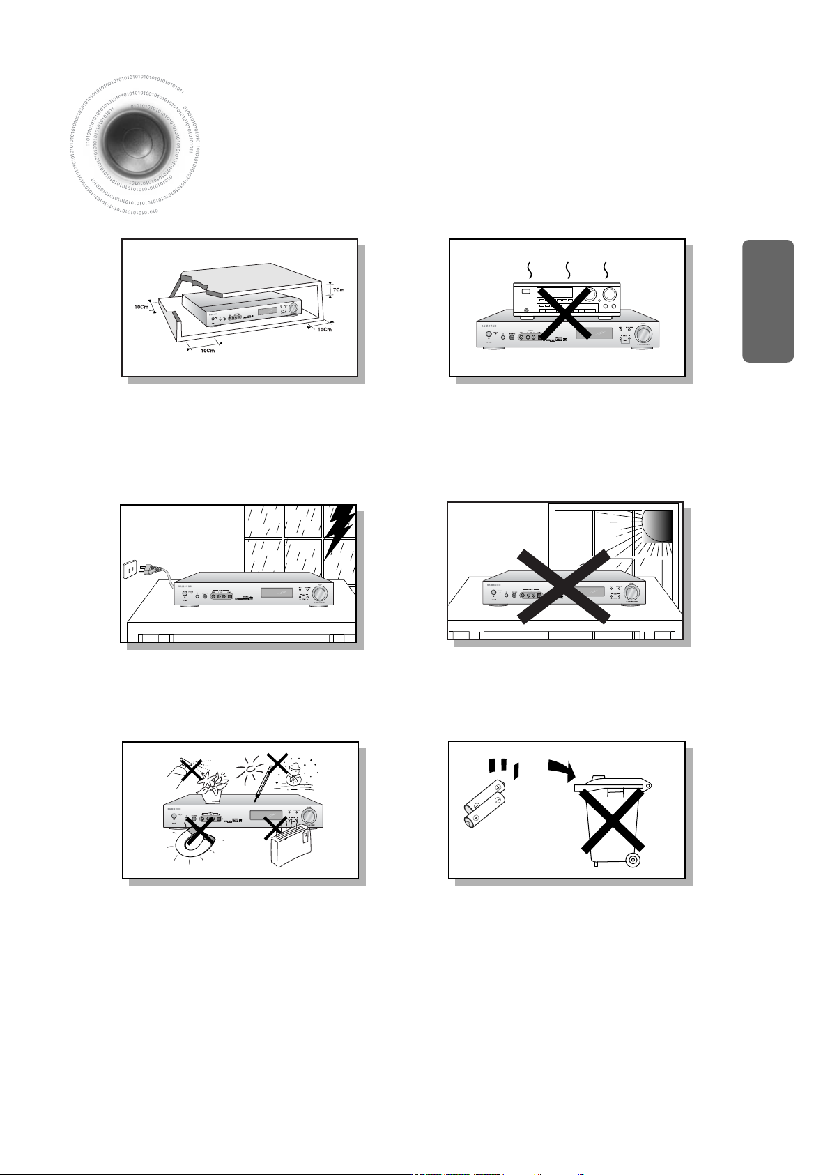
Ensure that the AC power supply in your house complies with the identification sticker located on the back of your player. Install
your player horizontally, on a suitable base (furniture), with enough space around it for ventilation (3~4inches). Make sure the
ventilation slots are not covered. Do not stack anything on top of the player. Do not place the player on amplifiers or other
equipment which may become hot. Before moving the player, ensure the disc tray is empty. This player is designed for
continuous use. Switching off the DVD player to the stand-by mode does not disconnect the electrical supply. In order to
disconnect the player completely from the power supply, remove the main plug from the wall outlet, especially when left unused
for a long period of time.
Protect the player from moisture(i.e. vases) , and excess
heat(e.g.fireplace) or equipment creating strong magnetic or
electric fields (i.e.speakers...). Disconnect the power cable from
the AC supply if the player malfunctions. Your player is not
intended for industrial use.
Use of this product is for personal use only.
Condensation may occur if your player or disc have been
stored in cold temperatures.
If transporting the player during the winter, wait approximately 2
hours until the unit has reached room temperature before using.
During thunderstorms, disconnect AC main plug from
the wall outlet.
Voltage peaks due to lightning could damage the unit.
Do not expose the unit to direct sunlight or other heat
sources.
This could lead to overheating and malfunction of the
unit.
The battery used with this product contain chemicals
that are harmful to the environment.
Do not dispose of batteries in the general household
trash.
PREP ARATION
√√
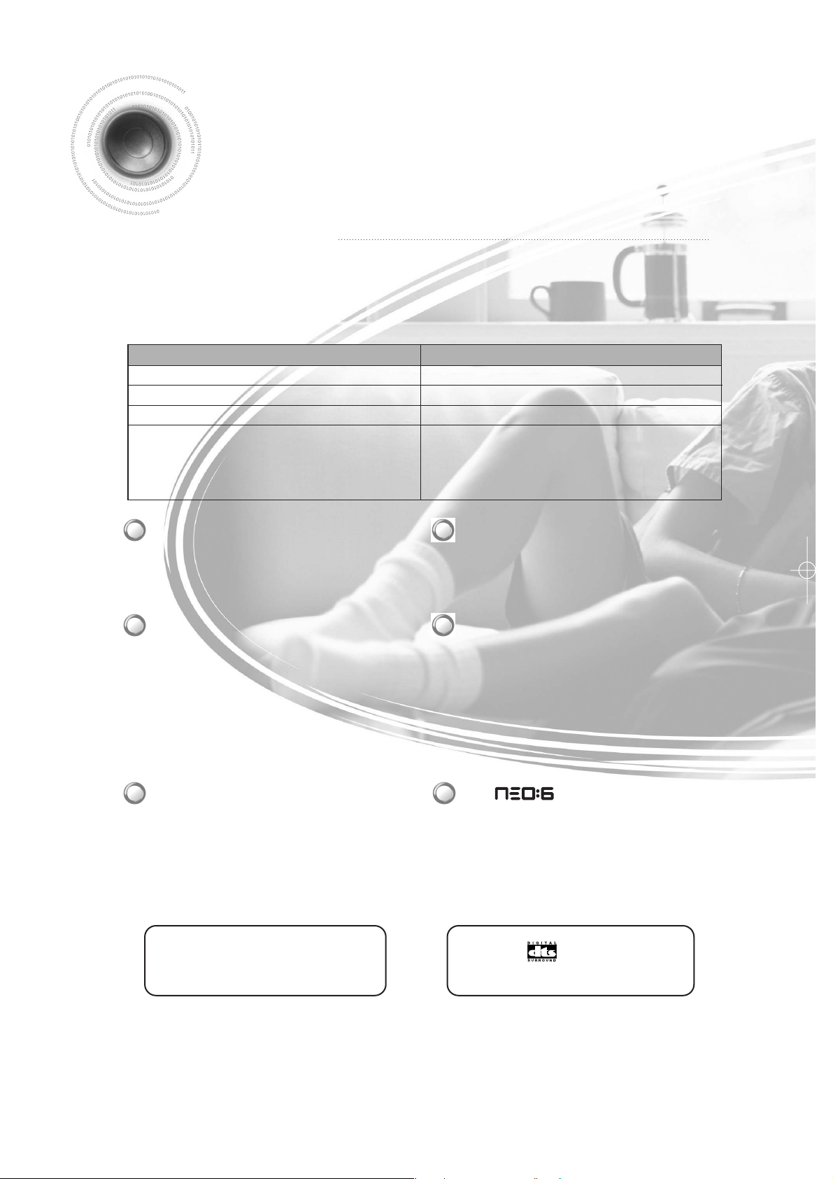
Let's find out difference between general amplifier and AV receiver!
General Amplifier
2 channels (left speaker and right speaker)
Play back music mainly
No decoder
Not play back various kinds of sound formats
AV Receiver
Multiple Channel (5.1 channel by default)
Play back music and video sound realistically
Has decoder
Dolby Pro Logic ll x
Dolby Pro Logic ll x is a new type of multiple
channel audio signal decoding method that
improves upon existing Dolby Pro Logic.
DTS (Digital Theater Systems)
DTS play backs 5.1 channel sound of wide-range
by playing sound of DVD and CD disk as surround
sound system.
DTS 96/24
DTS is the surround format implementing 5.1
channel multi channel sounds of 96KHz/24bit
without losing the image quality of DVD. In addition,
it can reproduce the matrix 6.1 of DTS 96/24
decoder signal.
DTS-ES
DTS-ES is the surround format implementing
surround type of discrete 6.1 channel while
preserving upper compatibility in response to
existing DTS Digital Sound format.
It is the latest digital sound format maximizing the
space quality and 360 surround experience by
adding rear center channels.
DOLBY DIGITAL EX
It not only significantly enhances space expression
capability of surround channel but also easily
implements the sound localization at the rear
according to sound field reproduction at 6.1 channel
including rear center channel.
DTS
It reproduces the digital PCM or analog stereo
sound source in 6.1 channels using the high
precision digital matrix of DTS only.
It refers to home theater exclusive amplifier by amplifying the audio signal from DVD and CD player as a core element of
home theater.
√√
What is AV receiver?
Features
3
Play back various kinds of sound formats including Dolby
Digital and DTS
Many input/output connectors
No noise using digital signal type
This product is manufactured with technical cooperation with Digital
Theater Systems, Inc., is the registered trademark of Digital
Theater Systems.
(c)1996 Digital Theater Systems, Inc. All rights Reserved.
Manufactured under license from Dolby Laboratories.
“Dolby”, “ProLogic” and double-D symbol are the trademark of Dolby Laboratories.
Confidential unpublished works
(c)1992-1997 Dolby Laboratories. All rights are Reserved.
Contents
4
PREPARATION
Safety Warnings ..............................................................................................................1
Precautions......................................................................................................................2
Features ..........................................................................................................................3
Contents ..........................................................................................................................4
Description ......................................................................................................................5
CONNECTIONS
Connecting the Speakers ...............................................................................................9
Connecting External Components ..................................................................................11
Connecting External Component.....................................................................................13
Connecting the FM Antenna............................................................................................14
OPERATION
Before Using AV Receivera .............................................................................................15
Selecting External Component Input ...............................................................................16
Setting the Speakera .......................................................................................................17
Setting DRC (Dynamic Range Compression) .................................................................21
Test Tone ........................................................................................................................22
Setting Speaker Level .....................................................................................................25
Dolby Pro Logic ll x Mode................................................................................................27
Dolby Pro Logic ll x Effect................................................................................................29
NEO:6 Mode....................................................................................................................31
SFE Mode........................................................................................................................33
EX/ES Mode ....................................................................................................................35
Stereo Mode ....................................................................................................................37
RADIO OPERATION
Listening to Radio ...........................................................................................................39
Presetting Radio Stations ...............................................................................................40
About RDS Broadcating ..................................................................................................41
MISCELLANEOUS
Convenient Functions .....................................................................................................43
Operating TV with Remote Control..................................................................................45
Operating VCR (DVD) with Remote Control....................................................................47
Before Calling for Service................................................................................................49
Specifications ..................................................................................................................51
PREP ARATION
Description
[
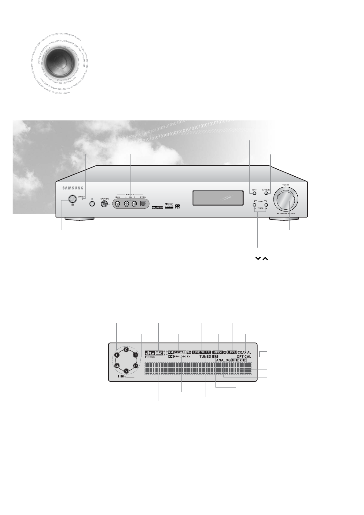
Front Panel
]
[
Display
]
POWER button EXTERNAL VIDEO
INPUT CONNECTOR
VOLUME CONTROL
REMOTE CONTROL Sensor EXTERNAL OPTICAL DIGITAL
AUDIO INPUT CONNECTOR
SELECTION button
TUNING ( ) button
POWER STANDBY Indicator
EXTERNAL AUDIO INPUT CONNECTOR
SURROUND button
HEADPHONE Jack INPUT button
5
S.W
SPEAKER INDICATOR
SUBWOOFER
LEVEL INDICATOR
DOLBY PRO LOGIC
IIX
INDICATOR
VARIOUS
FUNCTION
INDICATOR
RADIO BROADCASTING
RECEIVING INDICATOR
RADIO STEREO INDICATOR
ANALOG INDICATOR
RADIO FREQUENCY
INDICATOR
OPTICAL DIGITAL
INDICATOR
DTS ES 96/24
INDICATOR
LIVE SURROUND
INDICATOR
L.PCM INDICATOR
NEO:6
INDICATOR
DOLBY DIGITAL EX
INDICATOR
MPEG2
INDICATOR
COAXIAL DIGITAL INDICATOR
,
6
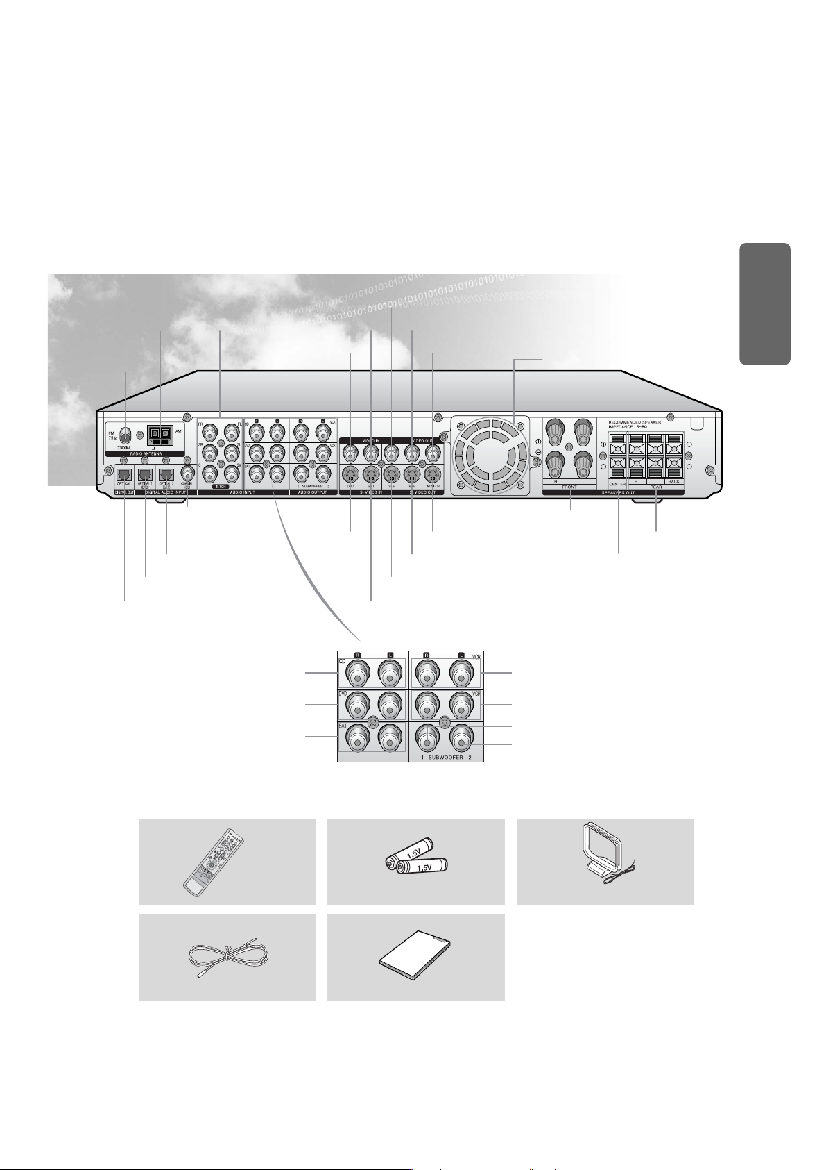
DVD VIDEO INPUT
CONNECTOR
COOLING PAN
SAT VIDEO INPUT
CONNECTOR
5.1 CH ANALOG
AUDIO CONNECTOR
VCR VIDEO INPUT CONNECTOR
AM ANTENNA
CONNECTOR
VCR VIDEO OUTPUT CONNECTOR
MONITOR VIDEO OUTPUT
CONNECTOR
FM ANTENNA
CONNECTOR
OPTICAL DIGITAL AUDIO OUTPUT
CONNECTOR
DVD OPTICAL DIGITAL AUDIO INPUT CONNECTOR
SAT OPTICAL DIGITAL AUDIO
INPUT CONNECTOR
CD COAXIAL DIGITAL
AUDIO INPUT
CONNECTOR
SAT S-VIDEO INPUT CONNECTOR
VCR S-VIDEO INPUT CONNECTOR
VCR S-VIDEO OUTPUT CONNECTOR
CENTER SPEAKER TERMINAL
FRONT SPEAKER TERMINAL
REAR SPEAKER TERMINAL
MONITOR S-VIDEO OUTPUT CONNECTOR
[
Rear Panel
]
Accessories
√√
œœ
CD AUDIO INPUT CONNECTOR
DVD AUDIO INPUT CONNECTOR
SAT AUDIO INPUT CONNECTOR
Remote Control
FM Antenna User’s Manual
Battery(AAA Size 1.5V) AM Antenna
VCR AUDIO INPUT CONNECTOR
VCR AUDIO OUTPUT CONNECTOR
SUBWOOFER OUTPUT CONNECTOR 1
SUBWOOFER OUTPUT CONNECTOR 2
DVD S-VIDEO
INPUT
CONNECTOR
PREP ARATION
USER’S GUIDE
Description
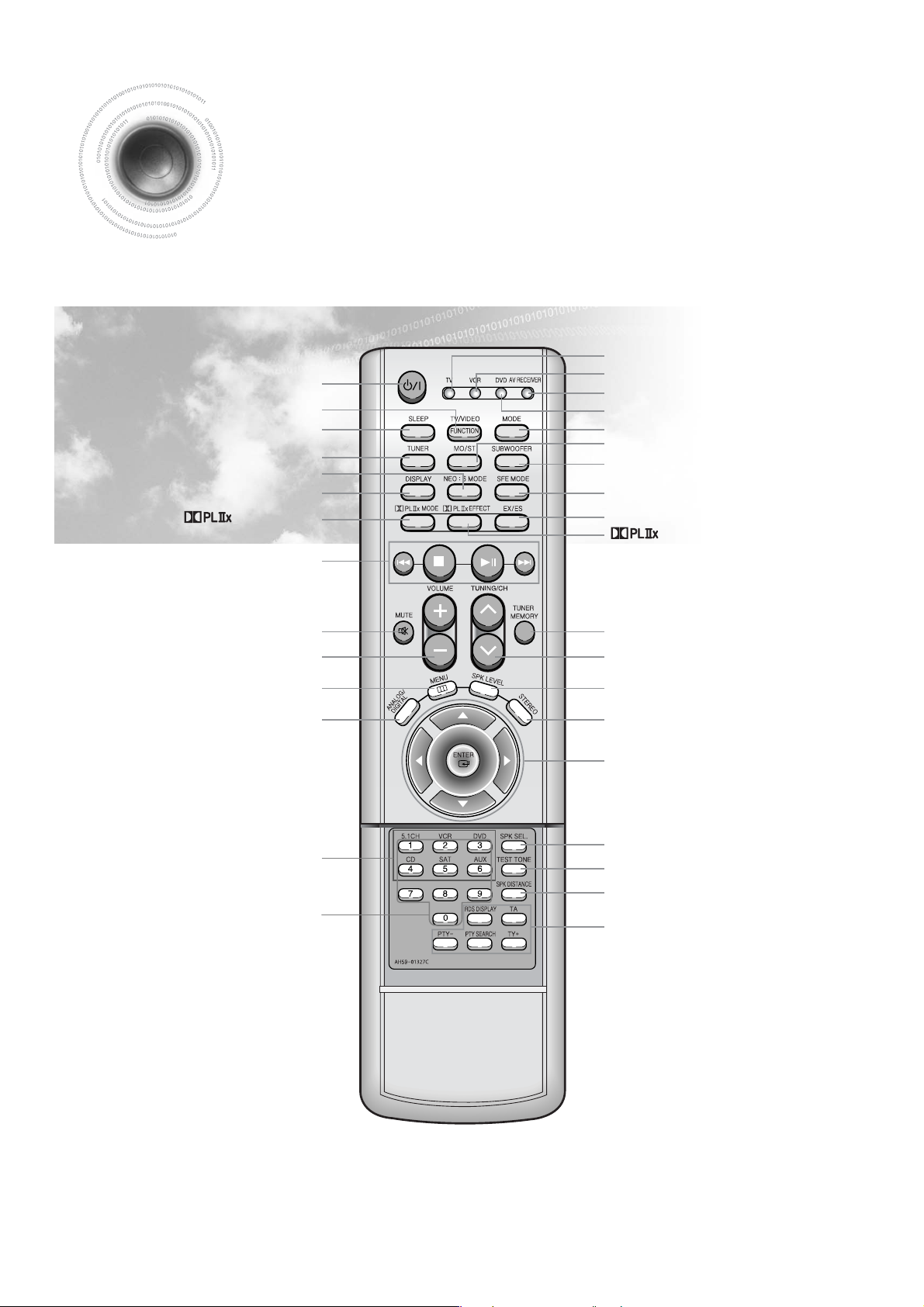
VOLUME CONTROL button
MUTE button
MENU button
ANALOG/DIGITAL button
POWER button
SLEEP button
TUNER button
NEO : 6 button
EXTERNAL DEVICE PLAYBACK button
DISPLAY button
MODE button
Direct Function Select button
TV Indicator
VCR Indicator
AV RECEIVER Indicator
TV/VIDEO
,
FUNCTION button
DVD Indicator
MODE button
MO/ST button
SUBWOOFER button
SFE MODE button
EX/ES button
EFFECT button
STEREO button
MOVE/SELECT button
TUNER MEMORY button
TUNING/CHANNEL button
SPEAKER LEVEL button
TEST TONE button
SPEAKER SETUP button
SPEAKER DISTANCE button
RDS Selection button
[
Remote Control
]
7
Number(0~9) buttons
8
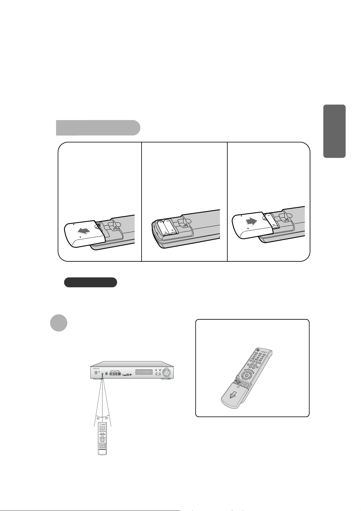
To open the remote control cover,
push the top of the cover, then slide
downward.
Insert Remote Batteries
The remote control can be used up to approximately 23
feet/7 meters in a straight line. It can also be operated at
a horizontal angle of up to 30° from the remote control
sensor.
Range of Operation of the Remote Control
Remove the battery
cover on the back of
the remote by
pressing down and
sliding the cover in
the direction of the
arrow.
1
Insert two 1.5V AAA
batteries, paying
attention to the correct
polarities (+ and –).
2
Replace the battery
cover.
3
Follow these precautions to avoid leaking or cracking batteries:
•
Place batteries in the remote control so they match the polarity:(+) to (+)and (–)to (–).
•
Use the correct type of batteries.Batteries that look similar may differ in voltage.
•
Always replace both batteries at the same time.
•
Do not expose batteries to heat or flame.
Caution !
PREP ARATION
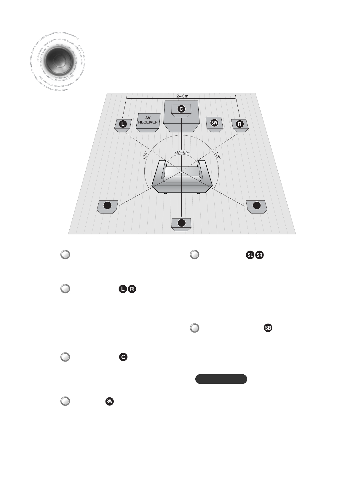
Connecting the Speakers
Before moving or installing the product, be sure to turn off the power and disconnect the power cord.
•
Place the rear left and right speaker at the interval of front
left and right speaker.
•
If there isn't enough now, place rear speakers to face
down other.
•
Place the rear speakers about 70 cm to 1 m above your
ear, facing slightly downwards.
❈ Unlike the front and center speakers, the rear speakers
and used to mainly sound effects and sound will not
come from them all the time.
Rear Speakers
•
If you place 1 rear center speaker, place it so that it faces
forward from the back of listener.
•
Place the rear center speaker about 70 cm to 1 m above
rear speakers, facing slightly downwards.
Rear Center Speaker
SL SR
SB
•
Adjust the angle of front left and right speakers so
that it can form 30 degree to the left and right from
the listening position.
•
Place the speakers so that their tweeters will be at
the same height as your ear.
•
Align the front face of the front speakers with the
front face of the center speaker or place them
slightly in front of the center speaker.
Front Speakers
•
It is best to install center speaker at the same height as
the front speakers.
•
You can also place center speaker directly over or
under the TV.
Center Speaker
•
Place AV Receiver on the dedicated stand or chest of
living room or under the TV stand properly.
Position of AV Receiver
•
The position of the subwoofer is not so critical. Place it
anywhere you like.
•
Usually, it is placed by a corner near the front speakers.
Subwoofer
When you place the speaker on the wall, make sure
to fasten it tightly so that it may not fall off.
9
Caution!
10
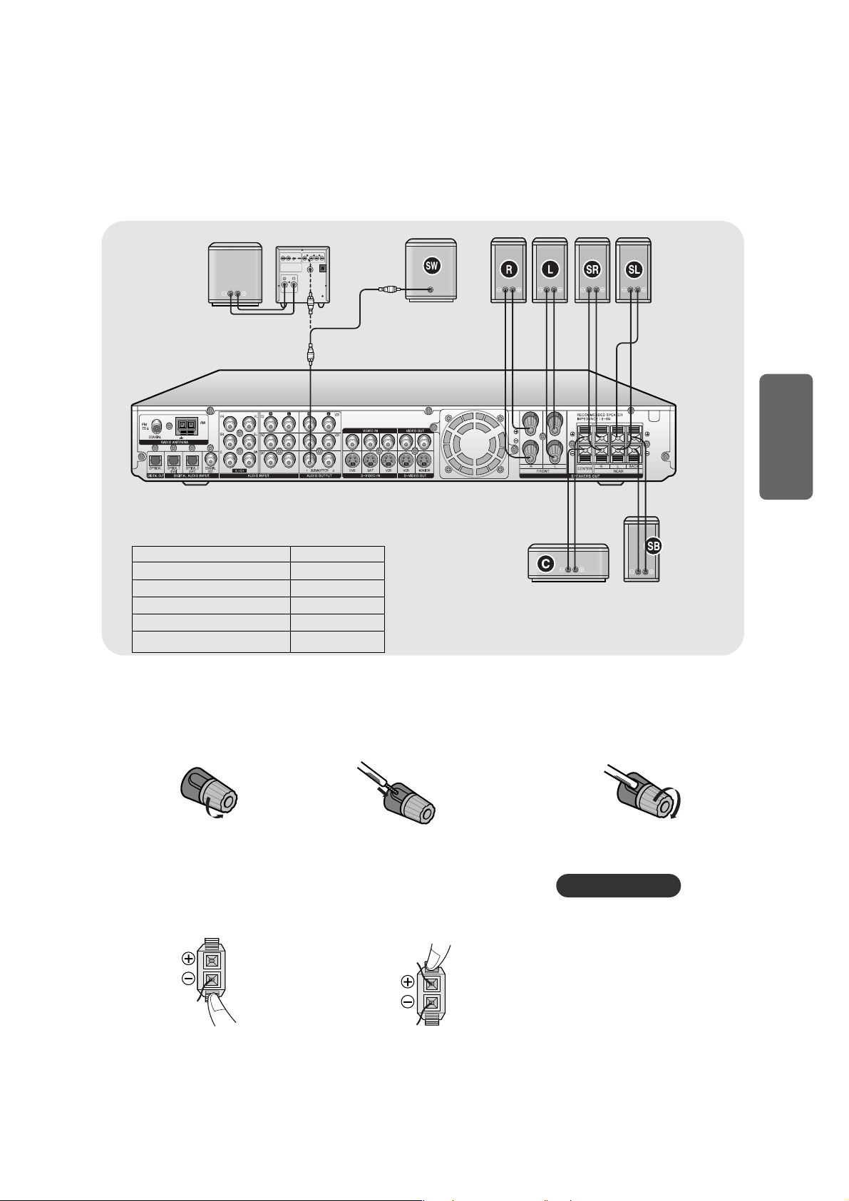
CONNECTIONS
•
Never touch speaker terminals while
the power is on. Doing so could
result in electric shock.
•
Make sure the polarities (+ and -)
are correctly.
1
√ Connecting Front Speaker Wire
MAIN UNIT AV-R700
FRONT SPEAKER PSAF700E
CENTER SPEAKER PSAC700E
REAR SPEAKER PSAR700E
REAR CENTER SPEAKER PSAB700E
ACTIVE SUB WOOFER PSAW700E
SYSTEM MODEL NAME : HT-AS700
√ Connecting Center/Rear Speaker Wire
PASSIVE
SUBWOOFER
ACTIVE SUBWOOFER
(BUILT-IN POWER
AMPLIFIER)
PSAW700E
POWER
AMPLIFIER
FRONT (R)
PSAF700E
FRONT (L)
PSAF700E
REAR (R)
PSAR700E
REAR (L)
PSAR700E
MAIN UNIT
AV-R700
CENTER
PSAC700E
REAR CENTER
PSAB700E
Caution!
Turn and loosen the
speaker connector.
2
1
Press the tab of the
speaker connector.
2
Insert the black wire into the black(-)
terminal and the red wire into the
red(+) terminal.
3
Turn and fasten the
speaker connector.
Insert the black wire into the black(-)
terminal and the red wire into the
red(+) terminal.
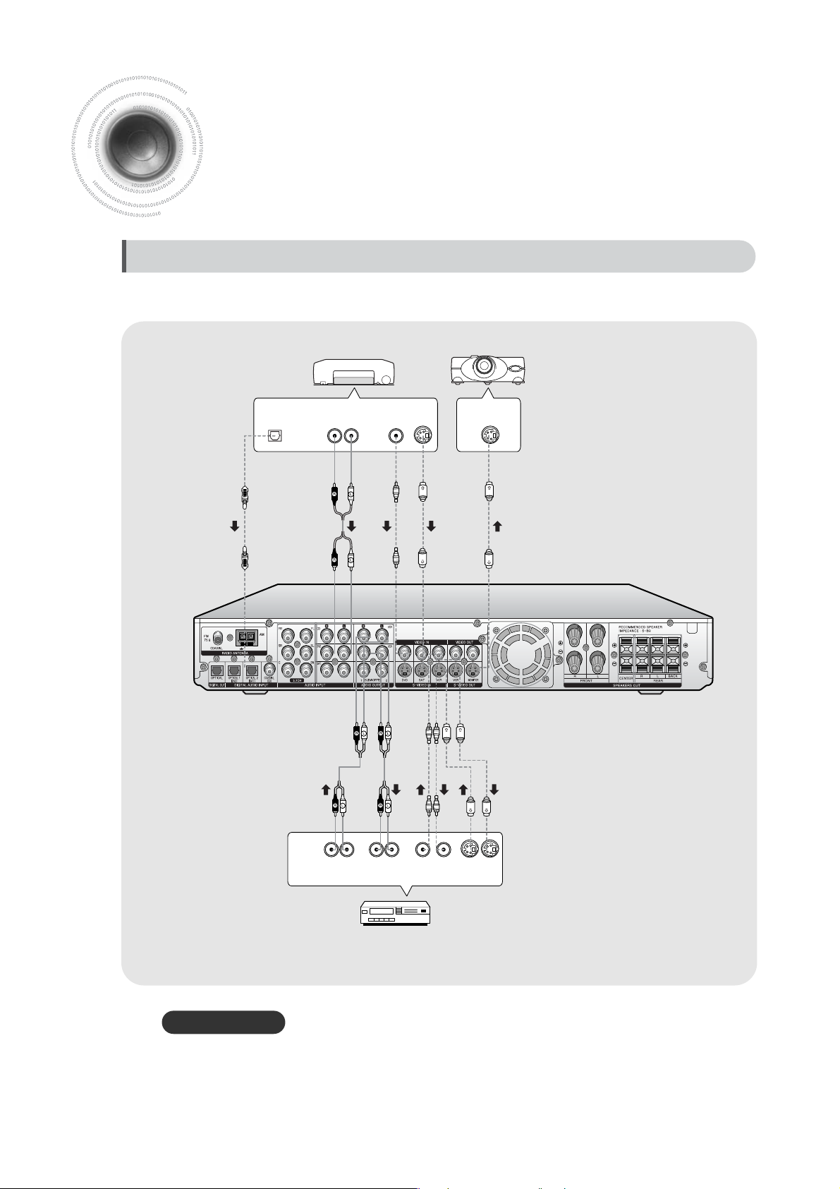
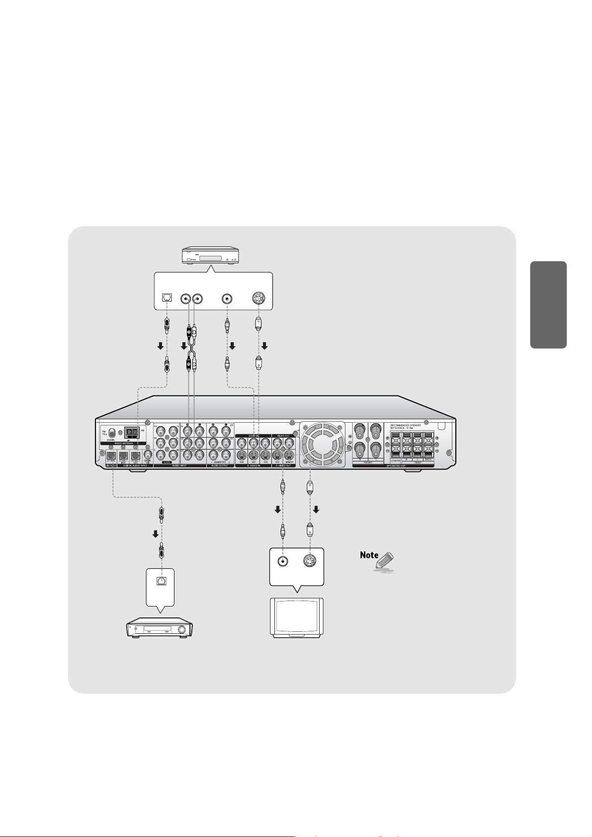
Connecting External Components
DVD Player
Video ProjectorVideo Player
•
Disconnect the power plug from the outlet if you do not use this unit for long period of time.
Before moving or installing the product, be sure to turn off the power and disconnect the power cord.
Connecting Video Component
11
Caution!
DIGITAL
OUT
AUDIO
OUT
VIDEO
S-VIDEO
OUT
OUT
LR
S-VIDEO
IN
LRLR
AUDIO
OUT
AUDIO
IN
VIDEO
OUT IN
S-VIDEO
OUT IN
VIDEOINS-VIDEO
IN
DIGITAL
OUT
AUDIO
OUT
VIDEO
OUT
S-VIDEO
OUT
LR
DIGITAL
IN
SA T Player
TV MD Player
•
If the Audio Output connector of external
component is only 1, connect Audio Output
connector or external component to either of
Audio Input connector (right or left) of main unit.
•
Connect the red cable of audio cable to red
connector and white cable to white connector.
•
When you connect Video Input connector of
external component to Video Output connector
of main unit, connect Video Input connector of
external component either to Video Output
connector or S-Video Output connector.
12
CONNECTIONS
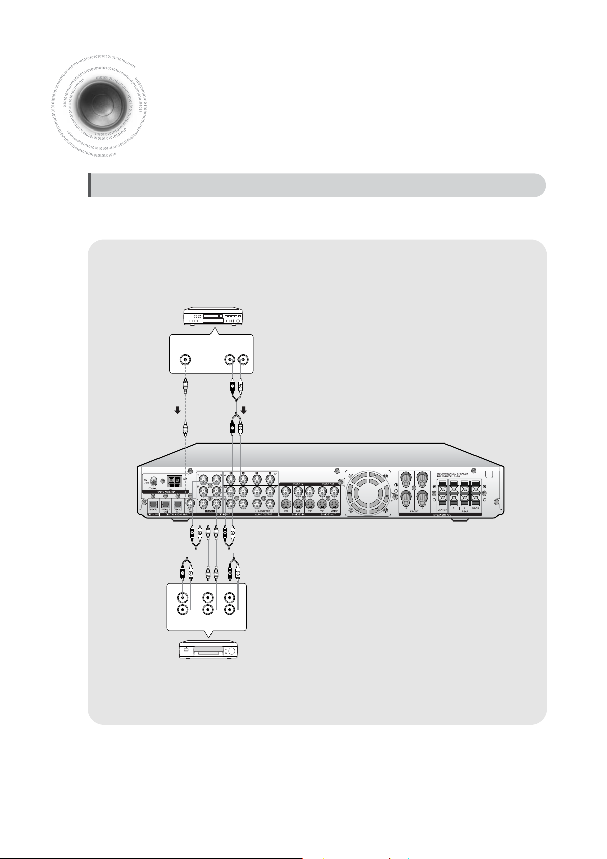
Connecting External Component
LR
DIGITAL
OUT
AUDIO
OUT
FRONT SURR.
SUB
WOOFER
L
R
L
R
CENTER
CD Player
DVD or 5.1 Channel Player
Before moving or installing the product, be sure to turn off the power and disconnect the power cord.
Connecting Audio Component/ 5.1 Channel
13
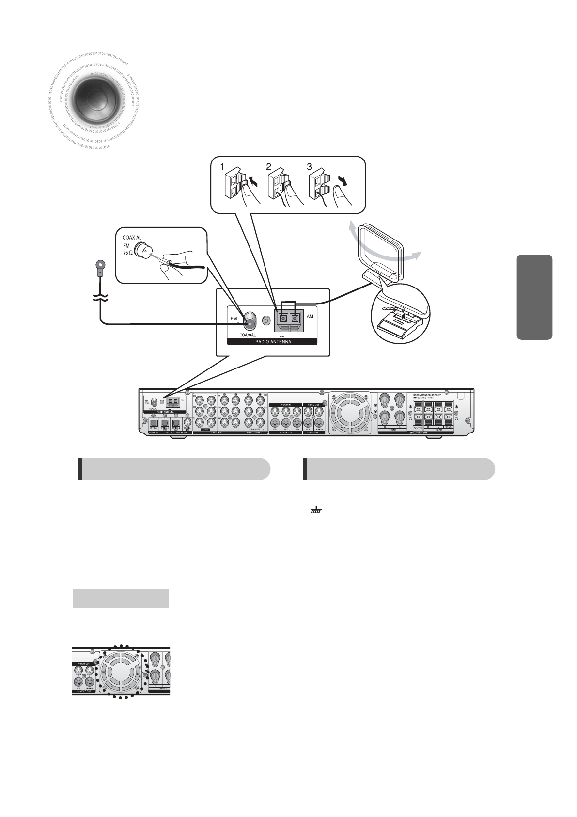
14
1. Connect the FM antenna supplied to the FM
75ΩCOAXIAL terminal as a temporary mea-sure.
2. Slowly move the antenna wire around until you find
a location where reception is good, then fasten it to
a wall or other rigid surface.
1. Connect the AM loop antenna supplied to the AM
and terminals.
2. If reception is poor, connect an outdoor single vinyl-
covered wire to the AM ter-minal. (Keep the AM loop
antenna con-nected).
The cooling fan dissipates the heat generated inside the unit so that the unit can
be operated normally. The cooling fan is activated automatically to supply cool air
to the unit.
Please observe the following cautions for your safety.
•
Make sure the unit is well-ventilated. If the unit has poor ventilation, the temperature inside the
unit could rise and may damage it.
•
Do not obstruct the cooling fan or ventilation holes. (If the cooling fan or ventilation holes are
covered with a newspaper or cloth, heat may build up inside the unit and fire may result.)
Connecting the FM and AM
Antennas
FM antenna connection
If AM reception is poor, connect an
outdoor AM antenna(not supplied).
FM Antenna (supplied)
AM Loop Antenna
(supplied)
Snap the tabs on the loop into the
slots of the base to assemble the
AM loop antenna.
COOLING F AN
AM antenna connection
CONNECTIONS
Before Using AV Receiver
Turning On/Off
Functions of Dedicated Remote Control
Connect the power plug to the outlet.
1
Press the POWER ( ) button of the main unit.
•
This unit will be turned on or off.
2
MAIN UNIT
REMOTE CONTROL
Press MODE button.
•
Each time you press this button, it will select and blink TV indicator ➝ VCR indicator
➝DVD indicator ➝AV Receiver indicator in turn.
•
You can operate TV after TV indicator blinking.
You can operate VCR after VCR indicator blinking.
You can operate DVD after DVD indicator blinking.
You can operate AV Receiver after AV Receiver indicator blinking.
•
This unit will not turned on or off even if you press the POWER ( ) button of
remote controller while main unit is turned off.
•
When you turn off the power by pressing the POWER ( ) button of remote
control, this unit will be standby mode.To completely turn off the power, press the
POWER ( ) button of the main unit. Standby indicator will be turned off.
•
Basic operation of remote control is set up based on Samsung products.
Refer to page 45~48 for more details on operation method.
You can operate TV, VCR, DVD, AV Receiver with one remote control.
15
To set the menu function of external component
Press the MENU button.
•
Menu setup screen of TV, VCR and DVD Player will appear.
REMOTE CONTROL
Press the POWER ( ) button of the remote control while main unit is turned on.
•
This unit will be turned on or off.
You can listen ti sound in Analog 2 Channels or Dolby Digital 5.1 Channel using this unit.
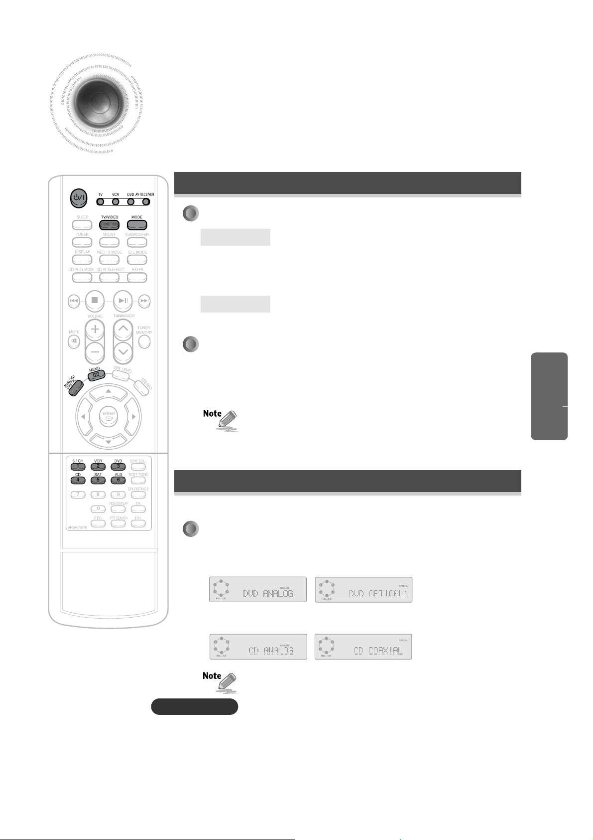
16
Press the FUNCTION button.
•
When you select the audio external component (external component without
Video Output connector), the image of video external component (external
component with Video Output connector) used last will appear in the TV screen.
•
You can watch the image of video external component while listening to sound of
audio external component.
Selecting External Component Input
•
You can enjoy Dolby Digital effect only if you connect Audio Output connector of
external audio component to optical/coaxial digital Audio Input connector of main unit.
To Select the Function
To Select Analog/Digital Input
REMOTE CONTROL
•
You can directly select 5.1CH, VCR, DVD, CD, SAT, or AUX.
•
For DVD, SAT, AUX Function
ANALOG and OPTICAL (1, 2, 3) will be selected repetitively.
•
For CD Function
ANALOG and COAXIAL will be selected repetitively.
MAIN UNIT
REMOTE CONTROL
Press INPUT button.
•
Each time you press the this button, 5.1CH MULTI CH ➝ CD ➝ DVD ➝SAT ➝VCR ➝AUX
➝FM ➝AM will be selected in turn.
Press the ANALOG/DIGIT AL button.
•
You can operate this function only with remote controller.
•
This function will be selected in analogue only for VCR function, and will not work for 5.1CH MULTI CH function.
Caution!
Method 1
Press DIRECT FUNCTION Select button.
Method 2
Press the FUNCTION button.
•
Each time you press the this button, 5.1CH MULTI CH ➝ CD ➝ DVD ➝SAT ➝VCR ➝
AUX ➝FM ➝AM will be selected in turn.
OPERA TION
 Loading...