

Page 1

Radio Access Network
5G NR HRU
Installation Manual
Describes product installation and requirement procedure.
Document Version 1.0
August 2018
Document Number: 2600-00MST9GAA
Page 2

© 2018 SAMSUNG Electronics Co., Ltd.
All Rights Reserved. The contents of this document/presentation contain proprietary information that
must be kept confidential. No part of this document shall be photocopied, reproduced, stored in a
retrieval system, or transmitted, in any form or by any means whether, electronic, mechanical, or
otherwise without the prior written permission of SAMSUNG Electronics Co., Ltd.
No warranty of accuracy is given concerning the contents of the information contained in this
publication. To the extent permitted by law no liability (including liability to any person by reason of
negligence) will be accepted by SAMSUNG Electronics Co., Ltd., its subsidiaries or employees for
any direct or indirect loss or damage caused by omissions from or inaccuracies in this document.
SAMSUNG Electronics Co., Ltd. reserves the right to change details in this publication without
notice.
SNMTC-v3-0312
This manual should be read and used as a guideline for properly installing and/or operating
the product. Owing to product variations across the range, any illustrations and photographs
used in this manual may not be a wholly accurate depiction of the actual products you are
using.
This manual may be changed for system improvement, standardization and other technical
reasons without prior notice.
Page 3

5G NR HRU Installation Manual v1.0 iii
Copyright © 2018, All Rights Reserved.
Samsung Networks documentation is available at http://www.samsungdocs.com
Page 4

Confidential
5G NR HRU Installation Manual v1.0 iv
Copyright © 2018, All Rights Reserved.
Contents
Preface x
Conventions in this Document ......................................................................................................... x
Revision History ............................................................................................................................... xi
Organization of This Document ...................................................................................................... xi
Related Documentation .................................................................................................................. xi
Personal and Product Safety ........................................................................................................... xii
Equipment Markings ....................................................................................................................... xv
Chapter 1 Before Installation 1
HRU View and External Interface ..................................................................................................... 1
HRU View ..................................................................................................................................... 1
HRU External Interface ................................................................................................................ 2
Specifications ................................................................................................................................... 4
Cautions for Installation ................................................................................................................... 5
Before Installing ........................................................................................................................... 5
While Installing ............................................................................................................................ 5
After Installing ............................................................................................................................. 5
Installation Tools .............................................................................................................................. 7
Chapter 2 Installing System 10
Installation Procedure .................................................................................................................... 10
System Arrangement ..................................................................................................................... 11
Using Tilting and Swiveling Bracket ........................................................................................... 11
Without Tilting Bracket .............................................................................................................. 14
Using Chain Bracket ................................................................................................................... 15
Transporting and Unpacking .......................................................................................................... 17
Bringing in Items ........................................................................................................................ 17
Unpacking .................................................................................................................................. 17
HRU Handling ................................................................................................................................. 18
Fixing HRU ...................................................................................................................................... 19
Using Tilting and Swiveling Bracket ........................................................................................... 19
Without the Tilting Bracket ....................................................................................................... 51
Using Chain Bracket ................................................................................................................... 73
Chapter 3 Connecting Cables 85
Cabling Procedure .......................................................................................................................... 85
Guidelines for Cable Connections .................................................................................................. 86
Cable Path Inspection ................................................................................................................ 86
Cable Cutting ............................................................................................................................. 87
Cable Installation ....................................................................................................................... 87
Cable Binding ............................................................................................................................. 88
Connector Attachment............................................................................................................... 88
Identification Tag Attachment ................................................................................................... 89
Cabling Diagram ............................................................................................................................. 90
Grounding ...................................................................................................................................... 91
Connecting Ground Cable .......................................................................................................... 91
Power Cabling ................................................................................................................................ 94
Connecting Power Cable ............................................................................................................ 95
Page 5

Confidential
Contents
5G NR HRU Installation Manual v1.0 v
Copyright © 2018, All Rights Reserved.
Interface Cable Connection ............................................................................................................ 99
Connecting LINK Cable ............................................................................................................... 99
Connecting UDA Cable ............................................................................................................. 102
Chapter 4 Inspect the Installation 106
Appendix A Acronyms 110
Appendix B Clean the Optical Connectors 111
Appendix C Standard Torque 114
Page 6

Confidential
5G NR HRU Installation Manual v1.0 vi
Copyright © 2018, All Rights Reserved.
List of Figures
Figure 1. HRU View ......................................................................................................................................... 2
Figure 2. HRU External Interface ..................................................................................................................... 3
Figure 3. Procedure to Install the HRU.......................................................................................................... 10
Figure 4. HRU Arrangement_1 Sector Pole Type Installation ....................................................................... 11
Figure 5. HRU Arrangement_2 Sector Pole Type Installation ....................................................................... 12
Figure 6. HRU Arrangement_1 Sector Wall Type Installation ....................................................................... 12
Figure 7. HRU Arrangement_Tilting .............................................................................................................. 13
Figure 8. HRU Arrangement_Swiveling ......................................................................................................... 13
Figure 9. HRU Arrangement_1 Sector Pole Type Installation ....................................................................... 14
Figure 10. HRU Arrangement_2 Sector Pole Type Installation ....................................................................... 15
Figure 11. HRU Arrangement_3 Sector Pole Type Installation ....................................................................... 16
Figure 12. Using a Handle to transport an HRU .............................................................................................. 18
Figure 13. Fixing Unit Bracket (1) .................................................................................................................... 20
Figure 14. Fixing Unit Bracket (2) .................................................................................................................... 20
Figure 15. Fixing Unit Bracket (3) .................................................................................................................... 21
Figure 16. Fixing Mounting Bracket on the Pole (1) ........................................................................................ 22
Figure 17. Fixing Mounting Bracket on the Pole (2) ........................................................................................ 22
Figure 18. Fixing Mounting Bracket on the Pole (3) ........................................................................................ 23
Figure 19. Fixing Mounting Bracket on the Pole (4) ........................................................................................ 23
Figure 20. Fixing Mounting Bracket on the Pole (5) ........................................................................................ 24
Figure 21. Lifting HRU (1) ................................................................................................................................ 25
Figure 22. Lifting HRU (2) ................................................................................................................................ 26
Figure 23. Fixing HRU on the Pole (1) ............................................................................................................. 27
Figure 24. Fixing HRU on the Pole (2) ............................................................................................................. 28
Figure 25. Fixing HRU on the Pole (3) ............................................................................................................. 29
Figure 26. Fixing Mounting Bracket on the Pole (1) ........................................................................................ 30
Figure 27. Fixing Mounting Bracket on the Pole (2) ........................................................................................ 31
Figure 28. Fixing Mounting Bracket on the Pole (3) ........................................................................................ 31
Figure 29. Fixing Mounting Bracket on the Pole (4) ........................................................................................ 32
Figure 30. Fixing Mounting Bracket on the Pole (5) ........................................................................................ 32
Figure 31. Lifting HRUs (1) ............................................................................................................................... 33
Figure 32. Lifting HRUs (2) ............................................................................................................................... 34
Figure 33. Fixing HRUs on the Pole (1) ............................................................................................................ 35
Figure 34. Fixing HRUs on the Pole (2) ............................................................................................................ 36
Figure 35. Fixing HRUs on the Pole (3) ............................................................................................................ 37
Figure 36. Fixing HRUs on the Pole (4) ............................................................................................................ 38
Figure 37. Fixing HRUs on the Pole (5) ............................................................................................................ 39
Figure 38. HRU Marking Dimensions .............................................................................................................. 40
Figure 39. Marking .......................................................................................................................................... 41
Figure 40. Drilling ............................................................................................................................................ 42
Figure 41. Fixing Mounting Bracket on the Wall (1) ....................................................................................... 43
Figure 42. Fixing Mounting Bracket on the Wall (2) ....................................................................................... 43
Figure 43. Fixing HRU on the Wall (1) ............................................................................................................. 44
Figure 44. Fixing HRU on the Wall (2) ............................................................................................................. 45
Figure 45. HRU Tilting Adjustment (1) ............................................................................................................ 46
Figure 46. HRU Tilting Adjustment (2) ............................................................................................................ 47
Figure 47. HRU Tilting Adjustment (3) ............................................................................................................ 48
Page 7

Confidential
List of Figures
5G NR HRU Installation Manual v1.0 vii
Copyright © 2018, All Rights Reserved.
Figure 48. HRU Swiveling Adjustment (1) ....................................................................................................... 49
Figure 49. HRU Swiveling Adjustment (2) ....................................................................................................... 50
Figure 50. HRU Swiveling Adjustment (3) ....................................................................................................... 51
Figure 51. Fixing Unit Bracket (1) .................................................................................................................... 52
Figure 52. Fixing Unit Bracket (2) .................................................................................................................... 53
Figure 53. Fixing Mounting Bracket on the Pole (1) ........................................................................................ 54
Figure 54. Fixing Mounting Bracket on the Pole (2) ........................................................................................ 54
Figure 55. Fixing Mounting Bracket on the Pole (3) ........................................................................................ 55
Figure 56. Fixing Mounting Bracket on the Pole (4) ........................................................................................ 55
Figure 57. Fixing Mounting Bracket on the Pole (5) ........................................................................................ 56
Figure 58. Lifting HRU (1) ................................................................................................................................ 57
Figure 59. Lifting HRU (2) ................................................................................................................................ 58
Figure 60. Fixing HRU on the Pole (1) ............................................................................................................. 59
Figure 61. Fixing HRU on the Pole (2) ............................................................................................................. 60
Figure 62. Fixing HRU on the Pole (3) ............................................................................................................. 61
Figure 63. Fixing HRU on the Pole (4) ............................................................................................................. 61
Figure 64. Fixing Mounting Bracket on the Pole (1) ........................................................................................ 63
Figure 65. Fixing Mounting Bracket on the Pole (2) ........................................................................................ 64
Figure 66. Fixing Mounting Bracket on the Pole (3) ........................................................................................ 64
Figure 67. Fixing Mounting Bracket on the Pole (4) ........................................................................................ 65
Figure 68. Fixing Mounting Bracket on the Pole (5) ........................................................................................ 65
Figure 69. Lifting HRUs (1) ............................................................................................................................... 66
Figure 70. Lifting HRUs (2) ............................................................................................................................... 67
Figure 71. Fixing HRUs on the Pole (1) ............................................................................................................ 68
Figure 72. Fixing HRUs on the Pole (2) ............................................................................................................ 69
Figure 73. Fixing HRUs on the Pole (3) ............................................................................................................ 70
Figure 74. Fixing HRUs on the Pole (4) ............................................................................................................ 71
Figure 75. Fixing HRUs on the Pole (5) ............................................................................................................ 72
Figure 76. Fixing HRUs on the Pole (6) ............................................................................................................ 73
Figure 77. Fixing Zero-Bolt Unit Bracket (1) .................................................................................................... 74
Figure 78. Fixing Zero-Bolt Unit Bracket (2) .................................................................................................... 75
Figure 79. Adjustment Chain Bracket Size (1) ................................................................................................. 76
Figure 80. Adjustment Chain Bracket Size (2) ................................................................................................. 77
Figure 81. Fixing Chain Bracket Assembly on the Pole (1) .............................................................................. 78
Figure 82. Fixing Chain Bracket Assembly on the Pole (2) .............................................................................. 79
Figure 83. Fixing Chain Bracket Assembly on the Pole (3) .............................................................................. 80
Figure 84. Fixing Chain Bracket Assembly on the Pole (4) .............................................................................. 80
Figure 85. Lifting HRUs (1) ............................................................................................................................... 81
Figure 86. Lifting HRUs (2) ............................................................................................................................... 82
Figure 87. Fixing HRUs on the Pole (1) ............................................................................................................ 83
Figure 88. Fixing HRUs on the Pole (2) ............................................................................................................ 84
Figure 89. Procedure to Connect System Cable .............................................................................................. 85
Figure 90. Cable Connection Procedure.......................................................................................................... 86
Figure 91. Cable Diagram ................................................................................................................................ 90
Figure 92. Connecting Ground Cable (1) ......................................................................................................... 92
Figure 93. Connecting Ground Cable (2) ......................................................................................................... 93
Figure 94. Power Equipment Elements ........................................................................................................... 94
Figure 95. Connecting Power Cable (1) ........................................................................................................... 96
Figure 96. Connecting Power Cable (2) ........................................................................................................... 96
Figure 97. Connecting Power Cable (3) ........................................................................................................... 97
Figure 98. Connecting LINK Cable (1) .............................................................................................................. 99
Figure 99. Connecting LINK Cable (2) ............................................................................................................ 100
Page 8

Confidential
List of Figures
5G NR HRU Installation Manual v1.0 viii
Copyright © 2018, All Rights Reserved.
Figure 100. Connecting LINK Cable (3) ............................................................................................................ 101
Figure 101. Connecting UDA Cable (1) ............................................................................................................ 103
Figure 102. Connecting UDA Cable (2) ............................................................................................................ 103
Figure 103. Connecting UDA Cable (3) ............................................................................................................ 104
Figure 104. Connecting UDA Cable (4) ............................................................................................................ 104
Figure 105. Connecting UDA Cable (5) ............................................................................................................ 105
Figure 106. Installation Inspection Procedure ................................................................................................ 106
Figure 107. Cleaning MPO Connector (1) ........................................................................................................ 112
Figure 108. Cleaning MPO Connector (2) ........................................................................................................ 112
Figure 109. Cleaning MPO Connector (3) ........................................................................................................ 113
Page 9

Confidential
5G NR HRU Installation Manual v1.0 ix
Copyright © 2018, All Rights Reserved.
List of Tables
Table 1. Specifications ................................................................................................................................... 4
Table 2. Basic Installation Tools ..................................................................................................................... 7
Table 3. Parts and Tools for Fixing Unit Bracket on HRU ............................................................................. 19
Table 4. Parts and Tools for Fixing Mounting Bracket on the Pole .............................................................. 21
Table 5. Parts and Tools for Fixing HRU on the Pole .................................................................................... 26
Table 6. Parts and Tools for Fixing Mounting Bracket on the Pole .............................................................. 29
Table 7. Parts and Tools for Fixing HRU on the Pole .................................................................................... 34
Table 8. Tools for Marking ........................................................................................................................... 39
Table 9. Parts and Tools for Drilling ............................................................................................................. 41
Table 10. Anchor Bolt Drill Bits and Hole Depth ............................................................................................ 41
Table 11. Parts and Tools for Fixing Mounting Bracket on the Wall .............................................................. 42
Table 12. Parts and Tools for Fixing HRU on the Wall ................................................................................... 44
Table 13. Tools for Tilting HRU ...................................................................................................................... 45
Table 14. Tools for Swiveling HRU ................................................................................................................. 49
Table 15. Parts and Tools for Fixing Unit Bracket on HRU ............................................................................. 52
Table 16. Parts and Tools for Fixing Mounting Bracket on the Pole .............................................................. 53
Table 17. Tools for Fixing HRU on the Pole .................................................................................................... 58
Table 18. Parts and Tools for Fixing Mounting Bracket on the Pole .............................................................. 62
Table 19. Tools for Fixing HRUs on the Pole .................................................................................................. 67
Table 20. Parts and Tools for Fixing Unit Bracket on HRU ............................................................................. 73
Table 21. Parts and Tools for Adjustment Chain Bracket Size ....................................................................... 76
Table 22. Parts and Tools for Fixing Chain Bracket Assembly on the Pole .................................................... 78
Table 23. Recommended Minimum Allowed Cable Bend Radius .................................................................. 88
Table 24. HRU Connection Cable ................................................................................................................... 90
Table 25. Parts and Tools for Connecting Ground Cable ............................................................................... 91
Table 26. Parts and Tools for Connecting Power Cable ................................................................................. 95
Table 27. DC Power Cable/Connector Pin Map ............................................................................................. 95
Table 28. Parts and Tools for LINK Cable Connection .................................................................................... 99
Table 29. Parts and Tools for Connecting UDA Cable .................................................................................. 102
Table 30. UDA Cable Pin Map ...................................................................................................................... 102
Table 31. Construction Situation Checklist .................................................................................................. 107
Table 32. MPO Connector Cleaning Tools ................................................................................................... 111
Table 33. Standard Torque Value for Fastening Bolts ................................................................................. 114
Table 34. Brass Bolts Torque Value.............................................................................................................. 114
Table 35. Connector Connection Torque Value ........................................................................................... 114
Page 10
Confidential
5G NR HRU Installation Manual v1.0 x
Copyright © 2018, All Rights Reserved.
Preface
This manual describes how to install a Samsung 5G NR Hybrid Radio Unit
(HRU), SFG-AB203, and how to connect its cables.
Conventions in this Document
Samsung Networks product documentation uses the following conventions.
Symbols
Symbol
Description
Indicates a task.
Indicates a shortcut or an alternative method.
Provides additional information.
Provides information or instructions that you should follow to avoid service
failure or damage to equipment.
Provides information or instructions that you should follow to avoid personal
injury or fatality.
Provides antistatic precautions that you should observe.
Menu Commands
menu | command
This indicates that you must select a command on a menu, where menu is the
name of the menu, and command is the name of the command on that menu.
File Names and Paths
These are indicated by a bold typeface. For example:
Copy filename.ext into the /home/folder1/folder2/bin/ folder.
User Input and Console Screen Output Text
The input and output text is presented in the Courier New font. For example,
context <designated epc-context-name>
The CLI command is presented in capital letters and Courier New, bold style.
For example, Type the RTRV-NE-STS command in the input field.
The YANG object is presented in the small letters and boldface. For example,
eutran-cell-conf-idle
Page 11

Confidential
Preface
5G NR HRU Installation Manual v1.0 xi
Copyright © 2018, All Rights Reserved.
Revision History
The table below outline all the versions of this document:
Document Version
Publication Date
Remarks
1.0
August 2018
First version
Organization of This Document
Section
Title
Description
Chapter 1
Before Installation
This chapter introduces HRU and describes the items that
should be understood before installation.
Chapter 2
Installing System
This chapter describes the procedures to install the HRU.
Chapter 3
Connecting Cables
This chapter describes the procedures to connect the cables to
the installed HRU.
Chapter 4
Inspect the Installation
This chapter describes the procedures of inspecting installation
status after the HRU installation and cabling is completed.
Appendix A
Acronyms
This appendix describes the acronyms used in this manual.
Appendix B
Clean the Optical
Connectors
This appendix describes the procedure of cleaning the optical
connector and cleaning tool.
Appendix C
Standard Torque
This appendix describes the standard torque when fastening
the bolt.
Related Documentation
5G NR System Description
Page 12

Confidential
Preface
5G NR HRU Installation Manual v1.0 xii
Copyright © 2018, All Rights Reserved.
Personal and Product Safety
This product safety information includes European directives, which you must
follow. If these do not apply in your country, please follow similar directives that
do apply in your country.
Electrical
The product is designed to operate from a -48 V DC and 230 V AC.
All structural parts are grounded and all input and outputs have built-in isolation
from the network. All input and output ports that connect to external power
sources are designed to meet relevant national safety requirements.
The product contains hazardous energy levels as defined by UL 60950. Care must
be taken when maintaining this equipment as injury to personnel or damage to the
equipment could result from mistakes. Maintenance should only be carried out by
trained and competent engineers who are familiar with the relevant procedures and
instructions.
Lasers
The product is fitted with optic modules rated as Class 1 radiation-emitting devices
under EN 60825-1. During installation, operation, and maintenance, never look
into the end of an optical fiber directly or by reflection either with the naked eye or
through an optical instrument. Do not operate equipment with exposed fiber
connectors-cover these with fiber cables or blanking caps. Do not remove
equipment covers during operation unless requested to do so in the documentation.
Carry out normal safety precautions when trimming fibers during installation.
Manual Handling
Care should be taken when handling equipment. Give due consideration to the
weight of the equipment, the physical capability of the individual(s) handling the
equipment, and movements such as twisting, bending and stooping, which could
lead to skeletal and muscular injuries.
Installation
Installation must be carried out by trained and competent engineers only. All
relevant safety measures should be taken to ensure equipment is not connected to
live power and transmission sources during installation. Equipment must be
correctly installed in order to meet the relevant safety standards and approval
conditions.
Each power feed to the unit requires a separate fused feed from the provided
power supply. The cable between the power distribution point and the installed
equipment must have a minimum cross-sectional area of 2.5 mm2.
Page 13

Maintenance
Maintenance must only be carried out by a suitably trained and competent
technician. All safety instructions must be carefully observed at all times.
Equipment covers should not be removed while live power and transmission is
connected unless in a controlled environment by trained technicians.
Fire
The product is powered from a -48 V DC and 230 V AC supply. To protect against
fire, the equipment is fused.
Environment
The product must be operated in an environment with the specified relative
humidity and ambient temperature ranges.
Keep all liquids away from the equipment as accidental spillage can cause severe
damage.
Anti-Static Precautions
Confidential
Preface
The circuit boards and other modules in the product are sensitive to and easily
damaged by static electricity. If any card or sub-assembly is removed from the
unit, the following anti-static precautions must be observed at all times:
Service personnel must wear anti-static wrist straps.
Circuit boards and sub-assemblies must be placed on ground conductive mats
or in conductive bags.
All tools must be discharged to ground before use.
The anti-static wrist strap and cord must be checked at regular intervals for
their suitability for use.
Grounding
To comply with UL 60950, the equipment must be connected to a safety
grounding point via a permanent link. Grounding points are located on the product
for this purpose. Always connect the ground cable before fitting other cables. The
product must remain grounded continuously unless all connections to the power
supply and data network are all removed.
If equipment is grounded through a cabinet or rack, make sure it is done so
properly.
Power Supply Connection
Power connections and installation of associated wiring must be carried out by a
suitably qualified technician.
The antenna(s) must be installed such that a minimum separation distance of at
least 300 cm is maintained between the radiator (antenna) and all persons at all
times.
5G NR HRU Installation Manual v1.0 xiii
Copyright © 2018, All Rights Reserved.
Page 14

Only devices that comply with all relevant national safety requirements should be
connected to the unit's power supply inlets. Other usage will invalidate any
approval given to this equipment.
Connection of this equipment to devices that are not marked with all relevant
national safety requirements may produce hazardous conditions on the network.
When the power supply is obtained by a rectifier/safety isolation transformer, the
supply must meet the requirements of UL 60950 providing double/reinforced
insulation between hazardous voltages and SELV/TNV circuits. Any battery must
be separated from hazardous voltages by reinforced insulation.
Indirect Connection
Before indirectly connecting any equipment to another device through a shared
power supply, ALWAYS seek advice from a competent engineer.
Devices that are not marked according to the relevant national safety standards
may produce hazardous conditions on the network.
Product Disposal
Confidential
Preface
To reduce the environmental impact of products, Samsung has joined WEEE
compliance activities.
The WEEE symbol on the product indicates that the product is covered by the
European Directive 2002/96/CE for the disposal of Waste Electrical and Electronic
Equipment (WEEE). This means that the product should be disposed of separately
from the municipal waste stream via designated collection facilities appointed by
the government or the local authorities. This will help prevent potential negative
consequences for the environment and human health. Please check the terms and
conditions of the purchase contract for information about correct disposal.
California USA Only
This Perchlorate warning applies only to primary CR (Manganese Dioxide)
Lithium coin cells in the product sold or distributed ONLY in California USA
‘Perchlorate Material-special handling may apply, See
www.dtsc.ca.gov/hazardouswaste/perchlorate.’
FCC Statement
This equipment has been tested and found to comply with the limits for a Class A
digital device, pursuant to part 15 of the FCC Rules. These limits are designed to
provide reasonable protection against harmful interference when the equipment is
operated in a commercial environment. This equipment generates, uses, and can
radiate radio frequency energy and, if not installed and used in accordance with the
instruction manual, may cause harmful interference to radio communications.
Operation of this equipment in a residential area is likely to cause harmful
interference in which case the user will be required to correct the interference at
his own expense.
Any changes or modifications not expressly approved by the party responsible for
compliance could void the user's authority to operate this equipment.
5G NR HRU Installation Manual v1.0 xiv
Copyright © 2018, All Rights Reserved.
Page 15
Confidential
Preface
5G NR HRU Installation Manual v1.0 xv
Copyright © 2018, All Rights Reserved.
Equipment Markings
This marking on the product, accessories or literature indicates that the
product and its electronic accessories (e.g. charger, headset, and USB
cable) should not be disposed of with other household waste at the end
of their working life. To prevent possible harm to the environment or
human health from uncontrolled waste disposal, please separate these
items from other types of waste and recycle them responsibly to promote
the sustainable reuse of material resources.
Household users should contact either the retailer where they purchased
this product, or their local government office, for details of where and how
they can take these items for environmentally safe recycling.
Business users should contact their supplier and check the terms and
conditions of the purchase contract. This product and its electronic
accessories should not be mixed with other commercial wastes for
disposal.
Protective earth
HRU should be grounded.
Page 16

Confidential
5G NR HRU Installation Manual v1.0 1
Copyright © 2018, All Rights Reserved.
Chapter 1 Before
Installation
This chapter introduces the HRU system and describes the items that you should
know before installation.
HRU View and External Interface
This section provides the physical structure of the HRU and its interfaces.
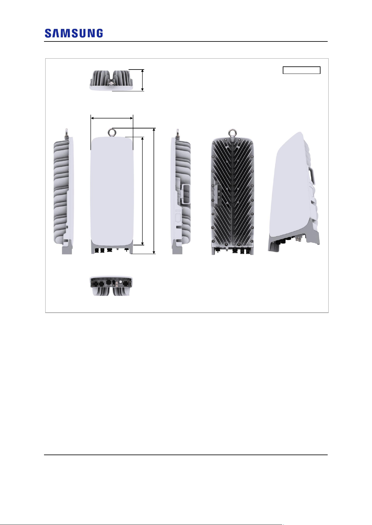
HRU View
The figure below depicts the physical structure of the HRU:
Page 17
Confidential
Chapter 1 Before Installation
5G NR HRU Installation Manual v1.0 2
Copyright © 2018, All Rights Reserved.
Figure 1. HRU View
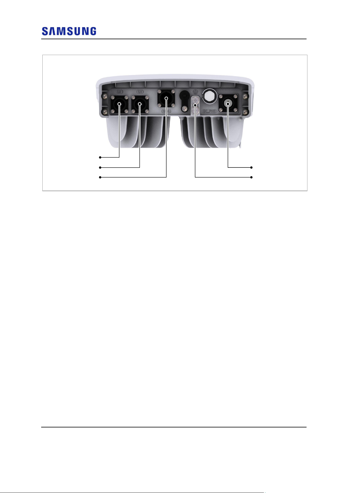
HRU External Interface
The figure below depicts the external interface structure of the HRU:
Unit: in. (mm)
[Left View]
[Front View]
25.27 (641.9)
29.09 (739)
4.65
(118.2)
[Bottom View]
[Right View]
[Rear View]
10.04 (255)
[Top View]
Page 18
Confidential
Chapter 1 Before Installation
5G NR HRU Installation Manual v1.0 3
Copyright © 2018, All Rights Reserved.
Figure 2. HRU External Interface
L0
L1
UDA
DC_PWR
Ground Terminal
[Bottom View]
Page 19

Confidential
Chapter 1 Before Installation
5G NR HRU Installation Manual v1.0 4
Copyright © 2018, All Rights Reserved.
Specifications
The table below outlines the main specifications of the HRU:
Table 1. Specifications
Item
SFG-AB203
Technology
5G NR
Operating Frequency
27.5 to 28.35 GHz
Channel Bandwidth
100 MHz
Operating Bandwidth
100 MHz × 8 Carrier
Antenna Configuration
Integrated Antenna
Data Channel: 4Tx/4Rx
RF chain per Data Channel: 256 (Total 1024 RF Chains/Unit)
RF Output Power
EIRP 54 dBm/Path, 60 dBm/Unit (Antenna Gain: 24 dBi)
Input Voltage
-48 V DC (-36 to -58 V DC)
Input Current
5.4 A @ -48 V DC
LED
Total: 1 EA
Powered, Operational, Fail (3 Status w/different colors)
Operational
Temperature
-40 to 55°C
Humidity
-5 to 100 % RH, condensing, not to exceed 30 g/m3 absolute
humidity
IP rating
IP65
EMC
FCC Part 15
FCC
FCC Part 30
Installation
Pole/Wall/Tower mounting
Dimension (W × D × H)
25.27 in. (641.9 mm) × 10.04 in. (255.0 mm) × 4.65 in. (118.2
mm)
Volume
< 19.3 L
Weight
< 37.48 lb (17.0 kg)
Page 20
Confidential
Chapter 1 Before Installation
5G NR HRU Installation Manual v1.0 5
Copyright © 2018, All Rights Reserved.
Cautions for Installation
Observe the safety instructions described in this section when installing the
system.
Installation should be done in accordance with the applicable local electric codes.
Before Installing
Before starting the installation, ensure the following:
Post warning signs in areas where high-voltage cables are installed.
Post ‘off limit’ signs in areas where accidents are most expected.
Use guardrails or fences to block open areas such as ditches, open roof areas,
and scaffolds.
Install the system in the restricted access area.
While Installing
During installation, ensure the following:
The system power must be cut off before installing.
Ensure that the power switch of the power supply is off when installing the system.
Installing the system with power on may cause system damage or fatal human
injury when connecting or disconnecting cables.
Ensure that workers wear protection gloves and goggles to prevent injury from
debris while drilling holes in a wall or ceiling.
Do not wear accessories such as watches and rings to prevent electrical shock.
Cover unused ports with a cap. This prevents foreign substances from entering into
the unused ports.
To prevent foreign substances, outdoor air, and moisture from entering the cable
inlet (including cable gland and conduit), finish the inlet as follows:
- Unused inlet: Use the hole finishing materials including cap and rubber packing.
- Cable-installed inlet: After cable installation, block any space in the inlet with
tape, compressed sponge, rubber packing, and silicone.
After Installing
After installation, remove any debris produced during the work and clean up the
installation site.
Page 21

Confidential
Chapter 1 Before Installation
5G NR HRU Installation Manual v1.0 6
Copyright © 2018, All Rights Reserved.
In the system, the laser beam light runs through the optical cable. The workers
must handle the optical cables with care as the laser beam can seriously damage
the eyes.
Ensure that the workers do not damage installed cables while cleaning the system.
While cleaning the power supply device, take precaution that the device does not
come in contact with foreign objects that may cause power failure.
Page 22
Confidential
Chapter 1 Before Installation
5G NR HRU Installation Manual v1.0 7
Copyright © 2018, All Rights Reserved.
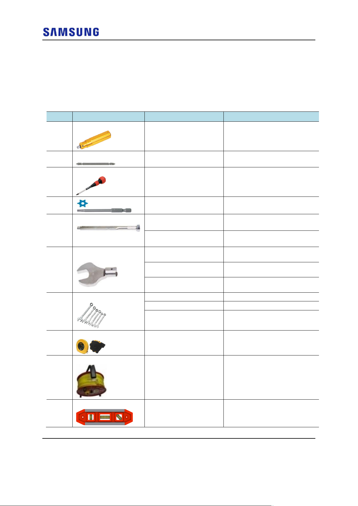
Installation Tools
The basic tools required for installation are listed in the table below. The
additional tools required for each site need to be identified and arranged during a
site survey before starting the installation.
Table 2. Basic Installation Tools
Number
Name
Specification
Purpose of use
1
Torque Driver
Apply a torque range
: 20 to 90 lbf·in
Fastening M6 SEMS
2
Screw Driver Bit
+, No. 3
Fastening M6 SEMS
3
Screw Driver
+, No. 3
Loosening M6 SEMS
4 T30H
Fastening Torx Screw (T30H)
5
Torque Wrench
Apply a torque range
: 10 to 50 lbf·in
Tightening M6 hexagonal. bolt
Apply a torque range
: 100 to 400 lbf·in
Tightening M8 and M10 hexagonal.
bolt
6
Torque Wrench Spanner
Head
Apply hexagonal bolt head:
10 mm (for 10 to 50 lbf·in)
Tightening M6 hexagonal bolt
Apply hexagonal bolt head:
13 mm (for 100 to 400 lbf·in)
Tightening M8 hexagonal bolt
Apply hexagonal bolt head:
17 mm (for 100 to 400 lbf·in)
Tightening M10 hexagonal nut
7
Spanner
10 mm
Loosening M6 hexagonal bolt
13 mm
Loosening M8 hexagonal. bolt
17 mm
Tightening M10 hexagonal nut
8
Tape Measure
16 ft./150 ft.
Measuring length
9
Power Extension Cable
100 ft.
Basic tool
10
Level
Normal
Levelling horizontality and verticality
Page 23
Confidential
Chapter 1 Before Installation
5G NR HRU Installation Manual v1.0 8
Copyright © 2018, All Rights Reserved.
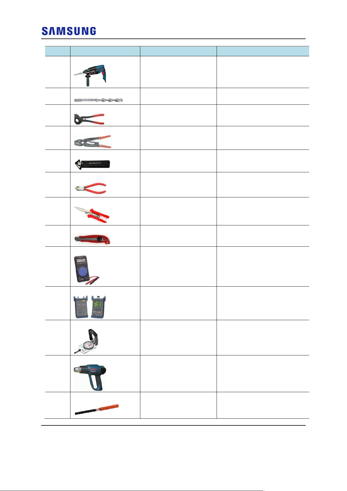
Number
Name
Specification
Purpose of use
11
Hammer Drill
Normal
Drilling wall
12
Concrete Drill Bit
14 mm
Setting M10 Anchor
13
Cable Cutter
0.24-1.26 in. (6-32 mm)
Cutting cable
14
Crimping Tool
14 AWG-4 AWG (1.5 to 16
mm2)
Crimping pressure terminal
15
Wire Stripper
Apply cable thickness: 1.5 to
6.2 in. (4 to 16 mm)
Removing cable sheath
16
Nipper
Basic Tool
Cutting cable
17
Industrial Scissor
Basic Tool
Cutting
18
Knife
Basic Tool
Cutting
19
Multi tester
Digital Pocket Tester
Checking voltage and current to
detect cable disconnection
20
Fiber Optical Test Set
Wave length: 1310 nm, 1550
nm (single mode) 850 nm,
1310 nm (multi-mode)
Checking optical level
21
Compass
Normal
Checking azimuth during installation
22
Heating Gun
50°C to 300°C
Shrinking the feeder cable tube
23
Anchor Punch
M10
Setting M10 anchor
Page 24

Confidential
Chapter 1 Before Installation
5G NR HRU Installation Manual v1.0 9
Copyright © 2018, All Rights Reserved.
Number
Name
Specification
Purpose of use
24
Hammer
Normal
Fixing anchor
25
MPO Cleaning Tool
FUJIOPTICS
(Part No.: CLE-ELE-1.25/2.5)
Cleaning MPO connector
The required installation tools may vary depending on the site conditions.
In addition to the basic tools, protractor, ladder, safety equipment, and cleaning
tools must also be arranged, considering the site conditions.
Page 25
Confidential
5G NR HRU Installation Manual v1.0 10
Copyright © 2018, All Rights Reserved.
Chapter 2 Installing System
This chapter describes the installation procedures of the HRU.
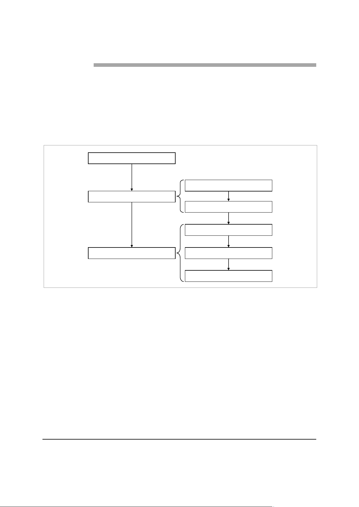
Installation Procedure
The figure below depicts the overall procedures for installing the HRU:
Figure 3. Procedure to Install the HRU
Foundation Work
Unpacking and Transporting
Fixing System
Unpacking Items
Bringing in Items
Fixing Unit Bracket
Fixing Mounting Bracket
Fixing HRU
Page 26
Confidential
Chapter 2 Installing System
5G NR HRU Installation Manual v1.0 11
Copyright © 2018, All Rights Reserved.
System Arrangement
A minimum distance must be secured around the HRU, in each direction for
installation and maintenance.
The recommended clearance for installing the HRU is as follows.
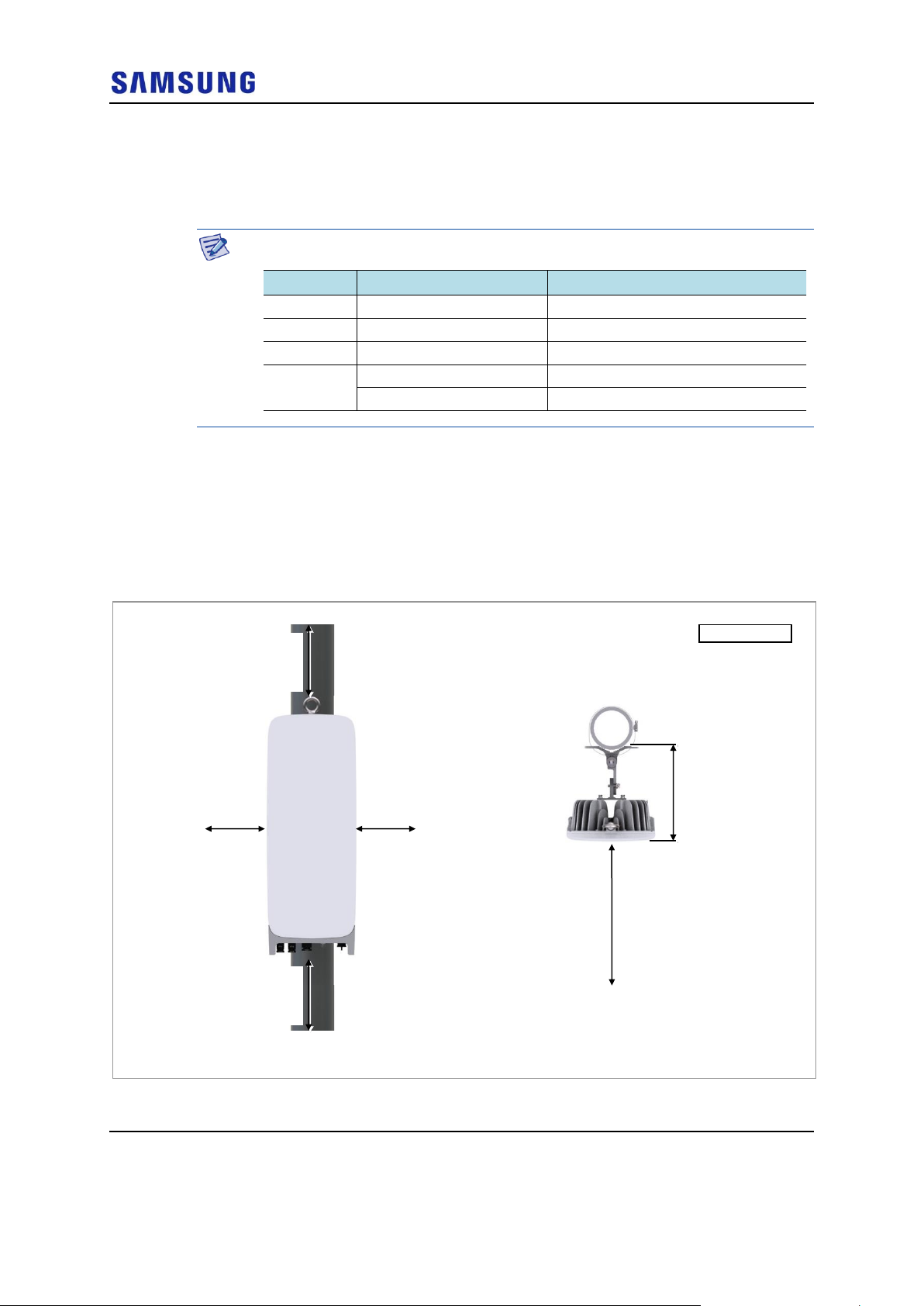
Using Tilting and Swiveling Bracket
The figures below depict the recommended distances for each direction of the
HRU using the tilting and swiveling bracket for the wall and the pole type
installations:
Figure 4. HRU Arrangement_1 Sector Pole Type Installation
Category
Recommended Distances
Remarks
Front
≥ 32 in. (800 mm)
-
Sides
≥ 8 in. (200 mm)
Standard Installation
Top
≥ 12 in. (300 mm)
-
Bottom
≥ 12 in. (300 mm)
Over the air, without cover
≥ 16 in. (400 mm)
Over the ground, without cover
Unit: in. (mm)
[Top View]
[Front View]
≥ 12 (300)
≥ 8 (200)
≥ 32 (800)
10.72 (272.2)
≥ 12 (300)
≥ 8 (200)
Page 27
Confidential
Chapter 2 Installing System
5G NR HRU Installation Manual v1.0 12
Copyright © 2018, All Rights Reserved.
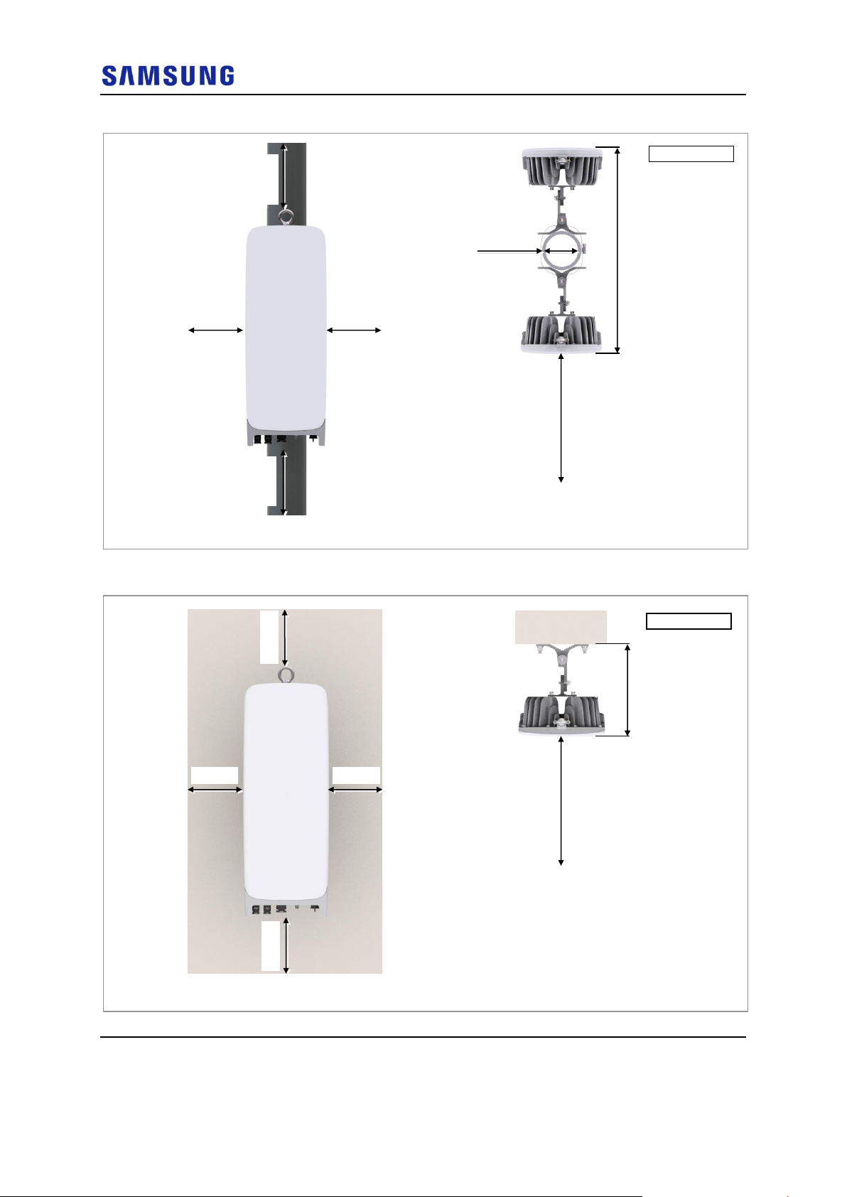
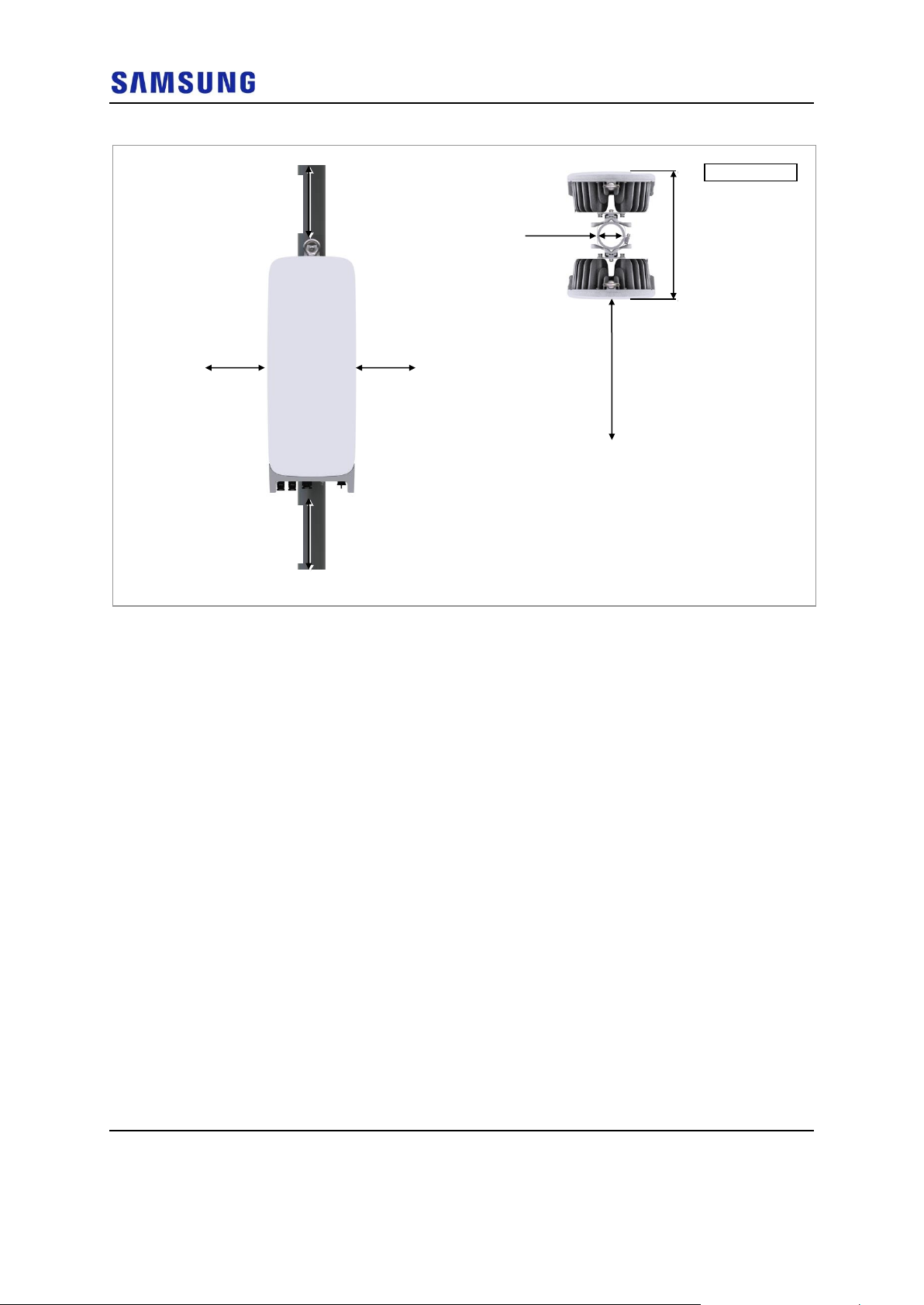
Figure 5. HRU Arrangement_2 Sector Pole Type Installation
Figure 6. HRU Arrangement_1 Sector Wall Type Installation
Unit: in. (mm)
[Top View]
[Front View]
≥ 12(300)
≥ 12(300)
≥ 8 (200)
≥ 8 (200)
≥ 32 (800)
26.69(678)
6.45(165)
Unit: in. (mm)
[Top View]
[Front View]
≥ 8 (200)
≥ 12 (300)
≥ 8 (200)
≥ 32 (800)
10.72 (272.2)
Page 28
Confidential
Chapter 2 Installing System
5G NR HRU Installation Manual v1.0 13
Copyright © 2018, All Rights Reserved.
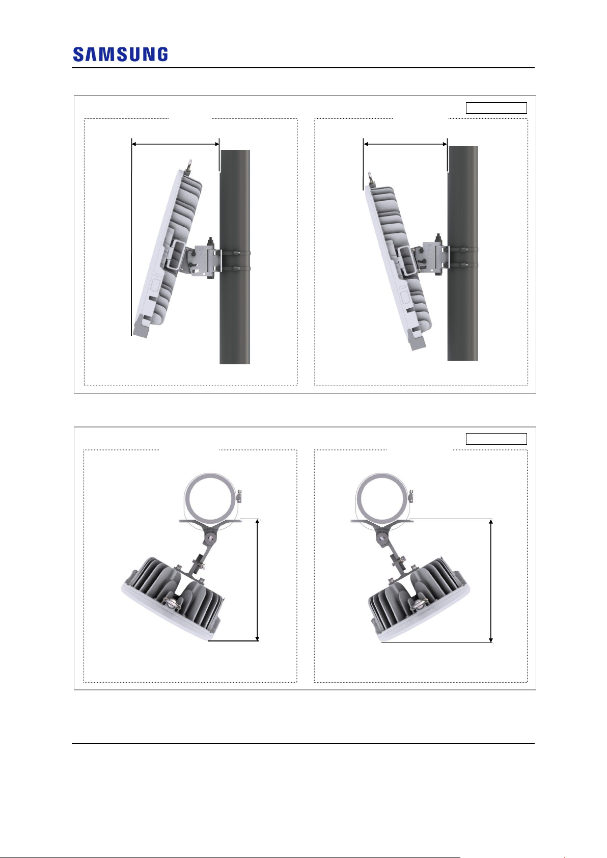
Figure 7. HRU Arrangement_Tilting
Figure 8. HRU Arrangement_Swiveling
Unit: in. (mm)
[Up Tilting]
[Right View]
[Down Tilting]
[Right View]
14.05 (357)
13.58 (345)
Unit: in. (mm)
[Left Swiveling]
[Top View]
[Right Swiveling]
[Top View]
11.61 (295)
11.61 (295)
Page 29
Confidential
Chapter 2 Installing System
5G NR HRU Installation Manual v1.0 14
Copyright © 2018, All Rights Reserved.
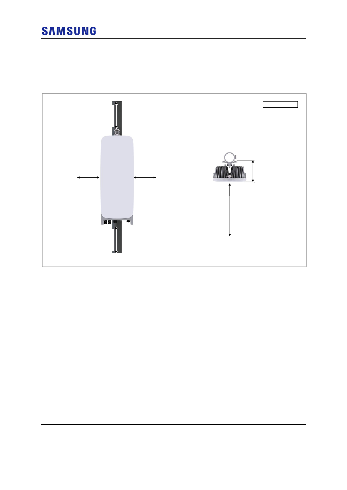
Without Tilting Bracket
The figures below depict the recommended distances for each direction of the
HRU without using the tilting bracket:
Figure 9. HRU Arrangement_1 Sector Pole Type Installation
Unit: in. (mm)
[Top View]
[Front View]
≥ 12 (300)
≥ 8 (200)
≥ 32 (800)
6.33
(160.7)
≥ 12 (300)
≥ 8 (200)
Page 30
Confidential
Chapter 2 Installing System
5G NR HRU Installation Manual v1.0 15
Copyright © 2018, All Rights Reserved.
Figure 10. HRU Arrangement_2 Sector Pole Type Installation
Using Chain Bracket
The figure below depicts the recommended distances for each direction of the
HRU using the chain bracket:
Unit: in. (mm)
[Top View]
[Front View]
≥ 12 (300)
≥ 8 (200)
≥ 32 (800)
17.36 (441)
≥ 12 (300)
≥ 8 (200)
6.45 (165)
Page 31

Confidential
Chapter 2 Installing System
5G NR HRU Installation Manual v1.0 16
Copyright © 2018, All Rights Reserved.
Figure 11. HRU Arrangement_3 Sector Pole Type Installation
Unit: in. (mm)
[Top View]
[Front View]
≥ 12 (300)
≥ 32 (800)
≥ 32 (800)
≥ 32 (800)
≥ 32 (800)
27.16 (690)
14 (355.6)
Page 32

Confidential
Chapter 2 Installing System
5G NR HRU Installation Manual v1.0 17
Copyright © 2018, All Rights Reserved.
Transporting and Unpacking
This section describes how to transport the items to the installation place and
provides the procedure to unpack cabinets and other components.
Bringing in Items
Ensure the following at each stage of transportation of the items:
Before moving a system, check storage place for the system and remove
obstacles in advance.
When carrying the system:
o Fasten the system firmly to the transport vehicle or carrier to prevent
damage to the system from a vibration or shock.
o Use an elevator to prevent accidents. However, if the system must be
carried by people, ensure there are enough people to carry the system.
The system must not be shocked physically.
The system should be protected from dust, moisture, and static electricity.
Unpacking
To unpack the items, ensure the following:
The items must be packed until they reach the installation place.
The items are classified in accordance with each job specification and stored at
a place that does not interfere with working.
Unpacked systems must be installed immediately. If immediate installation of
the systems is not planned, the systems must be stored in the installation place
temporarily.
Unpack only external packing, leaving the internal packing in unpacked status.
Unpack the inner packaging after each system is placed on its installation
location.
Dispose by-products (packaging waste) in accordance with waste management
rules. Do not recycle the by-products.
Page 33

Confidential
Chapter 2 Installing System
5G NR HRU Installation Manual v1.0 18
Copyright © 2018, All Rights Reserved.
HRU Handling
When transporting the HRU, hold the handle at the side of the HRU (no tool is
needed for holding the handle.). After finishing the HRU fixation, turn the handle
back.
The figure below depicts the position and direction of movement of the handle:
Figure 12. Using a Handle to transport an HRU
[Rear Side]
Handle
[Example: How to use]
1
2
Page 34

Confidential
Chapter 2 Installing System
5G NR HRU Installation Manual v1.0 19
Copyright © 2018, All Rights Reserved.
Fixing HRU
This section describes the procedures to fix the HRU by different methods.
Using Tilting and Swiveling Bracket
This section describes the procedure to fix the unit bracket using the tilting and
swiveling bracket.
Fixing Unit Bracket
These instructions for mounting a unit bracket to the HRU apply to all installation
types.
To fix the unit bracket, do the following:
Prerequisites
Before proceeding with fixing the unit bracket, make sure that you have the items
mentioned in the table below:
Table 3. Parts and Tools for Fixing Unit Bracket on HRU
Category
Description
Parts
Unit Bracket
1 EA/HRU
Fasteners
M6 × L20 hexagonal bolt (Washer
assembly)
4 EA/HRU
M8 × L30 hexagonal bolt (Washer
assembly)
1 EA/HRU
Recommended Torque Value
M6 Hex. Bolt
43 lbfin (50 kgf·cm)
Working Tools
Torque Wrench (10 to 50 lbfin)
Torque Wrench Spanner Head (apply hexagonal head: 10 mm)
Spanner (apply hexagonal head: 13 mm)
1 Inset the M8 hexagonal bolt to the unit bracket temporarily.
Page 35

Confidential
Chapter 2 Installing System
5G NR HRU Installation Manual v1.0 20
Copyright © 2018, All Rights Reserved.
Figure 13. Fixing Unit Bracket (1)
2 Check the position for mounting the unit bracket on the back of the HRU and
place it in that position.
Figure 14. Fixing Unit Bracket (2)
3 Fix the unit bracket using fasteners.
1
2
Unit Bracket
M8 Hex. Bolt
(Washer Assembly)
≒ 0.4 in. (10 mm)
* Keep the distance between the M8
Hex. Bolt and unit bracket by 0.4 in
(10 mm).
Unit Bracket
Fixing Point
1
2
Unit Bracket
[Rear Side]
Page 36

Confidential
Chapter 2 Installing System
5G NR HRU Installation Manual v1.0 21
Copyright © 2018, All Rights Reserved.
Figure 15. Fixing Unit Bracket (3)
Fixing Pole Type
This section describes the procedures for fixing the system on the pole.
The standard of the pole on which the mounting bracket can be attached using
steel bands is 50 A to 150 A (250 A is optional).
Assembling Mounting Bracket for 1 Sector
To assemble the mounting bracket for 1 sector, do the following:
Prerequisites
Before proceeding with assembling the mounting bracket for 1-sector, make sure
that you have the items mentioned in the table below:
Table 4. Parts and Tools for Fixing Mounting Bracket on the Pole
Category
Description
Parts
Mounting Bracket
1 EA
Fasteners
Steel Band
2 EA
Recommended Torque Value
Steel Band Fixing Screw
48.5 lbfin (56.1 kgfcm)
Working Tools
Torque Driver (20 to 90 lbfin)
Screw Driver Bit ('+', No. 3)
Compass
1 Pass the steel band through the fixing hole of the mounting bracket.
1
2
Unit Bracket
M6 Hex. Bolt
(Washer Assembly)
Page 37

Confidential
Chapter 2 Installing System
5G NR HRU Installation Manual v1.0 22
Copyright © 2018, All Rights Reserved.
Figure 16. Fixing Mounting Bracket on the Pole (1)
2 Use a compass to determine the azimuth of the HRU to be installed on the
pole.
Figure 17. Fixing Mounting Bracket on the Pole (2)
3 Place a mounting bracket to the pole.
1
2
Steel Band
Mounting Bracket
Pole
Compass
Page 38

Confidential
Chapter 2 Installing System
5G NR HRU Installation Manual v1.0 23
Copyright © 2018, All Rights Reserved.
Figure 18. Fixing Mounting Bracket on the Pole (3)
4 Fix the mounting bracket to the pole using the steel band.
Figure 19. Fixing Mounting Bracket on the Pole (4)
5 Check the level of mounting bracket on the pole and adjust the level.
1
2
Pole
1
2
3
4
Page 39

Confidential
Chapter 2 Installing System
5G NR HRU Installation Manual v1.0 24
Copyright © 2018, All Rights Reserved.
Figure 20. Fixing Mounting Bracket on the Pole (5)
When fixing the mounting bracket on the pole, be sure to check the level of
bracket. After finishing the installation, adjust the level minutely.
When poor leveling happens, adjust the position of fasteners used to fix the
mounting bracket.
After fixing the steel band, push the remainder of band inside the mounting
bracket
Lifting HRU
To lift the HRU, do the following:
1 Tie the rope in two carrying points of HRU.
If it is level, the bubble of the
spirit level is positioned at the
center of both lines.
Page 40

Confidential
Chapter 2 Installing System
5G NR HRU Installation Manual v1.0 25
Copyright © 2018, All Rights Reserved.
Figure 21. Lifting HRU (1)
2 While Operator A hauls the rope to carry up the HRU, Operator B pulls the
rope outward, so that HRU would not hit the tower platform.
3 Operator C locates the carried HRU to the installation position.
[Rear Side]
Carrying Point_1
For Eye Bolt
Carrying Point_2
For Handle
Carrying Point_1
For Eye Bolt
[Rear Side]
Page 41

Confidential
Chapter 2 Installing System
5G NR HRU Installation Manual v1.0 26
Copyright © 2018, All Rights Reserved.
Figure 22. Lifting HRU (2)
Fixing HRU on the Pole
To fix the HRU on the pole, do the following:
Prerequisites
Before proceeding with fixing the HRU on the pole, make sure that you have the
items mentioned in the table below:
Table 5. Parts and Tools for Fixing HRU on the Pole
Category
Description
Fasteners
M8 × L30 hexagonal bolt (Washer assembly)
1 EA
Recommended Torque Value
M8 hexagonal bolt
110 lbfin (127 kgf·cm)
Working Tools
Torque Wrench (100 to 400 lbfin)
Torque Wrench Spanner Head (apply hexagon head: 13 mm)
Compass
1 Place the unit bracket on the fixing groove of the mounting bracket.
Pulley
HRU
Tower Platform
Rope
Operator B
Operator A
Operator C
Page 42

Confidential
Chapter 2 Installing System
5G NR HRU Installation Manual v1.0 27
Copyright © 2018, All Rights Reserved.
Figure 23. Fixing HRU on the Pole (1)
2 Fix the HRU using fasters.
Fixing Groove
Mounting Bracket
Unit Bracket
1
2
Page 43

Confidential
Chapter 2 Installing System
5G NR HRU Installation Manual v1.0 28
Copyright © 2018, All Rights Reserved.
Figure 24. Fixing HRU on the Pole (2)
When installing the HRU, the tilting angle pointer of the unit bracket should point
to 0°.
3 Use the compass to check the azimuth of the front of the HRU.
M8 Hex. Bolt
(Washer Assembly)
1
2
[Angle pointer position for unit bracket with
0° tilt when installing the HRU]
Tilting angle scale of the unit bracket
Page 44

Confidential
Chapter 2 Installing System
5G NR HRU Installation Manual v1.0 29
Copyright © 2018, All Rights Reserved.
Figure 25. Fixing HRU on the Pole (3)
Assembling Mounting Bracket for 2 Sector
To assemble the mounting bracket for 2- sector, do the following:
Prerequisites
Before proceeding with assembling the mounting bracket for 2-sector, make sure
that you have the items mentioned in the table below:
Table 6. Parts and Tools for Fixing Mounting Bracket on the Pole
Category
Description
Parts
Mounting Bracket
2 EA
Fasteners
Steel Band
2 EA
Recommended Torque Value
Steel Band Fixing Screw
48.5 lbfin (56.1 kgfcm)
Working Tools
Torque Driver (20 to 90 lbfin)
Screw Driver Bit ('+', No. 3)
Compass
1 Pass the steel band through the fixing hole of the mounting brackets.
Compass
Page 45

Confidential
Chapter 2 Installing System
5G NR HRU Installation Manual v1.0 30
Copyright © 2018, All Rights Reserved.
Figure 26. Fixing Mounting Bracket on the Pole (1)
2 Use a compass to determine the azimuth of the HRU to be installed on the
pole.
1
2
Steel Band
Mounting Bracket
3
4
Page 46

Confidential
Chapter 2 Installing System
5G NR HRU Installation Manual v1.0 31
Copyright © 2018, All Rights Reserved.
Figure 27. Fixing Mounting Bracket on the Pole (2)
3 Place mounting brackets to the pole.
Figure 28. Fixing Mounting Bracket on the Pole (3)
4 Fix the mounting brackets to the pole using the steel band.
Pole
Compass
1
2
Pole
Page 47

Confidential
Chapter 2 Installing System
5G NR HRU Installation Manual v1.0 32
Copyright © 2018, All Rights Reserved.
Figure 29. Fixing Mounting Bracket on the Pole (4)
5 Check the level of each mounting brackets on the pole and adjust the level.
Figure 30. Fixing Mounting Bracket on the Pole (5)
When fixing the mounting bracket on the pole, ensure to check the level of
bracket. After finishing the installation, adjust the level minutely.
1
2
3
4
If it is level, the bubble of the
spirit level is positioned at the
center of both lines.
Page 48

Confidential
Chapter 2 Installing System
5G NR HRU Installation Manual v1.0 33
Copyright © 2018, All Rights Reserved.
When poor leveling happens, adjust the position of fasteners to fix the mounting
bracket.
After fixing the steel band, push the remainder of band inside the mounting
bracket
Lifting HRU
To lift the HRU, do the following:
1 Tie the rope in two carrying points of HRUs.
Figure 31. Lifting HRUs (1)
2 While Operator A hauls the rope to carry up the HRUs, Operator B pulls the
rope outward, so that HRUs do not hit the tower platform.
3 Operator C locates the carried HRU to the installation position.
[Rear Side]
Carrying Point_1
For Eye Bolt
Carrying Point_2
For Handle
Carrying Point_1
For Eye Bolt
[Rear Side]
Page 49

Confidential
Chapter 2 Installing System
5G NR HRU Installation Manual v1.0 34
Copyright © 2018, All Rights Reserved.
Figure 32. Lifting HRUs (2)
Fixing HRUs on the Pole
To fix the HRU on the pole, do the following:
Prerequisites
Before proceeding with fixing the HRU on the pole, make sure that you have items
mentioned in the following table.
Table 7. Parts and Tools for Fixing HRU on the Pole
Category
Description
Fasteners
M8 × L30 hexagonal bolt (Washer assembly)
1 EA/HRU
Recommended Torque Value
M8 hexagonal bolt
110 lbfin (127 kgf·cm)
Working Tools
Torque Wrench (100 to 400 lbfin)
Torque Wrench Spanner Head (apply hexagonal head: 13 mm)
Compass
1 Place the unit bracket of HRU-0 on the fixing groove of the mounting bracket.
Pulley
HRUs
Tower Platform
Rope
Operator B
Operator A
Operator C
Page 50

Confidential
Chapter 2 Installing System
5G NR HRU Installation Manual v1.0 35
Copyright © 2018, All Rights Reserved.
Figure 33. Fixing HRUs on the Pole (1)
2 Fix the HRU-0 using the fasters.
Fixing Groove
Mounting Bracket
Unit Bracket
HRU-0
HRU-0
HRU-0
1
2
Page 51

Confidential
Chapter 2 Installing System
5G NR HRU Installation Manual v1.0 36
Copyright © 2018, All Rights Reserved.
Figure 34. Fixing HRUs on the Pole (2)
When installing the HRU, the tilting angle pointer of the unit bracket should point
to 0°.
3 Place the unit bracket of HRU-1 on the fixing groove of the mounting bracket.
M8 Hex. Bolt
(Washer Assembly)
HRU-0
HRU-0
HRU-0
1
2
[Angle pointer position for unit bracket with
0° tilt when installing the HRU]
Tilting angle scale of the unit bracket
Page 52

Confidential
Chapter 2 Installing System
5G NR HRU Installation Manual v1.0 37
Copyright © 2018, All Rights Reserved.
Figure 35. Fixing HRUs on the Pole (3)
4 Fix the HRU-1 using the fasters.
Fixing Groove
Mounting Bracket
Unit Bracket
HRU-1
HRU-0
HRU-1
HRU-1
1
2
Page 53

Confidential
Chapter 2 Installing System
5G NR HRU Installation Manual v1.0 38
Copyright © 2018, All Rights Reserved.
Figure 36. Fixing HRUs on the Pole (4)
When installing the HRU, the tilting angle pointer of the unit bracket should point
to 0°.
5 Use the compass to check the azimuth of the front view of the HRU.
M8 Hex. Bolt
(Washer Assembly)
HRU-1
HRU-0
HRU-1
HRU-1
1
2
[Angle pointer position for unit bracket with
0° tilt when installing the HRU]
Tilting angle scale of the unit bracket
Page 54

Confidential
Chapter 2 Installing System
5G NR HRU Installation Manual v1.0 39
Copyright © 2018, All Rights Reserved.
Figure 37. Fixing HRUs on the Pole (5)
Fixing Wall Type
This section describes the procedures for fixing the system on the wall.
Fixing Mounting Bracket for 1 Sector
To fix the mounting bracket on the wall, do the following:
Prerequisites
Before proceeding with fixing the mounting bracket for 1-sector on the wall, make
sure that you have the items mentioned in the table below:
Table 8. Tools for Marking
Category
Description
Working Tools
Tape Measure
Permanent Maker
Level
To mount the system on a wall, perform the leveling test by referring to the
Compass
Page 55

Confidential
Chapter 2 Installing System
5G NR HRU Installation Manual v1.0 40
Copyright © 2018, All Rights Reserved.
System Leveling to check the positions are marked to be horizontal or vertical
before drilling. If the result shows they are not horizontal or vertical, modify the
marking positions.
When the position where the system will be placed is determined, place the system
on that position and then mark the positions where anchor bolts will be fixed. This
will reduce marking error range.
1 Check the distance between the location for fixing the HRU and the anchor
bolt hole.
Figure 38. HRU Marking Dimensions
2 Place a mounting bracket on the fixing location, and then check the level status
using a level and adjust the level of bracket assembly.
3 If the level status is normal, mark the anchor bolt holes on a wall.
: Anchor Bolt Hole
Unit: in (mm).
[Rear View]
15.30 (338.7)
29.09 (739)
10.04 (255)
2.46 (62.5)
2.46 (62.5)
5.12 (130)
Page 56

Confidential
Chapter 2 Installing System
5G NR HRU Installation Manual v1.0 41
Copyright © 2018, All Rights Reserved.
Figure 39. Marking
To drill an anchor hole, do the following:
Prerequisites
Before proceeding with the drilling process, make sure that you have items
mentioned in the following table
Table 9. Parts and Tools for Drilling
Category
Description
Woking Tools
Hammer Drill
Concrete Drill Bit (14 mm)
Vacuum Cleaner
Table 10. Anchor Bolt Drill Bits and Hole Depth
Category
Anchor Bolt
Drill Bits
Hole Depth
HRU (Wall Type)
M10
14 mm
44 mm
4 Drill the anchor holes at the marked points.
Remove dust from the holes using a vacuum cleaner.
[O]
* Remove the debris from the drilled hole.
[Anchor Hole Cross Section]
44 mm
[X]
14 mm
5.12 (130)
If it is level, the bubble of the
spirit level is positioned at the
center of both lines.
Unit: in (mm)./ : Marking Point
Page 57

Confidential
Chapter 2 Installing System
5G NR HRU Installation Manual v1.0 42
Copyright © 2018, All Rights Reserved.
Figure 40. Drilling
Fixing Mounting Bracket on the Wall
To fix the mounting bracket on the wall, do the following:
Prerequisites
Before proceeding with fixing the mounting bracket for 1-sector on the wall,
ensure that you have the items mentioned in the table below:
Table 11. Parts and Tools for Fixing Mounting Bracket on the Wall
Category
Description
Parts
Mounting Bracket
1 EA
Fasteners
M10 Set Anchor Assembly
M10 Set Anchor
M10 Plain Washer
M10 Spring Washer
M10 Hex. Nut
2 Set
1 EA/set
1 EA/set
1 EA/set
1 EA/set
Recommended Torque Value
M10 Hex. Nut
217 lbfin (250 kgfcm)
Working Tools
Torque Wrench (100 to 400 lbf·in)
Torque Wrench Spanner head (apply hexagonal. head: 17 mm)
Spanner (17 mm)
Hammer
Anchor Punch (for M10 set anchor bolt)
1 Fix the anchor to the drilled hole.
14 mm
Hammer Drill
Vacuum Cleaner
Page 58

Confidential
Chapter 2 Installing System
5G NR HRU Installation Manual v1.0 43
Copyright © 2018, All Rights Reserved.
Figure 41. Fixing Mounting Bracket on the Wall (1)
2 Place the mounting bracket on the wall and fix it using fasteners.
Figure 42. Fixing Mounting Bracket on the Wall (2)
Fixing HRU on the Wall
To fix the HRU on the wall, do the following:
Prerequisites
Before proceeding with fixing the HRU on the wall, ensure that you have the items
mentioned in the table below:
M10 Set Anchor
Anchor Punch
Hammer
1
2
M10 Set Anchor
Mounting Bracket
M10 Plain Washer
M10 Spring Washer
M10 Hex. Nut
1
2
Page 59

Confidential
Chapter 2 Installing System
5G NR HRU Installation Manual v1.0 44
Copyright © 2018, All Rights Reserved.
Table 12. Parts and Tools for Fixing HRU on the Wall
Category
Description
Fasteners
M8 × L30 hexagonal bolt (Washer assembly)
1 EA
Recommended Torque Value
M8 hexagonal bolt
110 lbfin (127 kgf·cm)
Working Tools
Torque Wrench (100 to 400 lbfin)
Torque Wrench Spanner Head (apply hexagonal head: 13 mm)
1 Place the unit bracket on the fixing groove of the mounting bracket.
Figure 43. Fixing HRU on the Wall (1)
2 Fix the HRU using the fasters.
Mounting Bracket
Fixing Groove
Unit Bracket
1
2
Page 60

Confidential
Chapter 2 Installing System
5G NR HRU Installation Manual v1.0 45
Copyright © 2018, All Rights Reserved.
Figure 44. Fixing HRU on the Wall (2)
Tilting
The instructions for tilting the HRU apply to all installation types.
The adjustable tilting range is as follows:
- Up tilting: 0° to 16°
- Down tilting: 0° to 16°
To adjust the HRU tilting, do the following:
Prerequisites
Before proceeding with adjusting the HRU tilting, make sure that you have the
items mentioned in the table below:
Table 13. Tools for Tilting HRU
Category
Description
Recommended Torque Value
M8 hexagonal bolt
110 lbfin (127 kgf·cm)
Working Tools
Torque Wrench (100 to 400 lbfin)
Torque Wrench Spanner Head (apply hexagonal head: 13 mm)
Spanner (13 mm)
M8 Hex. Bolt
(Washer Assembly)
1
2
Page 61

Confidential
Chapter 2 Installing System
5G NR HRU Installation Manual v1.0 46
Copyright © 2018, All Rights Reserved.
1 Loosen the HRU by turning M8 hexagonal bolt of mounting bracket two or
three times counterclockwise.
Do not separate it completely.
Figure 45. HRU Tilting Adjustment (1)
2 Pull the HRU up/down to adjust the tilting angle.
M8 Hex. Bolt
(Washer Assembly)
1
2
Page 62

Confidential
Chapter 2 Installing System
5G NR HRU Installation Manual v1.0 47
Copyright © 2018, All Rights Reserved.
Figure 46. HRU Tilting Adjustment (2)
3 Fix the HRU using the working tools.
[Down Tilting Adjustment]
[Up Tilting Adjustment]
Up tilting 16° Example
Down tilting 16° Example
Page 63

Confidential
Chapter 2 Installing System
5G NR HRU Installation Manual v1.0 48
Copyright © 2018, All Rights Reserved.
Figure 47. HRU Tilting Adjustment (3)
Swiveling
The instructions for swiveling the HRU apply to all installation types.
[Down Tilting Adjustment]
[Up Tilting Adjustment]
M8 Hex. Bolt
(Washer Assembly)
M8 Hex. Bolt
(Washer Assembly)
Page 64

Confidential
Chapter 2 Installing System
5G NR HRU Installation Manual v1.0 49
Copyright © 2018, All Rights Reserved.
The adjustable swiveling is as follows:
- Left Swiveling: 0° to 30°
- Right Swiveling: 0° to 30°
To adjust the HRU swivelling, do the following
Prerequisites
Before proceeding with swiveling the HRU, make sure that you have the items
mentioned in the table below:
Table 14. Tools for Swiveling HRU
Category
Description
Recommended Torque Value
M12 hexagonal nut
372 lbfin (428 kgf·cm)
Working Tools
Torque Wrench (100 to 400 lbfin)
Torque Wrench Spanner Head (apply hexagonal head: 19 mm)
Spanner (19 mm)
1 Loosen the HRU by turning M12 hexagonal nut of mounting bracket two or
three times counter clockwise.
Do not separate it completely.
Figure 48. HRU Swiveling Adjustment (1)
2 Pull the HRU left/right to adjust the swiveling angle.
M12 Hex. Nut
1
2
Page 65

Confidential
Chapter 2 Installing System
5G NR HRU Installation Manual v1.0 50
Copyright © 2018, All Rights Reserved.
Figure 49. HRU Swiveling Adjustment (2)
3 Fix the HRU using working tools.
[Right Swiveling Adjustment]
[Left Swiveling Adjustment]
[Left Swiveling 30° Example]
[Right Swiveling 30° Example]
Page 66

Confidential
Chapter 2 Installing System
5G NR HRU Installation Manual v1.0 51
Copyright © 2018, All Rights Reserved.
Figure 50. HRU Swiveling Adjustment (3)
Without the Tilting Bracket
This section describes the procedures to fix the unit bracket and the mounting
bracket.
[Right Swiveling Adjustment]
[Left Swiveling Adjustment]
M12 Hex. Nut
M12 Hex. Nut
Page 67

Confidential
Chapter 2 Installing System
5G NR HRU Installation Manual v1.0 52
Copyright © 2018, All Rights Reserved.
Fixing Unit Bracket
The instructions for mounting a unit bracket to the HRU apply to all installation
types.
To fix the unit bracket without tilting bracket, do the following:
Prerequisites
Before proceeding with fixing the unit bracket on the HRU, make sure that you
have the items mentioned in the table below:
Table 15. Parts and Tools for Fixing Unit Bracket on HRU
Category
Description
Parts
Unit Bracket
1 EA/HRU
Fasteners
M6 × L20 hexagonal bolt (Washer
assembly)
4 EA/HRU
Recommended Torque Value
M6 hexagonal bolt
43 lbfin (50 kgf·cm)
Working Tools
Torque Wrench (10 to 50 lbfin)
Torque Wrench Spanner Head (apply hexagon head: 10 mm)
1 Check the position for mounting the unit bracket on the back of the HRU and
place it in that position.
Figure 51. Fixing Unit Bracket (1)
2 Fix the unit bracket using the fasteners.
Unit Bracket
Fixing Point
1
2
Unit Bracket
[Rear Side]
Page 68

Confidential
Chapter 2 Installing System
5G NR HRU Installation Manual v1.0 53
Copyright © 2018, All Rights Reserved.
Figure 52. Fixing Unit Bracket (2)
Fixing Pole Type
The standard of the pole on which the mounting bracket can be attached using
steel bands is 50 A to 150 A.(250 A is optional)
Fixing Mounting Bracket for 1 sector
To fix the mounting bracket on the pole, do the following:
Prerequisites
Before proceeding with fixing the mounting bracket for 1-sector wall type, make
sure that you have the items mentioned in the table below:
Table 16. Parts and Tools for Fixing Mounting Bracket on the Pole
Category
Description
Parts
Mounting Bracket
1 EA
Fasteners
Steel Band
2 EA
Recommended Torque Value
Steel Band Fixing Screw
48.5 lbfin (56.1 kgfcm)
Working Tools
Torque Driver (20 to 90 lbfin)
Screw Driver Bit ('+', No. 3)
Compass
1 Pass the steel band through the fixing hole of the mounting bracket.
1
2
Unit Bracket
M6 Hex. Bolt
(Washer Assembly)
Page 69

Confidential
Chapter 2 Installing System
5G NR HRU Installation Manual v1.0 54
Copyright © 2018, All Rights Reserved.
Figure 53. Fixing Mounting Bracket on the Pole (1)
2 Use the compass to determine the azimuth of the HRU to be installed on the
pole.
Figure 54. Fixing Mounting Bracket on the Pole (2)
3 Place the mounting bracket to the pole.
1
2
Steel Band
Mounting Bracket
Pole
Compass
Page 70

Confidential
Chapter 2 Installing System
5G NR HRU Installation Manual v1.0 55
Copyright © 2018, All Rights Reserved.
Figure 55. Fixing Mounting Bracket on the Pole (3)
4 Fix the mounting bracket to the pole using the steel band.
Figure 56. Fixing Mounting Bracket on the Pole (4)
5 Check the level of mounting bracket on the pole and adjust the level.
1
2
Pole
1
2
3
4
Page 71

Confidential
Chapter 2 Installing System
5G NR HRU Installation Manual v1.0 56
Copyright © 2018, All Rights Reserved.
Figure 57. Fixing Mounting Bracket on the Pole (5)
When fixing the mounting bracket on the pole, be sure to check the level of
bracket. After finishing the installation, adjust the level minutely.
When poor leveling happens, adjust the position of fasteners used to fix the
mounting bracket.
After fixing the steel band, push the remainder of band inside the mounting
bracket
Lifting HRU
To lift the HRU, do the following:
1 Tie the rope in two carrying points of the HRU.
If it is level, the bubble of the
spirit level is positioned at the
center of both lines.
Page 72

Confidential
Chapter 2 Installing System
5G NR HRU Installation Manual v1.0 57
Copyright © 2018, All Rights Reserved.
Figure 58. Lifting HRU (1)
2 While Operator A hauls the rope to carry up the HRU, Operator B pulls the
rope outward, so that the HRU would not hit the tower platform.
3 Operator C locates the carried HRU to the installation position.
[Rear Side]
Carrying Point_1
For Eye Bolt
Carrying Point_2
For Handle
Carrying Point_1
For Eye Bolt
[Rear Side]
Page 73

Confidential
Chapter 2 Installing System
5G NR HRU Installation Manual v1.0 58
Copyright © 2018, All Rights Reserved.
Figure 59. Lifting HRU (2)
Fixing HRU on the Pole
To fix the HRU on the pole, do the following:
Prerequisites
Before proceeding with fixing the HRU on the pole, make sure that you have the
items mentioned in the table below:
Table 17. Tools for Fixing HRU on the Pole
Category
Description
Recommended Torque Value
M6 Torx Screw
43 lbfin (50 kgf·cm)
Working Tools
Torx Driver Bit (T30H)
Torque Driver (20 to 90 lbf·in)
Compass
1 Pull out the fastening materials so that they do not get out from the fixing
groove of the unit bracket.
Do not pull out completely.
Pulley
HRU
Tower Platform
Rope
Operator B
Operator A
Operator C
Page 74

Confidential
Chapter 2 Installing System
5G NR HRU Installation Manual v1.0 59
Copyright © 2018, All Rights Reserved.
Figure 60. Fixing HRU on the Pole (1)
2 Place the unit bracket on the fixing grooves of the mounting bracket and push
the unit bracket down to fix the HRU in place.
[Top View]
M6 Torx Screw
Unit Bracket
2
1
Page 75

Confidential
Chapter 2 Installing System
5G NR HRU Installation Manual v1.0 60
Copyright © 2018, All Rights Reserved.
Figure 61. Fixing HRU on the Pole (2)
3 Fix the unit bracket to the mounting bracket using the fastener.
Unit Bracket
Mounting Bracket
Unit Bracket
Mounting Bracket
1
2
Page 76

Confidential
Chapter 2 Installing System
5G NR HRU Installation Manual v1.0 61
Copyright © 2018, All Rights Reserved.
Figure 62. Fixing HRU on the Pole (3)
4 Use the compass to check the azimuth of the front of the HRU.
Figure 63. Fixing HRU on the Pole (4)
Fixing Mounting Bracket for 2 Sector
To fix the mounting bracket on the pole, do the following:
Unit Bracket
M6 Torx Screw
Mounting Bracket
1
2
Compass
Page 77

Confidential
Chapter 2 Installing System
5G NR HRU Installation Manual v1.0 62
Copyright © 2018, All Rights Reserved.
Prerequisites
Before proceeding with fixing the mounting bracket 2 sector pole type, make sure
that you have the items mentioned in the table below:
Table 18. Parts and Tools for Fixing Mounting Bracket on the Pole
Category
Description
Parts
Mounting Bracket
2 EA
Fasteners
Steel Band
2 EA
Recommended Torque Value
Steel Band Fixing Screw
48.5 lbfin (56.1 kgfcm)
Working Tools
Torque Driver (20 to 90 lbfin)
Screw Driver Bit ('+', No. 3)
Compass
1 Pass the steel band through the fixing hole of the mounting brackets.
Page 78

Confidential
Chapter 2 Installing System
5G NR HRU Installation Manual v1.0 63
Copyright © 2018, All Rights Reserved.
Figure 64. Fixing Mounting Bracket on the Pole (1)
2 Use a compass to determine the azimuth of the HRU to be installed on the
pole.
1
2
3
4
Steel Band
Mounting Bracket
Page 79

Confidential
Chapter 2 Installing System
5G NR HRU Installation Manual v1.0 64
Copyright © 2018, All Rights Reserved.
Figure 65. Fixing Mounting Bracket on the Pole (2)
3 Place the mounting brackets to the pole.
Figure 66. Fixing Mounting Bracket on the Pole (3)
4 Fix the mounting brackets to the pole using the steel band.
Pole
Compass
1
2
Pole
Page 80

Confidential
Chapter 2 Installing System
5G NR HRU Installation Manual v1.0 65
Copyright © 2018, All Rights Reserved.
Figure 67. Fixing Mounting Bracket on the Pole (4)
5 Check the level of each mounting brackets on the pole and adjust the level.
Figure 68. Fixing Mounting Bracket on the Pole (5)
When fixing the mounting bracket on the pole, ensure to check the level of
bracket. After finishing the installation, adjust the level minutely.
1
2
3
4
If it is level, the bubble of the
spirit level is positioned at the
center of both lines.
Page 81

Confidential
Chapter 2 Installing System
5G NR HRU Installation Manual v1.0 66
Copyright © 2018, All Rights Reserved.
When poor leveling happens, adjust the position of fasteners used to fix the
mounting bracket.
After fixing the steel band, push the remainder of band inside the mounting
bracket
Lifting HRUs
To lift the HRU, do the following:
1 Tie the rope in two carrying points of the HRUs.
Figure 69. Lifting HRUs (1)
2 While Operator A hauls the rope to carry up the HRUs, Operator B pulls the
rope outward, so that the HRUs would not hit the tower platform.
[Rear Side]
Carrying Point_1
For Eye Bolt
Carrying Point_2
For Handle
Carrying Point_1
For Eye Bolt
[Rear Side]
Page 82

Confidential
Chapter 2 Installing System
5G NR HRU Installation Manual v1.0 67
Copyright © 2018, All Rights Reserved.
Figure 70. Lifting HRUs (2)
Fixing HRUs on the Pole
To fix the HRU on the pole, do the following:
Prerequisites
Before proceeding with fixing the HRU on the pole, make sure that you have the
items mentioned in the table below:
Table 19. Tools for Fixing HRUs on the Pole
Category
Description
Recommended Torque Value
M6 Torx Screw
43 lbfin (50 kgf·cm)
Working Tools
Torx Driver Bit (T30H)
Torque Driver (20 to 90 lbf·in)
Compass
1 Pull out the fastening materials so that they do not jut out from the fixing
groove of the unit bracket.
Do not pull out completely.
Pulley
HRUs
Tower Platform
Rope
Operator B
Operator A
Page 83

Confidential
Chapter 2 Installing System
5G NR HRU Installation Manual v1.0 68
Copyright © 2018, All Rights Reserved.
Figure 71. Fixing HRUs on the Pole (1)
2 Place the unit bracket on the fixing grooves of the mounting bracket and push
the unit bracket down to fix the HRU-0 in place.
[Top View]
M6 Torx Screw
Unit Bracket
HRU-0
HRU-1
2
1
Page 84

Confidential
Chapter 2 Installing System
5G NR HRU Installation Manual v1.0 69
Copyright © 2018, All Rights Reserved.
Figure 72. Fixing HRUs on the Pole (2)
3 Fix the unit bracket of the HRU-0 to the mounting bracket using the fastener.
Unit Bracket
Mounting Bracket
Unit Bracket
Mounting Bracket
HRU-0
HRU-0
HRU-0
1
2
Page 85

Confidential
Chapter 2 Installing System
5G NR HRU Installation Manual v1.0 70
Copyright © 2018, All Rights Reserved.
Figure 73. Fixing HRUs on the Pole (3)
4 Place the unit bracket on the fixing grooves of the mounting bracket and push
the unit bracket down to fix the HRU-1 in place.
Unit Bracket
M6 Torx Screw
Mounting Bracket
HRU-0
HRU-0
HRU-0
1
2
Page 86

Confidential
Chapter 2 Installing System
5G NR HRU Installation Manual v1.0 71
Copyright © 2018, All Rights Reserved.
Figure 74. Fixing HRUs on the Pole (4)
5 Fix the unit bracket of the HRU-1 to the mounting bracket using fastener.
Unit Bracket
Mounting Bracket
Unit Bracket
Mounting Bracket
HRU-1
HRU-1
HRU-1
HRU-0
1
2
Page 87

Confidential
Chapter 2 Installing System
5G NR HRU Installation Manual v1.0 72
Copyright © 2018, All Rights Reserved.
Figure 75. Fixing HRUs on the Pole (5)
6 Use the compass to check the azimuth of the front of the HRU.
Unit Bracket
M6 Torx Screw
Mounting Bracket
HRU-1
HRU-1
HRU-1
HRU-0
1
2
Page 88

Confidential
Chapter 2 Installing System
5G NR HRU Installation Manual v1.0 73
Copyright © 2018, All Rights Reserved.
Figure 76. Fixing HRUs on the Pole (6)
Using Chain Bracket
This section describes the procedures to fix the zero-bolt unit bracket and the HRU
on the pole.
Fixing Zero-Bolt Unit Bracket
The instructions for mounting a zero-bolt unit bracket to the HRU apply to all
installation types.
To fix the Zero-bolt unit bracket, do the following:
Prerequisites
Before proceeding with fixing the zero bolt unit bracket, make sure that you have
the items mentioned in the table below:
Table 20. Parts and Tools for Fixing Unit Bracket on HRU
Category
Description
Parts
Zero-Bolt Unit Bracket
1 EA/HRU
Fasteners
M6 × L20 Hex. Bolt (Washer assembly)
4 EA/HRU
Recommended Torque Value
M6 Hex. Bolt
43 lbfin (50 kgf·cm)
Working Tools
Torque Wrench (10 to 50 lbfin)
Torque Wrench Spanner Head (apply hexagon head: 10 mm)
Compass
Page 89

Confidential
Chapter 2 Installing System
5G NR HRU Installation Manual v1.0 74
Copyright © 2018, All Rights Reserved.
1 Check the position for mounting the zero-bolt unit bracket on the back of the
HRU and place it in that position.
Figure 77. Fixing Zero-Bolt Unit Bracket (1)
2 Fix the unit bracket using the fasteners.
Zero-Bolt
Unit Bracket
Fixing Point
1
2
Zero-Bolt
Unit Bracket
[Rear Side]
Page 90

Confidential
Chapter 2 Installing System
5G NR HRU Installation Manual v1.0 75
Copyright © 2018, All Rights Reserved.
Figure 78. Fixing Zero-Bolt Unit Bracket (2)
Fixing Pole Type
This section describes the procedure to fix the HRU on the pole.
Adjustment Chain Bracket Size for 3 Sector
After checking the size of the pole to install the chain bracket, add/remove the
module bracket of the chain bracket according to the size of the pole.
To adjust the chain bracket size, do the following:
Prerequisites
Before proceeding with adjusting the chain bracket size, make sure that you have
the items mentioned in the table below:
1
Zero-Bolt Unit Bracket
M6 Hex. Bolt
(Washer Assembly)
2
Pole Size
Module Bracket Quantity
125 A
4 EA
150 A
5 EA
200 A
6 EA
250 A
8 EA
300 A
9 EA
350 A
10 EA
Page 91

Confidential
Chapter 2 Installing System
5G NR HRU Installation Manual v1.0 76
Copyright © 2018, All Rights Reserved.
Table 21. Parts and Tools for Adjustment Chain Bracket Size
Category
Description
Parts
Chain Bracket Assembly
1 Set
Recommended Torque Value
M8 Hex. Bolt
110 lbfin (127 kgf·cm)
Working Tools
Torque Wrench (100 to 400 lbfin)
Torque Wrench Spanner Head (apply hexagon head: 13 mm)
Spanner (hexagon head: 13 mm)
Spanner (hexagon head: 17 mm)
1 Spread out the chain bracket assembly and place the hexagonal nuts in the
middle of the stud bolts.
Figure 79. Adjustment Chain Bracket Size (1)
2 Adjust the size of the chain bracket by adjusting the module bracket to match
the size of the pole.
Chain Bracket Assembly
M10 Hex. Nut
1
2 1 2
Page 92

Confidential
Chapter 2 Installing System
5G NR HRU Installation Manual v1.0 77
Copyright © 2018, All Rights Reserved.
Figure 80. Adjustment Chain Bracket Size (2)
Fixing Chain Bracket Assembly on the Pole
The following procedure is based on the 3 sector type that is installed on a 350 A
Module Bracket
M8 Hex. Bolt
(Washer Assembly)
M8 Hex. Bolt
(Washer Assembly)
1
2
3
1
2
1
2
3
Page 93

Confidential
Chapter 2 Installing System
5G NR HRU Installation Manual v1.0 78
Copyright © 2018, All Rights Reserved.
pole (OD: 14 in./355.6 mm).
To fix the chain bracket assembly on the pole, do the following:
Prerequisites
Before proceeding with fixing the chain bracket assembly on the pole, make sure
that you have the items mentioned in the table below:
Table 22. Parts and Tools for Fixing Chain Bracket Assembly on the Pole
Category
Description
Parts
Chain Bracket Assembly
1 Set
Recommended Torque Value
M10 Hexagonal nut
217 lbfin (250 kgf·cm)
Working Tools
Torque Wrench (100 to 400 lbfin)
Torque Wrench Spanner Head (apply hexagonal head: 17 mm)
Spanner (hexagon head: 17 mm)
1 Open the chain bracket assembly and place it in the position on the pole where
the HRUs are to be installed.
Figure 81. Fixing Chain Bracket Assembly on the Pole (1)
2 Fix the chain bracket assembly in place temporarily using the hexagonal nuts
on each side of the stud bolt.
Chain Bracket Assembly
1
2
Page 94

Confidential
Chapter 2 Installing System
5G NR HRU Installation Manual v1.0 79
Copyright © 2018, All Rights Reserved.
Figure 82. Fixing Chain Bracket Assembly on the Pole (2)
The extra space on each side of the stud bolt (A) must be equal when temporarily
fixing the chain bracket assembly in place.
3 Use the hexagonal nut in the centre of the stud bolt to fix the clamp nut-2 in
place.
Cork
M10 Hex. Nut
1
2
3
≒ A
≒ A
Page 95

Confidential
Chapter 2 Installing System
5G NR HRU Installation Manual v1.0 80
Copyright © 2018, All Rights Reserved.
Figure 83. Fixing Chain Bracket Assembly on the Pole (3)
4 Check the level of chain bracket assembly on a pole and adjust the level.
Figure 84. Fixing Chain Bracket Assembly on the Pole (4)
When fixing the chain bracket assembly on the pole, ensure to check the level of
bracket. After finishing the installation, adjust the level minutely.
If the leveling is poor, adjust the position of fasteners used to fix the chain bracket
assembly.
Lifting HRU
To lift the HRU, do the following:
M10 Hex. Nut
Clamp Nut-2
1
2
Off-the-ground work
If it is level, the bubble of the
spirit level is positioned at the
center of both lines.
Page 96

Confidential
Chapter 2 Installing System
5G NR HRU Installation Manual v1.0 81
Copyright © 2018, All Rights Reserved.
1 Tie the rope in two carrying points of the HRU.
Figure 85. Lifting HRUs (1)
2 While Operator A hauls the rope to carry up the HRUs, Operator B pulls the
rope outward, so that the HRU would not hit the tower platform.
[Rear Side]
Carrying Point_1
For Eye Bolt
Carrying Point_1
For Eye Bolt
[Rear Side]
Carrying Point_2
For Handle
Page 97

Confidential
Chapter 2 Installing System
5G NR HRU Installation Manual v1.0 82
Copyright © 2018, All Rights Reserved.
Figure 86. Lifting HRUs (2)
Fixing HRUs on the Pole
Check the location for installing the HRU for each module before mounting the
chain bracket to the HRU.
To fix the HRU on the pole, do the following:
1 Place the zero-bolt unit bracket on the fixing grooves of the chain bracket and
push the zero-bolt bracket down until it clicks to fix the HRU-0 in place.
Pulley
HRUs
Tower Platform
Rope
Operator A
Operator B
[Example: Mounting location for each HRU]
HRU-0
Fixing Point
HRU-2
Fixing Point
HRU-1
Fixing Point
Page 98

Confidential
Chapter 2 Installing System
5G NR HRU Installation Manual v1.0 83
Copyright © 2018, All Rights Reserved.
Figure 87. Fixing HRUs on the Pole (1)
2 Fix the HRU-1 and HRU-2 using the same method.
HRU-0
Zero-Bolt
Unit Bracket
Chain Bracket
Module
HRU-0
HRU-0
Zero-Bolt
Unit Bracket
Chain Bracket
Module
1
2
Page 99

Confidential
Chapter 2 Installing System
5G NR HRU Installation Manual v1.0 84
Copyright © 2018, All Rights Reserved.
Figure 88. Fixing HRUs on the Pole (2)
HRU-0
HRU-1
HRU-0
HRU-1
HRU-2
1
2
Page 100

Confidential
5G NR HRU Installation Manual v1.0 85
Copyright © 2018, All Rights Reserved.
Chapter 3 Connecting
Cables
This chapter describes the procedures to connect cables to the HRU system and to
label the cables.
Cabling Procedure
The figure below depicts the procedure to connect system cables:
Figure 89. Procedure to Connect System Cable
Grounding
Power Cabling
Connecting Ground Cable
Interface Cable Connection
Connecting Link Cable
Connecting UDA Cable
Connecting Power Cable
 Loading...