

Samsung HG32ED470S, HG32ED450S, HG32AD470S, HG32AD450S User Manual

LED TV
Installation manual
450S/470S
imagine the possibilities
Thank you for purchasing this Samsung product.
To receive more complete service, please
register your product at
www.samsung.com/register
Model Serial No.
Figures and illustrations in this User Manual are provided for reference only and may differ from actual product
appearance. Product design and specifications may be changed without notice.
Instruction
This TV is provided with interactive functionality through a set-back box (SBB/STB) connected to the TV, and with other TVs in a
computer controlled system for hotels and other hospitality businesses.
Interactive: When the TV is powered-up initially, it sends a command to identify the SBB/STB. If identified, the TV switches to
ONLINE mode and full control is through the SBB/STB. (Only for HD470S)
If the TV is in ONLINE mode, it stops receiving IR (Samsung remote) commands and acts according to the interface protocol.
Stand-Alone: If SBB/STB is not identified, the TV should be switched to STAND-ALONE mode with restricted operations.
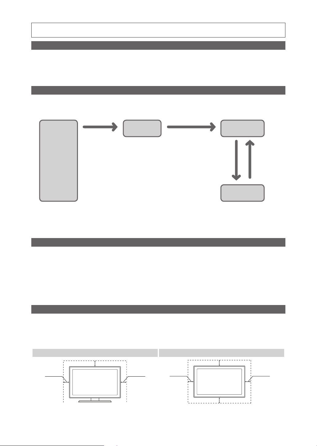
Operational Modes
When this TV (in Hotel mode) is operated with a SBB/STB, it is in one of two states:
• ONLINE or STAND-ALONE. In the STAND-ALONE state, the TV will act as a Hotel TV, but without active communication.
This prevents guests from trying to cheat the system by disconnecting the SBB/STB.
Power
ON
Hotel Mode On
Hotel TV
SBB/STB Online if
one success within
10 attempts
consecutive
SBB/STB
Online-10
fails
Stand-alone
Mode
SBB/STB
StatusAttempt
every 2secs
Online Mode
Poll Rate 20/sec
To set the details for Stand-alone or interactive mode, refer to pages 19-24(Setting the hotel option data : Stand-alone
mode and Interactive mode)
• Some operations may be restricted to prevents guests from "cheating" the TV system.
• No main menu (Interactive mode) or Channel Menu, Plug & Play in Main Menu (Stand-Alone mode)
• Limited Volume and Panel key lock or unlock
Still image warning
Avoid displaying still images (like jpeg picture files) or still image elements (like TV Programme such as TV Programmeme logos,
the panorama or 4:3 image format, stock or news bars at the bottom of the screen etc.) on the screen. Constantly displaying still
pictures can cause uneven wear of the screen phosphor, which will affect the image quality. To reduce risk of this effect, please
follow the recommendations below:
• Avoid displaying the same TV channel for long periods.
• Always try do display any image over the full screen, use the TV set picture format menu for the best possible match.
• Reduce the brightness and contrast values to the minimum require values to achieve the desired picture quality. Exceeding
these values may speed up the burnout process.
• Frequently use all TV features designed to reduce image retention and screen burnout, refer to the appropriate user manual
section for more details.
Securing the Installation Space
Keep the required distances between the product and other objects (e.g. walls) to ensure proper ventilation.
Failing to do so may result in fire or a problem with the product due to an increase in the internal temperature of the product.
✎When using a stand or wall-mount, use parts provided by Samsung Electronics only.
f you use parts provided by other manufacturers, it may result in a problem with the product or an injury due to the product falling.
• I
✎The appearance may differ depending on the product.
Installation with a stand. Installation with a wall-mount.
10 cm
10 cm
10 cm10 cm
10 cm
10 cm10 cm
Contents
y Instruction ................................................................................................................................................... 2
y Operational Modes ...................................................................................................................................... 2
y Still image warning ....................................................................................................................................... 2
y Securing the Installation Space .................................................................................................................... 2
y Accessories ................................................................................................................................................. 4
y Installing the LED TV Stand.......................................................................................................................... 4
y Viewing the Connection Panel ..................................................................................................................... 5
y Using the TV's Controller (Panel Key) ......................................................................................................... 10
y Viewing the Remote Control ...................................................................................................................... 11
y Connecting the TV with SBB (Only for HD470S) ........................................................................................ 13
y Connecting the MediaHub HD (Only for HD470S) ...................................................................................... 16
y Connecting the RJP (Remote Jack Pack) (Only for HD470S) ..................................................................... 17
y Setting the Hotel Option Data .................................................................................................................... 19
y Installing the Wall Mount ............................................................................................................................ 48
y Securing the TV to the Wall ........................................................................................................................ 49
y Anti-theft Kensington Lock ........................................................................................................................ 49
y Specifications ............................................................................................................................................ 50
ENGLISH
Correct Disposal of This Product (Waste Electrical & Electronic Equipment)
(Applicable in the European Union and other European countries with separate collection systems)
This marking on the product, accessories or literature indicates that the product and its electronic
accessories (e.g. charger, headset, USB cable) should not be disposed of with other household waste
at the end of their working life. To prevent possible harm to the environment or human health from
uncontrolled waste disposal, please separate these items from other types of waste and recycle them
responsibly to promote the sustainable reuse of material resources. Household users should contact either
the retailer where they purchased this product, or their local government office, for details of where and
how they can take these items for environmentally safe recycling. Business users should contact their
supplier and check the terms and conditions of the purchase contract. This product and its electronic
accessories should not be mixed with other commercial wastes for disposal.
Correct disposal of batteries in this product
(Applicable in the European Union and other European countries with separate battery return
systems.)
This marking on the battery, manual or packaging indicates that the batteries in this product should not
be disposed of with other household waste at the end of their working life. Where marked, the chemical
symbols Hg, Cd or Pb indicate that the battery contains mercury, cadmium or lead above the reference
levels in EC Directive 2006/66. If batteries are not properly disposed of, these substances can cause harm
to human health or the environment. To protect natural resources and to promote material reuse, please
separate batteries from other types of waste and recycle them through your local, free battery return
system.
English
3
Accessories
✎ Please make sure the following items are included with your LED TV. If any items are missing, contact your dealer.
✎ The items’ colours and shapes may vary depending on the model.
• Remote Control & Batteries (AAA x 2)
• Power Cord / Data Cable
• Safety Guide (Not available in some locations)
• Wall mount Adapter
• Quick Setup Guide
• Guide Stand
• Screws
• Stand
✎ The stand and stand screws may not be included depending on the model.
✎ The Data Cable may not be included depending on the SI Vendor.
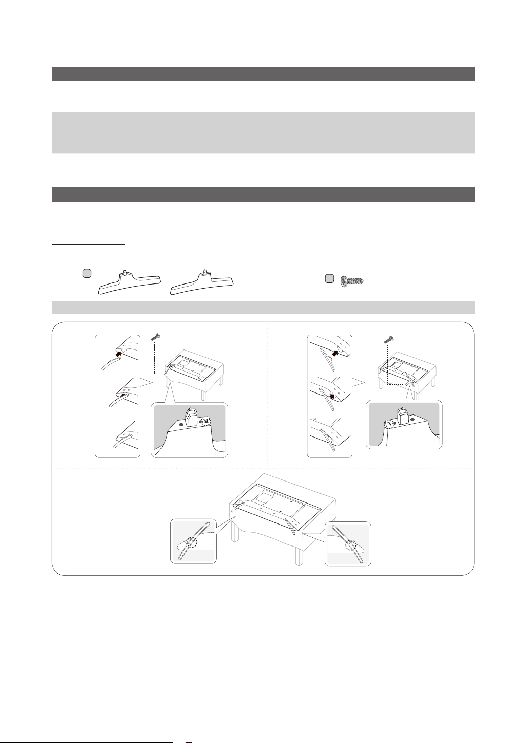
Installing the LED TV Stand
The 32” and larger LED TVs have swivel stands. You can set these stands so that the TVs swivel 20 degrees left and
right or 60 degrees and right or 90 degrees left and right.
Stand Components
When installing the stand, use the provided components and parts.
1
3
A
Stand Screws
(M4 X L12) (2EA)
2
C
M4 X L12 (4EA)
(M4 X L12) (2EA)
✎ Make sure to distinguish between the front and back of the Stand and Stand Guide when assembling them.
✎ Make sure that at least two people lift and move the TV.
English
4
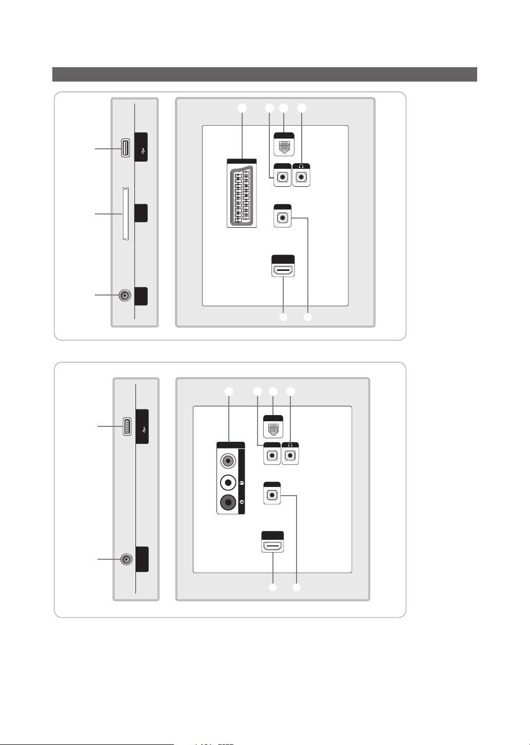
Viewing the Connection Panel
1
2
3
(5V 0.5A) /CLONING
INTERFACE
ANT IN
USB
COMMON
EXT (RGB)
6789
DATA
HP-ID
RJP
HDMI IN
(ARC)
4 5
6780
HG32ED470S
HG32AD470S
1
3
(5V 0.5A) /CLONING
ANT IN
AUDIOVIDEO
DATA
HP-ID
RJP
HDMI IN
(ARC)
USB
AV IN
4 5
English
5

1
2
HG32ED450S
689
(5V 0.5A) /CLONING
USB
EXT (RGB)
COMMON
INTERFACE
HP-ID
RJP
HDMI IN
3
1
3
ANT IN
(5V 0.5A) /CLONING
ANT IN
4 5
HG32AD450S
680
USB
AV IN
HP-ID
AUDIOVIDEO
RJP
HDMI IN
(Except CHINA)
4 5
6
English

✎ Whenever you connect an external device to your TV, make sure that power on the unit is turned off.
✎ When connecting an external device, match the colour of the connection terminal to the cable.
1 USB (5V 0.5A) / CLONING
– Connector for software upgrades and Media Play, etc.
– Service connection.
– USB CLONING support 2.0 Standard only.
2 COMMON INTERFACE
3 ANT IN
– To view television channels correctly, the TV must receive a signal from one of the following sources:
– An outdoor antenna / A cable television system
4 HDMI IN: Connects to the HDMI jack of a device with an HDMI output.
✎ No sound connection is needed for an HDMI-HDMI connection. HDMI connections carry both audio and video.
✎ Use the HDMI IN (DVI) jack for a DVI connection to an external device. Use a DVI to HDMI cable or DVI-HDMI
adapter (DVI to HDMI) for the video connection and the PC/DVI AUDIO IN jacks for audio.
5 RJP: This port is an RJP (Remote Jack Pack) communication port that enables connecting different devices to
additional modules to improve device use and convenience.
6 HEADPHONE JACK: Headphones may be connected to the headphone jack on your TV. While the headphones are
connected, the sound from the built-in speakers is disabled.
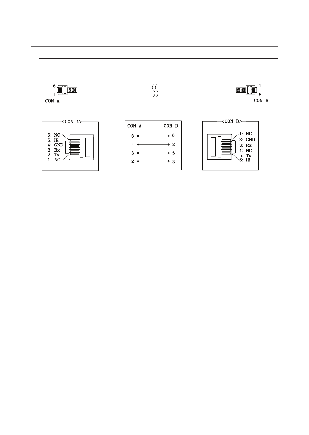
7 D ATA
– Used to support data communication between the TV and the SBB.
– Connects using RJ-12 TV type plugs.
8 HP-ID: Connect the cable to HP-ID and Headphone Jack simultaneously and connect it to separated Headphone
Box. See page 15. When connecting Headphone to Headphone Box, it works same as Headphone function.
9 EXT (RGB)
– In Ext. mode, DTV Out supports MPEG SD Video and Audio only.
0 AV IN
– Connects the Component video / audio.
– Connect the component video cables (optional) to the component jacks ("PR", "PB", "Y") at the back of your TV
and the other ends to the corresponding component video out jacks on the DVD.
– If you wish to connect both the Set-Top Box and the DVD player, you should connect the Set-Top Box to the DVD
Player and connect the DVD Player to the component jacks ("PR", "PB", "Y") on your TV.
– The PR, PB and Y jacks on your component devices (DVD) are sometimes labeled Y, B-Y and R-Y or Y, Cb and
Cr.
– Connect the RCA audio cables (optional) to [R - AUDIO - L] at the back of the TV set and the other ends to the
corresponding audio out jacks on the DVD Player.
English
7
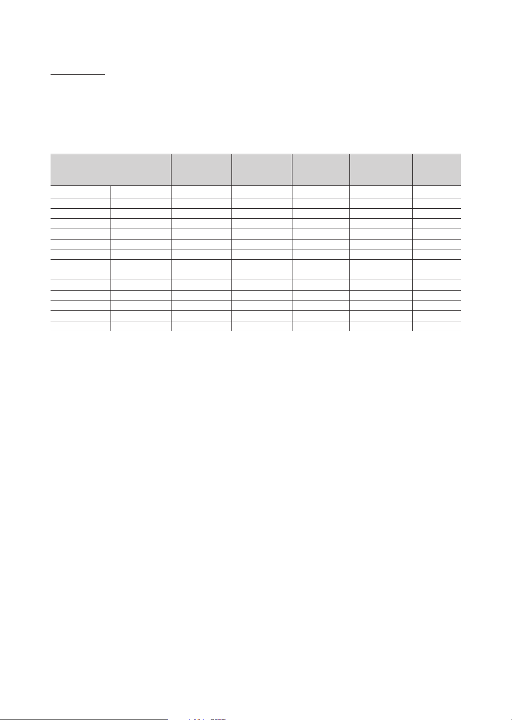
Display Modes
You can also select one of the standard resolutions listed in the Resolution column. The TV will automatically adjust to
the resolution you choose.
After connecting a computer to the TV, set the screen resolution for the TV on the computer. The optimal resolution is
1920 x 1080 @ 60 Hz. If it is set to any other than in the table below, the TV may display nothing. Set the resolution
properly, referring to the user guide of the computer or its graphic card.
The resolutions in the table are recommended.
✎ Optimal resolution is 1366 X 768 @ 60 Hz.
Display Mode Display Format
IBM 720 x 400 70Hz 31.469 70.087 28.322 -/+
VESA DMT 640 x 480 60Hz 31.469 59.940 25.175 -/-
MAC 640 x 480 67Hz 35.000 66.667 30.240 -/-
VESA DMT 640 x 480 72Hz 37.861 72.809 31.500 -/-
VESA DMT 640 x 480 75Hz 37.500 75.000 31.500 -/-
VESA DMT 800 x 600 60Hz 37.879 60.317 40.000 +/+
VESA DMT 800 x 600 72Hz 48.077 72.188 50.000 +/+
VESA DMT 800 x 600 75Hz 46.875 75.000 49.500 +/+
MAC 832 x 624 75Hz 49.726 74.551 57.284 -/-
VESA DMT 1024 x 768 60Hz 48.363 60.004 65.000 -/-
VESA DMT 1024 x 768 70Hz 56.476 70.069 75.000 -/-
VESA DMT 1024 x 768 75Hz 60.023 75.029 78.750 +/+
VESA DMT 1280 x 720 60Hz 45.000 60.000 74.250 +/+
VESA DMT 1366 x 768 60Hz 47.712 59.790 85.500 +/+
Horizontal
Frequency
(kHz)
Vertical
Frequency
(Hz)
Pixel Clock
(MHz)
Sync Polarity
(H/V)
8
English
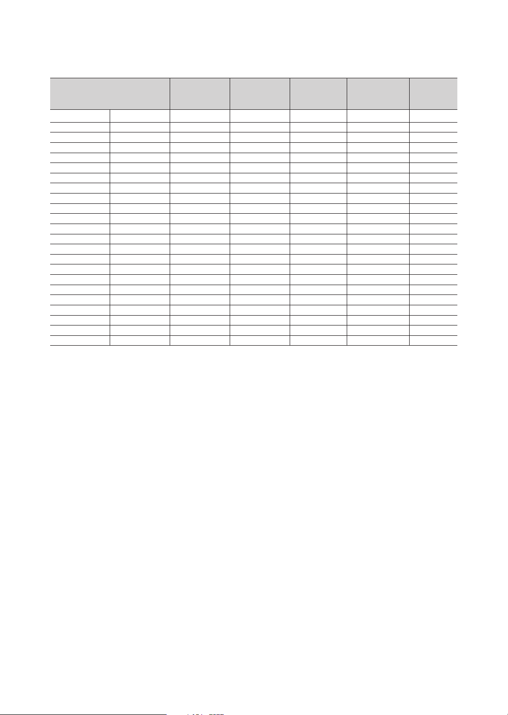
✎ Optimal resolution is 1920 X 1080 @ 60 Hz.
Display Mode Display Format
IBM 720 x 400 70Hz 31.469 70.087 28.322 -/+
VESA DMT 640 x 480 60Hz 31.469 59.940 25.175 -/-
MAC 640 x 480 67Hz 35.000 66.667 30.240 -/-
VESA DMT 640 x 480 72Hz 37.861 72.809 31.500 -/-
VESA DMT 640 x 480 75Hz 37.500 75.000 31.500 -/-
VESA DMT 800 x 600 60Hz 37.879 60.317 40.000 +/+
VESA DMT 800 x 600 72Hz 48.077 72.188 50.000 +/+
VESA DMT 800 x 600 75Hz 46.875 75.000 49.500 +/+
MAC 832 x 624 75Hz 49.726 74.551 57.284 -/-
VESA DMT 1024 x 768 60Hz 48.363 60.004 65.000 -/-
VESA DMT 1024 x 768 70Hz 56.476 70.069 75.000 -/-
VESA DMT 1024 x 768 75Hz 60.023 75.029 78.750 +/+
VESA DMT 1152 x 864 75Hz 67.500 75.000 108.000 +/+
MAC 1152 x 870 75Hz 68.681 75.062 100.000 -/-
VESA DMT 1280 x 720 60Hz 45.000 60.000 74.250 +/+
VESA DMT 1280 x 800 60Hz 49.702 59.810 83.500 -/+
VESA DMT 1280 x 1024 60Hz 63.981 60.020 108.000 +/+
VESA DMT 1280 x 1024 75Hz 79.976 75.025 135.000 +/+
VESA DMT 1366 x 768 60Hz 47.712 59.790 85.500 +/+
VESA DMT 1440 x 900 60Hz 55.935 59.887 106.500 -/+
VESA DMT 1600 x 900RB 60Hz 60.000 60.000 108.000 +/+
VESA DMT 1680 x 1050 60Hz 65.290 59.954 146.250 -/+
VESA DMT 1920 x 1080 60Hz 67.500 60.000 148.500 +/+
Horizontal
Frequency
(kHz)
Vertical
Frequency
(Hz)
Pixel Clock
(MHz)
Sync Polarity
✎ The interlace mode is not supported.
✎ The set might operate abnormally if a non-standard video format is selected.
✎ Separate and Composite modes are supported. SOG is not supported.
(H/V)
English
9
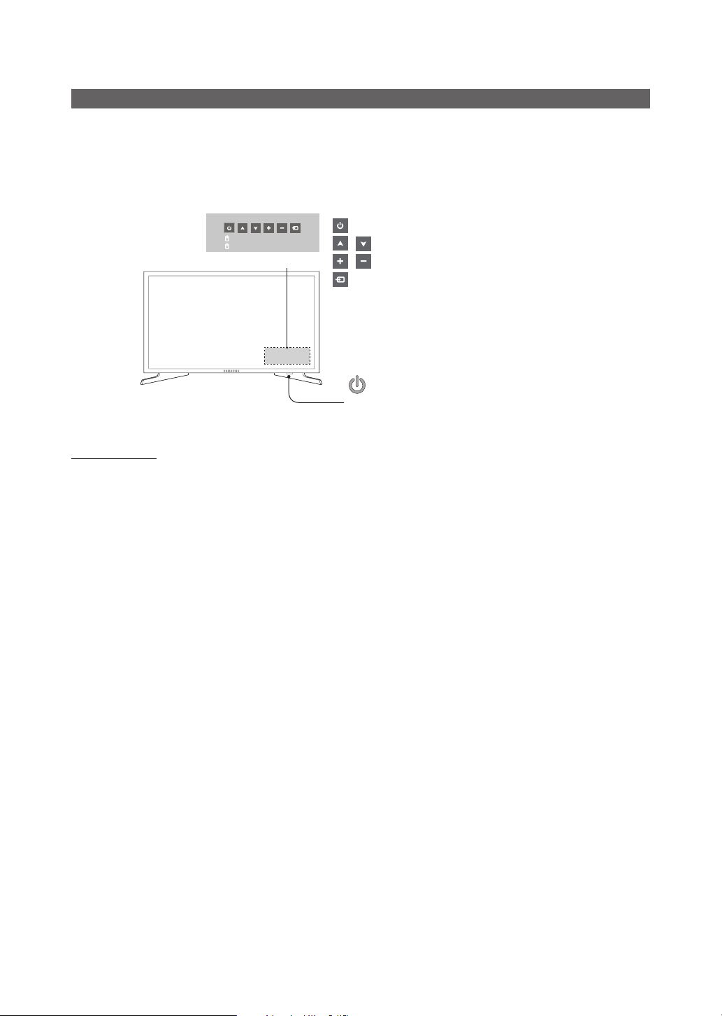
Using the TV's Controller (Panel Key)
Turn on the TV using the P button on the remote control or TV panel.
✎ The TV's Controller at the right bottom of the TV, lets you control the TV without the remote control.
✎ If you press it first, the control menu appears. You can select the function by pressing and holding the TV's controller.
✎ The product colour and shape may vary depending on the model.
✎ With the TV’s Controller, you cannot perform other operations except for turning the TV on or off, changing the channel,
adjusting the volume, and switching the input source.
Press: Move
Press & Hold: Select
Control Menu
: Turns the TV on or off.
/ : Changes channels.
/ : Adjusts the volume.
: Switchs the available video sources.
Remote control sensor/TV Controller
Standby mode
Do not leave your TV in standby mode for long periods of time (when you are away on a holiday, for example). A small
amount of electric power is still consumed even when the power button is turned off. It is best to unplug the power cord.
10
English

Viewing the Remote Control
✎ This remote control has Braille points on the Power, Channel, and Volume buttons and can be used by visually
impaired persons.
Turns the TV on and off.
Have direct access to channels.
Alternately selects Teletext, Double or Mix.
Adjust the volume.
Display channel list on the screen.
Display the main on-screen menu.
Quickly select frequently used functions.
Select on-screen menu items and
change menu values.
Return to the previous menu.
Buttons in the Channel list, Contents
Home menu, etc.
ALARM: Enter the hour you want the TV
to turn on. (HD450S is not supported)
W: Turns the 3D image on or off. ( Not
available )
SUBT.: Displays digital subtitles.
CH LIST
HOME
SUBT.
GUIDE
CONTENT
CLOCK
TTX/MIX
ABCD
ALARM
Display and select available video
sources.
Electronic Programme Guide (EPG)
display.
Cut off the sound temporarily.
Change channels.
Swich to the HOME Screen.
View the Contents Home.
Press to display information on the TV
screen.
CLOCK: When you press INFO key
in standby mode, TV screen displays
the time.
Exit the menu.
Use these buttons in the Contents
Home.
Installing batteries (Battery size: AAA)
Rear of the Remote
✎ After you have intalled the batteries, use a screwdriver to
screw in the screw that holds the battey cover closed.
✎ NOTE
• Use the remote control within 23 feet of the TV.
• Bright light may affect the performance of the remote
control. Avoid using nearby special fluorescent light
or neon signs.
• The colour and shape may vary depending on the
model.
• Remote control button '3D' is not supported.
When pressing these buttons, the TV unit does not
respond.
English
11

¦ Using the Sports Mode
Sports Mode t
✎ MENU m → Applications → Sports Mode → ENTER E
This mode provides optimized condition for watching sports games.
• a (Zoom): Pause playback and divide the picture into 9 parts. Select a part to zoom it in. Press this button again to
resume.
✎ When the Sports Mode is on, the picture and sound modes are set to Stadium automatically.
✎ If you turn the TV off while watching Sports Mode, the Sports Mode will be disable.
✎ When the Data Service is running, the Zoom is not available.
12
English
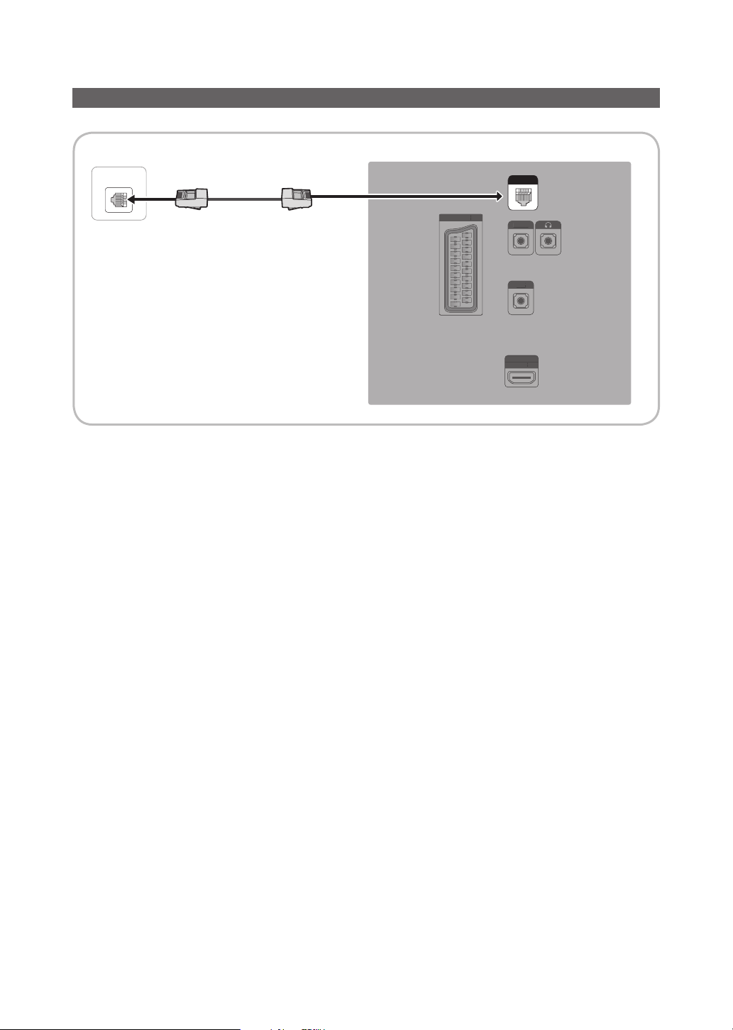
Connecting the TV with SBB (Only for HD470S)
E
)
HP-ID
RJP
H
(
TV Rear Panel
ETH MODEM
Data Cable
EXT (RGB)
XT (RGB
DATA
HP-ID
RJP
HDMI IN
DMI IN
(ARC)
ARC)
1. Connect the DATA jack of the TV to the [ETH MODEM] jack of the STB (SBB) with the Data cable.
✎ Use data communication.
English
13
¦ List of Vendors and Compatible Data Cables Supplied with the TV
• Confirm that you are using the correct data cable for your vendor. Refer to the code label on the data cables.
14
English

¦ HP-ID
HP-ID
A
HP-ID
An additional Headphone Box can be installed on a bed or business desk for added convenience. The installation
procedures are given below.
• Detailed Drawing of the Headphone Box.
TV Rear Panel
HEADPHON BOX
HP-ID
TV HP-ID jack
Shield wire
Red Wire (Audio-R)
Red wire + White wire
Headphone Box
TV Headphones jack
Whitewire (Audio-L)
Shield Wire
<Headphone Box>
English
15

Connecting the MediaHub HD (Only for HD470S)
(
)
US
O
O
I
C
ANT
IN
DATA
E
)
D
Output to any external source connected to MediaHub HD on the hotel desk.
MediaHub HD Rear
USBRS/232
HDMI
1
RS-232 Data Cable
HDMI cable
2
(5V 0.5A) /CLONING
5V 0.5A
USB
B
/CLONING
EXT (RGB)
XT (RGB
COMMON
INTERFACE
C
NTERFA
MM
N
E
ANT IN
TV Rear Panel
DATA
HP-ID
HP-I
RJP
HDMI IN
(ARC)
1. Connect the RJP port of the TV and the RS/232 port of the MediaHub HD.
2. Connect the HDMI IN port of the TV and the HDMI port of the MediaHub HD.
• MediaHub HD
– The MediaHub HD is a hardware module that has different Audio Video inputs (A/V, Audio, PC, HDMI and USB)
and corresponding outputs. The corresponding output sources connect from MediaHub to the TV. MediaHub
communicates with the TV via RS232. Hot Plug & Play is a function that allows hotel guests to connect an
external source to the MediaHub. MediaHub communicates with the TV by sending messages regarding Active/
Inactive sources. The TV switches to the Active external source.
– You have to connect the HDMI of the MediaHub to the HDMI IN port of the TV.
– When the TV is on, connect the TV and the RJP within 10 seconds.
• Special features
– PIP
– Auto Detection
English
16
 Loading...