


PROJECTION TV RECEIVER
Chassis : P58A(N)
Model : HCN559WX/XAA HCN5529WX/XAA
HCN529WX/XAA
PROJECTION TV RECEIVER CONTENTS
Specifications
Alignment and Adjustments
Exploded View and Parts List
Electric Parts List
PCB Diagrams
Schematic Diagrams
1.
2.
3.
4.
5.
6.

ELECTRONICS
© Samsung Electronics Co., Ltd. APR. 2003
Printed in Korea
AA82-00489A

Specifications
Samsung Electronics 1-1
1. Specifications
Broadcasting System
Scanning System
Tuning Range
Antenna Impedance
Intermediate Frequency
Sound Output
Rated Voltage
W/B Coordinates
High Voltage
FUSE
Power Consumption
Dimension
Weight
NTSC
Progressive Scanning
VHF : CH2 ~ CH13
75 ohm Unbalanced
Video : 45.75 MHz
Sound : 42.25 MHz
Chrominance Subcarrier : 42.17 MHz
STD : 10W
MAX : 15W
120V / 60 Hz
Hx : 275 Hy : 280 Y : 6.5
Lx : 285 Ly : 290 Y : 0.28
29KV
250V/6.3A
CODE NO : 3601-000300
240W
HCN479W: 1132 x 624 x 1325 mm ; 44.6 x 24.5 x 52.1 inch
HCN529W: 1230 x 530 x 1393 mm ; 48.4 x 20.8 x 54.8 inch
HCN559W: 1312 x 651 x 1435 mm ; 51.6 x 225.6 x 56.5 inch
HCN5529W: 1312 x 695 x 1441 mm ; 51.6 x 27.3 x 56.7 inch
HCN659W: 1529 x736 x 1587 mm ; 60.0 x 28.9 x 62.4 inch
HCN479W: 76 Kg; 167 lbs
HCN529W: 73.5 Kg; 167 lbs
HCN559W: 99.5 Kg; 219 lbs
HCN5529W: 87.8 Kg; 192 lbs
HCN659W:136 Kg; 299 lbs

MEMO
1-2 Samsung Electronics
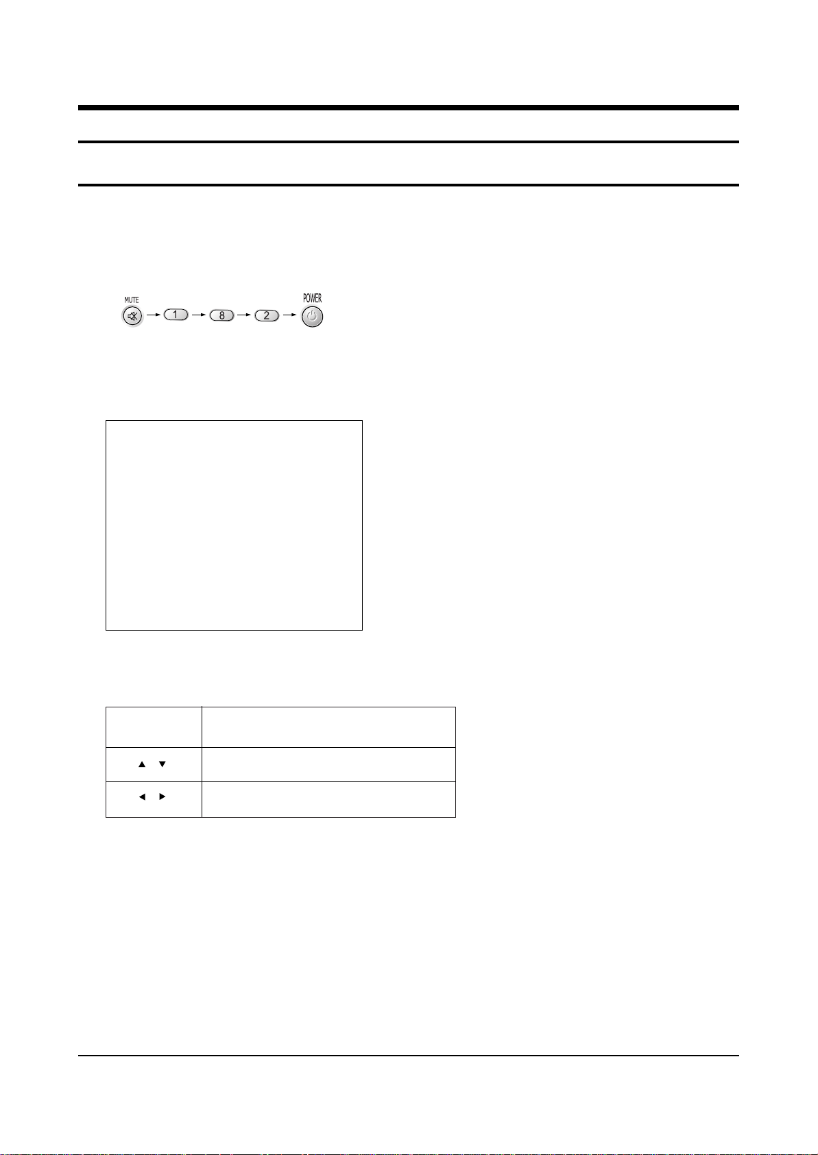
MAIN MENU MENU DISPLAY
Select item by moving cursor
Decrease or increase the adjustment values
Alignment and Adjustments
Samsung Electronics 2-1
2. Alignment and Adjustments
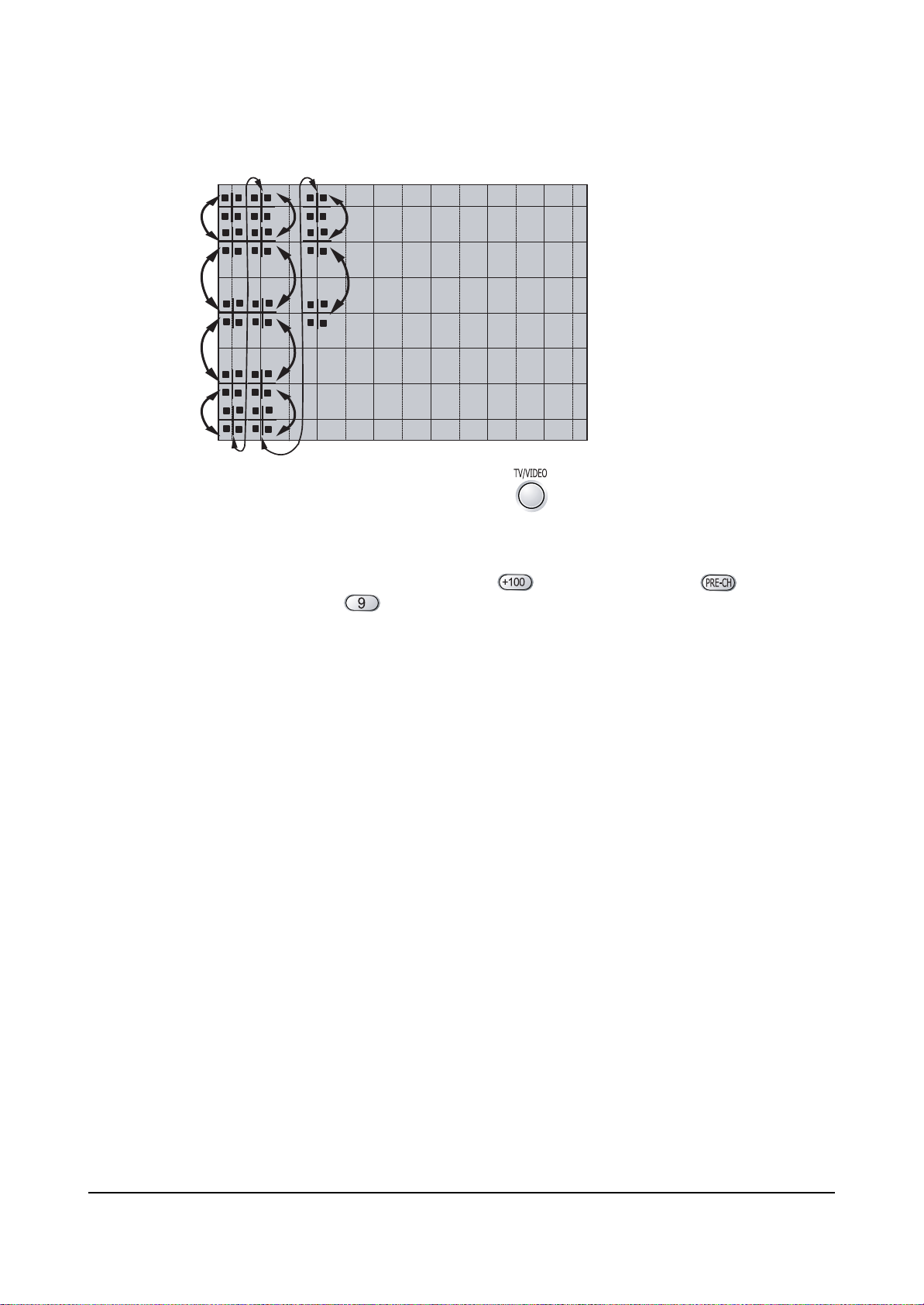
2-1 When entering the service mode:
1. Turn on the TV, and then select “STANDARD”on the picture adjustment mode.
2. Turn off the TV (STAND-BY).
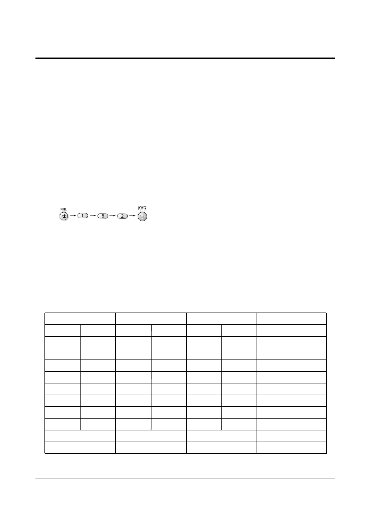
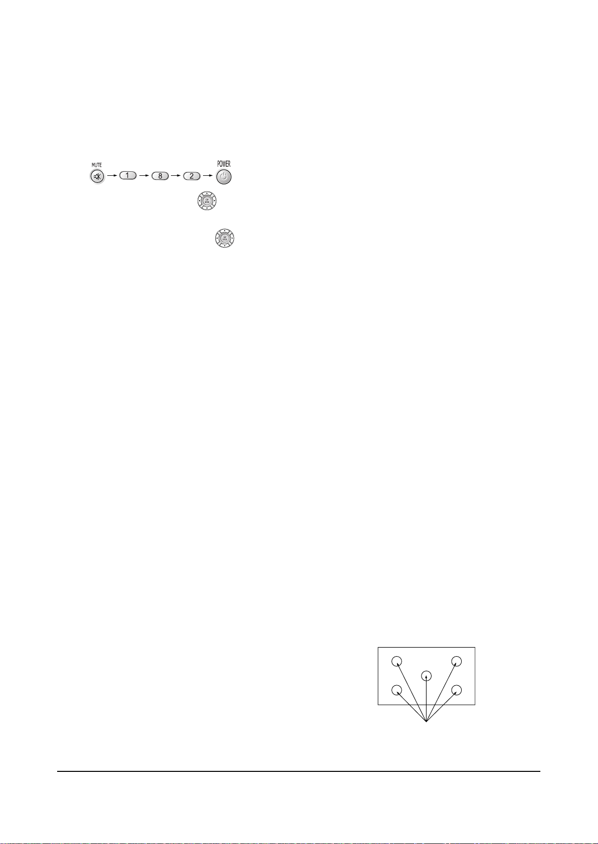
3. Enter the service mode by pressing the remote control keys in the following sequence :
Note : If necessary, re-do steps 1~3.
Initial display when the service mode is switched.
DEFLECTION
VIDEO ADJUST 1
VIDEO ADJUST 2
VIDEO ADJUST 3
VIDEO ADJUST 4
VIDEO ADJUST 5
VIDEO ADJUST 6
VERSION INFORMATION
RESET
4. Service Mode Control Keys
/
/
Alignment and Adjustments
2-2 Samsung Electronics
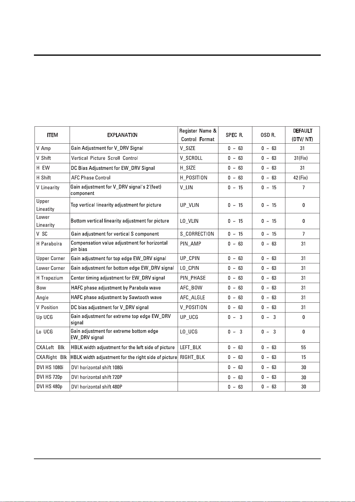
2-2-1 Defection
2-2 Factory Data
☞ DVI connection item is corresponded to DVI application model.
(HCN559W/HCN5529W)
Alignment and Adjustments
Samsung Electronics 2-3
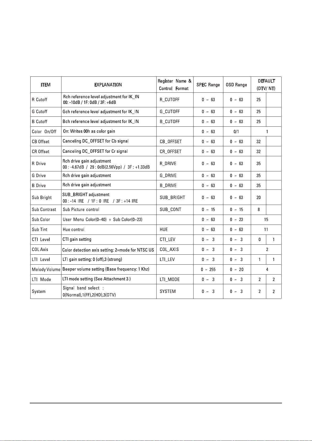
2-2-2 Video Adjust 1
Alignment and Adjustments
2-4 Samsung Electronics
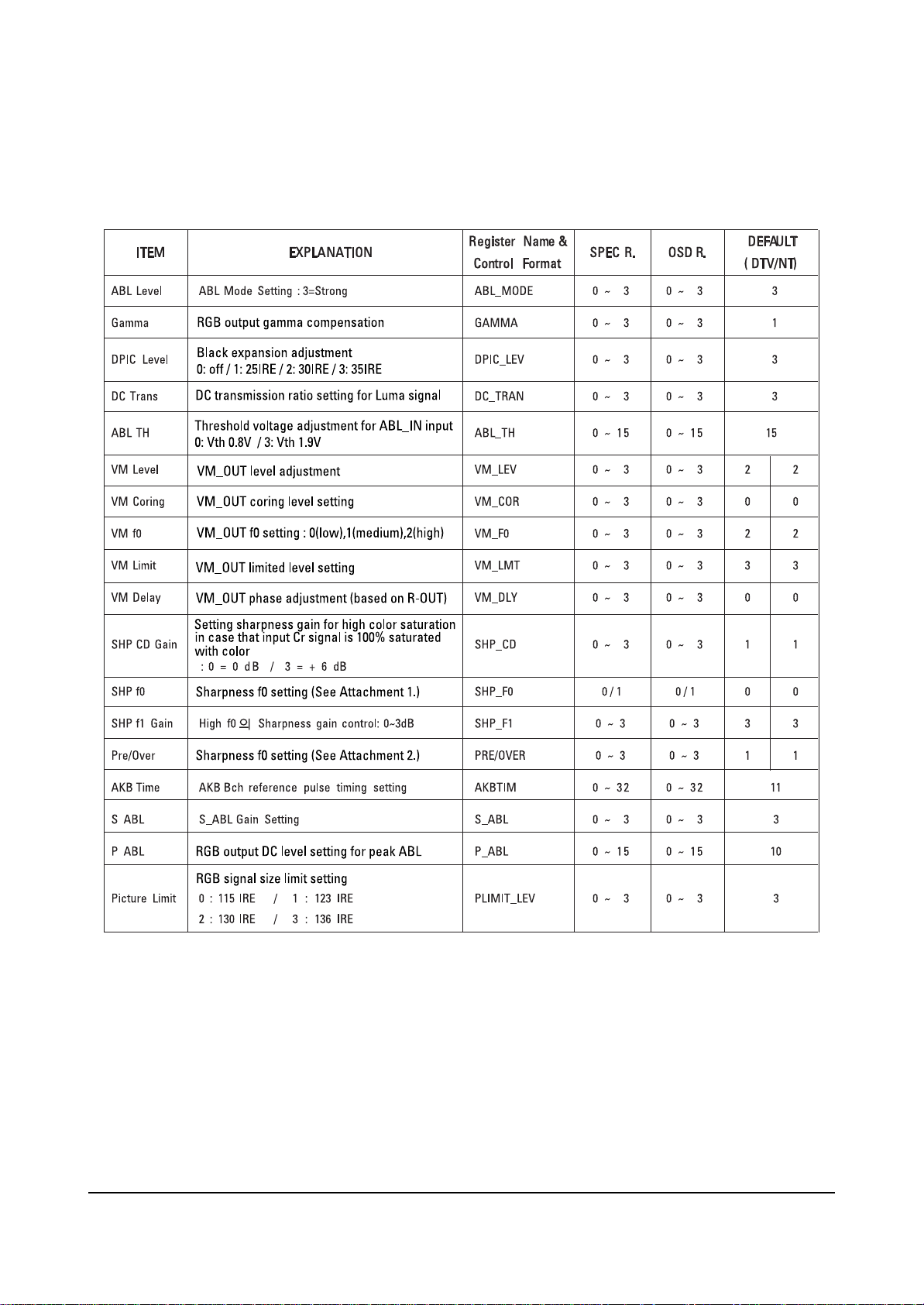
2-2-3 Video Adjust 2
Alignment and Adjustments
Samsung Electronics 2-5
2-2-4 Video Adjust 3
Alignment and Adjustments
2-6 Samsung Electronics
2-2-5 Video Adjust 4
Alignment and Adjustments
Samsung Electronics 2-7
2-2-6 Video Adjust 5

Alignment and Adjustments
2-8 Samsung Electronics
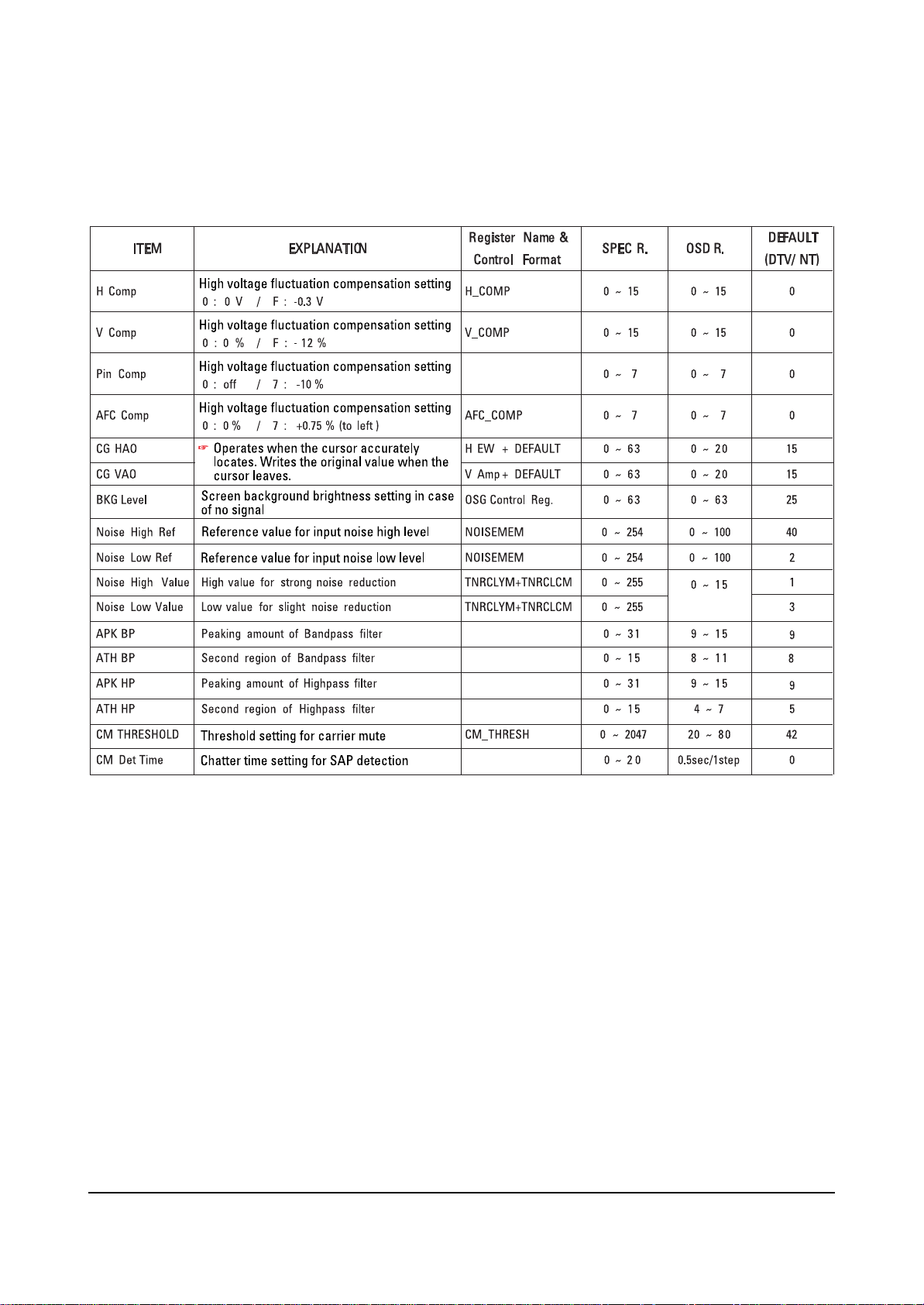
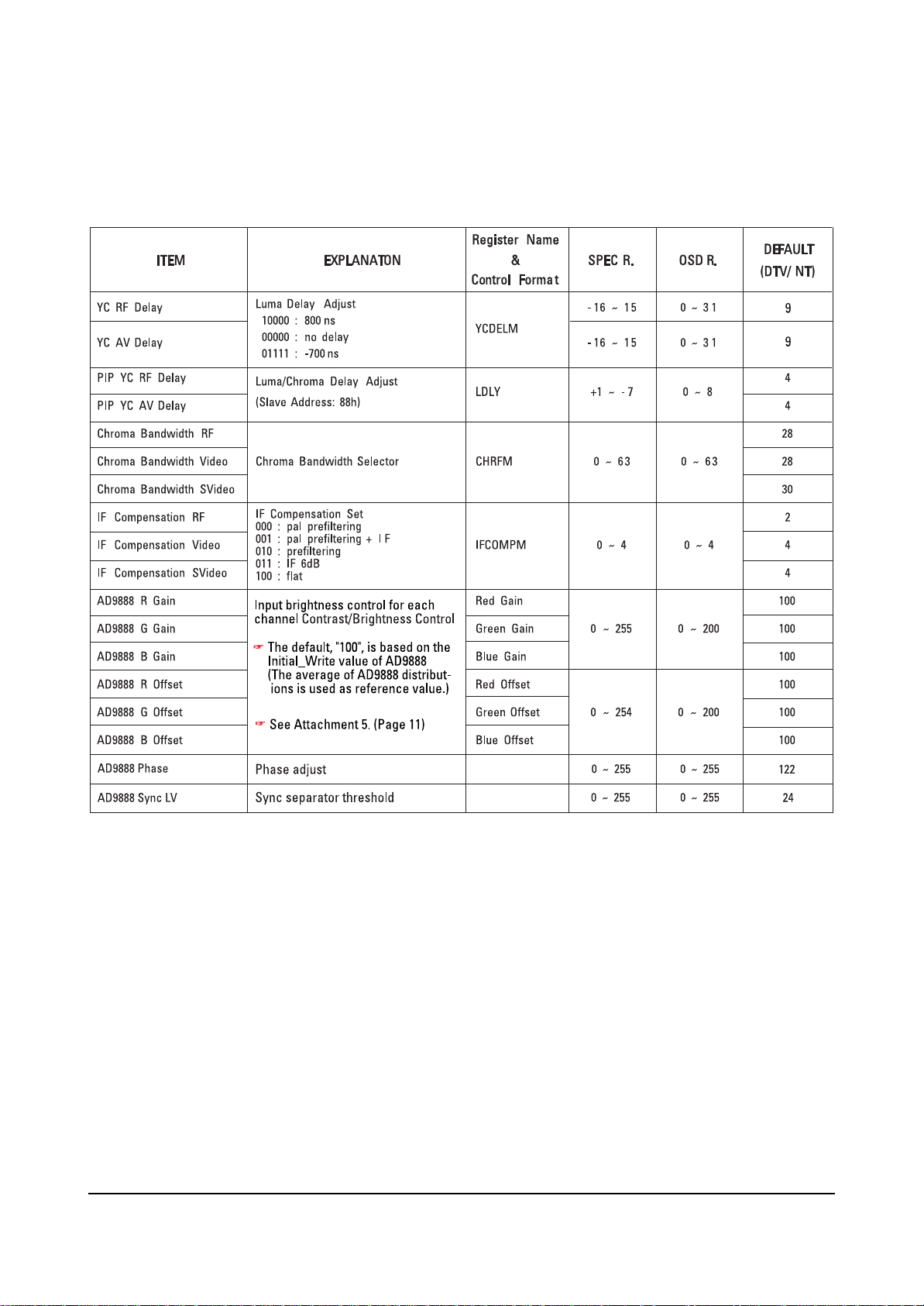
2-2-7 Video Adjust 6
ITEM EXPLANATION ITEM 1 CONTROL REG. SPEC R. OSD R.
NR SCALEMAX Y
NR SCALEMAX C
NR SCALEMIN Y
NR SCALEMIN C
NR HPF TH
NR EDGE TH
NR SEL NR Mode Select
CE UPPER CE Upper Boundary
CE CUTOFF CE Lower Boundary
CE GAIN L
CE GAIN U
DEC_GAIN L
DEC_GAIN U
DE GAIN
DE NOISEDET GAIN
DE CORING DE Coring Value
DE H CONT DE Horizental Shoot Reduce
DE V CONT DE Vertical Shoot Reduce
BS GAIN Black Stretch Gain
WS GAIN White Stretch Gain
CTE GAIN CTE Gain
WTE GAIN WTE Gain
SUB BRIGH TR
SUB BRIGHT G
SUB BRIGHT B
SUB CONTRAST R
SUB CONTRAST G
SUB CONTRAST B
Temporal
Spatial NR Gain
CE
DEC
DE Gain
Bright
Contrast Control
NR Gain
Gain
Gain
Control
0x 293 [15:8]
0x2 93[7:0]
0x 294 [15:8]
0x2 94[7:0]
0x2 98[6:4]
0x2 98[2:0]
0x29 F[13:12]
0x2 B0[7:0]
0x 2B0[15 :8]
0x 2B3[15 :8]
0x2 B3[ 7:0]
0x 2D5[15:8]
0x2 D5[ 7:0]
0x3 17[6:0]
0x3 16[3:0]
0x3 11[5:0]
0x3 1C[9:0]
0x3 1D[ 9:0]
0x 331 [15:5]
0x 332 [15:5]
0x3 52[8:0]
0x3 45[9:0]
0 x364[7 :0]
0 x365[7 :0]
0 x366[7 :0]
0 x361[7 :0]
0 x362[7 :0]
0 x363[7 :0]
0 ~ 255 0 ~ 255 48 32
0 ~ 255 0 ~ 255 48 32
0 ~ 255 0 ~ 255 16 16
0 ~ 255 0 ~ 255 16 16
0~7 0~7 0 0
0~7 0~7 5 4
0~3 0~3 2 3
0 ~ 255 0 ~ 255 240 220
0 ~ 255 0 ~ 255 32 32
0 ~ 255 0 ~ 255 75 64
0 ~ 255 0 ~ 255 75 64
0 ~ 255 0 ~ 255 96 75
0 ~ 255 0 ~ 255 96 75
0 ~ 127 0 ~ 127 80 64
0~15 0~15 10 8
0~63 0~63 0 0
0 ~ 1023 0 ~255 128 8
0 ~ 1023 0 ~255 128 32
0 ~ 2047 367 ~ 397 375 375
0 ~ 2047 367 ~ 397 375 375
0 ~ 511 0 ~ 255 176 176
0 ~ 1023 250 ~ 350 300 300
-128 ~ 127 0 ~ 255 128 128
-128 ~ 127 0 ~ 255 128 128
-128 ~ 127 0 ~ 255 128 128
0 ~ 255 0 ~ 255 128 128
0 ~ 255 0 ~ 255 128 128
0 ~ 255 0 ~ 255 128 128
DEFAULT
(DTV/ NT)
Alignment and Adjustments
Samsung Electronics 2-9
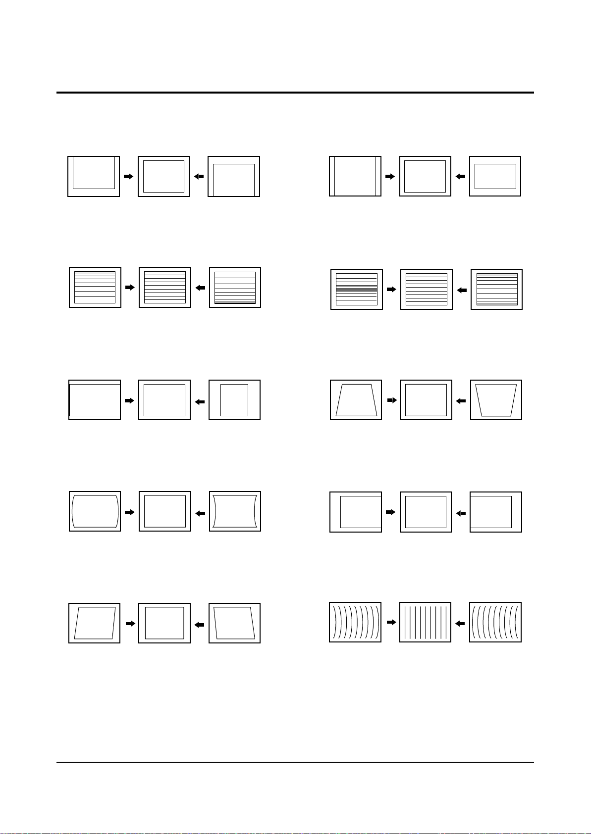
2-3 Screen Change (When adjusting I2C Bus Geometric items)
1 V SHIFT
2 V LINEARITY
3 H SIZE
6 V SIZE
7 V - S - CORRECTION
8
PIN PHASE
4
PIN AMP
5 V ANGLE
9 H SHIFT
10 V BOW
Alignment and Adjustments
2-10 Samsung Electronics
2-4 Other Adjustments
2-4-1 Screen Adjustment
1. Warm up the TV for at least 30 minutes.
3. Turn to the Video Mode (No Signal) using a
remote-control.
5. Adjust the VR (VR501, VR531, VR561) screen
so that RK, GK, BK pulse is 20Vp-p each.
(Turn the R,G,B VR screen fully
counterclockwise in the area of each flyback
line.)
2-4-2 White Balance Adjustment
1. Select the “STANDARD” video mode.
3. In the stand-by mode, press the remote-control
keys in the following sequence:
2. Select the “STANDARD” video mode.
4. Connect an oscilloscope to RK,GK,BK.
2. Input 100% white pattern.
4. Warm up the TV for at least 30 minutes.
5. W/B Adjustment Instruction
! RF-NT ; Set to ‘Color-off’. Then read the coordinates. (Target-A)
@ RF-NT ; Adjust high light brightness and low light white balance for AD9888.
Set to ‘color-on’. (Target-A) → CH1
# RF-NT ; Set to ‘color-off’. Then adjust CXA2165. (Adjustment coordinates : specified spec) → CH2
$ DVI(DTV)-Mode conversion ; Set to ‘color-off’.
Then adjust CXA2165. (Adjustment cordinates ; specified spec) → CH3
% DVI(DTV)-Mode conversion ; Set to ‘Color-on’.
Then adjust CR/CB for CXA2165. (Adjustment coordinates : low light coordinate spec) → CH4
6. Adjustment Sequence
CH-1 ; RF
Color
R-offs
G-offs
B-offs
R-Gain
G-Gain
B-Gain
On
0
0 L/L(Y)
0
255(Fix)
0 H/L(Y)
255(Fix)
AD9888 Offset adjustment
Target ; initial value
CH-2 ; RF
Color
R-C
G-C
B-C
R-D
G-D
B-D
SCT
SBT
Off
0
Fix
0
0
Fix
0
0
0
CXA2165 adjustment
Target ; selected spec
CH-3 ; DVI(DTV)
Color
R-C
G-C
B-C
R-D
G-D
B-D
SCT
SBT
Off
0
Fix
0
0
Fix
0
0
0
CXA2165 adjustment
Target ; selected spec
CH-4 ; DVI(DTV)
Color
CR
CB
On
0
0
CXA2165 CR,CB adjustment
Target ; selected spec (L/L)
7. Press the Menu key to exit.
Alignment and Adjustments
Samsung Electronics 2-11
2-4-3 Sub-Brightness Adjustment
1. Input a sub-brightness adjustment signal.
(TOSHIBA PATTERN)
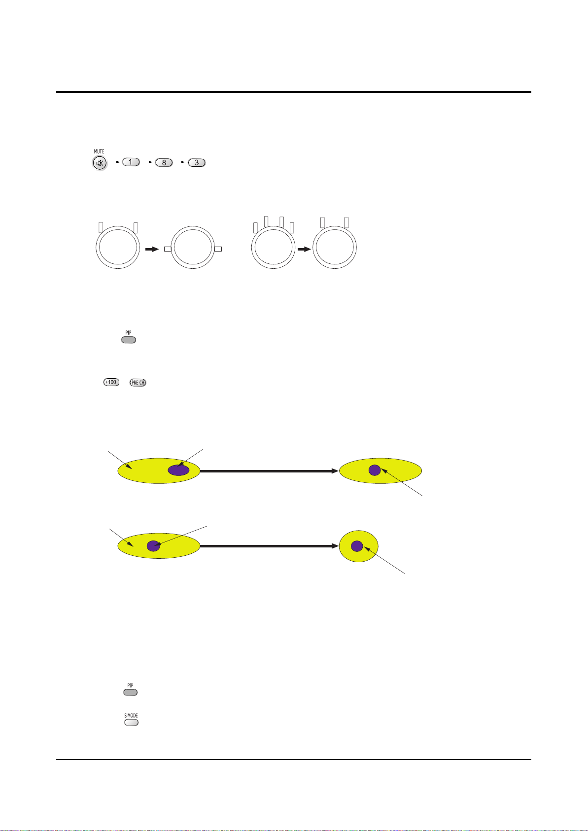
2. In the stand-by mode, press the remote-control
keys in the following sequence :
3. Select SBT by pressing the keys.
4. Adjust so that the 63 step on the right side of
the screen is not seen (Use the keys).
5. Press the Menu key to exit.
2-4-4 High Voltage (29KV) Check
PRECAUTION
1. Input a lion head pattern.
2. Select “STANDARD” video mode.
3. Warm up the TV for at least 10 minutes.
4. Use a 1000:1 probe.
ADJUSTMENT
1. Connect the (+) terminal of the 1000:1 probe to
the high voltage distributor and the (-)
terminal to GND (located on the deflection
board).
2. Adjust RR471S (located on the deflection
board) so that the digital meter indicates
DC 29V ± 0.1V.
2-4-5 F.S. (Fail Safe) Adjustment
Note : The finished product has VR (RR402S)
adjusted and glued at the factory.
If necessary, do the F.S. adjustments in the
following sequence.
1. Use a digital multimeter.
2. Connect the digital multimeter to the JIG pin
(DZ482S) terminals
3. Adjust VR (RR402S) so that the voltage
becomes 2.25V.
4. After the adjustments are complete, be sure to
glue VR (RR402S) correctly.
2-4-6 F.S. (Fail Safe) Circuit Check
Note : The F.S. Circuit check must be performed
after servicing.
1. Turn on the TV.
2. Select the “STANDARD” video mode.
3. Short F/S Test point (located on the SUB PCB).
Then, both sound and picture disappear.
(Note: Even if the shorted terminals are
removed, both sound and
picture do not appear. This proves the F.S.
circuit is working. )
4. To restore both sound and picture, turn off the
TV and reset it after about 30 seconds.
2-4-7 Static Focus Adjustment
PRECAUTION
1. Select the “STANDARD” video mode.
2. Input a crosshatch pattern.
3. Cover the lenses that are not being adjusted.
4. Connect a convergence jig and read data.
5. Adjust the lens for best focus.
(See Fig, 2-1)
STATIC FOCUS (CONTINUED)
Vary the focus pack VR (Red, Blue) on the
front cabinet. Adjust the TV for best possible
focus around the center of the crosshatch
pattern, without losing overall screen balance.
Figure Crosshatch Pattern
Examine these points together.
Fig. 2-1 Crosshatch Pattern.
Examine these points together
Alignment and Adjustments
2-12 Samsung Electronics
2-4-8 Lens Focus Adjustment
PRECAUTIONS
1. Do this adjustment after the static focus
adjustment and the tilt adjustment.
2. Select the “STANDARD” video mode.
(Contrast:100, Brightness:50)
3. Input a crosshatch pattern.
ADJUSTMENT
1. Loosen the lens screws.
2. Cover the two lenses that are not being
adjusted.
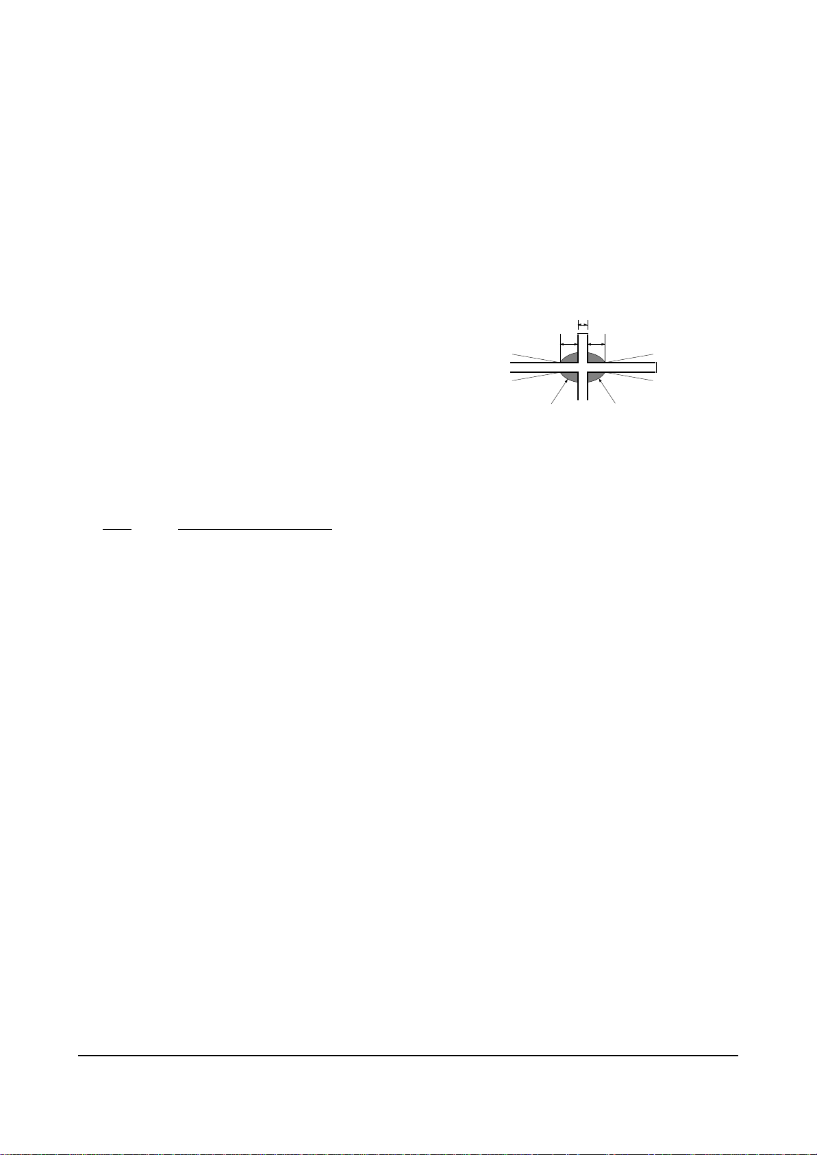
3. Adjust the lens, observing the color aberration
vertically and horizontally within 3 blocks of
the center of the crosshatch pattern.
4. When the lens is turned clockwise, the color
aberration will change as follows:
Lens Color Aberration Change
R Orange - Crimson
G Blue - Red
B Purple - Green
5. Green lens adjustment:
Set the lens at the point where Blue just
changes to Red. If the color aberration is
irregular throughout the picture screen, adjust
the lens to show Red color aberration
(approximately 1~3 mm area) within a 3-block
grid around the horizontal center-line. If the
color aberration is irregular, adjust the lens as
shown in the diagram below. (Accurate
alignment of Green is important for overall
color quality.)
6. Red lens adjustment
Set the Red lens at the point where Orange
becomes Crimson.
7. Blue lens adjustment
Set the Blue lens at the point where Purple
becomes Green.
P
L1
L2
RED ABERRATION
BLUE ABERRATION
L1, L2 < P
_
Fig. 2-2 Color Aberration
Alignment and Adjustments
Samsung Electronics 2-13
1. Select the “STANDARD” video mode.
2. Warm up the set at least for 10 minutes.
3. Enter the Convergence mode by pressing the remote control buttons in the following sequence
:
4. Set the Beam Alignment Adjustment CY to Zero magnetic field area.
5 Press the button on the remote control, and a vibrating dot-pattern appears.
6. Adjust the Focus-pack VR for defocusing.
7. Mute the other patterns (R/B) other than G-PATTERN.
(Use / buttons on the remote control.)
8. Adjust the 2, 4 polarities of VM-COIL as shown in figure below.
9. Adjust the G-Focus until any light around the core disappears.
10. Adjust G-Focus so that the surrounding flash can disappear from the spot.
11. After G-Focus adjustments are complete, adjust R-Focus as above procedures.
12. The B-CRT adjustments can be omitted because the variance of beam focus is small.
(Only Vm-coil is mounted.)
13. Adjust the Focus-pack VR for fine focusing.
14. Press the button on the remote control, and the mode changes to the Convergence Adjustment
mode.
15. Press the button on the remote control to return to normal viewing.
2-5 Beam alignment Adjustments
(Creation of CPM Zero Magnet)
(Creation of the 2-pole/4-pole zero magnets)
G-FOCUS
(Varying G-Focus Pack)
G-FOCUS
(When VM 2-Pole Adjustment is completed)
CORE
CORE
Varying the 2-pole of VM
Varying the 4-pole of VM
(Positioning the Core in the Center)
(Adjust until the light around
the core becomes a circle)
Alignment and Adjustments
2-14 Samsung Electronics
2-6 Convergence-Jig
2-6-1 HCN479W
2-6-2 HCN559W/5529W
X 1045, Y 588 (X:396=12*2+ 31*12, Y:48 8=40*2+68*6)
48.20mm
81.93mm
48.20mm
31.67mm 81.81mm
31.67mm
X 1225, Y 686 (X:396=12*2+ 31*12, Y:48 8=40*2+68*6)
37.12mm 95.90mm
56.23mm
95.59mm
56.23mm
37.12mm
Alignment and Adjustments
Samsung Electronics 2-15
2-6-3 HCN659W
2-6-4 HCN529W
X 1442, Y 8 38 (X:396 =1 2*2+31 *12, Y: 488=40*2+68*6)
68.69mm
116 .77mm
68.69mm
43.70mm 112 .88mm
43.70mm
X 1153, Y 649 (X:396=12*2+ 31*12, Y:48 8=40*2+68*6)
53.20mm
90.43mm
53.20mm
34.94mm 90.26mm
34.94mm
Alignment and Adjustments
2-16 Samsung Electronics
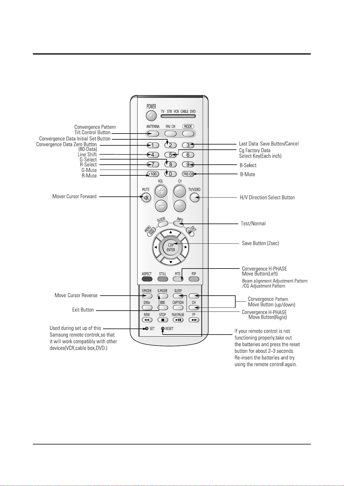
2-7 Remote Control Key Functions in Convergence Mode
Alignment and Adjustments
Samsung Electronics 2-17
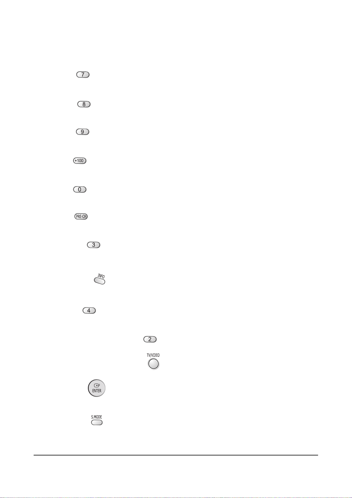
2-7-1 KEY Function
1. R-SELECT
Press to select RED color.
2. G-SELECT
Press to select GREEN color.
3. B-SELECT
Press to select BLUE color.
4. R-MUTE
Press to mute RED color.
5. G-MUTE
Press to mute GREEN color.
6. B-MUTE
Press to mute BLUE color.
7. CANCEL KEY
Press to revert to the previous data during the Convergence
Adjustment.
8. TEST/NORMAL
Press to check TV mode in the Convergence Mode.
9. LINE SHIFT
Press to move a line up/down or left/right.
10. FACTORY DATA SELECT BUTTON
Press to call the factory default values.
11. H/V DIRECTION SELECT BUTTON
Press to switch the cursor direction horizontally or vertically.
12. SAVE BUTTON
After the Convergence Adjustments are completed, press to save data.
13 EXIT BUTTON
After the Convergence adjustments are completed, press to exit to TV mode.
Alignment and Adjustments
2-18 Samsung Electronics
14. MOVE CURSOR FORWARD
Press to move the cursor right or down.
15. MOVE CURSOR REVERSE
Press to move the cursor left or up.
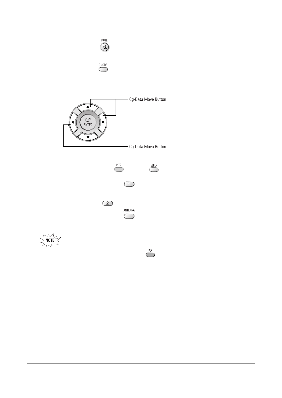
16. CONVERGENCE PICTURE MOVE BUTTON
17. CONVERGENCE MOVE BUTTON
Press to move the convergence left ( ) or right ( ) .
18. CONVERGENCE DATA ZERO BUTTON
Press to zero the convergence correction data.
19. INITIAL DATA SET BUTTON
20. Convergence Pattern Tilt Control Button
After pressing the ANTENNAbutton, use the Channel Up/Down and Volume +/- buttons to create
a tilt to the Convergence Pattern.
Note : Use the following two buttons only when they are indispensable.
21. Beam aligment Adjustment Pattern achieve Button
Alignment and Adjustments
Samsung Electronics 2-19
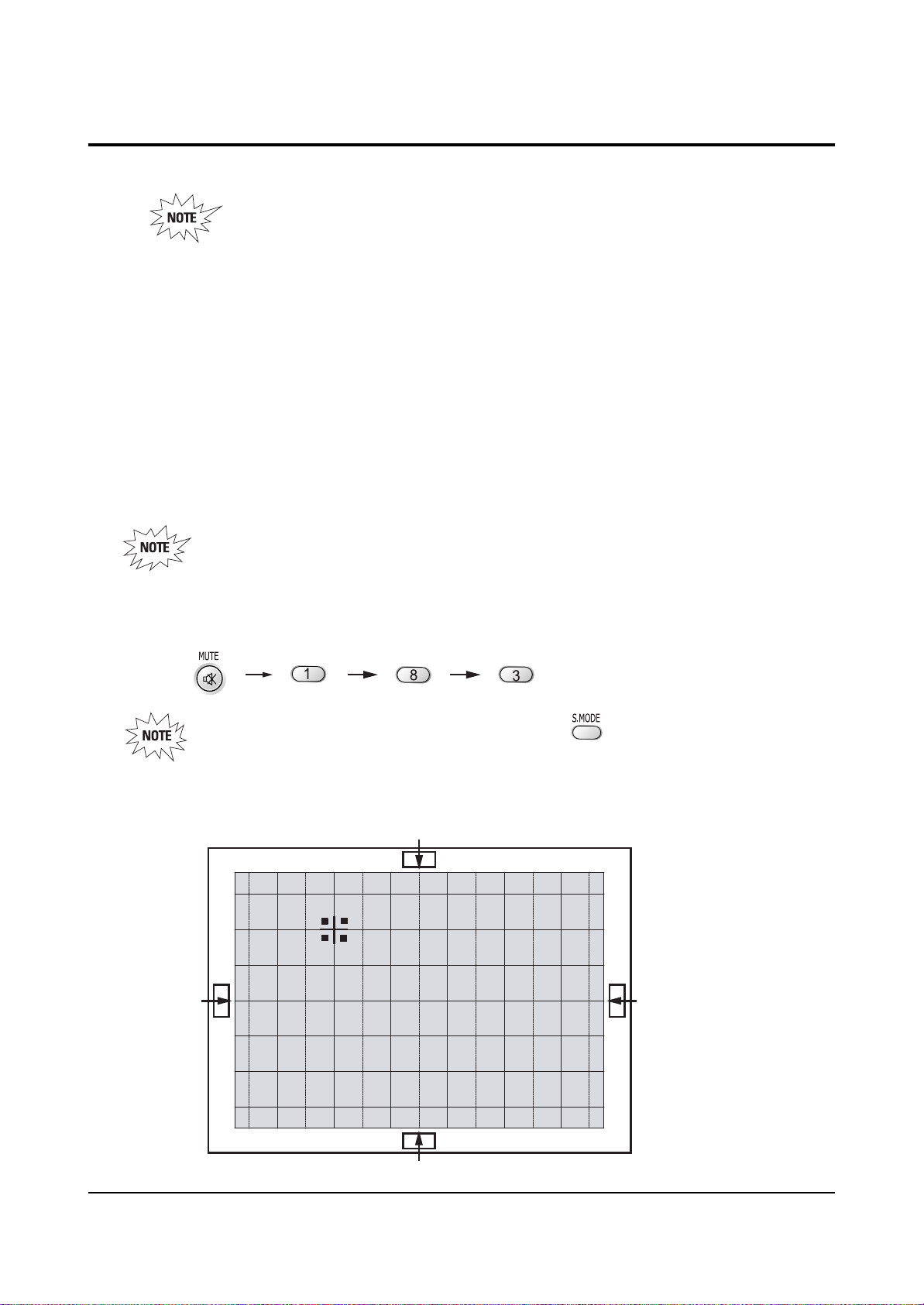
2-8 Convergence Adjustment
Special Notes
✏ A sensor is attached on the center of each side of the Convergence Mode pattern
(see figure below). The sensors are required for normal Perfect Focus function.
✏ Use a screen jig to do the convergence adjustments correctly (Especially, perform
correct convergence adjustments on the center of each side where a sensor is located.)
✏ Do the convergence adjustments correctly. Otherwise, any Perfect Focus error can
happen.
1. Warm up the TV for a least 30 minutes.
2. Input an NTSC Signal.(Use an antenna or AV source.)
Make sure that deflection yoke are properly adjusted so that the center of
Green, Red, Blue pattern is aligned on the center of screen jig.
3. Enter the Convergence Mode by Pressing the remote control keys in the following sequence:
If OSD displayed as shown in figure below, press the key to exit.
Then, redo step 3 to enter the Convergence Mode.
After entering the Convergence Mode, Stand by for about five seconds
before doing the adjustments.
2-8-1 Convergence Adjustment)
Alignment and Adjustments
2-20 Samsung Electronics
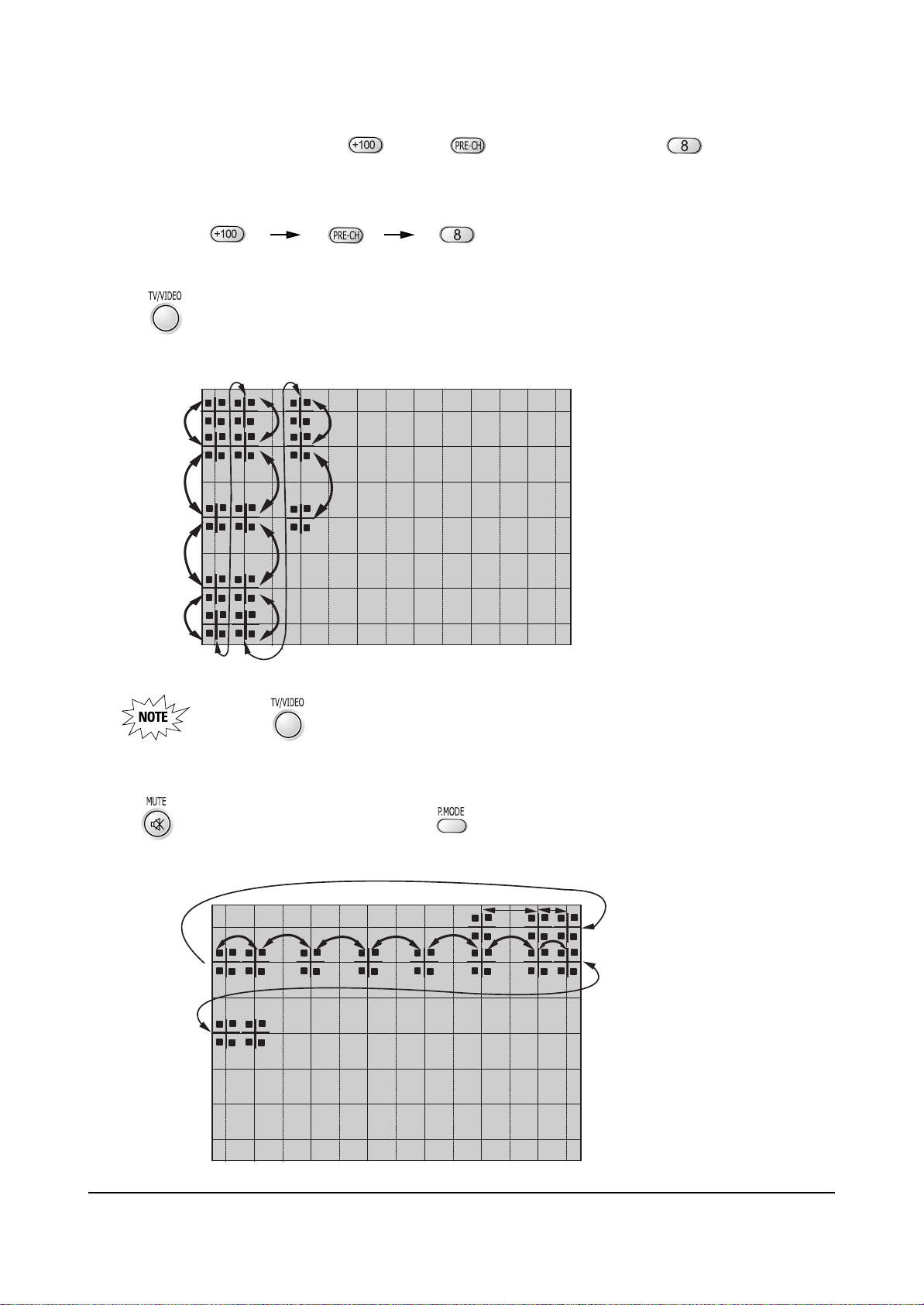
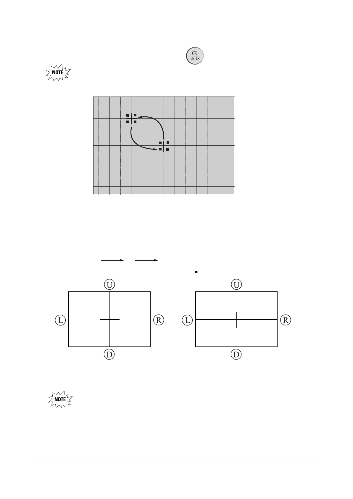
4. To adjust GREEN, first press the and the keys, and then press the key.
Press to move the cursor right or down.
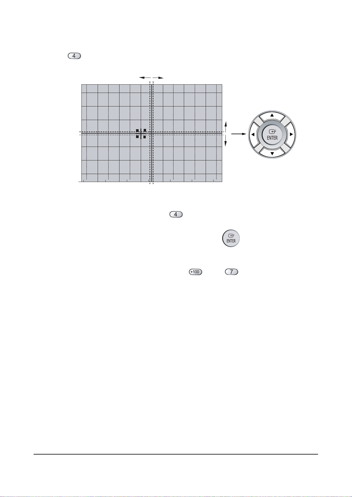
5. The key moves the cursor horizontally or vertically.
When the key is pressed once again, the cursor moves horizontally.
6. . The key moves the cursor right, and the key moves the cursor left.
Alignment and Adjustments
Samsung Electronics 2-21
7. Use the key for overall balance.
8. After the Line Shift is cancelled by pressing the key, use the Channel and Volume keys
(Up/Down)to make big adjustments.
9. After the green convergence adjustments are completed, press the key to save the data.
10. Superimpose the Red and Green colors by pessing the and the keys.
Alignment and Adjustments
2-22 Samsung Electronics
11. To adjust RED, redo steps 5~7.
When the cursor moves vertically
12. To superimpose the blue and green colors, press (1) the key for R-Mute, (2) the key
to cancel the B-Mute, and (3) the key for B- select
13. To adjust BLUE, redo steps 5~7, 13.
14. If any color is not properly adjusted when displaying the red, blue and green colors, readjust the color.
Alignment and Adjustments
Samsung Electronics 2-23
2-8-2 Perfect Focus (Factory Mode)
15. After the color adjustments are completed, pree the ( ) key to save the data.
The corser moves to center, and then automatically moves up and to
the left about five seconds later.
1. After the adjustment is completely saved, press the perfecr Focus key to perform Auto Convergence
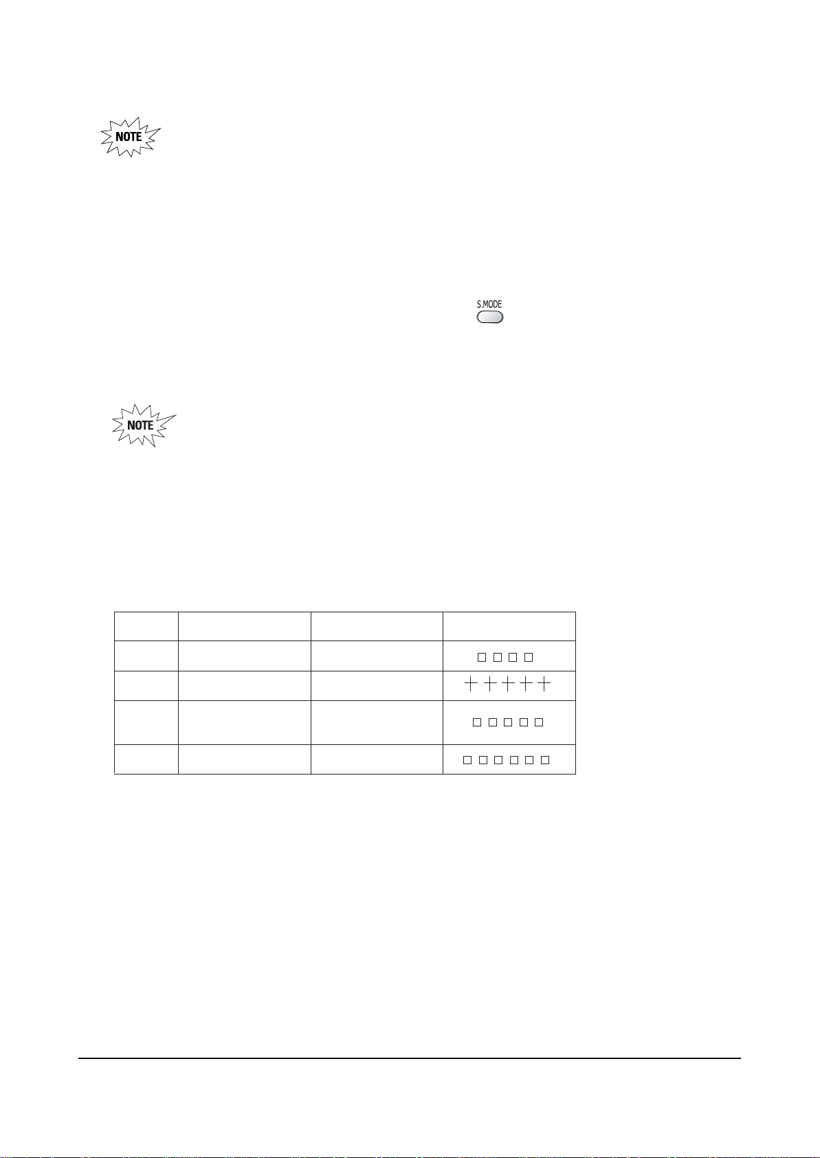
(Factory Mode). Auto Covergence is porformed in the following sequences :
GRB
Up, Down Left, Right
When auto Convergence is complete, the data is automatically saved and the convergence
pattern revets.
Convergence must be adjusted and saved correctly before Perfect Focus can be performed.
Otherwise, a “No Sense Data” error message will appear.
130
245
150
130
245
150
Alignment and Adjustments
2-24 Samsung Electronics
• After Factory Auto convergence is complete, make sure that the cursor flickers for about
` 1 second on the center and then it is saved.
• OSD shows error.
• When any error happens, be sure to re-do Factory Auto Convergence.
• When Convergence Adjustment is not normally done or the convergence center is
misaligned with the sensing point, any adjustment error happens. Therefore, be sure to use
a screen jig to correctly adjust during troubleshooting.
2. After the Convergence Adjustments are completde, press the key to exit.
3. DTV Convergence adjustment must be done same as the above Normal Mode Convergence Adjustment
(Use a 16 : 9 screen jig for DTV)
When Convergence Adjustment is not normally done or the convergence center is
misaligned with the sensing point, any adjustment error happens. Therefore, be sure to
use a screen jig to correctly adjust during troubeshooting.
■ Changes when applying Almighty-Cg, Module (How to extract the basic Cg Data)
47"
52"
55"
65"
Model NameInch
CN479W 5- 473
HCN529W 5- 521
HCN559W
HCN5529W
HCN659W 5- 653
Data Screen Display
5- 553

Alignment and Adjustments
Samsung Electronics 2-25
2-9 PIN SPEC
2-9-1 D-MODULE PIN
CN101 CN102
1 3.3V-D_1 17 SDA-EE PROM 33 GND 49 STD-5V_1 65 DT V-VO 81 GND
2 3.3V-D_2 18 TSCH-D7 34 GND 50 SC L-M5 66 COMP1-Pr 82 SURR-L
3 3.3V-D_3 19 TSCH-D6 35 SA M-YO 51 STD-5V_2 67 GND 83 SU B-C
4 GND 20 TSCH-D5 36 TU-RST 52 SDA-M5 68 COMP1-Pb 84 GND
5 GND 21 TSCH-D4 37 SAM-PbO 53 GND 69 GND 85 GND
6 5V-D1_1 22 TSCH-D3 38 DVI-ID 54 GND 70 COMP1-Y 86 CENTER
7 5V-D1_2 23 TSCH-D2 39 SAM- PrO 55 NC 71 MAIN-Y 87 TV-L
8 GND 24 TSCH-D1 40 AGC - SW 56 GND 72 GND 88 GND
9 GND 25 TSCH-D0 41 GND 57 GND 73 GND 89 TV-R
10 12V 26 GND 42 I2S-CLK 58 COMP 2-Pr 74 MAIN-FRO 90 WO OFER
11 NT2 - V 27 TSC H1 - VLD 43 SA M-HSO 59 SDA - MICOM 75 MAIN-C 91 I2S-MCLK
12 S-RESET 28 TSCH1-CLK 44 I2S-LRCLK 60 COMP2-Pb 76 MAIN-FLO 92 2RF- S
13 NC 29 TSCH1-SYNC 45 SA M-VSO 61 SCL-MICOM 77 GND 93 DTV- LTO
14 AMP-MUTE 30 BUS- STOP 46 SCL-M 62 COMP2-Y 78 GND 94 GND
15 CPU _RESET 31 NC 47 GND 63 GND 79 SU B-V/ Y 95 DTV- RTO
No. NAME No. NAME No. NAME No. NAME No. NAME No. NAME
16 SCL-EEPROM 32 GND 48 SDA - M 64 GND 80 SURR-R 96 GND

Alignment and Adjustments
2-26 Samsung Electronics
2-9-2 MV-MODULE / CG-MODULE PIN
CN700
CG-MODULE PIN SPEC
1 5V-CG 17 GND
2 GND 18 GND
No. NAME No. NAME
3 D/F 19 BV
4 GND 20 BH
5 SC L-M5 21 GV
6 CG-F/B 22 GH
7 GND 23 RV
8NC24RH
9 CG-R 25 GND
10 CG-G 26 H-BLK
11 CG-B 27 V-BLK
12 SDA-M5 28 GND
13 NC 29 NC
14 IR 30 -5V
15 CG-F/B 31 5V
16 GND 32 GND
CN202
MV-MODULE PIN SPEC
1 13 .5 V 17 HD 33 GND 49 IR
2 SAM - HSO 18 CG-G 34 GND 50 ST B-5V
3 GND 19 GND 35 MICOM-D6 51 GND
4 SA M-VSO 20 CG-B 36 POWER 52 GND
5 D/F 21 AB L 37 MICOM-D4 53 KEY3
6 GND 22 CG-F/B 38 MICOM-D5 54 V-BLK
7 VM-Y 23 5V 39 MICOM-D2 55 KEY1
8 SAM- PrO 24 SCL-M5 40 MICOM-D3 56 H- BLK
9 GND 25 9V 41 MICOM-D0 57 KEY2
10 SA M-PbO 26 SDA - M5 42 MICOM-D1 58 GND
11 VD+ 27 GND 43 GND 59 GND
12 SAM-YO 28 GND 44 MICOM-INT 60 SCL-MICOM
13 VD- 29 COMB-C 45 TIMER-LED 61 CAPTION-V/Y
14 GND 30 MAIN-C 46 CPU - RESET 62 SDA - MICOM
15 EW 31 COMB-V/Y 47 STB-LED 63 1080I-SW
No. NAME No. .NAME No. NAME No NAME
16 CG-R 32 MAIN-Y 48 PROTECT 64 GND

3. Exploded View & Parts List
3-1 HCN5529WX/XAA
Exploded View & Parts List
Samsung Electronics 3-1
1 BP64-00210B CABINET FRONT-MASK;55W7,HIPS,HB,GRY,DGM1 1 T0017 S.N.A
2 BP64-00211B CABINET FRONT-BOT;55W7,HIPS,V0,G4309,SV0 1 S.N.A
3 AA67-00132A SUN SCREEN-AG;55W,1251*712*,T=82%,G=110 1 T0110
4 AA67-00124B SCREEN FRESNEL;55W,1251*712,T2 1 T0053
5 AA67-00200A SCREEN-TINT;55W,1249*710,T=0.7,P 1 T0056
6 BP61-00351A HOLDER-SCREEN TOP ASSY;HIPS,55W7,HB,BLK, 1 S.N.A
7 BP61-00352A HOLDER-SCREEN SIDE ASSY;HIPS,47/55W7,HB, 2 S.N.A
8 AA60-00091R SPACER-FELT;,FELT,250X10,,,BLK,T0.5,, 2 T0069 S.N.A
9 BP96-00333A ASSY COVER P-WOOD;55W7,WOOD,SEA 1 S.N.A
10 AA64-02065C CABINET-BACK,SIDE;47.55W3,HIPS V0,BLK 2 T0111
11 BP64-00205A KNOB CONTROL;47W7,ABS HB,G3676,SVM3132 1 T0022 S.N.A
12 AA91-00762D ASSY-JACK,SIDE;,P54A PAL XAA,W3 1 T0014
13 BP91-00491A ASSY PRT;HCM5525WX/XAA,P55A 1 S.N.A
14 AA60-00072B SPACER-COVER,DUST;43,54,62J9,SPONGE 94HF 1 S.N.A
15 AA67-00206A MIRROR-FRONT;55W9,FSM,1027*799*540 1
16 AA61-01091A BRACKET-FRAME,MIRROR L;55W9,SECC,T1.6,BL 1 S.N.A
17 AA61-01090A BRACKET-FRAME,MIRROR R;55W9,SECC,T1.6,BL 1 S.N.A
18 AA63-00021L SPACER-MIRROR,TOP;50J6,PVC HB,BLK,L1020 1 S.N.A
19 AA63-00021K SPACER-MIRROR;50J6,PVC,BLK,HB L500 1 S.N.A
20 AA63-00021M SPACER-MIRROR,BOT;50J6,PVC HB,L799,BLK 1 S.N.A
21 AA63-00021K SPACER-MIRROR;50J6,PVC,BLK,HB L500 1 S.N.A
22 AA61-01092A BRACKET-MIRROR,TOP;55W9,SECC,T1.0,BLK 1 S.N.A
23 AA61-01093A BRACKET-MIRROR,BOT;55W9,SECC,T1.0 1 S.N.A
24 BP64-00048A CABINET-BACK,TOP;55W3,HIPS,HB,BLK 1 T0112
25 BP64-00203A CABINET BACK-BOT;47W7,HIPS V0,BLK 1 T0015 S.N.A
26 AA61-01127A HOLDER-CHASSIS;COMMANDO,HIPS V0,G4309 1 T0070 S.N.A
27 BP94-00505U ASSY PCB MISC-PWR-DEF;HCN5529WX/XAA,P58A 1 T0097
28 BP95-00142B ASSY SUB PCB-DTV MODULE;HCN559WX/XAA,P58A 1
29 BP96-00275A ASSY COVER P-TERMINAL ANT;55W3,HIPS,VO,B 1 T0130 S.N.A
30 BP94-00445G ASSY PCB MAIN;SVP-55W3HD ,P58A 1 T0073
31 BP95-00142C ASSY SUB PCB-M/V-MODULE;HCN559WX/XAA,P58A 1
32 BP95-00142A ASSY SUB PCB-CG MODULE;HCN559WX/XAA,P58A 1
33 BP94-00503B ASSY PCB CRT-PCB-P58A 1
No Code No Description;Specification Q’ty Remark S.N.A
You can search for the updated part code through ITSELF web site.
URL : http://itself.sec.samsung.co.kr

Exploded View & Parts List
3-2 Samsung Electronics
3-2 HCN559WX/XAA
1 AA64-02059Q CABINET FRONT-MASK;559W,HIPS,HB,GRY,DGM1 1 T0017
2 BP96-00308C ASSY COVER P-FRONT BOT;55W3,HIPS,V0,GRY, 1 S.N.A
3 AA91-00757K ASSY-DOOR RACK;W3,CIS,GRY,HIPS,HB,SVM113 1 T0013
4 AA61-00859B PLATE-CENTER;W3,WOOD,T12,MDF 1 S.N.A
5 AA67-00132A SUN SCREEN-AG;55W,1251*712*,T=82%,G=110 1 T0110
6 AA67-00124B SCREEN FRESNEL;55W,1251*712,T2 1 T0053
7 AA67-00200A SCREEN-TINT;55W,1249*710,T=0.7,P 1 T0056
8 BP96-00106G ASSY MISC P-CABINET WOOD;559W,WOOD 1 S.N.A
9 AA64-02065C CABINET-BACK,SIDE;47.55W3,HIPS V0,BLK 2 T0111
10 BP61-00275B HOLDER-SCREEN TB;ABS HB,W3,L1282,BLK,CAN 2 S.N.A
11 AA91-00762D ASSY-JACK,SIDE;,P54A PAL XAA,W3 1 T0014
12 AA61-00475B BRACKET-CRT,MAIN;54,SECC,T1.6,-,-,-,- 1 T0115
13 AA60-00072B SPACER-COVER,DUST;43,54,62J9,SPONGE 94HF 1 S.N.A
14 AA67-00206A MIRROR-FRONT;55W9,FSM,1027*799*540 1
15 AA61-01091A BRACKET-FRAME,MIRROR L;55W9,SECC,T1.6,BL 1 S.N.A
16 AA61-01090A BRACKET-FRAME,MIRROR R;55W9,SECC,T1.6,BL 1 S.N.A
17 AA63-00021L SPACER-MIRROR,TOP;50J6,PVC HB,BLK,L1020 1 S.N.A
18 AA63-00021K SPACER-MIRROR;50J6,PVC,BLK,HB L500 1 S.N.A
19 BP61-00034A BRACKET-MIRROR(BOT);DP,553W,61-01093A 1 BRA/MB
20 AA63-00021M SPACER-MIRROR,BOT;50J6,PVC HB,L799,BLK 1 S.N.A
21 AA61-01092A BRACKET-MIRROR,TOP;55W9,SECC,T1.0,BLK 1 S.N.A
22 AA61-01093A BRACKET-MIRROR,BOT;55W9,SECC,T1.0 1 S.N.A
23 BP64-00048A CABINET-BACK,TOP;55W3,HIPS,HB,BLK 1 T0112
24 AA64-02266A CABINET-BACK,BOT;J8,HIPS,V0,BLK 1 T0112
25 BP91-00769Z ASSY CHASSIS;HCN559W3,P58A 1 M0017
26 BP94-00505U ASSY PCB MISC-PWR-DEF;HCN5529WX/XAA,P58A 1 T0097
27 BP95-00142B ASSY SUB PCB-DTV MODULE;HCN559WX/XAA,P58A 1
28 BP96-00275A ASSY COVER P-TERMINAL ANT;55W3,HIPS,VO,B 1 T0130 S.N.A
29 BP94-00445G ASSY PCB MAIN;SVP-55W3HD ,P58A 1 T0073
30 BP95-00142C ASSY SUB PCB-M/V-MODULE;HCN559WX/XAA,P58A 1
31 BP95-00142A ASSY SUB PCB-CG MODULE;HCN559WX/XAA,P58A 1
32 BP94-00503B ASSY PCB CRT-PCB-P58A 1
No Code No Description;Specification Q’ty Remark S.N.A
You can search for the updated part code through ITSELF web site.
URL : http://itself.sec.samsung.co.kr

Exploded View & Parts List
Samsung Electronics 3-3
3-3 HCN529WX/XAA
1 BP64-00116G CABINET FRONT-MASK;52Q7,HIPS,HB,GRY,DGM1 1 T0017 S.N.A
2 BP64-00178A BADGE-BRAND;ALL,AL,T1.5,78,13.0,,BLK,SIL 1 T0057 S.N.A
3 BP67-00048A SUN SCREEN-AG;52Q7,G110,T82,1175*673*2 1 T0110
4 BP64-00115A CABINET-FRONT,TOP;52Q7,HIPS HB,GRY,SV012 1 T0245
5 BP61-00158A HOLDER-SENSOR;52Q7,PC,VIOLET 4 S.N.A
6 BP61-00156A BRACKET-MIRROR,SIDE(L);52Q7,SECC 1.0 1 S.N.A
7 BP61-00157A BRACKET-MIRROR,SIDE(R);52Q7,SECC 1.0 1 S.N.A
8 BP61-00154A BRACKET-MIRROR,TOP;52Q7,SECC 1.0 1 S.N.A
9 BP61-00155A BRACKET-MIRROR,BOTTOM;52Q7,SECC 1.0 1 S.N.A
10 BP64-00120A CABINET-BACK,TOP;52Q7,HIPS,HB 1 T0112
11 BP64-00121B CABINET BACK-BOT;52Q7,HIPS,V0 1 T0015 S.N.A
12 BP96-00275A ASSY COVER P-TERMINAL ANT;55W3,HIPS,VO,B 1 T0130 S.N.A
13 BP94-00445G ASSY PCB MAIN;SVP-55W3HD ,P58A 1 T0073
14 AA26-00101A TRANS FBT-H/V DISTRIBUTOR;FWZ50A001E/FFA 1 T0118
15 AA60-00123B SPACER-COVER,DUST;W3,PS SHEET,T0.35 1 S.N.A
16 AA61-00475B BRACKET-CRT,MAIN;54,SECC,T1.6,-,-,-,- 1 T0115
17 BP91-00820L ASSY CPT-R;P58A 1 T0026
BP91-00507A ASSY CPT-G;HCM5525WX/XAA,P55A,G 1 T0027
BP91-00505A ASSY CPT-B;HCM5525WX/XAA,P55A,B 1 T0028
18 BP64-00156A CABINET-WOOD;52Q7,WOOD 1 S.N.A
19 BP64-00119B CABINET FRONT-BOT;52Q7,HIPS,V0,GRY,SV012 1 T0016
20 BP61-00159A HOLDER-A/V;Q7,ABS HB,SV012P 1 S.N.A
21 AA64-02780G DOOR-A/V;43T8,ABS,HB,SV012P 1 T0150
22 BP59-00030A MODULE-FOCUS PACK ASSY;PJT TV,J302-P03A, 1 S.N.A
23 BP94-00575A ASSY PCB MISC-CONTROL;HCN529WX/XAA,P58A, 1 T0098
24 BP64-00128B INDICATOR-LED;47,52Q7,PC CLEAR,,,,, 1 T0071 S.N.A
25 BP64-00125A WINDOW-RMC;52Q7,ABS,WHT 1 S.N.A
26 BP64-00122A CABINET-BOSS;52Q7,ABS HB,BLK 2 S.N.A
27 BP64-00117F CABINET-PANEL MID;52Q7,ABS,HB,D-GRY,DGM2 1 S.N.A
28 BP64-00127A KNOB-SIDE,COVER;52Q7,AL T1.0 1 S.N.A
29 BP64-00123A KNOB POWER;52Q7,ABS HB,D-GRY,DGM2256 1 T0023 S.N.A
30 BP64-00126A KNOB POWER-COVER;52Q7,AL T1.0 1 S.N.A
31 BP64-00118A CABINET-PANNEL,BOTTOM;52Q7,HIPS HB,GRY,S 1 T0211
32 BP94-00505U ASSY PCB MISC-PWR-DEF;HCN5529WX/XAA,P58A 1 T0097
33 BP95-00142C ASSY SUB PCB-M/V-MODULE;HCN559WX/XAA,P58A 1
34 BP95-00142B ASSY SUB PCB-DTV MODULE;HCN559WX/XAA,P58A 1
35 BP95-00142A ASSY SUB PCB-CG MODULE;HCN559WX/XAA,P58A 1
No Code No Description;Specification Q’ty Remark S.N.A
You can search for the updated part code through ITSELF web site.
URL : http://itself.sec.samsung.co.kr

ASSY CHASSIS
1 M0017 BP91-00915A ASSY CHASSIS;HCN5529WX/XAA,P58A,DVI
..2 T0105 AA94-08270A ASSY PCB MISC-DY JACK;COMMANDO
...3 AA97-07230N ASSY AUTO;COMMANDO S.N.A
....4 R301 2001-001107 R-CARBON(S);220ohm,5%,1/2W,AA,TP,2.4x6.4
....4 R302 2001-001107 R-CARBON(S);220ohm,5%,1/2W,AA,TP,2.4x6.4
....4 R303 2001-001107 R-CARBON(S);220ohm,5%,1/2W,AA,TP,2.4x6.4
....4 PCB AA41-00632A PCB-DY CONNECTION;HCM4215W,FR-1,1L,A,1.6 S.N.A
...3 0202-000187 SOLDER-WIRE FLUX;-,RS60S,D1.2,63Sn/37Pb S.N.A
...3 GT01 AA60-40012D PIN-GT,ASSY;T1.6,6-12.5-,NYLON66 S.N.A
...3 GT05 AA60-40012D PIN-GT,ASSY;T1.6,6-12.5-,NYLON66 S.N.A
...3 GT09 AA60-40012D PIN-GT,ASSY;T1.6,6-12.5-,NYLON66 S.N.A
...3 GT13 AA60-40012D PIN-GT,ASSY;T1.6,6-12.5-,NYLON66 S.N.A
...3 AA61-01197A HOLDER-PCB,DY;COMANDO,ABS V0,BLK S.N.A
..2 T0101 BP94-00134E ASSY PCB MISC-SENSOR ASSY;SENSOR
...3 0202-000187 SOLDER-WIRE FLUX;-,RS60S,D1.2,63Sn/37Pb S.N.A
...3 CN906 3711-000447 CONNECTOR-HEADER;BOX,3P,1R,2.5MM,ANGLE,...3 BP97-00208A ASSY SMD;0 S.N.A
....4 Q01 0501-000342 TR-SMALL SIGNAL;KSC1623-Y,NPN,200mW,SOT-
....4 PCB AA41-00853A PCB-SERSOR;SVP-42W5HRC,FR-4,2L,A,1.6T,24 S.N.A
....4 D01 BP32-00001A SENSOR PHOTO;BCS5030G1,-40 TO +85,0.42 U
....4 R01 2007-000305 R-CHIP;10Mohm,5%,1/10W,TP,1608
....4 R02 2007-000109 R-CHIP;1Mohm,5%,1/10W,TP,1608
....4 R03 2007-000109 R-CHIP;1Mohm,5%,1/10W,TP,1608
....4 0202-001167 SOLDER-CREAM;RX3603-2330HO,S45A,PASTE,SN S.N.A
..2 T0073 BP94-00445G ASSY PCB MAIN;SVP-55W3HD ,P58A
...3 0202-000187 SOLDER-WIRE FLUX;-,RS60S,D1.2,63Sn/37Pb S.N.A
...3 T0083 0402-000586 DIODE-RECTIFIER;RK49,90V,3.5A,DO-201AD
...3 IC804 1203-000119 IC-NEGA.FIXED REG.;7905,TO-220,3P,-,PLAS
...3 IC012 1203-000165 IC-POSI.ADJUST REG.;78R12,TO-220,4P,-,PL
...3 C701 2401-000737 C-AL;2200uF,20%,50V,GP,TP,18x35.5,7
...3 C701 2401-000737 C-AL;2200uF,20%,50V,GP,TP,18x35.5,7
...3 C701 2401-000737 C-AL;2200uF,20%,50V,GP,TP,18x35.5,7
...3 C701 2401-001068 C-AL;3300uF,20%,50V,GP,BK,22x40,10
...3 X600 2801-004020 CRYSTAL-UNIT;18.432MHz,30ppm,28-AAM,12pF
...3 CN102 3703-001150 CONNECTOR-BACK PANEL;32P,2R,FEMALE,STRAI
...3 CN700 3703-001150 CONNECTOR-BACK PANEL;32P,2R,FEMALE,STRAI
...3 CN202 3703-001187 CONNECTOR-BACK PANEL;64P,2R,FEMALE,STRAI
...3 CN101 3703-001187 CONNECTOR-BACK PANEL;64P,2R,FEMALE,STRAI
...3 CN906 3711-002642 CONNECTOR-HEADER;BOX,3P,1R,2.5mm,STRAIGH
...3 CN906 3711-002642 CONNECTOR-HEADER;BOX,3P,1R,2.5mm,STRAIGH
...3 CN906 3711-002643 CONNECTOR-HEADER;BOX,4P,1R,2.5mm,STRAIGH
...3 JA702 3722-001163 JACK-VHS;4P,12mm,AU,BLK,N
...3 JA700 3722-001426 JACK-PIN;9P,3.4mm,NI,BLK,...3 JA703 3722-001795 JACK-PIN;10P(10P),-,NI,RD/WH/RD/BL/GN*2,
...3 L800 AA27-10001C COIL CHOKE;-,100uH,K,-,5.0A,ST,700UH-K(R
...3 L805 AA27-10001C COIL CHOKE;-,100uH,K,-,5.0A,ST,700UH-K(R
...3 L806 AA29-00004A FILTER LINE NOISE;-,20UH,3A,AC80-260V,TQ
...3 TU101 AA59-00164A MODULE-RF,SPLITTER;-,UMX-NT-005,-,2IN/3O
...3 AA63-00396B SHIELD CASE-TOP;PRJT,P54A,SPTE,T0.5,-,-, S.N.A
...3 AA63-00397B SHIELD CASE-BOT;PRJT,P54A,SPTE,T0.5,-,-, S.N.A
...3 AA63-00608A SHIELD CASE;HERCULES TOP,SPTE,T0.5,W140. S.N.A
...3 AA63-00610A SHIELD CASE;COMMANDO,SPTE,T0.5,W141.5,H1 S.N.A
...3 IC800 AA96-00475C ASSY H/S;SILICON-OIL,KA278R09,KA7808,AA6 S.N.A
....4 0205-000129 GREASE-SILICON;SC102,JAPAN S.N.A
....4 T0087 1203-000293 IC-POSI.FIXED REG.;7808,TO-220,3P,-,PLAS
....4 T0123 1203-002003 IC-VOLTAGE REGULATOR;278R09,TO-220,4P,-,
....4 T0081 6003-000334 SCREW-TAPTITE;RH,+,2S,M3,L6,ZPC(YEL),SWR
....4 AA62-00066B HEAT SINK;D2,D3,AL ,T1.0,89,70,-,AA62-00 S.N.A
....4 T0123 1203-001978 IC-VOLTAGE REGULATOR;KA278RA05,TO-220F,4
...3 IC604 AA96-00623E ASSY H/S;SCREW,MAIN,AA62-00056A,TDA7265, S.N.A
....4 0205-000129 GREASE-SILICON;SC102,JAPAN S.N.A
....4 T0124 1201-001026 IC-POWER AMP;7265,ZIP,11P,19.6MIL,DUAL,1
....4 T0081 6003-000334 SCREW-TAPTITE;RH,+,2S,M3,L6,ZPC(YEL),SWR
....4 AA62-00056A HEAT SINK-PS;-,-,T1.0,-,41*35*70,D2,-,-, S.N.A
...3 IC802 BP96-00020G ASSY HEAT SINK P;AA62-00045B,TAPTITE,SI- S.N.A
....4 CIS 0205-000129 GREASE-SILICON;SC102,JAPAN S.N.A
....4 T0081 6003-000334 SCREW-TAPTITE;RH,+,2S,M3,L6,ZPC(YEL),SWR
....4 CIS AA62-00045B HEAT SINK;COMMANDO,AL1050,T1.0,H45.0 S.N.A
....4 IC012 1203-000203 IC-POSI.ADJUST REG.;3050,TO-220,5P,-,PLA
...3 IC803 BP96-00020K ASSY HEAT SINK P;H/S TR,SCREW,SI-8033S,O S.N.A
....4 CIS 0205-001027 OIL-SILICON;G746,-,- S.N.A
....4 CIS 1203-002670 IC-SWITCH VOL. REG.;SI-8033S,TO-220,5P,1
....4 T0081 6003-000335 SCREW-TAPTITE;RH,+,2S,M3,L8,ZPC(YEL),SWR S.N.A
....4 AA62-00045A HEAT SINK-PS;-,-,T1.0,-,-,DREAM,-,-,-,-, S.N.A
...3 BP97-00461A ASSY AUTO-MAIN;SVP-55W3HD,P58A
....4 D608 0401-000005 DIODE-SWITCHING;1N4148,100V,200mA,DO-35,
....4 D606 0401-000005 DIODE-SWITCHING;1N4148,100V,200mA,DO-35,
....4 D605 0401-000005 DIODE-SWITCHING;1N4148,100V,200mA,DO-35,
....4 D604 0401-000005 DIODE-SWITCHING;1N4148,100V,200mA,DO-35,
....4 D603 0401-000005 DIODE-SWITCHING;1N4148,100V,200mA,DO-35,
....4 D600 0401-000005 DIODE-SWITCHING;1N4148,100V,200mA,DO-35,
....4 T0083 0402-000546 DIODE-RECTIFIER;TVR10G,400V,1.0A,DO-41,T
....4 DZ016 0403-000700 DIODE-ZENER;TZP33A,33V,31-35V,1W,DO-41,T
....4 DZ016 0403-001039 DIODE-ZENER;MA2560,56V,52-60V,1W,DO-41,T
....4 DZ016 0403-001319 DIODE-ZENER;MTZJ4.7C,4.68-4.93V,500mW,DO
....4 DZ016 0403-001325 DIODE-ZENER;MTZJ15C,14.35-15.09V,500mW,D
....4 Q605 0501-000389 TR-SMALL SIGNAL;KSC815,NPN,400mW,TO-92,T
....4 Q604 0501-000389 TR-SMALL SIGNAL;KSC815,NPN,400mW,TO-92,T
....4 Q600 0501-000389 TR-SMALL SIGNAL;KSC815,NPN,400mW,TO-92,T
....4 R649 2001-000007 R-CARBON;3KOHM,5%,1/8W,AA,TP,1.8X3.2MM
....4 R674 2001-000008 R-CARBON;15KOHM,5%,1/8W,AA,TP,1.8X3.2MM
....4 R807 2001-000066 R-CARBON(S);10KOHM,5%,1/2W,AA,TP,2.4X6.4
....4 R810 2001-000066 R-CARBON(S);10KOHM,5%,1/2W,AA,TP,2.4X6.4
....4 R812 2001-000107 R-CARBON(S);150KOHM,5%,1/2W,AA,TP,2.4X6.
....4 R651 2001-000273 R-CARBON;100KOHM,5%,1/8W,AA,TP,1.8X3.2MM
....4 R670 2001-000290 R-CARBON;10KOHM,5%,1/8W,AA,TP,1.8X3.2MM
....4 R660 2001-000290 R-CARBON;10KOHM,5%,1/8W,AA,TP,1.8X3.2MM
....4 R655 2001-000290 R-CARBON;10KOHM,5%,1/8W,AA,TP,1.8X3.2MM
....4 R654 2001-000290 R-CARBON;10KOHM,5%,1/8W,AA,TP,1.8X3.2MM
....4 R677 2001-000331 R-CARBON;12KOHM,5%,1/8W,AA,TP,1.8X3.2MM
....4 R814 2001-000508 R-CARBON;220KOHM,5%,1/8W,AA,TP,1.8X3.2MM
....4 R813 2001-000522 R-CARBON;22KOHM,5%,1/8W,AA,TP,1.8X3.2MM
....4 R656 2001-000522 R-CARBON;22KOHM,5%,1/8W,AA,TP,1.8X3.2MM
....4 R650 2001-000660 R-CARBON;33KOHM,5%,1/8W,AA,TP,1.8X3.2MM
....4 R648 2001-000734 R-CARBON;4.7KOHM,5%,1/8W,AA,TP,1.8X3.2MM
....4 R646 2001-000734 R-CARBON;4.7KOHM,5%,1/8W,AA,TP,1.8X3.2MM
....4 R645 2001-000734 R-CARBON;4.7KOHM,5%,1/8W,AA,TP,1.8X3.2MM
....4 R806 2001-000739 R-CARBON;4.7MOHM,5%,1/8W,AA,TP,1.8X3.2MM
....4 R805 2001-000739 R-CARBON;4.7MOHM,5%,1/8W,AA,TP,1.8X3.2MM
....4 R802 2001-000739 R-CARBON;4.7MOHM,5%,1/8W,AA,TP,1.8X3.2MM
....4 R801 2001-000739 R-CARBON;4.7MOHM,5%,1/8W,AA,TP,1.8X3.2MM
....4 R800 2001-000739 R-CARBON;4.7MOHM,5%,1/8W,AA,TP,1.8X3.2MM
....4 R653 2001-000780 R-CARBON;470OHM,5%,1/8W,AA,TP,1.8X3.2MM
....4 R652 2001-000780 R-CARBON;470OHM,5%,1/8W,AA,TP,1.8X3.2MM
....4 R637 2001-000812 R-CARBON;5.6KOHM,5%,1/8W,AA,TP,1.8X3.2MM
....4 R638 2001-000812 R-CARBON;5.6KOHM,5%,1/8W,AA,TP,1.8X3.2MM
....4 R661 2001-000812 R-CARBON;5.6KOHM,5%,1/8W,AA,TP,1.8X3.2MM
....4 R760 2001-000812 R-CARBON;5.6KOHM,5%,1/8W,AA,TP,1.8X3.2MM
....4 R678 2001-001000 R-CARBON;82KOHM,5%,1/8W,AA,TP,1.8X3.2MM
....4 R675 2001-001146 R-CARBON(S);4.7OHM,5%,1/2W,AA,TP,2.4X6.4
....4 R676 2001-001146 R-CARBON(S);4.7OHM,5%,1/2W,AA,TP,2.4X6.4
....4 R809 2003-001098 R-METAL OXIDE(S);22Kohm,5%,3W,AA,TP,6x16
....4 R668 2004-001390 R-METAL(S);1Kohm,2%,1/2W,AA,TP,2.4x6.4mm
....4 R671 2004-001390 R-METAL(S);1Kohm,2%,1/2W,AA,TP,2.4x6.4mm
....4 R673 2004-001970 R-METAL(S);1.8Kohm,1%,1/2W,AA,TP,6.5x2.5
....4 R669 2004-001970 R-METAL(S);1.8Kohm,1%,1/2W,AA,TP,6.5x2.5
....4 R667 2004-001970 R-METAL(S);1.8Kohm,1%,1/2W,AA,TP,6.5x2.5
....4 R665 2004-001970 R-METAL(S);1.8Kohm,1%,1/2W,AA,TP,6.5x2.5
....4 C677 2301-000192 C-FILM,PEF;1nF,5%,50V,TP,5.3x10mm,5mm
....4 C676 2301-000192 C-FILM,PEF;1nF,5%,50V,TP,5.3x10mm,5mm
....4 C690 2305-000665 C-FILM,MPEF;100nF,5%,63V,TP,7.5x4.0x5.0m
....4 C689 2305-000665 C-FILM,MPEF;100nF,5%,63V,TP,7.5x4.0x5.0m
....4 C680 2305-000665 C-FILM,MPEF;100nF,5%,63V,TP,7.5x4.0x5.0m
....4 C701 2401-000025 C-AL;100uF,20%,16V,GP,TP,6.3x11,5
Samsung Electronics 4-1
Electrical Parts List
Loc. No. Code No. Description ; Specification Remark Loc. No. Code No. Description ; Specification Remark
4. Electrical Parts List
4-1 HCN5529WX/XAA

....4 C701 2401-000025 C-AL;100uF,20%,16V,GP,TP,6.3x11,5
....4 C701 2401-000031 C-AL;47uF,20%,16V,GP,TP,5x11,5
....4 C701 2401-000039 C-AL;1000uF,20%,16V,GP,TP,10x16,5
....4 C701 2401-000302 C-AL;100uF,20%,25V,GP,TP,6.3x11,5
....4 C701 2401-000360 C-AL;100uF,20%,50V,GP,TP,8x11.5,5
....4 C701 2401-000360 C-AL;100uF,20%,50V,GP,TP,8x11.5,5
....4 C701 2401-000455 C-AL;10uF,20%,35V,GP,TP,4x7mm,5mm
....4 C701 2401-000471 C-AL;10uF,20%,50V,BP,TP,5x11,5mm
....4 C701 2401-000480 C-AL;10uF,20%,50V,GP,TP,5x11,5
....4 C701 2401-000480 C-AL;10uF,20%,50V,GP,TP,5x11,5
....4 C701 2401-000480 C-AL;10uF,20%,50V,GP,TP,5x11,5
....4 C701 2401-000480 C-AL;10uF,20%,50V,GP,TP,5x11,5
....4 C701 2401-000480 C-AL;10uF,20%,50V,GP,TP,5x11,5
....4 C701 2401-000480 C-AL;10uF,20%,50V,GP,TP,5x11,5
....4 C701 2401-000480 C-AL;10uF,20%,50V,GP,TP,5x11,5
....4 C701 2401-000480 C-AL;10uF,20%,50V,GP,TP,5x11,5
....4 C701 2401-000480 C-AL;10uF,20%,50V,GP,TP,5x11,5
....4 C701 2401-000480 C-AL;10uF,20%,50V,GP,TP,5x11,5
....4 C701 2401-000480 C-AL;10uF,20%,50V,GP,TP,5x11,5
....4 C701 2401-000480 C-AL;10uF,20%,50V,GP,TP,5x11,5
....4 C701 2401-000480 C-AL;10uF,20%,50V,GP,TP,5x11,5
....4 C701 2401-000480 C-AL;10uF,20%,50V,GP,TP,5x11,5
....4 C701 2401-000480 C-AL;10uF,20%,50V,GP,TP,5x11,5
....4 C701 2401-000480 C-AL;10uF,20%,50V,GP,TP,5x11,5
....4 C701 2401-000480 C-AL;10uF,20%,50V,GP,TP,5x11,5
....4 C701 2401-000480 C-AL;10uF,20%,50V,GP,TP,5x11,5
....4 C701 2401-000480 C-AL;10uF,20%,50V,GP,TP,5x11,5
....4 C701 2401-000480 C-AL;10uF,20%,50V,GP,TP,5x11,5
....4 C701 2401-000603 C-AL;1UF,20%,50V,GP,TP,5X11,2
....4 C701 2401-000603 C-AL;1UF,20%,50V,GP,TP,5X11,2
....4 C701 2401-000603 C-AL;1UF,20%,50V,GP,TP,5X11,2
....4 C701 2401-000698 C-AL;2200uF,20%,16V,WT,TP,12.5x25,5
....4 C701 2401-000698 C-AL;2200uF,20%,16V,WT,TP,12.5x25,5
....4 C701 2401-000832 C-AL;220uF,20%,25V,GP,TP,8x11.5,5
....4 C701 2401-000962 C-AL;22uF,20%,50V,GP,TP,5x11,5
....4 C701 2401-000962 C-AL;22uF,20%,50V,GP,TP,5x11,5
....4 C701 2401-000962 C-AL;22uF,20%,50V,GP,TP,5x11,5
....4 C701 2401-000962 C-AL;22uF,20%,50V,GP,TP,5x11,5
....4 C701 2401-000962 C-AL;22uF,20%,50V,GP,TP,5x11,5
....4 C701 2401-000962 C-AL;22uF,20%,50V,GP,TP,5x11,5
....4 C701 2401-000962 C-AL;22uF,20%,50V,GP,TP,5x11,5
....4 C701 2401-000962 C-AL;22uF,20%,50V,GP,TP,5x11,5
....4 C701 2401-000962 C-AL;22uF,20%,50V,GP,TP,5x11,5
....4 C701 2401-000962 C-AL;22uF,20%,50V,GP,TP,5x11,5
....4 C701 2401-000962 C-AL;22uF,20%,50V,GP,TP,5x11,5
....4 C701 2401-000962 C-AL;22uF,20%,50V,GP,TP,5x11,5
....4 C701 2401-000962 C-AL;22uF,20%,50V,GP,TP,5x11,5
....4 C701 2401-001397 C-AL;470uF,20%,25V,GP,TP,10x16,5
....4 C701 2401-001989 C-AL;4.7uF,20%,50V,BP,TP,5x11,5
....4 C701 2401-001989 C-AL;4.7uF,20%,50V,BP,TP,5x11,5
....4 C701 2401-001989 C-AL;4.7uF,20%,50V,BP,TP,5x11,5
....4 C701 2401-001989 C-AL;4.7uF,20%,50V,BP,TP,5x11,5
....4 C701 2401-002009 C-AL;100uF,20%,16V,GP,TP,6.3x7,5
....4 C701 2401-002009 C-AL;100uF,20%,16V,GP,TP,6.3x7,5
....4 C701 2401-002009 C-AL;100uF,20%,16V,GP,TP,6.3x7,5
....4 C701 2401-002009 C-AL;100uF,20%,16V,GP,TP,6.3x7,5
....4 C701 2401-002009 C-AL;100uF,20%,16V,GP,TP,6.3x7,5
....4 C701 2401-002075 C-AL;4.7uF,20%,50V,GP,TP,5x11,5
....4 C701 2401-002144 C-AL;47uF,20%,16V,GP,TP,5x11,5
....4 C701 2401-002144 C-AL;47uF,20%,16V,GP,TP,5x11,5
....4 C701 2401-002300 C-AL;47uF,20%,50V,GP,TP,6.3x11,5
....4 C701 2401-002300 C-AL;47uF,20%,50V,GP,TP,6.3x11,5
....4 C701 2401-002300 C-AL;47uF,20%,50V,GP,TP,6.3x11,5
....4 C701 2401-002300 C-AL;47uF,20%,50V,GP,TP,6.3x11,5
....4 C701 2401-002459 C-AL;220uF,20%,25V,LZ,TP,10x16,5
....4 C701 2401-002459 C-AL;220uF,20%,25V,LZ,TP,10x16,5
....4 C701 2401-002459 C-AL;220uF,20%,25V,LZ,TP,10x16,5
....4 C701 2401-002459 C-AL;220uF,20%,25V,LZ,TP,10x16,5
....4 C701 2401-002459 C-AL;220uF,20%,25V,LZ,TP,10x16,5
....4 C701 2401-002459 C-AL;220uF,20%,25V,LZ,TP,10x16,5
....4 C701 2401-002463 C-AL;470uF,20%,16V,GP,TP,8x11.5,5
....4 C701 2401-002463 C-AL;470uF,20%,16V,GP,TP,8x11.5,5
....4 C701 2401-002463 C-AL;470uF,20%,16V,GP,TP,8x11.5,5
....4 C701 2401-002594 C-AL;220uF,20%,16V,GP,TP,8x11.5,5
....4 C701 2401-002619 C-AL;47uF,20%,25V,GP,TP,5x11,5
....4 C701 2401-002619 C-AL;47uF,20%,25V,GP,TP,5x11,5
....4 C701 2401-002619 C-AL;47uF,20%,25V,GP,TP,5x11,5
....4 L100 2701-000106 INDUCTOR-AXIAL;1.5uH,10%,3x7mm
....4 L706 2701-000114 INDUCTOR-AXIAL;10uH,10%,2.5x3.4mm
....4 L711 2701-000114 INDUCTOR-AXIAL;10uH,10%,2.5x3.4mm
....4 L712 2701-000114 INDUCTOR-AXIAL;10uH,10%,2.5x3.4mm
....4 L713 2701-000114 INDUCTOR-AXIAL;10uH,10%,2.5x3.4mm
....4 L714 2701-000114 INDUCTOR-AXIAL;10uH,10%,2.5x3.4mm
....4 L700 2701-000114 INDUCTOR-AXIAL;10uH,10%,2.5x3.4mm
....4 L701 2701-000114 INDUCTOR-AXIAL;10uH,10%,2.5x3.4mm
....4 L703 2701-000114 INDUCTOR-AXIAL;10uH,10%,2.5x3.4mm
....4 L704 2701-000114 INDUCTOR-AXIAL;10uH,10%,2.5x3.4mm
....4 L705 2701-000114 INDUCTOR-AXIAL;10uH,10%,2.5x3.4mm
....4 L101 2701-000115 INDUCTOR-AXIAL;10uH,10%,3x7mm
....4 L106 2701-000115 INDUCTOR-AXIAL;10uH,10%,3x7mm
....4 L107 2701-000115 INDUCTOR-AXIAL;10uH,10%,3x7mm
....4 L707 2701-001030 INDUCTOR-AXIAL;43uH,10%,5x14mm
....4 L708 2701-001030 INDUCTOR-AXIAL;43uH,10%,5x14mm
....4 G101 3301-000287 CORE-FERRITE BEAD;AA,3.5x1.0x6.0mm,1500,
....4 G101 3301-000287 CORE-FERRITE BEAD;AA,3.5x1.0x6.0mm,1500,
....4 G101 3301-000374 CORE-FERRITE BEAD;AA,3.5x1.0x9.0mm,-,-
....4 G101 3301-000374 CORE-FERRITE BEAD;AA,3.5x1.0x9.0mm,-,-
....4 G101 3301-000374 CORE-FERRITE BEAD;AA,3.5x1.0x9.0mm,-,-
....4 G101 3301-000374 CORE-FERRITE BEAD;AA,3.5x1.0x9.0mm,-,-
....4 CN906 3711-002642 CONNECTOR-HEADER;BOX,3P,1R,2.5mm,STRAIGH
....4 CN906 3711-002643 CONNECTOR-HEADER;BOX,4P,1R,2.5mm,STRAIGH
....4 CN906 3711-002645 CONNECTOR-HEADER;BOX,6P,1R,2.5mm,STRAIGH
....4 GT102 AA60-40014A PIN-GT,ASSY;AUTO S.N.A
....4 GT101 AA60-40014A PIN-GT,ASSY;AUTO S.N.A
....4 BP97-00408A ASSY SMD-MAIN;SVP-55W3HD,P58A
.....5 DZ016 0403-000314 DIODE-ZENER;RLZJ9.1B,8.80-9.30V,500MW,LL
.....5 DZ016 0403-000314 DIODE-ZENER;RLZJ9.1B,8.80-9.30V,500MW,LL
.....5 DZ016 0403-000314 DIODE-ZENER;RLZJ9.1B,8.80-9.30V,500MW,LL
.....5 DZ016 0403-000314 DIODE-ZENER;RLZJ9.1B,8.80-9.30V,500MW,LL
.....5 DZ016 0403-000314 DIODE-ZENER;RLZJ9.1B,8.80-9.30V,500MW,LL
.....5 DZ016 0403-000314 DIODE-ZENER;RLZJ9.1B,8.80-9.30V,500MW,LL
.....5 DZ016 0403-000314 DIODE-ZENER;RLZJ9.1B,8.80-9.30V,500MW,LL
.....5 DZ016 0403-000314 DIODE-ZENER;RLZJ9.1B,8.80-9.30V,500MW,LL
.....5 DZ016 0403-000314 DIODE-ZENER;RLZJ9.1B,8.80-9.30V,500MW,LL
.....5 DZ016 0403-000314 DIODE-ZENER;RLZJ9.1B,8.80-9.30V,500MW,LL
.....5 DZ016 0403-001016 DIODE-ZENER;RLZ6.2B,5.96-6.27V,500MW,LL-
.....5 DZ016 0403-001016 DIODE-ZENER;RLZ6.2B,5.96-6.27V,500MW,LL-
.....5 DZ016 0403-001016 DIODE-ZENER;RLZ6.2B,5.96-6.27V,500MW,LL-
.....5 DZ016 0403-001016 DIODE-ZENER;RLZ6.2B,5.96-6.27V,500MW,LL-
.....5 DZ016 0403-001016 DIODE-ZENER;RLZ6.2B,5.96-6.27V,500MW,LL-
.....5 DZ016 0403-001117 DIODE-ZENER;RLZ12B,5%,500mW,LL-34,TP
.....5 DZ016 0403-001117 DIODE-ZENER;RLZ12B,5%,500mW,LL-34,TP
.....5 DZ016 0403-001117 DIODE-ZENER;RLZ12B,5%,500mW,LL-34,TP
.....5 Q700 0501-000344 TR-SMALL SIGNAL;KSC1623-G,NPN,200mW,SOT-
.....5 Q701 0501-000344 TR-SMALL SIGNAL;KSC1623-G,NPN,200mW,SOT-
.....5 Q702 0501-000344 TR-SMALL SIGNAL;KSC1623-G,NPN,200mW,SOT-
.....5 Q703 0501-000344 TR-SMALL SIGNAL;KSC1623-G,NPN,200mW,SOT-
.....5 Q704 0501-000344 TR-SMALL SIGNAL;KSC1623-G,NPN,200mW,SOT-
.....5 Q705 0501-000344 TR-SMALL SIGNAL;KSC1623-G,NPN,200mW,SOT-
.....5 Q305 0501-000344 TR-SMALL SIGNAL;KSC1623-G,NPN,200mW,SOT-
.....5 Q100 0501-000344 TR-SMALL SIGNAL;KSC1623-G,NPN,200mW,SOT-
.....5 Q300 0501-000344 TR-SMALL SIGNAL;KSC1623-G,NPN,200mW,SOT-
.....5 Q301 0501-000344 TR-SMALL SIGNAL;KSC1623-G,NPN,200mW,SOT-
.....5 Q302 0501-000344 TR-SMALL SIGNAL;KSC1623-G,NPN,200mW,SOT-
.....5 Q303 0501-000344 TR-SMALL SIGNAL;KSC1623-G,NPN,200mW,SOT-
.....5 Q304 0501-000344 TR-SMALL SIGNAL;KSC1623-G,NPN,200mW,SOT-
.....5 IC106 1001-001177 IC-VIDEO SWITCH;TEA6425D,VIDEO SWITCH ,S
.....5 IC106 1001-001177 IC-VIDEO SWITCH;TEA6425D,VIDEO SWITCH ,S
.....5 IC602 1001-001178 IC-AUDIO SWITCH;TEA6422D,AUDIO SWITCH ,S
.....5 DU410 1201-000541 IC-OP AMP;062,SOP,8P,153MIL,DUAL,6V/mV,P
.....5 T0123 1203-001419 IC-VOLTAGE REGULATOR;4931,TO-252,3P,6.6x
.....5 IC701 1203-001824 IC-VOL. DETECTOR;7042,SOT-89,3P,-,PLASTI
.....5 T0123 1203-002351 IC-VOLTAGE REGULATOR;LF25C,DPAK,3P,240MI
.....5 R804 2007-000029 R-CHIP;0ohm,5%,1/8W,TP,2012
.....5 R736 2007-000070 R-CHIP;0ohm,5%,1/10W,TP,1608
.....5 R737 2007-000070 R-CHIP;0ohm,5%,1/10W,TP,1608
.....5 R738 2007-000070 R-CHIP;0ohm,5%,1/10W,TP,1608
.....5 R739 2007-000070 R-CHIP;0ohm,5%,1/10W,TP,1608
.....5 R740 2007-000070 R-CHIP;0ohm,5%,1/10W,TP,1608
.....5 R741 2007-000070 R-CHIP;0ohm,5%,1/10W,TP,1608
.....5 R936 2007-000070 R-CHIP;0ohm,5%,1/10W,TP,1608
.....5 R100 2007-000070 R-CHIP;0ohm,5%,1/10W,TP,1608
.....5 R323 2007-000070 R-CHIP;0ohm,5%,1/10W,TP,1608
.....5 R324 2007-000070 R-CHIP;0ohm,5%,1/10W,TP,1608
Electrical Parts List
4-2 Samsung Electronics
Loc. No. Code No. Description ; Specification Remark Loc. No. Code No. Description ; Specification Remark

.....5 R717 2007-000070 R-CHIP;0ohm,5%,1/10W,TP,1608
.....5 R710 2007-000074 R-CHIP;100ohm,5%,1/10W,TP,1608
.....5 R711 2007-000074 R-CHIP;100ohm,5%,1/10W,TP,1608
.....5 R712 2007-000074 R-CHIP;100ohm,5%,1/10W,TP,1608
.....5 R713 2007-000074 R-CHIP;100ohm,5%,1/10W,TP,1608
.....5 R714 2007-000074 R-CHIP;100ohm,5%,1/10W,TP,1608
.....5 R709 2007-000074 R-CHIP;100ohm,5%,1/10W,TP,1608
.....5 R704 2007-000074 R-CHIP;100ohm,5%,1/10W,TP,1608
.....5 R705 2007-000074 R-CHIP;100ohm,5%,1/10W,TP,1608
.....5 R706 2007-000074 R-CHIP;100ohm,5%,1/10W,TP,1608
.....5 R707 2007-000074 R-CHIP;100ohm,5%,1/10W,TP,1608
.....5 R708 2007-000074 R-CHIP;100ohm,5%,1/10W,TP,1608
.....5 R722 2007-000074 R-CHIP;100ohm,5%,1/10W,TP,1608
.....5 R723 2007-000074 R-CHIP;100ohm,5%,1/10W,TP,1608
.....5 R724 2007-000074 R-CHIP;100ohm,5%,1/10W,TP,1608
.....5 R725 2007-000074 R-CHIP;100ohm,5%,1/10W,TP,1608
.....5 R726 2007-000074 R-CHIP;100ohm,5%,1/10W,TP,1608
.....5 R721 2007-000074 R-CHIP;100ohm,5%,1/10W,TP,1608
.....5 R715 2007-000074 R-CHIP;100ohm,5%,1/10W,TP,1608
.....5 R718 2007-000074 R-CHIP;100ohm,5%,1/10W,TP,1608
.....5 R719 2007-000074 R-CHIP;100ohm,5%,1/10W,TP,1608
.....5 R720 2007-000074 R-CHIP;100ohm,5%,1/10W,TP,1608
.....5 R636 2007-000074 R-CHIP;100ohm,5%,1/10W,TP,1608
.....5 R300 2007-000074 R-CHIP;100ohm,5%,1/10W,TP,1608
.....5 R304 2007-000074 R-CHIP;100ohm,5%,1/10W,TP,1608
.....5 R305 2007-000074 R-CHIP;100ohm,5%,1/10W,TP,1608
.....5 R306 2007-000074 R-CHIP;100ohm,5%,1/10W,TP,1608
.....5 R307 2007-000074 R-CHIP;100ohm,5%,1/10W,TP,1608
.....5 R103 2007-000074 R-CHIP;100ohm,5%,1/10W,TP,1608
.....5 R104 2007-000074 R-CHIP;100ohm,5%,1/10W,TP,1608
.....5 R106 2007-000074 R-CHIP;100ohm,5%,1/10W,TP,1608
.....5 R108 2007-000074 R-CHIP;100ohm,5%,1/10W,TP,1608
.....5 R608 2007-000074 R-CHIP;100ohm,5%,1/10W,TP,1608
.....5 R614 2007-000074 R-CHIP;100ohm,5%,1/10W,TP,1608
.....5 R616 2007-000074 R-CHIP;100ohm,5%,1/10W,TP,1608
.....5 R617 2007-000074 R-CHIP;100ohm,5%,1/10W,TP,1608
.....5 R635 2007-000074 R-CHIP;100ohm,5%,1/10W,TP,1608
.....5 R603 2007-000074 R-CHIP;100ohm,5%,1/10W,TP,1608
.....5 R312 2007-000074 R-CHIP;100ohm,5%,1/10W,TP,1608
.....5 R313 2007-000074 R-CHIP;100ohm,5%,1/10W,TP,1608
.....5 R328 2007-000074 R-CHIP;100ohm,5%,1/10W,TP,1608
.....5 R329 2007-000074 R-CHIP;100ohm,5%,1/10W,TP,1608
.....5 R602 2007-000074 R-CHIP;100ohm,5%,1/10W,TP,1608
.....5 R761 2007-000074 R-CHIP;100ohm,5%,1/10W,TP,1608
.....5 R762 2007-000074 R-CHIP;100ohm,5%,1/10W,TP,1608
.....5 R314 2007-000076 R-CHIP;330ohm,5%,1/10W,TP,1608
.....5 R757 2007-000077 R-CHIP;470ohm,5%,1/10W,TP,1608
.....5 R752 2007-000077 R-CHIP;470ohm,5%,1/10W,TP,1608
.....5 R751 2007-000077 R-CHIP;470ohm,5%,1/10W,TP,1608
.....5 R742 2007-000077 R-CHIP;470ohm,5%,1/10W,TP,1608
.....5 R745 2007-000077 R-CHIP;470ohm,5%,1/10W,TP,1608
.....5 R746 2007-000077 R-CHIP;470ohm,5%,1/10W,TP,1608
.....5 R640 2007-000078 R-CHIP;1Kohm,5%,1/10W,TP,1608
.....5 R631 2007-000078 R-CHIP;1Kohm,5%,1/10W,TP,1608
.....5 R630 2007-000078 R-CHIP;1Kohm,5%,1/10W,TP,1608
.....5 R629 2007-000078 R-CHIP;1Kohm,5%,1/10W,TP,1608
.....5 R628 2007-000078 R-CHIP;1Kohm,5%,1/10W,TP,1608
.....5 R627 2007-000078 R-CHIP;1Kohm,5%,1/10W,TP,1608
.....5 R641 2007-000078 R-CHIP;1Kohm,5%,1/10W,TP,1608
.....5 R729 2007-000078 R-CHIP;1Kohm,5%,1/10W,TP,1608
.....5 R728 2007-000078 R-CHIP;1Kohm,5%,1/10W,TP,1608
.....5 R703 2007-000078 R-CHIP;1Kohm,5%,1/10W,TP,1608
.....5 R644 2007-000078 R-CHIP;1Kohm,5%,1/10W,TP,1608
.....5 R643 2007-000078 R-CHIP;1Kohm,5%,1/10W,TP,1608
.....5 R642 2007-000078 R-CHIP;1Kohm,5%,1/10W,TP,1608
.....5 R623 2007-000078 R-CHIP;1Kohm,5%,1/10W,TP,1608
.....5 R105 2007-000078 R-CHIP;1Kohm,5%,1/10W,TP,1608
.....5 R102 2007-000078 R-CHIP;1Kohm,5%,1/10W,TP,1608
.....5 R622 2007-000078 R-CHIP;1Kohm,5%,1/10W,TP,1608
.....5 R621 2007-000078 R-CHIP;1Kohm,5%,1/10W,TP,1608
.....5 R620 2007-000078 R-CHIP;1Kohm,5%,1/10W,TP,1608
.....5 R619 2007-000078 R-CHIP;1Kohm,5%,1/10W,TP,1608
.....5 R618 2007-000078 R-CHIP;1Kohm,5%,1/10W,TP,1608
.....5 R601 2007-000078 R-CHIP;1Kohm,5%,1/10W,TP,1608
.....5 R716 2007-000078 R-CHIP;1Kohm,5%,1/10W,TP,1608
.....5 R612 2007-000084 R-CHIP;4.7Kohm,5%,1/10W,TP,1608
.....5 R606 2007-000084 R-CHIP;4.7Kohm,5%,1/10W,TP,1608
.....5 R600 2007-000084 R-CHIP;4.7Kohm,5%,1/10W,TP,1608
.....5 R753 2007-000094 R-CHIP;22Kohm,5%,1/10W,TP,1608
.....5 R754 2007-000094 R-CHIP;22Kohm,5%,1/10W,TP,1608
.....5 R755 2007-000094 R-CHIP;22Kohm,5%,1/10W,TP,1608
.....5 R756 2007-000094 R-CHIP;22Kohm,5%,1/10W,TP,1608
.....5 R758 2007-000094 R-CHIP;22Kohm,5%,1/10W,TP,1608
.....5 R759 2007-000094 R-CHIP;22Kohm,5%,1/10W,TP,1608
.....5 R743 2007-000094 R-CHIP;22Kohm,5%,1/10W,TP,1608
.....5 R744 2007-000094 R-CHIP;22Kohm,5%,1/10W,TP,1608
.....5 R747 2007-000094 R-CHIP;22Kohm,5%,1/10W,TP,1608
.....5 R748 2007-000094 R-CHIP;22Kohm,5%,1/10W,TP,1608
.....5 R749 2007-000094 R-CHIP;22Kohm,5%,1/10W,TP,1608
.....5 R750 2007-000094 R-CHIP;22Kohm,5%,1/10W,TP,1608
.....5 R702 2007-000097 R-CHIP;47Kohm,5%,1/10W,TP,1608
.....5 R318 2007-000097 R-CHIP;47Kohm,5%,1/10W,TP,1608
.....5 R607 2007-000134 R-CHIP;33Kohm,5%,1/10W,TP,1608
.....5 R613 2007-000134 R-CHIP;33Kohm,5%,1/10W,TP,1608
.....5 R610 2007-000329 R-CHIP;11Kohm,5%,1/10W,TP,1608
.....5 R609 2007-000329 R-CHIP;11Kohm,5%,1/10W,TP,1608
.....5 R605 2007-000329 R-CHIP;11Kohm,5%,1/10W,TP,1608
.....5 R615 2007-000329 R-CHIP;11Kohm,5%,1/10W,TP,1608
.....5 R803 2007-000468 R-CHIP;1Kohm,5%,1/8W,TP,2012
.....5 R611 2007-001010 R-CHIP;51Kohm,5%,1/10W,TP,1608
.....5 R604 2007-001010 R-CHIP;51Kohm,5%,1/10W,TP,1608
.....5 R303 2007-001044 R-CHIP;56ohm,5%,1/10W,TP,1608
.....5 R731 2007-001167 R-CHIP;75ohm,5%,1/10W,TP,1608
.....5 R730 2007-001167 R-CHIP;75ohm,5%,1/10W,TP,1608
.....5 R701 2007-001167 R-CHIP;75ohm,5%,1/10W,TP,1608
.....5 R700 2007-001167 R-CHIP;75ohm,5%,1/10W,TP,1608
.....5 R732 2007-001167 R-CHIP;75ohm,5%,1/10W,TP,1608
.....5 R733 2007-001167 R-CHIP;75ohm,5%,1/10W,TP,1608
.....5 R734 2007-001167 R-CHIP;75ohm,5%,1/10W,TP,1608
.....5 R735 2007-001167 R-CHIP;75ohm,5%,1/10W,TP,1608
.....5 R319 2007-001167 R-CHIP;75ohm,5%,1/10W,TP,1608
.....5 R301 2007-001167 R-CHIP;75ohm,5%,1/10W,TP,1608
.....5 R308 2007-001167 R-CHIP;75ohm,5%,1/10W,TP,1608
.....5 R309 2007-001167 R-CHIP;75ohm,5%,1/10W,TP,1608
.....5 R317 2007-001167 R-CHIP;75ohm,5%,1/10W,TP,1608
.....5 R315 2007-001167 R-CHIP;75ohm,5%,1/10W,TP,1608
.....5 R311 2007-001167 R-CHIP;75ohm,5%,1/10W,TP,1608
.....5 R310 2007-001167 R-CHIP;75ohm,5%,1/10W,TP,1608
.....5 R326 2007-001167 R-CHIP;75ohm,5%,1/10W,TP,1608
.....5 R327 2007-001167 R-CHIP;75ohm,5%,1/10W,TP,1608
.....5 C120 2203-000181 C-CERAMIC,CHIP;100nF,+80-20%,25V,Y5V,TP,
.....5 C120 2203-000181 C-CERAMIC,CHIP;100nF,+80-20%,25V,Y5V,TP,
.....5 C120 2203-000181 C-CERAMIC,CHIP;100nF,+80-20%,25V,Y5V,TP,
.....5 C120 2203-000181 C-CERAMIC,CHIP;100nF,+80-20%,25V,Y5V,TP,
.....5 C120 2203-000181 C-CERAMIC,CHIP;100nF,+80-20%,25V,Y5V,TP,
.....5 C120 2203-000181 C-CERAMIC,CHIP;100nF,+80-20%,25V,Y5V,TP,
.....5 C120 2203-000206 C-CERAMIC,CHIP;100nF,10%,50V,X7R,TP,2012
.....5 C120 2203-000206 C-CERAMIC,CHIP;100nF,10%,50V,X7R,TP,2012
.....5 C120 2203-000206 C-CERAMIC,CHIP;100nF,10%,50V,X7R,TP,2012
.....5 C120 2203-000206 C-CERAMIC,CHIP;100nF,10%,50V,X7R,TP,2012
.....5 C120 2203-000206 C-CERAMIC,CHIP;100nF,10%,50V,X7R,TP,2012
.....5 C120 2203-000206 C-CERAMIC,CHIP;100nF,10%,50V,X7R,TP,2012
.....5 C120 2203-000206 C-CERAMIC,CHIP;100nF,10%,50V,X7R,TP,2012
.....5 C120 2203-000206 C-CERAMIC,CHIP;100nF,10%,50V,X7R,TP,2012
.....5 C120 2203-000206 C-CERAMIC,CHIP;100nF,10%,50V,X7R,TP,2012
.....5 C120 2203-000206 C-CERAMIC,CHIP;100nF,10%,50V,X7R,TP,2012
.....5 C120 2203-000206 C-CERAMIC,CHIP;100nF,10%,50V,X7R,TP,2012
.....5 C120 2203-000206 C-CERAMIC,CHIP;100nF,10%,50V,X7R,TP,2012
.....5 C120 2203-000206 C-CERAMIC,CHIP;100nF,10%,50V,X7R,TP,2012
.....5 C120 2203-000206 C-CERAMIC,CHIP;100nF,10%,50V,X7R,TP,2012
.....5 C120 2203-000206 C-CERAMIC,CHIP;100nF,10%,50V,X7R,TP,2012
.....5 C120 2203-000206 C-CERAMIC,CHIP;100nF,10%,50V,X7R,TP,2012
.....5 C120 2203-000206 C-CERAMIC,CHIP;100nF,10%,50V,X7R,TP,2012
.....5 C120 2203-000206 C-CERAMIC,CHIP;100nF,10%,50V,X7R,TP,2012
.....5 C120 2203-000206 C-CERAMIC,CHIP;100nF,10%,50V,X7R,TP,2012
.....5 C120 2203-000206 C-CERAMIC,CHIP;100nF,10%,50V,X7R,TP,2012
.....5 C120 2203-000206 C-CERAMIC,CHIP;100nF,10%,50V,X7R,TP,2012
.....5 C120 2203-000206 C-CERAMIC,CHIP;100nF,10%,50V,X7R,TP,2012
.....5 C120 2203-000206 C-CERAMIC,CHIP;100nF,10%,50V,X7R,TP,2012
.....5 C120 2203-000206 C-CERAMIC,CHIP;100nF,10%,50V,X7R,TP,2012
.....5 C120 2203-000206 C-CERAMIC,CHIP;100nF,10%,50V,X7R,TP,2012
.....5 C120 2203-000206 C-CERAMIC,CHIP;100nF,10%,50V,X7R,TP,2012
.....5 C120 2203-000206 C-CERAMIC,CHIP;100nF,10%,50V,X7R,TP,2012
.....5 C120 2203-000206 C-CERAMIC,CHIP;100nF,10%,50V,X7R,TP,2012
Electrical Parts List
Samsung Electronics 4-3
Loc. No. Code No. Description ; Specification Remark Loc. No. Code No. Description ; Specification Remark

.....5 C120 2203-000206 C-CERAMIC,CHIP;100nF,10%,50V,X7R,TP,2012
.....5 C120 2203-000206 C-CERAMIC,CHIP;100nF,10%,50V,X7R,TP,2012
.....5 C120 2203-000206 C-CERAMIC,CHIP;100nF,10%,50V,X7R,TP,2012
.....5 C120 2203-000206 C-CERAMIC,CHIP;100nF,10%,50V,X7R,TP,2012
.....5 C120 2203-000206 C-CERAMIC,CHIP;100nF,10%,50V,X7R,TP,2012
.....5 C120 2203-000206 C-CERAMIC,CHIP;100nF,10%,50V,X7R,TP,2012
.....5 C120 2203-000206 C-CERAMIC,CHIP;100nF,10%,50V,X7R,TP,2012
.....5 C120 2203-000206 C-CERAMIC,CHIP;100nF,10%,50V,X7R,TP,2012
.....5 C120 2203-000206 C-CERAMIC,CHIP;100nF,10%,50V,X7R,TP,2012
.....5 C120 2203-000236 C-CERAMIC,CHIP;0.1NF,5%,50V,C0G,TP,1608
.....5 C120 2203-000236 C-CERAMIC,CHIP;0.1NF,5%,50V,C0G,TP,1608
.....5 C120 2203-000236 C-CERAMIC,CHIP;0.1NF,5%,50V,C0G,TP,1608
.....5 C120 2203-000236 C-CERAMIC,CHIP;0.1NF,5%,50V,C0G,TP,1608
.....5 C120 2203-000236 C-CERAMIC,CHIP;0.1NF,5%,50V,C0G,TP,1608
.....5 C120 2203-000236 C-CERAMIC,CHIP;0.1NF,5%,50V,C0G,TP,1608
.....5 C120 2203-000236 C-CERAMIC,CHIP;0.1NF,5%,50V,C0G,TP,1608
.....5 C120 2203-000236 C-CERAMIC,CHIP;0.1NF,5%,50V,C0G,TP,1608
.....5 C120 2203-000236 C-CERAMIC,CHIP;0.1NF,5%,50V,C0G,TP,1608
.....5 C120 2203-000236 C-CERAMIC,CHIP;0.1NF,5%,50V,C0G,TP,1608
.....5 C120 2203-000236 C-CERAMIC,CHIP;0.1NF,5%,50V,C0G,TP,1608
.....5 C120 2203-000236 C-CERAMIC,CHIP;0.1NF,5%,50V,C0G,TP,1608
.....5 C120 2203-000236 C-CERAMIC,CHIP;0.1NF,5%,50V,C0G,TP,1608
.....5 C120 2203-000236 C-CERAMIC,CHIP;0.1NF,5%,50V,C0G,TP,1608
.....5 C120 2203-000257 C-CERAMIC,CHIP;10nF,10%,50V,X7R,TP,1608
.....5 C120 2203-000257 C-CERAMIC,CHIP;10nF,10%,50V,X7R,TP,1608
.....5 C120 2203-000257 C-CERAMIC,CHIP;10nF,10%,50V,X7R,TP,1608
.....5 C120 2203-000257 C-CERAMIC,CHIP;10nF,10%,50V,X7R,TP,1608
.....5 C120 2203-000257 C-CERAMIC,CHIP;10nF,10%,50V,X7R,TP,1608
.....5 C120 2203-000257 C-CERAMIC,CHIP;10nF,10%,50V,X7R,TP,1608
.....5 C120 2203-000257 C-CERAMIC,CHIP;10nF,10%,50V,X7R,TP,1608
.....5 C120 2203-000257 C-CERAMIC,CHIP;10nF,10%,50V,X7R,TP,1608
.....5 C120 2203-000332 C-CERAMIC,CHIP;0.012NF,5%,50V,C0G,TP,160
.....5 C120 2203-000332 C-CERAMIC,CHIP;0.012NF,5%,50V,C0G,TP,160
.....5 C120 2203-000384 C-CERAMIC,CHIP;0.015NF,5%,50V,C0G,TP,160
.....5 C120 2203-000384 C-CERAMIC,CHIP;0.015NF,5%,50V,C0G,TP,160
.....5 C120 2203-000440 C-CERAMIC,CHIP;1nF,10%,50V,X7R,TP,1608,-
.....5 C120 2203-000440 C-CERAMIC,CHIP;1nF,10%,50V,X7R,TP,1608,-
.....5 C120 2203-000440 C-CERAMIC,CHIP;1nF,10%,50V,X7R,TP,1608,-
.....5 C120 2203-000440 C-CERAMIC,CHIP;1nF,10%,50V,X7R,TP,1608,-
.....5 C120 2203-000440 C-CERAMIC,CHIP;1nF,10%,50V,X7R,TP,1608,-
.....5 C120 2203-000681 C-CERAMIC,CHIP;0.027NF,5%,50V,C0G,TP,160
.....5 C120 2203-000761 C-CERAMIC,CHIP;330nF,10%,16V,X7R,TP,2012
.....5 C120 2203-000925 C-CERAMIC,CHIP;470NF,+80-20%,50V,Y5V,TP,
.....5 C120 2203-001071 C-CERAMIC,CHIP;0.056NF,5%,50V,C0G,TP,160
.....5 C120 2203-001071 C-CERAMIC,CHIP;0.056NF,5%,50V,C0G,TP,160
.....5 C120 2203-001071 C-CERAMIC,CHIP;0.056NF,5%,50V,C0G,TP,160
.....5 C120 2203-001211 C-CERAMIC,CHIP;8.2nF,10%,50V,X7R,TP,1608
.....5 C120 2203-001211 C-CERAMIC,CHIP;8.2nF,10%,50V,X7R,TP,1608
.....5 C120 2203-001603 C-CERAMIC,CHIP;220nF,10%,16V,X7R,TP,2012
.....5 C120 2203-005590 C-CERAMIC,CHIP;330NF,10%,16V,X7R,TP,2012
.....5 C120 2203-005590 C-CERAMIC,CHIP;330NF,10%,16V,X7R,TP,2012
.....5 C120 2203-005590 C-CERAMIC,CHIP;330NF,10%,16V,X7R,TP,2012
.....5 C120 2203-005590 C-CERAMIC,CHIP;330NF,10%,16V,X7R,TP,2012
.....5 C120 2203-005590 C-CERAMIC,CHIP;330NF,10%,16V,X7R,TP,2012
.....5 C120 2203-005590 C-CERAMIC,CHIP;330NF,10%,16V,X7R,TP,2012
.....5 C120 2203-005590 C-CERAMIC,CHIP;330NF,10%,16V,X7R,TP,2012
.....5 C120 2203-005590 C-CERAMIC,CHIP;330NF,10%,16V,X7R,TP,2012
.....5 C120 2203-005590 C-CERAMIC,CHIP;330NF,10%,16V,X7R,TP,2012
.....5 C120 2203-005590 C-CERAMIC,CHIP;330NF,10%,16V,X7R,TP,2012
.....5 C120 2203-005590 C-CERAMIC,CHIP;330NF,10%,16V,X7R,TP,2012
.....5 C120 2203-005590 C-CERAMIC,CHIP;330NF,10%,16V,X7R,TP,2012
.....5 C120 2203-005590 C-CERAMIC,CHIP;330NF,10%,16V,X7R,TP,2012
.....5 L603 2703-000398 INDUCTOR-SMD;10uH,10%,3.2x2.5x2.2mm
.....5 L604 2703-000398 INDUCTOR-SMD;10uH,10%,3.2x2.5x2.2mm
.....5 L709 2703-000398 INDUCTOR-SMD;10uH,10%,3.2x2.5x2.2mm
.....5 L710 2703-000398 INDUCTOR-SMD;10uH,10%,3.2x2.5x2.2mm
.....5 L903 2703-000398 INDUCTOR-SMD;10uH,10%,3.2x2.5x2.2mm
.....5 L602 2703-000398 INDUCTOR-SMD;10uH,10%,3.2x2.5x2.2mm
.....5 L301 2703-000398 INDUCTOR-SMD;10uH,10%,3.2x2.5x2.2mm
.....5 L302 2703-000398 INDUCTOR-SMD;10uH,10%,3.2x2.5x2.2mm
.....5 L303 2703-000398 INDUCTOR-SMD;10uH,10%,3.2x2.5x2.2mm
.....5 L600 2703-000398 INDUCTOR-SMD;10uH,10%,3.2x2.5x2.2mm
.....5 L601 2703-000398 INDUCTOR-SMD;10uH,10%,3.2x2.5x2.2mm
.....5 X700 2801-003948 CRYSTAL-SMD;12MHz,30ppm,28-AAN,12pF,60oh
.....5 G101 3301-001324 CORE-FERRITE BEAD;AB,15OHM,2X1.25X0.9MM,
.....5 G101 3301-001324 CORE-FERRITE BEAD;AB,15OHM,2X1.25X0.9MM,
.....5 PCB AA41-00869A PCB-MAIN;SVP-55W3HD,FR-4,2L,A,1.6T,245X2 S.N.A
.....5 T0119 MD09-00137A IC MICOM;P-PCFM-012,P-PCFM-012,32,5V,12M
.....5 IC601 1204-002123 IC-SOUND PROCESSOR;MSP4450G-QI-C11,PMQFPS.N.A
.....5 IC012 1203-001519 IC-POSI.ADJUST REG.;LM317,SOT223,3P,274
.....5 G101 3301-000316 CORE-FERRITE BEAD;AB,120ohm,2x1.25x0.85m
.....5 G101 3301-000316 CORE-FERRITE BEAD;AB,120ohm,2x1.25x0.85m
.....5 G101 3301-000316 CORE-FERRITE BEAD;AB,120ohm,2x1.25x0.85m
.....5 R316 2007-000118 R-CHIP;390ohm,5%,1/10W,TP,1608
.....5 R320 2007-000118 R-CHIP;390ohm,5%,1/10W,TP,1608
.....5 R321 2007-000118 R-CHIP;390ohm,5%,1/10W,TP,1608
.....5 R322 2007-000118 R-CHIP;390ohm,5%,1/10W,TP,1608
.....5 R325 2007-000118 R-CHIP;390ohm,5%,1/10W,TP,1608
.....5 0202-001167 SOLDER-CREAM;RX3603-2330HO,S45A,PASTE,SN S.N.A
....4 R675A 2001-001108 R-CARBON(S);22KOHM,5%,1/2W,AA,TP,2.4X6.4
....4 R676A 2001-001108 R-CARBON(S);22KOHM,5%,1/2W,AA,TP,2.4X6.4
....4 R666 2004-000531 R-METAL;20Kohm,1%,1/2W,AA,TP,3.3x9mm
....4 R672 2004-000531 R-METAL;20Kohm,1%,1/2W,AA,TP,3.3x9mm
....4 R808 2001-000109 R-CARBON(S);470OHM,5%,1/2W,AA,TP,2.4X6.4
....4 C701 2401-000493 C-AL;10uF,20%,50V,LZ,TP,5x11mm,5mm
....4 C701 2401-000493 C-AL;10uF,20%,50V,LZ,TP,5x11mm,5mm
....4 C701 2401-000493 C-AL;10uF,20%,50V,LZ,TP,5x11mm,5mm
....4 C701 2401-000493 C-AL;10uF,20%,50V,LZ,TP,5x11mm,5mm
....4 R811 2008-001036 R-FUSIBLE(S);150ohm,5%,1/2W,AF,TP,2.5x6.
....4 F101 2901-000299 FILTER-EMI ON BOARD;-,6A,UL/CSA,-,9x7.5,
....4 F101 2901-000299 FILTER-EMI ON BOARD;-,6A,UL/CSA,-,9x7.5,
....4 F101 2901-000299 FILTER-EMI ON BOARD;-,6A,UL/CSA,-,9x7.5,
....4 F101 2901-000299 FILTER-EMI ON BOARD;-,6A,UL/CSA,-,9x7.5,
....4 F101 2901-000299 FILTER-EMI ON BOARD;-,6A,UL/CSA,-,9x7.5,
....4 F101 2901-000299 FILTER-EMI ON BOARD;-,6A,UL/CSA,-,9x7.5,
....4 F101 2901-000299 FILTER-EMI ON BOARD;-,6A,UL/CSA,-,9x7.5,
....4 F101 2901-000299 FILTER-EMI ON BOARD;-,6A,UL/CSA,-,9x7.5,
....4 F101 2901-000299 FILTER-EMI ON BOARD;-,6A,UL/CSA,-,9x7.5,
....4 F101 2901-000299 FILTER-EMI ON BOARD;-,6A,UL/CSA,-,9x7.5,
....4 F101 2901-000299 FILTER-EMI ON BOARD;-,6A,UL/CSA,-,9x7.5,
....4 F101 2901-000299 FILTER-EMI ON BOARD;-,6A,UL/CSA,-,9x7.5,
....4 F101 2901-000299 FILTER-EMI ON BOARD;-,6A,UL/CSA,-,9x7.5,
....4 F101 2901-000299 FILTER-EMI ON BOARD;-,6A,UL/CSA,-,9x7.5,
....4 F101 2901-000299 FILTER-EMI ON BOARD;-,6A,UL/CSA,-,9x7.5,
....4 F101 2901-000299 FILTER-EMI ON BOARD;-,6A,UL/CSA,-,9x7.5,
....4 F101 2901-000299 FILTER-EMI ON BOARD;-,6A,UL/CSA,-,9x7.5,
....4 F101 2901-000299 FILTER-EMI ON BOARD;-,6A,UL/CSA,-,9x7.5,
....4 F101 2901-000299 FILTER-EMI ON BOARD;-,6A,UL/CSA,-,9x7.5,
....4 F101 2901-000299 FILTER-EMI ON BOARD;-,6A,UL/CSA,-,9x7.5,
....4 F101 2901-000299 FILTER-EMI ON BOARD;-,6A,UL/CSA,-,9x7.5,
....4 F101 2901-000299 FILTER-EMI ON BOARD;-,6A,UL/CSA,-,9x7.5,
....4 F101 2901-000299 FILTER-EMI ON BOARD;-,6A,UL/CSA,-,9x7.5,
....4 F101 2901-000299 FILTER-EMI ON BOARD;-,6A,UL/CSA,-,9x7.5,
....4 F101 2901-000299 FILTER-EMI ON BOARD;-,6A,UL/CSA,-,9x7.5,
....4 F101 2901-000299 FILTER-EMI ON BOARD;-,6A,UL/CSA,-,9x7.5,
....4 F101 2901-000299 FILTER-EMI ON BOARD;-,6A,UL/CSA,-,9x7.5,
....4 F101 2901-000299 FILTER-EMI ON BOARD;-,6A,UL/CSA,-,9x7.5,
....4 F101 2901-000299 FILTER-EMI ON BOARD;-,6A,UL/CSA,-,9x7.5,
....4 F101 2901-000299 FILTER-EMI ON BOARD;-,6A,UL/CSA,-,9x7.5,
....4 F101 2901-000299 FILTER-EMI ON BOARD;-,6A,UL/CSA,-,9x7.5,
....4 F101 2901-000299 FILTER-EMI ON BOARD;-,6A,UL/CSA,-,9x7.5,
....4 F101 2901-000299 FILTER-EMI ON BOARD;-,6A,UL/CSA,-,9x7.5,
....4 F101 2901-000299 FILTER-EMI ON BOARD;-,6A,UL/CSA,-,9x7.5,
....4 F101 2901-000299 FILTER-EMI ON BOARD;-,6A,UL/CSA,-,9x7.5,
....4 F101 2901-000299 FILTER-EMI ON BOARD;-,6A,UL/CSA,-,9x7.5,
....4 F101 2901-000299 FILTER-EMI ON BOARD;-,6A,UL/CSA,-,9x7.5,
....4 F101 2901-000299 FILTER-EMI ON BOARD;-,6A,UL/CSA,-,9x7.5,
....4 F101 2901-000299 FILTER-EMI ON BOARD;-,6A,UL/CSA,-,9x7.5,
....4 F101 2901-000299 FILTER-EMI ON BOARD;-,6A,UL/CSA,-,9x7.5,
....4 F101 2901-000299 FILTER-EMI ON BOARD;-,6A,UL/CSA,-,9x7.5,
....4 F101 2901-000299 FILTER-EMI ON BOARD;-,6A,UL/CSA,-,9x7.5,
....4 F101 2901-000299 FILTER-EMI ON BOARD;-,6A,UL/CSA,-,9x7.5,
....4 F101 2901-000299 FILTER-EMI ON BOARD;-,6A,UL/CSA,-,9x7.5,
....4 F101 2901-000299 FILTER-EMI ON BOARD;-,6A,UL/CSA,-,9x7.5,
....4 C701 2401-003028 C-AL;100uF,20%,25V,WT,TP,6.3x11,5
....4 C701 2401-000722 C-AL;2200uF,20%,25V,WT,TP,16x25,7.5
....4 C701 2401-000852 C-AL;220uF,20%,35V,GP,TP,8x11.5mm,5
...3 TU102 AA40-00109A TUNER;,TDHU2-004A,NTSC,181,45.75,5V,75,7
...3 TU100 AA40-00049A TUNER;TCPN3081PC19C(S),TCPN3081PC19C(S),
...3 CN906 3711-000616 CONNECTOR-HEADER;BOX,11P,1R,2.5mm,STRAIG S.N.A
...3 CN906 3711-000654 CONNECTOR-HEADER;BOX,12P,1R,2.5mm,STRAIG
...3 CN906 3711-003240 CONNECTOR-HEADER;BOX,15P,1R,2.5mm,STRAIG
...3 CN906 3711-003241 CONNECTOR-HEADER;BOX,14P,1R,2.5MM,STRAIG
...3 CN906 3711-001038 CONNECTOR-HEADER;BOX,6P,1R,2.5mm,STRAIGH
Electrical Parts List
4-4 Samsung Electronics
Loc. No. Code No. Description ; Specification Remark Loc. No. Code No. Description ; Specification Remark

...3 CN906 3711-001154 CONNECTOR-HEADER;BOX,9P,1R,2.5mm,STRAIGH S.N.A
..2 T0100 BP94-00502N ASSY PCB MISC-A/V FRONT;HCN559WX/XAA,P58
...3 0202-000187 SOLDER-WIRE FLUX;-,RS60S,D1.2,63Sn/37Pb S.N.A
...3 T0121 3301-001201 CORE-FERRITE;AE,21x11x32mm,1500,280G
...3 SW101 3404-000208 SWITCH-TACT;12V,50mA,120gf,6x6mm,SPST
...3 CN906 3711-000057 CONNECTOR-HEADER;BOX,3P,1R,2.5mm,ANGLE,S
...3 CN906 3711-000643 CONNECTOR-HEADER;BOX,12P,1R,2.5MM,ANGLE,S.N.A
...3 JK101 3722-000544 JACK-VHS;4P,11.5mm,AG,BLK,N
...3 JK102 3722-001164 JACK-PIN;3P,3.4mm,SN,WH:YE:RE,#16-22
...3 T0081 6003-001023 SCREW-TAPTITE;RWH,+,B,M3,L10,ZPC(YEL),SW S.N.A
...3 AA63-10002A BAND-TIE;NYLON66 V2,L100,NTR S.N.A
...3 T0014 AA91-00762D ASSY-JACK,SIDE;,P54A PAL XAA,W3
....4 AA61-00793C HOLDER-JACK;W3,ABS HB,BLK,DG703P S.N.A
....4 T0150 AA64-02085D DOOR-AV;W3,ABS HB,BLK,DG703P S.N.A
....4 AA64-02086E INLAY-AV;W3,PS SHEET,T0.5,P55A S.N.A
...3 AA97-07429A ASSY AUTO-A/V FRONT;HCM4215WX/XAA,P55A S.N.A
....4 RK101 2001-000006 R-CARBON;2.4KOHM,5%,1/8W,AA,TP,1.8X3.2MM
....4 PCB AA41-00499B PCB-FRONT A/V;SVP-54T6SR,FR-1,1L,A,1.6T, S.N.A
...3 CNW01A BP39-00060B LEAD CONNECTOR;P58A,UL2547#26,UL/CSA,12P S.N.A
...3 CNW702 BP39-00061B LEAD CONNECTOR;P58A,UL1007#26,UL/CSA,3P, S.N.A
..2 BP94-00503Q ASSY PCB CRT-PCB;HCN5529WX/XAA,P58A
...3 0202-000187 SOLDER-WIRE FLUX;-,RS60S,D1.2,63Sn/37Pb S.N.A
...3 VR561 2101-000321 VR-ROTARY;1Mohm,-,0.6W,SIDE
...3 VR531 2101-000321 VR-ROTARY;1Mohm,-,0.6W,SIDE
...3 VR501 2101-000321 VR-ROTARY;1Mohm,-,0.6W,SIDE
...3 C598 2201-000173 C-CERAMIC,DISC;10NF,10%,500V,Y5P,BK,16X4
...3 C598 2201-000173 C-CERAMIC,DISC;10NF,10%,500V,Y5P,BK,16X4
...3 C598 2201-000173 C-CERAMIC,DISC;10NF,10%,500V,Y5P,BK,16X4
...3 T0121 3301-001201 CORE-FERRITE;AE,21x11x32mm,1500,280G
...3 V561 3704-001019 SOCKET-CRT;10P,29.1PI,35.5PI,AU30U,...3 V531 3704-001019 SOCKET-CRT;10P,29.1PI,35.5PI,AU30U,...3 V501 3704-001019 SOCKET-CRT;10P,29.1PI,35.5PI,AU30U,...3 CN906 3711-000577 CONNECTOR-HEADER;BOX,10P,1R,2.5mm,STRAIG
...3 CN906 3711-000654 CONNECTOR-HEADER;BOX,12P,1R,2.5mm,STRAIG
...3 CN906 3711-000654 CONNECTOR-HEADER;BOX,12P,1R,2.5mm,STRAIG
...3 CN906 3711-000654 CONNECTOR-HEADER;BOX,12P,1R,2.5mm,STRAIG
...3 CN906 3711-000654 CONNECTOR-HEADER;BOX,12P,1R,2.5mm,STRAIG
...3 T0076 AA39-20010D LEAD CONNECTOR-ASSY;,1P,400,YFH800-01,S,
...3 T0076 AA39-20010D LEAD CONNECTOR-ASSY;,1P,400,YFH800-01,S,
...3 AA63-10002A BAND-TIE;NYLON66 V2,L100,NTR S.N.A
...3 IC561 AA96-50389B ASSY H/S;-,VIDEO AMP,AA62-30185A,TDA6120 S.N.A
...3 IC531 AA96-50389B ASSY H/S;-,VIDEO AMP,AA62-30185A,TDA6120 S.N.A
...3 IC501 AA96-50389B ASSY H/S;-,VIDEO AMP,AA62-30185A,TDA6120 S.N.A
....4 0205-000129 GREASE-SILICON;SC102,JAPAN S.N.A
....4 T0074 1201-001588 IC-VIDEO AMP;6120,ZSIP,13P,173MIL,SINGLE
....4 T0081 6003-000334 SCREW-TAPTITE;RH,+,2S,M3,L6,ZPC(YEL),SWR
....4 AA61-10162A BRACKET-IC;-,SBHG-1,T1.0,-,-,-,- S.N.A
....4 AA62-30185A HEAT SINK-PS;-,CUS-1 1/2H,T1.0,YEL,33*20 S.N.A
...3 T0076 BP39-00004C LEAD CONNECTOR-ASSY;P55A/HCM4215W,UL3239
...3 T0076 BP39-00004C LEAD CONNECTOR-ASSY;P55A/HCM4215W,UL3239
...3 RPW-SC BP39-00004E LEAD CONNECTOR;P58A,UL3239#22,UL/CSA,1P, S.N.A
...3 CNW401 BP39-00055B LEAD CONNECTOR;P58A,UL1007#26,UL/CSA,8P, S.N.A
...3 CNW501 BP39-00056A LEAD CONNECTOR;P57A/SVP-55WHT,UL1185#26,
...3 GND-WI BP39-00070B LEAD CONNECTOR;P58A HCN559W,UL1617#22,U S.N.A
...3 BP59-00030A MODULE-FOCUS PACK ASSY;PJT TV,J302-P03A, S.N.A
...3 BP97-00503R ASSY AUTO-CRT;,P57A
....4 D511 0401-000005 DIODE-SWITCHING;1N4148,100V,200mA,DO-35,
....4 D504 0401-000005 DIODE-SWITCHING;1N4148,100V,200mA,DO-35,
....4 D501 0401-000005 DIODE-SWITCHING;1N4148,100V,200mA,DO-35,
....4 D537 0401-000006 DIODE-SWITCHING;BAV21,250V,250mA,DO-35,T
....4 D538 0401-000006 DIODE-SWITCHING;BAV21,250V,250mA,DO-35,T
....4 D565 0401-000006 DIODE-SWITCHING;BAV21,250V,250mA,DO-35,T
....4 D566 0401-000006 DIODE-SWITCHING;BAV21,250V,250mA,DO-35,T
....4 D567 0401-000006 DIODE-SWITCHING;BAV21,250V,250mA,DO-35,T
....4 D568 0401-000006 DIODE-SWITCHING;BAV21,250V,250mA,DO-35,T
....4 D505 0401-000006 DIODE-SWITCHING;BAV21,250V,250mA,DO-35,T
....4 D506 0401-000006 DIODE-SWITCHING;BAV21,250V,250mA,DO-35,T
....4 D507 0401-000006 DIODE-SWITCHING;BAV21,250V,250mA,DO-35,T
....4 D508 0401-000006 DIODE-SWITCHING;BAV21,250V,250mA,DO-35,T
....4 D535 0401-000006 DIODE-SWITCHING;BAV21,250V,250mA,DO-35,T
....4 D536 0401-000006 DIODE-SWITCHING;BAV21,250V,250mA,DO-35,T
....4 T0083 0402-000132 DIODE-RECTIFIER;1N4004,400V,1A,DO-41,TP
....4 T0083 0402-000132 DIODE-RECTIFIER;1N4004,400V,1A,DO-41,TP
....4 T0083 0402-000132 DIODE-RECTIFIER;1N4004,400V,1A,DO-41,TP
....4 T0083 0402-000493 DIODE-RECTIFIER;1R5GU41,400V,1.5A,DO-15L
....4 T0083 0402-000493 DIODE-RECTIFIER;1R5GU41,400V,1.5A,DO-15L
....4 T0083 0402-000493 DIODE-RECTIFIER;1R5GU41,400V,1.5A,DO-15L
....4 T0083 0402-000546 DIODE-RECTIFIER;TVR10G,400V,1.0A,DO-41,T
....4 T0083 0402-000546 DIODE-RECTIFIER;TVR10G,400V,1.0A,DO-41,T
....4 T0083 0402-000546 DIODE-RECTIFIER;TVR10G,400V,1.0A,DO-41,T
....4 DZ016 0403-000714 DIODE-ZENER;MTZJ3.3B,3.3V,3.32-3.53V,500
....4 DZ016 0403-000714 DIODE-ZENER;MTZJ3.3B,3.3V,3.32-3.53V,500
....4 DZ016 0403-000714 DIODE-ZENER;MTZJ3.3B,3.3V,3.32-3.53V,500
....4 DZ016 0403-000734 DIODE-ZENER;TZP15B,15V,14.7-16.5V,1W,DO-
....4 DZ016 0403-000734 DIODE-ZENER;TZP15B,15V,14.7-16.5V,1W,DO-
....4 DZ016 0403-000734 DIODE-ZENER;TZP15B,15V,14.7-16.5V,1W,DO-
....4 Q532 0501-000283 TR-SMALL SIGNAL;KSA539,PNP,400mW,TO-92,T
....4 Q502 0501-000389 TR-SMALL SIGNAL;KSC815,NPN,400mW,TO-92,T
....4 T0090 0502-000006 TR-POWER;KSC1507,NPN,15W,TO-220,TP,120-
....4 T0090 0502-000006 TR-POWER;KSC1507,NPN,15W,TO-220,TP,120-
....4 T0090 0502-000006 TR-POWER;KSC1507,NPN,15W,TO-220,TP,120-
....4 R516 2001-000009 R-CARBON;20KOHM,5%,1/8W,AA,TP,1.8X3.2MM
....4 R546 2001-000009 R-CARBON;20KOHM,5%,1/8W,AA,TP,1.8X3.2MM
....4 R576 2001-000009 R-CARBON;20KOHM,5%,1/8W,AA,TP,1.8X3.2MM
....4 R584 2001-000028 R-CARBON(S);100OHM,5%,1/2W,AA,TP,2.4X6.4
....4 R554 2001-000028 R-CARBON(S);100OHM,5%,1/2W,AA,TP,2.4X6.4
....4 R524 2001-000028 R-CARBON(S);100OHM,5%,1/2W,AA,TP,2.4X6.4
....4 R580 2001-000066 R-CARBON(S);10KOHM,5%,1/2W,AA,TP,2.4X6.4
....4 R574 2001-000066 R-CARBON(S);10KOHM,5%,1/2W,AA,TP,2.4X6.4
....4 R550 2001-000066 R-CARBON(S);10KOHM,5%,1/2W,AA,TP,2.4X6.4
....4 R544 2001-000066 R-CARBON(S);10KOHM,5%,1/2W,AA,TP,2.4X6.4
....4 R520 2001-000066 R-CARBON(S);10KOHM,5%,1/2W,AA,TP,2.4X6.4
....4 R514 2001-000066 R-CARBON(S);10KOHM,5%,1/2W,AA,TP,2.4X6.4
....4 R577 2001-000085 R-CARBON(S);100KOHM,5%,1/2W,AA,TP,2.4X6.
....4 R547 2001-000085 R-CARBON(S);100KOHM,5%,1/2W,AA,TP,2.4X6.
....4 R517 2001-000085 R-CARBON(S);100KOHM,5%,1/2W,AA,TP,2.4X6.
....4 R366 2001-000109 R-CARBON(S);470OHM,5%,1/2W,AA,TP,2.4X6.4
....4 R503 2001-000241 R-CARBON;1.5KOHM,5%,1/8W,AA,TP,1.8X3.2MM
....4 R533 2001-000241 R-CARBON;1.5KOHM,5%,1/8W,AA,TP,1.8X3.2MM
....4 R571 2001-000281 R-CARBON;100OHM,5%,1/8W,AA,TP,1.8X3.2MM
....4 R511 2001-000281 R-CARBON;100OHM,5%,1/8W,AA,TP,1.8X3.2MM
....4 R592 2001-000290 R-CARBON;10KOHM,5%,1/8W,AA,TP,1.8X3.2MM
....4 R541 2001-000290 R-CARBON;10KOHM,5%,1/8W,AA,TP,1.8X3.2MM
....4 R590 2001-000319 R-CARBON;120KOHM,5%,1/8W,AA,TP,1.8X3.2MM
....4 R594 2001-000429 R-CARBON;1KOHM,5%,1/8W,AA,TP,1.8X3.2MM
....4 R509 2001-000429 R-CARBON;1KOHM,5%,1/8W,AA,TP,1.8X3.2MM
....4 R532 2001-000429 R-CARBON;1KOHM,5%,1/8W,AA,TP,1.8X3.2MM
....4 R565 2001-000527 R-CARBON;22OHM,5%,1/8W,AA,TP,1.8X3.2MM
....4 R535 2001-000527 R-CARBON;22OHM,5%,1/8W,AA,TP,1.8X3.2MM
....4 R505 2001-000527 R-CARBON;22OHM,5%,1/8W,AA,TP,1.8X3.2MM
....4 R591 2001-000563 R-CARBON;27KOHM,5%,1/8W,AA,TP,1.8X3.2MM
....4 R566 2001-000577 R-CARBON;2KOHM,5%,1/8W,AA,TP,1.8X3.2MM
....4 R586 2001-000577 R-CARBON;2KOHM,5%,1/8W,AA,TP,1.8X3.2MM
....4 R596 2001-000577 R-CARBON;2KOHM,5%,1/8W,AA,TP,1.8X3.2MM
....4 R556 2001-000577 R-CARBON;2KOHM,5%,1/8W,AA,TP,1.8X3.2MM
....4 R536 2001-000577 R-CARBON;2KOHM,5%,1/8W,AA,TP,1.8X3.2MM
....4 R506 2001-000577 R-CARBON;2KOHM,5%,1/8W,AA,TP,1.8X3.2MM
....4 R597 2001-000702 R-CARBON;39KOHM,5%,1/8W,AA,TP,1.8X3.2MM
....4 R587 2001-000702 R-CARBON;39KOHM,5%,1/8W,AA,TP,1.8X3.2MM
....4 R557 2001-000702 R-CARBON;39KOHM,5%,1/8W,AA,TP,1.8X3.2MM
....4 R593 2001-000734 R-CARBON;4.7KOHM,5%,1/8W,AA,TP,1.8X3.2MM
....4 R570 2001-000890 R-CARBON;6.8KOHM,5%,1/8W,AA,TP,1.8X3.2MM
....4 R540 2001-000890 R-CARBON;6.8KOHM,5%,1/8W,AA,TP,1.8X3.2MM
....4 R510 2001-000890 R-CARBON;6.8KOHM,5%,1/8W,AA,TP,1.8X3.2MM
....4 R528 2001-001015 R-CARBON;9.1KOHM,5%,1/8W,AA,TP,1.8X3.2MM
....4 R581 2001-001052 R-CARBON(S);1.5MOHM,5%,1/2W,AA,TP,2.4X6.
....4 R551 2001-001052 R-CARBON(S);1.5MOHM,5%,1/2W,AA,TP,2.4X6.
....4 R521 2001-001052 R-CARBON(S);1.5MOHM,5%,1/2W,AA,TP,2.4X6.
....4 R567 2001-001088 R-CARBON(S);1KOHM,5%,1/2W,AA,TP,2.4X6.4M
....4 R537 2001-001088 R-CARBON(S);1KOHM,5%,1/2W,AA,TP,2.4X6.4M
....4 R507 2001-001088 R-CARBON(S);1KOHM,5%,1/2W,AA,TP,2.4X6.4M
....4 R583 2002-001006 R-COMPOSITION;4.7KOHM,15%,1/2W,AA,TP,3.7
....4 R582 2002-001006 R-COMPOSITION;4.7KOHM,15%,1/2W,AA,TP,3.7
....4 R553 2002-001006 R-COMPOSITION;4.7KOHM,15%,1/2W,AA,TP,3.7
....4 R522 2002-001006 R-COMPOSITION;4.7KOHM,15%,1/2W,AA,TP,3.7
....4 R523 2002-001006 R-COMPOSITION;4.7KOHM,15%,1/2W,AA,TP,3.7
....4 R552 2002-001006 R-COMPOSITION;4.7KOHM,15%,1/2W,AA,TP,3.7
....4 R559 2002-001021 R-COMPOSITION;560KOHM,5%,1/2W,AA,TP,3.7X
....4 R578 2002-001021 R-COMPOSITION;560KOHM,5%,1/2W,AA,TP,3.7X
....4 R579 2002-001021 R-COMPOSITION;560KOHM,5%,1/2W,AA,TP,3.7X
....4 R589 2002-001021 R-COMPOSITION;560KOHM,5%,1/2W,AA,TP,3.7X
....4 R549 2002-001021 R-COMPOSITION;560KOHM,5%,1/2W,AA,TP,3.7X
....4 R518 2002-001021 R-COMPOSITION;560KOHM,5%,1/2W,AA,TP,3.7X
....4 R519 2002-001021 R-COMPOSITION;560KOHM,5%,1/2W,AA,TP,3.7X
Electrical Parts List
Samsung Electronics 4-5
Loc. No. Code No. Description ; Specification Remark Loc. No. Code No. Description ; Specification Remark

....4 R529 2002-001021 R-COMPOSITION;560KOHM,5%,1/2W,AA,TP,3.7X
....4 R548 2002-001021 R-COMPOSITION;560KOHM,5%,1/2W,AA,TP,3.7X
....4 R572 2003-000654 R-METAL OXIDE(S);33Kohm,5%,2W,AA,TP,4.3x
....4 R542 2003-000654 R-METAL OXIDE(S);33Kohm,5%,2W,AA,TP,4.3x
....4 R512 2003-000654 R-METAL OXIDE(S);33Kohm,5%,2W,AA,TP,4.3x
....4 R508 2003-000706 R-METAL OXIDE(S);47Kohm,5%,2W,AA,TP,4.3x
....4 R538 2003-000706 R-METAL OXIDE(S);47Kohm,5%,2W,AA,TP,4.3x
....4 R568 2003-000706 R-METAL OXIDE(S);47Kohm,5%,2W,AA,TP,4.3x
....4 R526 2004-001893 R-METAL(S);22Kohm,1%,1/2W,AA,TP,2.5x6.5m
....4 R527 2004-004097 R-METAL;1.6Kohm,2%,1/2W,AA,TP,6.5x2.5m
....4 R573 2008-000206 R-FUSIBLE(S);1ohm,5%,1/2W,AF,TP,2.5x6.5m
....4 R543 2008-000206 R-FUSIBLE(S);1ohm,5%,1/2W,AF,TP,2.5x6.5m
....4 R513 2008-000206 R-FUSIBLE(S);1ohm,5%,1/2W,AF,TP,2.5x6.5m
....4 R599 2008-000299 R-FUSIBLE(S);47ohm,5%,2W,AF,TP,3.9x10mm
....4 R569 2008-000299 R-FUSIBLE(S);47ohm,5%,2W,AF,TP,3.9x10mm
....4 R539 2008-000299 R-FUSIBLE(S);47ohm,5%,2W,AF,TP,3.9x10mm
....4 C598 2201-000119 C-CERAMIC,DISC;100NF,+80-20%,50V,Y5V,TP,
....4 C598 2201-000119 C-CERAMIC,DISC;100NF,+80-20%,50V,Y5V,TP,
....4 C598 2201-000119 C-CERAMIC,DISC;100NF,+80-20%,50V,Y5V,TP,
....4 C598 2201-000119 C-CERAMIC,DISC;100NF,+80-20%,50V,Y5V,TP,
....4 C598 2201-000611 C-CERAMIC,DISC;0.056NF,5%,50V,C0G,TP,7X3
....4 C598 2201-000611 C-CERAMIC,DISC;0.056NF,5%,50V,C0G,TP,7X3
....4 C598 2201-000611 C-CERAMIC,DISC;0.056NF,5%,50V,C0G,TP,7X3
....4 C598 2201-000611 C-CERAMIC,DISC;0.056NF,5%,50V,C0G,TP,7X3
....4 C598 2201-000611 C-CERAMIC,DISC;0.056NF,5%,50V,C0G,TP,7X3
....4 C598 2201-000611 C-CERAMIC,DISC;0.056NF,5%,50V,C0G,TP,7X3
....4 C598 2201-000723 C-CERAMIC,DISC;4.7NF,20%,3KV,Y5U,TP,16X5
....4 C598 2201-000723 C-CERAMIC,DISC;4.7NF,20%,3KV,Y5U,TP,16X5
....4 C598 2201-000723 C-CERAMIC,DISC;4.7NF,20%,3KV,Y5U,TP,16X5
....4 C598 2201-000982 C-CERAMIC,DISC;10NF,+80-20%,50V,Y5V,TP,4
....4 C598 2201-000982 C-CERAMIC,DISC;10NF,+80-20%,50V,Y5V,TP,4
....4 C598 2201-000982 C-CERAMIC,DISC;10NF,+80-20%,50V,Y5V,TP,4
....4 C598 2201-000983 C-CERAMIC,DISC;1NF,10%,2KV,Y5P,TP,9X5MM,
....4 C598 2201-000983 C-CERAMIC,DISC;1NF,10%,2KV,Y5P,TP,9X5MM,
....4 C598 2201-000983 C-CERAMIC,DISC;1NF,10%,2KV,Y5P,TP,9X5MM,
....4 C567 2301-000213 C-FILM,PEF;220nF,5%,250V,TP,21.5x11,7.5
....4 C537 2301-000213 C-FILM,PEF;220nF,5%,250V,TP,21.5x11,7.5
....4 C507 2301-000213 C-FILM,PEF;220nF,5%,250V,TP,21.5x11,7.5
....4 C505 2305-000149 C-FILM,MPEF;100nF,5%,100V,TP,12x12.5x6.5
....4 C535 2305-000149 C-FILM,MPEF;100nF,5%,100V,TP,12x12.5x6.5
....4 C565 2305-000149 C-FILM,MPEF;100nF,5%,100V,TP,12x12.5x6.5
....4 C701 2401-000133 C-AL;1000uF,20%,16V,GP,TP,10x20,5
....4 C701 2401-000430 C-AL;10uF,20%,250V,GP,TP,10x16mm,5m
....4 C701 2401-000430 C-AL;10uF,20%,250V,GP,TP,10x16mm,5m
....4 C701 2401-000430 C-AL;10uF,20%,250V,GP,TP,10x16mm,5m
....4 C701 2401-000689 C-AL;2200uF,20%,16V,GP,TP,13x25,5
....4 C701 2401-001527 C-AL;47uF,20%,250V,HR,TP,13x25mm,5m
....4 C701 2401-001527 C-AL;47uF,20%,250V,HR,TP,13x25mm,5m
....4 C701 2401-001527 C-AL;47uF,20%,250V,HR,TP,13x25mm,5m
....4 C701 2401-002619 C-AL;47uF,20%,25V,GP,TP,5x11,5
....4 C701 2401-002619 C-AL;47uF,20%,25V,GP,TP,5x11,5
....4 C701 2401-002619 C-AL;47uF,20%,25V,GP,TP,5x11,5
....4 L565 2701-000002 INDUCTOR-AXIAL;100uH,10%,4.2x9.8mm
....4 L535 2701-000002 INDUCTOR-AXIAL;100uH,10%,4.2x9.8mm
....4 L505 2701-000002 INDUCTOR-AXIAL;100uH,10%,4.2x9.8mm
....4 L561 2701-000101 INDUCTOR-AXIAL;1.2uH,10%,2.5x3.4mm
....4 L531 2701-000101 INDUCTOR-AXIAL;1.2uH,10%,2.5x3.4mm
....4 L501 2701-000101 INDUCTOR-AXIAL;1.2uH,10%,2.5x3.4mm
....4 SG535 4715-000106 SURGE ABSORBER;300V,210-390V,-,-,AXIAL S.N.A
....4 SG564 4715-000106 SURGE ABSORBER;300V,210-390V,-,-,AXIAL S.N.A
....4 SG565 4715-000106 SURGE ABSORBER;300V,210-390V,-,-,AXIAL S.N.A
....4 SG504 4715-000106 SURGE ABSORBER;300V,210-390V,-,-,AXIAL S.N.A
....4 SG505 4715-000106 SURGE ABSORBER;300V,210-390V,-,-,AXIAL S.N.A
....4 SG534 4715-000106 SURGE ABSORBER;300V,210-390V,-,-,AXIAL S.N.A
....4 SG536 4715-001064 SURGE ABSORBER;300V,20%,-,-,AXIAL
....4 SG561 4715-001064 SURGE ABSORBER;300V,20%,-,-,AXIAL
....4 SG563 4715-001064 SURGE ABSORBER;300V,20%,-,-,AXIAL
....4 SG566 4715-001064 SURGE ABSORBER;300V,20%,-,-,AXIAL
....4 SG533 4715-001064 SURGE ABSORBER;300V,20%,-,-,AXIAL
....4 SG501 4715-001064 SURGE ABSORBER;300V,20%,-,-,AXIAL
....4 SG503 4715-001064 SURGE ABSORBER;300V,20%,-,-,AXIAL
....4 SG506 4715-001064 SURGE ABSORBER;300V,20%,-,-,AXIAL
....4 SG531 4715-001064 SURGE ABSORBER;300V,20%,-,-,AXIAL
....4 EL561 6042-000001 EYELET;ID2.2,OD2.7,L3.1,NI+SN,BSP3-1/2H S.N.A
....4 EL535 6042-000001 EYELET;ID2.2,OD2.7,L3.1,NI+SN,BSP3-1/2H S.N.A
....4 EL534 6042-000001 EYELET;ID2.2,OD2.7,L3.1,NI+SN,BSP3-1/2H S.N.A
....4 EL562 6042-000001 EYELET;ID2.2,OD2.7,L3.1,NI+SN,BSP3-1/2H S.N.A
....4 EL563 6042-000001 EYELET;ID2.2,OD2.7,L3.1,NI+SN,BSP3-1/2H S.N.A
....4 EL564 6042-000001 EYELET;ID2.2,OD2.7,L3.1,NI+SN,BSP3-1/2H S.N.A
....4 EL565 6042-000001 EYELET;ID2.2,OD2.7,L3.1,NI+SN,BSP3-1/2H S.N.A
....4 EL533 6042-000001 EYELET;ID2.2,OD2.7,L3.1,NI+SN,BSP3-1/2H S.N.A
....4 EL501 6042-000001 EYELET;ID2.2,OD2.7,L3.1,NI+SN,BSP3-1/2H S.N.A
....4 EL502 6042-000001 EYELET;ID2.2,OD2.7,L3.1,NI+SN,BSP3-1/2H S.N.A
....4 EL503 6042-000001 EYELET;ID2.2,OD2.7,L3.1,NI+SN,BSP3-1/2H S.N.A
....4 EL504 6042-000001 EYELET;ID2.2,OD2.7,L3.1,NI+SN,BSP3-1/2H S.N.A
....4 EL532 6042-000001 EYELET;ID2.2,OD2.7,L3.1,NI+SN,BSP3-1/2H S.N.A
....4 EL531 6042-000001 EYELET;ID2.2,OD2.7,L3.1,NI+SN,BSP3-1/2H S.N.A
....4 EL505 6042-000001 EYELET;ID2.2,OD2.7,L3.1,NI+SN,BSP3-1/2H S.N.A
....4 SG502 AA27-00084A COIL;S-23,-,-,-,-,-,-,S-23,5000Mohm MIN,
....4 SG532 AA27-00084A COIL;S-23,-,-,-,-,-,-,S-23,5000Mohm MIN,
....4 SG562 AA27-00084A COIL;S-23,-,-,-,-,-,-,S-23,5000Mohm MIN,
....4 GT561 AA60-40014A PIN-GT,ASSY;AUTO S.N.A
....4 GT539 AA60-40014A PIN-GT,ASSY;AUTO S.N.A
....4 GT538 AA60-40014A PIN-GT,ASSY;AUTO S.N.A
....4 GT537 AA60-40014A PIN-GT,ASSY;AUTO S.N.A
....4 GT536 AA60-40014A PIN-GT,ASSY;AUTO S.N.A
....4 GT562 AA60-40014A PIN-GT,ASSY;AUTO S.N.A
....4 GT568 AA60-40014A PIN-GT,ASSY;AUTO S.N.A
....4 GT567 AA60-40014A PIN-GT,ASSY;AUTO S.N.A
....4 GT566 AA60-40014A PIN-GT,ASSY;AUTO S.N.A
....4 GT565 AA60-40014A PIN-GT,ASSY;AUTO S.N.A
....4 GT563 AA60-40014A PIN-GT,ASSY;AUTO S.N.A
....4 GT506 AA60-40014A PIN-GT,ASSY;AUTO S.N.A
....4 GT505 AA60-40014A PIN-GT,ASSY;AUTO S.N.A
....4 GT503 AA60-40014A PIN-GT,ASSY;AUTO S.N.A
....4 GT502 AA60-40014A PIN-GT,ASSY;AUTO S.N.A
....4 GT501 AA60-40014A PIN-GT,ASSY;AUTO S.N.A
....4 GT507 AA60-40014A PIN-GT,ASSY;AUTO S.N.A
....4 GT535 AA60-40014A PIN-GT,ASSY;AUTO S.N.A
....4 GT534 AA60-40014A PIN-GT,ASSY;AUTO S.N.A
....4 GT533 AA60-40014A PIN-GT,ASSY;AUTO S.N.A
....4 GT532 AA60-40014A PIN-GT,ASSY;AUTO S.N.A
....4 GT531 AA60-40014A PIN-GT,ASSY;AUTO S.N.A
....4 0 BP41-00036A PCB CRT;HCN559W,FR-1,1L,A,1.6T,3,P58A,1A S.N.A
....4 DZ016 0403-000508 DIODE-ZENER;MTZJ5.6B,5.6V,5.45-5.73V,500
....4 DZ016 0403-000508 DIODE-ZENER;MTZJ5.6B,5.6V,5.45-5.73V,500
....4 DZ016 0403-000508 DIODE-ZENER;MTZJ5.6B,5.6V,5.45-5.73V,500
....4 RP501 2002-001102 R-COMPOSITION;510OHM,10%,1/2W,AA,TP,3.3X
....4 RP531 2002-001102 R-COMPOSITION;510OHM,10%,1/2W,AA,TP,3.3X
....4 RP561 2002-001102 R-COMPOSITION;510OHM,10%,1/2W,AA,TP,3.3X
....4 R575 2002-000107 R-COMPOSITION;100ohm,10%,1/2W,AA,TP,3.5x
....4 R545 2002-000107 R-COMPOSITION;100ohm,10%,1/2W,AA,TP,3.5x
....4 R515 2002-000107 R-COMPOSITION;100ohm,10%,1/2W,AA,TP,3.5x
....4 DZ504 0406-001106 DIODE-TVS;P6KE300A,285/-/315V,600W,DO-20
....4 DZ534 0406-001106 DIODE-TVS;P6KE300A,285/-/315V,600W,DO-20
....4 DZ564 0406-001106 DIODE-TVS;P6KE300A,285/-/315V,600W,DO-20
....4 R504 2001-000674 R-CARBON;360OHM,5%,1/8W,AA,TP,1.8X3.2MM
....4 R534 2001-000674 R-CARBON;360OHM,5%,1/8W,AA,TP,1.8X3.2MM
....4 R564 2001-000674 R-CARBON;360OHM,5%,1/8W,AA,TP,1.8X3.2MM
....4 R502 2001-001026 R-CARBON;910OHM,5%,1/8W,AA,TP,1.8X3.2MM
....4 R563 2001-000221 R-CARBON;1.2KOHM,5%,1/8W,AA,TP,1.8X3.2MM
....4 R562 2001-000221 R-CARBON;1.2KOHM,5%,1/8W,AA,TP,1.8X3.2MM
...3 CNW502 MD39-00074B LEAD CONNECTOR;P57A/SVP-55W9HT,UL1007#26
...3 CNW503 MD39-00074B LEAD CONNECTOR;P57A/SVP-55W9HT,UL1007#26
...3 CN906 3711-001084 CONNECTOR-HEADER;BOX,8P,1R,2.5mm,STRAIGH S.N.A
..2 T0098 BP94-00505P ASSY PCB MISC-CONTROL;HCN559WX/XAA,P58A
...3 0202-000187 SOLDER-WIRE FLUX;-,RS60S,D1.2,63Sn/37Pb S.N.A
...3 LEDY01 0601-001381 LED;ROUND,RED/GRN,5.0MM,650/563NM
...3 T0121 3301-001201 CORE-FERRITE;AE,21x11x32mm,1500,280G
...3 SWY08 3404-001006 SWITCH-TACT;12V,50mA,160gf,6x6mm,SPST
...3 SWY07 3404-001006 SWITCH-TACT;12V,50mA,160gf,6x6mm,SPST
...3 SWY06 3404-001006 SWITCH-TACT;12V,50mA,160gf,6x6mm,SPST
...3 SWY05 3404-001006 SWITCH-TACT;12V,50mA,160gf,6x6mm,SPST
...3 SWY01 3404-001006 SWITCH-TACT;12V,50mA,160gf,6x6mm,SPST
...3 SWY02 3404-001006 SWITCH-TACT;12V,50mA,160gf,6x6mm,SPST
...3 SWY03 3404-001006 SWITCH-TACT;12V,50mA,160gf,6x6mm,SPST
...3 SWY04 3404-001006 SWITCH-TACT;12V,50mA,160gf,6x6mm,SPST
...3 CN906 3711-000057 CONNECTOR-HEADER;BOX,3P,1R,2.5mm,ANGLE,S
...3 CN906 3711-000609 CONNECTOR-HEADER;BOX,11P,1R,2.5MM,ANGLE,S.N.A
...3 RMY01 AA32-00012A MODULE REMOCON;ORC-50HF2,38KHZ,940NM,MES
...3 CNYW02 BP39-00063A LEAD CONNECTOR;P57A/SVP-55WHT,UL1007#26,
...3 CNW01 BP39-00065A LEAD CONNECTOR;P57A/SVP-55WHT,UL1007#26,
...3 BP97-00511S ASSY AUTO;HCN5529WX/XAA,P58A
....4 DZ016 0403-000510 DIODE-ZENER;MTZJ6.2B,6.2V,5.96-6.27V,500
Electrical Parts List
4-6 Samsung Electronics
Loc. No. Code No. Description ; Specification Remark Loc. No. Code No. Description ; Specification Remark

....4 DZ016 0403-000510 DIODE-ZENER;MTZJ6.2B,6.2V,5.96-6.27V,500
....4 QY01 0504-000123 TR-DIGITAL;KSR1010,NPN,300mW,10K,TO-92,T
....4 RY07 2001-000020 R-CARBON(S);22OHM,5%,1/2W,AA,TP,2.4X6.4M
....4 RY09 2001-000109 R-CARBON(S);470OHM,5%,1/2W,AA,TP,2.4X6.4
....4 RY04 2001-000429 R-CARBON;1KOHM,5%,1/8W,AA,TP,1.8X3.2MM
....4 RY05 2001-000832 R-CARBON;510OHM,5%,1/8W,AA,TP,1.8X3.2MM
....4 RY03 2001-000832 R-CARBON;510OHM,5%,1/8W,AA,TP,1.8X3.2MM
....4 RY02 2001-000832 R-CARBON;510OHM,5%,1/8W,AA,TP,1.8X3.2MM
....4 RY06 2001-000924 R-CARBON;680OHM,5%,1/8W,AA,TP,1.8X3.2MM
....4 RY08 2001-001108 R-CARBON(S);22KOHM,5%,1/2W,AA,TP,2.4X6.4
....4 C701 2401-002009 C-AL;100uF,20%,16V,GP,TP,6.3x7,5
....4 PCB BP41-00025B PCB CONTROL;HCN4727W,CONTROL,1L,1.6T,245 S.N.A
..2 T0098 BP94-00505T ASSY PCB MISC-VM;HCN5529WX/XAA,P58A
...3 0202-000187 SOLDER-WIRE FLUX;-,RS60S,D1.2,63Sn/37Pb S.N.A
...3 RZ120 2008-001097 R-FUSIBLE(S);33OHM,5%,1/2W,AC,BK,2.5X6.5
...3 T0121 3301-001201 CORE-FERRITE;AE,21x11x32mm,1500,280G
...3 T0081 6003-001023 SCREW-TAPTITE;RWH,+,B,M3,L10,ZPC(YEL),SW S.N.A
...3 T0079 AA33-00017A MAGNET CONVERGENCE;JH 92LT - 29G,-,29.1M
...3 QZ102 AA96-00243L ASSY H/S;-,CRT,AA62-000450A,2SC2344,HERC S.N.A
....4 0205-000129 GREASE-SILICON;SC102,JAPAN S.N.A
....4 T0090 0502-000153 TR-POWER;2SC2344-D,NPN,1.2W,TO-220,-,60
....4 T0081 6003-000335 SCREW-TAPTITE;RH,+,2S,M3,L8,ZPC(YEL),SWR S.N.A
....4 AA62-00045A HEAT SINK-PS;-,-,T1.0,-,-,DREAM,-,-,-,-, S.N.A
...3 QZ101 AA96-00243M ASSY H/S;-,AMP,AA62-000450A,2SA1011,HERC S.N.A
....4 0205-000129 GREASE-SILICON;SC102,JAPAN S.N.A
....4 T0090 0502-000131 TR-POWER;2SA1011-D,PNP,1.2W,TO-220,-,60
....4 T0081 6003-000335 SCREW-TAPTITE;RH,+,2S,M3,L8,ZPC(YEL),SWR S.N.A
....4 AA62-00045A HEAT SINK-PS;-,-,T1.0,-,-,DREAM,-,-,-,-, S.N.A
...3 CNZ101 BP39-00069C LEAD CONNECTOR;P58A,UL1007#26,UL/CSA,6P, S.N.A
...3 BP97-00504A ASSY AUTO-VM;,COMMANDO
....4 DZ102 0401-000005 DIODE-SWITCHING;1N4148,100V,200mA,DO-35,
....4 DZ105 0401-000005 DIODE-SWITCHING;1N4148,100V,200mA,DO-35,
....4 DZ106 0401-000005 DIODE-SWITCHING;1N4148,100V,200mA,DO-35,
....4 T0083 0402-000546 DIODE-RECTIFIER;TVR10G,400V,1.0A,DO-41,T
....4 T0083 0402-000546 DIODE-RECTIFIER;TVR10G,400V,1.0A,DO-41,T
....4 T0083 0402-000546 DIODE-RECTIFIER;TVR10G,400V,1.0A,DO-41,T
....4 QZ103 0501-000283 TR-SMALL SIGNAL;KSA539,PNP,400mW,TO-92,T
....4 QZ106 0501-000389 TR-SMALL SIGNAL;KSC815,NPN,400mW,TO-92,T
....4 QZ105 0501-000389 TR-SMALL SIGNAL;KSC815,NPN,400mW,TO-92,T
....4 QZ104 0501-000389 TR-SMALL SIGNAL;KSC815,NPN,400mW,TO-92,T
....4 RZ122 2001-000019 R-CARBON(S);10OHM,5%,1/2W,AA,TP,2.4X6.4M
....4 RZ109 2001-000221 R-CARBON;1.2KOHM,5%,1/8W,AA,TP,1.8X3.2MM
....4 RZ102 2001-000221 R-CARBON;1.2KOHM,5%,1/8W,AA,TP,1.8X3.2MM
....4 RZ101 2001-000241 R-CARBON;1.5KOHM,5%,1/8W,AA,TP,1.8X3.2MM
....4 RZ108 2001-000241 R-CARBON;1.5KOHM,5%,1/8W,AA,TP,1.8X3.2MM
....4 RZ118 2001-000258 R-CARBON;1.8KOHM,5%,1/8W,AA,TP,1.8X3.2MM
....4 RZ117 2001-000258 R-CARBON;1.8KOHM,5%,1/8W,AA,TP,1.8X3.2MM
....4 RZ107 2001-000331 R-CARBON;12KOHM,5%,1/8W,AA,TP,1.8X3.2MM
....4 RZ116 2001-000331 R-CARBON;12KOHM,5%,1/8W,AA,TP,1.8X3.2MM
....4 RZ119 2001-000554 R-CARBON;270OHM,5%,1/8W,AA,TP,1.8X3.2MM
....4 RZ121 2001-000666 R-CARBON;33OHM,5%,1/8W,AA,TP,1.8X3.2MM
....4 RZ115 2001-000832 R-CARBON;510OHM,5%,1/8W,AA,TP,1.8X3.2MM
....4 RZ110 2001-001100 R-CARBON(S);2.7OHM,5%,1/2W,AA,TP,2.4X6.4
....4 RZ104 2001-001100 R-CARBON(S);2.7OHM,5%,1/2W,AA,TP,2.4X6.4
....4 RZ106 2001-001139 R-CARBON(S);39KOHM,5%,1/2W,AA,TP,2.4X6.4
....4 RZ105 2001-001139 R-CARBON(S);39KOHM,5%,1/2W,AA,TP,2.4X6.4
....4 RZ114 2003-000458 R-METAL OXIDE(S);100ohm,5%,2W,AF,TP,4x12
....4 RZ111 2003-000713 R-METAL OXIDE(S);47ohm,5%,2W,AF,TP,4x12m
....4 RZ103 2003-000713 R-METAL OXIDE(S);47ohm,5%,2W,AF,TP,4x12m
....4 RZ123 2003-002157 R-METAL OXIDE;220OHM,5%,2W,AG,TP,6X16MM
....4 RZ113 2003-002157 R-METAL OXIDE;220OHM,5%,2W,AG,TP,6X16MM
....4 RZ112 2003-002157 R-METAL OXIDE;220OHM,5%,2W,AG,TP,6X16MM
....4 RFZ101 2008-001086 R-FUSIBLE(S);3.3ohm,5%,2W,AG,TP,3.9x12mm
....4 C598 2201-000193 C-CERAMIC,DISC;0.01NF,0.25PF,50V,C0G,TP,
....4 C598 2201-000193 C-CERAMIC,DISC;0.01NF,0.25PF,50V,C0G,TP,
....4 C598 2201-000516 C-CERAMIC,DISC;4.7NF,+100-0%,500V,Y5U,TP
....4 C598 2201-000516 C-CERAMIC,DISC;4.7NF,+100-0%,500V,Y5U,TP
....4 C598 2201-000604 C-CERAMIC,DISC;0.056NF,+100-0%,500V,SL,T
....4 C701 2401-000480 C-AL;10uF,20%,50V,GP,TP,5x11,5
....4 C701 2401-000832 C-AL;220uF,20%,25V,GP,TP,8x11.5,5
....4 C701 2401-001157 C-AL;33uF,20%,160V,GP,TP,12.5x20,5
....4 C701 2401-001220 C-AL;4.7uF,20%,160V,GP,TP,8x11.5,5
....4 C701 2401-001220 C-AL;4.7uF,20%,160V,GP,TP,8x11.5,5
....4 C701 2401-001513 C-AL;47uF,20%,16V,WT,TP,5x11,5
....4 C701 2401-002144 C-AL;47uF,20%,16V,GP,TP,5x11,5
....4 LZ101 2701-000002 INDUCTOR-AXIAL;100uH,10%,4.2x9.8mm
....4 CN906 3711-002642 CONNECTOR-HEADER;BOX,3P,1R,2.5mm,STRAIGH
....4 CN906 3711-002642 CONNECTOR-HEADER;BOX,3P,1R,2.5mm,STRAIGH
....4 CN906 3711-002642 CONNECTOR-HEADER;BOX,3P,1R,2.5mm,STRAIGH
....4 PCB AA41-00611A PCB-VM;HCM4215W,FR-1,1L,A,1.6T,245X245,P S.N.A
..2 T0097 BP94-00505U ASSY PCB MISC-PWR-DEF;HCN5529WX/XAA,P58A
...3 0202-000187 SOLDER-WIRE FLUX;-,RS60S,D1.2,63Sn/37Pb S.N.A
...3 T0083 0402-000236 DIODE-RECTIFIER;GI824,400V,5A,-,TP
...3 T0083 0402-000250 DIODE-RECTIFIER;RG4C,1000V,1A,...3 DZS801 0406-001007 DIODE-TVS;P6KE180A,171/180/189V,600W,CAS
...3 T0090 0502-000405 TR-POWER;-,NPN,70W,TO-220,BK,10
...3 PC811S 0604-001032 PHOTO-COUPLER;TR,170-260%,300mW,DIP-4,ST
...3 PC801S 0604-001032 PHOTO-COUPLER;TR,170-260%,300mW,DIP-4,ST
...3 DU410 1201-000191 IC-OP AMP;4558,DIP,8P,300MIL,DUAL,20V/mV
...3 IC012 1203-000162 IC-POSI.ADJUST REG.;317,TO-220,3P,-,PLAS
...3 T0086 1203-000610 IC-PWM CONTROLLER;494,DIP,16P,300MIL,PLA
...3 T0123 1203-001006 IC-VOLTAGE REGULATOR;78R05,TO-220F,4P,-,
...3 IC851 1203-001400 IC-POWER PRESCALER;SE110N,T0-220(SIP),3P
...3 T0086 1203-002177 IC-PWM CONTROLLER;VIPER12ADIP,DIP,8P,300
...3 NT801S 1404-001195 THERMISTOR-NTC;5.1ohm,15%,2900,27mW/C,BK
...3 C598 2201-000446 C-CERAMIC,DISC;3.3NF,20%,400V,Y5U,TP,15X
...3 C598 2201-000446 C-CERAMIC,DISC;3.3NF,20%,400V,Y5U,TP,15X
...3 C598 2201-000446 C-CERAMIC,DISC;3.3NF,20%,400V,Y5U,TP,15X
...3 C598 2201-000446 C-CERAMIC,DISC;3.3NF,20%,400V,Y5U,TP,15X
...3 C814 2301-001041 C-FILM,PPF;15nF,5%,1.6KV,TP,29x14x21.5,2
...3 CR471S 2301-001091 C-FILM,MPPF;470nF,5%,400V,TP,26x21.5x14.
...3 CR430S 2301-001343 C-FILM,MPPF;3.9nF,5%,2kV,TP,29x9.5x16mm,
...3 CR431S 2301-001343 C-FILM,MPPF;3.9nF,5%,2kV,TP,29x9.5x16mm,
...3 C832 2301-001418 C-FILM,MPPF;1.5nF,5%,2kV,TP,29x7x13.5mm,
...3 CX801S 2306-000112 C-FILM,MPPF;100nF,20%,250V,BK,-,15mm
...3 CR436S 2306-000235 C-FILM,MPPF;560nF,5%,400V,TP,26*22.5*14,
...3 CR473S 2306-000322 C-FILM,MPPF;12nF,5%,1.6KV,TP,29x20.5x13,
...3 C491 2306-000322 C-FILM,MPPF;12nF,5%,1.6KV,TP,29x20.5x13,
...3 CR474S 2306-000326 C-FILM,MPPF;4.7nF,5%,1.6KV,TP,28.5x16x9m
...3 C701 2401-000142 C-AL;1000uF,20%,16V,WT,TP,10x20,5
...3 C701 2401-000701 C-AL;2200uF,20%,250V,GP,-,35x70mm,1
...3 C701 2401-000787 C-AL;220uF,20%,160V,GP,TP,16x31.5mm
...3 C701 2401-002251 C-AL;470uF,20%,200V,GP,BK,25x40mm,1
...3 C701 2401-003076 C-AL;3300UF,20%,50V,WT,BK,18X35.5MM,7.5
...3 C701 2401-003076 C-AL;3300UF,20%,50V,WT,BK,18X35.5MM,7.5
...3 C701 2401-003076 C-AL;3300UF,20%,50V,WT,BK,18X35.5MM,7.5
...3 T0121 3301-001201 CORE-FERRITE;AE,21x11x32mm,1500,280G
...3 FP801S 3601-000300 FUSE-CARTRIDGE;250V,6.3A,SLOW-BLOW,GLASS
...3 CN906 3711-000012 CONNECTOR-HEADER;BOX,4P,1R,2.5mm,STRAIGH
...3 CN906 3711-001084 CONNECTOR-HEADER;BOX,8P,1R,2.5mm,STRAIGH S.N.A
...3 SG301 4715-001050 SURGE ABSORBER;2.4kV,20%,1500A,-,DISC-RA
...3 T432 AA26-00053A TRANS;-,-,-,1.2mH,-,-,-,-,-,-,31.5KHZ,-,
...3 T481 AA26-00091A TRANS-HV-STORAGE;4mH,-,14P,830uH,180V,10
...3 T444S AA26-00100A TRANS FBT;FFA97513L,CT29A7DR,0.3mH,-,-,...3 T431 AA26-50001U TRANS-HORIZ.DRIVE;-,-,-,28mH,-,-,105uH,...3 T461 AA26-50001V TRANS-HORIZ.DRIVE;-,-,-,6.0mH,-,-,113uH,
...3 L432 AA27-00056A COIL HORIZ. WIDTH;-,600uH,YL9N 15x27.5 C
...3 L862 AA27-10001C COIL CHOKE;-,100uH,K,-,5.0A,ST,700UH-K(R
...3 L863 AA27-10001C COIL CHOKE;-,100uH,K,-,5.0A,ST,700UH-K(R
...3 L864 AA27-10002L COIL CHOKE;-,24uH,K,-,2A,-,24UH-K,10x10m
...3 LR401S AA27-30003M COIL LINEARITY;-,5uH,OWA14x15,USRC0.1x60
...3 LX801S AA29-30002L FILTER LINE NOISE;-,10mHMIN,5A,AC90~260V
...3 LX803S AA29-30002M FILTER LINE NOISE;-,1mHMIN,5A,AC90~260V,
...3 GT01 AA60-40012D PIN-GT,ASSY;T1.6,6-12.5-,NYLON66 S.N.A
...3 D855 AA96-00243E ASSY H/S;-,SOUND,AA62-00045A,FMG-G26S S.N.A
...3 D856 AA96-00243E ASSY H/S;-,SOUND,AA62-00045A,FMG-G26S S.N.A
....4 0205-000129 GREASE-SILICON;SC102,JAPAN S.N.A
....4 T0083 0402-000231 DIODE-RECTIFIER;FMG-G26S,600V,4A,TO-220F
....4 T0081 6003-000335 SCREW-TAPTITE;RH,+,2S,M3,L8,ZPC(YEL),SWR S.N.A
....4 AA62-00045A HEAT SINK-PS;-,-,T1.0,-,-,DREAM,-,-,-,-, S.N.A
...3 Q433 AA96-00243H ASSY H/S;-,POWER,AA62-00045A,KSD73Y,C17A S.N.A
....4 0205-000129 GREASE-SILICON;SC102,JAPAN S.N.A
....4 T0090 0502-000298 TR-POWER;KSD73,NPN,30000mW,TO-220,TP,120
....4 T0081 6003-000335 SCREW-TAPTITE;RH,+,2S,M3,L8,ZPC(YEL),SWR S.N.A
....4 AA62-00045A HEAT SINK-PS;-,-,T1.0,-,-,DREAM,-,-,-,-, S.N.A
...3 Q371 AA96-00244H ASSY H/S;SCREW,2SC4636(2),CRT,SLICON-OIL S.N.A
....4 0205-000129 GREASE-SILICON;SC102,JAPAN S.N.A
....4 T0090 0502-000442 TR-POWER;2SC4636RB,NPN,2W,TO-220,ST,10-
....4 T0081 6003-000335 SCREW-TAPTITE;RH,+,2S,M3,L8,ZPC(YEL),SWR S.N.A
....4 AA62-00046A HEAT SINK-PS;-,-,T1.0,-,D1(DREAM) 60X25X S.N.A
...3 D811S AA96-00276A ASSY H/S;-,BRIDGE,AA62-00052A,RBV606,WAS S.N.A
....4 0205-000129 GREASE-SILICON;SC102,JAPAN S.N.A
....4 T0083 0402-000549 DIODE-BRIDGE;RBV606,600V,6A,-,BK
....4 T0081 6003-000335 SCREW-TAPTITE;RH,+,2S,M3,L8,ZPC(YEL),SWR S.N.A
Electrical Parts List
Samsung Electronics 4-7
Loc. No. Code No. Description ; Specification Remark Loc. No. Code No. Description ; Specification Remark

....4 AA60-30003A WASHER;T1.5,SBHG-1 S.N.A
....4 AA62-00052A HEAT SINK-PS;-,-,-,SILVER,HOLE 18.5mm, 2 S.N.A
...3 IC421 AA96-00475B ASSY H/S;SILICON-OIL,FMLG-12S(4),AA62-00 S.N.A
....4 0205-000129 GREASE-SILICON;SC102,JAPAN S.N.A
....4 T0083 0402-000233 DIODE-RECTIFIER;FML-G12S,200V,5A,-,-
....4 IC012 1203-000165 IC-POSI.ADJUST REG.;78R12,TO-220,4P,-,PL
....4 T0081 6003-000334 SCREW-TAPTITE;RH,+,2S,M3,L6,ZPC(YEL),SWR
....4 AA62-00066B HEAT SINK;D2,D3,AL ,T1.0,89,70,-,AA62-00 S.N.A
...3 IC301 AA96-00623A ASSY H/S;-,POWER,AA62-00056A,LA7845 S.N.A
....4 0205-000129 GREASE-SILICON;SC102,JAPAN S.N.A
....4 T0088 1204-000517 IC-VERTICAL DEF.;LA7845,SIP,7P,-,PLASTIC
....4 T0081 6003-000334 SCREW-TAPTITE;RH,+,2S,M3,L6,ZPC(YEL),SWR
....4 AA62-00056A HEAT SINK-PS;-,-,T1.0,-,41*35*70,D2,-,-, S.N.A
...3 Q431 BH99-00033H ASSY HEAT/SINK;BH62-00038A,SPRING,FJL692 S.N.A
....4 T0083 0402-001296 DIODE-RECTIFIER;FMP-3FU,1.5KV,5A,TO-3PF,
....4 T0060 BH61-70003A SPRING ETC;CVT4857,STS304-W1/2H,W3.8,-,L S.N.A
....4 T0090 0502-001230 TR-POWER;FJL6920YDTU,N,200000MW,TO-264 F
....4 CIS BH62-00038B HEAT SINK-FBT;COMMANDO,A1050S,T2.0,85*80 S.N.A
....4 CIS BH73-00028A SILICON/RUBBER-HS;CDT ALL,SILICON,26*33* S.N.A
....4 CIS 0205-001027 OIL-SILICON;G746,-,- S.N.A
...3 TS801S BP26-00001A TRANS SWITCHING-POWER;19B012,P55A,HCM421
...3 T801S BP26-00006A TRANS SWITCHING;EER5345,P55A,HCM4215W,80
...3 BP39-00017C LEAD CONNECTOR;P58A HCN559W,UL1617#22,U S.N.A
...3 CN801 BP39-00057A LEAD CONNECTOR;P57A/SVP-55WHT,UL1007#26,
...3 CN802 BP39-00092A LEAD CONNECTOR;P58A,1007#26,UL/CSA,15P,1 S.N.A
...3 IC831S BP96-00159C ASSY HEAT SINK P;BP62-00015A,SCREW,STR-X S.N.A
....4 CIS 0205-001027 OIL-SILICON;G746,-,- S.N.A
....4 T0081 6003-000333 SCREW-TAPTITE;RH,+,2S,M3,L10,ZPC(YEL),SW S.N.A
....4 IC063 BP13-00004A IC HYBRID;STR-X6459A,COMMANDO,7,-20 TO +
....4 CIS BP62-00015A HEAT SINK-PS;WT-36Z4HR,A1050S,T2.0,86,80 S.N.A
...3 BP97-00508A ASSY AUTO;,P58A
....4 D442 0401-000005 DIODE-SWITCHING;1N4148,100V,200mA,DO-35,
....4 D443 0401-000005 DIODE-SWITCHING;1N4148,100V,200mA,DO-35,
....4 D477 0401-000005 DIODE-SWITCHING;1N4148,100V,200mA,DO-35,
....4 D478 0401-000005 DIODE-SWITCHING;1N4148,100V,200mA,DO-35,
....4 D479 0401-000005 DIODE-SWITCHING;1N4148,100V,200mA,DO-35,
....4 DR401S 0401-000005 DIODE-SWITCHING;1N4148,100V,200mA,DO-35,
....4 DR402S 0401-000005 DIODE-SWITCHING;1N4148,100V,200mA,DO-35,
....4 D301 0401-000005 DIODE-SWITCHING;1N4148,100V,200mA,DO-35,
....4 D361 0401-000005 DIODE-SWITCHING;1N4148,100V,200mA,DO-35,
....4 D362 0401-000005 DIODE-SWITCHING;1N4148,100V,200mA,DO-35,
....4 D371 0401-000005 DIODE-SWITCHING;1N4148,100V,200mA,DO-35,
....4 D372 0401-000005 DIODE-SWITCHING;1N4148,100V,200mA,DO-35,
....4 D385 0401-000005 DIODE-SWITCHING;1N4148,100V,200mA,DO-35,
....4 D436 0401-000005 DIODE-SWITCHING;1N4148,100V,200mA,DO-35,
....4 DS806 0401-000005 DIODE-SWITCHING;1N4148,100V,200mA,DO-35,
....4 DS804 0401-000006 DIODE-SWITCHING;BAV21,250V,250mA,DO-35,T
....4 DS802 0401-000006 DIODE-SWITCHING;BAV21,250V,250mA,DO-35,T
....4 T0083 0402-000132 DIODE-RECTIFIER;1N4004,400V,1A,DO-41,TP
....4 T0083 0402-000132 DIODE-RECTIFIER;1N4004,400V,1A,DO-41,TP
....4 T0083 0402-000132 DIODE-RECTIFIER;1N4004,400V,1A,DO-41,TP
....4 T0083 0402-000132 DIODE-RECTIFIER;1N4004,400V,1A,DO-41,TP
....4 T0083 0402-000132 DIODE-RECTIFIER;1N4004,400V,1A,DO-41,TP
....4 T0083 0402-000132 DIODE-RECTIFIER;1N4004,400V,1A,DO-41,TP
....4 T0083 0402-000243 DIODE-RECTIFIER;RC2-V1,2000V,0.2A,DO-201
....4 T0083 0402-000254 DIODE-RECTIFIER;RGP10J,600V,1A,DO-41,TP
....4 T0083 0402-000534 DIODE-RECTIFIER;RG10V,400V,1.2A,DO-201,T
....4 T0083 0402-000534 DIODE-RECTIFIER;RG10V,400V,1.2A,DO-201,T
....4 T0083 0402-000534 DIODE-RECTIFIER;RG10V,400V,1.2A,DO-201,T
....4 T0083 0402-000534 DIODE-RECTIFIER;RG10V,400V,1.2A,DO-201,T
....4 T0083 0402-000537 DIODE-RECTIFIER;RH1A,600V,0.6A,DO-204AC
....4 T0083 0402-000546 DIODE-RECTIFIER;TVR10G,400V,1.0A,DO-41,T
....4 T0083 0402-000546 DIODE-RECTIFIER;TVR10G,400V,1.0A,DO-41,T
....4 T0083 0402-000546 DIODE-RECTIFIER;TVR10G,400V,1.0A,DO-41,T
....4 T0083 0402-000546 DIODE-RECTIFIER;TVR10G,400V,1.0A,DO-41,T
....4 T0083 0402-000546 DIODE-RECTIFIER;TVR10G,400V,1.0A,DO-41,T
....4 T0083 0402-000546 DIODE-RECTIFIER;TVR10G,400V,1.0A,DO-41,T
....4 T0083 0402-001286 DIODE-RECTIFIER;RP1H,2000V,.1A,-,TP
....4 DZ016 0403-000704 DIODE-ZENER;TZP7.5B,7.5V,7.5-8.4V,1W,DO-
....4 DZ016 0403-000704 DIODE-ZENER;TZP7.5B,7.5V,7.5-8.4V,1W,DO-
....4 DZ016 0403-000708 DIODE-ZENER;MTZJ13B,13V,12.55-13.21V,500
....4 DZ016 0403-000716 DIODE-ZENER;MTZJ4.7B,4.7V,4.55-4.8V,500m
....4 DZ016 0403-000720 DIODE-ZENER;MTZJ9.1B,9.1V,8.57-9.01V,500
....4 DZ016 0403-000720 DIODE-ZENER;MTZJ9.1B,9.1V,8.57-9.01V,500
....4 DZ016 0403-000720 DIODE-ZENER;MTZJ9.1B,9.1V,8.57-9.01V,500
....4 DZ016 0403-000734 DIODE-ZENER;TZP15B,15V,14.7-16.5V,1W,DO-
....4 DZ016 0403-001167 DIODE-ZENER;MTZJ30D,30V,29.02-30.51V,500
....4 DZ016 0403-001316 DIODE-ZENER;MTZJ3.0A,2.85-3.07V,500mW,DO
....4 DZ016 0403-001319 DIODE-ZENER;MTZJ4.7C,4.68-4.93V,500mW,DO
....4 DZ016 0403-001319 DIODE-ZENER;MTZJ4.7C,4.68-4.93V,500mW,DO
....4 DZ016 0403-001325 DIODE-ZENER;MTZJ15C,14.35-15.09V,500mW,D
....4 DZ016 0403-001325 DIODE-ZENER;MTZJ15C,14.35-15.09V,500mW,D
....4 DZ016 0403-001325 DIODE-ZENER;MTZJ15C,14.35-15.09V,500mW,D
....4 DZ016 0403-001327 DIODE-ZENER;MTZJ18A,16.22-17.06V,500mW,D
....4 DZ016 0403-001327 DIODE-ZENER;MTZJ18A,16.22-17.06V,500mW,D
....4 DZ016 0403-001328 DIODE-ZENER;MTZJ22A,20.15-21.20V,500mW,D
....4 DZ016 0403-001328 DIODE-ZENER;MTZJ22A,20.15-21.20V,500mW,D
....4 DZ016 0403-001329 DIODE-ZENER;MTZJ24B,22.61-23.77V,500mW,D
....4 DZ016 0403-001329 DIODE-ZENER;MTZJ24B,22.61-23.77V,500mW,D
....4 DZ016 0403-001330 DIODE-ZENER;MTZJ30A,26.99-28.39V,500mW,D
....4 DZ016 0403-001330 DIODE-ZENER;MTZJ30A,26.99-28.39V,500mW,D
....4 DS805 0404-001056 DIODE-SCHOTTKY;RK16,60V,1.5A,DO-204AC,TP
....4 QR401S 0501-000283 TR-SMALL SIGNAL;KSA539,PNP,400mW,TO-92,T
....4 Q482 0501-000283 TR-SMALL SIGNAL;KSA539,PNP,400mW,TO-92,T
....4 Q432 0501-000283 TR-SMALL SIGNAL;KSA539,PNP,400mW,TO-92,T
....4 Q361 0501-000283 TR-SMALL SIGNAL;KSA539,PNP,400mW,TO-92,T
....4 Q362 0501-000366 TR-SMALL SIGNAL;KSC2330-Y,NPN,1W,TO-92L,
....4 Q461 0501-000389 TR-SMALL SIGNAL;KSC815,NPN,400mW,TO-92,T
....4 Q471 0501-000389 TR-SMALL SIGNAL;KSC815,NPN,400mW,TO-92,T
....4 Q474 0501-000389 TR-SMALL SIGNAL;KSC815,NPN,400mW,TO-92,T
....4 Q481 0501-000389 TR-SMALL SIGNAL;KSC815,NPN,400mW,TO-92,T
....4 QS801 0501-000389 TR-SMALL SIGNAL;KSC815,NPN,400mW,TO-92,T
....4 QS802 0501-000389 TR-SMALL SIGNAL;KSC815,NPN,400mW,TO-92,T
....4 Q301 0501-000389 TR-SMALL SIGNAL;KSC815,NPN,400mW,TO-92,T
....4 Q381 0501-000389 TR-SMALL SIGNAL;KSC815,NPN,400mW,TO-92,T
....4 Q382 0501-000389 TR-SMALL SIGNAL;KSC815,NPN,400mW,TO-92,T
....4 Q401 0501-000389 TR-SMALL SIGNAL;KSC815,NPN,400mW,TO-92,T
....4 Q451 0501-000389 TR-SMALL SIGNAL;KSC815,NPN,400mW,TO-92,T
....4 Q421 0501-000389 TR-SMALL SIGNAL;KSC815,NPN,400mW,TO-92,T
....4 Q402 0501-000389 TR-SMALL SIGNAL;KSC815,NPN,400mW,TO-92,T
....4 Q806 0501-000389 TR-SMALL SIGNAL;KSC815,NPN,400mW,TO-92,T
....4 IC012 1203-001217 IC-POSI.ADJUST REG.;431,TO-92,3P,4.58MIL
....4 VP801S 1405-000152 VARISTOR;560V,2500A,14x8.5mm,TP
....4 VX801S 1405-000152 VARISTOR;560V,2500A,14x8.5mm,TP
....4 R811 2001-000002 R-CARBON(S);200KOHM,5%,1/2W,AA,TP,6.4X2.
....4 R812 2001-000002 R-CARBON(S);200KOHM,5%,1/2W,AA,TP,6.4X2.
....4 RR409S 2001-000005 R-CARBON;390ohm,5%,1/8W,AA,TP,1.8x3.2mm
....4 R416 2001-000006 R-CARBON;2.4KOHM,5%,1/8W,AA,TP,1.8X3.2MM
....4 R474 2001-000009 R-CARBON;20KOHM,5%,1/8W,AA,TP,1.8X3.2MM
....4 R387 2001-000009 R-CARBON;20KOHM,5%,1/8W,AA,TP,1.8X3.2MM
....4 R308 2001-000016 R-CARBON(S);1OHM,5%,1/2W,AA,TP,2.4X6.4MM
....4 R470 2001-000028 R-CARBON(S);100OHM,5%,1/2W,AA,TP,2.4X6.4
....4 R422 2001-000028 R-CARBON(S);100OHM,5%,1/2W,AA,TP,2.4X6.4
....4 R836 2001-000052 R-CARBON(S);3.3KOHM,5%,1/2W,AA,TP,2.4X6.
....4 R493 2001-000052 R-CARBON(S);3.3KOHM,5%,1/2W,AA,TP,2.4X6.
....4 RS808 2001-000066 R-CARBON(S);10KOHM,5%,1/2W,AA,TP,2.4X6.4
....4 RS804 2001-000066 R-CARBON(S);10KOHM,5%,1/2W,AA,TP,2.4X6.4
....4 R855 2001-000066 R-CARBON(S);10KOHM,5%,1/2W,AA,TP,2.4X6.4
....4 RS803 2001-000085 R-CARBON(S);100KOHM,5%,1/2W,AA,TP,2.4X6.
....4 R439 2001-000085 R-CARBON(S);100KOHM,5%,1/2W,AA,TP,2.4X6.
....4 R438 2001-000085 R-CARBON(S);100KOHM,5%,1/2W,AA,TP,2.4X6.
....4 R366 2001-000109 R-CARBON(S);470OHM,5%,1/2W,AA,TP,2.4X6.4
....4 R834 2001-000109 R-CARBON(S);470OHM,5%,1/2W,AA,TP,2.4X6.4
....4 R448 2001-000258 R-CARBON;1.8KOHM,5%,1/8W,AA,TP,1.8X3.2MM
....4 R495 2001-000262 R-CARBON;1.8MOHM,5%,1/8W,AA,TP,1.8X3.2MM
....4 R488 2001-000273 R-CARBON;100KOHM,5%,1/8W,AA,TP,1.8X3.2MM
....4 R420 2001-000281 R-CARBON;100OHM,5%,1/8W,AA,TP,1.8X3.2MM
....4 RR410S 2001-000290 R-CARBON;10KOHM,5%,1/8W,AA,TP,1.8X3.2MM
....4 R852 2001-000290 R-CARBON;10KOHM,5%,1/8W,AA,TP,1.8X3.2MM
....4 R418 2001-000290 R-CARBON;10KOHM,5%,1/8W,AA,TP,1.8X3.2MM
....4 R312 2001-000290 R-CARBON;10KOHM,5%,1/8W,AA,TP,1.8X3.2MM
....4 R412 2001-000362 R-CARBON;150OHM,5%,1/8W,AA,TP,1.8X3.2MM
....4 R483 2001-000429 R-CARBON;1KOHM,5%,1/8W,AA,TP,1.8X3.2MM
....4 R484 2001-000429 R-CARBON;1KOHM,5%,1/8W,AA,TP,1.8X3.2MM
....4 RR407S 2001-000429 R-CARBON;1KOHM,5%,1/8W,AA,TP,1.8X3.2MM
....4 RR408S 2001-000449 R-CARBON;2.2KOHM,5%,1/8W,AA,TP,1.8X3.2MM
....4 R492 2001-000508 R-CARBON;220KOHM,5%,1/8W,AA,TP,1.8X3.2MM
....4 R417 2001-000515 R-CARBON;220OHM,5%,1/8W,AA,TP,1.8X3.2MM
....4 R388 2001-000522 R-CARBON;22KOHM,5%,1/8W,AA,TP,1.8X3.2MM
....4 R397 2001-000554 R-CARBON;270OHM,5%,1/8W,AA,TP,1.8X3.2MM
....4 R458 2001-000577 R-CARBON;2KOHM,5%,1/8W,AA,TP,1.8X3.2MM
....4 R389 2001-000577 R-CARBON;2KOHM,5%,1/8W,AA,TP,1.8X3.2MM
....4 R385 2001-000577 R-CARBON;2KOHM,5%,1/8W,AA,TP,1.8X3.2MM
....4 R376 2001-000613 R-CARBON;3.9KOHM,5%,1/8W,AA,TP,1.8X3.2MM
Electrical Parts List
4-8 Samsung Electronics
Loc. No. Code No. Description ; Specification Remark Loc. No. Code No. Description ; Specification Remark

....4 R423 2001-000613 R-CARBON;3.9KOHM,5%,1/8W,AA,TP,1.8X3.2MM
....4 R461 2001-000613 R-CARBON;3.9KOHM,5%,1/8W,AA,TP,1.8X3.2MM
....4 R362 2001-000660 R-CARBON;33KOHM,5%,1/8W,AA,TP,1.8X3.2MM
....4 R363 2001-000723 R-CARBON;4.3KOHM,5%,1/8W,AA,TP,1.8X3.2MM
....4 R494 2001-000734 R-CARBON;4.7KOHM,5%,1/8W,AA,TP,1.8X3.2MM
....4 R446 2001-000734 R-CARBON;4.7KOHM,5%,1/8W,AA,TP,1.8X3.2MM
....4 R415 2001-000734 R-CARBON;4.7KOHM,5%,1/8W,AA,TP,1.8X3.2MM
....4 R414 2001-000734 R-CARBON;4.7KOHM,5%,1/8W,AA,TP,1.8X3.2MM
....4 R456 2001-000761 R-CARBON;430OHM,5%,1/8W,AA,TP,1.8X3.2MM
....4 R455 2001-000761 R-CARBON;430OHM,5%,1/8W,AA,TP,1.8X3.2MM
....4 R454 2001-000761 R-CARBON;430OHM,5%,1/8W,AA,TP,1.8X3.2MM
....4 R314 2001-000761 R-CARBON;430OHM,5%,1/8W,AA,TP,1.8X3.2MM
....4 R313 2001-000761 R-CARBON;430OHM,5%,1/8W,AA,TP,1.8X3.2MM
....4 R386 2001-000786 R-CARBON;47KOHM,5%,1/8W,AA,TP,1.8X3.2MM
....4 R489 2001-000800 R-CARBON;5.1KOHM,5%,1/8W,AA,TP,1.8X3.2MM
....4 R490 2001-000800 R-CARBON;5.1KOHM,5%,1/8W,AA,TP,1.8X3.2MM
....4 R475 2001-000812 R-CARBON;5.6KOHM,5%,1/8W,AA,TP,1.8X3.2MM
....4 R487 2001-000924 R-CARBON;680OHM,5%,1/8W,AA,TP,1.8X3.2MM
....4 R364 2001-000938 R-CARBON;68OHM,5%,1/8W,AA,TP,1.8X3.2MM
....4 R482 2001-001031 R-CARBON;91KOHM,5%,1/8W,AA,TP,1.8X3.2MM
....4 R370 2001-001065 R-CARBON(S);110KOHM,5%,1/2W,AA,TP,2.4X6.
....4 R370A 2001-001065 R-CARBON(S);110KOHM,5%,1/2W,AA,TP,2.4X6.
....4 R371 2001-001065 R-CARBON(S);110KOHM,5%,1/2W,AA,TP,2.4X6.
....4 R367 2001-001065 R-CARBON(S);110KOHM,5%,1/2W,AA,TP,2.4X6.
....4 R368 2001-001065 R-CARBON(S);110KOHM,5%,1/2W,AA,TP,2.4X6.
....4 R369 2001-001065 R-CARBON(S);110KOHM,5%,1/2W,AA,TP,2.4X6.
....4 RS807 2001-001088 R-CARBON(S);1KOHM,5%,1/2W,AA,TP,2.4X6.4M
....4 RR401S 2001-001088 R-CARBON(S);1KOHM,5%,1/2W,AA,TP,2.4X6.4M
....4 R854 2001-001088 R-CARBON(S);1KOHM,5%,1/2W,AA,TP,2.4X6.4M
....4 R839 2001-001088 R-CARBON(S);1KOHM,5%,1/2W,AA,TP,2.4X6.4M
....4 R434 2001-001088 R-CARBON(S);1KOHM,5%,1/2W,AA,TP,2.4X6.4M
....4 R413 2001-001088 R-CARBON(S);1KOHM,5%,1/2W,AA,TP,2.4X6.4M
....4 R381 2001-001088 R-CARBON(S);1KOHM,5%,1/2W,AA,TP,2.4X6.4M
....4 R361 2001-001097 R-CARBON(S);2.4KOHM,5%,1/2W,AA,TP,2.4X6.
....4 R837 2001-001108 R-CARBON(S);22KOHM,5%,1/2W,AA,TP,2.4X6.4
....4 R372 2001-001110 R-CARBON(S);240KOHM,5%,1/2W,AA,TP,2.4X6.
....4 R373 2001-001110 R-CARBON(S);240KOHM,5%,1/2W,AA,TP,2.4X6.
....4 R374 2001-001110 R-CARBON(S);240KOHM,5%,1/2W,AA,TP,2.4X6.
....4 R377 2001-001110 R-CARBON(S);240KOHM,5%,1/2W,AA,TP,2.4X6.
....4 R375 2001-001113 R-CARBON(S);270KOHM,5%,1/2W,AA,TP,2.4X6.
....4 R383 2001-001113 R-CARBON(S);270KOHM,5%,1/2W,AA,TP,2.4X6.
....4 R365 2001-001120 R-CARBON(S);3.3OHM,5%,1/2W,AA,TP,2.4X6.4
....4 R468 2001-001122 R-CARBON(S);3.9KOHM,5%,1/2W,AA,TP,2.4X6.
....4 RS802 2001-001124 R-CARBON(S);3.9OHM,5%,1/2W,AA,TP,2.4X6.4
....4 R433 2001-001155 R-CARBON(S);5.6KOHM,5%,1/2W,AA,TP,2.4X6.
....4 R410 2001-001155 R-CARBON(S);5.6KOHM,5%,1/2W,AA,TP,2.4X6.
....4 RS806 2001-001168 R-CARBON(S);6.8KOHM,5%,1/2W,AA,TP,2.4X6.
....4 R459 2001-001192 R-CARBON(S);820OHM,5%,1/2W,AA,TP,2.4X6.4
....4 R851 2001-001196 R-CARBON(S);9.1KOHM,5%,1/2W,AA,TP,2.4X6.
....4 RY801S 2002-001013 R-COMPOSITION;4.7Mohm,5%,1/2W,AA,TP,3.7x
....4 R382 2002-001014 R-COMPOSITION;6.8Kohm,10%,1/2W,AA,TP,3.7
....4 R428A 2002-001017 R-COMPOSITION;1Kohm,10%,1/2W,AA,TP,3.7x9
....4 R428 2002-001017 R-COMPOSITION;1Kohm,10%,1/2W,AA,TP,3.7x9
....4 R425 2003-000417 R-METAL OXIDE(S);1.2Kohm,5%,3W,AA,TP,6x1
....4 R832 2003-000512 R-METAL OXIDE(S);15Kohm,5%,3W,AA,TP,6x16
....4 R831 2003-000512 R-METAL OXIDE(S);15Kohm,5%,3W,AA,TP,6x16
....4 R430 2003-000586 R-METAL OXIDE(S);22Kohm,5%,2W,AF,TP,4x12
....4 R429 2003-000586 R-METAL OXIDE(S);22Kohm,5%,2W,AF,TP,4x12
....4 R310 2003-001024 R-METAL OXIDE(S);150ohm,5%,2W,AF,TP,3.9x
....4 R463 2003-001024 R-METAL OXIDE(S);150ohm,5%,2W,AF,TP,3.9x
....4 R421 2003-001024 R-METAL OXIDE(S);150ohm,5%,2W,AF,TP,3.9x
....4 R460 2003-002044 R-METAL OXIDE(S);100ohm,5%,1W,AF,TP,2.5x
....4 R427A 2003-002152 R-METAL OXIDE;1OHM,5%,2W,AG,TP,6X16MM
....4 R427 2003-002152 R-METAL OXIDE;1OHM,5%,2W,AG,TP,6X16MM
....4 R426 2003-002153 R-METAL OXIDE;4.7OHM,5%,2W,AG,TP,6X16MM
....4 R464 2003-002158 R-METAL OXIDE;0.68OHM,5%,1W,AG,TP,4.3X12
....4 R801 2003-002285 R-METAL OXIDE(S);1.5KOHM,5%,2W,AF,TP,6X1
....4 R408 2004-000412 R-METAL;18Kohm,1%,1/4W,AA,TP,2.4x6.4mm
....4 R502 2004-001369 R-METAL(S);1.2Kohm,1%,1/2W,AA,TP,2.4x6.4
....4 R473 2004-001395 R-METAL(S);330Kohm,2%,1/2W,AA,TP,2.4x6.4
....4 R406 2004-001402 R-METAL(S);6.8Kohm,1%,1/2W,AA,TP,2.4x6.4
....4 R407 2004-001408 R-METAL(S);91Kohm,1%,1/2W,AA,TP,2.4x6.4m
....4 RR411S 2004-001892 R-METAL(S);162Kohm,1%,1/2W,AA,TP,2.5x6.5
....4 RR406S 2004-001892 R-METAL(S);162Kohm,1%,1/2W,AA,TP,2.5x6.5
....4 R380 2004-001892 R-METAL(S);162Kohm,1%,1/2W,AA,TP,2.5x6.5
....4 R379 2004-001892 R-METAL(S);162Kohm,1%,1/2W,AA,TP,2.5x6.5
....4 R378 2004-001892 R-METAL(S);162Kohm,1%,1/2W,AA,TP,2.5x6.5
....4 R302 2004-001897 R-METAL(S);43.2Kohm,1%,1/2W,AA,TP,2.5x6.
....4 R301 2004-001897 R-METAL(S);43.2Kohm,1%,1/2W,AA,TP,2.5x6.
....4 R467 2004-001984 R-METAL(S);26.7Kohm,1%,1/2W,AA,TP,2.4x6.
....4 R466 2004-001984 R-METAL(S);26.7Kohm,1%,1/2W,AA,TP,2.4x6.
....4 R305 2004-001984 R-METAL(S);26.7Kohm,1%,1/2W,AA,TP,2.4x6.
....4 R303 2004-001984 R-METAL(S);26.7Kohm,1%,1/2W,AA,TP,2.4x6.
....4 R471 2004-002011 R-METAL(S);110Kohm,1%,1/2W,AA,TP,2.4x6.4
....4 RR403S 2004-004001 R-METAL(S);180Kohm,1%,1/2W,AA,TP,2.5x6.5
....4 R501 2004-004029 R-METAL(S);10Kohm,1%,1/2W,AA,TP,2.5x6.5m
....4 RR405S 2004-004046 R-METAL(S);430Kohm,1%,1/2W,AA,TP,2.5x6.5
....4 RR404S 2004-004046 R-METAL(S);430Kohm,1%,1/2W,AA,TP,2.5x6.5
....4 R856 2004-004366 R-METAL(S);1.3Kohm,1%,1/2W,AA,TP,2.5x6.5
....4 R409 2004-005051 R-METAL(S);2.2KOHM,1%,1/2W,AA,TP,2.4X6.4
....4 R445 2008-000252 R-FUSIBLE(S);0.47ohm,10%,1/2W,AF,TP,2.5x
....4 R472 2008-000252 R-FUSIBLE(S);0.47ohm,10%,1/2W,AF,TP,2.5x
....4 R447 2008-000253 R-FUSIBLE(S);0.47ohm,5%,1W,AF,TP,3.9x10m
....4 R449 2008-000253 R-FUSIBLE(S);0.47ohm,5%,1W,AF,TP,3.9x10m
....4 R465 2008-000253 R-FUSIBLE(S);0.47ohm,5%,1W,AF,TP,3.9x10m
....4 R441 2008-000253 R-FUSIBLE(S);0.47ohm,5%,1W,AF,TP,3.9x10m
....4 R442 2008-000253 R-FUSIBLE(S);0.47ohm,5%,1W,AF,TP,3.9x10m
....4 R442A 2008-000253 R-FUSIBLE(S);0.47ohm,5%,1W,AF,TP,3.9x10m
....4 R858 2008-000253 R-FUSIBLE(S);0.47ohm,5%,1W,AF,TP,3.9x10m
....4 R859 2008-000253 R-FUSIBLE(S);0.47ohm,5%,1W,AF,TP,3.9x10m
....4 R440 2008-000282 R-FUSIBLE;0.47ohm,5%,1W,AA,TP,3.9x12mm
....4 R307 2008-000290 R-FUSIBLE(S);2.4ohm,5%,2W,AF,TP,3.9x10mm
....4 R306 2008-000290 R-FUSIBLE(S);2.4ohm,5%,2W,AF,TP,3.9x10mm
....4 R486 2008-001018 R-FUSIBLE(S);0.47ohm,10%,2W,AF,TP,3.9x10
....4 R437 2008-001087 R-FUSIBLE(S);1.8ohm,5%,2W,AG,TP,3.9x12mm
....4 R485 2008-001137 R-FUSIBLE(S);3.3ohm,5%,1W,AF,TP,3.9x10mm
....4 R491 2008-001145 R-FUSIBLE;4.7OHM,5%,1/2W,AF,TP,2.5X6.5MM
....4 R462 2008-001145 R-FUSIBLE;4.7OHM,5%,1/2W,AF,TP,2.5X6.5MM
....4 R424 2008-001145 R-FUSIBLE;4.7OHM,5%,1/2W,AF,TP,2.5X6.5MM
....4 R853 2008-001152 R-FUSIBLE(S);1.3KOHM,5%,1/2W,AA,TP,2.5X6
....4 R833 2009-001096 R-METAL PLATE;0.07ohm,5%,5W,CL,BK,5x14x1
....4 R405 2009-001109 R-TEMPERATURE;240ohm,5%,1/4W,AA,TP,2.3x6
....4 RR471S 2103-001024 VR-SEMI;50Kohm,25%,0.3W,TOP
....4 RR402S 2103-001086 VR-SEMI;100KOHM,25%,0.3W,TOP
....4 C598 2201-000017 C-CERAMIC,DISC;1NF,10%,50V,Y5P,TP,5X3.5M
....4 C598 2201-000017 C-CERAMIC,DISC;1NF,10%,50V,Y5P,TP,5X3.5M
....4 C598 2201-000017 C-CERAMIC,DISC;1NF,10%,50V,Y5P,TP,5X3.5M
....4 C598 2201-000119 C-CERAMIC,DISC;100NF,+80-20%,50V,Y5V,TP,
....4 C598 2201-000119 C-CERAMIC,DISC;100NF,+80-20%,50V,Y5V,TP,
....4 C598 2201-000119 C-CERAMIC,DISC;100NF,+80-20%,50V,Y5V,TP,
....4 C598 2201-000119 C-CERAMIC,DISC;100NF,+80-20%,50V,Y5V,TP,
....4 C598 2201-000132 C-CERAMIC,DISC;0.1NF,10%,500V,Y5P,TP,6.5
....4 C598 2201-000132 C-CERAMIC,DISC;0.1NF,10%,500V,Y5P,TP,6.5
....4 C598 2201-000132 C-CERAMIC,DISC;0.1NF,10%,500V,Y5P,TP,6.5
....4 C598 2201-000132 C-CERAMIC,DISC;0.1NF,10%,500V,Y5P,TP,6.5
....4 C598 2201-000132 C-CERAMIC,DISC;0.1NF,10%,500V,Y5P,TP,6.5
....4 C598 2201-000138 C-CERAMIC,DISC;0.1NF,10%,50V,Y5P,TP,4X4M
....4 C598 2201-000146 C-CERAMIC,DISC;0.1NF,5%,50V,SL,TP,5X3.5M
....4 C598 2201-000146 C-CERAMIC,DISC;0.1NF,5%,50V,SL,TP,5X3.5M
....4 C598 2201-000180 C-CERAMIC,DISC;10NF,10%,50V,Y5V,TP,7X3MM
....4 C598 2201-000180 C-CERAMIC,DISC;10NF,10%,50V,Y5V,TP,7X3MM
....4 C598 2201-000332 C-CERAMIC,DISC;2.2NF,20%,250V,Y5U,TP,9X4
....4 C598 2201-000332 C-CERAMIC,DISC;2.2NF,20%,250V,Y5U,TP,9X4
....4 C598 2201-000332 C-CERAMIC,DISC;2.2NF,20%,250V,Y5U,TP,9X4
....4 C598 2201-000370 C-CERAMIC,DISC;0.22NF,10%,50V,Y5P,TP,4X3
....4 C598 2201-000406 C-CERAMIC,DISC;0.27NF,10%,2KV,Y5P,TP,6.3
....4 C598 2201-000551 C-CERAMIC,DISC;0.47NF,10%,1KV,Y5P,TP,6.3
....4 C598 2201-000551 C-CERAMIC,DISC;0.47NF,10%,1KV,Y5P,TP,6.3
....4 C598 2201-000551 C-CERAMIC,DISC;0.47NF,10%,1KV,Y5P,TP,6.3
....4 C598 2201-000551 C-CERAMIC,DISC;0.47NF,10%,1KV,Y5P,TP,6.3
....4 C598 2201-000551 C-CERAMIC,DISC;0.47NF,10%,1KV,Y5P,TP,6.3
....4 C598 2201-000551 C-CERAMIC,DISC;0.47NF,10%,1KV,Y5P,TP,6.3
....4 C598 2201-000556 C-CERAMIC,DISC;0.47NF,10%,500V,Y5P,TP,5.
....4 C598 2201-000558 C-CERAMIC,DISC;0.47NF,10%,50V,Y5P,TP,5X3
....4 C478 2301-000020 C-FILM,PEF;27nF,5%,100V,TP,7.3x4x12.5mm,
....4 C479 2301-000200 C-FILM,PEF;2.2nF,5%,200V,TP,11.0x6.0x9.0
....4 C477 2301-000213 C-FILM,PEF;220nF,5%,250V,TP,21.5x11,7.5
....4 C493 2301-000356 C-FILM,PEF;47nF,5%,50V,TP,7.5x4.0x6.5,5m
....4 CS801 2301-000356 C-FILM,PEF;47nF,5%,50V,TP,7.5x4.0x6.5,5m
....4 C412 2301-000383 C-FILM,PEF;10nF,5%,50V,TP,6x7x3.2mm,5mm
....4 C831 2301-001216 C-FILM,PPF;47nF,5%,630V,TP,20x14.5x22,7.
....4 C432 2303-000002 C-FILM,PPF;8.2nF 5% 400V TP 19X18X7,7.5m
....4 C438 2303-000002 C-FILM,PPF;8.2nF 5% 400V TP 19X18X7,7.5m
....4 C460 2303-000331 C-FILM,PPF;4.7nF,5%,630V,TP,19.5x12x7,7.
Electrical Parts List
Samsung Electronics 4-9
Loc. No. Code No. Description ; Specification Remark Loc. No. Code No. Description ; Specification Remark

....4 C311 2305-000149 C-FILM,MPEF;100nF,5%,100V,TP,12x12.5x6.5
....4 C487 2305-000178 C-FILM,MPEF;10nF,5%,100V,TP,-,5mm
....4 C309 2305-000285 C-FILM,MPEF;220NF,5%,100V,TP,10.5X5.5X15
....4 C871 2305-000289 C-FILM,MPEF;220nF,5%,63V,TP,-,5mm
....4 C838 2305-000412 C-FILM,MPEF;470nF,5%,63V,TP,-,5mm
....4 C865 2305-000427 C-FILM,MPEF;47nF,5%,100V,TP,7.5x12.5x3.5
....4 C303 2305-000427 C-FILM,MPEF;47nF,5%,100V,TP,7.5x12.5x3.5
....4 C301 2305-000427 C-FILM,MPEF;47nF,5%,100V,TP,7.5x12.5x3.5
....4 C429 2305-000704 C-FILM,MPEF;100nF,5%,250V,TP,16.5x10.3x5
....4 C480 2306-000122 C-FILM,MPPF;100nF,5%,50V,TP,7.3x4.0x5.0m
....4 C428 2306-000122 C-FILM,MPPF;100nF,5%,50V,TP,7.3x4.0x5.0m
....4 C361 2306-000122 C-FILM,MPPF;100nF,5%,50V,TP,7.3x4.0x5.0m
....4 C701 2401-000025 C-AL;100uF,20%,16V,GP,TP,6.3x11,5
....4 C701 2401-000050 C-AL;10uF,20%,16V,GP,TP,5x11,2.5
....4 C701 2401-000164 C-AL;1000uF,20%,25V,WT,TP,12.5x20,5
....4 C701 2401-000262 C-AL;100uF,20%,160V,HR,TP,16x25,7.5
....4 C701 2401-000302 C-AL;100uF,20%,25V,GP,TP,6.3x11,5
....4 C701 2401-000302 C-AL;100uF,20%,25V,GP,TP,6.3x11,5
....4 C701 2401-000302 C-AL;100uF,20%,25V,GP,TP,6.3x11,5
....4 C701 2401-000302 C-AL;100uF,20%,25V,GP,TP,6.3x11,5
....4 C701 2401-000360 C-AL;100uF,20%,50V,GP,TP,8x11.5,5
....4 C701 2401-000360 C-AL;100uF,20%,50V,GP,TP,8x11.5,5
....4 C701 2401-000365 C-AL;100uF,20%,50V,WT,TP,10x12.5mm,
....4 C701 2401-000365 C-AL;100uF,20%,50V,WT,TP,10x12.5mm,
....4 C701 2401-000480 C-AL;10uF,20%,50V,GP,TP,5x11,5
....4 C701 2401-000480 C-AL;10uF,20%,50V,GP,TP,5x11,5
....4 C701 2401-000603 C-AL;1UF,20%,50V,GP,TP,5X11,2
....4 C701 2401-000660 C-AL;2.2uF,20%,50V,GP,TP,5x11,5
....4 C701 2401-000698 C-AL;2200uF,20%,16V,WT,TP,12.5x25,5
....4 C701 2401-000703 C-AL;2200uF,20%,25V,GP,-,12.5x25mm,
....4 C701 2401-001026 C-AL;3.3UF,20%,50V,GP,TP,5X11,5
....4 C701 2401-001026 C-AL;3.3UF,20%,50V,GP,TP,5X11,5
....4 C701 2401-001192 C-AL;33uF,20%,50V,GP,TP,6.3x11,5
....4 C701 2401-001397 C-AL;470uF,20%,25V,GP,TP,10x16,5
....4 C701 2401-001428 C-AL;470uF,20%,50V,GP,TP,10x20,5
....4 C701 2401-001486 C-AL;47uF,20%,160V,HR,TP,13x20mm,5m
....4 C701 2401-001527 C-AL;47uF,20%,250V,HR,TP,13x25mm,5m
....4 C701 2401-001621 C-AL;6.8uF,20%,450V,GP,TP,13x20,5
....4 C701 2401-001622 C-AL;6.8uF,20%,50V,BP,TP,16x25mm,7.
....4 C701 2401-001625 C-AL;6.8uF,20%,50V,GP,TP,5x11,5
....4 C701 2401-001655 C-AL;680uF,20%,25V,GP,TP,10x20,5
....4 C701 2401-001989 C-AL;4.7uF,20%,50V,BP,TP,5x11,5
....4 C701 2401-002144 C-AL;47uF,20%,16V,GP,TP,5x11,5
....4 C701 2401-002144 C-AL;47uF,20%,16V,GP,TP,5x11,5
....4 C701 2401-002216 C-AL;2200uF,20%,35V,GP,TP,16x25,7.5
....4 C701 2401-002216 C-AL;2200uF,20%,35V,GP,TP,16x25,7.5
....4 C701 2401-002288 C-AL;470uF,20%,25V,WT,TP,10x20,5
....4 C701 2401-002288 C-AL;470uF,20%,25V,WT,TP,10x20,5
....4 C701 2401-002300 C-AL;47uF,20%,50V,GP,TP,6.3x11,5
....4 C701 2401-002463 C-AL;470uF,20%,16V,GP,TP,8x11.5,5
....4 C701 2401-002619 C-AL;47uF,20%,25V,GP,TP,5x11,5
....4 C701 2401-003114 C-AL;4.7uF,20%,250V,WT,TP,10x16,5
....4 L431 2701-000116 INDUCTOR-AXIAL;10uH,10%,4.2x9.8mm
....4 F101 2901-000297 FILTER-EMI ON BOARD;-,3A,-,-,3.5x5,TP,-
....4 F101 2901-000297 FILTER-EMI ON BOARD;-,3A,-,-,3.5x5,TP,-
....4 F101 2901-000297 FILTER-EMI ON BOARD;-,3A,-,-,3.5x5,TP,-
....4 F101 2901-000297 FILTER-EMI ON BOARD;-,3A,-,-,3.5x5,TP,-
....4 F101 2901-000297 FILTER-EMI ON BOARD;-,3A,-,-,3.5x5,TP,-
....4 F101 2901-000297 FILTER-EMI ON BOARD;-,3A,-,-,3.5x5,TP,-
....4 F101 2901-000297 FILTER-EMI ON BOARD;-,3A,-,-,3.5x5,TP,-
....4 F101 2901-000297 FILTER-EMI ON BOARD;-,3A,-,-,3.5x5,TP,-
....4 F101 2901-000297 FILTER-EMI ON BOARD;-,3A,-,-,3.5x5,TP,-
....4 F101 2901-000297 FILTER-EMI ON BOARD;-,3A,-,-,3.5x5,TP,-
....4 F101 2901-000299 FILTER-EMI ON BOARD;-,6A,UL/CSA,-,9x7.5,
....4 G101 3301-000287 CORE-FERRITE BEAD;AA,3.5x1.0x6.0mm,1500,
....4 G101 3301-000287 CORE-FERRITE BEAD;AA,3.5x1.0x6.0mm,1500,
....4 G101 3301-000287 CORE-FERRITE BEAD;AA,3.5x1.0x6.0mm,1500,
....4 G101 3301-000287 CORE-FERRITE BEAD;AA,3.5x1.0x6.0mm,1500,
....4 G101 3301-000287 CORE-FERRITE BEAD;AA,3.5x1.0x6.0mm,1500,
....4 G101 3301-000287 CORE-FERRITE BEAD;AA,3.5x1.0x6.0mm,1500,
....4 G101 3301-000374 CORE-FERRITE BEAD;AA,3.5x1.0x9.0mm,-,-
....4 G101 3301-000374 CORE-FERRITE BEAD;AA,3.5x1.0x9.0mm,-,-
....4 FD803S 3601-000102 FUSE-AXIAL LEAD;125V,1A,FAST-ACTING,GLAS
....4 FD801S 3601-000120 FUSE-AXIAL LEAD;125V,2.5A,FAST-ACTING,GL
....4 FD871S 3601-001086 FUSE-AXIAL LEAD;125V,5A,FAST-ACTING,GLAS
....4 FD854S 3601-001086 FUSE-AXIAL LEAD;125V,5A,FAST-ACTING,GLAS
....4 FD805S 3601-001086 FUSE-AXIAL LEAD;125V,5A,FAST-ACTING,GLAS
....4 F801A 3602-000114 FUSE-HOLDER;-,-,30mohm
....4 F801B 3602-000114 FUSE-HOLDER;-,-,30mohm
....4 EY52 6042-000001 EYELET;ID2.2,OD2.7,L3.1,NI+SN,BSP3-1/2H S.N.A
....4 EY53 6042-000001 EYELET;ID2.2,OD2.7,L3.1,NI+SN,BSP3-1/2H S.N.A
....4 EY54 6042-000001 EYELET;ID2.2,OD2.7,L3.1,NI+SN,BSP3-1/2H S.N.A
....4 EY55 6042-000001 EYELET;ID2.2,OD2.7,L3.1,NI+SN,BSP3-1/2H S.N.A
....4 EY51 6042-000001 EYELET;ID2.2,OD2.7,L3.1,NI+SN,BSP3-1/2H S.N.A
....4 EY42 6042-000001 EYELET;ID2.2,OD2.7,L3.1,NI+SN,BSP3-1/2H S.N.A
....4 EY41 6042-000001 EYELET;ID2.2,OD2.7,L3.1,NI+SN,BSP3-1/2H S.N.A
....4 EY40 6042-000001 EYELET;ID2.2,OD2.7,L3.1,NI+SN,BSP3-1/2H S.N.A
....4 EY63 6042-000001 EYELET;ID2.2,OD2.7,L3.1,NI+SN,BSP3-1/2H S.N.A
....4 EY62 6042-000001 EYELET;ID2.2,OD2.7,L3.1,NI+SN,BSP3-1/2H S.N.A
....4 EY61 6042-000001 EYELET;ID2.2,OD2.7,L3.1,NI+SN,BSP3-1/2H S.N.A
....4 EY60 6042-000001 EYELET;ID2.2,OD2.7,L3.1,NI+SN,BSP3-1/2H S.N.A
....4 EY59 6042-000001 EYELET;ID2.2,OD2.7,L3.1,NI+SN,BSP3-1/2H S.N.A
....4 EY58 6042-000001 EYELET;ID2.2,OD2.7,L3.1,NI+SN,BSP3-1/2H S.N.A
....4 EY57 6042-000001 EYELET;ID2.2,OD2.7,L3.1,NI+SN,BSP3-1/2H S.N.A
....4 EY56 6042-000001 EYELET;ID2.2,OD2.7,L3.1,NI+SN,BSP3-1/2H S.N.A
....4 EL11 6042-000001 EYELET;ID2.2,OD2.7,L3.1,NI+SN,BSP3-1/2H S.N.A
....4 EL10 6042-000001 EYELET;ID2.2,OD2.7,L3.1,NI+SN,BSP3-1/2H S.N.A
....4 EL08 6042-000001 EYELET;ID2.2,OD2.7,L3.1,NI+SN,BSP3-1/2H S.N.A
....4 EL07 6042-000001 EYELET;ID2.2,OD2.7,L3.1,NI+SN,BSP3-1/2H S.N.A
....4 EL06 6042-000001 EYELET;ID2.2,OD2.7,L3.1,NI+SN,BSP3-1/2H S.N.A
....4 EL03 6042-000001 EYELET;ID2.2,OD2.7,L3.1,NI+SN,BSP3-1/2H S.N.A
....4 EL02 6042-000001 EYELET;ID2.2,OD2.7,L3.1,NI+SN,BSP3-1/2H S.N.A
....4 EL01 6042-000001 EYELET;ID2.2,OD2.7,L3.1,NI+SN,BSP3-1/2H S.N.A
....4 EY39 6042-000001 EYELET;ID2.2,OD2.7,L3.1,NI+SN,BSP3-1/2H S.N.A
....4 EL302 6042-000001 EYELET;ID2.2,OD2.7,L3.1,NI+SN,BSP3-1/2H S.N.A
....4 EL301 6042-000001 EYELET;ID2.2,OD2.7,L3.1,NI+SN,BSP3-1/2H S.N.A
....4 EL16 6042-000001 EYELET;ID2.2,OD2.7,L3.1,NI+SN,BSP3-1/2H S.N.A
....4 EL12 6042-000001 EYELET;ID2.2,OD2.7,L3.1,NI+SN,BSP3-1/2H S.N.A
....4 EL13 6042-000001 EYELET;ID2.2,OD2.7,L3.1,NI+SN,BSP3-1/2H S.N.A
....4 EL14 6042-000001 EYELET;ID2.2,OD2.7,L3.1,NI+SN,BSP3-1/2H S.N.A
....4 EL15 6042-000001 EYELET;ID2.2,OD2.7,L3.1,NI+SN,BSP3-1/2H S.N.A
....4 EY32 6042-000002 EYELET;ID1.5,OD2,L2.8,NI+SN,BSP3-1/2H S.N.A
....4 EY34 6042-000002 EYELET;ID1.5,OD2,L2.8,NI+SN,BSP3-1/2H S.N.A
....4 EY35 6042-000002 EYELET;ID1.5,OD2,L2.8,NI+SN,BSP3-1/2H S.N.A
....4 EY36 6042-000002 EYELET;ID1.5,OD2,L2.8,NI+SN,BSP3-1/2H S.N.A
....4 EY31 6042-000002 EYELET;ID1.5,OD2,L2.8,NI+SN,BSP3-1/2H S.N.A
....4 EY302 6042-000002 EYELET;ID1.5,OD2,L2.8,NI+SN,BSP3-1/2H S.N.A
....4 EY301 6042-000002 EYELET;ID1.5,OD2,L2.8,NI+SN,BSP3-1/2H S.N.A
....4 EY30 6042-000002 EYELET;ID1.5,OD2,L2.8,NI+SN,BSP3-1/2H S.N.A
....4 EY67 6042-000002 EYELET;ID1.5,OD2,L2.8,NI+SN,BSP3-1/2H S.N.A
....4 EY66 6042-000002 EYELET;ID1.5,OD2,L2.8,NI+SN,BSP3-1/2H S.N.A
....4 EY65 6042-000002 EYELET;ID1.5,OD2,L2.8,NI+SN,BSP3-1/2H S.N.A
....4 EY64 6042-000002 EYELET;ID1.5,OD2,L2.8,NI+SN,BSP3-1/2H S.N.A
....4 EY50 6042-000002 EYELET;ID1.5,OD2,L2.8,NI+SN,BSP3-1/2H S.N.A
....4 EY49 6042-000002 EYELET;ID1.5,OD2,L2.8,NI+SN,BSP3-1/2H S.N.A
....4 EY38 6042-000002 EYELET;ID1.5,OD2,L2.8,NI+SN,BSP3-1/2H S.N.A
....4 EY37 6042-000002 EYELET;ID1.5,OD2,L2.8,NI+SN,BSP3-1/2H S.N.A
....4 EY21 6042-000002 EYELET;ID1.5,OD2,L2.8,NI+SN,BSP3-1/2H S.N.A
....4 EY20 6042-000002 EYELET;ID1.5,OD2,L2.8,NI+SN,BSP3-1/2H S.N.A
....4 EY19 6042-000002 EYELET;ID1.5,OD2,L2.8,NI+SN,BSP3-1/2H S.N.A
....4 EY18 6042-000002 EYELET;ID1.5,OD2,L2.8,NI+SN,BSP3-1/2H S.N.A
....4 EY17 6042-000002 EYELET;ID1.5,OD2,L2.8,NI+SN,BSP3-1/2H S.N.A
....4 EY16 6042-000002 EYELET;ID1.5,OD2,L2.8,NI+SN,BSP3-1/2H S.N.A
....4 EY157 6042-000002 EYELET;ID1.5,OD2,L2.8,NI+SN,BSP3-1/2H S.N.A
....4 EY156 6042-000002 EYELET;ID1.5,OD2,L2.8,NI+SN,BSP3-1/2H S.N.A
....4 EY29 6042-000002 EYELET;ID1.5,OD2,L2.8,NI+SN,BSP3-1/2H S.N.A
....4 EY28 6042-000002 EYELET;ID1.5,OD2,L2.8,NI+SN,BSP3-1/2H S.N.A
....4 EY27 6042-000002 EYELET;ID1.5,OD2,L2.8,NI+SN,BSP3-1/2H S.N.A
....4 EY26 6042-000002 EYELET;ID1.5,OD2,L2.8,NI+SN,BSP3-1/2H S.N.A
....4 EY25 6042-000002 EYELET;ID1.5,OD2,L2.8,NI+SN,BSP3-1/2H S.N.A
....4 EY24 6042-000002 EYELET;ID1.5,OD2,L2.8,NI+SN,BSP3-1/2H S.N.A
....4 EY23 6042-000002 EYELET;ID1.5,OD2,L2.8,NI+SN,BSP3-1/2H S.N.A
....4 EY22 6042-000002 EYELET;ID1.5,OD2,L2.8,NI+SN,BSP3-1/2H S.N.A
....4 EY91 6042-000002 EYELET;ID1.5,OD2,L2.8,NI+SN,BSP3-1/2H S.N.A
....4 EY90 6042-000002 EYELET;ID1.5,OD2,L2.8,NI+SN,BSP3-1/2H S.N.A
....4 EY89 6042-000002 EYELET;ID1.5,OD2,L2.8,NI+SN,BSP3-1/2H S.N.A
....4 EY88 6042-000002 EYELET;ID1.5,OD2,L2.8,NI+SN,BSP3-1/2H S.N.A
....4 EY87 6042-000002 EYELET;ID1.5,OD2,L2.8,NI+SN,BSP3-1/2H S.N.A
....4 EY86 6042-000002 EYELET;ID1.5,OD2,L2.8,NI+SN,BSP3-1/2H S.N.A
....4 EY85 6042-000002 EYELET;ID1.5,OD2,L2.8,NI+SN,BSP3-1/2H S.N.A
....4 EY84 6042-000002 EYELET;ID1.5,OD2,L2.8,NI+SN,BSP3-1/2H S.N.A
....4 EY99 6042-000002 EYELET;ID1.5,OD2,L2.8,NI+SN,BSP3-1/2H S.N.A
....4 EY98 6042-000002 EYELET;ID1.5,OD2,L2.8,NI+SN,BSP3-1/2H S.N.A
....4 EY97 6042-000002 EYELET;ID1.5,OD2,L2.8,NI+SN,BSP3-1/2H S.N.A
Electrical Parts List
4-10 Samsung Electronics
Loc. No. Code No. Description ; Specification Remark Loc. No. Code No. Description ; Specification Remark

....4 EY96 6042-000002 EYELET;ID1.5,OD2,L2.8,NI+SN,BSP3-1/2H S.N.A
....4 EY95 6042-000002 EYELET;ID1.5,OD2,L2.8,NI+SN,BSP3-1/2H S.N.A
....4 EY94 6042-000002 EYELET;ID1.5,OD2,L2.8,NI+SN,BSP3-1/2H S.N.A
....4 EY93 6042-000002 EYELET;ID1.5,OD2,L2.8,NI+SN,BSP3-1/2H S.N.A
....4 EY92 6042-000002 EYELET;ID1.5,OD2,L2.8,NI+SN,BSP3-1/2H S.N.A
....4 EY75 6042-000002 EYELET;ID1.5,OD2,L2.8,NI+SN,BSP3-1/2H S.N.A
....4 EY74 6042-000002 EYELET;ID1.5,OD2,L2.8,NI+SN,BSP3-1/2H S.N.A
....4 EY73 6042-000002 EYELET;ID1.5,OD2,L2.8,NI+SN,BSP3-1/2H S.N.A
....4 EY72 6042-000002 EYELET;ID1.5,OD2,L2.8,NI+SN,BSP3-1/2H S.N.A
....4 EY71 6042-000002 EYELET;ID1.5,OD2,L2.8,NI+SN,BSP3-1/2H S.N.A
....4 EY70 6042-000002 EYELET;ID1.5,OD2,L2.8,NI+SN,BSP3-1/2H S.N.A
....4 EY69 6042-000002 EYELET;ID1.5,OD2,L2.8,NI+SN,BSP3-1/2H S.N.A
....4 EY68 6042-000002 EYELET;ID1.5,OD2,L2.8,NI+SN,BSP3-1/2H S.N.A
....4 EY83 6042-000002 EYELET;ID1.5,OD2,L2.8,NI+SN,BSP3-1/2H S.N.A
....4 EY82 6042-000002 EYELET;ID1.5,OD2,L2.8,NI+SN,BSP3-1/2H S.N.A
....4 EY81 6042-000002 EYELET;ID1.5,OD2,L2.8,NI+SN,BSP3-1/2H S.N.A
....4 EY80 6042-000002 EYELET;ID1.5,OD2,L2.8,NI+SN,BSP3-1/2H S.N.A
....4 EY79 6042-000002 EYELET;ID1.5,OD2,L2.8,NI+SN,BSP3-1/2H S.N.A
....4 EY78 6042-000002 EYELET;ID1.5,OD2,L2.8,NI+SN,BSP3-1/2H S.N.A
....4 EY77 6042-000002 EYELET;ID1.5,OD2,L2.8,NI+SN,BSP3-1/2H S.N.A
....4 EY76 6042-000002 EYELET;ID1.5,OD2,L2.8,NI+SN,BSP3-1/2H S.N.A
....4 EY155 6042-000002 EYELET;ID1.5,OD2,L2.8,NI+SN,BSP3-1/2H S.N.A
....4 EY114 6042-000002 EYELET;ID1.5,OD2,L2.8,NI+SN,BSP3-1/2H S.N.A
....4 EY113 6042-000002 EYELET;ID1.5,OD2,L2.8,NI+SN,BSP3-1/2H S.N.A
....4 EY111 6042-000002 EYELET;ID1.5,OD2,L2.8,NI+SN,BSP3-1/2H S.N.A
....4 EY11 6042-000002 EYELET;ID1.5,OD2,L2.8,NI+SN,BSP3-1/2H S.N.A
....4 EY109 6042-000002 EYELET;ID1.5,OD2,L2.8,NI+SN,BSP3-1/2H S.N.A
....4 EY108 6042-000002 EYELET;ID1.5,OD2,L2.8,NI+SN,BSP3-1/2H S.N.A
....4 EY107 6042-000002 EYELET;ID1.5,OD2,L2.8,NI+SN,BSP3-1/2H S.N.A
....4 EY106 6042-000002 EYELET;ID1.5,OD2,L2.8,NI+SN,BSP3-1/2H S.N.A
....4 EY121 6042-000002 EYELET;ID1.5,OD2,L2.8,NI+SN,BSP3-1/2H S.N.A
....4 EY120 6042-000002 EYELET;ID1.5,OD2,L2.8,NI+SN,BSP3-1/2H S.N.A
....4 EY12 6042-000002 EYELET;ID1.5,OD2,L2.8,NI+SN,BSP3-1/2H S.N.A
....4 EY119 6042-000002 EYELET;ID1.5,OD2,L2.8,NI+SN,BSP3-1/2H S.N.A
....4 EY118 6042-000002 EYELET;ID1.5,OD2,L2.8,NI+SN,BSP3-1/2H S.N.A
....4 EY117 6042-000002 EYELET;ID1.5,OD2,L2.8,NI+SN,BSP3-1/2H S.N.A
....4 EY116 6042-000002 EYELET;ID1.5,OD2,L2.8,NI+SN,BSP3-1/2H S.N.A
....4 EY115 6042-000002 EYELET;ID1.5,OD2,L2.8,NI+SN,BSP3-1/2H S.N.A
....4 EY08 6042-000002 EYELET;ID1.5,OD2,L2.8,NI+SN,BSP3-1/2H S.N.A
....4 EY07 6042-000002 EYELET;ID1.5,OD2,L2.8,NI+SN,BSP3-1/2H S.N.A
....4 EY06 6042-000002 EYELET;ID1.5,OD2,L2.8,NI+SN,BSP3-1/2H S.N.A
....4 EY05 6042-000002 EYELET;ID1.5,OD2,L2.8,NI+SN,BSP3-1/2H S.N.A
....4 EY04 6042-000002 EYELET;ID1.5,OD2,L2.8,NI+SN,BSP3-1/2H S.N.A
....4 EY03 6042-000002 EYELET;ID1.5,OD2,L2.8,NI+SN,BSP3-1/2H S.N.A
....4 EY02 6042-000002 EYELET;ID1.5,OD2,L2.8,NI+SN,BSP3-1/2H S.N.A
....4 EY01 6042-000002 EYELET;ID1.5,OD2,L2.8,NI+SN,BSP3-1/2H S.N.A
....4 EY105 6042-000002 EYELET;ID1.5,OD2,L2.8,NI+SN,BSP3-1/2H S.N.A
....4 EY104 6042-000002 EYELET;ID1.5,OD2,L2.8,NI+SN,BSP3-1/2H S.N.A
....4 EY103 6042-000002 EYELET;ID1.5,OD2,L2.8,NI+SN,BSP3-1/2H S.N.A
....4 EY102 6042-000002 EYELET;ID1.5,OD2,L2.8,NI+SN,BSP3-1/2H S.N.A
....4 EY101 6042-000002 EYELET;ID1.5,OD2,L2.8,NI+SN,BSP3-1/2H S.N.A
....4 EY100 6042-000002 EYELET;ID1.5,OD2,L2.8,NI+SN,BSP3-1/2H S.N.A
....4 EY10 6042-000002 EYELET;ID1.5,OD2,L2.8,NI+SN,BSP3-1/2H S.N.A
....4 EY09 6042-000002 EYELET;ID1.5,OD2,L2.8,NI+SN,BSP3-1/2H S.N.A
....4 EY147 6042-000002 EYELET;ID1.5,OD2,L2.8,NI+SN,BSP3-1/2H S.N.A
....4 EY142 6042-000002 EYELET;ID1.5,OD2,L2.8,NI+SN,BSP3-1/2H S.N.A
....4 EY141 6042-000002 EYELET;ID1.5,OD2,L2.8,NI+SN,BSP3-1/2H S.N.A
....4 EY140 6042-000002 EYELET;ID1.5,OD2,L2.8,NI+SN,BSP3-1/2H S.N.A
....4 EY14 6042-000002 EYELET;ID1.5,OD2,L2.8,NI+SN,BSP3-1/2H S.N.A
....4 EY139 6042-000002 EYELET;ID1.5,OD2,L2.8,NI+SN,BSP3-1/2H S.N.A
....4 EY138 6042-000002 EYELET;ID1.5,OD2,L2.8,NI+SN,BSP3-1/2H S.N.A
....4 EY137 6042-000002 EYELET;ID1.5,OD2,L2.8,NI+SN,BSP3-1/2H S.N.A
....4 EY154 6042-000002 EYELET;ID1.5,OD2,L2.8,NI+SN,BSP3-1/2H S.N.A
....4 EY153 6042-000002 EYELET;ID1.5,OD2,L2.8,NI+SN,BSP3-1/2H S.N.A
....4 EY152 6042-000002 EYELET;ID1.5,OD2,L2.8,NI+SN,BSP3-1/2H S.N.A
....4 EY151 6042-000002 EYELET;ID1.5,OD2,L2.8,NI+SN,BSP3-1/2H S.N.A
....4 EY150 6042-000002 EYELET;ID1.5,OD2,L2.8,NI+SN,BSP3-1/2H S.N.A
....4 EY15 6042-000002 EYELET;ID1.5,OD2,L2.8,NI+SN,BSP3-1/2H S.N.A
....4 EY149 6042-000002 EYELET;ID1.5,OD2,L2.8,NI+SN,BSP3-1/2H S.N.A
....4 EY148 6042-000002 EYELET;ID1.5,OD2,L2.8,NI+SN,BSP3-1/2H S.N.A
....4 EY129 6042-000002 EYELET;ID1.5,OD2,L2.8,NI+SN,BSP3-1/2H S.N.A
....4 EY128 6042-000002 EYELET;ID1.5,OD2,L2.8,NI+SN,BSP3-1/2H S.N.A
....4 EY127 6042-000002 EYELET;ID1.5,OD2,L2.8,NI+SN,BSP3-1/2H S.N.A
....4 EY126 6042-000002 EYELET;ID1.5,OD2,L2.8,NI+SN,BSP3-1/2H S.N.A
....4 EY125 6042-000002 EYELET;ID1.5,OD2,L2.8,NI+SN,BSP3-1/2H S.N.A
....4 EY124 6042-000002 EYELET;ID1.5,OD2,L2.8,NI+SN,BSP3-1/2H S.N.A
....4 EY123 6042-000002 EYELET;ID1.5,OD2,L2.8,NI+SN,BSP3-1/2H S.N.A
....4 EY122 6042-000002 EYELET;ID1.5,OD2,L2.8,NI+SN,BSP3-1/2H S.N.A
....4 EY136 6042-000002 EYELET;ID1.5,OD2,L2.8,NI+SN,BSP3-1/2H S.N.A
....4 EY135 6042-000002 EYELET;ID1.5,OD2,L2.8,NI+SN,BSP3-1/2H S.N.A
....4 EY134 6042-000002 EYELET;ID1.5,OD2,L2.8,NI+SN,BSP3-1/2H S.N.A
....4 EY133 6042-000002 EYELET;ID1.5,OD2,L2.8,NI+SN,BSP3-1/2H S.N.A
....4 EY132 6042-000002 EYELET;ID1.5,OD2,L2.8,NI+SN,BSP3-1/2H S.N.A
....4 EY131 6042-000002 EYELET;ID1.5,OD2,L2.8,NI+SN,BSP3-1/2H S.N.A
....4 EY130 6042-000002 EYELET;ID1.5,OD2,L2.8,NI+SN,BSP3-1/2H S.N.A
....4 EY13 6042-000002 EYELET;ID1.5,OD2,L2.8,NI+SN,BSP3-1/2H S.N.A
....4 PCB AA41-00911A PCB;HCN559W,PCB-SUB,1L,1.6T,245*330,P55A S.N.A
....4 GT373 AA60-40014A PIN-GT,ASSY;AUTO S.N.A
....4 GT375 AA60-40014A PIN-GT,ASSY;AUTO S.N.A
....4 GT404 AA60-40014A PIN-GT,ASSY;AUTO S.N.A
....4 GT433 AA60-40014A PIN-GT,ASSY;AUTO S.N.A
....4 GT801 AA60-40014A PIN-GT,ASSY;AUTO S.N.A
....4 GT802 AA60-40014A PIN-GT,ASSY;AUTO S.N.A
....4 GT810 AA60-40014A PIN-GT,ASSY;AUTO S.N.A
....4 GT811 AA60-40014A PIN-GT,ASSY;AUTO S.N.A
....4 GT14 AA60-40014A PIN-GT,ASSY;AUTO S.N.A
....4 GT15 AA60-40014A PIN-GT,ASSY;AUTO S.N.A
....4 GT16 AA60-40014A PIN-GT,ASSY;AUTO S.N.A
....4 GT17 AA60-40014A PIN-GT,ASSY;AUTO S.N.A
....4 GT33 AA60-40014A PIN-GT,ASSY;AUTO S.N.A
....4 GT34 AA60-40014A PIN-GT,ASSY;AUTO S.N.A
....4 GT35 AA60-40014A PIN-GT,ASSY;AUTO S.N.A
....4 GT371 AA60-40014A PIN-GT,ASSY;AUTO S.N.A
....4 GT372 AA60-40014A PIN-GT,ASSY;AUTO S.N.A
....4 Q409 0505-001723 FET-SILICON;FQP630TSTU,N,200V,9A,0.4OHM,
....4 Q409 0505-001723 FET-SILICON;FQP630TSTU,N,200V,9A,0.4OHM,
....4 R443 2003-002071 R-METAL OXIDE;560ohm,5%,2W,AF,TP,3.9x10m
....4 R443A 2003-002071 R-METAL OXIDE;560ohm,5%,2W,AF,TP,3.9x10m
....4 R384 2001-001100 R-CARBON(S);2.7OHM,5%,1/2W,AA,TP,2.4X6.4
....4 DZ016 0403-000691 DIODE-ZENER;R2K,170V,170-200V,-,-,TP
....4 R806 2004-002018 R-METAL(S);220Kohm,1%,1/2W,AA,TP,2.4x6.4
....4 R807 2004-001397 R-METAL(S);4.7Kohm,1%,1/2W,AA,TP,2.4x6.4
....4 R838 2008-001057 R-FUSIBLE;750ohm,5%,1/2W,AF,TP,2.5x6.5mm
....4 RP801S 2002-001010 R-COMPOSITION;1.8Mohm,5%,1/2W,AA,TP,3.7x
....4 DZ016 0403-000701 DIODE-ZENER;TZP5.1A,5.1V,4.8-5.4V,1W,DO-
....4 R431 2008-001050 R-FUSIBLE;22ohm,5%,2W,AF,TP,3.9x10mm
....4 C701 2401-000787 C-AL;220uF,20%,160V,GP,TP,16x31.5mm
...3 Q473 BP96-00006B ASSY HEAT SINK P;HS,SCREW,IRF640B,2SC412 S.N.A
....4 CIS 0205-001027 OIL-SILICON;G746,-,- S.N.A
....4 T0090 0502-001100 TR-POWER;2SC4125,NPN,70W,TO-3PML,BK,8-
....4 Q409 0505-001722 FET-SILICON;IRFS640B,N,200V,18A,0.18OHM,
....4 T0081 6003-000333 SCREW-TAPTITE;RH,+,2S,M3,L10,ZPC(YEL),SW S.N.A
....4 CIS AA60-30001A WASHER-PLATE;M3,ID3.5,15X8.5,T1.0,SBHG S.N.A
....4 CIS BP62-00001A HEAT SINK;COMMANDO,A1050P,T2.0,W62.0,H50 S.N.A
...3 LX804S AA29-00012A FILTER LINE NOISE;CS29A6PF8X/HAC,-,0.1MA
...3 CX802S 2306-000318 C-FILM,MPPF;220nF,20%,250V,TP,-,22.5mm
...3 CX803S 2306-000006 C-FILM,MPPF;330nF,5%,250V,TP,20x18.5x10.
...3 AA65-30104C CLAMPER CORE-WIRE;ALL MODEL,NYLON 66,V2, S.N.A
...3 AA65-30105C CLAMPER CORE-WIRE;ALL MODEL,NYLON 66,V2, S.N.A
..2 BP95-00142A ASSY SUB PCB-CG MODULE;HCN559WX/XAA,P58A
...3 0202-000187 SOLDER-WIRE FLUX;-,RS60S,D1.2,63Sn/37Pb S.N.A
...3 L01 2701-001030 INDUCTOR-AXIAL;43uH,10%,5x14mm
...3 CN01 3703-001124 CONNECTOR-BACK PANEL;32P,2R,MALE,ANGLE,A
...3 CN906 3711-003601 CONNECTOR-HEADER;BOX,12P,1R,2.5mm,ANGLE,
...3 BP97-00475A ASSY SMD;0
....4 D17 0401-000160 DIODE-SWITCHING;ISS314,30V,100mA,USC,TP
....4 D16 0401-000160 DIODE-SWITCHING;ISS314,30V,100mA,USC,TP
....4 D15 0401-000160 DIODE-SWITCHING;ISS314,30V,100mA,USC,TP
....4 D14 0401-000160 DIODE-SWITCHING;ISS314,30V,100mA,USC,TP
....4 D13 0401-000160 DIODE-SWITCHING;ISS314,30V,100mA,USC,TP
....4 D18 0401-000160 DIODE-SWITCHING;ISS314,30V,100mA,USC,TP
....4 D23 0401-000160 DIODE-SWITCHING;ISS314,30V,100mA,USC,TP
....4 D22 0401-000160 DIODE-SWITCHING;ISS314,30V,100mA,USC,TP
....4 D21 0401-000160 DIODE-SWITCHING;ISS314,30V,100mA,USC,TP
....4 D20 0401-000160 DIODE-SWITCHING;ISS314,30V,100mA,USC,TP
....4 D19 0401-000160 DIODE-SWITCHING;ISS314,30V,100mA,USC,TP
....4 D12 0401-000160 DIODE-SWITCHING;ISS314,30V,100mA,USC,TP
....4 D05 0401-000160 DIODE-SWITCHING;ISS314,30V,100mA,USC,TP
....4 D04 0401-000160 DIODE-SWITCHING;ISS314,30V,100mA,USC,TP
....4 D03 0401-000160 DIODE-SWITCHING;ISS314,30V,100mA,USC,TP
....4 D02 0401-000160 DIODE-SWITCHING;ISS314,30V,100mA,USC,TP
....4 D01 0401-000160 DIODE-SWITCHING;ISS314,30V,100mA,USC,TP
....4 D06 0401-000160 DIODE-SWITCHING;ISS314,30V,100mA,USC,TP
....4 D11 0401-000160 DIODE-SWITCHING;ISS314,30V,100mA,USC,TP
Electrical Parts List
Samsung Electronics 4-11
Loc. No. Code No. Description ; Specification Remark Loc. No. Code No. Description ; Specification Remark

....4 D10 0401-000160 DIODE-SWITCHING;ISS314,30V,100mA,USC,TP
....4 D09 0401-000160 DIODE-SWITCHING;ISS314,30V,100mA,USC,TP
....4 D08 0401-000160 DIODE-SWITCHING;ISS314,30V,100mA,USC,TP
....4 D07 0401-000160 DIODE-SWITCHING;ISS314,30V,100mA,USC,TP
....4 DZ016 0403-001016 DIODE-ZENER;RLZ6.2B,5.96-6.27V,500MW,LL-
....4 DZ016 0403-001016 DIODE-ZENER;RLZ6.2B,5.96-6.27V,500MW,LL-
....4 DZ016 0403-001016 DIODE-ZENER;RLZ6.2B,5.96-6.27V,500MW,LL-
....4 Q02 0501-000280 TR-SMALL SIGNAL;KSA1182,PNP,150mW,SOT-23
....4 Q03 0501-000280 TR-SMALL SIGNAL;KSA1182,PNP,150mW,SOT-23
....4 Q10 0501-000342 TR-SMALL SIGNAL;KSC1623-Y,NPN,200mW,SOT-
....4 Q04 0501-000342 TR-SMALL SIGNAL;KSC1623-Y,NPN,200mW,SOT-
....4 Q409 0505-000110 FET-SILICON;2N7002,N,60V,115MA,7.5OHM,0.
....4 Q409 0505-000110 FET-SILICON;2N7002,N,60V,115MA,7.5OHM,0.
....4 Q409 0505-000110 FET-SILICON;2N7002,N,60V,115MA,7.5OHM,0.
....4 IC104 0801-002345 IC-CMOS LOGIC;7S04,INVERTER,SOT-353,5P,4
....4 IC104 0801-002345 IC-CMOS LOGIC;7S04,INVERTER,SOT-353,5P,4
....4 IC104 0801-002345 IC-CMOS LOGIC;7S04,INVERTER,SOT-353,5P,4
....4 IC08 1001-000164 IC-ANALOG MULTIPLEX;74HC4052,CMOS,SOP,16
....4 IC13 1001-001155 IC-ANALOG MULTIPLEX;NC7SB3157P6X,CMOS,SC
....4 IC112 1103-001195 IC-EEPROM;24C64,8Kx8Bit,SOP,8P,150MIL,10
....4 DU410 1201-001135 IC-OP AMP;324,SOP,ST,14P,150MIL,QUAD,100
....4 DU410 1201-001504 IC-OP AMP;072,SOP,8P,150MIL,DUAL,-,PLAST
....4 DU410 1201-001504 IC-OP AMP;072,SOP,8P,150MIL,DUAL,-,PLAST
....4 DU410 1201-001504 IC-OP AMP;072,SOP,8P,150MIL,DUAL,-,PLAST
....4 DU410 1201-001504 IC-OP AMP;072,SOP,8P,150MIL,DUAL,-,PLAST
....4 T0074 1201-001520 IC-VIDEO AMP;EL2250CS,SOIC,8P,150MIL,DUA
....4 IC03 1203-001824 IC-VOL. DETECTOR;7042,SOT-89,3P,-,PLASTI
....4 T0087 1203-002302 IC-POSI.FIXED REG.;78RM33D,D-PAK,3P,-,PL
....4 IC17 1209-001163 IC-PLL;TLC2932IPWLE,SOP,14P,-,PLASTIC
....4 R36 2007-000028 R-CHIP;39ohm,5%,1/8W,TP,2012
....4 R35 2007-000028 R-CHIP;39ohm,5%,1/8W,TP,2012
....4 R31 2007-000028 R-CHIP;39ohm,5%,1/8W,TP,2012
....4 R30 2007-000028 R-CHIP;39ohm,5%,1/8W,TP,2012
....4 R143 2007-000070 R-CHIP;0ohm,5%,1/10W,TP,1608
....4 R144 2007-000070 R-CHIP;0ohm,5%,1/10W,TP,1608
....4 R25 2007-000070 R-CHIP;0ohm,5%,1/10W,TP,1608
....4 R122 2007-000070 R-CHIP;0ohm,5%,1/10W,TP,1608
....4 R123 2007-000070 R-CHIP;0ohm,5%,1/10W,TP,1608
....4 R141 2007-000070 R-CHIP;0ohm,5%,1/10W,TP,1608
....4 R136 2007-000072 R-CHIP;47ohm,5%,1/10W,TP,1608
....4 R15 2007-000072 R-CHIP;47ohm,5%,1/10W,TP,1608
....4 R24 2007-000072 R-CHIP;47ohm,5%,1/10W,TP,1608
....4 R45 2007-000072 R-CHIP;47ohm,5%,1/10W,TP,1608
....4 R46 2007-000072 R-CHIP;47ohm,5%,1/10W,TP,1608
....4 R09 2007-000072 R-CHIP;47ohm,5%,1/10W,TP,1608
....4 R10 2007-000072 R-CHIP;47ohm,5%,1/10W,TP,1608
....4 R129 2007-000072 R-CHIP;47ohm,5%,1/10W,TP,1608
....4 R134 2007-000072 R-CHIP;47ohm,5%,1/10W,TP,1608
....4 R135 2007-000072 R-CHIP;47ohm,5%,1/10W,TP,1608
....4 R65 2007-000074 R-CHIP;100ohm,5%,1/10W,TP,1608
....4 R59 2007-000074 R-CHIP;100ohm,5%,1/10W,TP,1608
....4 R53 2007-000074 R-CHIP;100ohm,5%,1/10W,TP,1608
....4 R71 2007-000074 R-CHIP;100ohm,5%,1/10W,TP,1608
....4 R77 2007-000074 R-CHIP;100ohm,5%,1/10W,TP,1608
....4 R91 2007-000074 R-CHIP;100ohm,5%,1/10W,TP,1608
....4 R02 2007-000074 R-CHIP;100ohm,5%,1/10W,TP,1608
....4 R147 2007-000074 R-CHIP;100ohm,5%,1/10W,TP,1608
....4 R16 2007-000074 R-CHIP;100ohm,5%,1/10W,TP,1608
....4 R47 2007-000074 R-CHIP;100ohm,5%,1/10W,TP,1608
....4 R20 2007-000074 R-CHIP;100ohm,5%,1/10W,TP,1608
....4 R17 2007-000074 R-CHIP;100ohm,5%,1/10W,TP,1608
....4 R68 2007-000078 R-CHIP;1Kohm,5%,1/10W,TP,1608
....4 R64 2007-000078 R-CHIP;1Kohm,5%,1/10W,TP,1608
....4 R62 2007-000078 R-CHIP;1Kohm,5%,1/10W,TP,1608
....4 R58 2007-000078 R-CHIP;1Kohm,5%,1/10W,TP,1608
....4 R56 2007-000078 R-CHIP;1Kohm,5%,1/10W,TP,1608
....4 R52 2007-000078 R-CHIP;1Kohm,5%,1/10W,TP,1608
....4 R70 2007-000078 R-CHIP;1Kohm,5%,1/10W,TP,1608
....4 R98 2007-000078 R-CHIP;1Kohm,5%,1/10W,TP,1608
....4 R94 2007-000078 R-CHIP;1Kohm,5%,1/10W,TP,1608
....4 R82 2007-000078 R-CHIP;1Kohm,5%,1/10W,TP,1608
....4 R80 2007-000078 R-CHIP;1Kohm,5%,1/10W,TP,1608
....4 R76 2007-000078 R-CHIP;1Kohm,5%,1/10W,TP,1608
....4 R74 2007-000078 R-CHIP;1Kohm,5%,1/10W,TP,1608
....4 R38 2007-000078 R-CHIP;1Kohm,5%,1/10W,TP,1608
....4 R37 2007-000078 R-CHIP;1Kohm,5%,1/10W,TP,1608
....4 R110 2007-000078 R-CHIP;1Kohm,5%,1/10W,TP,1608
....4 R11 2007-000078 R-CHIP;1Kohm,5%,1/10W,TP,1608
....4 R101 2007-000078 R-CHIP;1Kohm,5%,1/10W,TP,1608
....4 R03 2007-000078 R-CHIP;1Kohm,5%,1/10W,TP,1608
....4 R39 2007-000078 R-CHIP;1Kohm,5%,1/10W,TP,1608
....4 R50 2007-000078 R-CHIP;1Kohm,5%,1/10W,TP,1608
....4 R44 2007-000078 R-CHIP;1Kohm,5%,1/10W,TP,1608
....4 R43 2007-000078 R-CHIP;1Kohm,5%,1/10W,TP,1608
....4 R42 2007-000078 R-CHIP;1Kohm,5%,1/10W,TP,1608
....4 R41 2007-000078 R-CHIP;1Kohm,5%,1/10W,TP,1608
....4 R40 2007-000078 R-CHIP;1Kohm,5%,1/10W,TP,1608
....4 R128 2007-000079 R-CHIP;1.8Kohm,5%,1/10W,TP,1608
....4 R81 2007-000080 R-CHIP;2Kohm,5%,1/10W,TP,1608
....4 R75 2007-000080 R-CHIP;2Kohm,5%,1/10W,TP,1608
....4 R69 2007-000080 R-CHIP;2Kohm,5%,1/10W,TP,1608
....4 R51 2007-000080 R-CHIP;2Kohm,5%,1/10W,TP,1608
....4 R57 2007-000080 R-CHIP;2Kohm,5%,1/10W,TP,1608
....4 R63 2007-000080 R-CHIP;2Kohm,5%,1/10W,TP,1608
....4 R109 2007-000082 R-CHIP;3.3Kohm,5%,1/10W,TP,1608
....4 R66 2007-000084 R-CHIP;4.7Kohm,5%,1/10W,TP,1608
....4 R61 2007-000084 R-CHIP;4.7Kohm,5%,1/10W,TP,1608
....4 R60 2007-000084 R-CHIP;4.7Kohm,5%,1/10W,TP,1608
....4 R55 2007-000084 R-CHIP;4.7Kohm,5%,1/10W,TP,1608
....4 R54 2007-000084 R-CHIP;4.7Kohm,5%,1/10W,TP,1608
....4 R79 2007-000084 R-CHIP;4.7Kohm,5%,1/10W,TP,1608
....4 R78 2007-000084 R-CHIP;4.7Kohm,5%,1/10W,TP,1608
....4 R73 2007-000084 R-CHIP;4.7Kohm,5%,1/10W,TP,1608
....4 R72 2007-000084 R-CHIP;4.7Kohm,5%,1/10W,TP,1608
....4 R67 2007-000084 R-CHIP;4.7Kohm,5%,1/10W,TP,1608
....4 R49 2007-000084 R-CHIP;4.7Kohm,5%,1/10W,TP,1608
....4 R08 2007-000084 R-CHIP;4.7Kohm,5%,1/10W,TP,1608
....4 R07 2007-000084 R-CHIP;4.7Kohm,5%,1/10W,TP,1608
....4 R06 2007-000084 R-CHIP;4.7Kohm,5%,1/10W,TP,1608
....4 R04 2007-000084 R-CHIP;4.7Kohm,5%,1/10W,TP,1608
....4 R01 2007-000084 R-CHIP;4.7Kohm,5%,1/10W,TP,1608
....4 R48 2007-000084 R-CHIP;4.7Kohm,5%,1/10W,TP,1608
....4 R133 2007-000084 R-CHIP;4.7Kohm,5%,1/10W,TP,1608
....4 R121 2007-000084 R-CHIP;4.7Kohm,5%,1/10W,TP,1608
....4 R119 2007-000084 R-CHIP;4.7Kohm,5%,1/10W,TP,1608
....4 R118 2007-000084 R-CHIP;4.7Kohm,5%,1/10W,TP,1608
....4 R86 2007-000090 R-CHIP;10Kohm,5%,1/10W,TP,1608
....4 R92 2007-000090 R-CHIP;10Kohm,5%,1/10W,TP,1608
....4 R93 2007-000090 R-CHIP;10Kohm,5%,1/10W,TP,1608
....4 R96 2007-000090 R-CHIP;10Kohm,5%,1/10W,TP,1608
....4 R97 2007-000090 R-CHIP;10Kohm,5%,1/10W,TP,1608
....4 R85 2007-000090 R-CHIP;10Kohm,5%,1/10W,TP,1608
....4 R113 2007-000090 R-CHIP;10Kohm,5%,1/10W,TP,1608
....4 R114 2007-000090 R-CHIP;10Kohm,5%,1/10W,TP,1608
....4 R115 2007-000090 R-CHIP;10Kohm,5%,1/10W,TP,1608
....4 R83 2007-000090 R-CHIP;10Kohm,5%,1/10W,TP,1608
....4 R84 2007-000090 R-CHIP;10Kohm,5%,1/10W,TP,1608
....4 R125 2007-000091 R-CHIP;12Kohm,5%,1/10W,TP,1608
....4 R05 2007-000102 R-CHIP;100Kohm,5%,1/10W,TP,1608
....4 R127 2007-000109 R-CHIP;1Mohm,5%,1/10W,TP,1608
....4 R100 2007-000118 R-CHIP;390ohm,5%,1/10W,TP,1608
....4 R32 2007-000119 R-CHIP;560ohm,5%,1/10W,TP,1608
....4 R34 2007-000122 R-CHIP;1.2Kohm,5%,1/10W,TP,1608
....4 R29 2007-000122 R-CHIP;1.2Kohm,5%,1/10W,TP,1608
....4 R28 2007-000122 R-CHIP;1.2Kohm,5%,1/10W,TP,1608
....4 R117 2007-000122 R-CHIP;1.2Kohm,5%,1/10W,TP,1608
....4 R107 2007-000122 R-CHIP;1.2Kohm,5%,1/10W,TP,1608
....4 R33 2007-000124 R-CHIP;2.2Kohm,5%,1/10W,TP,1608
....4 R120 2007-000124 R-CHIP;2.2Kohm,5%,1/10W,TP,1608
....4 R90 2007-000133 R-CHIP;330Kohm,5%,1/10W,TP,1608
....4 R89 2007-000133 R-CHIP;330Kohm,5%,1/10W,TP,1608
....4 R88 2007-000133 R-CHIP;330Kohm,5%,1/10W,TP,1608
....4 R87 2007-000133 R-CHIP;330Kohm,5%,1/10W,TP,1608
....4 R108 2007-000381 R-CHIP;13Kohm,5%,1/10W,TP,1608
....4 R139 2007-000402 R-CHIP;150ohm,5%,1/10W,TP,1608
....4 R138 2007-000402 R-CHIP;150ohm,5%,1/10W,TP,1608
....4 R137 2007-000402 R-CHIP;150ohm,5%,1/10W,TP,1608
....4 R99 2007-000704 R-CHIP;3.6Kohm,5%,1/16W,DA,TP,1608
....4 R95 2007-000704 R-CHIP;3.6Kohm,5%,1/16W,DA,TP,1608
....4 R126 2007-000857 R-CHIP;4.3Kohm,1%,1/16W,DA,TP,1608
....4 R27 2007-001167 R-CHIP;75ohm,5%,1/10W,TP,1608
....4 R26 2007-001167 R-CHIP;75ohm,5%,1/10W,TP,1608
....4 R148 2007-001167 R-CHIP;75ohm,5%,1/10W,TP,1608
....4 R116 2007-001179 R-CHIP;8.2Kohm,5%,1/10W,TP,1608
Electrical Parts List
4-12 Samsung Electronics
Loc. No. Code No. Description ; Specification Remark Loc. No. Code No. Description ; Specification Remark

....4 RN04 2011-000585 R-NETWORK;47OHM,5%,1/16W,L,CHIP,8P,TP
....4 RN05 2011-000585 R-NETWORK;47OHM,5%,1/16W,L,CHIP,8P,TP
....4 RN06 2011-000585 R-NETWORK;47OHM,5%,1/16W,L,CHIP,8P,TP
....4 RN01 2011-000585 R-NETWORK;47OHM,5%,1/16W,L,CHIP,8P,TP
....4 RN02 2011-000585 R-NETWORK;47OHM,5%,1/16W,L,CHIP,8P,TP
....4 RN03 2011-000585 R-NETWORK;47OHM,5%,1/16W,L,CHIP,8P,TP
....4 C120 2203-000041 C-CERAMIC,CHIP;0.01NF,0.25PF,50V,C0G,TP,
....4 C120 2203-000041 C-CERAMIC,CHIP;0.01NF,0.25PF,50V,C0G,TP,
....4 C120 2203-000041 C-CERAMIC,CHIP;0.01NF,0.25PF,50V,C0G,TP,
....4 C120 2203-000041 C-CERAMIC,CHIP;0.01NF,0.25PF,50V,C0G,TP,
....4 C120 2203-000041 C-CERAMIC,CHIP;0.01NF,0.25PF,50V,C0G,TP,
....4 C120 2203-000041 C-CERAMIC,CHIP;0.01NF,0.25PF,50V,C0G,TP,
....4 C120 2203-000041 C-CERAMIC,CHIP;0.01NF,0.25PF,50V,C0G,TP,
....4 C120 2203-000181 C-CERAMIC,CHIP;100nF,+80-20%,25V,Y5V,TP,
....4 C120 2203-000181 C-CERAMIC,CHIP;100nF,+80-20%,25V,Y5V,TP,
....4 C120 2203-000181 C-CERAMIC,CHIP;100nF,+80-20%,25V,Y5V,TP,
....4 C120 2203-000181 C-CERAMIC,CHIP;100nF,+80-20%,25V,Y5V,TP,
....4 C120 2203-000181 C-CERAMIC,CHIP;100nF,+80-20%,25V,Y5V,TP,
....4 C120 2203-000181 C-CERAMIC,CHIP;100nF,+80-20%,25V,Y5V,TP,
....4 C120 2203-000181 C-CERAMIC,CHIP;100nF,+80-20%,25V,Y5V,TP,
....4 C120 2203-000181 C-CERAMIC,CHIP;100nF,+80-20%,25V,Y5V,TP,
....4 C120 2203-000181 C-CERAMIC,CHIP;100nF,+80-20%,25V,Y5V,TP,
....4 C120 2203-000181 C-CERAMIC,CHIP;100nF,+80-20%,25V,Y5V,TP,
....4 C120 2203-000181 C-CERAMIC,CHIP;100nF,+80-20%,25V,Y5V,TP,
....4 C120 2203-000181 C-CERAMIC,CHIP;100nF,+80-20%,25V,Y5V,TP,
....4 C120 2203-000181 C-CERAMIC,CHIP;100nF,+80-20%,25V,Y5V,TP,
....4 C120 2203-000181 C-CERAMIC,CHIP;100nF,+80-20%,25V,Y5V,TP,
....4 C120 2203-000181 C-CERAMIC,CHIP;100nF,+80-20%,25V,Y5V,TP,
....4 C120 2203-000181 C-CERAMIC,CHIP;100nF,+80-20%,25V,Y5V,TP,
....4 C120 2203-000181 C-CERAMIC,CHIP;100nF,+80-20%,25V,Y5V,TP,
....4 C120 2203-000181 C-CERAMIC,CHIP;100nF,+80-20%,25V,Y5V,TP,
....4 C120 2203-000181 C-CERAMIC,CHIP;100nF,+80-20%,25V,Y5V,TP,
....4 C120 2203-000181 C-CERAMIC,CHIP;100nF,+80-20%,25V,Y5V,TP,
....4 C120 2203-000181 C-CERAMIC,CHIP;100nF,+80-20%,25V,Y5V,TP,
....4 C120 2203-000181 C-CERAMIC,CHIP;100nF,+80-20%,25V,Y5V,TP,
....4 C120 2203-000181 C-CERAMIC,CHIP;100nF,+80-20%,25V,Y5V,TP,
....4 C120 2203-000181 C-CERAMIC,CHIP;100nF,+80-20%,25V,Y5V,TP,
....4 C120 2203-000181 C-CERAMIC,CHIP;100nF,+80-20%,25V,Y5V,TP,
....4 C120 2203-000181 C-CERAMIC,CHIP;100nF,+80-20%,25V,Y5V,TP,
....4 C120 2203-000181 C-CERAMIC,CHIP;100nF,+80-20%,25V,Y5V,TP,
....4 C120 2203-000181 C-CERAMIC,CHIP;100nF,+80-20%,25V,Y5V,TP,
....4 C120 2203-000181 C-CERAMIC,CHIP;100nF,+80-20%,25V,Y5V,TP,
....4 C120 2203-000181 C-CERAMIC,CHIP;100nF,+80-20%,25V,Y5V,TP,
....4 C120 2203-000181 C-CERAMIC,CHIP;100nF,+80-20%,25V,Y5V,TP,
....4 C120 2203-000181 C-CERAMIC,CHIP;100nF,+80-20%,25V,Y5V,TP,
....4 C120 2203-000181 C-CERAMIC,CHIP;100nF,+80-20%,25V,Y5V,TP,
....4 C120 2203-000181 C-CERAMIC,CHIP;100nF,+80-20%,25V,Y5V,TP,
....4 C120 2203-000181 C-CERAMIC,CHIP;100nF,+80-20%,25V,Y5V,TP,
....4 C120 2203-000181 C-CERAMIC,CHIP;100nF,+80-20%,25V,Y5V,TP,
....4 C120 2203-000181 C-CERAMIC,CHIP;100nF,+80-20%,25V,Y5V,TP,
....4 C120 2203-000181 C-CERAMIC,CHIP;100nF,+80-20%,25V,Y5V,TP,
....4 C120 2203-000181 C-CERAMIC,CHIP;100nF,+80-20%,25V,Y5V,TP,
....4 C120 2203-000181 C-CERAMIC,CHIP;100nF,+80-20%,25V,Y5V,TP,
....4 C120 2203-000181 C-CERAMIC,CHIP;100nF,+80-20%,25V,Y5V,TP,
....4 C120 2203-000181 C-CERAMIC,CHIP;100nF,+80-20%,25V,Y5V,TP,
....4 C120 2203-000181 C-CERAMIC,CHIP;100nF,+80-20%,25V,Y5V,TP,
....4 C120 2203-000257 C-CERAMIC,CHIP;10nF,10%,50V,X7R,TP,1608
....4 C120 2203-000257 C-CERAMIC,CHIP;10nF,10%,50V,X7R,TP,1608
....4 C120 2203-000257 C-CERAMIC,CHIP;10nF,10%,50V,X7R,TP,1608
....4 C120 2203-000357 C-CERAMIC,CHIP;0.15NF,5%,50V,C0G,TP,1608
....4 C120 2203-000357 C-CERAMIC,CHIP;0.15NF,5%,50V,C0G,TP,1608
....4 C120 2203-000357 C-CERAMIC,CHIP;0.15NF,5%,50V,C0G,TP,1608
....4 C120 2203-000357 C-CERAMIC,CHIP;0.15NF,5%,50V,C0G,TP,1608
....4 C120 2203-000357 C-CERAMIC,CHIP;0.15NF,5%,50V,C0G,TP,1608
....4 C120 2203-000357 C-CERAMIC,CHIP;0.15NF,5%,50V,C0G,TP,1608
....4 C120 2203-000440 C-CERAMIC,CHIP;1nF,10%,50V,X7R,TP,1608,-
....4 C120 2203-000575 C-CERAMIC,CHIP;220NF,10%,25V,X7R,TP,2012
....4 C120 2203-000575 C-CERAMIC,CHIP;220NF,10%,25V,X7R,TP,2012
....4 C120 2203-000975 C-CERAMIC,CHIP;47nF,10%,25V,X7R,TP,1608,
....4 C120 2203-000975 C-CERAMIC,CHIP;47nF,10%,25V,X7R,TP,1608,
....4 C120 2203-000975 C-CERAMIC,CHIP;47nF,10%,25V,X7R,TP,1608,
....4 C120 2203-001071 C-CERAMIC,CHIP;0.056NF,5%,50V,C0G,TP,160
....4 C120 2203-001071 C-CERAMIC,CHIP;0.056NF,5%,50V,C0G,TP,160
....4 C120 2203-001071 C-CERAMIC,CHIP;0.056NF,5%,50V,C0G,TP,160
....4 C120 2203-001071 C-CERAMIC,CHIP;0.056NF,5%,50V,C0G,TP,160
....4 C120 2203-001071 C-CERAMIC,CHIP;0.056NF,5%,50V,C0G,TP,160
....4 C120 2203-001071 C-CERAMIC,CHIP;0.056NF,5%,50V,C0G,TP,160
....4 C120 2203-001071 C-CERAMIC,CHIP;0.056NF,5%,50V,C0G,TP,160
....4 C120 2203-001083 C-CERAMIC,CHIP;0.005nF,0.1pF,50V,NP0,TP,
....4 C120 2203-001083 C-CERAMIC,CHIP;0.005nF,0.1pF,50V,NP0,TP,
....4 C120 2203-001083 C-CERAMIC,CHIP;0.005nF,0.1pF,50V,NP0,TP,
....4 C120 2203-001083 C-CERAMIC,CHIP;0.005nF,0.1pF,50V,NP0,TP,
....4 C120 2203-001245 C-CERAMIC,CHIP;0.082nF,5%,50V,NP0,TP,201
....4 C120 2203-001245 C-CERAMIC,CHIP;0.082nF,5%,50V,NP0,TP,201
....4 C120 2203-001245 C-CERAMIC,CHIP;0.082nF,5%,50V,NP0,TP,201
....4 C38 2402-001042 C-AL,SMD;100uF,20%,16V,GP,TP,6.6x6.6x5.4
....4 C40 2402-001042 C-AL,SMD;100uF,20%,16V,GP,TP,6.6x6.6x5.4
....4 C70 2402-001042 C-AL,SMD;100uF,20%,16V,GP,TP,6.6x6.6x5.4
....4 C84 2402-001042 C-AL,SMD;100uF,20%,16V,GP,TP,6.6x6.6x5.4
....4 C14 2402-001042 C-AL,SMD;100uF,20%,16V,GP,TP,6.6x6.6x5.4
....4 C06 2402-001042 C-AL,SMD;100uF,20%,16V,GP,TP,6.6x6.6x5.4
....4 C03 2402-001042 C-AL,SMD;100uF,20%,16V,GP,TP,6.6x6.6x5.4
....4 C01 2402-001042 C-AL,SMD;100uF,20%,16V,GP,TP,6.6x6.6x5.4
....4 C80 2402-001049 C-AL,CHIP;10uF,20%,16V,GP,TP,3.3x3.3x5.4
....4 OSC01 2804-001479 OSCILLATOR-CLOCK;24MHZ,100PPM,50PF,TP,5V
....4 G101 3301-001324 CORE-FERRITE BEAD;AB,15OHM,2X1.25X0.9MM,
....4 G101 3301-001324 CORE-FERRITE BEAD;AB,15OHM,2X1.25X0.9MM,
....4 T0119 AA09-00032A IC MICOM;,TSC87251G2D-OTP,4.5 TO 5.5V,-, S.N.A
....4 IC125 BP13-00003A IC ASIC;SDC12,128,-0.3 TO +3.8,0 TO 70,Q
....4 0202-001167 SOLDER-CREAM;RX3603-2330HO,S45A,PASTE,SN S.N.A
....4 1 AA41-00717E PCB;Convergence,FR-4,4,1.6T,245*245,90*1 S.N.A
..2 BP95-00142B ASSY SUB PCB-DTV MODULE;HCN559WX/XAA,P58
...3 0202-000187 SOLDER-WIRE FLUX;-,RS60S,D1.2,63Sn/37Pb S.N.A
...3 DX103 2801-003224 CRYSTAL-UNIT;32.768KHz,20ppm,28-AAY,12.5
...3 DJ501 3701-001173 CONNECTOR-DSUB;24P,3R,FEMALE,ANGLE,AUF
...3 DCN400 3703-001124 CONNECTOR-BACK PANEL;32P,2R,MALE,ANGLE,A
...3 DCN401 3703-001175 CONNECTOR-BACK PANEL;64P,2R,MALE,ANGLE,A
...3 DJ402 3707-001005 CONNECTOR-OPTICAL;PLUG,SM,-,4.4/2.0MM
...3 DJ100 3722-000143 JACK-PHONE;1P(VER),3.4PI,AG,BLK,NO
...3 DJ400 3722-001178 JACK-PIN;1P,3.4mm,SN,YEL,#16-22
...3 EL013 6006-001035 SCREW-ASS’Y MACH;WSP,PH,+,M3,L8,ZPC(YEL) S.N.A
...3 BP63-00080A SHIELD-BOT;BENHUR,SPTE,T0.5,W202.0,L144. S.N.A
...3 BP63-00081A SHIELD-TOP;BENHUR,SPTE,T0.5,W204.0,L146. S.N.A
...3 BP97-00476A ASSY SMD-DTY MODULE;0
....4 0202-001167 SOLDER-CREAM;RX3603-2330HO,S45A,PASTE,SN S.N.A
....4 DD507 0401-000008 DIODE-SWITCHING;DAN217,80V,100mA,SOT-23,
....4 DD509 0401-000008 DIODE-SWITCHING;DAN217,80V,100mA,SOT-23,
....4 DD510 0401-000008 DIODE-SWITCHING;DAN217,80V,100mA,SOT-23,
....4 DD511 0401-000008 DIODE-SWITCHING;DAN217,80V,100mA,SOT-23,
....4 DD504 0401-000008 DIODE-SWITCHING;DAN217,80V,100mA,SOT-23,
....4 DD503 0401-000008 DIODE-SWITCHING;DAN217,80V,100mA,SOT-23,
....4 DD502 0401-000008 DIODE-SWITCHING;DAN217,80V,100mA,SOT-23,
....4 DD501 0401-000008 DIODE-SWITCHING;DAN217,80V,100mA,SOT-23,
....4 DD406 0401-000132 DIODE-SWITCHING;BAV99,70V,715mA,SOT-23,T
....4 DZ016 0403-000314 DIODE-ZENER;RLZJ9.1B,8.80-9.30V,500MW,LL
....4 DZ016 0403-000620 DIODE-ZENER;RLZ5.6B,5.6,500mW,LL-34,TP
....4 DZ016 0403-000620 DIODE-ZENER;RLZ5.6B,5.6,500mW,LL-34,TP
....4 DZ016 0403-000620 DIODE-ZENER;RLZ5.6B,5.6,500mW,LL-34,TP
....4 DZ016 0403-001016 DIODE-ZENER;RLZ6.2B,5.96-6.27V,500MW,LL-
....4 DQ200 0501-000280 TR-SMALL SIGNAL;KSA1182,PNP,150mW,SOT-23
....4 DQ303 0501-000280 TR-SMALL SIGNAL;KSA1182,PNP,150mW,SOT-23
....4 DQ302 0501-000280 TR-SMALL SIGNAL;KSA1182,PNP,150mW,SOT-23
....4 DQ301 0501-000280 TR-SMALL SIGNAL;KSA1182,PNP,150mW,SOT-23
....4 DQ409 0501-000312 TR-SMALL SIGNAL;KSA812,PNP,150mW,SOT-23,
....4 DQ408 0501-000342 TR-SMALL SIGNAL;KSC1623-Y,NPN,200mW,SOT-
....4 Q409 0505-000110 FET-SILICON;2N7002,N,60V,115MA,7.5OHM,0.
....4 Q409 0505-000110 FET-SILICON;2N7002,N,60V,115MA,7.5OHM,0.
....4 Q409 0505-000110 FET-SILICON;2N7002,N,60V,115MA,7.5OHM,0.
....4 Q409 0505-000110 FET-SILICON;2N7002,N,60V,115MA,7.5OHM,0.
....4 IC104 0801-002393 IC-CMOS LOGIC;74VHC244,BUS BUFFER,TSSOP,
....4 IC104 0801-002393 IC-CMOS LOGIC;74VHC244,BUS BUFFER,TSSOP,
....4 IC104 0801-002393 IC-CMOS LOGIC;74VHC244,BUS BUFFER,TSSOP,
....4 IC104 0801-002630 IC-CMOS LOGIC;74AHCT1G08,2-INPUT AND GAT
....4 DU404 0803-000307 IC-TTL;74LS157,2-TO-1 DATA SELECTOR,S
....4 DU239 0902-001540 IC-MICROPROCESSOR;S3C2800X,32BIT,LQFP,20
....4 DU518 1001-001067 IC-ANALOG SWITCH;QS34X245-Q3,CMOS,TQSOP,
....4 DU405 1001-001170 IC-AUDIO SWITCH;CS8415A-CZ,RECEIVER&DECO
....4 IC107 1002-001227 IC-D/A CONVERTER;CS4340-KSR,24BIT,SOP,16
....4 IC108 1002-001343 IC-A/D CONVERTER;AD9888KS-100,-,MQFP,128
....4 IC107 1002-001352 IC-D/A CONVERTER;ADV7301AKST,12bit,LQFP, S.N.A
....4 DU928 1003-001565 IC-DISPLAY DRIVER;SDP31,QFP,208P,28X28MM
....4 DU106 1006-001266 IC-LINE TRANSCEIVER;SP3232ECY,TSSOP,16P,
....4 IC112 1103-001147 IC-EEPROM;24256,256KBIT,SOP,8P,150MIL,-,
....4 IC113 1105-001308 IC-DRAM;4S281632,2MX16X4Bit,TSOP,54P,400
Electrical Parts List
Samsung Electronics 4-13
Loc. No. Code No. Description ; Specification Remark Loc. No. Code No. Description ; Specification Remark

....4 IC113 1105-001308 IC-DRAM;4S281632,2MX16X4Bit,TSOP,54P,400
....4 IC113 1105-001336 IC-DRAM;4S643232,512Kx32x4Bit,TSOP,86P,4
....4 IC113 1105-001336 IC-DRAM;4S643232,512Kx32x4Bit,TSOP,86P,4
....4 IC113 1105-001336 IC-DRAM;4S643232,512Kx32x4Bit,TSOP,86P,4
....4 IC113 1105-001336 IC-DRAM;4S643232,512Kx32x4Bit,TSOP,86P,4
....4 IC113 1105-001336 IC-DRAM;4S643232,512Kx32x4Bit,TSOP,86P,4
....4 IC113 1105-001336 IC-DRAM;4S643232,512Kx32x4Bit,TSOP,86P,4
....4 IC115 1107-001228 IC-FLASH MEMORY;28F640,8Mx8/4Mx16Bit,TSO
....4 DU410 1201-000247 IC-OP AMP;3403,SOP,ST,14P,150MIL,QUAD,20
....4 T0087 1203-002346 IC-POSI.FIXED REG.;MIC39100,SOT-223,3P,-
....4 T0087 1203-002346 IC-POSI.FIXED REG.;MIC39100,SOT-223,3P,-
....4 T0123 1203-002351 IC-VOLTAGE REGULATOR;LF25C,DPAK,3P,240MI
....4 T0123 1203-002351 IC-VOLTAGE REGULATOR;LF25C,DPAK,3P,240MI
....4 T0123 1203-002686 IC-VOLTAGE REGULATOR;MIC39100,SOT-223,3P
....4 T0123 1203-002686 IC-VOLTAGE REGULATOR;MIC39100,SOT-223,3P
....4 T0123 1203-002686 IC-VOLTAGE REGULATOR;MIC39100,SOT-223,3P
....4 T0123 1203-002686 IC-VOLTAGE REGULATOR;MIC39100,SOT-223,3P
....4 DU206 1204-001814 IC-SELECTOR;CXA2151Q,QFP,48P,144MIL,PLAS
....4 IC118 1204-001926 IC-VIDEO PROCESS;VPC3230D-C5,PQFP,80P,-,
....4 DU503 1204-001938 IC-DECODER;VSP9407B-B11,MQFP,80P,14X14MM
....4 DU300 1204-002037 IC-VIDEO DECODER;S5H2000X,TBGA,352P,35X3
....4 DU401 1204-002066 IC-DECODER;CS493264-CL,PLCC,44P,690MIL,P
....4 DU103 1205-001606 IC-BUFFER;CY2305SC-1H,SOIC,8P,150MIL,PLA
....4 DU513 1205-002198 IC-RECEIVER;SII169CT100,LQFP,100P,14X14M
....4 DU101 1205-002250 IC-CLOCK GENERATOR;CY24204-3,TSSOP,16P,1
....4 DR310 2007-000043 R-CHIP;1Kohm,1%,1/10W,TP,1608
....4 DR617 2007-000070 R-CHIP;0ohm,5%,1/10W,TP,1608
....4 DR618 2007-000070 R-CHIP;0ohm,5%,1/10W,TP,1608
....4 DR619 2007-000070 R-CHIP;0ohm,5%,1/10W,TP,1608
....4 DR620 2007-000070 R-CHIP;0ohm,5%,1/10W,TP,1608
....4 DR608 2007-000070 R-CHIP;0ohm,5%,1/10W,TP,1608
....4 DR607 2007-000070 R-CHIP;0ohm,5%,1/10W,TP,1608
....4 DR574 2007-000070 R-CHIP;0ohm,5%,1/10W,TP,1608
....4 DR573 2007-000070 R-CHIP;0ohm,5%,1/10W,TP,1608
....4 DR621 2007-000070 R-CHIP;0ohm,5%,1/10W,TP,1608
....4 DR908 2007-000070 R-CHIP;0ohm,5%,1/10W,TP,1608
....4 DR907 2007-000070 R-CHIP;0ohm,5%,1/10W,TP,1608
....4 DR906 2007-000070 R-CHIP;0ohm,5%,1/10W,TP,1608
....4 DR811 2007-000070 R-CHIP;0ohm,5%,1/10W,TP,1608
....4 DR810 2007-000070 R-CHIP;0ohm,5%,1/10W,TP,1608
....4 DR806 2007-000070 R-CHIP;0ohm,5%,1/10W,TP,1608
....4 DR708 2007-000070 R-CHIP;0ohm,5%,1/10W,TP,1608
....4 DR705 2007-000070 R-CHIP;0ohm,5%,1/10W,TP,1608
....4 DR703 2007-000070 R-CHIP;0ohm,5%,1/10W,TP,1608
....4 DR551 2007-000070 R-CHIP;0ohm,5%,1/10W,TP,1608
....4 DR461 2007-000070 R-CHIP;0ohm,5%,1/10W,TP,1608
....4 DR442 2007-000070 R-CHIP;0ohm,5%,1/10W,TP,1608
....4 DR207 2007-000070 R-CHIP;0ohm,5%,1/10W,TP,1608
....4 DR156 2007-000070 R-CHIP;0ohm,5%,1/10W,TP,1608
....4 DR155 2007-000070 R-CHIP;0ohm,5%,1/10W,TP,1608
....4 DR154 2007-000070 R-CHIP;0ohm,5%,1/10W,TP,1608
....4 DR151 2007-000070 R-CHIP;0ohm,5%,1/10W,TP,1608
....4 DR150 2007-000070 R-CHIP;0ohm,5%,1/10W,TP,1608
....4 DR123 2007-000070 R-CHIP;0ohm,5%,1/10W,TP,1608
....4 DR484 2007-000070 R-CHIP;0ohm,5%,1/10W,TP,1608
....4 DR549 2007-000070 R-CHIP;0ohm,5%,1/10W,TP,1608
....4 DR548 2007-000070 R-CHIP;0ohm,5%,1/10W,TP,1608
....4 DR545 2007-000070 R-CHIP;0ohm,5%,1/10W,TP,1608
....4 DR544 2007-000070 R-CHIP;0ohm,5%,1/10W,TP,1608
....4 DR540 2007-000070 R-CHIP;0ohm,5%,1/10W,TP,1608
....4 DR486 2007-000070 R-CHIP;0ohm,5%,1/10W,TP,1608
....4 DR491 2007-000070 R-CHIP;0ohm,5%,1/10W,TP,1608
....4 DR497 2007-000070 R-CHIP;0ohm,5%,1/10W,TP,1608
....4 DR525 2007-000070 R-CHIP;0ohm,5%,1/10W,TP,1608
....4 DR194 2007-000071 R-CHIP;22ohm,5%,1/10W,TP,1608
....4 DR195 2007-000071 R-CHIP;22ohm,5%,1/10W,TP,1608
....4 DR196 2007-000071 R-CHIP;22ohm,5%,1/10W,TP,1608
....4 DR197 2007-000071 R-CHIP;22ohm,5%,1/10W,TP,1608
....4 DR913 2007-000071 R-CHIP;22ohm,5%,1/10W,TP,1608
....4 DR103 2007-000071 R-CHIP;22ohm,5%,1/10W,TP,1608
....4 DR190 2007-000071 R-CHIP;22ohm,5%,1/10W,TP,1608
....4 DR191 2007-000071 R-CHIP;22ohm,5%,1/10W,TP,1608
....4 DR192 2007-000071 R-CHIP;22ohm,5%,1/10W,TP,1608
....4 DR193 2007-000071 R-CHIP;22ohm,5%,1/10W,TP,1608
....4 DR165 2007-000071 R-CHIP;22ohm,5%,1/10W,TP,1608
....4 DR915 2007-000072 R-CHIP;47ohm,5%,1/10W,TP,1608
....4 DR912 2007-000072 R-CHIP;47ohm,5%,1/10W,TP,1608
....4 DR550 2007-000072 R-CHIP;47ohm,5%,1/10W,TP,1608
....4 DR489 2007-000072 R-CHIP;47ohm,5%,1/10W,TP,1608
....4 DR916 2007-000072 R-CHIP;47ohm,5%,1/10W,TP,1608
....4 DR917 2007-000072 R-CHIP;47ohm,5%,1/10W,TP,1608
....4 DR918 2007-000072 R-CHIP;47ohm,5%,1/10W,TP,1608
....4 DR919 2007-000072 R-CHIP;47ohm,5%,1/10W,TP,1608
....4 DR920 2007-000072 R-CHIP;47ohm,5%,1/10W,TP,1608
....4 DR104 2007-000072 R-CHIP;47ohm,5%,1/10W,TP,1608
....4 DR105 2007-000072 R-CHIP;47ohm,5%,1/10W,TP,1608
....4 DR175 2007-000072 R-CHIP;47ohm,5%,1/10W,TP,1608
....4 DR214 2007-000072 R-CHIP;47ohm,5%,1/10W,TP,1608
....4 DR215 2007-000072 R-CHIP;47ohm,5%,1/10W,TP,1608
....4 DR487 2007-000072 R-CHIP;47ohm,5%,1/10W,TP,1608
....4 DR483 2007-000072 R-CHIP;47ohm,5%,1/10W,TP,1608
....4 DR449 2007-000072 R-CHIP;47ohm,5%,1/10W,TP,1608
....4 DR233 2007-000072 R-CHIP;47ohm,5%,1/10W,TP,1608
....4 DR542 2007-000074 R-CHIP;100ohm,5%,1/10W,TP,1608
....4 DR539 2007-000074 R-CHIP;100ohm,5%,1/10W,TP,1608
....4 DR535 2007-000074 R-CHIP;100ohm,5%,1/10W,TP,1608
....4 DR533 2007-000074 R-CHIP;100ohm,5%,1/10W,TP,1608
....4 DR527 2007-000074 R-CHIP;100ohm,5%,1/10W,TP,1608
....4 DR575 2007-000074 R-CHIP;100ohm,5%,1/10W,TP,1608
....4 DR566 2007-000074 R-CHIP;100ohm,5%,1/10W,TP,1608
....4 DR565 2007-000074 R-CHIP;100ohm,5%,1/10W,TP,1608
....4 DR547 2007-000074 R-CHIP;100ohm,5%,1/10W,TP,1608
....4 DR543 2007-000074 R-CHIP;100ohm,5%,1/10W,TP,1608
....4 DR495 2007-000074 R-CHIP;100ohm,5%,1/10W,TP,1608
....4 DR494 2007-000074 R-CHIP;100ohm,5%,1/10W,TP,1608
....4 DR493 2007-000074 R-CHIP;100ohm,5%,1/10W,TP,1608
....4 DR492 2007-000074 R-CHIP;100ohm,5%,1/10W,TP,1608
....4 DR482 2007-000074 R-CHIP;100ohm,5%,1/10W,TP,1608
....4 DR524 2007-000074 R-CHIP;100ohm,5%,1/10W,TP,1608
....4 DR506 2007-000074 R-CHIP;100ohm,5%,1/10W,TP,1608
....4 DR504 2007-000074 R-CHIP;100ohm,5%,1/10W,TP,1608
....4 DR500 2007-000074 R-CHIP;100ohm,5%,1/10W,TP,1608
....4 DR499 2007-000074 R-CHIP;100ohm,5%,1/10W,TP,1608
....4 DR576 2007-000074 R-CHIP;100ohm,5%,1/10W,TP,1608
....4 DR904 2007-000074 R-CHIP;100ohm,5%,1/10W,TP,1608
....4 DR903 2007-000074 R-CHIP;100ohm,5%,1/10W,TP,1608
....4 DR902 2007-000074 R-CHIP;100ohm,5%,1/10W,TP,1608
....4 DR901 2007-000074 R-CHIP;100ohm,5%,1/10W,TP,1608
....4 DR814 2007-000074 R-CHIP;100ohm,5%,1/10W,TP,1608
....4 DR914 2007-000074 R-CHIP;100ohm,5%,1/10W,TP,1608
....4 DR911 2007-000074 R-CHIP;100ohm,5%,1/10W,TP,1608
....4 DR910 2007-000074 R-CHIP;100ohm,5%,1/10W,TP,1608
....4 DR909 2007-000074 R-CHIP;100ohm,5%,1/10W,TP,1608
....4 DR905 2007-000074 R-CHIP;100ohm,5%,1/10W,TP,1608
....4 DR712 2007-000074 R-CHIP;100ohm,5%,1/10W,TP,1608
....4 DR587 2007-000074 R-CHIP;100ohm,5%,1/10W,TP,1608
....4 DR586 2007-000074 R-CHIP;100ohm,5%,1/10W,TP,1608
....4 DR577 2007-000074 R-CHIP;100ohm,5%,1/10W,TP,1608
....4 DR804 2007-000074 R-CHIP;100ohm,5%,1/10W,TP,1608
....4 DR802 2007-000074 R-CHIP;100ohm,5%,1/10W,TP,1608
....4 DR801 2007-000074 R-CHIP;100ohm,5%,1/10W,TP,1608
....4 DR715 2007-000074 R-CHIP;100ohm,5%,1/10W,TP,1608
....4 DR714 2007-000074 R-CHIP;100ohm,5%,1/10W,TP,1608
....4 DR481 2007-000074 R-CHIP;100ohm,5%,1/10W,TP,1608
....4 DR144 2007-000074 R-CHIP;100ohm,5%,1/10W,TP,1608
....4 DR143 2007-000074 R-CHIP;100ohm,5%,1/10W,TP,1608
....4 DR219 2007-000074 R-CHIP;100ohm,5%,1/10W,TP,1608
....4 DR217 2007-000074 R-CHIP;100ohm,5%,1/10W,TP,1608
....4 DR216 2007-000074 R-CHIP;100ohm,5%,1/10W,TP,1608
....4 DR179 2007-000074 R-CHIP;100ohm,5%,1/10W,TP,1608
....4 DR176 2007-000074 R-CHIP;100ohm,5%,1/10W,TP,1608
....4 DR132 2007-000074 R-CHIP;100ohm,5%,1/10W,TP,1608
....4 DR131 2007-000074 R-CHIP;100ohm,5%,1/10W,TP,1608
....4 DR130 2007-000074 R-CHIP;100ohm,5%,1/10W,TP,1608
....4 DR126 2007-000074 R-CHIP;100ohm,5%,1/10W,TP,1608
....4 DR125 2007-000074 R-CHIP;100ohm,5%,1/10W,TP,1608
....4 DR138 2007-000074 R-CHIP;100ohm,5%,1/10W,TP,1608
....4 DR137 2007-000074 R-CHIP;100ohm,5%,1/10W,TP,1608
....4 DR136 2007-000074 R-CHIP;100ohm,5%,1/10W,TP,1608
....4 DR134 2007-000074 R-CHIP;100ohm,5%,1/10W,TP,1608
....4 DR133 2007-000074 R-CHIP;100ohm,5%,1/10W,TP,1608
....4 DR220 2007-000074 R-CHIP;100ohm,5%,1/10W,TP,1608
....4 DR423 2007-000074 R-CHIP;100ohm,5%,1/10W,TP,1608
....4 DR422 2007-000074 R-CHIP;100ohm,5%,1/10W,TP,1608
Electrical Parts List
4-14 Samsung Electronics
Loc. No. Code No. Description ; Specification Remark Loc. No. Code No. Description ; Specification Remark

....4 DR416 2007-000074 R-CHIP;100ohm,5%,1/10W,TP,1608
....4 DR403 2007-000074 R-CHIP;100ohm,5%,1/10W,TP,1608
....4 DR312 2007-000074 R-CHIP;100ohm,5%,1/10W,TP,1608
....4 DR472 2007-000074 R-CHIP;100ohm,5%,1/10W,TP,1608
....4 DR453 2007-000074 R-CHIP;100ohm,5%,1/10W,TP,1608
....4 DR447 2007-000074 R-CHIP;100ohm,5%,1/10W,TP,1608
....4 DR425 2007-000074 R-CHIP;100ohm,5%,1/10W,TP,1608
....4 DR424 2007-000074 R-CHIP;100ohm,5%,1/10W,TP,1608
....4 DR257 2007-000074 R-CHIP;100ohm,5%,1/10W,TP,1608
....4 DR256 2007-000074 R-CHIP;100ohm,5%,1/10W,TP,1608
....4 DR255 2007-000074 R-CHIP;100ohm,5%,1/10W,TP,1608
....4 DR254 2007-000074 R-CHIP;100ohm,5%,1/10W,TP,1608
....4 DR222 2007-000074 R-CHIP;100ohm,5%,1/10W,TP,1608
....4 DR306 2007-000074 R-CHIP;100ohm,5%,1/10W,TP,1608
....4 DR261 2007-000074 R-CHIP;100ohm,5%,1/10W,TP,1608
....4 DR260 2007-000074 R-CHIP;100ohm,5%,1/10W,TP,1608
....4 DR259 2007-000074 R-CHIP;100ohm,5%,1/10W,TP,1608
....4 DR258 2007-000074 R-CHIP;100ohm,5%,1/10W,TP,1608
....4 DR122 2007-000076 R-CHIP;330ohm,5%,1/10W,TP,1608
....4 DR463 2007-000078 R-CHIP;1Kohm,5%,1/10W,TP,1608
....4 DR469 2007-000078 R-CHIP;1Kohm,5%,1/10W,TP,1608
....4 DR471 2007-000078 R-CHIP;1Kohm,5%,1/10W,TP,1608
....4 DR507 2007-000078 R-CHIP;1Kohm,5%,1/10W,TP,1608
....4 DR522 2007-000078 R-CHIP;1Kohm,5%,1/10W,TP,1608
....4 DR523 2007-000078 R-CHIP;1Kohm,5%,1/10W,TP,1608
....4 DR433 2007-000078 R-CHIP;1Kohm,5%,1/10W,TP,1608
....4 DR145 2007-000078 R-CHIP;1Kohm,5%,1/10W,TP,1608
....4 DR146 2007-000078 R-CHIP;1Kohm,5%,1/10W,TP,1608
....4 DR224 2007-000078 R-CHIP;1Kohm,5%,1/10W,TP,1608
....4 DR229 2007-000078 R-CHIP;1Kohm,5%,1/10W,TP,1608
....4 DR429 2007-000078 R-CHIP;1Kohm,5%,1/10W,TP,1608
....4 DR432 2007-000078 R-CHIP;1Kohm,5%,1/10W,TP,1608
....4 DR501 2007-000080 R-CHIP;2Kohm,5%,1/10W,TP,1608
....4 DR231 2007-000080 R-CHIP;2Kohm,5%,1/10W,TP,1608
....4 DR173 2007-000080 R-CHIP;2Kohm,5%,1/10W,TP,1608
....4 DR172 2007-000080 R-CHIP;2Kohm,5%,1/10W,TP,1608
....4 DR171 2007-000080 R-CHIP;2Kohm,5%,1/10W,TP,1608
....4 DR418 2007-000082 R-CHIP;3.3Kohm,5%,1/10W,TP,1608
....4 DR480 2007-000082 R-CHIP;3.3Kohm,5%,1/10W,TP,1608
....4 DR498 2007-000082 R-CHIP;3.3Kohm,5%,1/10W,TP,1608
....4 DR452 2007-000083 R-CHIP;3Kohm,5%,1/10W,TP,1608
....4 DR317 2007-000084 R-CHIP;4.7Kohm,5%,1/10W,TP,1608
....4 DR318 2007-000084 R-CHIP;4.7Kohm,5%,1/10W,TP,1608
....4 DR319 2007-000084 R-CHIP;4.7Kohm,5%,1/10W,TP,1608
....4 DR414 2007-000084 R-CHIP;4.7Kohm,5%,1/10W,TP,1608
....4 DR419 2007-000084 R-CHIP;4.7Kohm,5%,1/10W,TP,1608
....4 DR426 2007-000084 R-CHIP;4.7Kohm,5%,1/10W,TP,1608
....4 DR218 2007-000084 R-CHIP;4.7Kohm,5%,1/10W,TP,1608
....4 DR302 2007-000084 R-CHIP;4.7Kohm,5%,1/10W,TP,1608
....4 DR313 2007-000084 R-CHIP;4.7Kohm,5%,1/10W,TP,1608
....4 DR314 2007-000084 R-CHIP;4.7Kohm,5%,1/10W,TP,1608
....4 DR315 2007-000084 R-CHIP;4.7Kohm,5%,1/10W,TP,1608
....4 DR316 2007-000084 R-CHIP;4.7Kohm,5%,1/10W,TP,1608
....4 DR427 2007-000084 R-CHIP;4.7Kohm,5%,1/10W,TP,1608
....4 DR561 2007-000084 R-CHIP;4.7Kohm,5%,1/10W,TP,1608
....4 DR562 2007-000084 R-CHIP;4.7Kohm,5%,1/10W,TP,1608
....4 DR567 2007-000084 R-CHIP;4.7Kohm,5%,1/10W,TP,1608
....4 DR568 2007-000084 R-CHIP;4.7Kohm,5%,1/10W,TP,1608
....4 DR605 2007-000084 R-CHIP;4.7Kohm,5%,1/10W,TP,1608
....4 DR606 2007-000084 R-CHIP;4.7Kohm,5%,1/10W,TP,1608
....4 DR448 2007-000084 R-CHIP;4.7Kohm,5%,1/10W,TP,1608
....4 DR475 2007-000084 R-CHIP;4.7Kohm,5%,1/10W,TP,1608
....4 DR538 2007-000084 R-CHIP;4.7Kohm,5%,1/10W,TP,1608
....4 DR541 2007-000084 R-CHIP;4.7Kohm,5%,1/10W,TP,1608
....4 DR558 2007-000084 R-CHIP;4.7Kohm,5%,1/10W,TP,1608
....4 DR559 2007-000084 R-CHIP;4.7Kohm,5%,1/10W,TP,1608
....4 DR211 2007-000084 R-CHIP;4.7Kohm,5%,1/10W,TP,1608
....4 DR111 2007-000084 R-CHIP;4.7Kohm,5%,1/10W,TP,1608
....4 DR112 2007-000084 R-CHIP;4.7Kohm,5%,1/10W,TP,1608
....4 DR113 2007-000084 R-CHIP;4.7Kohm,5%,1/10W,TP,1608
....4 DR114 2007-000084 R-CHIP;4.7Kohm,5%,1/10W,TP,1608
....4 DR115 2007-000084 R-CHIP;4.7Kohm,5%,1/10W,TP,1608
....4 DR116 2007-000084 R-CHIP;4.7Kohm,5%,1/10W,TP,1608
....4 DR101 2007-000084 R-CHIP;4.7Kohm,5%,1/10W,TP,1608
....4 DR102 2007-000084 R-CHIP;4.7Kohm,5%,1/10W,TP,1608
....4 DR107 2007-000084 R-CHIP;4.7Kohm,5%,1/10W,TP,1608
....4 DR108 2007-000084 R-CHIP;4.7Kohm,5%,1/10W,TP,1608
....4 DR109 2007-000084 R-CHIP;4.7Kohm,5%,1/10W,TP,1608
....4 DR110 2007-000084 R-CHIP;4.7Kohm,5%,1/10W,TP,1608
....4 DR117 2007-000084 R-CHIP;4.7Kohm,5%,1/10W,TP,1608
....4 DR129 2007-000084 R-CHIP;4.7Kohm,5%,1/10W,TP,1608
....4 DR139 2007-000084 R-CHIP;4.7Kohm,5%,1/10W,TP,1608
....4 DR140 2007-000084 R-CHIP;4.7Kohm,5%,1/10W,TP,1608
....4 DR142 2007-000084 R-CHIP;4.7Kohm,5%,1/10W,TP,1608
....4 DR205 2007-000084 R-CHIP;4.7Kohm,5%,1/10W,TP,1608
....4 DR206 2007-000084 R-CHIP;4.7Kohm,5%,1/10W,TP,1608
....4 DR118 2007-000084 R-CHIP;4.7Kohm,5%,1/10W,TP,1608
....4 DR120 2007-000084 R-CHIP;4.7Kohm,5%,1/10W,TP,1608
....4 DR121 2007-000084 R-CHIP;4.7Kohm,5%,1/10W,TP,1608
....4 DR128 2007-000084 R-CHIP;4.7Kohm,5%,1/10W,TP,1608
....4 DR127 2007-000084 R-CHIP;4.7Kohm,5%,1/10W,TP,1608
....4 DR124 2007-000084 R-CHIP;4.7Kohm,5%,1/10W,TP,1608
....4 DR166 2007-000084 R-CHIP;4.7Kohm,5%,1/10W,TP,1608
....4 DR428 2007-000090 R-CHIP;10Kohm,5%,1/10W,TP,1608
....4 DR439 2007-000090 R-CHIP;10Kohm,5%,1/10W,TP,1608
....4 DR476 2007-000090 R-CHIP;10Kohm,5%,1/10W,TP,1608
....4 DR496 2007-000090 R-CHIP;10Kohm,5%,1/10W,TP,1608
....4 DR546 2007-000090 R-CHIP;10Kohm,5%,1/10W,TP,1608
....4 DR421 2007-000090 R-CHIP;10Kohm,5%,1/10W,TP,1608
....4 DR100 2007-000090 R-CHIP;10Kohm,5%,1/10W,TP,1608
....4 DR106 2007-000090 R-CHIP;10Kohm,5%,1/10W,TP,1608
....4 DR226 2007-000090 R-CHIP;10Kohm,5%,1/10W,TP,1608
....4 DR420 2007-000090 R-CHIP;10Kohm,5%,1/10W,TP,1608
....4 DR450 2007-000097 R-CHIP;47Kohm,5%,1/10W,TP,1608
....4 DR309 2007-000097 R-CHIP;47Kohm,5%,1/10W,TP,1608
....4 DR457 2007-000102 R-CHIP;100Kohm,5%,1/10W,TP,1608
....4 DR440 2007-000102 R-CHIP;100Kohm,5%,1/10W,TP,1608
....4 DR177 2007-000113 R-CHIP;33ohm,5%,1/10W,TP,1608
....4 DR210 2007-000113 R-CHIP;33ohm,5%,1/10W,TP,1608
....4 DR451 2007-000113 R-CHIP;33ohm,5%,1/10W,TP,1608
....4 DR611 2007-000116 R-CHIP;120ohm,5%,1/10W,TP,1608
....4 DR530 2007-000118 R-CHIP;390ohm,5%,1/10W,TP,1608
....4 DR616 2007-000120 R-CHIP;680ohm,5%,1/10W,TP,1608
....4 DR470 2007-000127 R-CHIP;9.1Kohm,5%,1/10W,TP,1608
....4 DR430 2007-000127 R-CHIP;9.1Kohm,5%,1/10W,TP,1608
....4 DR301 2007-000219 R-CHIP;1.2Kohm,1%,1/10W,TP,1608
....4 DR511 2007-000300 R-CHIP;10Kohm,5%,1/8W,TP,2012
....4 DR517 2007-000309 R-CHIP;10ohm,5%,1/10W,TP,1608
....4 DR518 2007-000309 R-CHIP;10ohm,5%,1/10W,TP,1608
....4 DR519 2007-000309 R-CHIP;10ohm,5%,1/10W,TP,1608
....4 DR520 2007-000309 R-CHIP;10ohm,5%,1/10W,TP,1608
....4 DR521 2007-000309 R-CHIP;10ohm,5%,1/10W,TP,1608
....4 DR612 2007-000309 R-CHIP;10ohm,5%,1/10W,TP,1608
....4 DR514 2007-000309 R-CHIP;10ohm,5%,1/10W,TP,1608
....4 DR515 2007-000309 R-CHIP;10ohm,5%,1/10W,TP,1608
....4 DR516 2007-000309 R-CHIP;10ohm,5%,1/10W,TP,1608
....4 DR455 2007-000329 R-CHIP;11Kohm,5%,1/10W,TP,1608
....4 DR454 2007-000329 R-CHIP;11Kohm,5%,1/10W,TP,1608
....4 DR438 2007-000329 R-CHIP;11Kohm,5%,1/10W,TP,1608
....4 DR615 2007-000402 R-CHIP;150ohm,5%,1/10W,TP,1608
....4 DR614 2007-000402 R-CHIP;150ohm,5%,1/10W,TP,1608
....4 DR613 2007-000402 R-CHIP;150ohm,5%,1/10W,TP,1608
....4 DR460 2007-000458 R-CHIP;18Kohm,5%,1/10W,TP,1608
....4 DR431 2007-000458 R-CHIP;18Kohm,5%,1/10W,TP,1608
....4 DR435 2007-000532 R-CHIP;200Kohm,5%,1/8W,TP,2012
....4 DR534 2007-000729 R-CHIP;300ohm,5%,1/16W,DA,TP,1608
....4 DR458 2007-000729 R-CHIP;300ohm,5%,1/16W,DA,TP,1608
....4 DR436 2007-000729 R-CHIP;300ohm,5%,1/16W,DA,TP,1608
....4 DR459 2007-001010 R-CHIP;51Kohm,5%,1/10W,TP,1608
....4 DR456 2007-001010 R-CHIP;51Kohm,5%,1/10W,TP,1608
....4 DR437 2007-001010 R-CHIP;51Kohm,5%,1/10W,TP,1608
....4 DR434 2007-001010 R-CHIP;51Kohm,5%,1/10W,TP,1608
....4 DR557 2007-001044 R-CHIP;56ohm,5%,1/10W,TP,1608
....4 DR308 2007-001101 R-CHIP;62ohm,5%,1/10W,TP,1608
....4 DR340 2007-001101 R-CHIP;62ohm,5%,1/10W,TP,1608
....4 DR610 2007-001157 R-CHIP;750ohm,5%,1/10W,TP,1608
....4 DR609 2007-001157 R-CHIP;750ohm,5%,1/10W,TP,1608
....4 DR446 2007-001167 R-CHIP;75ohm,5%,1/10W,TP,1608
....4 DR445 2007-001167 R-CHIP;75ohm,5%,1/10W,TP,1608
....4 DR444 2007-001167 R-CHIP;75ohm,5%,1/10W,TP,1608
....4 DR443 2007-001167 R-CHIP;75ohm,5%,1/10W,TP,1608
....4 DR402 2007-001167 R-CHIP;75ohm,5%,1/10W,TP,1608
....4 DR502 2007-001167 R-CHIP;75ohm,5%,1/10W,TP,1608
....4 DR583 2007-001167 R-CHIP;75ohm,5%,1/10W,TP,1608
Electrical Parts List
Samsung Electronics 4-15
Loc. No. Code No. Description ; Specification Remark Loc. No. Code No. Description ; Specification Remark

....4 DR582 2007-001167 R-CHIP;75ohm,5%,1/10W,TP,1608
....4 DR581 2007-001167 R-CHIP;75ohm,5%,1/10W,TP,1608
....4 DR580 2007-001167 R-CHIP;75ohm,5%,1/10W,TP,1608
....4 DR503 2007-001167 R-CHIP;75ohm,5%,1/10W,TP,1608
....4 DR311 2007-001167 R-CHIP;75ohm,5%,1/10W,TP,1608
....4 DR203 2007-001167 R-CHIP;75ohm,5%,1/10W,TP,1608
....4 DR202 2007-001167 R-CHIP;75ohm,5%,1/10W,TP,1608
....4 DR200 2007-001167 R-CHIP;75ohm,5%,1/10W,TP,1608
....4 DR160 2007-001167 R-CHIP;75ohm,5%,1/10W,TP,1608
....4 DR158 2007-001167 R-CHIP;75ohm,5%,1/10W,TP,1608
....4 DR204 2007-001167 R-CHIP;75ohm,5%,1/10W,TP,1608
....4 DR303 2007-001167 R-CHIP;75ohm,5%,1/10W,TP,1608
....4 DR213 2007-001167 R-CHIP;75ohm,5%,1/10W,TP,1608
....4 DR212 2007-001167 R-CHIP;75ohm,5%,1/10W,TP,1608
....4 DR209 2007-001167 R-CHIP;75ohm,5%,1/10W,TP,1608
....4 DR208 2007-001167 R-CHIP;75ohm,5%,1/10W,TP,1608
....4 DR305 2007-007733 R-CHIP;51ohm,1%,1/10W,TP,1608
....4 DR300 2007-007733 R-CHIP;51ohm,1%,1/10W,TP,1608
....4 DRW113 2011-000002 R-NETWORK;22OHM,5%,1/16W,L,CHIP,8P,TP,32
....4 DRW114 2011-000002 R-NETWORK;22OHM,5%,1/16W,L,CHIP,8P,TP,32
....4 DRW115 2011-000002 R-NETWORK;22OHM,5%,1/16W,L,CHIP,8P,TP,32
....4 DRW116 2011-000002 R-NETWORK;22OHM,5%,1/16W,L,CHIP,8P,TP,32
....4 DRW117 2011-000002 R-NETWORK;22OHM,5%,1/16W,L,CHIP,8P,TP,32
....4 DRW118 2011-000002 R-NETWORK;22OHM,5%,1/16W,L,CHIP,8P,TP,32
....4 DRW112 2011-000002 R-NETWORK;22OHM,5%,1/16W,L,CHIP,8P,TP,32
....4 DRW105 2011-000002 R-NETWORK;22OHM,5%,1/16W,L,CHIP,8P,TP,32
....4 DRW106 2011-000002 R-NETWORK;22OHM,5%,1/16W,L,CHIP,8P,TP,32
....4 DRW107 2011-000002 R-NETWORK;22OHM,5%,1/16W,L,CHIP,8P,TP,32
....4 DRW108 2011-000002 R-NETWORK;22OHM,5%,1/16W,L,CHIP,8P,TP,32
....4 DRW111 2011-000002 R-NETWORK;22OHM,5%,1/16W,L,CHIP,8P,TP,32
....4 DRW110 2011-000002 R-NETWORK;22OHM,5%,1/16W,L,CHIP,8P,TP,32
....4 DRW109 2011-000002 R-NETWORK;22OHM,5%,1/16W,L,CHIP,8P,TP,32
....4 DRW405 2011-000515 R-NETWORK;4.7Kohm,5%,1/16W,L,CHIP,8P,TP
....4 DRW404 2011-000515 R-NETWORK;4.7Kohm,5%,1/16W,L,CHIP,8P,TP
....4 DRW403 2011-000515 R-NETWORK;4.7Kohm,5%,1/16W,L,CHIP,8P,TP
....4 DRW100 2011-000515 R-NETWORK;4.7Kohm,5%,1/16W,L,CHIP,8P,TP
....4 DRW101 2011-000515 R-NETWORK;4.7Kohm,5%,1/16W,L,CHIP,8P,TP
....4 DRW102 2011-000515 R-NETWORK;4.7Kohm,5%,1/16W,L,CHIP,8P,TP
....4 DRW907 2011-000585 R-NETWORK;47OHM,5%,1/16W,L,CHIP,8P,TP
....4 DRW906 2011-000585 R-NETWORK;47OHM,5%,1/16W,L,CHIP,8P,TP
....4 DRW905 2011-000585 R-NETWORK;47OHM,5%,1/16W,L,CHIP,8P,TP
....4 DRW904 2011-000585 R-NETWORK;47OHM,5%,1/16W,L,CHIP,8P,TP
....4 DRW903 2011-000585 R-NETWORK;47OHM,5%,1/16W,L,CHIP,8P,TP
....4 DRW912 2011-000585 R-NETWORK;47OHM,5%,1/16W,L,CHIP,8P,TP
....4 DRW911 2011-000585 R-NETWORK;47OHM,5%,1/16W,L,CHIP,8P,TP
....4 DRW910 2011-000585 R-NETWORK;47OHM,5%,1/16W,L,CHIP,8P,TP
....4 DRW909 2011-000585 R-NETWORK;47OHM,5%,1/16W,L,CHIP,8P,TP
....4 DRW908 2011-000585 R-NETWORK;47OHM,5%,1/16W,L,CHIP,8P,TP
....4 DRW505 2011-000585 R-NETWORK;47OHM,5%,1/16W,L,CHIP,8P,TP
....4 DRW504 2011-000585 R-NETWORK;47OHM,5%,1/16W,L,CHIP,8P,TP
....4 DRW503 2011-000585 R-NETWORK;47OHM,5%,1/16W,L,CHIP,8P,TP
....4 DRW202 2011-000585 R-NETWORK;47OHM,5%,1/16W,L,CHIP,8P,TP
....4 DRW201 2011-000585 R-NETWORK;47OHM,5%,1/16W,L,CHIP,8P,TP
....4 DRW902 2011-000585 R-NETWORK;47OHM,5%,1/16W,L,CHIP,8P,TP
....4 DRW901 2011-000585 R-NETWORK;47OHM,5%,1/16W,L,CHIP,8P,TP
....4 DRW508 2011-000585 R-NETWORK;47OHM,5%,1/16W,L,CHIP,8P,TP
....4 DRW507 2011-000585 R-NETWORK;47OHM,5%,1/16W,L,CHIP,8P,TP
....4 DRW506 2011-000585 R-NETWORK;47OHM,5%,1/16W,L,CHIP,8P,TP
....4 DRW509 2011-000585 R-NETWORK;47OHM,5%,1/16W,L,CHIP,8P,TP
....4 DRW103 2011-000817 R-NETWORK;10Kohm,5%,1/16W,L,CHIP,8P,TP
....4 DRW401 2011-001001 R-NETWORK;0OHM,5%,1/16W,L,CHIP,8P,TP
....4 DRW402 2011-001001 R-NETWORK;0OHM,5%,1/16W,L,CHIP,8P,TP
....4 DRW411 2011-001093 R-NETWORK;100OHM,5%,1/16W,L,CHIP,8P,TP,3
....4 DRW412 2011-001093 R-NETWORK;100OHM,5%,1/16W,L,CHIP,8P,TP,3
....4 DRW413 2011-001093 R-NETWORK;100OHM,5%,1/16W,L,CHIP,8P,TP,3
....4 DRW410 2011-001093 R-NETWORK;100OHM,5%,1/16W,L,CHIP,8P,TP,3
....4 DRW409 2011-001093 R-NETWORK;100OHM,5%,1/16W,L,CHIP,8P,TP,3
....4 DRW408 2011-001093 R-NETWORK;100OHM,5%,1/16W,L,CHIP,8P,TP,3
....4 DRW104 2011-001410 R-NETWORK;120OHM,5%,1/16W,L,CHIP,8P,TP
....4 C120 2203-000041 C-CERAMIC,CHIP;0.01NF,0.25PF,50V,C0G,TP,
....4 C120 2203-000140 C-CERAMIC,CHIP;1.5nF,10%,50V,X7R,TP,1608
....4 C120 2203-000140 C-CERAMIC,CHIP;1.5nF,10%,50V,X7R,TP,1608
....4 C120 2203-000140 C-CERAMIC,CHIP;1.5nF,10%,50V,X7R,TP,1608
....4 C120 2203-000140 C-CERAMIC,CHIP;1.5nF,10%,50V,X7R,TP,1608
....4 C120 2203-000181 C-CERAMIC,CHIP;100nF,+80-20%,25V,Y5V,TP,
....4 C120 2203-000181 C-CERAMIC,CHIP;100nF,+80-20%,25V,Y5V,TP,
....4 C120 2203-000181 C-CERAMIC,CHIP;100nF,+80-20%,25V,Y5V,TP,
....4 C120 2203-000181 C-CERAMIC,CHIP;100nF,+80-20%,25V,Y5V,TP,
....4 C120 2203-000181 C-CERAMIC,CHIP;100nF,+80-20%,25V,Y5V,TP,
....4 C120 2203-000181 C-CERAMIC,CHIP;100nF,+80-20%,25V,Y5V,TP,
....4 C120 2203-000181 C-CERAMIC,CHIP;100nF,+80-20%,25V,Y5V,TP,
....4 C120 2203-000181 C-CERAMIC,CHIP;100nF,+80-20%,25V,Y5V,TP,
....4 C120 2203-000181 C-CERAMIC,CHIP;100nF,+80-20%,25V,Y5V,TP,
....4 C120 2203-000181 C-CERAMIC,CHIP;100nF,+80-20%,25V,Y5V,TP,
....4 C120 2203-000181 C-CERAMIC,CHIP;100nF,+80-20%,25V,Y5V,TP,
....4 C120 2203-000181 C-CERAMIC,CHIP;100nF,+80-20%,25V,Y5V,TP,
....4 C120 2203-000181 C-CERAMIC,CHIP;100nF,+80-20%,25V,Y5V,TP,
....4 C120 2203-000181 C-CERAMIC,CHIP;100nF,+80-20%,25V,Y5V,TP,
....4 C120 2203-000181 C-CERAMIC,CHIP;100nF,+80-20%,25V,Y5V,TP,
....4 C120 2203-000181 C-CERAMIC,CHIP;100nF,+80-20%,25V,Y5V,TP,
....4 C120 2203-000181 C-CERAMIC,CHIP;100nF,+80-20%,25V,Y5V,TP,
....4 C120 2203-000181 C-CERAMIC,CHIP;100nF,+80-20%,25V,Y5V,TP,
....4 C120 2203-000181 C-CERAMIC,CHIP;100nF,+80-20%,25V,Y5V,TP,
....4 C120 2203-000181 C-CERAMIC,CHIP;100nF,+80-20%,25V,Y5V,TP,
....4 C120 2203-000181 C-CERAMIC,CHIP;100nF,+80-20%,25V,Y5V,TP,
....4 C120 2203-000181 C-CERAMIC,CHIP;100nF,+80-20%,25V,Y5V,TP,
....4 C120 2203-000181 C-CERAMIC,CHIP;100nF,+80-20%,25V,Y5V,TP,
....4 C120 2203-000181 C-CERAMIC,CHIP;100nF,+80-20%,25V,Y5V,TP,
....4 C120 2203-000181 C-CERAMIC,CHIP;100nF,+80-20%,25V,Y5V,TP,
....4 C120 2203-000181 C-CERAMIC,CHIP;100nF,+80-20%,25V,Y5V,TP,
....4 C120 2203-000181 C-CERAMIC,CHIP;100nF,+80-20%,25V,Y5V,TP,
....4 C120 2203-000181 C-CERAMIC,CHIP;100nF,+80-20%,25V,Y5V,TP,
....4 C120 2203-000181 C-CERAMIC,CHIP;100nF,+80-20%,25V,Y5V,TP,
....4 C120 2203-000181 C-CERAMIC,CHIP;100nF,+80-20%,25V,Y5V,TP,
....4 C120 2203-000181 C-CERAMIC,CHIP;100nF,+80-20%,25V,Y5V,TP,
....4 C120 2203-000181 C-CERAMIC,CHIP;100nF,+80-20%,25V,Y5V,TP,
....4 C120 2203-000181 C-CERAMIC,CHIP;100nF,+80-20%,25V,Y5V,TP,
....4 C120 2203-000181 C-CERAMIC,CHIP;100nF,+80-20%,25V,Y5V,TP,
....4 C120 2203-000181 C-CERAMIC,CHIP;100nF,+80-20%,25V,Y5V,TP,
....4 C120 2203-000181 C-CERAMIC,CHIP;100nF,+80-20%,25V,Y5V,TP,
....4 C120 2203-000181 C-CERAMIC,CHIP;100nF,+80-20%,25V,Y5V,TP,
....4 C120 2203-000181 C-CERAMIC,CHIP;100nF,+80-20%,25V,Y5V,TP,
....4 C120 2203-000181 C-CERAMIC,CHIP;100nF,+80-20%,25V,Y5V,TP,
....4 C120 2203-000181 C-CERAMIC,CHIP;100nF,+80-20%,25V,Y5V,TP,
....4 C120 2203-000181 C-CERAMIC,CHIP;100nF,+80-20%,25V,Y5V,TP,
....4 C120 2203-000181 C-CERAMIC,CHIP;100nF,+80-20%,25V,Y5V,TP,
....4 C120 2203-000181 C-CERAMIC,CHIP;100nF,+80-20%,25V,Y5V,TP,
....4 C120 2203-000181 C-CERAMIC,CHIP;100nF,+80-20%,25V,Y5V,TP,
....4 C120 2203-000181 C-CERAMIC,CHIP;100nF,+80-20%,25V,Y5V,TP,
....4 C120 2203-000181 C-CERAMIC,CHIP;100nF,+80-20%,25V,Y5V,TP,
....4 C120 2203-000181 C-CERAMIC,CHIP;100nF,+80-20%,25V,Y5V,TP,
....4 C120 2203-000181 C-CERAMIC,CHIP;100nF,+80-20%,25V,Y5V,TP,
....4 C120 2203-000181 C-CERAMIC,CHIP;100nF,+80-20%,25V,Y5V,TP,
....4 C120 2203-000181 C-CERAMIC,CHIP;100nF,+80-20%,25V,Y5V,TP,
....4 C120 2203-000181 C-CERAMIC,CHIP;100nF,+80-20%,25V,Y5V,TP,
....4 C120 2203-000181 C-CERAMIC,CHIP;100nF,+80-20%,25V,Y5V,TP,
....4 C120 2203-000181 C-CERAMIC,CHIP;100nF,+80-20%,25V,Y5V,TP,
....4 C120 2203-000181 C-CERAMIC,CHIP;100nF,+80-20%,25V,Y5V,TP,
....4 C120 2203-000181 C-CERAMIC,CHIP;100nF,+80-20%,25V,Y5V,TP,
....4 C120 2203-000181 C-CERAMIC,CHIP;100nF,+80-20%,25V,Y5V,TP,
....4 C120 2203-000181 C-CERAMIC,CHIP;100nF,+80-20%,25V,Y5V,TP,
....4 C120 2203-000181 C-CERAMIC,CHIP;100nF,+80-20%,25V,Y5V,TP,
....4 C120 2203-000181 C-CERAMIC,CHIP;100nF,+80-20%,25V,Y5V,TP,
....4 C120 2203-000181 C-CERAMIC,CHIP;100nF,+80-20%,25V,Y5V,TP,
....4 C120 2203-000181 C-CERAMIC,CHIP;100nF,+80-20%,25V,Y5V,TP,
....4 C120 2203-000181 C-CERAMIC,CHIP;100nF,+80-20%,25V,Y5V,TP,
....4 C120 2203-000181 C-CERAMIC,CHIP;100nF,+80-20%,25V,Y5V,TP,
....4 C120 2203-000181 C-CERAMIC,CHIP;100nF,+80-20%,25V,Y5V,TP,
....4 C120 2203-000181 C-CERAMIC,CHIP;100nF,+80-20%,25V,Y5V,TP,
....4 C120 2203-000181 C-CERAMIC,CHIP;100nF,+80-20%,25V,Y5V,TP,
....4 C120 2203-000181 C-CERAMIC,CHIP;100nF,+80-20%,25V,Y5V,TP,
....4 C120 2203-000181 C-CERAMIC,CHIP;100nF,+80-20%,25V,Y5V,TP,
....4 C120 2203-000181 C-CERAMIC,CHIP;100nF,+80-20%,25V,Y5V,TP,
....4 C120 2203-000181 C-CERAMIC,CHIP;100nF,+80-20%,25V,Y5V,TP,
....4 C120 2203-000181 C-CERAMIC,CHIP;100nF,+80-20%,25V,Y5V,TP,
....4 C120 2203-000181 C-CERAMIC,CHIP;100nF,+80-20%,25V,Y5V,TP,
....4 C120 2203-000181 C-CERAMIC,CHIP;100nF,+80-20%,25V,Y5V,TP,
....4 C120 2203-000181 C-CERAMIC,CHIP;100nF,+80-20%,25V,Y5V,TP,
....4 C120 2203-000181 C-CERAMIC,CHIP;100nF,+80-20%,25V,Y5V,TP,
....4 C120 2203-000181 C-CERAMIC,CHIP;100nF,+80-20%,25V,Y5V,TP,
....4 C120 2203-000181 C-CERAMIC,CHIP;100nF,+80-20%,25V,Y5V,TP,
....4 C120 2203-000181 C-CERAMIC,CHIP;100nF,+80-20%,25V,Y5V,TP,
....4 C120 2203-000181 C-CERAMIC,CHIP;100nF,+80-20%,25V,Y5V,TP,
....4 C120 2203-000181 C-CERAMIC,CHIP;100nF,+80-20%,25V,Y5V,TP,
Electrical Parts List
4-16 Samsung Electronics
Loc. No. Code No. Description ; Specification Remark Loc. No. Code No. Description ; Specification Remark

....4 C120 2203-000181 C-CERAMIC,CHIP;100nF,+80-20%,25V,Y5V,TP,
....4 C120 2203-000181 C-CERAMIC,CHIP;100nF,+80-20%,25V,Y5V,TP,
....4 C120 2203-000181 C-CERAMIC,CHIP;100nF,+80-20%,25V,Y5V,TP,
....4 C120 2203-000181 C-CERAMIC,CHIP;100nF,+80-20%,25V,Y5V,TP,
....4 C120 2203-000181 C-CERAMIC,CHIP;100nF,+80-20%,25V,Y5V,TP,
....4 C120 2203-000181 C-CERAMIC,CHIP;100nF,+80-20%,25V,Y5V,TP,
....4 C120 2203-000181 C-CERAMIC,CHIP;100nF,+80-20%,25V,Y5V,TP,
....4 C120 2203-000181 C-CERAMIC,CHIP;100nF,+80-20%,25V,Y5V,TP,
....4 C120 2203-000181 C-CERAMIC,CHIP;100nF,+80-20%,25V,Y5V,TP,
....4 C120 2203-000181 C-CERAMIC,CHIP;100nF,+80-20%,25V,Y5V,TP,
....4 C120 2203-000181 C-CERAMIC,CHIP;100nF,+80-20%,25V,Y5V,TP,
....4 C120 2203-000181 C-CERAMIC,CHIP;100nF,+80-20%,25V,Y5V,TP,
....4 C120 2203-000181 C-CERAMIC,CHIP;100nF,+80-20%,25V,Y5V,TP,
....4 C120 2203-000181 C-CERAMIC,CHIP;100nF,+80-20%,25V,Y5V,TP,
....4 C120 2203-000181 C-CERAMIC,CHIP;100nF,+80-20%,25V,Y5V,TP,
....4 C120 2203-000181 C-CERAMIC,CHIP;100nF,+80-20%,25V,Y5V,TP,
....4 C120 2203-000181 C-CERAMIC,CHIP;100nF,+80-20%,25V,Y5V,TP,
....4 C120 2203-000181 C-CERAMIC,CHIP;100nF,+80-20%,25V,Y5V,TP,
....4 C120 2203-000181 C-CERAMIC,CHIP;100nF,+80-20%,25V,Y5V,TP,
....4 C120 2203-000181 C-CERAMIC,CHIP;100nF,+80-20%,25V,Y5V,TP,
....4 C120 2203-000181 C-CERAMIC,CHIP;100nF,+80-20%,25V,Y5V,TP,
....4 C120 2203-000181 C-CERAMIC,CHIP;100nF,+80-20%,25V,Y5V,TP,
....4 C120 2203-000181 C-CERAMIC,CHIP;100nF,+80-20%,25V,Y5V,TP,
....4 C120 2203-000181 C-CERAMIC,CHIP;100nF,+80-20%,25V,Y5V,TP,
....4 C120 2203-000181 C-CERAMIC,CHIP;100nF,+80-20%,25V,Y5V,TP,
....4 C120 2203-000181 C-CERAMIC,CHIP;100nF,+80-20%,25V,Y5V,TP,
....4 C120 2203-000181 C-CERAMIC,CHIP;100nF,+80-20%,25V,Y5V,TP,
....4 C120 2203-000181 C-CERAMIC,CHIP;100nF,+80-20%,25V,Y5V,TP,
....4 C120 2203-000181 C-CERAMIC,CHIP;100nF,+80-20%,25V,Y5V,TP,
....4 C120 2203-000181 C-CERAMIC,CHIP;100nF,+80-20%,25V,Y5V,TP,
....4 C120 2203-000181 C-CERAMIC,CHIP;100nF,+80-20%,25V,Y5V,TP,
....4 C120 2203-000181 C-CERAMIC,CHIP;100nF,+80-20%,25V,Y5V,TP,
....4 C120 2203-000181 C-CERAMIC,CHIP;100nF,+80-20%,25V,Y5V,TP,
....4 C120 2203-000181 C-CERAMIC,CHIP;100nF,+80-20%,25V,Y5V,TP,
....4 C120 2203-000181 C-CERAMIC,CHIP;100nF,+80-20%,25V,Y5V,TP,
....4 C120 2203-000181 C-CERAMIC,CHIP;100nF,+80-20%,25V,Y5V,TP,
....4 C120 2203-000181 C-CERAMIC,CHIP;100nF,+80-20%,25V,Y5V,TP,
....4 C120 2203-000181 C-CERAMIC,CHIP;100nF,+80-20%,25V,Y5V,TP,
....4 C120 2203-000181 C-CERAMIC,CHIP;100nF,+80-20%,25V,Y5V,TP,
....4 C120 2203-000181 C-CERAMIC,CHIP;100nF,+80-20%,25V,Y5V,TP,
....4 C120 2203-000181 C-CERAMIC,CHIP;100nF,+80-20%,25V,Y5V,TP,
....4 C120 2203-000181 C-CERAMIC,CHIP;100nF,+80-20%,25V,Y5V,TP,
....4 C120 2203-000181 C-CERAMIC,CHIP;100nF,+80-20%,25V,Y5V,TP,
....4 C120 2203-000181 C-CERAMIC,CHIP;100nF,+80-20%,25V,Y5V,TP,
....4 C120 2203-000181 C-CERAMIC,CHIP;100nF,+80-20%,25V,Y5V,TP,
....4 C120 2203-000181 C-CERAMIC,CHIP;100nF,+80-20%,25V,Y5V,TP,
....4 C120 2203-000181 C-CERAMIC,CHIP;100nF,+80-20%,25V,Y5V,TP,
....4 C120 2203-000181 C-CERAMIC,CHIP;100nF,+80-20%,25V,Y5V,TP,
....4 C120 2203-000181 C-CERAMIC,CHIP;100nF,+80-20%,25V,Y5V,TP,
....4 C120 2203-000181 C-CERAMIC,CHIP;100nF,+80-20%,25V,Y5V,TP,
....4 C120 2203-000181 C-CERAMIC,CHIP;100nF,+80-20%,25V,Y5V,TP,
....4 C120 2203-000181 C-CERAMIC,CHIP;100nF,+80-20%,25V,Y5V,TP,
....4 C120 2203-000181 C-CERAMIC,CHIP;100nF,+80-20%,25V,Y5V,TP,
....4 C120 2203-000181 C-CERAMIC,CHIP;100nF,+80-20%,25V,Y5V,TP,
....4 C120 2203-000181 C-CERAMIC,CHIP;100nF,+80-20%,25V,Y5V,TP,
....4 C120 2203-000181 C-CERAMIC,CHIP;100nF,+80-20%,25V,Y5V,TP,
....4 C120 2203-000181 C-CERAMIC,CHIP;100nF,+80-20%,25V,Y5V,TP,
....4 C120 2203-000181 C-CERAMIC,CHIP;100nF,+80-20%,25V,Y5V,TP,
....4 C120 2203-000181 C-CERAMIC,CHIP;100nF,+80-20%,25V,Y5V,TP,
....4 C120 2203-000181 C-CERAMIC,CHIP;100nF,+80-20%,25V,Y5V,TP,
....4 C120 2203-000181 C-CERAMIC,CHIP;100nF,+80-20%,25V,Y5V,TP,
....4 C120 2203-000181 C-CERAMIC,CHIP;100nF,+80-20%,25V,Y5V,TP,
....4 C120 2203-000181 C-CERAMIC,CHIP;100nF,+80-20%,25V,Y5V,TP,
....4 C120 2203-000181 C-CERAMIC,CHIP;100nF,+80-20%,25V,Y5V,TP,
....4 C120 2203-000181 C-CERAMIC,CHIP;100nF,+80-20%,25V,Y5V,TP,
....4 C120 2203-000181 C-CERAMIC,CHIP;100nF,+80-20%,25V,Y5V,TP,
....4 C120 2203-000181 C-CERAMIC,CHIP;100nF,+80-20%,25V,Y5V,TP,
....4 C120 2203-000181 C-CERAMIC,CHIP;100nF,+80-20%,25V,Y5V,TP,
....4 C120 2203-000181 C-CERAMIC,CHIP;100nF,+80-20%,25V,Y5V,TP,
....4 C120 2203-000181 C-CERAMIC,CHIP;100nF,+80-20%,25V,Y5V,TP,
....4 C120 2203-000181 C-CERAMIC,CHIP;100nF,+80-20%,25V,Y5V,TP,
....4 C120 2203-000181 C-CERAMIC,CHIP;100nF,+80-20%,25V,Y5V,TP,
....4 C120 2203-000181 C-CERAMIC,CHIP;100nF,+80-20%,25V,Y5V,TP,
....4 C120 2203-000181 C-CERAMIC,CHIP;100nF,+80-20%,25V,Y5V,TP,
....4 C120 2203-000181 C-CERAMIC,CHIP;100nF,+80-20%,25V,Y5V,TP,
....4 C120 2203-000181 C-CERAMIC,CHIP;100nF,+80-20%,25V,Y5V,TP,
....4 C120 2203-000181 C-CERAMIC,CHIP;100nF,+80-20%,25V,Y5V,TP,
....4 C120 2203-000181 C-CERAMIC,CHIP;100nF,+80-20%,25V,Y5V,TP,
....4 C120 2203-000181 C-CERAMIC,CHIP;100nF,+80-20%,25V,Y5V,TP,
....4 C120 2203-000181 C-CERAMIC,CHIP;100nF,+80-20%,25V,Y5V,TP,
....4 C120 2203-000181 C-CERAMIC,CHIP;100nF,+80-20%,25V,Y5V,TP,
....4 C120 2203-000181 C-CERAMIC,CHIP;100nF,+80-20%,25V,Y5V,TP,
....4 C120 2203-000181 C-CERAMIC,CHIP;100nF,+80-20%,25V,Y5V,TP,
....4 C120 2203-000181 C-CERAMIC,CHIP;100nF,+80-20%,25V,Y5V,TP,
....4 C120 2203-000181 C-CERAMIC,CHIP;100nF,+80-20%,25V,Y5V,TP,
....4 C120 2203-000181 C-CERAMIC,CHIP;100nF,+80-20%,25V,Y5V,TP,
....4 C120 2203-000181 C-CERAMIC,CHIP;100nF,+80-20%,25V,Y5V,TP,
....4 C120 2203-000181 C-CERAMIC,CHIP;100nF,+80-20%,25V,Y5V,TP,
....4 C120 2203-000181 C-CERAMIC,CHIP;100nF,+80-20%,25V,Y5V,TP,
....4 C120 2203-000181 C-CERAMIC,CHIP;100nF,+80-20%,25V,Y5V,TP,
....4 C120 2203-000181 C-CERAMIC,CHIP;100nF,+80-20%,25V,Y5V,TP,
....4 C120 2203-000181 C-CERAMIC,CHIP;100nF,+80-20%,25V,Y5V,TP,
....4 C120 2203-000181 C-CERAMIC,CHIP;100nF,+80-20%,25V,Y5V,TP,
....4 C120 2203-000181 C-CERAMIC,CHIP;100nF,+80-20%,25V,Y5V,TP,
....4 C120 2203-000181 C-CERAMIC,CHIP;100nF,+80-20%,25V,Y5V,TP,
....4 C120 2203-000181 C-CERAMIC,CHIP;100nF,+80-20%,25V,Y5V,TP,
....4 C120 2203-000181 C-CERAMIC,CHIP;100nF,+80-20%,25V,Y5V,TP,
....4 C120 2203-000181 C-CERAMIC,CHIP;100nF,+80-20%,25V,Y5V,TP,
....4 C120 2203-000181 C-CERAMIC,CHIP;100nF,+80-20%,25V,Y5V,TP,
....4 C120 2203-000181 C-CERAMIC,CHIP;100nF,+80-20%,25V,Y5V,TP,
....4 C120 2203-000181 C-CERAMIC,CHIP;100nF,+80-20%,25V,Y5V,TP,
....4 C120 2203-000181 C-CERAMIC,CHIP;100nF,+80-20%,25V,Y5V,TP,
....4 C120 2203-000181 C-CERAMIC,CHIP;100nF,+80-20%,25V,Y5V,TP,
....4 C120 2203-000181 C-CERAMIC,CHIP;100nF,+80-20%,25V,Y5V,TP,
....4 C120 2203-000181 C-CERAMIC,CHIP;100nF,+80-20%,25V,Y5V,TP,
....4 C120 2203-000181 C-CERAMIC,CHIP;100nF,+80-20%,25V,Y5V,TP,
....4 C120 2203-000181 C-CERAMIC,CHIP;100nF,+80-20%,25V,Y5V,TP,
....4 C120 2203-000181 C-CERAMIC,CHIP;100nF,+80-20%,25V,Y5V,TP,
....4 C120 2203-000181 C-CERAMIC,CHIP;100nF,+80-20%,25V,Y5V,TP,
....4 C120 2203-000181 C-CERAMIC,CHIP;100nF,+80-20%,25V,Y5V,TP,
....4 C120 2203-000181 C-CERAMIC,CHIP;100nF,+80-20%,25V,Y5V,TP,
....4 C120 2203-000181 C-CERAMIC,CHIP;100nF,+80-20%,25V,Y5V,TP,
....4 C120 2203-000181 C-CERAMIC,CHIP;100nF,+80-20%,25V,Y5V,TP,
....4 C120 2203-000181 C-CERAMIC,CHIP;100nF,+80-20%,25V,Y5V,TP,
....4 C120 2203-000181 C-CERAMIC,CHIP;100nF,+80-20%,25V,Y5V,TP,
....4 C120 2203-000181 C-CERAMIC,CHIP;100nF,+80-20%,25V,Y5V,TP,
....4 C120 2203-000181 C-CERAMIC,CHIP;100nF,+80-20%,25V,Y5V,TP,
....4 C120 2203-000181 C-CERAMIC,CHIP;100nF,+80-20%,25V,Y5V,TP,
....4 C120 2203-000181 C-CERAMIC,CHIP;100nF,+80-20%,25V,Y5V,TP,
....4 C120 2203-000181 C-CERAMIC,CHIP;100nF,+80-20%,25V,Y5V,TP,
....4 C120 2203-000181 C-CERAMIC,CHIP;100nF,+80-20%,25V,Y5V,TP,
....4 C120 2203-000181 C-CERAMIC,CHIP;100nF,+80-20%,25V,Y5V,TP,
....4 C120 2203-000181 C-CERAMIC,CHIP;100nF,+80-20%,25V,Y5V,TP,
....4 C120 2203-000181 C-CERAMIC,CHIP;100nF,+80-20%,25V,Y5V,TP,
....4 C120 2203-000181 C-CERAMIC,CHIP;100nF,+80-20%,25V,Y5V,TP,
....4 C120 2203-000181 C-CERAMIC,CHIP;100nF,+80-20%,25V,Y5V,TP,
....4 C120 2203-000181 C-CERAMIC,CHIP;100nF,+80-20%,25V,Y5V,TP,
....4 C120 2203-000181 C-CERAMIC,CHIP;100nF,+80-20%,25V,Y5V,TP,
....4 C120 2203-000181 C-CERAMIC,CHIP;100nF,+80-20%,25V,Y5V,TP,
....4 C120 2203-000181 C-CERAMIC,CHIP;100nF,+80-20%,25V,Y5V,TP,
....4 C120 2203-000181 C-CERAMIC,CHIP;100nF,+80-20%,25V,Y5V,TP,
....4 C120 2203-000181 C-CERAMIC,CHIP;100nF,+80-20%,25V,Y5V,TP,
....4 C120 2203-000181 C-CERAMIC,CHIP;100nF,+80-20%,25V,Y5V,TP,
....4 C120 2203-000181 C-CERAMIC,CHIP;100nF,+80-20%,25V,Y5V,TP,
....4 C120 2203-000181 C-CERAMIC,CHIP;100nF,+80-20%,25V,Y5V,TP,
....4 C120 2203-000181 C-CERAMIC,CHIP;100nF,+80-20%,25V,Y5V,TP,
....4 C120 2203-000181 C-CERAMIC,CHIP;100nF,+80-20%,25V,Y5V,TP,
....4 C120 2203-000189 C-CERAMIC,CHIP;100nF,+80-20%,25V,Y5V,TP,
....4 C120 2203-000189 C-CERAMIC,CHIP;100nF,+80-20%,25V,Y5V,TP,
....4 C120 2203-000189 C-CERAMIC,CHIP;100nF,+80-20%,25V,Y5V,TP,
....4 C120 2203-000189 C-CERAMIC,CHIP;100nF,+80-20%,25V,Y5V,TP,
....4 C120 2203-000189 C-CERAMIC,CHIP;100nF,+80-20%,25V,Y5V,TP,
....4 C120 2203-000189 C-CERAMIC,CHIP;100nF,+80-20%,25V,Y5V,TP,
....4 C120 2203-000189 C-CERAMIC,CHIP;100nF,+80-20%,25V,Y5V,TP,
....4 C120 2203-000189 C-CERAMIC,CHIP;100nF,+80-20%,25V,Y5V,TP,
....4 C120 2203-000189 C-CERAMIC,CHIP;100nF,+80-20%,25V,Y5V,TP,
....4 C120 2203-000189 C-CERAMIC,CHIP;100nF,+80-20%,25V,Y5V,TP,
....4 C120 2203-000189 C-CERAMIC,CHIP;100nF,+80-20%,25V,Y5V,TP,
....4 C120 2203-000189 C-CERAMIC,CHIP;100nF,+80-20%,25V,Y5V,TP,
....4 C120 2203-000189 C-CERAMIC,CHIP;100nF,+80-20%,25V,Y5V,TP,
....4 C120 2203-000189 C-CERAMIC,CHIP;100nF,+80-20%,25V,Y5V,TP,
....4 C120 2203-000189 C-CERAMIC,CHIP;100nF,+80-20%,25V,Y5V,TP,
....4 C120 2203-000189 C-CERAMIC,CHIP;100nF,+80-20%,25V,Y5V,TP,
....4 C120 2203-000189 C-CERAMIC,CHIP;100nF,+80-20%,25V,Y5V,TP,
Electrical Parts List
Samsung Electronics 4-17
Loc. No. Code No. Description ; Specification Remark Loc. No. Code No. Description ; Specification Remark

....4 C120 2203-000189 C-CERAMIC,CHIP;100nF,+80-20%,25V,Y5V,TP,
....4 C120 2203-000189 C-CERAMIC,CHIP;100nF,+80-20%,25V,Y5V,TP,
....4 C120 2203-000189 C-CERAMIC,CHIP;100nF,+80-20%,25V,Y5V,TP,
....4 C120 2203-000189 C-CERAMIC,CHIP;100nF,+80-20%,25V,Y5V,TP,
....4 C120 2203-000189 C-CERAMIC,CHIP;100nF,+80-20%,25V,Y5V,TP,
....4 C120 2203-000189 C-CERAMIC,CHIP;100nF,+80-20%,25V,Y5V,TP,
....4 C120 2203-000189 C-CERAMIC,CHIP;100nF,+80-20%,25V,Y5V,TP,
....4 C120 2203-000189 C-CERAMIC,CHIP;100nF,+80-20%,25V,Y5V,TP,
....4 C120 2203-000189 C-CERAMIC,CHIP;100nF,+80-20%,25V,Y5V,TP,
....4 C120 2203-000189 C-CERAMIC,CHIP;100nF,+80-20%,25V,Y5V,TP,
....4 C120 2203-000189 C-CERAMIC,CHIP;100nF,+80-20%,25V,Y5V,TP,
....4 C120 2203-000189 C-CERAMIC,CHIP;100nF,+80-20%,25V,Y5V,TP,
....4 C120 2203-000189 C-CERAMIC,CHIP;100nF,+80-20%,25V,Y5V,TP,
....4 C120 2203-000189 C-CERAMIC,CHIP;100nF,+80-20%,25V,Y5V,TP,
....4 C120 2203-000189 C-CERAMIC,CHIP;100nF,+80-20%,25V,Y5V,TP,
....4 C120 2203-000189 C-CERAMIC,CHIP;100nF,+80-20%,25V,Y5V,TP,
....4 C120 2203-000189 C-CERAMIC,CHIP;100nF,+80-20%,25V,Y5V,TP,
....4 C120 2203-000189 C-CERAMIC,CHIP;100nF,+80-20%,25V,Y5V,TP,
....4 C120 2203-000189 C-CERAMIC,CHIP;100nF,+80-20%,25V,Y5V,TP,
....4 C120 2203-000189 C-CERAMIC,CHIP;100nF,+80-20%,25V,Y5V,TP,
....4 C120 2203-000189 C-CERAMIC,CHIP;100nF,+80-20%,25V,Y5V,TP,
....4 C120 2203-000189 C-CERAMIC,CHIP;100nF,+80-20%,25V,Y5V,TP,
....4 C120 2203-000189 C-CERAMIC,CHIP;100nF,+80-20%,25V,Y5V,TP,
....4 C120 2203-000189 C-CERAMIC,CHIP;100nF,+80-20%,25V,Y5V,TP,
....4 C120 2203-000189 C-CERAMIC,CHIP;100nF,+80-20%,25V,Y5V,TP,
....4 C120 2203-000189 C-CERAMIC,CHIP;100nF,+80-20%,25V,Y5V,TP,
....4 C120 2203-000189 C-CERAMIC,CHIP;100nF,+80-20%,25V,Y5V,TP,
....4 C120 2203-000189 C-CERAMIC,CHIP;100nF,+80-20%,25V,Y5V,TP,
....4 C120 2203-000189 C-CERAMIC,CHIP;100nF,+80-20%,25V,Y5V,TP,
....4 C120 2203-000189 C-CERAMIC,CHIP;100nF,+80-20%,25V,Y5V,TP,
....4 C120 2203-000189 C-CERAMIC,CHIP;100nF,+80-20%,25V,Y5V,TP,
....4 C120 2203-000189 C-CERAMIC,CHIP;100nF,+80-20%,25V,Y5V,TP,
....4 C120 2203-000189 C-CERAMIC,CHIP;100nF,+80-20%,25V,Y5V,TP,
....4 C120 2203-000189 C-CERAMIC,CHIP;100nF,+80-20%,25V,Y5V,TP,
....4 C120 2203-000189 C-CERAMIC,CHIP;100nF,+80-20%,25V,Y5V,TP,
....4 C120 2203-000189 C-CERAMIC,CHIP;100nF,+80-20%,25V,Y5V,TP,
....4 C120 2203-000189 C-CERAMIC,CHIP;100nF,+80-20%,25V,Y5V,TP,
....4 C120 2203-000189 C-CERAMIC,CHIP;100nF,+80-20%,25V,Y5V,TP,
....4 C120 2203-000189 C-CERAMIC,CHIP;100nF,+80-20%,25V,Y5V,TP,
....4 C120 2203-000189 C-CERAMIC,CHIP;100nF,+80-20%,25V,Y5V,TP,
....4 C120 2203-000189 C-CERAMIC,CHIP;100nF,+80-20%,25V,Y5V,TP,
....4 C120 2203-000189 C-CERAMIC,CHIP;100nF,+80-20%,25V,Y5V,TP,
....4 C120 2203-000189 C-CERAMIC,CHIP;100nF,+80-20%,25V,Y5V,TP,
....4 C120 2203-000189 C-CERAMIC,CHIP;100nF,+80-20%,25V,Y5V,TP,
....4 C120 2203-000236 C-CERAMIC,CHIP;0.1NF,5%,50V,C0G,TP,1608
....4 C120 2203-000257 C-CERAMIC,CHIP;10nF,10%,50V,X7R,TP,1608
....4 C120 2203-000257 C-CERAMIC,CHIP;10nF,10%,50V,X7R,TP,1608
....4 C120 2203-000257 C-CERAMIC,CHIP;10nF,10%,50V,X7R,TP,1608
....4 C120 2203-000257 C-CERAMIC,CHIP;10nF,10%,50V,X7R,TP,1608
....4 C120 2203-000257 C-CERAMIC,CHIP;10nF,10%,50V,X7R,TP,1608
....4 C120 2203-000257 C-CERAMIC,CHIP;10nF,10%,50V,X7R,TP,1608
....4 C120 2203-000257 C-CERAMIC,CHIP;10nF,10%,50V,X7R,TP,1608
....4 C120 2203-000257 C-CERAMIC,CHIP;10nF,10%,50V,X7R,TP,1608
....4 C120 2203-000257 C-CERAMIC,CHIP;10nF,10%,50V,X7R,TP,1608
....4 C120 2203-000257 C-CERAMIC,CHIP;10nF,10%,50V,X7R,TP,1608
....4 C120 2203-000257 C-CERAMIC,CHIP;10nF,10%,50V,X7R,TP,1608
....4 C120 2203-000257 C-CERAMIC,CHIP;10nF,10%,50V,X7R,TP,1608
....4 C120 2203-000257 C-CERAMIC,CHIP;10nF,10%,50V,X7R,TP,1608
....4 C120 2203-000280 C-CERAMIC,CHIP;0.01NF,0.5PF,50V,C0G,TP,1
....4 C120 2203-000384 C-CERAMIC,CHIP;0.015NF,5%,50V,C0G,TP,160
....4 C120 2203-000384 C-CERAMIC,CHIP;0.015NF,5%,50V,C0G,TP,160
....4 C120 2203-000384 C-CERAMIC,CHIP;0.015NF,5%,50V,C0G,TP,160
....4 C120 2203-000384 C-CERAMIC,CHIP;0.015NF,5%,50V,C0G,TP,160
....4 C120 2203-000440 C-CERAMIC,CHIP;1nF,10%,50V,X7R,TP,1608,-
....4 C120 2203-000440 C-CERAMIC,CHIP;1nF,10%,50V,X7R,TP,1608,-
....4 C120 2203-000440 C-CERAMIC,CHIP;1nF,10%,50V,X7R,TP,1608,-
....4 C120 2203-000440 C-CERAMIC,CHIP;1nF,10%,50V,X7R,TP,1608,-
....4 C120 2203-000440 C-CERAMIC,CHIP;1nF,10%,50V,X7R,TP,1608,-
....4 C120 2203-000440 C-CERAMIC,CHIP;1nF,10%,50V,X7R,TP,1608,-
....4 C120 2203-000440 C-CERAMIC,CHIP;1nF,10%,50V,X7R,TP,1608,-
....4 C120 2203-000491 C-CERAMIC,CHIP;2.2nF,10%,50V,X7R,TP,1608
....4 C120 2203-000575 C-CERAMIC,CHIP;220NF,10%,25V,X7R,TP,2012
....4 C120 2203-000575 C-CERAMIC,CHIP;220NF,10%,25V,X7R,TP,2012
....4 C120 2203-000575 C-CERAMIC,CHIP;220NF,10%,25V,X7R,TP,2012
....4 C120 2203-000575 C-CERAMIC,CHIP;220NF,10%,25V,X7R,TP,2012
....4 C120 2203-000575 C-CERAMIC,CHIP;220NF,10%,25V,X7R,TP,2012
....4 C120 2203-000575 C-CERAMIC,CHIP;220NF,10%,25V,X7R,TP,2012
....4 C120 2203-000575 C-CERAMIC,CHIP;220NF,10%,25V,X7R,TP,2012
....4 C120 2203-000575 C-CERAMIC,CHIP;220NF,10%,25V,X7R,TP,2012
....4 C120 2203-000575 C-CERAMIC,CHIP;220NF,10%,25V,X7R,TP,2012
....4 C120 2203-000575 C-CERAMIC,CHIP;220NF,10%,25V,X7R,TP,2012
....4 C120 2203-000575 C-CERAMIC,CHIP;220NF,10%,25V,X7R,TP,2012
....4 C120 2203-000575 C-CERAMIC,CHIP;220NF,10%,25V,X7R,TP,2012
....4 C120 2203-000575 C-CERAMIC,CHIP;220NF,10%,25V,X7R,TP,2012
....4 C120 2203-000575 C-CERAMIC,CHIP;220NF,10%,25V,X7R,TP,2012
....4 C120 2203-000575 C-CERAMIC,CHIP;220NF,10%,25V,X7R,TP,2012
....4 C120 2203-000575 C-CERAMIC,CHIP;220NF,10%,25V,X7R,TP,2012
....4 C120 2203-000575 C-CERAMIC,CHIP;220NF,10%,25V,X7R,TP,2012
....4 C120 2203-000626 C-CERAMIC,CHIP;0.022NF,5%,50V,C0G,TP,160
....4 C120 2203-000681 C-CERAMIC,CHIP;0.027NF,5%,50V,C0G,TP,160
....4 C120 2203-000681 C-CERAMIC,CHIP;0.027NF,5%,50V,C0G,TP,160
....4 C120 2203-000681 C-CERAMIC,CHIP;0.027NF,5%,50V,C0G,TP,160
....4 C120 2203-000681 C-CERAMIC,CHIP;0.027NF,5%,50V,C0G,TP,160
....4 C120 2203-000681 C-CERAMIC,CHIP;0.027NF,5%,50V,C0G,TP,160
....4 C120 2203-000681 C-CERAMIC,CHIP;0.027NF,5%,50V,C0G,TP,160
....4 C120 2203-000681 C-CERAMIC,CHIP;0.027NF,5%,50V,C0G,TP,160
....4 C120 2203-000681 C-CERAMIC,CHIP;0.027NF,5%,50V,C0G,TP,160
....4 C120 2203-000715 C-CERAMIC,CHIP;3.3nF,10%,50V,X7R,TP,1608
....4 C120 2203-000715 C-CERAMIC,CHIP;3.3nF,10%,50V,X7R,TP,1608
....4 C120 2203-000726 C-CERAMIC,CHIP;3.9nF,10%,50V,X7R,TP,1608
....4 C120 2203-000726 C-CERAMIC,CHIP;3.9nF,10%,50V,X7R,TP,1608
....4 C120 2203-000815 C-CERAMIC,CHIP;0.033NF,5%,50V,C0G,TP,160
....4 C120 2203-000815 C-CERAMIC,CHIP;0.033NF,5%,50V,C0G,TP,160
....4 C120 2203-000815 C-CERAMIC,CHIP;0.033NF,5%,50V,C0G,TP,160
....4 C120 2203-000815 C-CERAMIC,CHIP;0.033NF,5%,50V,C0G,TP,160
....4 C120 2203-000815 C-CERAMIC,CHIP;0.033NF,5%,50V,C0G,TP,160
....4 C120 2203-000815 C-CERAMIC,CHIP;0.033NF,5%,50V,C0G,TP,160
....4 C120 2203-000838 C-CERAMIC,CHIP;0.39NF,5%,50V,C0G,TP,1608
....4 C120 2203-000838 C-CERAMIC,CHIP;0.39NF,5%,50V,C0G,TP,1608
....4 C120 2203-000838 C-CERAMIC,CHIP;0.39NF,5%,50V,C0G,TP,1608
....4 C120 2203-000838 C-CERAMIC,CHIP;0.39NF,5%,50V,C0G,TP,1608
....4 C120 2203-000843 C-CERAMIC,CHIP;39nF,10%,25V,X7R,TP,1608,
....4 C120 2203-000975 C-CERAMIC,CHIP;47nF,10%,25V,X7R,TP,1608,
....4 C120 2203-000975 C-CERAMIC,CHIP;47nF,10%,25V,X7R,TP,1608,
....4 C120 2203-000975 C-CERAMIC,CHIP;47nF,10%,25V,X7R,TP,1608,
....4 C120 2203-000975 C-CERAMIC,CHIP;47nF,10%,25V,X7R,TP,1608,
....4 C120 2203-000975 C-CERAMIC,CHIP;47nF,10%,25V,X7R,TP,1608,
....4 C120 2203-000975 C-CERAMIC,CHIP;47nF,10%,25V,X7R,TP,1608,
....4 C120 2203-000975 C-CERAMIC,CHIP;47nF,10%,25V,X7R,TP,1608,
....4 C120 2203-000975 C-CERAMIC,CHIP;47nF,10%,25V,X7R,TP,1608,
....4 C120 2203-000975 C-CERAMIC,CHIP;47nF,10%,25V,X7R,TP,1608,
....4 C120 2203-000975 C-CERAMIC,CHIP;47nF,10%,25V,X7R,TP,1608,
....4 C120 2203-000975 C-CERAMIC,CHIP;47nF,10%,25V,X7R,TP,1608,
....4 C120 2203-001103 C-CERAMIC,CHIP;6.8nF,10%,50V,X7R,TP,1608
....4 C120 2203-001103 C-CERAMIC,CHIP;6.8nF,10%,50V,X7R,TP,1608
....4 C120 2203-001170 C-CERAMIC,CHIP;0.006nF,0.25pF,50V,NP0,TP
....4 C120 2203-001170 C-CERAMIC,CHIP;0.006nF,0.25pF,50V,NP0,TP
....4 C120 2203-001170 C-CERAMIC,CHIP;0.006nF,0.25pF,50V,NP0,TP
....4 C120 2203-001170 C-CERAMIC,CHIP;0.006nF,0.25pF,50V,NP0,TP
....4 C120 2203-001222 C-CERAMIC,CHIP;820pF,10%,50V,X7R,TP,1608
....4 C120 2203-001607 C-CERAMIC,CHIP;0.22nF,5%,50V,NP0,TP,1608
....4 C120 2203-002494 C-CERAMIC,CHIP;470nF,10%,16V,X7R,TP,2012
....4 C120 2203-002494 C-CERAMIC,CHIP;470nF,10%,16V,X7R,TP,2012
....4 C120 2203-002494 C-CERAMIC,CHIP;470nF,10%,16V,X7R,TP,2012
....4 C120 2203-002494 C-CERAMIC,CHIP;470nF,10%,16V,X7R,TP,2012
....4 C120 2203-002494 C-CERAMIC,CHIP;470nF,10%,16V,X7R,TP,2012
....4 C120 2203-002494 C-CERAMIC,CHIP;470nF,10%,16V,X7R,TP,2012
....4 C120 2203-002494 C-CERAMIC,CHIP;470nF,10%,16V,X7R,TP,2012
....4 C120 2203-002494 C-CERAMIC,CHIP;470nF,10%,16V,X7R,TP,2012
....4 C120 2203-002494 C-CERAMIC,CHIP;470nF,10%,16V,X7R,TP,2012
....4 C120 2203-002494 C-CERAMIC,CHIP;470nF,10%,16V,X7R,TP,2012
....4 C120 2203-002494 C-CERAMIC,CHIP;470nF,10%,16V,X7R,TP,2012
....4 C120 2203-002494 C-CERAMIC,CHIP;470nF,10%,16V,X7R,TP,2012
....4 C120 2203-002494 C-CERAMIC,CHIP;470nF,10%,16V,X7R,TP,2012
....4 C120 2203-005221 C-CERAMIC,CHIP;15nF,10%,50V,X7R,TP,1608,
....4 C120 2203-005221 C-CERAMIC,CHIP;15nF,10%,50V,X7R,TP,1608,
....4 C120 2203-005590 C-CERAMIC,CHIP;330NF,10%,16V,X7R,TP,2012
....4 C120 2203-005590 C-CERAMIC,CHIP;330NF,10%,16V,X7R,TP,2012
....4 C120 2203-005590 C-CERAMIC,CHIP;330NF,10%,16V,X7R,TP,2012
....4 C120 2203-005590 C-CERAMIC,CHIP;330NF,10%,16V,X7R,TP,2012
....4 C120 2203-005590 C-CERAMIC,CHIP;330NF,10%,16V,X7R,TP,2012
....4 C120 2203-005590 C-CERAMIC,CHIP;330NF,10%,16V,X7R,TP,2012
....4 C120 2203-005590 C-CERAMIC,CHIP;330NF,10%,16V,X7R,TP,2012
....4 C120 2203-005590 C-CERAMIC,CHIP;330NF,10%,16V,X7R,TP,2012
Electrical Parts List
4-18 Samsung Electronics
Loc. No. Code No. Description ; Specification Remark Loc. No. Code No. Description ; Specification Remark

....4 C120 2203-005590 C-CERAMIC,CHIP;330NF,10%,16V,X7R,TP,2012
....4 C120 2203-005809 C-CERAMIC,CHIP;1000nF,10%,16V,X7R,TP,201
....4 C120 2203-006017 C-CERAMIC,CHIP;0.56NF,5%,50V,C0G,TP,1608
....4 DC426 2404-000149 C-TA,CHIP;1uF,10%,35V,-,TP,3528,1.4mm
....4 DC409 2404-000149 C-TA,CHIP;1uF,10%,35V,-,TP,3528,1.4mm
....4 DC404 2404-000149 C-TA,CHIP;1uF,10%,35V,-,TP,3528,1.4mm
....4 DC304 2404-000149 C-TA,CHIP;1uF,10%,35V,-,TP,3528,1.4mm
....4 DC303 2404-000149 C-TA,CHIP;1uF,10%,35V,-,TP,3528,1.4mm
....4 DC302 2404-000149 C-TA,CHIP;1uF,10%,35V,-,TP,3528,1.4mm
....4 DC137 2404-000149 C-TA,CHIP;1uF,10%,35V,-,TP,3528,1.4mm
....4 DC412 2404-000167 C-TA,CHIP;2.2uF,20%,16V,-,TP,3216,-
....4 DC411 2404-000213 C-TA,CHIP;3.3UF,20%,35V,-,TP,6032
....4 DC443 2404-000213 C-TA,CHIP;3.3UF,20%,35V,-,TP,6032
....4 DC243 2404-000256 C-TA,CHIP;47UF,20%,16V,GP,TP,7343
....4 DC241 2404-000256 C-TA,CHIP;47UF,20%,16V,GP,TP,7343
....4 DC228 2404-000256 C-TA,CHIP;47UF,20%,16V,GP,TP,7343
....4 DC363 2404-000284 C-TA,CHIP;10uF,20%,16V,-,TP,3528,-
....4 DC361 2404-000284 C-TA,CHIP;10uF,20%,16V,-,TP,3528,-
....4 DC357 2404-000284 C-TA,CHIP;10uF,20%,16V,-,TP,3528,-
....4 DC356 2404-000284 C-TA,CHIP;10uF,20%,16V,-,TP,3528,-
....4 DC423 2404-000284 C-TA,CHIP;10uF,20%,16V,-,TP,3528,-
....4 DC429 2404-000284 C-TA,CHIP;10uF,20%,16V,-,TP,3528,-
....4 DC509 2404-000284 C-TA,CHIP;10uF,20%,16V,-,TP,3528,-
....4 DC512 2404-000284 C-TA,CHIP;10uF,20%,16V,-,TP,3528,-
....4 DC342 2404-000284 C-TA,CHIP;10uF,20%,16V,-,TP,3528,-
....4 DC118 2404-000284 C-TA,CHIP;10uF,20%,16V,-,TP,3528,-
....4 DC123 2404-000284 C-TA,CHIP;10uF,20%,16V,-,TP,3528,-
....4 DC124 2404-000284 C-TA,CHIP;10uF,20%,16V,-,TP,3528,-
....4 DC126 2404-000284 C-TA,CHIP;10uF,20%,16V,-,TP,3528,-
....4 DC307 2404-000284 C-TA,CHIP;10uF,20%,16V,-,TP,3528,-
....4 DC217 2404-000284 C-TA,CHIP;10uF,20%,16V,-,TP,3528,-
....4 DC209 2404-000284 C-TA,CHIP;10uF,20%,16V,-,TP,3528,-
....4 DC150 2404-000284 C-TA,CHIP;10uF,20%,16V,-,TP,3528,-
....4 DC617 2404-001075 C-TA,CHIP;100UF,20%,16V,GP,TP,7343
....4 DC576 2404-001075 C-TA,CHIP;100UF,20%,16V,GP,TP,7343
....4 DC506 2404-001075 C-TA,CHIP;100UF,20%,16V,GP,TP,7343
....4 DC504 2404-001075 C-TA,CHIP;100UF,20%,16V,GP,TP,7343
....4 DC501 2404-001075 C-TA,CHIP;100UF,20%,16V,GP,TP,7343
....4 DC620 2404-001075 C-TA,CHIP;100UF,20%,16V,GP,TP,7343
....4 DC948 2404-001075 C-TA,CHIP;100UF,20%,16V,GP,TP,7343
....4 DC933 2404-001075 C-TA,CHIP;100UF,20%,16V,GP,TP,7343
....4 DC924 2404-001075 C-TA,CHIP;100UF,20%,16V,GP,TP,7343
....4 DC902 2404-001075 C-TA,CHIP;100UF,20%,16V,GP,TP,7343
....4 DC901 2404-001075 C-TA,CHIP;100UF,20%,16V,GP,TP,7343
....4 DC490 2404-001075 C-TA,CHIP;100UF,20%,16V,GP,TP,7343
....4 DC351 2404-001075 C-TA,CHIP;100UF,20%,16V,GP,TP,7343
....4 DC336 2404-001075 C-TA,CHIP;100UF,20%,16V,GP,TP,7343
....4 DC252 2404-001075 C-TA,CHIP;100UF,20%,16V,GP,TP,7343
....4 DC200 2404-001075 C-TA,CHIP;100UF,20%,16V,GP,TP,7343
....4 DC116 2404-001075 C-TA,CHIP;100UF,20%,16V,GP,TP,7343
....4 DC360 2404-001075 C-TA,CHIP;100UF,20%,16V,GP,TP,7343
....4 DC415 2404-001075 C-TA,CHIP;100UF,20%,16V,GP,TP,7343
....4 DC405 2404-001075 C-TA,CHIP;100UF,20%,16V,GP,TP,7343
....4 DC403 2404-001075 C-TA,CHIP;100UF,20%,16V,GP,TP,7343
....4 DC400 2404-001075 C-TA,CHIP;100UF,20%,16V,GP,TP,7343
....4 DC366 2404-001075 C-TA,CHIP;100UF,20%,16V,GP,TP,7343
....4 DC442 2404-001229 C-TA,CHIP;4.7uF,20%,25V,GP,TP,3528
....4 DC413 2404-001229 C-TA,CHIP;4.7uF,20%,25V,GP,TP,3528
....4 DL425 2703-000274 INDUCTOR-SMD;2.2uH,10%,1.25x2x0.85mm
....4 DL426 2703-000274 INDUCTOR-SMD;2.2uH,10%,1.25x2x0.85mm
....4 DL431 2703-000274 INDUCTOR-SMD;2.2uH,10%,1.25x2x0.85mm
....4 DL432 2703-000274 INDUCTOR-SMD;2.2uH,10%,1.25x2x0.85mm
....4 DL433 2703-000274 INDUCTOR-SMD;2.2uH,10%,1.25x2x0.85mm
....4 DL434 2703-000274 INDUCTOR-SMD;2.2uH,10%,1.25x2x0.85mm
....4 DL435 2703-000274 INDUCTOR-SMD;2.2uH,10%,1.25x2x0.85mm
....4 DL113 2703-000274 INDUCTOR-SMD;2.2uH,10%,1.25x2x0.85mm
....4 DL114 2703-000274 INDUCTOR-SMD;2.2uH,10%,1.25x2x0.85mm
....4 DL115 2703-000274 INDUCTOR-SMD;2.2uH,10%,1.25x2x0.85mm
....4 DL204 2703-000274 INDUCTOR-SMD;2.2uH,10%,1.25x2x0.85mm
....4 DL205 2703-000274 INDUCTOR-SMD;2.2uH,10%,1.25x2x0.85mm
....4 DL206 2703-000274 INDUCTOR-SMD;2.2uH,10%,1.25x2x0.85mm
....4 DL419 2703-000274 INDUCTOR-SMD;2.2uH,10%,1.25x2x0.85mm
....4 DL207 2703-000398 INDUCTOR-SMD;10uH,10%,3.2x2.5x2.2mm
....4 DX201 2801-001473 CRYSTAL-SMD;4MHz,50ppm,28-AAN,18pF,150oh
....4 DX200 2801-004004 CRYSTAL-SMD;20.25MHz,20ppm,28-AAN,13pF,2
....4 DX501 2801-004004 CRYSTAL-SMD;20.25MHz,20ppm,28-AAN,13pF,2
....4 DX102 2801-004117 CRYSTAL-SMD;6MHZ,30PPM,28-ABX,20PF,150OH
....4 DX101 2804-001378 OSCILLATOR-CLOCK;33MHz,100ppm,CMOS(30pF)
....4 F103 2901-001118 FILTER-EMI SMD;25V,100mA,-,-,3.2x1.6x1,T
....4 F103 2901-001118 FILTER-EMI SMD;25V,100mA,-,-,3.2x1.6x1,T
....4 F103 2901-001118 FILTER-EMI SMD;25V,100mA,-,-,3.2x1.6x1,T
....4 F103 2901-001118 FILTER-EMI SMD;25V,100mA,-,-,3.2x1.6x1,T
....4 F103 2901-001118 FILTER-EMI SMD;25V,100mA,-,-,3.2x1.6x1,T
....4 F103 2901-001118 FILTER-EMI SMD;25V,100mA,-,-,3.2x1.6x1,T
....4 F103 2901-001118 FILTER-EMI SMD;25V,100mA,-,-,3.2x1.6x1,T
....4 F103 2901-001118 FILTER-EMI SMD;25V,100mA,-,-,3.2x1.6x1,T
....4 F103 2901-001118 FILTER-EMI SMD;25V,100mA,-,-,3.2x1.6x1,T
....4 F103 2901-001120 FILTER-EMI SMD;25V,100mA,-,-,3.2x1.6x1,T
....4 F103 2901-001120 FILTER-EMI SMD;25V,100mA,-,-,3.2x1.6x1,T
....4 F103 2901-001120 FILTER-EMI SMD;25V,100mA,-,-,3.2x1.6x1,T
....4 F103 2901-001120 FILTER-EMI SMD;25V,100mA,-,-,3.2x1.6x1,T
....4 F103 2901-001120 FILTER-EMI SMD;25V,100mA,-,-,3.2x1.6x1,T
....4 F103 2901-001120 FILTER-EMI SMD;25V,100mA,-,-,3.2x1.6x1,T
....4 G101 3301-000316 CORE-FERRITE BEAD;AB,120ohm,2x1.25x0.85m
....4 G101 3301-000316 CORE-FERRITE BEAD;AB,120ohm,2x1.25x0.85m
....4 G101 3301-000316 CORE-FERRITE BEAD;AB,120ohm,2x1.25x0.85m
....4 G101 3301-000316 CORE-FERRITE BEAD;AB,120ohm,2x1.25x0.85m
....4 G101 3301-000316 CORE-FERRITE BEAD;AB,120ohm,2x1.25x0.85m
....4 G101 3301-000316 CORE-FERRITE BEAD;AB,120ohm,2x1.25x0.85m
....4 G101 3301-000316 CORE-FERRITE BEAD;AB,120ohm,2x1.25x0.85m
....4 G101 3301-000316 CORE-FERRITE BEAD;AB,120ohm,2x1.25x0.85m
....4 G101 3301-000316 CORE-FERRITE BEAD;AB,120ohm,2x1.25x0.85m
....4 G101 3301-000316 CORE-FERRITE BEAD;AB,120ohm,2x1.25x0.85m
....4 G101 3301-000316 CORE-FERRITE BEAD;AB,120ohm,2x1.25x0.85m
....4 G101 3301-000316 CORE-FERRITE BEAD;AB,120ohm,2x1.25x0.85m
....4 G101 3301-000316 CORE-FERRITE BEAD;AB,120ohm,2x1.25x0.85m
....4 G101 3301-000316 CORE-FERRITE BEAD;AB,120ohm,2x1.25x0.85m
....4 G101 3301-000316 CORE-FERRITE BEAD;AB,120ohm,2x1.25x0.85m
....4 G101 3301-000316 CORE-FERRITE BEAD;AB,120ohm,2x1.25x0.85m
....4 G101 3301-000316 CORE-FERRITE BEAD;AB,120ohm,2x1.25x0.85m
....4 G101 3301-000316 CORE-FERRITE BEAD;AB,120ohm,2x1.25x0.85m
....4 G101 3301-000316 CORE-FERRITE BEAD;AB,120ohm,2x1.25x0.85m
....4 G101 3301-000316 CORE-FERRITE BEAD;AB,120ohm,2x1.25x0.85m
....4 G101 3301-000316 CORE-FERRITE BEAD;AB,120ohm,2x1.25x0.85m
....4 G101 3301-000316 CORE-FERRITE BEAD;AB,120ohm,2x1.25x0.85m
....4 G101 3301-000316 CORE-FERRITE BEAD;AB,120ohm,2x1.25x0.85m
....4 G101 3301-000316 CORE-FERRITE BEAD;AB,120ohm,2x1.25x0.85m
....4 G101 3301-000316 CORE-FERRITE BEAD;AB,120ohm,2x1.25x0.85m
....4 G101 3301-001202 CORE-FERRITE BEAD;AB,120ohm,4.5x3.2x1.3m
....4 G101 3301-001202 CORE-FERRITE BEAD;AB,120ohm,4.5x3.2x1.3m
....4 G101 3301-001202 CORE-FERRITE BEAD;AB,120ohm,4.5x3.2x1.3m
....4 G101 3301-001202 CORE-FERRITE BEAD;AB,120ohm,4.5x3.2x1.3m
....4 G101 3301-001202 CORE-FERRITE BEAD;AB,120ohm,4.5x3.2x1.3m
....4 G101 3301-001202 CORE-FERRITE BEAD;AB,120ohm,4.5x3.2x1.3m
....4 G101 3301-001202 CORE-FERRITE BEAD;AB,120ohm,4.5x3.2x1.3m
....4 G101 3301-001202 CORE-FERRITE BEAD;AB,120ohm,4.5x3.2x1.3m
....4 G101 3301-001404 CORE-FERRITE BEAD;AB,30ohm,20x1.25x1mm,2
....4 G101 3301-001404 CORE-FERRITE BEAD;AB,30ohm,20x1.25x1mm,2
....4 G101 3301-001404 CORE-FERRITE BEAD;AB,30ohm,20x1.25x1mm,2
....4 G101 3301-001569 CORE-FERRITE BEAD;AB,600OHM,2.0X1.25X0.9
....4 IC125 AA13-00084A IC ASIC;-,M4LV-32/32-12VC48,TQFP,48P,-
....4 0 AA41-00864A PCB-D MODULE(BENHUR);,FR-4,6L,A,1.6T,200 S.N.A
....4 DR119 2007-000129 R-CHIP;27Kohm,5%,1/10W,TP,1608
....4 DX100 2806-001308 OSCILLATOR-VCXO;27MHZ,-,30PF,TP,3.3V,50M
..2 BP95-00142C ASSY SUB PCB-M/V-MODULE;HCN559WX/XAA,P58
...3 0202-000187 SOLDER-WIRE FLUX;-,RS60S,D1.2,63Sn/37Pb S.N.A
...3 IC902 1203-001943 IC-VOL. DETECTOR;7025,TO-92,3P,-,PLASTIC
...3 C221 2305-000704 C-FILM,MPEF;100nF,5%,250V,TP,16.5x10.3x5
...3 C222 2309-000138 C-FILM,PE-PPF;100nF,5%,50V,TP,20x16x8.5,
...3 X400 2801-000199 CRYSTAL-UNIT;20MHz,50ppm,28-AAA,16pF,50o
...3 T0122 2802-001177 RESONATOR-CERAMIC;2.696MHZ,0.4%,BK,10X4.
...3 CN400 3711-004947 CONNECTOR-BACK PANEL;BOX,64P,2R,2.54MM,A
...3 T0119 AA09-00041A IC MICOM;,SDA555X-OTP,3.3V,-,128K,SDIP,- S.N.A
...3 BP97-00479A ASSY SMD-H/V MODULE;0
....4 D208 0401-000133 DIODE-SWITCHING;RLS4148,100V,200MA,SOD-8
....4 D209 0401-000133 DIODE-SWITCHING;RLS4148,100V,200MA,SOD-8
....4 D210 0401-000133 DIODE-SWITCHING;RLS4148,100V,200MA,SOD-8
....4 D400 0401-000133 DIODE-SWITCHING;RLS4148,100V,200MA,SOD-8
....4 D900 0401-000133 DIODE-SWITCHING;RLS4148,100V,200MA,SOD-8
....4 D901 0401-000133 DIODE-SWITCHING;RLS4148,100V,200MA,SOD-8
....4 D902 0401-000133 DIODE-SWITCHING;RLS4148,100V,200MA,SOD-8
....4 D903 0401-000133 DIODE-SWITCHING;RLS4148,100V,200MA,SOD-8
....4 D200 0401-000133 DIODE-SWITCHING;RLS4148,100V,200MA,SOD-8
....4 D201 0401-000133 DIODE-SWITCHING;RLS4148,100V,200MA,SOD-8
Electrical Parts List
Samsung Electronics 4-19
Loc. No. Code No. Description ; Specification Remark Loc. No. Code No. Description ; Specification Remark

....4 D202 0401-000133 DIODE-SWITCHING;RLS4148,100V,200MA,SOD-8
....4 D203 0401-000133 DIODE-SWITCHING;RLS4148,100V,200MA,SOD-8
....4 D204 0401-000133 DIODE-SWITCHING;RLS4148,100V,200MA,SOD-8
....4 D205 0401-000133 DIODE-SWITCHING;RLS4148,100V,200MA,SOD-8
....4 D206 0401-000133 DIODE-SWITCHING;RLS4148,100V,200MA,SOD-8
....4 D207 0401-000133 DIODE-SWITCHING;RLS4148,100V,200MA,SOD-8
....4 DZ016 0403-000746 DIODE-ZENER;RLZ3.9B,3.89-4.16V,500MW,LL-
....4 DZ016 0403-001016 DIODE-ZENER;RLZ6.2B,5.96-6.27V,500MW,LL-
....4 DZ016 0403-001117 DIODE-ZENER;RLZ12B,5%,500mW,LL-34,TP
....4 DZ016 0403-001117 DIODE-ZENER;RLZ12B,5%,500mW,LL-34,TP
....4 DZ016 0403-001117 DIODE-ZENER;RLZ12B,5%,500mW,LL-34,TP
....4 DZ016 0403-001117 DIODE-ZENER;RLZ12B,5%,500mW,LL-34,TP
....4 DZ016 0403-001375 DIODE-ZENER;RLZ3.6B,3.6-3.845V,500mW,LL-
....4 DZ016 0403-001375 DIODE-ZENER;RLZ3.6B,3.6-3.845V,500mW,LL-
....4 DZ016 0403-001375 DIODE-ZENER;RLZ3.6B,3.6-3.845V,500mW,LL-
....4 DZ016 0403-001375 DIODE-ZENER;RLZ3.6B,3.6-3.845V,500mW,LL-
....4 DZ016 0403-001375 DIODE-ZENER;RLZ3.6B,3.6-3.845V,500mW,LL-
....4 Q410 0501-000280 TR-SMALL SIGNAL;KSA1182,PNP,150mW,SOT-23
....4 Q409 0501-000280 TR-SMALL SIGNAL;KSA1182,PNP,150mW,SOT-23
....4 Q408 0501-000280 TR-SMALL SIGNAL;KSA1182,PNP,150mW,SOT-23
....4 Q412 0501-000280 TR-SMALL SIGNAL;KSA1182,PNP,150mW,SOT-23
....4 Q414 0501-000280 TR-SMALL SIGNAL;KSA1182,PNP,150mW,SOT-23
....4 Q416 0501-000280 TR-SMALL SIGNAL;KSA1182,PNP,150mW,SOT-23
....4 Q418 0501-000280 TR-SMALL SIGNAL;KSA1182,PNP,150mW,SOT-23
....4 Q407 0501-000280 TR-SMALL SIGNAL;KSA1182,PNP,150mW,SOT-23
....4 Q200 0501-000280 TR-SMALL SIGNAL;KSA1182,PNP,150mW,SOT-23
....4 Q201 0501-000280 TR-SMALL SIGNAL;KSA1182,PNP,150mW,SOT-23
....4 Q202 0501-000280 TR-SMALL SIGNAL;KSA1182,PNP,150mW,SOT-23
....4 Q205 0501-000280 TR-SMALL SIGNAL;KSA1182,PNP,150mW,SOT-23
....4 Q405 0501-000280 TR-SMALL SIGNAL;KSA1182,PNP,150mW,SOT-23
....4 Q403 0501-000280 TR-SMALL SIGNAL;KSA1182,PNP,150mW,SOT-23
....4 Q402 0501-000280 TR-SMALL SIGNAL;KSA1182,PNP,150mW,SOT-23
....4 Q417 0501-000344 TR-SMALL SIGNAL;KSC1623-G,NPN,200mW,SOT-
....4 Q415 0501-000344 TR-SMALL SIGNAL;KSC1623-G,NPN,200mW,SOT-
....4 Q413 0501-000344 TR-SMALL SIGNAL;KSC1623-G,NPN,200mW,SOT-
....4 Q411 0501-000344 TR-SMALL SIGNAL;KSC1623-G,NPN,200mW,SOT-
....4 Q900 0501-000344 TR-SMALL SIGNAL;KSC1623-G,NPN,200mW,SOT-
....4 Q901 0501-000344 TR-SMALL SIGNAL;KSC1623-G,NPN,200mW,SOT-
....4 Q902 0501-000344 TR-SMALL SIGNAL;KSC1623-G,NPN,200mW,SOT-
....4 Q904 0501-000344 TR-SMALL SIGNAL;KSC1623-G,NPN,200mW,SOT-
....4 Q406 0501-000344 TR-SMALL SIGNAL;KSC1623-G,NPN,200mW,SOT-
....4 Q204 0501-000344 TR-SMALL SIGNAL;KSC1623-G,NPN,200mW,SOT-
....4 Q206 0501-000344 TR-SMALL SIGNAL;KSC1623-G,NPN,200mW,SOT-
....4 Q208 0501-000344 TR-SMALL SIGNAL;KSC1623-G,NPN,200mW,SOT-
....4 Q209 0501-000344 TR-SMALL SIGNAL;KSC1623-G,NPN,200mW,SOT-
....4 Q404 0501-000344 TR-SMALL SIGNAL;KSC1623-G,NPN,200mW,SOT-
....4 Q401 0501-000344 TR-SMALL SIGNAL;KSC1623-G,NPN,200mW,SOT-
....4 Q400 0501-000344 TR-SMALL SIGNAL;KSC1623-G,NPN,200mW,SOT-
....4 Q210 0501-000344 TR-SMALL SIGNAL;KSC1623-G,NPN,200mW,SOT-
....4 Q903 0501-000727 TR-SMALL SIGNAL;BC848C,NPN,310mW,SOT-23,
....4 Q207 0501-000727 TR-SMALL SIGNAL;BC848C,NPN,310mW,SOT-23,
....4 IC104 0801-000662 IC-CMOS LOGIC;74HC123,MULTIVIBATOR,SOP,1
....4 IC112 1103-000180 IC-EEPROM;24C16,2Kx8Bit,SOP,8P,150MIL,10
....4 T0123 1203-001419 IC-VOLTAGE REGULATOR;4931,TO-252,3P,6.6x
....4 T0087 1203-002302 IC-POSI.FIXED REG.;78RM33D,D-PAK,3P,-,PL
....4 T0123 1203-002351 IC-VOLTAGE REGULATOR;LF25C,DPAK,3P,240MI
....4 IC012 1203-002470 IC-POSI.ADJUST REG.;FAN1616AS25X,SOT-223
....4 IC117 1204-001935 IC-SEPARATOR;UPD64083GF,QFP,100P,14X20MM
....4 IC118 1204-001989 IC-VIDEO PROCESS;CXA2165Q,QFP,64P,20X14M
....4 R456 2007-000070 R-CHIP;0ohm,5%,1/10W,TP,1608
....4 R233 2007-000070 R-CHIP;0ohm,5%,1/10W,TP,1608
....4 R214 2007-000070 R-CHIP;0ohm,5%,1/10W,TP,1608
....4 R453 2007-000074 R-CHIP;100ohm,5%,1/10W,TP,1608
....4 R902 2007-000074 R-CHIP;100ohm,5%,1/10W,TP,1608
....4 R903 2007-000074 R-CHIP;100ohm,5%,1/10W,TP,1608
....4 R907 2007-000074 R-CHIP;100ohm,5%,1/10W,TP,1608
....4 R909 2007-000074 R-CHIP;100ohm,5%,1/10W,TP,1608
....4 R910 2007-000074 R-CHIP;100ohm,5%,1/10W,TP,1608
....4 R918 2007-000074 R-CHIP;100ohm,5%,1/10W,TP,1608
....4 R452 2007-000074 R-CHIP;100ohm,5%,1/10W,TP,1608
....4 R269 2007-000074 R-CHIP;100ohm,5%,1/10W,TP,1608
....4 R413 2007-000074 R-CHIP;100ohm,5%,1/10W,TP,1608
....4 R416 2007-000074 R-CHIP;100ohm,5%,1/10W,TP,1608
....4 R425 2007-000074 R-CHIP;100ohm,5%,1/10W,TP,1608
....4 R427 2007-000074 R-CHIP;100ohm,5%,1/10W,TP,1608
....4 R441 2007-000074 R-CHIP;100ohm,5%,1/10W,TP,1608
....4 R451 2007-000074 R-CHIP;100ohm,5%,1/10W,TP,1608
....4 R948 2007-000074 R-CHIP;100ohm,5%,1/10W,TP,1608
....4 R949 2007-000074 R-CHIP;100ohm,5%,1/10W,TP,1608
....4 R950 2007-000074 R-CHIP;100ohm,5%,1/10W,TP,1608
....4 R951 2007-000074 R-CHIP;100ohm,5%,1/10W,TP,1608
....4 R953 2007-000074 R-CHIP;100ohm,5%,1/10W,TP,1608
....4 R954 2007-000074 R-CHIP;100ohm,5%,1/10W,TP,1608
....4 R955 2007-000074 R-CHIP;100ohm,5%,1/10W,TP,1608
....4 R947 2007-000074 R-CHIP;100ohm,5%,1/10W,TP,1608
....4 R919 2007-000074 R-CHIP;100ohm,5%,1/10W,TP,1608
....4 R920 2007-000074 R-CHIP;100ohm,5%,1/10W,TP,1608
....4 R936 2007-000074 R-CHIP;100ohm,5%,1/10W,TP,1608
....4 R943 2007-000074 R-CHIP;100ohm,5%,1/10W,TP,1608
....4 R945 2007-000074 R-CHIP;100ohm,5%,1/10W,TP,1608
....4 R946 2007-000074 R-CHIP;100ohm,5%,1/10W,TP,1608
....4 R268 2007-000074 R-CHIP;100ohm,5%,1/10W,TP,1608
....4 R222 2007-000074 R-CHIP;100ohm,5%,1/10W,TP,1608
....4 R223 2007-000074 R-CHIP;100ohm,5%,1/10W,TP,1608
....4 R225 2007-000074 R-CHIP;100ohm,5%,1/10W,TP,1608
....4 R226 2007-000074 R-CHIP;100ohm,5%,1/10W,TP,1608
....4 R227 2007-000074 R-CHIP;100ohm,5%,1/10W,TP,1608
....4 R228 2007-000074 R-CHIP;100ohm,5%,1/10W,TP,1608
....4 R229 2007-000074 R-CHIP;100ohm,5%,1/10W,TP,1608
....4 R219 2007-000074 R-CHIP;100ohm,5%,1/10W,TP,1608
....4 R202 2007-000074 R-CHIP;100ohm,5%,1/10W,TP,1608
....4 R203 2007-000074 R-CHIP;100ohm,5%,1/10W,TP,1608
....4 R204 2007-000074 R-CHIP;100ohm,5%,1/10W,TP,1608
....4 R210 2007-000074 R-CHIP;100ohm,5%,1/10W,TP,1608
....4 R211 2007-000074 R-CHIP;100ohm,5%,1/10W,TP,1608
....4 R212 2007-000074 R-CHIP;100ohm,5%,1/10W,TP,1608
....4 R217 2007-000074 R-CHIP;100ohm,5%,1/10W,TP,1608
....4 R253 2007-000074 R-CHIP;100ohm,5%,1/10W,TP,1608
....4 R254 2007-000074 R-CHIP;100ohm,5%,1/10W,TP,1608
....4 R255 2007-000074 R-CHIP;100ohm,5%,1/10W,TP,1608
....4 R256 2007-000074 R-CHIP;100ohm,5%,1/10W,TP,1608
....4 R257 2007-000074 R-CHIP;100ohm,5%,1/10W,TP,1608
....4 R264 2007-000074 R-CHIP;100ohm,5%,1/10W,TP,1608
....4 R267 2007-000074 R-CHIP;100ohm,5%,1/10W,TP,1608
....4 R252 2007-000074 R-CHIP;100ohm,5%,1/10W,TP,1608
....4 R231 2007-000074 R-CHIP;100ohm,5%,1/10W,TP,1608
....4 R236 2007-000074 R-CHIP;100ohm,5%,1/10W,TP,1608
....4 R237 2007-000074 R-CHIP;100ohm,5%,1/10W,TP,1608
....4 R238 2007-000074 R-CHIP;100ohm,5%,1/10W,TP,1608
....4 R241 2007-000074 R-CHIP;100ohm,5%,1/10W,TP,1608
....4 R245 2007-000074 R-CHIP;100ohm,5%,1/10W,TP,1608
....4 R251 2007-000074 R-CHIP;100ohm,5%,1/10W,TP,1608
....4 R457 2007-000075 R-CHIP;220ohm,5%,1/10W,TP,1608
....4 R421 2007-000075 R-CHIP;220ohm,5%,1/10W,TP,1608
....4 R915 2007-000076 R-CHIP;330ohm,5%,1/10W,TP,1608
....4 R454 2007-000077 R-CHIP;470ohm,5%,1/10W,TP,1608
....4 R450 2007-000077 R-CHIP;470ohm,5%,1/10W,TP,1608
....4 R448 2007-000077 R-CHIP;470ohm,5%,1/10W,TP,1608
....4 R901 2007-000077 R-CHIP;470ohm,5%,1/10W,TP,1608
....4 R908 2007-000077 R-CHIP;470ohm,5%,1/10W,TP,1608
....4 R912 2007-000077 R-CHIP;470ohm,5%,1/10W,TP,1608
....4 R941 2007-000077 R-CHIP;470ohm,5%,1/10W,TP,1608
....4 R258 2007-000077 R-CHIP;470ohm,5%,1/10W,TP,1608
....4 R266 2007-000077 R-CHIP;470ohm,5%,1/10W,TP,1608
....4 R420 2007-000077 R-CHIP;470ohm,5%,1/10W,TP,1608
....4 R437 2007-000077 R-CHIP;470ohm,5%,1/10W,TP,1608
....4 R447 2007-000077 R-CHIP;470ohm,5%,1/10W,TP,1608
....4 R442 2007-000077 R-CHIP;470ohm,5%,1/10W,TP,1608
....4 R438 2007-000077 R-CHIP;470ohm,5%,1/10W,TP,1608
....4 R435 2007-000078 R-CHIP;1Kohm,5%,1/10W,TP,1608
....4 R900 2007-000078 R-CHIP;1Kohm,5%,1/10W,TP,1608
....4 R904 2007-000078 R-CHIP;1Kohm,5%,1/10W,TP,1608
....4 R911 2007-000078 R-CHIP;1Kohm,5%,1/10W,TP,1608
....4 R913 2007-000078 R-CHIP;1Kohm,5%,1/10W,TP,1608
....4 R914 2007-000078 R-CHIP;1Kohm,5%,1/10W,TP,1608
....4 R959 2007-000078 R-CHIP;1Kohm,5%,1/10W,TP,1608
....4 R401 2007-000078 R-CHIP;1Kohm,5%,1/10W,TP,1608
....4 R405 2007-000078 R-CHIP;1Kohm,5%,1/10W,TP,1608
....4 R406 2007-000078 R-CHIP;1Kohm,5%,1/10W,TP,1608
....4 R410 2007-000078 R-CHIP;1Kohm,5%,1/10W,TP,1608
....4 R434 2007-000078 R-CHIP;1Kohm,5%,1/10W,TP,1608
....4 R428 2007-000078 R-CHIP;1Kohm,5%,1/10W,TP,1608
....4 R426 2007-000078 R-CHIP;1Kohm,5%,1/10W,TP,1608
....4 R232 2007-000080 R-CHIP;2Kohm,5%,1/10W,TP,1608
Electrical Parts List
4-20 Samsung Electronics
Loc. No. Code No. Description ; Specification Remark Loc. No. Code No. Description ; Specification Remark

....4 R930 2007-000081 R-CHIP;2.7Kohm,5%,1/10W,TP,1608
....4 R928 2007-000081 R-CHIP;2.7Kohm,5%,1/10W,TP,1608
....4 R927 2007-000081 R-CHIP;2.7Kohm,5%,1/10W,TP,1608
....4 R243 2007-000081 R-CHIP;2.7Kohm,5%,1/10W,TP,1608
....4 R261 2007-000082 R-CHIP;3.3Kohm,5%,1/10W,TP,1608
....4 R244 2007-000082 R-CHIP;3.3Kohm,5%,1/10W,TP,1608
....4 R924 2007-000084 R-CHIP;4.7Kohm,5%,1/10W,TP,1608
....4 R925 2007-000084 R-CHIP;4.7Kohm,5%,1/10W,TP,1608
....4 R926 2007-000084 R-CHIP;4.7Kohm,5%,1/10W,TP,1608
....4 R937 2007-000084 R-CHIP;4.7Kohm,5%,1/10W,TP,1608
....4 R938 2007-000084 R-CHIP;4.7Kohm,5%,1/10W,TP,1608
....4 R940 2007-000084 R-CHIP;4.7Kohm,5%,1/10W,TP,1608
....4 R923 2007-000084 R-CHIP;4.7Kohm,5%,1/10W,TP,1608
....4 R213 2007-000084 R-CHIP;4.7Kohm,5%,1/10W,TP,1608
....4 R224 2007-000084 R-CHIP;4.7Kohm,5%,1/10W,TP,1608
....4 R424 2007-000084 R-CHIP;4.7Kohm,5%,1/10W,TP,1608
....4 R922 2007-000084 R-CHIP;4.7Kohm,5%,1/10W,TP,1608
....4 R921 2007-000084 R-CHIP;4.7Kohm,5%,1/10W,TP,1608
....4 R916 2007-000084 R-CHIP;4.7Kohm,5%,1/10W,TP,1608
....4 R960 2007-000084 R-CHIP;4.7Kohm,5%,1/10W,TP,1608
....4 R964 2007-000084 R-CHIP;4.7Kohm,5%,1/10W,TP,1608
....4 R436 2007-000086 R-CHIP;5.6Kohm,5%,1/10W,TP,1608
....4 R415 2007-000086 R-CHIP;5.6Kohm,5%,1/10W,TP,1608
....4 R412 2007-000086 R-CHIP;5.6Kohm,5%,1/10W,TP,1608
....4 R240 2007-000086 R-CHIP;5.6Kohm,5%,1/10W,TP,1608
....4 R239 2007-000086 R-CHIP;5.6Kohm,5%,1/10W,TP,1608
....4 R400 2007-000088 R-CHIP;7.5Kohm,5%,1/10W,TP,1608
....4 R404 2007-000088 R-CHIP;7.5Kohm,5%,1/10W,TP,1608
....4 R260 2007-000092 R-CHIP;15Kohm,5%,1/10W,TP,1608
....4 R403 2007-000094 R-CHIP;22Kohm,5%,1/10W,TP,1608
....4 R408 2007-000094 R-CHIP;22Kohm,5%,1/10W,TP,1608
....4 R444 2007-000096 R-CHIP;30Kohm,5%,1/10W,TP,1608
....4 R423 2007-000097 R-CHIP;47Kohm,5%,1/10W,TP,1608
....4 R248 2007-000097 R-CHIP;47Kohm,5%,1/10W,TP,1608
....4 R458 2007-000102 R-CHIP;100Kohm,5%,1/10W,TP,1608
....4 R419 2007-000106 R-CHIP;220Kohm,5%,1/10W,TP,1608
....4 R440 2007-000113 R-CHIP;33ohm,5%,1/10W,TP,1608
....4 R262 2007-000118 R-CHIP;390ohm,5%,1/10W,TP,1608
....4 R432 2007-000119 R-CHIP;560ohm,5%,1/10W,TP,1608
....4 R422 2007-000119 R-CHIP;560ohm,5%,1/10W,TP,1608
....4 R418 2007-000119 R-CHIP;560ohm,5%,1/10W,TP,1608
....4 R407 2007-000119 R-CHIP;560ohm,5%,1/10W,TP,1608
....4 R402 2007-000119 R-CHIP;560ohm,5%,1/10W,TP,1608
....4 R952 2007-000121 R-CHIP;820ohm,5%,1/10W,TP,1608
....4 R935 2007-000123 R-CHIP;1.5Kohm,5%,1/10W,TP,1608
....4 R934 2007-000123 R-CHIP;1.5Kohm,5%,1/10W,TP,1608
....4 R933 2007-000123 R-CHIP;1.5Kohm,5%,1/10W,TP,1608
....4 R270 2007-000123 R-CHIP;1.5Kohm,5%,1/10W,TP,1608
....4 R431 2007-000124 R-CHIP;2.2Kohm,5%,1/10W,TP,1608
....4 R433 2007-000124 R-CHIP;2.2Kohm,5%,1/10W,TP,1608
....4 R446 2007-000124 R-CHIP;2.2Kohm,5%,1/10W,TP,1608
....4 R942 2007-000124 R-CHIP;2.2Kohm,5%,1/10W,TP,1608
....4 R220 2007-000124 R-CHIP;2.2Kohm,5%,1/10W,TP,1608
....4 R221 2007-000124 R-CHIP;2.2Kohm,5%,1/10W,TP,1608
....4 R242 2007-000124 R-CHIP;2.2Kohm,5%,1/10W,TP,1608
....4 R411 2007-000124 R-CHIP;2.2Kohm,5%,1/10W,TP,1608
....4 R962 2007-000124 R-CHIP;2.2Kohm,5%,1/10W,TP,1608
....4 R445 2007-000125 R-CHIP;3.9Kohm,5%,1/10W,TP,1608
....4 R439 2007-000210 R-CHIP;1.1Kohm,5%,1/8W,TP,2012
....4 R209 2007-000210 R-CHIP;1.1Kohm,5%,1/8W,TP,2012
....4 R208 2007-000210 R-CHIP;1.1Kohm,5%,1/8W,TP,2012
....4 R207 2007-000210 R-CHIP;1.1Kohm,5%,1/8W,TP,2012
....4 R206 2007-000210 R-CHIP;1.1Kohm,5%,1/8W,TP,2012
....4 R205 2007-000210 R-CHIP;1.1Kohm,5%,1/8W,TP,2012
....4 R201 2007-000210 R-CHIP;1.1Kohm,5%,1/8W,TP,2012
....4 R449 2007-000234 R-CHIP;1.3Kohm,5%,1/10W,TP,1608
....4 R265 2007-000259 R-CHIP;1.6Kohm,5%,1/10W,TP,1608
....4 R917 2007-000297 R-CHIP;10Kohm,1%,1/8W,TP,2012
....4 R929 2007-000297 R-CHIP;10Kohm,1%,1/8W,TP,2012
....4 R931 2007-000297 R-CHIP;10Kohm,1%,1/8W,TP,2012
....4 R939 2007-000297 R-CHIP;10Kohm,1%,1/8W,TP,2012
....4 R956 2007-000297 R-CHIP;10Kohm,1%,1/8W,TP,2012
....4 R957 2007-000297 R-CHIP;10Kohm,1%,1/8W,TP,2012
....4 R958 2007-000297 R-CHIP;10Kohm,1%,1/8W,TP,2012
....4 R200 2007-000297 R-CHIP;10Kohm,1%,1/8W,TP,2012
....4 R218 2007-000297 R-CHIP;10Kohm,1%,1/8W,TP,2012
....4 R246 2007-000297 R-CHIP;10Kohm,1%,1/8W,TP,2012
....4 R247 2007-000297 R-CHIP;10Kohm,1%,1/8W,TP,2012
....4 R249 2007-000297 R-CHIP;10Kohm,1%,1/8W,TP,2012
....4 R259 2007-000297 R-CHIP;10Kohm,1%,1/8W,TP,2012
....4 R263 2007-000297 R-CHIP;10Kohm,1%,1/8W,TP,2012
....4 R430 2007-000309 R-CHIP;10ohm,5%,1/10W,TP,1608
....4 R429 2007-000309 R-CHIP;10ohm,5%,1/10W,TP,1608
....4 R409 2007-000309 R-CHIP;10ohm,5%,1/10W,TP,1608
....4 R906 2007-000583 R-CHIP;22Kohm,1%,1/10W,TP,1608
....4 R235 2007-000691 R-CHIP;3.3Mohm,5%,1/16W,DA,TP,1608
....4 R459 2007-000799 R-CHIP;360ohm,5%,1/16W,DA,TP,1608
....4 R932 2007-000857 R-CHIP;4.3Kohm,1%,1/16W,DA,TP,1608
....4 R250 2007-000869 R-CHIP;4.7Kohm,1%,1/10W,TP,1608
....4 R905 2007-000939 R-CHIP;47Kohm,1%,1/10W,TP,1608
....4 R414 2007-001093 R-CHIP;620ohm,5%,1/10W,TP,1608
....4 R417 2007-001157 R-CHIP;750ohm,5%,1/10W,TP,1608
....4 R455 2007-001166 R-CHIP;75ohm,5%,1/8W,TP,2012
....4 R443 2007-001166 R-CHIP;75ohm,5%,1/8W,TP,2012
....4 C120 2203-000181 C-CERAMIC,CHIP;100nF,+80-20%,25V,Y5V,TP,
....4 C120 2203-000181 C-CERAMIC,CHIP;100nF,+80-20%,25V,Y5V,TP,
....4 C120 2203-000181 C-CERAMIC,CHIP;100nF,+80-20%,25V,Y5V,TP,
....4 C120 2203-000181 C-CERAMIC,CHIP;100nF,+80-20%,25V,Y5V,TP,
....4 C120 2203-000181 C-CERAMIC,CHIP;100nF,+80-20%,25V,Y5V,TP,
....4 C120 2203-000181 C-CERAMIC,CHIP;100nF,+80-20%,25V,Y5V,TP,
....4 C120 2203-000181 C-CERAMIC,CHIP;100nF,+80-20%,25V,Y5V,TP,
....4 C120 2203-000181 C-CERAMIC,CHIP;100nF,+80-20%,25V,Y5V,TP,
....4 C120 2203-000181 C-CERAMIC,CHIP;100nF,+80-20%,25V,Y5V,TP,
....4 C120 2203-000181 C-CERAMIC,CHIP;100nF,+80-20%,25V,Y5V,TP,
....4 C120 2203-000181 C-CERAMIC,CHIP;100nF,+80-20%,25V,Y5V,TP,
....4 C120 2203-000181 C-CERAMIC,CHIP;100nF,+80-20%,25V,Y5V,TP,
....4 C120 2203-000181 C-CERAMIC,CHIP;100nF,+80-20%,25V,Y5V,TP,
....4 C120 2203-000181 C-CERAMIC,CHIP;100nF,+80-20%,25V,Y5V,TP,
....4 C120 2203-000181 C-CERAMIC,CHIP;100nF,+80-20%,25V,Y5V,TP,
....4 C120 2203-000181 C-CERAMIC,CHIP;100nF,+80-20%,25V,Y5V,TP,
....4 C120 2203-000181 C-CERAMIC,CHIP;100nF,+80-20%,25V,Y5V,TP,
....4 C120 2203-000181 C-CERAMIC,CHIP;100nF,+80-20%,25V,Y5V,TP,
....4 C120 2203-000181 C-CERAMIC,CHIP;100nF,+80-20%,25V,Y5V,TP,
....4 C120 2203-000181 C-CERAMIC,CHIP;100nF,+80-20%,25V,Y5V,TP,
....4 C120 2203-000181 C-CERAMIC,CHIP;100nF,+80-20%,25V,Y5V,TP,
....4 C120 2203-000181 C-CERAMIC,CHIP;100nF,+80-20%,25V,Y5V,TP,
....4 C120 2203-000181 C-CERAMIC,CHIP;100nF,+80-20%,25V,Y5V,TP,
....4 C120 2203-000181 C-CERAMIC,CHIP;100nF,+80-20%,25V,Y5V,TP,
....4 C120 2203-000181 C-CERAMIC,CHIP;100nF,+80-20%,25V,Y5V,TP,
....4 C120 2203-000181 C-CERAMIC,CHIP;100nF,+80-20%,25V,Y5V,TP,
....4 C120 2203-000181 C-CERAMIC,CHIP;100nF,+80-20%,25V,Y5V,TP,
....4 C120 2203-000181 C-CERAMIC,CHIP;100nF,+80-20%,25V,Y5V,TP,
....4 C120 2203-000181 C-CERAMIC,CHIP;100nF,+80-20%,25V,Y5V,TP,
....4 C120 2203-000181 C-CERAMIC,CHIP;100nF,+80-20%,25V,Y5V,TP,
....4 C120 2203-000181 C-CERAMIC,CHIP;100nF,+80-20%,25V,Y5V,TP,
....4 C120 2203-000181 C-CERAMIC,CHIP;100nF,+80-20%,25V,Y5V,TP,
....4 C120 2203-000181 C-CERAMIC,CHIP;100nF,+80-20%,25V,Y5V,TP,
....4 C120 2203-000181 C-CERAMIC,CHIP;100nF,+80-20%,25V,Y5V,TP,
....4 C120 2203-000181 C-CERAMIC,CHIP;100nF,+80-20%,25V,Y5V,TP,
....4 C120 2203-000181 C-CERAMIC,CHIP;100nF,+80-20%,25V,Y5V,TP,
....4 C120 2203-000181 C-CERAMIC,CHIP;100nF,+80-20%,25V,Y5V,TP,
....4 C120 2203-000181 C-CERAMIC,CHIP;100nF,+80-20%,25V,Y5V,TP,
....4 C120 2203-000181 C-CERAMIC,CHIP;100nF,+80-20%,25V,Y5V,TP,
....4 C120 2203-000181 C-CERAMIC,CHIP;100nF,+80-20%,25V,Y5V,TP,
....4 C120 2203-000181 C-CERAMIC,CHIP;100nF,+80-20%,25V,Y5V,TP,
....4 C120 2203-000181 C-CERAMIC,CHIP;100nF,+80-20%,25V,Y5V,TP,
....4 C120 2203-000181 C-CERAMIC,CHIP;100nF,+80-20%,25V,Y5V,TP,
....4 C120 2203-000181 C-CERAMIC,CHIP;100nF,+80-20%,25V,Y5V,TP,
....4 C120 2203-000181 C-CERAMIC,CHIP;100nF,+80-20%,25V,Y5V,TP,
....4 C120 2203-000181 C-CERAMIC,CHIP;100nF,+80-20%,25V,Y5V,TP,
....4 C120 2203-000181 C-CERAMIC,CHIP;100nF,+80-20%,25V,Y5V,TP,
....4 C120 2203-000181 C-CERAMIC,CHIP;100nF,+80-20%,25V,Y5V,TP,
....4 C120 2203-000181 C-CERAMIC,CHIP;100nF,+80-20%,25V,Y5V,TP,
....4 C120 2203-000181 C-CERAMIC,CHIP;100nF,+80-20%,25V,Y5V,TP,
....4 C120 2203-000181 C-CERAMIC,CHIP;100nF,+80-20%,25V,Y5V,TP,
....4 C120 2203-000181 C-CERAMIC,CHIP;100nF,+80-20%,25V,Y5V,TP,
....4 C120 2203-000181 C-CERAMIC,CHIP;100nF,+80-20%,25V,Y5V,TP,
....4 C120 2203-000206 C-CERAMIC,CHIP;100nF,10%,50V,X7R,TP,2012
....4 C120 2203-000206 C-CERAMIC,CHIP;100nF,10%,50V,X7R,TP,2012
....4 C120 2203-000236 C-CERAMIC,CHIP;0.1NF,5%,50V,C0G,TP,1608
....4 C120 2203-000236 C-CERAMIC,CHIP;0.1NF,5%,50V,C0G,TP,1608
....4 C120 2203-000236 C-CERAMIC,CHIP;0.1NF,5%,50V,C0G,TP,1608
....4 C120 2203-000236 C-CERAMIC,CHIP;0.1NF,5%,50V,C0G,TP,1608
....4 C120 2203-000257 C-CERAMIC,CHIP;10nF,10%,50V,X7R,TP,1608
Electrical Parts List
Samsung Electronics 4-21
Loc. No. Code No. Description ; Specification Remark Loc. No. Code No. Description ; Specification Remark

....4 C120 2203-000257 C-CERAMIC,CHIP;10nF,10%,50V,X7R,TP,1608
....4 C120 2203-000357 C-CERAMIC,CHIP;0.15NF,5%,50V,C0G,TP,1608
....4 C120 2203-000357 C-CERAMIC,CHIP;0.15NF,5%,50V,C0G,TP,1608
....4 C120 2203-000440 C-CERAMIC,CHIP;1nF,10%,50V,X7R,TP,1608,-
....4 C120 2203-000440 C-CERAMIC,CHIP;1nF,10%,50V,X7R,TP,1608,-
....4 C120 2203-000440 C-CERAMIC,CHIP;1nF,10%,50V,X7R,TP,1608,-
....4 C120 2203-000440 C-CERAMIC,CHIP;1nF,10%,50V,X7R,TP,1608,-
....4 C120 2203-000440 C-CERAMIC,CHIP;1nF,10%,50V,X7R,TP,1608,-
....4 C120 2203-000440 C-CERAMIC,CHIP;1nF,10%,50V,X7R,TP,1608,-
....4 C120 2203-000440 C-CERAMIC,CHIP;1nF,10%,50V,X7R,TP,1608,-
....4 C120 2203-000440 C-CERAMIC,CHIP;1nF,10%,50V,X7R,TP,1608,-
....4 C120 2203-000491 C-CERAMIC,CHIP;2.2nF,10%,50V,X7R,TP,1608
....4 C120 2203-000491 C-CERAMIC,CHIP;2.2nF,10%,50V,X7R,TP,1608
....4 C120 2203-000491 C-CERAMIC,CHIP;2.2nF,10%,50V,X7R,TP,1608
....4 C120 2203-000626 C-CERAMIC,CHIP;0.022NF,5%,50V,C0G,TP,160
....4 C120 2203-000626 C-CERAMIC,CHIP;0.022NF,5%,50V,C0G,TP,160
....4 C120 2203-000626 C-CERAMIC,CHIP;0.022NF,5%,50V,C0G,TP,160
....4 C120 2203-000891 C-CERAMIC,CHIP;4.7nF,10%,50V,X7R,TP,2012
....4 C120 2203-000925 C-CERAMIC,CHIP;470NF,+80-20%,50V,Y5V,TP,
....4 C120 2203-000925 C-CERAMIC,CHIP;470NF,+80-20%,50V,Y5V,TP,
....4 C120 2203-000975 C-CERAMIC,CHIP;47nF,10%,25V,X7R,TP,1608,
....4 C120 2203-001034 C-CERAMIC,CHIP;5.6nF,10%,50V,X7R,TP,1608
....4 C120 2203-001052 C-CERAMIC,CHIP;0.56nF,10%,50V,X7R,TP,160
....4 C120 2203-001140 C-CERAMIC,CHIP;68nF,10%,16V,X7R,TP,1608,
....4 C120 2203-001223 C-CERAMIC,CHIP;0.82nF,10%,50V,X7R,TP,201
....4 C120 2203-001603 C-CERAMIC,CHIP;220nF,10%,16V,X7R,TP,2012
....4 C120 2203-001628 C-CERAMIC,CHIP;0.03nF,5%,50V,NP0,TP,1608
....4 C120 2203-001628 C-CERAMIC,CHIP;0.03nF,5%,50V,NP0,TP,1608
....4 C120 2203-001652 C-CERAMIC,CHIP;470nF,+80-20%,16V,Y5V,TP,
....4 C120 2203-002494 C-CERAMIC,CHIP;470nF,10%,16V,X7R,TP,2012
....4 C120 2203-002494 C-CERAMIC,CHIP;470nF,10%,16V,X7R,TP,2012
....4 C120 2203-002494 C-CERAMIC,CHIP;470nF,10%,16V,X7R,TP,2012
....4 C120 2203-002494 C-CERAMIC,CHIP;470nF,10%,16V,X7R,TP,2012
....4 C120 2203-006017 C-CERAMIC,CHIP;0.56NF,5%,50V,C0G,TP,1608
....4 C408 2402-000170 C-AL,SMD;1uF,20%,50V,GP,TP,4.3x4.3x5.4,
....4 C400 2402-000170 C-AL,SMD;1uF,20%,50V,GP,TP,4.3x4.3x5.4,
....4 C210 2402-000170 C-AL,SMD;1uF,20%,50V,GP,TP,4.3x4.3x5.4,
....4 C236 2402-000173 C-AL,SMD;4.7uF,20%,35V,GP,TP,4.3x4.3x5.
....4 C230 2402-000173 C-AL,SMD;4.7uF,20%,35V,GP,TP,4.3x4.3x5.
....4 C213 2402-000173 C-AL,SMD;4.7uF,20%,35V,GP,TP,4.3x4.3x5.
....4 C432 2402-000179 C-AL,SMD;47uF,20%,16V,GP,TP,6.6x6.6x5.4
....4 C438 2402-000179 C-AL,SMD;47uF,20%,16V,GP,TP,6.6x6.6x5.4
....4 C439 2402-000179 C-AL,SMD;47uF,20%,16V,GP,TP,6.6x6.6x5.4
....4 C448 2402-000179 C-AL,SMD;47uF,20%,16V,GP,TP,6.6x6.6x5.4
....4 C415 2402-000179 C-AL,SMD;47uF,20%,16V,GP,TP,6.6x6.6x5.4
....4 C252 2402-000179 C-AL,SMD;47uF,20%,16V,GP,TP,6.6x6.6x5.4
....4 C401 2402-000179 C-AL,SMD;47uF,20%,16V,GP,TP,6.6x6.6x5.4
....4 C402 2402-000179 C-AL,SMD;47uF,20%,16V,GP,TP,6.6x6.6x5.4
....4 C406 2402-000179 C-AL,SMD;47uF,20%,16V,GP,TP,6.6x6.6x5.4
....4 C443 2402-001042 C-AL,SMD;100uF,20%,16V,GP,TP,6.6x6.6x5.4
....4 C416 2402-001042 C-AL,SMD;100uF,20%,16V,GP,TP,6.6x6.6x5.4
....4 C413 2402-001042 C-AL,SMD;100uF,20%,16V,GP,TP,6.6x6.6x5.4
....4 C904 2402-001042 C-AL,SMD;100uF,20%,16V,GP,TP,6.6x6.6x5.4
....4 C921 2402-001042 C-AL,SMD;100uF,20%,16V,GP,TP,6.6x6.6x5.4
....4 C924 2402-001042 C-AL,SMD;100uF,20%,16V,GP,TP,6.6x6.6x5.4
....4 C200 2402-001042 C-AL,SMD;100uF,20%,16V,GP,TP,6.6x6.6x5.4
....4 C202 2402-001042 C-AL,SMD;100uF,20%,16V,GP,TP,6.6x6.6x5.4
....4 C205 2402-001042 C-AL,SMD;100uF,20%,16V,GP,TP,6.6x6.6x5.4
....4 C412 2402-001042 C-AL,SMD;100uF,20%,16V,GP,TP,6.6x6.6x5.4
....4 C249 2402-001042 C-AL,SMD;100uF,20%,16V,GP,TP,6.6x6.6x5.4
....4 C208 2402-001042 C-AL,SMD;100uF,20%,16V,GP,TP,6.6x6.6x5.4
....4 C901 2402-001049 C-AL,CHIP;10uF,20%,16V,GP,TP,3.3x3.3x5.4
....4 C902 2402-001049 C-AL,CHIP;10uF,20%,16V,GP,TP,3.3x3.3x5.4
....4 C907 2402-001049 C-AL,CHIP;10uF,20%,16V,GP,TP,3.3x3.3x5.4
....4 C925 2402-001049 C-AL,CHIP;10uF,20%,16V,GP,TP,3.3x3.3x5.4
....4 C422 2402-001049 C-AL,CHIP;10uF,20%,16V,GP,TP,3.3x3.3x5.4
....4 C214 2402-001049 C-AL,CHIP;10uF,20%,16V,GP,TP,3.3x3.3x5.4
....4 C224 2402-001049 C-AL,CHIP;10uF,20%,16V,GP,TP,3.3x3.3x5.4
....4 C404 2402-001049 C-AL,CHIP;10uF,20%,16V,GP,TP,3.3x3.3x5.4
....4 C421 2402-001049 C-AL,CHIP;10uF,20%,16V,GP,TP,3.3x3.3x5.4
....4 C237 2402-001070 C-AL,SMD;470uF,20%,16V,GP,TP,10x10.2,-
....4 L903 2703-000125 INDUCTOR-SMD;10uH,10%,1.25x2x1.25mm
....4 L902 2703-000125 INDUCTOR-SMD;10uH,10%,1.25x2x1.25mm
....4 L901 2703-000125 INDUCTOR-SMD;10uH,10%,1.25x2x1.25mm
....4 L412 2703-000389 INDUCTOR-SMD;5.6uH,5%,3.2x2.5x2.2mm
....4 L203 2703-001070 INDUCTOR-SMD;100uH,10%,4.5x3.2x3.2mm
....4 L900 2703-001245 INDUCTOR-SMD;8.2uH,10%,2x1.25x1.25mm
....4 F105 2909-001051 FILTER-LC;6MHz,6MHz,0.8dB,TP,5dB/6MHz,30
....4 F105 2909-001051 FILTER-LC;6MHz,6MHz,0.8dB,TP,5dB/6MHz,30
....4 F105 2909-001051 FILTER-LC;6MHz,6MHz,0.8dB,TP,5dB/6MHz,30
....4 F105 2909-001052 FILTER-LC;3.58MHz,3MHz,1.5dB,TP,11dB/1.0
....4 G101 3301-001186 CORE-FERRITE BEAD;AB,600ohm,3.2x1.6x1.3m
....4 G101 3301-001324 CORE-FERRITE BEAD;AB,15OHM,2X1.25X0.9MM,
....4 G101 3301-001324 CORE-FERRITE BEAD;AB,15OHM,2X1.25X0.9MM,
....4 G101 3301-001324 CORE-FERRITE BEAD;AB,15OHM,2X1.25X0.9MM,
....4 G101 3301-001324 CORE-FERRITE BEAD;AB,15OHM,2X1.25X0.9MM,
....4 G101 3301-001324 CORE-FERRITE BEAD;AB,15OHM,2X1.25X0.9MM,
....4 G101 3301-001324 CORE-FERRITE BEAD;AB,15OHM,2X1.25X0.9MM,
....4 G101 3301-001324 CORE-FERRITE BEAD;AB,15OHM,2X1.25X0.9MM,
....4 G101 3301-001324 CORE-FERRITE BEAD;AB,15OHM,2X1.25X0.9MM,
....4 G101 3301-001324 CORE-FERRITE BEAD;AB,15OHM,2X1.25X0.9MM,
....4 G101 3301-001324 CORE-FERRITE BEAD;AB,15OHM,2X1.25X0.9MM,
....4 G101 3301-001324 CORE-FERRITE BEAD;AB,15OHM,2X1.25X0.9MM,
....4 PCB AA41-00870A PCB-M/V MODULE;SVP-55W3HD,FR-4,2L,A,1.6T S.N.A
....4 0202-001167 SOLDER-CREAM;RX3603-2330HO,S45A,PASTE,SN S.N.A
....4 R963 2007-000425 R-CHIP;160ohm,5%,1/8W,TP,2012
....4 R961 2007-000090 R-CHIP;10Kohm,5%,1/10W,TP,1608
...3 CN906 3711-000570 CONNECTOR-HEADER;BOX,10P,1R,2.5MM,ANGLE,S.N.A
...3 X900 2801-004071 CRYSTAL-UNIT;6MHZ,30PPM,28-AAM,20PF,40OH
...3 Q905 0501-000389 TR-SMALL SIGNAL;KSC815,NPN,400mW,TO-92,T
...3 C701 2401-003900 C-AL;0.47UF,20%,50V,HR,TP,5*11,5
..2 T0094 BP95-00147J ASSY SUB PCB-CG AMP;HCN5529WX/XAA,P58A
...3 0202-000187 SOLDER-WIRE FLUX;-,RS60S,D1.2,63Sn/37Pb S.N.A
...3 CN906 3711-001154 CONNECTOR-HEADER;BOX,9P,1R,2.5mm,STRAIGH S.N.A
...3 CN906 3711-003043 CONNECTOR-HEADER;BOX,4P,1R,2.5MM,STRAIGH
...3 CN906 3711-003043 CONNECTOR-HEADER;BOX,4P,1R,2.5MM,STRAIGH
...3 CN906 3711-003043 CONNECTOR-HEADER;BOX,4P,1R,2.5MM,STRAIGH
...3 CN906 3711-003043 CONNECTOR-HEADER;BOX,4P,1R,2.5MM,STRAIGH
...3 AA65-30110A CLAMPER CORE-WIRE;ALL MODEL,NYLON 66,V2, S.N.A
...3 T0076 BP39-00015A LEAD CONNECTOR-ASSY;P55A/HCM4215W,UL1185
...3 CNW01 BP39-00095B LEAD CONNECTOR;P58A,UL2547#26,UL/CSA,9P, S.N.A
...3 BP61-00076A HOLDER-PUSH,A;42W5,NYLON6.6,NATURAL S.N.A
...3 BP61-00077A HOLDER-PUSH,B;42W5,NYLON6.6,NATURAL S.N.A
...3 CZ101 BP96-00005A ASSY HEAT SINK P;BP62-00002A,SCREW,STK39 S.N.A
....4 T0081 6003-001021 SCREW-TAPTITE;RH,+,B,M3,L15,ZPC(YEL),SWR S.N.A
....4 CIS BP62-00002A HEAT SINK;COMMANDO,A1050P,T2.0,W62.0,H14 S.N.A
....4 CIS BP62-00008A HEAT SINK;COMMANDO CG AMP,AL6063,T2.0,W S.N.A
....4 CIS BP73-00002A SILICON/RUBBER;COMMANDO CG AMP,SILICON ,S.N.A
....4 T0074 1201-001225 IC-VIDEO AMP;392,SIP,22P,-,TRIPLE,-,PLAS
...3 BP97-00506A ASSY AUTO;HCN5529WX/XAA,P55A
....4 RZ135 2001-000563 R-CARBON;27KOHM,5%,1/8W,AA,TP,1.8X3.2MM
....4 RZ134 2001-000563 R-CARBON;27KOHM,5%,1/8W,AA,TP,1.8X3.2MM
....4 RZ133 2001-000563 R-CARBON;27KOHM,5%,1/8W,AA,TP,1.8X3.2MM
....4 RZ112 2001-000563 R-CARBON;27KOHM,5%,1/8W,AA,TP,1.8X3.2MM
....4 RZ111 2001-000563 R-CARBON;27KOHM,5%,1/8W,AA,TP,1.8X3.2MM
....4 RZ136 2001-000591 R-CARBON;3.3KOHM,5%,1/8W,AA,TP,1.8X3.2MM
....4 RZ138 2001-000591 R-CARBON;3.3KOHM,5%,1/8W,AA,TP,1.8X3.2MM
....4 RZ140 2001-000591 R-CARBON;3.3KOHM,5%,1/8W,AA,TP,1.8X3.2MM
....4 RZ117 2001-000591 R-CARBON;3.3KOHM,5%,1/8W,AA,TP,1.8X3.2MM
....4 RZ115 2001-000591 R-CARBON;3.3KOHM,5%,1/8W,AA,TP,1.8X3.2MM
....4 RZ113 2001-000591 R-CARBON;3.3KOHM,5%,1/8W,AA,TP,1.8X3.2MM
....4 RZ110 2001-000800 R-CARBON;5.1KOHM,5%,1/8W,AA,TP,1.8X3.2MM
....4 RZ141 2001-000857 R-CARBON;560OHM,5%,1/8W,AA,TP,1.8X3.2MM
....4 RZ139 2001-000857 R-CARBON;560OHM,5%,1/8W,AA,TP,1.8X3.2MM
....4 RZ137 2001-000857 R-CARBON;560OHM,5%,1/8W,AA,TP,1.8X3.2MM
....4 RZ114 2001-000857 R-CARBON;560OHM,5%,1/8W,AA,TP,1.8X3.2MM
....4 RZ116 2001-000857 R-CARBON;560OHM,5%,1/8W,AA,TP,1.8X3.2MM
....4 RZ118 2001-000857 R-CARBON;560OHM,5%,1/8W,AA,TP,1.8X3.2MM
....4 RZ109 2001-001114 R-CARBON(S);270OHM,5%,1/2W,AA,TP,2.4X6.4
....4 RZ108 2001-001114 R-CARBON(S);270OHM,5%,1/2W,AA,TP,2.4X6.4
....4 RZ107 2001-001114 R-CARBON(S);270OHM,5%,1/2W,AA,TP,2.4X6.4
....4 RZ106 2001-001114 R-CARBON(S);270OHM,5%,1/2W,AA,TP,2.4X6.4
....4 RZ105 2001-001114 R-CARBON(S);270OHM,5%,1/2W,AA,TP,2.4X6.4
....4 RZ104 2001-001114 R-CARBON(S);270OHM,5%,1/2W,AA,TP,2.4X6.4
....4 R857 2001-001155 R-CARBON(S);5.6KOHM,5%,1/2W,AA,TP,2.4X6.
....4 R856 2001-001155 R-CARBON(S);5.6KOHM,5%,1/2W,AA,TP,2.4X6.
....4 RZ132 2003-002171 R-METAL OXIDE(S);150ohm,5%,2W,AG,TP,3.9x
....4 RZ132A 2003-002171 R-METAL OXIDE(S);150ohm,5%,2W,AG,TP,3.9x
....4 RZ148 2003-002171 R-METAL OXIDE(S);150ohm,5%,2W,AG,TP,3.9x
....4 RZ148A 2003-002171 R-METAL OXIDE(S);150ohm,5%,2W,AG,TP,3.9x
....4 RZ149 2003-002171 R-METAL OXIDE(S);150ohm,5%,2W,AG,TP,3.9x
....4 RZ149A 2003-002171 R-METAL OXIDE(S);150ohm,5%,2W,AG,TP,3.9x
....4 RZ129 2003-002171 R-METAL OXIDE(S);150ohm,5%,2W,AG,TP,3.9x
....4 RZ129A 2003-002171 R-METAL OXIDE(S);150ohm,5%,2W,AG,TP,3.9x
Electrical Parts List
4-22 Samsung Electronics
Loc. No. Code No. Description ; Specification Remark Loc. No. Code No. Description ; Specification Remark

....4 RZ130 2003-002171 R-METAL OXIDE(S);150ohm,5%,2W,AG,TP,3.9x
....4 RZ131A 2003-002171 R-METAL OXIDE(S);150ohm,5%,2W,AG,TP,3.9x
....4 RZ131 2003-002171 R-METAL OXIDE(S);150ohm,5%,2W,AG,TP,3.9x
....4 RZ130A 2003-002171 R-METAL OXIDE(S);150ohm,5%,2W,AG,TP,3.9x
....4 C598 2201-000327 C-CERAMIC,DISC;2.2NF,10%,50V,Y5V,TP,6.5X
....4 C598 2201-000327 C-CERAMIC,DISC;2.2NF,10%,50V,Y5V,TP,6.5X
....4 C598 2201-000327 C-CERAMIC,DISC;2.2NF,10%,50V,Y5V,TP,6.5X
....4 C598 2201-000327 C-CERAMIC,DISC;2.2NF,10%,50V,Y5V,TP,6.5X
....4 C689 2202-000121 C-CERAMIC,MLC-AXIAL;100pF,10%,50V,Y5P,TP
....4 C689 2202-000121 C-CERAMIC,MLC-AXIAL;100pF,10%,50V,Y5P,TP
....4 C689 2202-000121 C-CERAMIC,MLC-AXIAL;100pF,10%,50V,Y5P,TP
....4 C689 2202-000121 C-CERAMIC,MLC-AXIAL;100pF,10%,50V,Y5P,TP
....4 C689 2202-000121 C-CERAMIC,MLC-AXIAL;100pF,10%,50V,Y5P,TP
....4 C689 2202-000121 C-CERAMIC,MLC-AXIAL;100pF,10%,50V,Y5P,TP
....4 C689 2202-000205 C-CERAMIC,MLC-AXIAL;22pF,5%,50V,SL,TP,1.
....4 C689 2202-000205 C-CERAMIC,MLC-AXIAL;22pF,5%,50V,SL,TP,1.
....4 C689 2202-000205 C-CERAMIC,MLC-AXIAL;22pF,5%,50V,SL,TP,1.
....4 C689 2202-000205 C-CERAMIC,MLC-AXIAL;22pF,5%,50V,SL,TP,1.
....4 C689 2202-000205 C-CERAMIC,MLC-AXIAL;22pF,5%,50V,SL,TP,1.
....4 CZ114 2202-000561 C-CERAMIC,MLC-RADIAL;0.68NF,5%,50V,C0G,T
....4 CZ113 2202-000561 C-CERAMIC,MLC-RADIAL;0.68NF,5%,50V,C0G,T
....4 C689 2202-000825 C-CERAMIC,MLC-AXIAL;680pF,10%,50V,Y5P,TP
....4 C689 2202-000825 C-CERAMIC,MLC-AXIAL;680pF,10%,50V,Y5P,TP
....4 C689 2202-000825 C-CERAMIC,MLC-AXIAL;680pF,10%,50V,Y5P,TP
....4 C689 2202-000825 C-CERAMIC,MLC-AXIAL;680pF,10%,50V,Y5P,TP
....4 C689 2202-000825 C-CERAMIC,MLC-AXIAL;680pF,10%,50V,Y5P,TP
....4 C689 2202-000863 C-CERAMIC,MLC-AXIAL;560pF,10%,50V,Y5P,TP
....4 C689 2202-000863 C-CERAMIC,MLC-AXIAL;560pF,10%,50V,Y5P,TP
....4 C689 2202-000863 C-CERAMIC,MLC-AXIAL;560pF,10%,50V,Y5P,TP
....4 C689 2202-000863 C-CERAMIC,MLC-AXIAL;560pF,10%,50V,Y5P,TP
....4 C689 2202-000863 C-CERAMIC,MLC-AXIAL;560pF,10%,50V,Y5P,TP
....4 C689 2202-000863 C-CERAMIC,MLC-AXIAL;560pF,10%,50V,Y5P,TP
....4 C701 2401-000183 C-AL;1000uF,20%,35V,WT,TP,12.5x25,5
....4 C701 2401-000183 C-AL;1000uF,20%,35V,WT,TP,12.5x25,5
....4 C701 2401-000962 C-AL;22uF,20%,50V,GP,TP,5x11,5
....4 C701 2401-000962 C-AL;22uF,20%,50V,GP,TP,5x11,5
....4 LZ112 2701-000142 INDUCTOR-AXIAL;1uH,10%,2.5x3.4mm
....4 LZ111 2701-000142 INDUCTOR-AXIAL;1uH,10%,2.5x3.4mm
....4 LZ110 2701-000142 INDUCTOR-AXIAL;1uH,10%,2.5x3.4mm
....4 LZ107 2701-000142 INDUCTOR-AXIAL;1uH,10%,2.5x3.4mm
....4 LZ108 2701-000142 INDUCTOR-AXIAL;1uH,10%,2.5x3.4mm
....4 LZ109 2701-000142 INDUCTOR-AXIAL;1uH,10%,2.5x3.4mm
....4 ELZ03 6042-000002 EYELET;ID1.5,OD2,L2.8,NI+SN,BSP3-1/2H S.N.A
....4 ELZ02 6042-000002 EYELET;ID1.5,OD2,L2.8,NI+SN,BSP3-1/2H S.N.A
....4 ELZ01 6042-000002 EYELET;ID1.5,OD2,L2.8,NI+SN,BSP3-1/2H S.N.A
....4 RZ123 2008-001155 R-FUSIBLE;3.9OHM,5%,1/2W,AF,TP,2.5X6.5MM S.N.A
....4 RZ125 2008-001155 R-FUSIBLE;3.9OHM,5%,1/2W,AF,TP,2.5X6.5MM S.N.A
....4 RZ142 2008-001155 R-FUSIBLE;3.9OHM,5%,1/2W,AF,TP,2.5X6.5MM S.N.A
....4 RZ144 2008-001155 R-FUSIBLE;3.9OHM,5%,1/2W,AF,TP,2.5X6.5MM S.N.A
....4 RZ146 2008-001155 R-FUSIBLE;3.9OHM,5%,1/2W,AF,TP,2.5X6.5MM S.N.A
....4 RZ124 2008-001155 R-FUSIBLE;3.9OHM,5%,1/2W,AF,TP,2.5X6.5MM S.N.A
....4 RZ126 2008-001155 R-FUSIBLE;3.9OHM,5%,1/2W,AF,TP,2.5X6.5MM S.N.A
....4 RZ143 2008-001155 R-FUSIBLE;3.9OHM,5%,1/2W,AF,TP,2.5X6.5MM S.N.A
....4 RZ145 2008-001155 R-FUSIBLE;3.9OHM,5%,1/2W,AF,TP,2.5X6.5MM S.N.A
....4 RZ147 2008-001155 R-FUSIBLE;3.9OHM,5%,1/2W,AF,TP,2.5X6.5MM S.N.A
....4 RZ127 2008-001155 R-FUSIBLE;3.9OHM,5%,1/2W,AF,TP,2.5X6.5MM S.N.A
....4 RZ128 2008-001155 R-FUSIBLE;3.9OHM,5%,1/2W,AF,TP,2.5X6.5MM S.N.A
....4 SGZ101 4715-000106 SURGE ABSORBER;300V,210-390V,-,-,AXIAL S.N.A
....4 0 BP41-00045A PCB;HCN5529W,PCB-Cg Amp,1L,1.6T,245*245, S.N.A
ASSY COVER FRONT
1 M0001 BP90-00151B ASSY COVER FRONT;,P55A S.N.A
..2 T0121 3301-001201 CORE-FERRITE;AE,21x11x32mm,1500,280G
..2 T0081 6002-000522 SCREW-TAPPING;TH,+,2,M4,L15,ZPC(BLK),SWR
..2 T0081 6003-001023 SCREW-TAPTITE;RWH,+,B,M3,L10,ZPC(YEL),SW S.N.A
..2 T0081 6003-001026 SCREW-TAPTITE;RH,+,B,M4,L15,ZPC(BLK),SWR S.N.A
..2 T0081 6003-001026 SCREW-TAPTITE;RH,+,B,M4,L15,ZPC(BLK),SWR S.N.A
..2 T0081 6003-001026 SCREW-TAPTITE;RH,+,B,M4,L15,ZPC(BLK),SWR S.N.A
..2 T0081 6003-001026 SCREW-TAPTITE;RH,+,B,M4,L15,ZPC(BLK),SWR S.N.A
..2 HC+CW 6005-001003 SCREW-WOOD;HH,+,M4,L19,ZPC(BLK),SWRCH18 S.N.A
..2 HC+CW 6005-001003 SCREW-WOOD;HH,+,M4,L19,ZPC(BLK),SWRCH18 S.N.A
..2 HC+CW 6005-001003 SCREW-WOOD;HH,+,M4,L19,ZPC(BLK),SWRCH18 S.N.A
..2 HC+CW 6005-001003 SCREW-WOOD;HH,+,M4,L19,ZPC(BLK),SWRCH18 S.N.A
..2 HC+CW 6005-001003 SCREW-WOOD;HH,+,M4,L19,ZPC(BLK),SWRCH18 S.N.A
..2 HC+CW 6005-001003 SCREW-WOOD;HH,+,M4,L19,ZPC(BLK),SWRCH18 S.N.A
..2 HC+CW 6005-001004 SCREW-WOOD;HH,+,M4,L27,BLK,SWRCH18A S.N.A
..2 BCM+CW6006-001094 SCREW-ASS’Y WOOD;WW,HH,+,M7,L32,ZPC(YEL) S.N.A
..2 T0118 AA26-00101A TRANS FBT-H/V DISTRIBUTOR;FWZ50A001E/FFA
..2 T0076 AA39-00272A LEAD CONNECTOR-ASSY;,UL2547#26,UL/CSA,12
..2 AA60-00072B SPACER-COVER,DUST;43,54,62J9,SPONGE 94HF S.N.A
..2 T0081 AA60-10011A SCREW-TAPTITE;-,SWRCH18A,M4,L12,HH,+,PC, S.N.A
..2 T0081 AA60-10011A SCREW-TAPTITE;-,SWRCH18A,M4,L12,HH,+,PC, S.N.A
..2 T0081 AA60-10011A SCREW-TAPTITE;-,SWRCH18A,M4,L12,HH,+,PC, S.N.A
..2 T0081 AA60-10011A SCREW-TAPTITE;-,SWRCH18A,M4,L12,HH,+,PC, S.N.A
..2 T0081 AA60-10011A SCREW-TAPTITE;-,SWRCH18A,M4,L12,HH,+,PC, S.N.A
..2 T0115 AA61-00475B BRACKET-CRT,MAIN;54,SECC,T1.6,-,-,-,..2 AA61-00618C GUIDE-FLOW;54J8,J7,ABS,IVORY,V0 S.N.A
..2 AA63-00021K SPACER-MIRROR;50J6,PVC,BLK,HB L500 S.N.A
..2 AA63-00021L SPACER-MIRROR,TOP;50J6,PVC HB,BLK,L1020 S.N.A
..2 AA63-00021M SPACER-MIRROR,BOT;50J6,PVC HB,L799,BLK S.N.A
..2 T0069 AA63-60002V SPACER-FELT;-,FELT,-,-,-,BLK,T0.3,-,60X4 S.N.A
..2 AA65-00016A CLAMPER CORE-CABLE;PJTV,NYLON,NTR,6/6 S.N.A
..2 T0053 AA67-00124B SCREEN FRESNEL;55W,1251*712,T2
..2 T0110 AA67-00132A SUN SCREEN-AG;55W,1251*712*,T=82%,G=110
..2 T0056 AA67-00200A SCREEN-TINT;55W,1249*710,T=0.7,P
..2 BP61-00158A HOLDER-SENSOR;52Q7,PC,VIOLET S.N.A
..2 T0102 BP73-00004A RUBBER-CAP;42W5,SILICONE,WHT,RUBBER
..2 BP96-00326B ASSY COVER P-FRONT MASK;55W7,HIPS,HB,GRY S.N.A
...3 T0057 BP64-00178A BADGE-BRAND;ALL,AL,T1.5,78,13.0,,BLK,SIL S.N.A
...3 T0017 BP64-00210B CABINET FRONT-MASK;55W7,HIPS,HB,GRY,DGM1S.N.A
...3 T0102 BP73-00004A RUBBER-CAP;42W5,SILICONE,WHT,RUBBER
...3 T0067 BP60-00032C SPACER-SCREEN;55W7,EVA SPONGE,700,BLK,T1 S.N.A
...3 T0067 BP60-00032D SPACER-SCREEN;43T8,EVA SPONGE,L907,BLK,T S.N.A
..2 BP96-00327B ASSY COVER P-FRONT BOT;55W7,HIPS,V0,GRY, S.N.A
...3 T0081 6003-001019 SCREW-TAPTITE;RH,+,B,M4,L12,ZPC(BLK),SWR
...3 CIS7 AA61-60003J SPRING ETC-CS;-,SUS304,-,-,OD6,N7,OD6,-, S.N.A
...3 T0023 BP64-00204A KNOB POWER;47W7,ABS HB,G3676,SVM3132 S.N.A
...3 T0022 BP64-00205A KNOB CONTROL;47W7,ABS HB,G3676,SVM3132 S.N.A
...3 BP64-00206A WINDOW REMOCON-LED;47W7,ABS HB,,,,,CLR, S.N.A
...3 BP64-00211B CABINET FRONT-BOT;55W7,HIPS,V0,G4309,SV0 S.N.A
...3 T0102 BP73-00004A RUBBER-CAP;42W5,SILICONE,WHT,RUBBER
...3 T0081 6003-001019 SCREW-TAPTITE;RH,+,B,M4,L12,ZPC(BLK),SWR
...3 T0069 AA60-00091R SPACER-FELT;,FELT,250X10,,,BLK,T0.5,, S.N.A
...3 BP60-00031A SPACER-DUAL LOCK;W7,20.6,3463 S.N.A
...3 AA61-20129C HOLDER-WIRE;29Z4,NYLON-66,GRAY,DAFC-2500 S.N.A
..2 BP96-00333A ASSY COVER P-WOOD;55W7,WOOD,SEA S.N.A
...3 T0082 3001-000153 SPEAKER;20W,8ohm,93dB,1.3KHz
...3 T0082 3001-001116 SPEAKER;30W,8OHM,96DB,60HZ
...3 T0076 AA39-00042B LEAD CONNECTOR-ASSY;,2.7UF,300MM,REC,REC
...3 HC+CW AA60-10051A SCREW-WOOD;-,SWRCH18A,M4,L16,PH,+,-,-,ZP S.N.A
...3 HC+CW AA60-10051A SCREW-WOOD;-,SWRCH18A,M4,L16,PH,+,-,-,ZP S.N.A
...3 HC+CW AA60-10051A SCREW-WOOD;-,SWRCH18A,M4,L16,PH,+,-,-,ZP S.N.A
...3 HC+CW AA60-10051A SCREW-WOOD;-,SWRCH18A,M4,L16,PH,+,-,-,ZP S.N.A
...3 HC+CW AA60-10051A SCREW-WOOD;-,SWRCH18A,M4,L16,PH,+,-,-,ZP S.N.A
...3 HC+CW AA60-10051B SCREW-WOOD;-,SWRCH18A,M3.5,L11,RH,+,-,-, S.N.A
...3 AA61-00094C HOLDER-RAIL;PCJ533R,ABS,-,-,-,BLK,HB,480 S.N.A
...3 AA61-00458B CASTER;-,TP4020-05 PLY,-,OH56,-,-,SR44.4 S.N.A
...3 AA61-00506B HOLDER-CRT,MAIN;43,54,62J8,HIPS,-,-,-,BL S.N.A
...3 AA61-00507B HOLDER-CABINET,WOOD;43,54,62J8,ABS,-,-,- S.N.A
...3 AA61-00508D HOLDER-JERSEY;W3,ABS V0,GRAY,G4309 S.N.A
...3 AA61-00722A HOLDER-PIN,DABO;PRJT,NYLON,OD6.5XL25,-,- S.N.A
...3 AA61-00723A HOLDER-PIN,DABO;PRJT,WOODEN NAIL,OD6XL20S.N.A
...3 AA61-00858C BRACKET-FRAME;,SECC,T2.0,NO-R PJTV S.N.A
...3 AA61-10247A BRACKET-FOCUS;S46DS,SECC,T1.0,-,-,-,- S.N.A
...3 AA63-00348B COVER-DUCT;54,62J8,HIPS,-,-,-,HB,BLK,- S.N.A
...3 T0069 AA63-60126E SPACER-FELT;,FELT,BLK,T2,275X15 S.N.A
...3 T0069 AA63-60126F SPACER-FELT;,FELT,BLK,T2,310X15 S.N.A
...3 T0069 AA63-60126G SPACER-FELT;,FELT,BLK,T2,712X15 S.N.A
...3 AA64-02536B CABINET-HANDLE WOOD;47W7,HIPS,HB,GRY,DG7S.N.A
...3 AA98-00049A ASSY-LEAD,CON;-,LEAD-CON,CORE,AA39-20505 S.N.A
....4 T0121 3301-001201 CORE-FERRITE;AE,21x11x32mm,1500,280G
...3 BP61-00207A HOLDER-FOOT;47W7,HIPS HB BLK,,,,, S.N.A
...3 BP61-00210C HOLDER-WOOD;ABS,55W7,HB,BLK,1276
...3 BP61-00210D HOLDER-WOOD;ABS,55W7,HB,BLK,740
...3 BP64-00259A CABINET-WOOD;55W7,WOOD,XAA S.N.A
...3 HC+CW AA60-10051B SCREW-WOOD;-,SWRCH18A,M3.5,L11,RH,+,-,-, S.N.A
...3 AA61-00097A HOLDER-WIRE;-,NYLON 6/6,-,-,-,NTR,- S.N.A
...3 AA60-00078B SPACER-DUAL,LOCK;W3,#250,19*40 S.N.A
...3 BP61-00210B HOLDER-WOOD,SIDE;ABS,47W7,HB,650,BLK S.N.A
...3 AA61-20129D HOLDER-WIRE;NYLON NTR,W7 S.N.A
Electrical Parts List
Samsung Electronics 4-23
Loc. No. Code No. Description ; Specification Remark Loc. No. Code No. Description ; Specification Remark

..2 HC+CW 6005-001005 SCREW-WOOD;HH,+,M4.0,L19,NI PLT,SWRCH18A S.N.A
..2 T0081 6003-001135 SCREW-TAPTITE;TH,+,B,M4.0,L15,BLK,SWRCH1 S.N.A
..2 BP61-00351A HOLDER-SCREEN TOP ASSY;HIPS,55W7,HB,BLK, S.N.A
...3 T0081 6003-001019 SCREW-TAPTITE;RH,+,B,M4,L12,ZPC(BLK),SWR
...3 BP61-00158A HOLDER-SENSOR;52Q7,PC,VIOLET S.N.A
...3 T0069 AA60-00091T SPACER-FELT;W7,L635,BLK,T0.35,W10 S.N.A
...3 BP61-00208A HOLDER-SCREEN TOP;55W7,HIPS HB BLK,,,,, S.N.A
..2 BP61-00351B HOLDER-SCREEN BOT ASSY;HIPS,55W7,HB,BLK, S.N.A
...3 T0081 6003-001019 SCREW-TAPTITE;RH,+,B,M4,L12,ZPC(BLK),SWR
...3 BP61-00158A HOLDER-SENSOR;52Q7,PC,VIOLET S.N.A
...3 T0064 BP65-00005A CLAMPER CORE;52Q7,NYLON S.N.A
...3 T0069 AA60-00091T SPACER-FELT;W7,L635,BLK,T0.35,W10 S.N.A
...3 BP61-00208A HOLDER-SCREEN TOP;55W7,HIPS HB BLK,,,,, S.N.A
..2 BP61-00352A HOLDER-SCREEN SIDE ASSY;HIPS,47/55W7,HB, S.N.A
...3 T0081 6003-001019 SCREW-TAPTITE;RH,+,B,M4,L12,ZPC(BLK),SWR
...3 BP61-00158A HOLDER-SENSOR;52Q7,PC,VIOLET S.N.A
...3 BP61-00209A HOLDER-SCREEN SIDE;55W7,HIPS HB BLK,,,,, S.N.A
...3 T0069 AA60-00091T SPACER-FELT;W7,L635,BLK,T0.35,W10 S.N.A
ASSY COVER REAR
1 M0002 BP90-00164B ASSY COVER REAR;HCN5529WX/XAA,P58A S.N.A
..2 T0081 6002-000522 SCREW-TAPPING;TH,+,2,M4,L15,ZPC(BLK),SWR
..2 DVI+TB 6006-001095 SCREW-ASS’Y TAPT;WP,BH,+,M4,L12,ZPC(YEL) S.N.A
..2 AA61-01090A BRACKET-FRAME,MIRROR R;55W9,SECC,T1.6,BL S.N.A
..2 AA61-01091A BRACKET-FRAME,MIRROR L;55W9,SECC,T1.6,BL S.N.A
..2 AA61-01092A BRACKET-MIRROR,TOP;55W9,SECC,T1.0,BLK S.N.A
..2 AA61-01093A BRACKET-MIRROR,BOT;55W9,SECC,T1.0 S.N.A
..2 T0111 AA64-02065C CABINET-BACK,SIDE;47.55W3,HIPS V0,BLK
..2 AA64-60421C INLAY-COVER;-,PS,T0.3,-,-,BLK,SEA S.N.A
..2 AA64-60449B INLAY-COVER;SP-434JMF,PS,T0.5,149.3X69.5 S.N.A
..2 AA65-30008A CLAMPER CORE-CORD;-,PE,HB,-,BLK,- S.N.A
..2 AA67-00206A MIRROR-FRONT;55W9,FSM,1027*799*540
..2 T0112 BP64-00048A CABINET-BACK,TOP;55W3,HIPS,HB,BLK
..2 T0015 BP64-00203A CABINET BACK-BOT;47W7,HIPS V0,BLK S.N.A
...3 0103-000161 RESIN-HIPS;BASFK456M,BLK,-,V0 S.N.A
..2 T0130 BP96-00275A ASSY COVER P-TERMINAL ANT;55W3,HIPS,VO,B S.N.A
...3 T0071 BP64-00236A INLAY-TERMINAL;P58,PS SHEET,T0,5,BLK,BEN S.N.A
...3 BP65-00007A TERMINAL-BOARD ANT;ABS HB,BLK,BENHUR S.N.A
ASSY P/MATERIAL
1 BP92-00581A ASSY P/MATERIAL;HCN5727WX/XAA,P55A S.N.A
..2 AA60-40006A PIN-STAPLE;AUTO,33X17.8X2.4,H18,33X17.8X S.N.A
..2 AA61-20285A HOLDER-BOX;3456,PP,-,-,-,WHT,VO S.N.A
..2 AA63-10007C BAND-PP;W18,CLEA,1G S.N.A
..2 AA69-00305A BAG AIR;ALL,LDPE,1000,500,CLR, S.N.A
..2 AA69-00306A BAG AIR;LDPE,-,1800,1000,CLR,ASSY,ALL,- S.N.A
..2 AA69-30036A BAG-PE;HDPE,T0.02,2000,1800,-,-,555J, S.N.A
ASSY FIXING
1 BP91-00862U ASSY FIXING;HCN5529WX/XAA,P58A
..2 T0081 6003-001023 SCREW-TAPTITE;RWH,+,B,M3,L10,ZPC(YEL),SW S.N.A
..2 T0081 6003-001023 SCREW-TAPTITE;RWH,+,B,M3,L10,ZPC(YEL),SW S.N.A
..2 T0076 AA39-20010F LEAD CONNECTOR-ASSY;,1P,700,YFH800-01,S,
..2 T0070 AA61-01127A HOLDER-CHASSIS;COMMANDO,HIPS V0,G4309 S.N.A
..2 AA63-10002A BAND-TIE;NYLON66 V2,L100,NTR S.N.A
..2 AA65-30018A CLAMPER CORE-WIRE;DONG-A,NYLON-66,-,-,-, S.N.A
..2 AA65-30111A CLAMPER CORE-WIRE;ALL MODEL,NYLON,V0,-,W S.N.A
..2 T0066 AA96-00156A ASSY POWER CORD;-,EP2/YES(US),H/C100MM,K
...3 3811-000401 WIRE-PVC CU;BCWA,300V,ROLL,17/0.16mm,#22 S.N.A
...3 T0077 AA39-10007Y CBF POWER CORD;-,EP2/YES,SPT-2 18AWGx2C,
...3 AA61-20284A HOLDER;P-CORD,PP,-,-,-,BLK,VO,KE-002 S.N.A
...3 AA63-10002B BAND-TIE;NYLON66 V2,L140,NTR S.N.A
...3 T0121 3301-001201 CORE-FERRITE;AE,21x11x32mm,1500,280G
..2 BH73-60304C RUBBER-SUPPORT;DP15LT,CR V0,GRAY,-,14*7* S.N.A
ASSY PRT
1 BP91-00491A ASSY PRT;HCM5525WX/XAA,P55A S.N.A
..2 T0028 BP91-00505A ASSY CPT-B;HCM5525WX/XAA,P55A,B
...3 AA03-00202A CRT MONO;P16LSG03BMB,FREE,3.30mH,2.20mH, S.N.A
...3 T0117 AA26-30006F TRANS FBT-ANODE CAP ASS’Y;-,FWZ-50A001C,
...3 T0078 AA27-00249A DEFLECTION YOKE;-,DPD-5292AA,S/S,7,29.1
...3 T0079 AA33-00018A MAGNET CONVERGENCE;JH 92LT - 36F,-,29.1M
...3 T0076 AA39-00018A LEAD CONNECTOR-ASSY;,UL1015#22,UL/CSA,1P
...3 AA60-00125B SPACER-CRT;PROJ,SILICONE,D/GRAY S.N.A
...3 AA60-00126B SPACER-CAP;PROJ,EPDM,BLK S.N.A
...3 AA60-00127B SPACER-LENS;PROJ,SILICONE,D/GRAY S.N.A
...3 T0081 AA60-10011A SCREW-TAPTITE;-,SWRCH18A,M4,L12,HH,+,PC, S.N.A
...3 AA61-00056B BRACKET-LENS;PROJECTION,SECC,T1.6,-,-,-, S.N.A
...3 AA61-00808B CASE-COUPLER,B;PROJ,ALDC,T8,BLK S.N.A
...3 AA61-00809B HOLDER-CRT;PROJ,PC/ABS GF 20%,BLK S.N.A
...3 T0114 AA61-00810B HOLDER-CAP;PROJ,PC,CLR
...3 AA63-00076A SPACER-LENS;PROJECTION,FELT ,-,-,-,BROWN S.N.A
...3 T0109 AA67-00146A LENS-ASSY;,DELTA 260,CLEAR A/B
...3 T0051 AA67-00156A LENS;,DELTA 240,CLEAR,C-ELEMENT
...3 T0107 AA91-00722A ASSY-BRKT,CRT;,SECC T1.6,PROJ
....4 T0072 AA61-00473B BRACKET-CRT;53,SECC,T1.6,-,-,-,- S.N.A
....4 AA61-00615B BRACKET-EARTH;54J8,PBS,T0.5,-,-,-,- S.N.A
....4 AA61-00812A SPRING ETC-WIRE;PROJ,STS,3.6 S.N.A
...3 BP61-00079A HOLDER-DY;,PJTV,T0.5,NYLON66 V2 S.N.A
..2 T0027 BP91-00507A ASSY CPT-G;HCM5525WX/XAA,P55A,G
...3 AA03-00201A CRT MONO;P16LSG03HKA,FREE,3.30mH,2.20mH, S.N.A
...3 T0117 AA26-30006F TRANS FBT-ANODE CAP ASS’Y;-,FWZ-50A001C,
...3 T0078 AA27-00249A DEFLECTION YOKE;-,DPD-5292AA,S/S,7,29.1
...3 T0076 AA39-00018A LEAD CONNECTOR-ASSY;,UL1015#22,UL/CSA,1P
...3 AA60-00125B SPACER-CRT;PROJ,SILICONE,D/GRAY S.N.A
...3 AA60-00126B SPACER-CAP;PROJ,EPDM,BLK S.N.A
...3 AA60-00127B SPACER-LENS;PROJ,SILICONE,D/GRAY S.N.A
...3 T0081 AA60-10011A SCREW-TAPTITE;-,SWRCH18A,M4,L12,HH,+,PC, S.N.A
...3 AA61-00056B BRACKET-LENS;PROJECTION,SECC,T1.6,-,-,-, S.N.A
...3 AA61-00807B CASE-COUPLER,G;PROJ,ALDC,T8,BLK S.N.A
...3 AA61-00809B HOLDER-CRT;PROJ,PC/ABS GF 20%,BLK S.N.A
...3 T0114 AA61-00810B HOLDER-CAP;PROJ,PC,CLR
...3 AA63-00076A SPACER-LENS;PROJECTION,FELT ,-,-,-,BROWN S.N.A
...3 T0109 AA67-00146A LENS-ASSY;,DELTA 260,CLEAR A/B
...3 T0051 AA67-00158A LENS;,DELTA 240,GREEN,C-ELEMENT
...3 T0107 AA91-00722A ASSY-BRKT,CRT;,SECC T1.6,PROJ
....4 T0072 AA61-00473B BRACKET-CRT;53,SECC,T1.6,-,-,-,- S.N.A
....4 AA61-00615B BRACKET-EARTH;54J8,PBS,T0.5,-,-,-,- S.N.A
....4 AA61-00812A SPRING ETC-WIRE;PROJ,STS,3.6 S.N.A
...3 BP61-00079A HOLDER-DY;,PJTV,T0.5,NYLON66 V2 S.N.A
..2 T0026 BP91-00509A ASSY CPT-R;HCM5525WX/XAA,P55A,R
...3 AA03-00200A CRT MONO;P16LSG03RJA,FREE,3.30mH,2.20mH, S.N.A
...3 T0117 AA26-30006F TRANS FBT-ANODE CAP ASS’Y;-,FWZ-50A001C,
...3 T0078 AA27-00249A DEFLECTION YOKE;-,DPD-5292AA,S/S,7,29.1
...3 T0079 AA33-00016A MAGNET CONVERGENCE;JH 92LT - 29F,-,29.1M
...3 T0076 AA39-00018A LEAD CONNECTOR-ASSY;,UL1015#22,UL/CSA,1P
...3 AA60-00125B SPACER-CRT;PROJ,SILICONE,D/GRAY S.N.A
...3 AA60-00126B SPACER-CAP;PROJ,EPDM,BLK S.N.A
...3 AA60-00127B SPACER-LENS;PROJ,SILICONE,D/GRAY S.N.A
...3 T0081 AA60-10011A SCREW-TAPTITE;-,SWRCH18A,M4,L12,HH,+,PC, S.N.A
...3 AA61-00056B BRACKET-LENS;PROJECTION,SECC,T1.6,-,-,-, S.N.A
...3 AA61-00806B CASE-COUPLER,R;PROJ,ALDC,T8,BLK S.N.A
...3 AA61-00809B HOLDER-CRT;PROJ,PC/ABS GF 20%,BLK S.N.A
...3 T0114 AA61-00810B HOLDER-CAP;PROJ,PC,CLR
...3 AA63-00076A SPACER-LENS;PROJECTION,FELT ,-,-,-,BROWN S.N.A
...3 T0109 AA67-00146A LENS-ASSY;,DELTA 260,CLEAR A/B
...3 T0051 AA67-00157A LENS;,DELTA 240,RED,C-ELEMENT
...3 T0107 AA91-00722A ASSY-BRKT,CRT;,SECC T1.6,PROJ
....4 T0072 AA61-00473B BRACKET-CRT;53,SECC,T1.6,-,-,-,- S.N.A
....4 AA61-00615B BRACKET-EARTH;54J8,PBS,T0.5,-,-,-,- S.N.A
....4 AA61-00812A SPRING ETC-WIRE;PROJ,STS,3.6 S.N.A
...3 BP61-00079A HOLDER-DY;,PJTV,T0.5,NYLON66 V2 S.N.A
Electrical Parts List
4-24 Samsung Electronics
Loc. No. Code No. Description ; Specification Remark Loc. No. Code No. Description ; Specification Remark

ASSY ACCESSORY
1 M0016 BP92-00533A ASSY ACCESSORY;HCN559WX/MVT,P58A
..2 6902-000018 BAG PE;LDPE,T0.1,W280,L400,GRY,8,2- S.N.A
..2 T0116 AA39-00006A CABLE RCA;,3000MM
..2 T0113 AA61-20126A HOLDER-LEG;-,ABS,-,-,-,BLK,HB
..2 AA68-00371C CARD WARRANTY-01;,SEA,W/P100(G),1 YEAR S.N.A
..2 AA68-40065B CARD-REGISTRATION;,SEA,A5,ENG,A/P220,2P( S.N.A
..2 AA69-30009C BAG-SHEET;LDPE,T0.08,W150,L120,-,-,- S.N.A
..2 T0074 BP59-00029A REMOCON;TM76,P58A,Z86E7316FS,49,DO,PAVV, S.N.A
..2 CIS BP68-00137A MANUAL USERS;HCN559W,ENG,W/P100G,P58A
Electrical Parts List
Samsung Electronics 4-25
Loc. No. Code No. Description ; Specification Remark Loc. No. Code No. Description ; Specification Remark

ASSY CHASSIS
1 M0017 BP91-00769Z ASSY CHASSIS;HCN559W3,P58A
..2 T0098 AA94-08268B ASSY PCB MISC-VM;COMMANDO
...3 0202-000187 SOLDER-WIRE FLUX;-,RS60S,D1.2,63Sn/37Pb S.N.A
...3 RZ120 2008-001097 R-FUSIBLE(S);33OHM,5%,1/2W,AC,BK,2.5X6.5
...3 T0121 3301-001201 CORE-FERRITE;AE,21x11x32mm,1500,280G
...3 T0081 6003-001023 SCREW-TAPTITE;RWH,+,B,M3,L10,ZPC(YEL),SW S.N.A
...3 T0079 AA33-00017A MAGNET CONVERGENCE;JH 92LT - 29G,-,29.1M
...3 QZ102 AA96-00243L ASSY H/S;-,CRT,AA62-000450A,2SC2344,HERC S.N.A
....4 0205-000129 GREASE-SILICON;SC102,JAPAN S.N.A
....4 T0090 0502-000153 TR-POWER;2SC2344-D,NPN,1.2W,TO-220,-,60
....4 T0081 6003-000335 SCREW-TAPTITE;RH,+,2S,M3,L8,ZPC(YEL),SWR S.N.A
....4 AA62-00045A HEAT SINK-PS;-,-,T1.0,-,-,DREAM,-,-,-,-, S.N.A
...3 QZ101 AA96-00243M ASSY H/S;-,AMP,AA62-000450A,2SA1011,HERC S.N.A
....4 0205-000129 GREASE-SILICON;SC102,JAPAN S.N.A
....4 T0090 0502-000131 TR-POWER;2SA1011-D,PNP,1.2W,TO-220,-,60
....4 T0081 6003-000335 SCREW-TAPTITE;RH,+,2S,M3,L8,ZPC(YEL),SWR S.N.A
....4 AA62-00045A HEAT SINK-PS;-,-,T1.0,-,-,DREAM,-,-,-,-, S.N.A
...3 BP97-00504A ASSY AUTO-VM;,COMMANDO
....4 DZ102 0401-000005 DIODE-SWITCHING;1N4148,100V,200mA,DO-35,
....4 DZ105 0401-000005 DIODE-SWITCHING;1N4148,100V,200mA,DO-35,
....4 DZ106 0401-000005 DIODE-SWITCHING;1N4148,100V,200mA,DO-35,
....4 T0083 0402-000546 DIODE-RECTIFIER;TVR10G,400V,1.0A,DO-41,T
....4 T0083 0402-000546 DIODE-RECTIFIER;TVR10G,400V,1.0A,DO-41,T
....4 T0083 0402-000546 DIODE-RECTIFIER;TVR10G,400V,1.0A,DO-41,T
....4 QZ103 0501-000283 TR-SMALL SIGNAL;KSA539,PNP,400mW,TO-92,T
....4 QZ106 0501-000389 TR-SMALL SIGNAL;KSC815,NPN,400mW,TO-92,T
....4 QZ105 0501-000389 TR-SMALL SIGNAL;KSC815,NPN,400mW,TO-92,T
....4 QZ104 0501-000389 TR-SMALL SIGNAL;KSC815,NPN,400mW,TO-92,T
....4 RZ122 2001-000019 R-CARBON(S);10OHM,5%,1/2W,AA,TP,2.4X6.4M
....4 RZ109 2001-000221 R-CARBON;1.2KOHM,5%,1/8W,AA,TP,1.8X3.2MM
....4 RZ102 2001-000221 R-CARBON;1.2KOHM,5%,1/8W,AA,TP,1.8X3.2MM
....4 RZ101 2001-000241 R-CARBON;1.5KOHM,5%,1/8W,AA,TP,1.8X3.2MM
....4 RZ108 2001-000241 R-CARBON;1.5KOHM,5%,1/8W,AA,TP,1.8X3.2MM
....4 RZ118 2001-000258 R-CARBON;1.8KOHM,5%,1/8W,AA,TP,1.8X3.2MM
....4 RZ117 2001-000258 R-CARBON;1.8KOHM,5%,1/8W,AA,TP,1.8X3.2MM
....4 RZ107 2001-000331 R-CARBON;12KOHM,5%,1/8W,AA,TP,1.8X3.2MM
....4 RZ116 2001-000331 R-CARBON;12KOHM,5%,1/8W,AA,TP,1.8X3.2MM
....4 RZ119 2001-000554 R-CARBON;270OHM,5%,1/8W,AA,TP,1.8X3.2MM
....4 RZ121 2001-000666 R-CARBON;33OHM,5%,1/8W,AA,TP,1.8X3.2MM
....4 RZ115 2001-000832 R-CARBON;510OHM,5%,1/8W,AA,TP,1.8X3.2MM
....4 RZ110 2001-001100 R-CARBON(S);2.7OHM,5%,1/2W,AA,TP,2.4X6.4
....4 RZ104 2001-001100 R-CARBON(S);2.7OHM,5%,1/2W,AA,TP,2.4X6.4
....4 RZ106 2001-001139 R-CARBON(S);39KOHM,5%,1/2W,AA,TP,2.4X6.4
....4 RZ105 2001-001139 R-CARBON(S);39KOHM,5%,1/2W,AA,TP,2.4X6.4
....4 RZ114 2003-000458 R-METAL OXIDE(S);100ohm,5%,2W,AF,TP,4x12
....4 RZ111 2003-000713 R-METAL OXIDE(S);47ohm,5%,2W,AF,TP,4x12m
....4 RZ103 2003-000713 R-METAL OXIDE(S);47ohm,5%,2W,AF,TP,4x12m
....4 RZ123 2003-002157 R-METAL OXIDE;220OHM,5%,2W,AG,TP,6X16MM
....4 RZ113 2003-002157 R-METAL OXIDE;220OHM,5%,2W,AG,TP,6X16MM
....4 RZ112 2003-002157 R-METAL OXIDE;220OHM,5%,2W,AG,TP,6X16MM
....4 RFZ101 2008-001086 R-FUSIBLE(S);3.3ohm,5%,2W,AG,TP,3.9x12mm
....4 C598 2201-000193 C-CERAMIC,DISC;0.01NF,0.25PF,50V,C0G,TP,
....4 C598 2201-000193 C-CERAMIC,DISC;0.01NF,0.25PF,50V,C0G,TP,
....4 C598 2201-000516 C-CERAMIC,DISC;4.7NF,+100-0%,500V,Y5U,TP
....4 C598 2201-000516 C-CERAMIC,DISC;4.7NF,+100-0%,500V,Y5U,TP
....4 C598 2201-000604 C-CERAMIC,DISC;0.056NF,+100-0%,500V,SL,T
....4 C701 2401-000480 C-AL;10uF,20%,50V,GP,TP,5x11,5
....4 C701 2401-000832 C-AL;220uF,20%,25V,GP,TP,8x11.5,5
....4 C701 2401-001157 C-AL;33uF,20%,160V,GP,TP,12.5x20,5
....4 C701 2401-001220 C-AL;4.7uF,20%,160V,GP,TP,8x11.5,5
....4 C701 2401-001220 C-AL;4.7uF,20%,160V,GP,TP,8x11.5,5
....4 C701 2401-001513 C-AL;47uF,20%,16V,WT,TP,5x11,5
....4 C701 2401-002144 C-AL;47uF,20%,16V,GP,TP,5x11,5
....4 LZ101 2701-000002 INDUCTOR-AXIAL;100uH,10%,4.2x9.8mm
....4 CN906 3711-002642 CONNECTOR-HEADER;BOX,3P,1R,2.5mm,STRAIGH
....4 CN906 3711-002642 CONNECTOR-HEADER;BOX,3P,1R,2.5mm,STRAIGH
....4 CN906 3711-002642 CONNECTOR-HEADER;BOX,3P,1R,2.5mm,STRAIGH
....4 PCB AA41-00611A PCB-VM;HCM4215W,FR-1,1L,A,1.6T,245X245,P S.N.A
...3 CNZ101 BP39-00069B LEAD CONNECTOR;P58A,UL1007#26,UL/CSA,6P,
..2 T0105 AA94-08270A ASSY PCB MISC-DY JACK;COMMANDO
...3 AA97-07230N ASSY AUTO;COMMANDO S.N.A
....4 R301 2001-001107 R-CARBON(S);220ohm,5%,1/2W,AA,TP,2.4x6.4
....4 R302 2001-001107 R-CARBON(S);220ohm,5%,1/2W,AA,TP,2.4x6.4
....4 R303 2001-001107 R-CARBON(S);220ohm,5%,1/2W,AA,TP,2.4x6.4
....4 PCB AA41-00632A PCB-DY CONNECTION;HCM4215W,FR-1,1L,A,1.6 S.N.A
...3 0202-000187 SOLDER-WIRE FLUX;-,RS60S,D1.2,63Sn/37Pb S.N.A
...3 GT01 AA60-40012D PIN-GT,ASSY;T1.6,6-12.5-,NYLON66 S.N.A
...3 GT05 AA60-40012D PIN-GT,ASSY;T1.6,6-12.5-,NYLON66 S.N.A
...3 GT09 AA60-40012D PIN-GT,ASSY;T1.6,6-12.5-,NYLON66 S.N.A
...3 GT13 AA60-40012D PIN-GT,ASSY;T1.6,6-12.5-,NYLON66 S.N.A
...3 AA61-01197A HOLDER-PCB,DY;COMANDO,ABS V0,BLK S.N.A
..2 T0101 BP94-00134E ASSY PCB MISC-SENSOR ASSY;SENSOR
...3 0202-000187 SOLDER-WIRE FLUX;-,RS60S,D1.2,63Sn/37Pb S.N.A
...3 CN906 3711-000447 CONNECTOR-HEADER;BOX,3P,1R,2.5MM,ANGLE,...3 BP97-00208A ASSY SMD;0 S.N.A
....4 Q01 0501-000342 TR-SMALL SIGNAL;KSC1623-Y,NPN,200mW,SOT-
....4 PCB AA41-00853A PCB-SERSOR;SVP-42W5HRC,FR-4,2L,A,1.6T,24 S.N.A
....4 D01 BP32-00001A SENSOR PHOTO;BCS5030G1,-40 TO +85,0.42 U
....4 R01 2007-000305 R-CHIP;10Mohm,5%,1/10W,TP,1608
....4 R02 2007-000109 R-CHIP;1Mohm,5%,1/10W,TP,1608
....4 R03 2007-000109 R-CHIP;1Mohm,5%,1/10W,TP,1608
....4 0202-001167 SOLDER-CREAM;RX3603-2330HO,S45A,PASTE,SN S.N.A
..2 T0073 BP94-00445G ASSY PCB MAIN;SVP-55W3HD ,P58A
...3 0202-000187 SOLDER-WIRE FLUX;-,RS60S,D1.2,63Sn/37Pb S.N.A
...3 T0083 0402-000586 DIODE-RECTIFIER;RK49,90V,3.5A,DO-201AD
...3 IC804 1203-000119 IC-NEGA.FIXED REG.;7905,TO-220,3P,-,PLAS
...3 IC012 1203-000165 IC-POSI.ADJUST REG.;78R12,TO-220,4P,-,PL
...3 C701 2401-000737 C-AL;2200uF,20%,50V,GP,TP,18x35.5,7
...3 C701 2401-000737 C-AL;2200uF,20%,50V,GP,TP,18x35.5,7
...3 C701 2401-000737 C-AL;2200uF,20%,50V,GP,TP,18x35.5,7
...3 C701 2401-001068 C-AL;3300uF,20%,50V,GP,BK,22x40,10
...3 X600 2801-004020 CRYSTAL-UNIT;18.432MHz,30ppm,28-AAM,12pF
...3 CN102 3703-001150 CONNECTOR-BACK PANEL;32P,2R,FEMALE,STRAI
...3 CN700 3703-001150 CONNECTOR-BACK PANEL;32P,2R,FEMALE,STRAI
...3 CN202 3703-001187 CONNECTOR-BACK PANEL;64P,2R,FEMALE,STRAI
...3 CN101 3703-001187 CONNECTOR-BACK PANEL;64P,2R,FEMALE,STRAI
...3 CN906 3711-002642 CONNECTOR-HEADER;BOX,3P,1R,2.5mm,STRAIGH
...3 CN906 3711-002642 CONNECTOR-HEADER;BOX,3P,1R,2.5mm,STRAIGH
...3 CN906 3711-002643 CONNECTOR-HEADER;BOX,4P,1R,2.5mm,STRAIGH
...3 JA702 3722-001163 JACK-VHS;4P,12mm,AU,BLK,N
...3 JA700 3722-001426 JACK-PIN;9P,3.4mm,NI,BLK,...3 JA703 3722-001795 JACK-PIN;10P(10P),-,NI,RD/WH/RD/BL/GN*2,
...3 L800 AA27-10001C COIL CHOKE;-,100uH,K,-,5.0A,ST,700UH-K(R
...3 L805 AA27-10001C COIL CHOKE;-,100uH,K,-,5.0A,ST,700UH-K(R
...3 L806 AA29-00004A FILTER LINE NOISE;-,20UH,3A,AC80-260V,TQ
...3 TU101 AA59-00164A MODULE-RF,SPLITTER;-,UMX-NT-005,-,2IN/3O
...3 AA63-00396B SHIELD CASE-TOP;PRJT,P54A,SPTE,T0.5,-,-, S.N.A
...3 AA63-00397B SHIELD CASE-BOT;PRJT,P54A,SPTE,T0.5,-,-, S.N.A
...3 AA63-00608A SHIELD CASE;HERCULES TOP,SPTE,T0.5,W140. S.N.A
...3 AA63-00610A SHIELD CASE;COMMANDO,SPTE,T0.5,W141.5,H1 S.N.A
...3 IC800 AA96-00475C ASSY H/S;SILICON-OIL,KA278R09,KA7808,AA6 S.N.A
....4 0205-000129 GREASE-SILICON;SC102,JAPAN S.N.A
....4 T0087 1203-000293 IC-POSI.FIXED REG.;7808,TO-220,3P,-,PLAS
....4 T0123 1203-002003 IC-VOLTAGE REGULATOR;278R09,TO-220,4P,-,
....4 T0081 6003-000334 SCREW-TAPTITE;RH,+,2S,M3,L6,ZPC(YEL),SWR
....4 AA62-00066B HEAT SINK;D2,D3,AL ,T1.0,89,70,-,AA62-00 S.N.A
....4 T0123 1203-001978 IC-VOLTAGE REGULATOR;KA278RA05,TO-220F,4
...3 IC604 AA96-00623E ASSY H/S;SCREW,MAIN,AA62-00056A,TDA7265, S.N.A
....4 0205-000129 GREASE-SILICON;SC102,JAPAN S.N.A
....4 T0124 1201-001026 IC-POWER AMP;7265,ZIP,11P,19.6MIL,DUAL,1
....4 T0081 6003-000334 SCREW-TAPTITE;RH,+,2S,M3,L6,ZPC(YEL),SWR
....4 AA62-00056A HEAT SINK-PS;-,-,T1.0,-,41*35*70,D2,-,-, S.N.A
...3 IC802 BP96-00020G ASSY HEAT SINK P;AA62-00045B,TAPTITE,SI- S.N.A
....4 CIS 0205-000129 GREASE-SILICON;SC102,JAPAN S.N.A
....4 T0081 6003-000334 SCREW-TAPTITE;RH,+,2S,M3,L6,ZPC(YEL),SWR
....4 CIS AA62-00045B HEAT SINK;COMMANDO,AL1050,T1.0,H45.0 S.N.A
....4 IC012 1203-000203 IC-POSI.ADJUST REG.;3050,TO-220,5P,-,PLA
...3 IC803 BP96-00020K ASSY HEAT SINK P;H/S TR,SCREW,SI-8033S,O S.N.A
....4 CIS 0205-001027 OIL-SILICON;G746,-,- S.N.A
....4 CIS 1203-002670 IC-SWITCH VOL. REG.;SI-8033S,TO-220,5P,1
....4 T0081 6003-000335 SCREW-TAPTITE;RH,+,2S,M3,L8,ZPC(YEL) S.N.A
....4 AA62-00045A HEAT SINK-PS;-,-,T1.0,-,-,DREAM,-,-,-,-, S.N.A
Electrical Parts List
4-26 Samsung Electronics
Loc. No. Code No. Description ; Specification Remark Loc. No. Code No. Description ; Specification Remark
4-2 HCN559WX/XAA

...3 BP97-00461A ASSY AUTO-MAIN;SVP-55W3HD,P58A
....4 D608 0401-000005 DIODE-SWITCHING;1N4148,100V,200mA,DO-35,
....4 D606 0401-000005 DIODE-SWITCHING;1N4148,100V,200mA,DO-35,
....4 D605 0401-000005 DIODE-SWITCHING;1N4148,100V,200mA,DO-35,
....4 D604 0401-000005 DIODE-SWITCHING;1N4148,100V,200mA,DO-35,
....4 D603 0401-000005 DIODE-SWITCHING;1N4148,100V,200mA,DO-35,
....4 D600 0401-000005 DIODE-SWITCHING;1N4148,100V,200mA,DO-35,
....4 T0083 0402-000546 DIODE-RECTIFIER;TVR10G,400V,1.0A,DO-41,T
....4 DZ016 0403-000700 DIODE-ZENER;TZP33A,33V,31-35V,1W,DO-41,T
....4 DZ016 0403-001039 DIODE-ZENER;MA2560,56V,52-60V,1W,DO-41,T
....4 DZ016 0403-001319 DIODE-ZENER;MTZJ4.7C,4.68-4.93V,500mW,DO
....4 DZ016 0403-001325 DIODE-ZENER;MTZJ15C,14.35-15.09V,500mW,D
....4 Q605 0501-000389 TR-SMALL SIGNAL;KSC815,NPN,400mW,TO-92,T
....4 Q604 0501-000389 TR-SMALL SIGNAL;KSC815,NPN,400mW,TO-92,T
....4 Q600 0501-000389 TR-SMALL SIGNAL;KSC815,NPN,400mW,TO-92,T
....4 R649 2001-000007 R-CARBON;3KOHM,5%,1/8W,AA,TP,1.8X3.2MM
....4 R674 2001-000008 R-CARBON;15KOHM,5%,1/8W,AA,TP,1.8X3.2MM
....4 R807 2001-000066 R-CARBON(S);10KOHM,5%,1/2W,AA,TP,2.4X6.4
....4 R810 2001-000066 R-CARBON(S);10KOHM,5%,1/2W,AA,TP,2.4X6.4
....4 R812 2001-000107 R-CARBON(S);150KOHM,5%,1/2W,AA,TP,2.4X6.
....4 R651 2001-000273 R-CARBON;100KOHM,5%,1/8W,AA,TP,1.8X3.2MM
....4 R670 2001-000290 R-CARBON;10KOHM,5%,1/8W,AA,TP,1.8X3.2MM
....4 R660 2001-000290 R-CARBON;10KOHM,5%,1/8W,AA,TP,1.8X3.2MM
....4 R655 2001-000290 R-CARBON;10KOHM,5%,1/8W,AA,TP,1.8X3.2MM
....4 R654 2001-000290 R-CARBON;10KOHM,5%,1/8W,AA,TP,1.8X3.2MM
....4 R677 2001-000331 R-CARBON;12KOHM,5%,1/8W,AA,TP,1.8X3.2MM
....4 R814 2001-000508 R-CARBON;220KOHM,5%,1/8W,AA,TP,1.8X3.2MM
....4 R813 2001-000522 R-CARBON;22KOHM,5%,1/8W,AA,TP,1.8X3.2MM
....4 R656 2001-000522 R-CARBON;22KOHM,5%,1/8W,AA,TP,1.8X3.2MM
....4 R650 2001-000660 R-CARBON;33KOHM,5%,1/8W,AA,TP,1.8X3.2MM
....4 R648 2001-000734 R-CARBON;4.7KOHM,5%,1/8W,AA,TP,1.8X3.2MM
....4 R646 2001-000734 R-CARBON;4.7KOHM,5%,1/8W,AA,TP,1.8X3.2MM
....4 R645 2001-000734 R-CARBON;4.7KOHM,5%,1/8W,AA,TP,1.8X3.2MM
....4 R806 2001-000739 R-CARBON;4.7MOHM,5%,1/8W,AA,TP,1.8X3.2MM
....4 R805 2001-000739 R-CARBON;4.7MOHM,5%,1/8W,AA,TP,1.8X3.2MM
....4 R802 2001-000739 R-CARBON;4.7MOHM,5%,1/8W,AA,TP,1.8X3.2MM
....4 R801 2001-000739 R-CARBON;4.7MOHM,5%,1/8W,AA,TP,1.8X3.2MM
....4 R800 2001-000739 R-CARBON;4.7MOHM,5%,1/8W,AA,TP,1.8X3.2MM
....4 R653 2001-000780 R-CARBON;470OHM,5%,1/8W,AA,TP,1.8X3.2MM
....4 R652 2001-000780 R-CARBON;470OHM,5%,1/8W,AA,TP,1.8X3.2MM
....4 R637 2001-000812 R-CARBON;5.6KOHM,5%,1/8W,AA,TP,1.8X3.2MM
....4 R638 2001-000812 R-CARBON;5.6KOHM,5%,1/8W,AA,TP,1.8X3.2MM
....4 R661 2001-000812 R-CARBON;5.6KOHM,5%,1/8W,AA,TP,1.8X3.2MM
....4 R760 2001-000812 R-CARBON;5.6KOHM,5%,1/8W,AA,TP,1.8X3.2MM
....4 R678 2001-001000 R-CARBON;82KOHM,5%,1/8W,AA,TP,1.8X3.2MM
....4 R675 2001-001146 R-CARBON(S);4.7OHM,5%,1/2W,AA,TP,2.4X6.4
....4 R676 2001-001146 R-CARBON(S);4.7OHM,5%,1/2W,AA,TP,2.4X6.4
....4 R809 2003-001098 R-METAL OXIDE(S);22Kohm,5%,3W,AA,TP,6x16
....4 R668 2004-001390 R-METAL(S);1Kohm,2%,1/2W,AA,TP,2.4x6.4mm
....4 R671 2004-001390 R-METAL(S);1Kohm,2%,1/2W,AA,TP,2.4x6.4mm
....4 R673 2004-001970 R-METAL(S);1.8Kohm,1%,1/2W,AA,TP,6.5x2.5
....4 R669 2004-001970 R-METAL(S);1.8Kohm,1%,1/2W,AA,TP,6.5x2.5
....4 R667 2004-001970 R-METAL(S);1.8Kohm,1%,1/2W,AA,TP,6.5x2.5
....4 R665 2004-001970 R-METAL(S);1.8Kohm,1%,1/2W,AA,TP,6.5x2.5
....4 C677 2301-000192 C-FILM,PEF;1nF,5%,50V,TP,5.3x10mm,5mm
....4 C676 2301-000192 C-FILM,PEF;1nF,5%,50V,TP,5.3x10mm,5mm
....4 C690 2305-000665 C-FILM,MPEF;100nF,5%,63V,TP,7.5x4.0x5.0m
....4 C689 2305-000665 C-FILM,MPEF;100nF,5%,63V,TP,7.5x4.0x5.0m
....4 C680 2305-000665 C-FILM,MPEF;100nF,5%,63V,TP,7.5x4.0x5.0m
....4 C701 2401-000025 C-AL;100uF,20%,16V,GP,TP,6.3x11,5
....4 C701 2401-000025 C-AL;100uF,20%,16V,GP,TP,6.3x11,5
....4 C701 2401-000031 C-AL;47uF,20%,16V,GP,TP,5x11,5
....4 C701 2401-000039 C-AL;1000uF,20%,16V,GP,TP,10x16,5
....4 C701 2401-000302 C-AL;100uF,20%,25V,GP,TP,6.3x11,5
....4 C701 2401-000360 C-AL;100uF,20%,50V,GP,TP,8x11.5,5
....4 C701 2401-000360 C-AL;100uF,20%,50V,GP,TP,8x11.5,5
....4 C701 2401-000455 C-AL;10uF,20%,35V,GP,TP,4x7mm,5mm
....4 C701 2401-000471 C-AL;10uF,20%,50V,BP,TP,5x11,5mm
....4 C701 2401-000480 C-AL;10uF,20%,50V,GP,TP,5x11,5
....4 C701 2401-000480 C-AL;10uF,20%,50V,GP,TP,5x11,5
....4 C701 2401-000480 C-AL;10uF,20%,50V,GP,TP,5x11,5
....4 C701 2401-000480 C-AL;10uF,20%,50V,GP,TP,5x11,5
....4 C701 2401-000480 C-AL;10uF,20%,50V,GP,TP,5x11,5
....4 C701 2401-000480 C-AL;10uF,20%,50V,GP,TP,5x11,5
....4 C701 2401-000480 C-AL;10uF,20%,50V,GP,TP,5x11,5
....4 C701 2401-000480 C-AL;10uF,20%,50V,GP,TP,5x11,5
....4 C701 2401-000480 C-AL;10uF,20%,50V,GP,TP,5x11,5
....4 C701 2401-000480 C-AL;10uF,20%,50V,GP,TP,5x11,5
....4 C701 2401-000480 C-AL;10uF,20%,50V,GP,TP,5x11,5
....4 C701 2401-000480 C-AL;10uF,20%,50V,GP,TP,5x11,5
....4 C701 2401-000480 C-AL;10uF,20%,50V,GP,TP,5x11,5
....4 C701 2401-000480 C-AL;10uF,20%,50V,GP,TP,5x11,5
....4 C701 2401-000480 C-AL;10uF,20%,50V,GP,TP,5x11,5
....4 C701 2401-000480 C-AL;10uF,20%,50V,GP,TP,5x11,5
....4 C701 2401-000480 C-AL;10uF,20%,50V,GP,TP,5x11,5
....4 C701 2401-000480 C-AL;10uF,20%,50V,GP,TP,5x11,5
....4 C701 2401-000480 C-AL;10uF,20%,50V,GP,TP,5x11,5
....4 C701 2401-000480 C-AL;10uF,20%,50V,GP,TP,5x11,5
....4 C701 2401-000603 C-AL;1UF,20%,50V,GP,TP,5X11,2
....4 C701 2401-000603 C-AL;1UF,20%,50V,GP,TP,5X11,2
....4 C701 2401-000603 C-AL;1UF,20%,50V,GP,TP,5X11,2
....4 C701 2401-000698 C-AL;2200uF,20%,16V,WT,TP,12.5x25,5
....4 C701 2401-000698 C-AL;2200uF,20%,16V,WT,TP,12.5x25,5
....4 C701 2401-000832 C-AL;220uF,20%,25V,GP,TP,8x11.5,5
....4 C701 2401-000962 C-AL;22uF,20%,50V,GP,TP,5x11,5
....4 C701 2401-000962 C-AL;22uF,20%,50V,GP,TP,5x11,5
....4 C701 2401-000962 C-AL;22uF,20%,50V,GP,TP,5x11,5
....4 C701 2401-000962 C-AL;22uF,20%,50V,GP,TP,5x11,5
....4 C701 2401-000962 C-AL;22uF,20%,50V,GP,TP,5x11,5
....4 C701 2401-000962 C-AL;22uF,20%,50V,GP,TP,5x11,5
....4 C701 2401-000962 C-AL;22uF,20%,50V,GP,TP,5x11,5
....4 C701 2401-000962 C-AL;22uF,20%,50V,GP,TP,5x11,5
....4 C701 2401-000962 C-AL;22uF,20%,50V,GP,TP,5x11,5
....4 C701 2401-000962 C-AL;22uF,20%,50V,GP,TP,5x11,5
....4 C701 2401-000962 C-AL;22uF,20%,50V,GP,TP,5x11,5
....4 C701 2401-000962 C-AL;22uF,20%,50V,GP,TP,5x11,5
....4 C701 2401-000962 C-AL;22uF,20%,50V,GP,TP,5x11,5
....4 C701 2401-001397 C-AL;470uF,20%,25V,GP,TP,10x16,5
....4 C701 2401-001989 C-AL;4.7uF,20%,50V,BP,TP,5x11,5
....4 C701 2401-001989 C-AL;4.7uF,20%,50V,BP,TP,5x11,5
....4 C701 2401-001989 C-AL;4.7uF,20%,50V,BP,TP,5x11,5
....4 C701 2401-001989 C-AL;4.7uF,20%,50V,BP,TP,5x11,5
....4 C701 2401-002009 C-AL;100uF,20%,16V,GP,TP,6.3x7,5
....4 C701 2401-002009 C-AL;100uF,20%,16V,GP,TP,6.3x7,5
....4 C701 2401-002009 C-AL;100uF,20%,16V,GP,TP,6.3x7,5
....4 C701 2401-002009 C-AL;100uF,20%,16V,GP,TP,6.3x7,5
....4 C701 2401-002009 C-AL;100uF,20%,16V,GP,TP,6.3x7,5
....4 C701 2401-002075 C-AL;4.7uF,20%,50V,GP,TP,5x11,5
....4 C701 2401-002144 C-AL;47uF,20%,16V,GP,TP,5x11,5
....4 C701 2401-002144 C-AL;47uF,20%,16V,GP,TP,5x11,5
....4 C701 2401-002300 C-AL;47uF,20%,50V,GP,TP,6.3x11,5
....4 C701 2401-002300 C-AL;47uF,20%,50V,GP,TP,6.3x11,5
....4 C701 2401-002300 C-AL;47uF,20%,50V,GP,TP,6.3x11,5
....4 C701 2401-002300 C-AL;47uF,20%,50V,GP,TP,6.3x11,5
....4 C701 2401-002459 C-AL;220uF,20%,25V,LZ,TP,10x16,5
....4 C701 2401-002459 C-AL;220uF,20%,25V,LZ,TP,10x16,5
....4 C701 2401-002459 C-AL;220uF,20%,25V,LZ,TP,10x16,5
....4 C701 2401-002459 C-AL;220uF,20%,25V,LZ,TP,10x16,5
....4 C701 2401-002459 C-AL;220uF,20%,25V,LZ,TP,10x16,5
....4 C701 2401-002459 C-AL;220uF,20%,25V,LZ,TP,10x16,5
....4 C701 2401-002463 C-AL;470uF,20%,16V,GP,TP,8x11.5,5
....4 C701 2401-002463 C-AL;470uF,20%,16V,GP,TP,8x11.5,5
....4 C701 2401-002463 C-AL;470uF,20%,16V,GP,TP,8x11.5,5
....4 C701 2401-002594 C-AL;220uF,20%,16V,GP,TP,8x11.5,5
....4 C701 2401-002619 C-AL;47uF,20%,25V,GP,TP,5x11,5
....4 C701 2401-002619 C-AL;47uF,20%,25V,GP,TP,5x11,5
....4 C701 2401-002619 C-AL;47uF,20%,25V,GP,TP,5x11,5
....4 L100 2701-000106 INDUCTOR-AXIAL;1.5uH,10%,3x7mm
....4 L706 2701-000114 INDUCTOR-AXIAL;10uH,10%,2.5x3.4mm
....4 L711 2701-000114 INDUCTOR-AXIAL;10uH,10%,2.5x3.4mm
....4 L712 2701-000114 INDUCTOR-AXIAL;10uH,10%,2.5x3.4mm
....4 L713 2701-000114 INDUCTOR-AXIAL;10uH,10%,2.5x3.4mm
....4 L714 2701-000114 INDUCTOR-AXIAL;10uH,10%,2.5x3.4mm
....4 L700 2701-000114 INDUCTOR-AXIAL;10uH,10%,2.5x3.4mm
....4 L701 2701-000114 INDUCTOR-AXIAL;10uH,10%,2.5x3.4mm
....4 L703 2701-000114 INDUCTOR-AXIAL;10uH,10%,2.5x3.4mm
....4 L704 2701-000114 INDUCTOR-AXIAL;10uH,10%,2.5x3.4mm
....4 L705 2701-000114 INDUCTOR-AXIAL;10uH,10%,2.5x3.4mm
....4 L101 2701-000115 INDUCTOR-AXIAL;10uH,10%,3x7mm
....4 L106 2701-000115 INDUCTOR-AXIAL;10uH,10%,3x7mm
....4 L107 2701-000115 INDUCTOR-AXIAL;10uH,10%,3x7mm
....4 L707 2701-001030 INDUCTOR-AXIAL;43uH,10%,5x14mm
....4 L708 2701-001030 INDUCTOR-AXIAL;43uH,10%,5x14mm
....4 G101 3301-000287 CORE-FERRITE BEAD;AA,3.5x1.0x6.0mm,1500,
Electrical Parts List
Samsung Electronics 4-27
Loc. No. Code No. Description ; Specification Remark Loc. No. Code No. Description ; Specification Remark

....4 G101 3301-000287 CORE-FERRITE BEAD;AA,3.5x1.0x6.0mm,1500,
....4 G101 3301-000374 CORE-FERRITE BEAD;AA,3.5x1.0x9.0mm,-,-
....4 G101 3301-000374 CORE-FERRITE BEAD;AA,3.5x1.0x9.0mm,-,-
....4 G101 3301-000374 CORE-FERRITE BEAD;AA,3.5x1.0x9.0mm,-,-
....4 G101 3301-000374 CORE-FERRITE BEAD;AA,3.5x1.0x9.0mm,-,-
....4 CN906 3711-002642 CONNECTOR-HEADER;BOX,3P,1R,2.5mm,STRAIGH
....4 CN906 3711-002643 CONNECTOR-HEADER;BOX,4P,1R,2.5mm,STRAIGH
....4 CN906 3711-002645 CONNECTOR-HEADER;BOX,6P,1R,2.5mm,STRAIGH
....4 GT102 AA60-40014A PIN-GT,ASSY;AUTO S.N.A
....4 GT101 AA60-40014A PIN-GT,ASSY;AUTO S.N.A
....4 BP97-00408A ASSY SMD-MAIN;SVP-55W3HD,P58A
.....5 DZ016 0403-000314 DIODE-ZENER;RLZJ9.1B,8.80-9.30V,500MW,LL
.....5 DZ016 0403-000314 DIODE-ZENER;RLZJ9.1B,8.80-9.30V,500MW,LL
.....5 DZ016 0403-000314 DIODE-ZENER;RLZJ9.1B,8.80-9.30V,500MW,LL
.....5 DZ016 0403-000314 DIODE-ZENER;RLZJ9.1B,8.80-9.30V,500MW,LL
.....5 DZ016 0403-000314 DIODE-ZENER;RLZJ9.1B,8.80-9.30V,500MW,LL
.....5 DZ016 0403-000314 DIODE-ZENER;RLZJ9.1B,8.80-9.30V,500MW,LL
.....5 DZ016 0403-000314 DIODE-ZENER;RLZJ9.1B,8.80-9.30V,500MW,LL
.....5 DZ016 0403-000314 DIODE-ZENER;RLZJ9.1B,8.80-9.30V,500MW,LL
.....5 DZ016 0403-000314 DIODE-ZENER;RLZJ9.1B,8.80-9.30V,500MW,LL
.....5 DZ016 0403-000314 DIODE-ZENER;RLZJ9.1B,8.80-9.30V,500MW,LL
.....5 DZ016 0403-001016 DIODE-ZENER;RLZ6.2B,5.96-6.27V,500MW,LL-
.....5 DZ016 0403-001016 DIODE-ZENER;RLZ6.2B,5.96-6.27V,500MW,LL-
.....5 DZ016 0403-001016 DIODE-ZENER;RLZ6.2B,5.96-6.27V,500MW,LL-
.....5 DZ016 0403-001016 DIODE-ZENER;RLZ6.2B,5.96-6.27V,500MW,LL-
.....5 DZ016 0403-001016 DIODE-ZENER;RLZ6.2B,5.96-6.27V,500MW,LL-
.....5 DZ016 0403-001117 DIODE-ZENER;RLZ12B,5%,500mW,LL-34,TP
.....5 DZ016 0403-001117 DIODE-ZENER;RLZ12B,5%,500mW,LL-34,TP
.....5 DZ016 0403-001117 DIODE-ZENER;RLZ12B,5%,500mW,LL-34,TP
.....5 Q700 0501-000344 TR-SMALL SIGNAL;KSC1623-G,NPN,200mW,SOT-
.....5 Q701 0501-000344 TR-SMALL SIGNAL;KSC1623-G,NPN,200mW,SOT-
.....5 Q702 0501-000344 TR-SMALL SIGNAL;KSC1623-G,NPN,200mW,SOT-
.....5 Q703 0501-000344 TR-SMALL SIGNAL;KSC1623-G,NPN,200mW,SOT-
.....5 Q704 0501-000344 TR-SMALL SIGNAL;KSC1623-G,NPN,200mW,SOT-
.....5 Q705 0501-000344 TR-SMALL SIGNAL;KSC1623-G,NPN,200mW,SOT-
.....5 Q305 0501-000344 TR-SMALL SIGNAL;KSC1623-G,NPN,200mW,SOT-
.....5 Q100 0501-000344 TR-SMALL SIGNAL;KSC1623-G,NPN,200mW,SOT-
.....5 Q300 0501-000344 TR-SMALL SIGNAL;KSC1623-G,NPN,200mW,SOT-
.....5 Q301 0501-000344 TR-SMALL SIGNAL;KSC1623-G,NPN,200mW,SOT-
.....5 Q302 0501-000344 TR-SMALL SIGNAL;KSC1623-G,NPN,200mW,SOT-
.....5 Q303 0501-000344 TR-SMALL SIGNAL;KSC1623-G,NPN,200mW,SOT-
.....5 Q304 0501-000344 TR-SMALL SIGNAL;KSC1623-G,NPN,200mW,SOT-
.....5 IC106 1001-001177 IC-VIDEO SWITCH;TEA6425D,VIDEO SWITCH ,S
.....5 IC106 1001-001177 IC-VIDEO SWITCH;TEA6425D,VIDEO SWITCH ,S
.....5 IC602 1001-001178 IC-AUDIO SWITCH;TEA6422D,AUDIO SWITCH ,S
.....5 DU410 1201-000541 IC-OP AMP;062,SOP,8P,153MIL,DUAL,6V/mV,P
.....5 T0123 1203-001419 IC-VOLTAGE REGULATOR;4931,TO-252,3P,6.6x
.....5 IC701 1203-001824 IC-VOL. DETECTOR;7042,SOT-89,3P,-,PLASTI
.....5 T0123 1203-002351 IC-VOLTAGE REGULATOR;LF25C,DPAK,3P,240MI
.....5 R804 2007-000029 R-CHIP;0ohm,5%,1/8W,TP,2012
.....5 R736 2007-000070 R-CHIP;0ohm,5%,1/10W,TP,1608
.....5 R737 2007-000070 R-CHIP;0ohm,5%,1/10W,TP,1608
.....5 R738 2007-000070 R-CHIP;0ohm,5%,1/10W,TP,1608
.....5 R739 2007-000070 R-CHIP;0ohm,5%,1/10W,TP,1608
.....5 R740 2007-000070 R-CHIP;0ohm,5%,1/10W,TP,1608
.....5 R741 2007-000070 R-CHIP;0ohm,5%,1/10W,TP,1608
.....5 R936 2007-000070 R-CHIP;0ohm,5%,1/10W,TP,1608
.....5 R100 2007-000070 R-CHIP;0ohm,5%,1/10W,TP,1608
.....5 R323 2007-000070 R-CHIP;0ohm,5%,1/10W,TP,1608
.....5 R324 2007-000070 R-CHIP;0ohm,5%,1/10W,TP,1608
.....5 R717 2007-000070 R-CHIP;0ohm,5%,1/10W,TP,1608
.....5 R710 2007-000074 R-CHIP;100ohm,5%,1/10W,TP,1608
.....5 R711 2007-000074 R-CHIP;100ohm,5%,1/10W,TP,1608
.....5 R712 2007-000074 R-CHIP;100ohm,5%,1/10W,TP,1608
.....5 R713 2007-000074 R-CHIP;100ohm,5%,1/10W,TP,1608
.....5 R714 2007-000074 R-CHIP;100ohm,5%,1/10W,TP,1608
.....5 R709 2007-000074 R-CHIP;100ohm,5%,1/10W,TP,1608
.....5 R704 2007-000074 R-CHIP;100ohm,5%,1/10W,TP,1608
.....5 R705 2007-000074 R-CHIP;100ohm,5%,1/10W,TP,1608
.....5 R706 2007-000074 R-CHIP;100ohm,5%,1/10W,TP,1608
.....5 R707 2007-000074 R-CHIP;100ohm,5%,1/10W,TP,1608
.....5 R708 2007-000074 R-CHIP;100ohm,5%,1/10W,TP,1608
.....5 R722 2007-000074 R-CHIP;100ohm,5%,1/10W,TP,1608
.....5 R723 2007-000074 R-CHIP;100ohm,5%,1/10W,TP,1608
.....5 R724 2007-000074 R-CHIP;100ohm,5%,1/10W,TP,1608
.....5 R725 2007-000074 R-CHIP;100ohm,5%,1/10W,TP,1608
.....5 R726 2007-000074 R-CHIP;100ohm,5%,1/10W,TP,1608
.....5 R721 2007-000074 R-CHIP;100ohm,5%,1/10W,TP,1608
.....5 R715 2007-000074 R-CHIP;100ohm,5%,1/10W,TP,1608
.....5 R718 2007-000074 R-CHIP;100ohm,5%,1/10W,TP,1608
.....5 R719 2007-000074 R-CHIP;100ohm,5%,1/10W,TP,1608
.....5 R720 2007-000074 R-CHIP;100ohm,5%,1/10W,TP,1608
.....5 R636 2007-000074 R-CHIP;100ohm,5%,1/10W,TP,1608
.....5 R300 2007-000074 R-CHIP;100ohm,5%,1/10W,TP,1608
.....5 R304 2007-000074 R-CHIP;100ohm,5%,1/10W,TP,1608
.....5 R305 2007-000074 R-CHIP;100ohm,5%,1/10W,TP,1608
.....5 R306 2007-000074 R-CHIP;100ohm,5%,1/10W,TP,1608
.....5 R307 2007-000074 R-CHIP;100ohm,5%,1/10W,TP,1608
.....5 R103 2007-000074 R-CHIP;100ohm,5%,1/10W,TP,1608
.....5 R104 2007-000074 R-CHIP;100ohm,5%,1/10W,TP,1608
.....5 R106 2007-000074 R-CHIP;100ohm,5%,1/10W,TP,1608
.....5 R108 2007-000074 R-CHIP;100ohm,5%,1/10W,TP,1608
.....5 R608 2007-000074 R-CHIP;100ohm,5%,1/10W,TP,1608
.....5 R614 2007-000074 R-CHIP;100ohm,5%,1/10W,TP,1608
.....5 R616 2007-000074 R-CHIP;100ohm,5%,1/10W,TP,1608
.....5 R617 2007-000074 R-CHIP;100ohm,5%,1/10W,TP,1608
.....5 R635 2007-000074 R-CHIP;100ohm,5%,1/10W,TP,1608
.....5 R603 2007-000074 R-CHIP;100ohm,5%,1/10W,TP,1608
.....5 R312 2007-000074 R-CHIP;100ohm,5%,1/10W,TP,1608
.....5 R313 2007-000074 R-CHIP;100ohm,5%,1/10W,TP,1608
.....5 R328 2007-000074 R-CHIP;100ohm,5%,1/10W,TP,1608
.....5 R329 2007-000074 R-CHIP;100ohm,5%,1/10W,TP,1608
.....5 R602 2007-000074 R-CHIP;100ohm,5%,1/10W,TP,1608
.....5 R761 2007-000074 R-CHIP;100ohm,5%,1/10W,TP,1608
.....5 R762 2007-000074 R-CHIP;100ohm,5%,1/10W,TP,1608
.....5 R314 2007-000076 R-CHIP;330ohm,5%,1/10W,TP,1608
.....5 R757 2007-000077 R-CHIP;470ohm,5%,1/10W,TP,1608
.....5 R752 2007-000077 R-CHIP;470ohm,5%,1/10W,TP,1608
.....5 R751 2007-000077 R-CHIP;470ohm,5%,1/10W,TP,1608
.....5 R742 2007-000077 R-CHIP;470ohm,5%,1/10W,TP,1608
.....5 R745 2007-000077 R-CHIP;470ohm,5%,1/10W,TP,1608
.....5 R746 2007-000077 R-CHIP;470ohm,5%,1/10W,TP,1608
.....5 R640 2007-000078 R-CHIP;1Kohm,5%,1/10W,TP,1608
.....5 R631 2007-000078 R-CHIP;1Kohm,5%,1/10W,TP,1608
.....5 R630 2007-000078 R-CHIP;1Kohm,5%,1/10W,TP,1608
.....5 R629 2007-000078 R-CHIP;1Kohm,5%,1/10W,TP,1608
.....5 R628 2007-000078 R-CHIP;1Kohm,5%,1/10W,TP,1608
.....5 R627 2007-000078 R-CHIP;1Kohm,5%,1/10W,TP,1608
.....5 R641 2007-000078 R-CHIP;1Kohm,5%,1/10W,TP,1608
.....5 R729 2007-000078 R-CHIP;1Kohm,5%,1/10W,TP,1608
.....5 R728 2007-000078 R-CHIP;1Kohm,5%,1/10W,TP,1608
.....5 R703 2007-000078 R-CHIP;1Kohm,5%,1/10W,TP,1608
.....5 R644 2007-000078 R-CHIP;1Kohm,5%,1/10W,TP,1608
.....5 R643 2007-000078 R-CHIP;1Kohm,5%,1/10W,TP,1608
.....5 R642 2007-000078 R-CHIP;1Kohm,5%,1/10W,TP,1608
.....5 R623 2007-000078 R-CHIP;1Kohm,5%,1/10W,TP,1608
.....5 R105 2007-000078 R-CHIP;1Kohm,5%,1/10W,TP,1608
.....5 R102 2007-000078 R-CHIP;1Kohm,5%,1/10W,TP,1608
.....5 R622 2007-000078 R-CHIP;1Kohm,5%,1/10W,TP,1608
.....5 R621 2007-000078 R-CHIP;1Kohm,5%,1/10W,TP,1608
.....5 R620 2007-000078 R-CHIP;1Kohm,5%,1/10W,TP,1608
.....5 R619 2007-000078 R-CHIP;1Kohm,5%,1/10W,TP,1608
.....5 R618 2007-000078 R-CHIP;1Kohm,5%,1/10W,TP,1608
.....5 R601 2007-000078 R-CHIP;1Kohm,5%,1/10W,TP,1608
.....5 R716 2007-000078 R-CHIP;1Kohm,5%,1/10W,TP,1608
.....5 R612 2007-000084 R-CHIP;4.7Kohm,5%,1/10W,TP,1608
.....5 R606 2007-000084 R-CHIP;4.7Kohm,5%,1/10W,TP,1608
.....5 R600 2007-000084 R-CHIP;4.7Kohm,5%,1/10W,TP,1608
.....5 R753 2007-000094 R-CHIP;22Kohm,5%,1/10W,TP,1608
.....5 R754 2007-000094 R-CHIP;22Kohm,5%,1/10W,TP,1608
.....5 R755 2007-000094 R-CHIP;22Kohm,5%,1/10W,TP,1608
.....5 R756 2007-000094 R-CHIP;22Kohm,5%,1/10W,TP,1608
.....5 R758 2007-000094 R-CHIP;22Kohm,5%,1/10W,TP,1608
.....5 R759 2007-000094 R-CHIP;22Kohm,5%,1/10W,TP,1608
.....5 R743 2007-000094 R-CHIP;22Kohm,5%,1/10W,TP,1608
.....5 R744 2007-000094 R-CHIP;22Kohm,5%,1/10W,TP,1608
.....5 R747 2007-000094 R-CHIP;22Kohm,5%,1/10W,TP,1608
.....5 R748 2007-000094 R-CHIP;22Kohm,5%,1/10W,TP,1608
.....5 R749 2007-000094 R-CHIP;22Kohm,5%,1/10W,TP,1608
.....5 R750 2007-000094 R-CHIP;22Kohm,5%,1/10W,TP,1608
.....5 R702 2007-000097 R-CHIP;47Kohm,5%,1/10W,TP,1608
.....5 R318 2007-000097 R-CHIP;47Kohm,5%,1/10W,TP,1608
.....5 R607 2007-000134 R-CHIP;33Kohm,5%,1/10W,TP,1608
.....5 R613 2007-000134 R-CHIP;33Kohm,5%,1/10W,TP,1608
Electrical Parts List
4-28 Samsung Electronics
Loc. No. Code No. Description ; Specification Remark Loc. No. Code No. Description ; Specification Remark

.....5 R610 2007-000329 R-CHIP;11Kohm,5%,1/10W,TP,1608
.....5 R609 2007-000329 R-CHIP;11Kohm,5%,1/10W,TP,1608
.....5 R605 2007-000329 R-CHIP;11Kohm,5%,1/10W,TP,1608
.....5 R615 2007-000329 R-CHIP;11Kohm,5%,1/10W,TP,1608
.....5 R803 2007-000468 R-CHIP;1Kohm,5%,1/8W,TP,2012
.....5 R611 2007-001010 R-CHIP;51Kohm,5%,1/10W,TP,1608
.....5 R604 2007-001010 R-CHIP;51Kohm,5%,1/10W,TP,1608
.....5 R303 2007-001044 R-CHIP;56ohm,5%,1/10W,TP,1608
.....5 R731 2007-001167 R-CHIP;75ohm,5%,1/10W,TP,1608
.....5 R730 2007-001167 R-CHIP;75ohm,5%,1/10W,TP,1608
.....5 R701 2007-001167 R-CHIP;75ohm,5%,1/10W,TP,1608
.....5 R700 2007-001167 R-CHIP;75ohm,5%,1/10W,TP,1608
.....5 R732 2007-001167 R-CHIP;75ohm,5%,1/10W,TP,1608
.....5 R733 2007-001167 R-CHIP;75ohm,5%,1/10W,TP,1608
.....5 R734 2007-001167 R-CHIP;75ohm,5%,1/10W,TP,1608
.....5 R735 2007-001167 R-CHIP;75ohm,5%,1/10W,TP,1608
.....5 R319 2007-001167 R-CHIP;75ohm,5%,1/10W,TP,1608
.....5 R301 2007-001167 R-CHIP;75ohm,5%,1/10W,TP,1608
.....5 R308 2007-001167 R-CHIP;75ohm,5%,1/10W,TP,1608
.....5 R309 2007-001167 R-CHIP;75ohm,5%,1/10W,TP,1608
.....5 R317 2007-001167 R-CHIP;75ohm,5%,1/10W,TP,1608
.....5 R315 2007-001167 R-CHIP;75ohm,5%,1/10W,TP,1608
.....5 R311 2007-001167 R-CHIP;75ohm,5%,1/10W,TP,1608
.....5 R310 2007-001167 R-CHIP;75ohm,5%,1/10W,TP,1608
.....5 R326 2007-001167 R-CHIP;75ohm,5%,1/10W,TP,1608
.....5 R327 2007-001167 R-CHIP;75ohm,5%,1/10W,TP,1608
.....5 C120 2203-000181 C-CERAMIC,CHIP;100nF,+80-20%,25V,Y5V,TP,
.....5 C120 2203-000181 C-CERAMIC,CHIP;100nF,+80-20%,25V,Y5V,TP,
.....5 C120 2203-000181 C-CERAMIC,CHIP;100nF,+80-20%,25V,Y5V,TP,
.....5 C120 2203-000181 C-CERAMIC,CHIP;100nF,+80-20%,25V,Y5V,TP,
.....5 C120 2203-000181 C-CERAMIC,CHIP;100nF,+80-20%,25V,Y5V,TP,
.....5 C120 2203-000181 C-CERAMIC,CHIP;100nF,+80-20%,25V,Y5V,TP,
.....5 C120 2203-000206 C-CERAMIC,CHIP;100nF,10%,50V,X7R,TP,2012
.....5 C120 2203-000206 C-CERAMIC,CHIP;100nF,10%,50V,X7R,TP,2012
.....5 C120 2203-000206 C-CERAMIC,CHIP;100nF,10%,50V,X7R,TP,2012
.....5 C120 2203-000206 C-CERAMIC,CHIP;100nF,10%,50V,X7R,TP,2012
.....5 C120 2203-000206 C-CERAMIC,CHIP;100nF,10%,50V,X7R,TP,2012
.....5 C120 2203-000206 C-CERAMIC,CHIP;100nF,10%,50V,X7R,TP,2012
.....5 C120 2203-000206 C-CERAMIC,CHIP;100nF,10%,50V,X7R,TP,2012
.....5 C120 2203-000206 C-CERAMIC,CHIP;100nF,10%,50V,X7R,TP,2012
.....5 C120 2203-000206 C-CERAMIC,CHIP;100nF,10%,50V,X7R,TP,2012
.....5 C120 2203-000206 C-CERAMIC,CHIP;100nF,10%,50V,X7R,TP,2012
.....5 C120 2203-000206 C-CERAMIC,CHIP;100nF,10%,50V,X7R,TP,2012
.....5 C120 2203-000206 C-CERAMIC,CHIP;100nF,10%,50V,X7R,TP,2012
.....5 C120 2203-000206 C-CERAMIC,CHIP;100nF,10%,50V,X7R,TP,2012
.....5 C120 2203-000206 C-CERAMIC,CHIP;100nF,10%,50V,X7R,TP,2012
.....5 C120 2203-000206 C-CERAMIC,CHIP;100nF,10%,50V,X7R,TP,2012
.....5 C120 2203-000206 C-CERAMIC,CHIP;100nF,10%,50V,X7R,TP,2012
.....5 C120 2203-000206 C-CERAMIC,CHIP;100nF,10%,50V,X7R,TP,2012
.....5 C120 2203-000206 C-CERAMIC,CHIP;100nF,10%,50V,X7R,TP,2012
.....5 C120 2203-000206 C-CERAMIC,CHIP;100nF,10%,50V,X7R,TP,2012
.....5 C120 2203-000206 C-CERAMIC,CHIP;100nF,10%,50V,X7R,TP,2012
.....5 C120 2203-000206 C-CERAMIC,CHIP;100nF,10%,50V,X7R,TP,2012
.....5 C120 2203-000206 C-CERAMIC,CHIP;100nF,10%,50V,X7R,TP,2012
.....5 C120 2203-000206 C-CERAMIC,CHIP;100nF,10%,50V,X7R,TP,2012
.....5 C120 2203-000206 C-CERAMIC,CHIP;100nF,10%,50V,X7R,TP,2012
.....5 C120 2203-000206 C-CERAMIC,CHIP;100nF,10%,50V,X7R,TP,2012
.....5 C120 2203-000206 C-CERAMIC,CHIP;100nF,10%,50V,X7R,TP,2012
.....5 C120 2203-000206 C-CERAMIC,CHIP;100nF,10%,50V,X7R,TP,2012
.....5 C120 2203-000206 C-CERAMIC,CHIP;100nF,10%,50V,X7R,TP,2012
.....5 C120 2203-000206 C-CERAMIC,CHIP;100nF,10%,50V,X7R,TP,2012
.....5 C120 2203-000206 C-CERAMIC,CHIP;100nF,10%,50V,X7R,TP,2012
.....5 C120 2203-000206 C-CERAMIC,CHIP;100nF,10%,50V,X7R,TP,2012
.....5 C120 2203-000206 C-CERAMIC,CHIP;100nF,10%,50V,X7R,TP,2012
.....5 C120 2203-000206 C-CERAMIC,CHIP;100nF,10%,50V,X7R,TP,2012
.....5 C120 2203-000206 C-CERAMIC,CHIP;100nF,10%,50V,X7R,TP,2012
.....5 C120 2203-000206 C-CERAMIC,CHIP;100nF,10%,50V,X7R,TP,2012
.....5 C120 2203-000206 C-CERAMIC,CHIP;100nF,10%,50V,X7R,TP,2012
.....5 C120 2203-000206 C-CERAMIC,CHIP;100nF,10%,50V,X7R,TP,2012
.....5 C120 2203-000236 C-CERAMIC,CHIP;0.1NF,5%,50V,C0G,TP,1608
.....5 C120 2203-000236 C-CERAMIC,CHIP;0.1NF,5%,50V,C0G,TP,1608
.....5 C120 2203-000236 C-CERAMIC,CHIP;0.1NF,5%,50V,C0G,TP,1608
.....5 C120 2203-000236 C-CERAMIC,CHIP;0.1NF,5%,50V,C0G,TP,1608
.....5 C120 2203-000236 C-CERAMIC,CHIP;0.1NF,5%,50V,C0G,TP,1608
.....5 C120 2203-000236 C-CERAMIC,CHIP;0.1NF,5%,50V,C0G,TP,1608
.....5 C120 2203-000236 C-CERAMIC,CHIP;0.1NF,5%,50V,C0G,TP,1608
.....5 C120 2203-000236 C-CERAMIC,CHIP;0.1NF,5%,50V,C0G,TP,1608
.....5 C120 2203-000236 C-CERAMIC,CHIP;0.1NF,5%,50V,C0G,TP,1608
.....5 C120 2203-000236 C-CERAMIC,CHIP;0.1NF,5%,50V,C0G,TP,1608
.....5 C120 2203-000236 C-CERAMIC,CHIP;0.1NF,5%,50V,C0G,TP,1608
.....5 C120 2203-000236 C-CERAMIC,CHIP;0.1NF,5%,50V,C0G,TP,1608
.....5 C120 2203-000236 C-CERAMIC,CHIP;0.1NF,5%,50V,C0G,TP,1608
.....5 C120 2203-000236 C-CERAMIC,CHIP;0.1NF,5%,50V,C0G,TP,1608
.....5 C120 2203-000257 C-CERAMIC,CHIP;10nF,10%,50V,X7R,TP,1608
.....5 C120 2203-000257 C-CERAMIC,CHIP;10nF,10%,50V,X7R,TP,1608
.....5 C120 2203-000257 C-CERAMIC,CHIP;10nF,10%,50V,X7R,TP,1608
.....5 C120 2203-000257 C-CERAMIC,CHIP;10nF,10%,50V,X7R,TP,1608
.....5 C120 2203-000257 C-CERAMIC,CHIP;10nF,10%,50V,X7R,TP,1608
.....5 C120 2203-000257 C-CERAMIC,CHIP;10nF,10%,50V,X7R,TP,1608
.....5 C120 2203-000257 C-CERAMIC,CHIP;10nF,10%,50V,X7R,TP,1608
.....5 C120 2203-000257 C-CERAMIC,CHIP;10nF,10%,50V,X7R,TP,1608
.....5 C120 2203-000332 C-CERAMIC,CHIP;0.012NF,5%,50V,C0G,TP,160
.....5 C120 2203-000332 C-CERAMIC,CHIP;0.012NF,5%,50V,C0G,TP,160
.....5 C120 2203-000384 C-CERAMIC,CHIP;0.015NF,5%,50V,C0G,TP,160
.....5 C120 2203-000384 C-CERAMIC,CHIP;0.015NF,5%,50V,C0G,TP,160
.....5 C120 2203-000440 C-CERAMIC,CHIP;1nF,10%,50V,X7R,TP,1608,-
.....5 C120 2203-000440 C-CERAMIC,CHIP;1nF,10%,50V,X7R,TP,1608,-
.....5 C120 2203-000440 C-CERAMIC,CHIP;1nF,10%,50V,X7R,TP,1608,-
.....5 C120 2203-000440 C-CERAMIC,CHIP;1nF,10%,50V,X7R,TP,1608,-
.....5 C120 2203-000440 C-CERAMIC,CHIP;1nF,10%,50V,X7R,TP,1608,-
.....5 C120 2203-000681 C-CERAMIC,CHIP;0.027NF,5%,50V,C0G,TP,160
.....5 C120 2203-000761 C-CERAMIC,CHIP;330nF,10%,16V,X7R,TP,2012
.....5 C120 2203-000925 C-CERAMIC,CHIP;470NF,+80-20%,50V,Y5V,TP,
.....5 C120 2203-001071 C-CERAMIC,CHIP;0.056NF,5%,50V,C0G,TP,160
.....5 C120 2203-001071 C-CERAMIC,CHIP;0.056NF,5%,50V,C0G,TP,160
.....5 C120 2203-001071 C-CERAMIC,CHIP;0.056NF,5%,50V,C0G,TP,160
.....5 C120 2203-001211 C-CERAMIC,CHIP;8.2nF,10%,50V,X7R,TP,1608
.....5 C120 2203-001211 C-CERAMIC,CHIP;8.2nF,10%,50V,X7R,TP,1608
.....5 C120 2203-001603 C-CERAMIC,CHIP;220nF,10%,16V,X7R,TP,2012
.....5 C120 2203-005590 C-CERAMIC,CHIP;330NF,10%,16V,X7R,TP,2012
.....5 C120 2203-005590 C-CERAMIC,CHIP;330NF,10%,16V,X7R,TP,2012
.....5 C120 2203-005590 C-CERAMIC,CHIP;330NF,10%,16V,X7R,TP,2012
.....5 C120 2203-005590 C-CERAMIC,CHIP;330NF,10%,16V,X7R,TP,2012
.....5 C120 2203-005590 C-CERAMIC,CHIP;330NF,10%,16V,X7R,TP,2012
.....5 C120 2203-005590 C-CERAMIC,CHIP;330NF,10%,16V,X7R,TP,2012
.....5 C120 2203-005590 C-CERAMIC,CHIP;330NF,10%,16V,X7R,TP,2012
.....5 C120 2203-005590 C-CERAMIC,CHIP;330NF,10%,16V,X7R,TP,2012
.....5 C120 2203-005590 C-CERAMIC,CHIP;330NF,10%,16V,X7R,TP,2012
.....5 C120 2203-005590 C-CERAMIC,CHIP;330NF,10%,16V,X7R,TP,2012
.....5 C120 2203-005590 C-CERAMIC,CHIP;330NF,10%,16V,X7R,TP,2012
.....5 C120 2203-005590 C-CERAMIC,CHIP;330NF,10%,16V,X7R,TP,2012
.....5 C120 2203-005590 C-CERAMIC,CHIP;330NF,10%,16V,X7R,TP,2012
.....5 L603 2703-000398 INDUCTOR-SMD;10uH,10%,3.2x2.5x2.2mm
.....5 L604 2703-000398 INDUCTOR-SMD;10uH,10%,3.2x2.5x2.2mm
.....5 L709 2703-000398 INDUCTOR-SMD;10uH,10%,3.2x2.5x2.2mm
.....5 L710 2703-000398 INDUCTOR-SMD;10uH,10%,3.2x2.5x2.2mm
.....5 L903 2703-000398 INDUCTOR-SMD;10uH,10%,3.2x2.5x2.2mm
.....5 L602 2703-000398 INDUCTOR-SMD;10uH,10%,3.2x2.5x2.2mm
.....5 L301 2703-000398 INDUCTOR-SMD;10uH,10%,3.2x2.5x2.2mm
.....5 L302 2703-000398 INDUCTOR-SMD;10uH,10%,3.2x2.5x2.2mm
.....5 L303 2703-000398 INDUCTOR-SMD;10uH,10%,3.2x2.5x2.2mm
.....5 L600 2703-000398 INDUCTOR-SMD;10uH,10%,3.2x2.5x2.2mm
.....5 L601 2703-000398 INDUCTOR-SMD;10uH,10%,3.2x2.5x2.2mm
.....5 X700 2801-003948 CRYSTAL-SMD;12MHz,30ppm,28-AAN,12pF,60oh
.....5 G101 3301-001324 CORE-FERRITE BEAD;AB,15OHM,2X1.25X0.9MM,
.....5 G101 3301-001324 CORE-FERRITE BEAD;AB,15OHM,2X1.25X0.9MM,
.....5 PCB AA41-00869A PCB-MAIN;SVP-55W3HD,FR-4,2L,A,1.6T,245X2 S.N.A
.....5 T0119 MD09-00137A IC MICOM;P-PCFM-012,P-PCFM-012,32,5V,12M
.....5 IC601 1204-002123 IC-SOUND PROCESSOR;MSP4450G-QI-C11,PMQFP S.N.A
.....5 IC012 1203-001519 IC-POSI.ADJUST REG.;LM317,SOT223,3P,274
.....5 G101 3301-000316 CORE-FERRITE BEAD;AB,120ohm,2x1.25x0.85m
.....5 G101 3301-000316 CORE-FERRITE BEAD;AB,120ohm,2x1.25x0.85m
.....5 G101 3301-000316 CORE-FERRITE BEAD;AB,120ohm,2x1.25x0.85m
.....5 R316 2007-000118 R-CHIP;390ohm,5%,1/10W,TP,1608
.....5 R320 2007-000118 R-CHIP;390ohm,5%,1/10W,TP,1608
.....5 R321 2007-000118 R-CHIP;390ohm,5%,1/10W,TP,1608
.....5 R322 2007-000118 R-CHIP;390ohm,5%,1/10W,TP,1608
.....5 R325 2007-000118 R-CHIP;390ohm,5%,1/10W,TP,1608
.....5 0202-001167 SOLDER-CREAM;RX3603-2330HO,S45A,PASTE,SN S.N.A
....4 R675A 2001-001108 R-CARBON(S);22KOHM,5%,1/2W,AA,TP,2.4X6.4
....4 R676A 2001-001108 R-CARBON(S);22KOHM,5%,1/2W,AA,TP,2.4X6.4
....4 R666 2004-000531 R-METAL;20Kohm,1%,1/2W,AA,TP,3.3x9mm
....4 R672 2004-000531 R-METAL;20Kohm,1%,1/2W,AA,TP,3.3x9mm
....4 R808 2001-000109 R-CARBON(S);470OHM,5%,1/2W,AA,TP,2.4X6.4
Electrical Parts List
Samsung Electronics 4-29
Loc. No. Code No. Description ; Specification Remark Loc. No. Code No. Description ; Specification Remark

....4 C701 2401-000493 C-AL;10uF,20%,50V,LZ,TP,5x11mm,5mm
....4 C701 2401-000493 C-AL;10uF,20%,50V,LZ,TP,5x11mm,5mm
....4 C701 2401-000493 C-AL;10uF,20%,50V,LZ,TP,5x11mm,5mm
....4 C701 2401-000493 C-AL;10uF,20%,50V,LZ,TP,5x11mm,5mm
....4 R811 2008-001036 R-FUSIBLE(S);150ohm,5%,1/2W,AF,TP,2.5x6.
....4 F101 2901-000299 FILTER-EMI ON BOARD;-,6A,UL/CSA,-,9x7.5,
....4 F101 2901-000299 FILTER-EMI ON BOARD;-,6A,UL/CSA,-,9x7.5,
....4 F101 2901-000299 FILTER-EMI ON BOARD;-,6A,UL/CSA,-,9x7.5,
....4 F101 2901-000299 FILTER-EMI ON BOARD;-,6A,UL/CSA,-,9x7.5,
....4 F101 2901-000299 FILTER-EMI ON BOARD;-,6A,UL/CSA,-,9x7.5,
....4 F101 2901-000299 FILTER-EMI ON BOARD;-,6A,UL/CSA,-,9x7.5,
....4 F101 2901-000299 FILTER-EMI ON BOARD;-,6A,UL/CSA,-,9x7.5,
....4 F101 2901-000299 FILTER-EMI ON BOARD;-,6A,UL/CSA,-,9x7.5,
....4 F101 2901-000299 FILTER-EMI ON BOARD;-,6A,UL/CSA,-,9x7.5,
....4 F101 2901-000299 FILTER-EMI ON BOARD;-,6A,UL/CSA,-,9x7.5,
....4 F101 2901-000299 FILTER-EMI ON BOARD;-,6A,UL/CSA,-,9x7.5,
....4 F101 2901-000299 FILTER-EMI ON BOARD;-,6A,UL/CSA,-,9x7.5,
....4 F101 2901-000299 FILTER-EMI ON BOARD;-,6A,UL/CSA,-,9x7.5,
....4 F101 2901-000299 FILTER-EMI ON BOARD;-,6A,UL/CSA,-,9x7.5,
....4 F101 2901-000299 FILTER-EMI ON BOARD;-,6A,UL/CSA,-,9x7.5,
....4 F101 2901-000299 FILTER-EMI ON BOARD;-,6A,UL/CSA,-,9x7.5,
....4 F101 2901-000299 FILTER-EMI ON BOARD;-,6A,UL/CSA,-,9x7.5,
....4 F101 2901-000299 FILTER-EMI ON BOARD;-,6A,UL/CSA,-,9x7.5,
....4 F101 2901-000299 FILTER-EMI ON BOARD;-,6A,UL/CSA,-,9x7.5,
....4 F101 2901-000299 FILTER-EMI ON BOARD;-,6A,UL/CSA,-,9x7.5,
....4 F101 2901-000299 FILTER-EMI ON BOARD;-,6A,UL/CSA,-,9x7.5,
....4 F101 2901-000299 FILTER-EMI ON BOARD;-,6A,UL/CSA,-,9x7.5,
....4 F101 2901-000299 FILTER-EMI ON BOARD;-,6A,UL/CSA,-,9x7.5,
....4 F101 2901-000299 FILTER-EMI ON BOARD;-,6A,UL/CSA,-,9x7.5,
....4 F101 2901-000299 FILTER-EMI ON BOARD;-,6A,UL/CSA,-,9x7.5,
....4 F101 2901-000299 FILTER-EMI ON BOARD;-,6A,UL/CSA,-,9x7.5,
....4 F101 2901-000299 FILTER-EMI ON BOARD;-,6A,UL/CSA,-,9x7.5,
....4 F101 2901-000299 FILTER-EMI ON BOARD;-,6A,UL/CSA,-,9x7.5,
....4 F101 2901-000299 FILTER-EMI ON BOARD;-,6A,UL/CSA,-,9x7.5,
....4 F101 2901-000299 FILTER-EMI ON BOARD;-,6A,UL/CSA,-,9x7.5,
....4 F101 2901-000299 FILTER-EMI ON BOARD;-,6A,UL/CSA,-,9x7.5,
....4 F101 2901-000299 FILTER-EMI ON BOARD;-,6A,UL/CSA,-,9x7.5,
....4 F101 2901-000299 FILTER-EMI ON BOARD;-,6A,UL/CSA,-,9x7.5,
....4 F101 2901-000299 FILTER-EMI ON BOARD;-,6A,UL/CSA,-,9x7.5,
....4 F101 2901-000299 FILTER-EMI ON BOARD;-,6A,UL/CSA,-,9x7.5,
....4 F101 2901-000299 FILTER-EMI ON BOARD;-,6A,UL/CSA,-,9x7.5,
....4 F101 2901-000299 FILTER-EMI ON BOARD;-,6A,UL/CSA,-,9x7.5,
....4 F101 2901-000299 FILTER-EMI ON BOARD;-,6A,UL/CSA,-,9x7.5,
....4 F101 2901-000299 FILTER-EMI ON BOARD;-,6A,UL/CSA,-,9x7.5,
....4 F101 2901-000299 FILTER-EMI ON BOARD;-,6A,UL/CSA,-,9x7.5,
....4 F101 2901-000299 FILTER-EMI ON BOARD;-,6A,UL/CSA,-,9x7.5,
....4 F101 2901-000299 FILTER-EMI ON BOARD;-,6A,UL/CSA,-,9x7.5,
....4 F101 2901-000299 FILTER-EMI ON BOARD;-,6A,UL/CSA,-,9x7.5,
....4 F101 2901-000299 FILTER-EMI ON BOARD;-,6A,UL/CSA,-,9x7.5,
....4 F101 2901-000299 FILTER-EMI ON BOARD;-,6A,UL/CSA,-,9x7.5,
....4 C701 2401-003028 C-AL;100uF,20%,25V,WT,TP,6.3x11,5
....4 C701 2401-000722 C-AL;2200uF,20%,25V,WT,TP,16x25,7.5
....4 C701 2401-000852 C-AL;220uF,20%,35V,GP,TP,8x11.5mm,5
...3 TU102 AA40-00109A TUNER;,TDHU2-004A,NTSC,181,45.75,5V,75,7
...3 TU100 AA40-00049A TUNER;TCPN3081PC19C(S),TCPN3081PC19C(S),
...3 CN906 3711-000616 CONNECTOR-HEADER;BOX,11P,1R,2.5mm,STRAIG S.N.A
...3 CN906 3711-000654 CONNECTOR-HEADER;BOX,12P,1R,2.5mm,STRAIG
...3 CN906 3711-003240 CONNECTOR-HEADER;BOX,15P,1R,2.5mm,STRAIG
...3 CN906 3711-003241 CONNECTOR-HEADER;BOX,14P,1R,2.5MM,STRAIG
...3 CN906 3711-001038 CONNECTOR-HEADER;BOX,6P,1R,2.5mm,STRAIGH
...3 CN906 3711-001154 CONNECTOR-HEADER;BOX,9P,1R,2.5mm,STRAIGH S.N.A
..2 T0097 BP94-00501B ASSY PCB MISC-PWR-DEF;,P58A
...3 0202-000187 SOLDER-WIRE FLUX;-,RS60S,D1.2,63Sn/37Pb S.N.A
...3 T0083 0402-000236 DIODE-RECTIFIER;GI824,400V,5A,-,TP
...3 T0083 0402-000250 DIODE-RECTIFIER;RG4C,1000V,1A,...3 DZS801 0406-001007 DIODE-TVS;P6KE180A,171/180/189V,600W,CAS
...3 T0090 0502-000405 TR-POWER;-,NPN,70W,TO-220,BK,10
...3 PC811S 0604-001032 PHOTO-COUPLER;TR,170-260%,300mW,DIP-4,ST
...3 PC801S 0604-001032 PHOTO-COUPLER;TR,170-260%,300mW,DIP-4,ST
...3 DU410 1201-000191 IC-OP AMP;4558,DIP,8P,300MIL,DUAL,20V/mV
...3 IC012 1203-000162 IC-POSI.ADJUST REG.;317,TO-220,3P,-,PLAS
...3 T0086 1203-000610 IC-PWM CONTROLLER;494,DIP,16P,300MIL,PLA
...3 T0123 1203-001006 IC-VOLTAGE REGULATOR;78R05,TO-220F,4P,-,
...3 IC851 1203-001400 IC-POWER PRESCALER;SE110N,T0-220(SIP),3P
...3 NT801S 1404-001195 THERMISTOR-NTC;5.1ohm,15%,2900,27mW/C,BK
...3 C598 2201-000446 C-CERAMIC,DISC;3.3NF,20%,400V,Y5U,TP,15X
...3 C598 2201-000446 C-CERAMIC,DISC;3.3NF,20%,400V,Y5U,TP,15X
...3 C598 2201-000446 C-CERAMIC,DISC;3.3NF,20%,400V,Y5U,TP,15X
...3 C598 2201-000446 C-CERAMIC,DISC;3.3NF,20%,400V,Y5U,TP,15X
...3 C814 2301-001041 C-FILM,PPF;15nF,5%,1.6KV,TP,29x14x21.5,2
...3 CR471S 2301-001091 C-FILM,MPPF;470nF,5%,400V,TP,26x21.5x14.
...3 CR431S 2301-001343 C-FILM,MPPF;3.9nF,5%,2kV,TP,29x9.5x16mm,
...3 CR430S 2301-001343 C-FILM,MPPF;3.9nF,5%,2kV,TP,29x9.5x16mm,
...3 C832 2301-001418 C-FILM,MPPF;1.5nF,5%,2kV,TP,29x7x13.5mm,
...3 CX801S 2306-000112 C-FILM,MPPF;100nF,20%,250V,BK,-,15mm
...3 CR436S 2306-000235 C-FILM,MPPF;560nF,5%,400V,TP,26*22.5*14,
...3 CR473S 2306-000322 C-FILM,MPPF;12nF,5%,1.6KV,TP,29x20.5x13,
...3 C491 2306-000322 C-FILM,MPPF;12nF,5%,1.6KV,TP,29x20.5x13,
...3 CR474S 2306-000326 C-FILM,MPPF;4.7nF,5%,1.6KV,TP,28.5x16x9m
...3 C701 2401-000142 C-AL;1000uF,20%,16V,WT,TP,10x20,5
...3 C701 2401-000787 C-AL;220uF,20%,160V,GP,TP,16x31.5mm
...3 C701 2401-002251 C-AL;470uF,20%,200V,GP,BK,25x40mm,1
...3 C701 2401-003076 C-AL;3300UF,20%,50V,WT,BK,18X35.5MM,7.5
...3 C701 2401-003076 C-AL;3300UF,20%,50V,WT,BK,18X35.5MM,7.5
...3 C701 2401-003076 C-AL;3300UF,20%,50V,WT,BK,18X35.5MM,7.5
...3 T0121 3301-001201 CORE-FERRITE;AE,21x11x32mm,1500,280G
...3 FP801S 3601-000300 FUSE-CARTRIDGE;250V,6.3A,SLOW-BLOW,GLASS
...3 SG301 4715-001050 SURGE ABSORBER;2.4kV,20%,1500A,-,DISC-RA
...3 T432 AA26-00053A TRANS;-,-,-,1.2mH,-,-,-,-,-,-,31.5KHZ,-,
...3 T481 AA26-00091A TRANS-HV-STORAGE;4mH,-,14P,830uH,180V,10
...3 T444S AA26-00100A TRANS FBT;FFA97513L,CT29A7DR,0.3mH,-,-,...3 T431 AA26-50001U TRANS-HORIZ.DRIVE;-,-,-,28mH,-,-,105uH,...3 T461 AA26-50001V TRANS-HORIZ.DRIVE;-,-,-,6.0mH,-,-,113uH,
...3 L432 AA27-00056A COIL HORIZ. WIDTH;-,600uH,YL9N 15x27.5 C
...3 L863 AA27-10001C COIL CHOKE;-,100uH,K,-,5.0A,ST,700UH-K(R
...3 L862 AA27-10001C COIL CHOKE;-,100uH,K,-,5.0A,ST,700UH-K(R
...3 L864 AA27-10002L COIL CHOKE;-,24uH,K,-,2A,-,24UH-K,10x10m
...3 LR401S AA27-30003M COIL LINEARITY;-,5uH,OWA14x15,USRC0.1x60
...3 LX801S AA29-30002L FILTER LINE NOISE;-,10mHMIN,5A,AC90~260V
...3 LX803S AA29-30002M FILTER LINE NOISE;-,1mHMIN,5A,AC90~260V,
...3 GT01 AA60-40012D PIN-GT,ASSY;T1.6,6-12.5-,NYLON66 S.N.A
...3 D856 AA96-00243E ASSY H/S;-,SOUND,AA62-00045A,FMG-G26S S.N.A
...3 D855 AA96-00243E ASSY H/S;-,SOUND,AA62-00045A,FMG-G26S S.N.A
....4 0205-000129 GREASE-SILICON;SC102,JAPAN S.N.A
....4 T0083 0402-000231 DIODE-RECTIFIER;FMG-G26S,600V,4A,TO-220F
....4 T0081 6003-000335 SCREW-TAPTITE;RH,+,2S,M3,L8,ZPC(YEL),SWR S.N.A
....4 AA62-00045A HEAT SINK-PS;-,-,T1.0,-,-,DREAM,-,-,-,-, S.N.A
...3 Q433 AA96-00243H ASSY H/S;-,POWER,AA62-00045A,KSD73Y,C17A S.N.A
....4 0205-000129 GREASE-SILICON;SC102,JAPAN S.N.A
....4 T0090 0502-000298 TR-POWER;KSD73,NPN,30000mW,TO-220,TP,120
....4 T0081 6003-000335 SCREW-TAPTITE;RH,+,2S,M3,L8,ZPC(YEL),SWR S.N.A
....4 AA62-00045A HEAT SINK-PS;-,-,T1.0,-,-,DREAM,-,-,-,-, S.N.A
...3 Q371 AA96-00244H ASSY H/S;SCREW,2SC4636(2),CRT,SLICON-OIL S.N.A
....4 0205-000129 GREASE-SILICON;SC102,JAPAN S.N.A
....4 T0090 0502-000442 TR-POWER;2SC4636RB,NPN,2W,TO-220,ST,10-
....4 T0081 6003-000335 SCREW-TAPTITE;RH,+,2S,M3,L8,ZPC(YEL),SWR S.N.A
....4 AA62-00046A HEAT SINK-PS;-,-,T1.0,-,D1(DREAM) 60X25X S.N.A
...3 D811S AA96-00276A ASSY H/S;-,BRIDGE,AA62-00052A,RBV606,WAS S.N.A
....4 0205-000129 GREASE-SILICON;SC102,JAPAN S.N.A
....4 T0083 0402-000549 DIODE-BRIDGE;RBV606,600V,6A,-,BK
....4 T0081 6003-000335 SCREW-TAPTITE;RH,+,2S,M3,L8,ZPC(YEL),SWR S.N.A
....4 AA60-30003A WASHER;T1.5,SBHG-1 S.N.A
....4 AA62-00052A HEAT SINK-PS;-,-,-,SILVER,HOLE 18.5mm, 2 S.N.A
...3 IC421 AA96-00475B ASSY H/S;SILICON-OIL,FMLG-12S(4),AA62-00 S.N.A
....4 0205-000129 GREASE-SILICON;SC102,JAPAN S.N.A
....4 T0083 0402-000233 DIODE-RECTIFIER;FML-G12S,200V,5A,-,-
....4 IC012 1203-000165 IC-POSI.ADJUST REG.;78R12,TO-220,4P,-,PL
....4 T0081 6003-000334 SCREW-TAPTITE;RH,+,2S,M3,L6,ZPC(YEL),SWR
....4 AA62-00066B HEAT SINK;D2,D3,AL ,T1.0,89,70,-,AA62-00 S.N.A
...3 IC301 AA96-00623A ASSY H/S;-,POWER,AA62-00056A,LA7845 S.N.A
....4 0205-000129 GREASE-SILICON;SC102,JAPAN S.N.A
....4 T0088 1204-000517 IC-VERTICAL DEF.;LA7845,SIP,7P,-,PLASTIC
....4 T0081 6003-000334 SCREW-TAPTITE;RH,+,2S,M3,L6,ZPC(YEL),SWR
....4 AA62-00056A HEAT SINK-PS;-,-,T1.0,-,41*35*70,D2,-,-, S.N.A
...3 Q431 BH99-00033H ASSY HEAT/SINK;BH62-00038A,SPRING,FJL692 S.N.A
....4 T0083 0402-001296 DIODE-RECTIFIER;FMP-3FU,1.5KV,5A,TO-3PF,
....4 T0060 BH61-70003A SPRING ETC;CVT4857,STS304-W1/2H,W3.8,-,L S.N.A
....4 T0090 0502-001230 TR-POWER;FJL6920YDTU,N,200000MW,TO-264 F
....4 CIS BH62-00038B HEAT SINK-FBT;COMMANDO,A1050S,T2.0,85*80 S.N.A
....4 CIS BH73-00028A SILICON/RUBBER-HS;CDT ALL,SILICON,26*33* S.N.A
....4 CIS 0205-001027 OIL-SILICON;G746,-,- S.N.A
...3 TS801S BP26-00001A TRANS SWITCHING-POWER;19B012,P55A,HCM421
...3 T801S BP26-00006A TRANS SWITCHING;EER5345,P55A,HCM4215W,80
...3 BP39-00017A LEAD CONNECTOR;P55A/HCM4215W,UL1617#22,U
Electrical Parts List
4-30 Samsung Electronics
Loc. No. Code No. Description ; Specification Remark Loc. No. Code No. Description ; Specification Remark

....4 T0121 3301-001201 CORE-FERRITE;AE,21x11x32mm,1500,280G
...3 BP97-00508A ASSY AUTO;,P58A
....4 D442 0401-000005 DIODE-SWITCHING;1N4148,100V,200mA,DO-35,
....4 D443 0401-000005 DIODE-SWITCHING;1N4148,100V,200mA,DO-35,
....4 D477 0401-000005 DIODE-SWITCHING;1N4148,100V,200mA,DO-35,
....4 D478 0401-000005 DIODE-SWITCHING;1N4148,100V,200mA,DO-35,
....4 D479 0401-000005 DIODE-SWITCHING;1N4148,100V,200mA,DO-35,
....4 DR401S 0401-000005 DIODE-SWITCHING;1N4148,100V,200mA,DO-35,
....4 DR402S 0401-000005 DIODE-SWITCHING;1N4148,100V,200mA,DO-35,
....4 D301 0401-000005 DIODE-SWITCHING;1N4148,100V,200mA,DO-35,
....4 D361 0401-000005 DIODE-SWITCHING;1N4148,100V,200mA,DO-35,
....4 D362 0401-000005 DIODE-SWITCHING;1N4148,100V,200mA,DO-35,
....4 D371 0401-000005 DIODE-SWITCHING;1N4148,100V,200mA,DO-35,
....4 D372 0401-000005 DIODE-SWITCHING;1N4148,100V,200mA,DO-35,
....4 D385 0401-000005 DIODE-SWITCHING;1N4148,100V,200mA,DO-35,
....4 D436 0401-000005 DIODE-SWITCHING;1N4148,100V,200mA,DO-35,
....4 DS806 0401-000005 DIODE-SWITCHING;1N4148,100V,200mA,DO-35,
....4 DS804 0401-000006 DIODE-SWITCHING;BAV21,250V,250mA,DO-35,T
....4 DS802 0401-000006 DIODE-SWITCHING;BAV21,250V,250mA,DO-35,T
....4 T0083 0402-000132 DIODE-RECTIFIER;1N4004,400V,1A,DO-41,TP
....4 T0083 0402-000132 DIODE-RECTIFIER;1N4004,400V,1A,DO-41,TP
....4 T0083 0402-000132 DIODE-RECTIFIER;1N4004,400V,1A,DO-41,TP
....4 T0083 0402-000132 DIODE-RECTIFIER;1N4004,400V,1A,DO-41,TP
....4 T0083 0402-000132 DIODE-RECTIFIER;1N4004,400V,1A,DO-41,TP
....4 T0083 0402-000132 DIODE-RECTIFIER;1N4004,400V,1A,DO-41,TP
....4 T0083 0402-000243 DIODE-RECTIFIER;RC2-V1,2000V,0.2A,DO-201
....4 T0083 0402-000254 DIODE-RECTIFIER;RGP10J,600V,1A,DO-41,TP
....4 T0083 0402-000534 DIODE-RECTIFIER;RG10V,400V,1.2A,DO-201,T
....4 T0083 0402-000534 DIODE-RECTIFIER;RG10V,400V,1.2A,DO-201,T
....4 T0083 0402-000534 DIODE-RECTIFIER;RG10V,400V,1.2A,DO-201,T
....4 T0083 0402-000534 DIODE-RECTIFIER;RG10V,400V,1.2A,DO-201,T
....4 T0083 0402-000537 DIODE-RECTIFIER;RH1A,600V,0.6A,DO-204AC
....4 T0083 0402-000546 DIODE-RECTIFIER;TVR10G,400V,1.0A,DO-41,T
....4 T0083 0402-000546 DIODE-RECTIFIER;TVR10G,400V,1.0A,DO-41,T
....4 T0083 0402-000546 DIODE-RECTIFIER;TVR10G,400V,1.0A,DO-41,T
....4 T0083 0402-000546 DIODE-RECTIFIER;TVR10G,400V,1.0A,DO-41,T
....4 T0083 0402-000546 DIODE-RECTIFIER;TVR10G,400V,1.0A,DO-41,T
....4 T0083 0402-000546 DIODE-RECTIFIER;TVR10G,400V,1.0A,DO-41,T
....4 T0083 0402-001286 DIODE-RECTIFIER;RP1H,2000V,.1A,-,TP
....4 DZ016 0403-000704 DIODE-ZENER;TZP7.5B,7.5V,7.5-8.4V,1W,DO-
....4 DZ016 0403-000704 DIODE-ZENER;TZP7.5B,7.5V,7.5-8.4V,1W,DO-
....4 DZ016 0403-000708 DIODE-ZENER;MTZJ13B,13V,12.55-13.21V,500
....4 DZ016 0403-000716 DIODE-ZENER;MTZJ4.7B,4.7V,4.55-4.8V,500m
....4 DZ016 0403-000720 DIODE-ZENER;MTZJ9.1B,9.1V,8.57-9.01V,500
....4 DZ016 0403-000720 DIODE-ZENER;MTZJ9.1B,9.1V,8.57-9.01V,500
....4 DZ016 0403-000720 DIODE-ZENER;MTZJ9.1B,9.1V,8.57-9.01V,500
....4 DZ016 0403-000734 DIODE-ZENER;TZP15B,15V,14.7-16.5V,1W,DO-
....4 DZ016 0403-001167 DIODE-ZENER;MTZJ30D,30V,29.02-30.51V,500
....4 DZ016 0403-001316 DIODE-ZENER;MTZJ3.0A,2.85-3.07V,500mW,DO
....4 DZ016 0403-001319 DIODE-ZENER;MTZJ4.7C,4.68-4.93V,500mW,DO
....4 DZ016 0403-001319 DIODE-ZENER;MTZJ4.7C,4.68-4.93V,500mW,DO
....4 DZ016 0403-001325 DIODE-ZENER;MTZJ15C,14.35-15.09V,500mW,D
....4 DZ016 0403-001325 DIODE-ZENER;MTZJ15C,14.35-15.09V,500mW,D
....4 DZ016 0403-001325 DIODE-ZENER;MTZJ15C,14.35-15.09V,500mW,D
....4 DZ016 0403-001327 DIODE-ZENER;MTZJ18A,16.22-17.06V,500mW,D
....4 DZ016 0403-001327 DIODE-ZENER;MTZJ18A,16.22-17.06V,500mW,D
....4 DZ016 0403-001328 DIODE-ZENER;MTZJ22A,20.15-21.20V,500mW,D
....4 DZ016 0403-001328 DIODE-ZENER;MTZJ22A,20.15-21.20V,500mW,D
....4 DZ016 0403-001329 DIODE-ZENER;MTZJ24B,22.61-23.77V,500mW,D
....4 DZ016 0403-001329 DIODE-ZENER;MTZJ24B,22.61-23.77V,500mW,D
....4 DZ016 0403-001330 DIODE-ZENER;MTZJ30A,26.99-28.39V,500mW,D
....4 DZ016 0403-001330 DIODE-ZENER;MTZJ30A,26.99-28.39V,500mW,D
....4 DS805 0404-001056 DIODE-SCHOTTKY;RK16,60V,1.5A,DO-204AC,TP
....4 QR401S 0501-000283 TR-SMALL SIGNAL;KSA539,PNP,400mW,TO-92,T
....4 Q482 0501-000283 TR-SMALL SIGNAL;KSA539,PNP,400mW,TO-92,T
....4 Q432 0501-000283 TR-SMALL SIGNAL;KSA539,PNP,400mW,TO-92,T
....4 Q361 0501-000283 TR-SMALL SIGNAL;KSA539,PNP,400mW,TO-92,T
....4 Q362 0501-000366 TR-SMALL SIGNAL;KSC2330-Y,NPN,1W,TO-92L,
....4 Q461 0501-000389 TR-SMALL SIGNAL;KSC815,NPN,400mW,TO-92,T
....4 Q471 0501-000389 TR-SMALL SIGNAL;KSC815,NPN,400mW,TO-92,T
....4 Q474 0501-000389 TR-SMALL SIGNAL;KSC815,NPN,400mW,TO-92,T
....4 Q481 0501-000389 TR-SMALL SIGNAL;KSC815,NPN,400mW,TO-92,T
....4 QS801 0501-000389 TR-SMALL SIGNAL;KSC815,NPN,400mW,TO-92,T
....4 QS802 0501-000389 TR-SMALL SIGNAL;KSC815,NPN,400mW,TO-92,T
....4 Q301 0501-000389 TR-SMALL SIGNAL;KSC815,NPN,400mW,TO-92,T
....4 Q381 0501-000389 TR-SMALL SIGNAL;KSC815,NPN,400mW,TO-92,T
....4 Q382 0501-000389 TR-SMALL SIGNAL;KSC815,NPN,400mW,TO-92,T
....4 Q401 0501-000389 TR-SMALL SIGNAL;KSC815,NPN,400mW,TO-92,T
....4 Q451 0501-000389 TR-SMALL SIGNAL;KSC815,NPN,400mW,TO-92,T
....4 Q421 0501-000389 TR-SMALL SIGNAL;KSC815,NPN,400mW,TO-92,T
....4 Q402 0501-000389 TR-SMALL SIGNAL;KSC815,NPN,400mW,TO-92,T
....4 Q806 0501-000389 TR-SMALL SIGNAL;KSC815,NPN,400mW,TO-92,T
....4 IC012 1203-001217 IC-POSI.ADJUST REG.;431,TO-92,3P,4.58MIL
....4 VP801S 1405-000152 VARISTOR;560V,2500A,14x8.5mm,TP
....4 VX801S 1405-000152 VARISTOR;560V,2500A,14x8.5mm,TP
....4 R811 2001-000002 R-CARBON(S);200KOHM,5%,1/2W,AA,TP,6.4X2.
....4 R812 2001-000002 R-CARBON(S);200KOHM,5%,1/2W,AA,TP,6.4X2.
....4 RR409S 2001-000005 R-CARBON;390ohm,5%,1/8W,AA,TP,1.8x3.2mm
....4 R416 2001-000006 R-CARBON;2.4KOHM,5%,1/8W,AA,TP,1.8X3.2MM
....4 R474 2001-000009 R-CARBON;20KOHM,5%,1/8W,AA,TP,1.8X3.2MM
....4 R387 2001-000009 R-CARBON;20KOHM,5%,1/8W,AA,TP,1.8X3.2MM
....4 R308 2001-000016 R-CARBON(S);1OHM,5%,1/2W,AA,TP,2.4X6.4MM
....4 R470 2001-000028 R-CARBON(S);100OHM,5%,1/2W,AA,TP,2.4X6.4
....4 R422 2001-000028 R-CARBON(S);100OHM,5%,1/2W,AA,TP,2.4X6.4
....4 R836 2001-000052 R-CARBON(S);3.3KOHM,5%,1/2W,AA,TP,2.4X6.
....4 R493 2001-000052 R-CARBON(S);3.3KOHM,5%,1/2W,AA,TP,2.4X6.
....4 RS808 2001-000066 R-CARBON(S);10KOHM,5%,1/2W,AA,TP,2.4X6.4
....4 RS804 2001-000066 R-CARBON(S);10KOHM,5%,1/2W,AA,TP,2.4X6.4
....4 R855 2001-000066 R-CARBON(S);10KOHM,5%,1/2W,AA,TP,2.4X6.4
....4 RS803 2001-000085 R-CARBON(S);100KOHM,5%,1/2W,AA,TP,2.4X6.
....4 R439 2001-000085 R-CARBON(S);100KOHM,5%,1/2W,AA,TP,2.4X6.
....4 R438 2001-000085 R-CARBON(S);100KOHM,5%,1/2W,AA,TP,2.4X6.
....4 R366 2001-000109 R-CARBON(S);470OHM,5%,1/2W,AA,TP,2.4X6.4
....4 R834 2001-000109 R-CARBON(S);470OHM,5%,1/2W,AA,TP,2.4X6.4
....4 R448 2001-000258 R-CARBON;1.8KOHM,5%,1/8W,AA,TP,1.8X3.2MM
....4 R495 2001-000262 R-CARBON;1.8MOHM,5%,1/8W,AA,TP,1.8X3.2MM
....4 R488 2001-000273 R-CARBON;100KOHM,5%,1/8W,AA,TP,1.8X3.2MM
....4 R420 2001-000281 R-CARBON;100OHM,5%,1/8W,AA,TP,1.8X3.2MM
....4 RR410S 2001-000290 R-CARBON;10KOHM,5%,1/8W,AA,TP,1.8X3.2MM
....4 R852 2001-000290 R-CARBON;10KOHM,5%,1/8W,AA,TP,1.8X3.2MM
....4 R418 2001-000290 R-CARBON;10KOHM,5%,1/8W,AA,TP,1.8X3.2MM
....4 R312 2001-000290 R-CARBON;10KOHM,5%,1/8W,AA,TP,1.8X3.2MM
....4 R412 2001-000362 R-CARBON;150OHM,5%,1/8W,AA,TP,1.8X3.2MM
....4 R483 2001-000429 R-CARBON;1KOHM,5%,1/8W,AA,TP,1.8X3.2MM
....4 R484 2001-000429 R-CARBON;1KOHM,5%,1/8W,AA,TP,1.8X3.2MM
....4 RR407S 2001-000429 R-CARBON;1KOHM,5%,1/8W,AA,TP,1.8X3.2MM
....4 RR408S 2001-000449 R-CARBON;2.2KOHM,5%,1/8W,AA,TP,1.8X3.2MM
....4 R492 2001-000508 R-CARBON;220KOHM,5%,1/8W,AA,TP,1.8X3.2MM
....4 R417 2001-000515 R-CARBON;220OHM,5%,1/8W,AA,TP,1.8X3.2MM
....4 R388 2001-000522 R-CARBON;22KOHM,5%,1/8W,AA,TP,1.8X3.2MM
....4 R397 2001-000554 R-CARBON;270OHM,5%,1/8W,AA,TP,1.8X3.2MM
....4 R458 2001-000577 R-CARBON;2KOHM,5%,1/8W,AA,TP,1.8X3.2MM
....4 R389 2001-000577 R-CARBON;2KOHM,5%,1/8W,AA,TP,1.8X3.2MM
....4 R385 2001-000577 R-CARBON;2KOHM,5%,1/8W,AA,TP,1.8X3.2MM
....4 R376 2001-000613 R-CARBON;3.9KOHM,5%,1/8W,AA,TP,1.8X3.2MM
....4 R423 2001-000613 R-CARBON;3.9KOHM,5%,1/8W,AA,TP,1.8X3.2MM
....4 R461 2001-000613 R-CARBON;3.9KOHM,5%,1/8W,AA,TP,1.8X3.2MM
....4 R362 2001-000660 R-CARBON;33KOHM,5%,1/8W,AA,TP,1.8X3.2MM
....4 R363 2001-000723 R-CARBON;4.3KOHM,5%,1/8W,AA,TP,1.8X3.2MM
....4 R494 2001-000734 R-CARBON;4.7KOHM,5%,1/8W,AA,TP,1.8X3.2MM
....4 R446 2001-000734 R-CARBON;4.7KOHM,5%,1/8W,AA,TP,1.8X3.2MM
....4 R415 2001-000734 R-CARBON;4.7KOHM,5%,1/8W,AA,TP,1.8X3.2MM
....4 R414 2001-000734 R-CARBON;4.7KOHM,5%,1/8W,AA,TP,1.8X3.2MM
....4 R456 2001-000761 R-CARBON;430OHM,5%,1/8W,AA,TP,1.8X3.2MM
....4 R455 2001-000761 R-CARBON;430OHM,5%,1/8W,AA,TP,1.8X3.2MM
....4 R454 2001-000761 R-CARBON;430OHM,5%,1/8W,AA,TP,1.8X3.2MM
....4 R314 2001-000761 R-CARBON;430OHM,5%,1/8W,AA,TP,1.8X3.2MM
....4 R313 2001-000761 R-CARBON;430OHM,5%,1/8W,AA,TP,1.8X3.2MM
....4 R386 2001-000786 R-CARBON;47KOHM,5%,1/8W,AA,TP,1.8X3.2MM
....4 R489 2001-000800 R-CARBON;5.1KOHM,5%,1/8W,AA,TP,1.8X3.2MM
....4 R490 2001-000800 R-CARBON;5.1KOHM,5%,1/8W,AA,TP,1.8X3.2MM
....4 R475 2001-000812 R-CARBON;5.6KOHM,5%,1/8W,AA,TP,1.8X3.2MM
....4 R487 2001-000924 R-CARBON;680OHM,5%,1/8W,AA,TP,1.8X3.2MM
....4 R364 2001-000938 R-CARBON;68OHM,5%,1/8W,AA,TP,1.8X3.2MM
....4 R482 2001-001031 R-CARBON;91KOHM,5%,1/8W,AA,TP,1.8X3.2MM
....4 R370 2001-001065 R-CARBON(S);110KOHM,5%,1/2W,AA,TP,2.4X6.
....4 R370A 2001-001065 R-CARBON(S);110KOHM,5%,1/2W,AA,TP,2.4X6.
....4 R371 2001-001065 R-CARBON(S);110KOHM,5%,1/2W,AA,TP,2.4X6.
....4 R367 2001-001065 R-CARBON(S);110KOHM,5%,1/2W,AA,TP,2.4X6.
....4 R368 2001-001065 R-CARBON(S);110KOHM,5%,1/2W,AA,TP,2.4X6.
....4 R369 2001-001065 R-CARBON(S);110KOHM,5%,1/2W,AA,TP,2.4X6.
....4 RS807 2001-001088 R-CARBON(S);1KOHM,5%,1/2W,AA,TP,2.4X6.4M
....4 RR401S 2001-001088 R-CARBON(S);1KOHM,5%,1/2W,AA,TP,2.4X6.4M
....4 R854 2001-001088 R-CARBON(S);1KOHM,5%,1/2W,AA,TP,2.4X6.4M
Electrical Parts List
Samsung Electronics 4-31
Loc. No. Code No. Description ; Specification Remark Loc. No. Code No. Description ; Specification Remark

....4 R839 2001-001088 R-CARBON(S);1KOHM,5%,1/2W,AA,TP,2.4X6.4M
....4 R434 2001-001088 R-CARBON(S);1KOHM,5%,1/2W,AA,TP,2.4X6.4M
....4 R413 2001-001088 R-CARBON(S);1KOHM,5%,1/2W,AA,TP,2.4X6.4M
....4 R381 2001-001088 R-CARBON(S);1KOHM,5%,1/2W,AA,TP,2.4X6.4M
....4 R361 2001-001097 R-CARBON(S);2.4KOHM,5%,1/2W,AA,TP,2.4X6.
....4 R837 2001-001108 R-CARBON(S);22KOHM,5%,1/2W,AA,TP,2.4X6.4
....4 R372 2001-001110 R-CARBON(S);240KOHM,5%,1/2W,AA,TP,2.4X6.
....4 R373 2001-001110 R-CARBON(S);240KOHM,5%,1/2W,AA,TP,2.4X6.
....4 R374 2001-001110 R-CARBON(S);240KOHM,5%,1/2W,AA,TP,2.4X6.
....4 R377 2001-001110 R-CARBON(S);240KOHM,5%,1/2W,AA,TP,2.4X6.
....4 R375 2001-001113 R-CARBON(S);270KOHM,5%,1/2W,AA,TP,2.4X6.
....4 R383 2001-001113 R-CARBON(S);270KOHM,5%,1/2W,AA,TP,2.4X6.
....4 R365 2001-001120 R-CARBON(S);3.3OHM,5%,1/2W,AA,TP,2.4X6.4
....4 R468 2001-001122 R-CARBON(S);3.9KOHM,5%,1/2W,AA,TP,2.4X6.
....4 RS802 2001-001124 R-CARBON(S);3.9OHM,5%,1/2W,AA,TP,2.4X6.4
....4 R433 2001-001155 R-CARBON(S);5.6KOHM,5%,1/2W,AA,TP,2.4X6.
....4 R410 2001-001155 R-CARBON(S);5.6KOHM,5%,1/2W,AA,TP,2.4X6.
....4 RS806 2001-001168 R-CARBON(S);6.8KOHM,5%,1/2W,AA,TP,2.4X6.
....4 R459 2001-001192 R-CARBON(S);820OHM,5%,1/2W,AA,TP,2.4X6.4
....4 R851 2001-001196 R-CARBON(S);9.1KOHM,5%,1/2W,AA,TP,2.4X6.
....4 RY801S 2002-001013 R-COMPOSITION;4.7Mohm,5%,1/2W,AA,TP,3.7x
....4 R382 2002-001014 R-COMPOSITION;6.8Kohm,10%,1/2W,AA,TP,3.7
....4 R428A 2002-001017 R-COMPOSITION;1Kohm,10%,1/2W,AA,TP,3.7x9
....4 R428 2002-001017 R-COMPOSITION;1Kohm,10%,1/2W,AA,TP,3.7x9
....4 R425 2003-000417 R-METAL OXIDE(S);1.2Kohm,5%,3W,AA,TP,6x1
....4 R832 2003-000512 R-METAL OXIDE(S);15Kohm,5%,3W,AA,TP,6x16
....4 R831 2003-000512 R-METAL OXIDE(S);15Kohm,5%,3W,AA,TP,6x16
....4 R430 2003-000586 R-METAL OXIDE(S);22Kohm,5%,2W,AF,TP,4x12
....4 R429 2003-000586 R-METAL OXIDE(S);22Kohm,5%,2W,AF,TP,4x12
....4 R310 2003-001024 R-METAL OXIDE(S);150ohm,5%,2W,AF,TP,3.9x
....4 R463 2003-001024 R-METAL OXIDE(S);150ohm,5%,2W,AF,TP,3.9x
....4 R421 2003-001024 R-METAL OXIDE(S);150ohm,5%,2W,AF,TP,3.9x
....4 R460 2003-002044 R-METAL OXIDE(S);100ohm,5%,1W,AF,TP,2.5x
....4 R427A 2003-002152 R-METAL OXIDE;1OHM,5%,2W,AG,TP,6X16MM
....4 R427 2003-002152 R-METAL OXIDE;1OHM,5%,2W,AG,TP,6X16MM
....4 R426 2003-002153 R-METAL OXIDE;4.7OHM,5%,2W,AG,TP,6X16MM
....4 R464 2003-002158 R-METAL OXIDE;0.68OHM,5%,1W,AG,TP,4.3X12
....4 R801 2003-002285 R-METAL OXIDE(S);1.5KOHM,5%,2W,AF,TP,6X1
....4 R408 2004-000412 R-METAL;18Kohm,1%,1/4W,AA,TP,2.4x6.4mm
....4 R502 2004-001369 R-METAL(S);1.2Kohm,1%,1/2W,AA,TP,2.4x6.4
....4 R473 2004-001395 R-METAL(S);330Kohm,2%,1/2W,AA,TP,2.4x6.4
....4 R406 2004-001402 R-METAL(S);6.8Kohm,1%,1/2W,AA,TP,2.4x6.4
....4 R407 2004-001408 R-METAL(S);91Kohm,1%,1/2W,AA,TP,2.4x6.4m
....4 RR411S 2004-001892 R-METAL(S);162Kohm,1%,1/2W,AA,TP,2.5x6.5
....4 RR406S 2004-001892 R-METAL(S);162Kohm,1%,1/2W,AA,TP,2.5x6.5
....4 R380 2004-001892 R-METAL(S);162Kohm,1%,1/2W,AA,TP,2.5x6.5
....4 R379 2004-001892 R-METAL(S);162Kohm,1%,1/2W,AA,TP,2.5x6.5
....4 R378 2004-001892 R-METAL(S);162Kohm,1%,1/2W,AA,TP,2.5x6.5
....4 R302 2004-001897 R-METAL(S);43.2Kohm,1%,1/2W,AA,TP,2.5x6.
....4 R301 2004-001897 R-METAL(S);43.2Kohm,1%,1/2W,AA,TP,2.5x6.
....4 R467 2004-001984 R-METAL(S);26.7Kohm,1%,1/2W,AA,TP,2.4x6.
....4 R466 2004-001984 R-METAL(S);26.7Kohm,1%,1/2W,AA,TP,2.4x6.
....4 R305 2004-001984 R-METAL(S);26.7Kohm,1%,1/2W,AA,TP,2.4x6.
....4 R303 2004-001984 R-METAL(S);26.7Kohm,1%,1/2W,AA,TP,2.4x6.
....4 R471 2004-002011 R-METAL(S);110Kohm,1%,1/2W,AA,TP,2.4x6.4
....4 RR403S 2004-004001 R-METAL(S);180Kohm,1%,1/2W,AA,TP,2.5x6.5
....4 R501 2004-004029 R-METAL(S);10Kohm,1%,1/2W,AA,TP,2.5x6.5m
....4 RR405S 2004-004046 R-METAL(S);430Kohm,1%,1/2W,AA,TP,2.5x6.5
....4 RR404S 2004-004046 R-METAL(S);430Kohm,1%,1/2W,AA,TP,2.5x6.5
....4 R856 2004-004366 R-METAL(S);1.3Kohm,1%,1/2W,AA,TP,2.5x6.5
....4 R409 2004-005051 R-METAL(S);2.2KOHM,1%,1/2W,AA,TP,2.4X6.4
....4 R445 2008-000252 R-FUSIBLE(S);0.47ohm,10%,1/2W,AF,TP,2.5x
....4 R472 2008-000252 R-FUSIBLE(S);0.47ohm,10%,1/2W,AF,TP,2.5x
....4 R447 2008-000253 R-FUSIBLE(S);0.47ohm,5%,1W,AF,TP,3.9x10m
....4 R449 2008-000253 R-FUSIBLE(S);0.47ohm,5%,1W,AF,TP,3.9x10m
....4 R465 2008-000253 R-FUSIBLE(S);0.47ohm,5%,1W,AF,TP,3.9x10m
....4 R441 2008-000253 R-FUSIBLE(S);0.47ohm,5%,1W,AF,TP,3.9x10m
....4 R442 2008-000253 R-FUSIBLE(S);0.47ohm,5%,1W,AF,TP,3.9x10m
....4 R442A 2008-000253 R-FUSIBLE(S);0.47ohm,5%,1W,AF,TP,3.9x10m
....4 R858 2008-000253 R-FUSIBLE(S);0.47ohm,5%,1W,AF,TP,3.9x10m
....4 R859 2008-000253 R-FUSIBLE(S);0.47ohm,5%,1W,AF,TP,3.9x10m
....4 R440 2008-000282 R-FUSIBLE;0.47ohm,5%,1W,AA,TP,3.9x12mm
....4 R307 2008-000290 R-FUSIBLE(S);2.4ohm,5%,2W,AF,TP,3.9x10mm
....4 R306 2008-000290 R-FUSIBLE(S);2.4ohm,5%,2W,AF,TP,3.9x10mm
....4 R486 2008-001018 R-FUSIBLE(S);0.47ohm,10%,2W,AF,TP,3.9x10
....4 R437 2008-001087 R-FUSIBLE(S);1.8ohm,5%,2W,AG,TP,3.9x12mm
....4 R485 2008-001137 R-FUSIBLE(S);3.3ohm,5%,1W,AF,TP,3.9x10mm
....4 R491 2008-001145 R-FUSIBLE;4.7OHM,5%,1/2W,AF,TP,2.5X6.5MM
....4 R462 2008-001145 R-FUSIBLE;4.7OHM,5%,1/2W,AF,TP,2.5X6.5MM
....4 R424 2008-001145 R-FUSIBLE;4.7OHM,5%,1/2W,AF,TP,2.5X6.5MM
....4 R853 2008-001152 R-FUSIBLE(S);1.3KOHM,5%,1/2W,AA,TP,2.5X6
....4 R833 2009-001096 R-METAL PLATE;0.07ohm,5%,5W,CL,BK,5x14x1
....4 R405 2009-001109 R-TEMPERATURE;240ohm,5%,1/4W,AA,TP,2.3x6
....4 RR471S 2103-001024 VR-SEMI;50Kohm,25%,0.3W,TOP
....4 RR402S 2103-001086 VR-SEMI;100KOHM,25%,0.3W,TOP
....4 C598 2201-000017 C-CERAMIC,DISC;1NF,10%,50V,Y5P,TP,5X3.5M
....4 C598 2201-000017 C-CERAMIC,DISC;1NF,10%,50V,Y5P,TP,5X3.5M
....4 C598 2201-000017 C-CERAMIC,DISC;1NF,10%,50V,Y5P,TP,5X3.5M
....4 C598 2201-000119 C-CERAMIC,DISC;100NF,+80-20%,50V,Y5V,TP,
....4 C598 2201-000119 C-CERAMIC,DISC;100NF,+80-20%,50V,Y5V,TP,
....4 C598 2201-000119 C-CERAMIC,DISC;100NF,+80-20%,50V,Y5V,TP,
....4 C598 2201-000119 C-CERAMIC,DISC;100NF,+80-20%,50V,Y5V,TP,
....4 C598 2201-000132 C-CERAMIC,DISC;0.1NF,10%,500V,Y5P,TP,6.5
....4 C598 2201-000132 C-CERAMIC,DISC;0.1NF,10%,500V,Y5P,TP,6.5
....4 C598 2201-000132 C-CERAMIC,DISC;0.1NF,10%,500V,Y5P,TP,6.5
....4 C598 2201-000132 C-CERAMIC,DISC;0.1NF,10%,500V,Y5P,TP,6.5
....4 C598 2201-000132 C-CERAMIC,DISC;0.1NF,10%,500V,Y5P,TP,6.5
....4 C598 2201-000138 C-CERAMIC,DISC;0.1NF,10%,50V,Y5P,TP,4X4M
....4 C598 2201-000146 C-CERAMIC,DISC;0.1NF,5%,50V,SL,TP,5X3.5M
....4 C598 2201-000146 C-CERAMIC,DISC;0.1NF,5%,50V,SL,TP,5X3.5M
....4 C598 2201-000180 C-CERAMIC,DISC;10NF,10%,50V,Y5V,TP,7X3MM
....4 C598 2201-000180 C-CERAMIC,DISC;10NF,10%,50V,Y5V,TP,7X3MM
....4 C598 2201-000332 C-CERAMIC,DISC;2.2NF,20%,250V,Y5U,TP,9X4
....4 C598 2201-000332 C-CERAMIC,DISC;2.2NF,20%,250V,Y5U,TP,9X4
....4 C598 2201-000332 C-CERAMIC,DISC;2.2NF,20%,250V,Y5U,TP,9X4
....4 C598 2201-000370 C-CERAMIC,DISC;0.22NF,10%,50V,Y5P,TP,4X3
....4 C598 2201-000406 C-CERAMIC,DISC;0.27NF,10%,2KV,Y5P,TP,6.3
....4 C598 2201-000551 C-CERAMIC,DISC;0.47NF,10%,1KV,Y5P,TP,6.3
....4 C598 2201-000551 C-CERAMIC,DISC;0.47NF,10%,1KV,Y5P,TP,6.3
....4 C598 2201-000551 C-CERAMIC,DISC;0.47NF,10%,1KV,Y5P,TP,6.3
....4 C598 2201-000551 C-CERAMIC,DISC;0.47NF,10%,1KV,Y5P,TP,6.3
....4 C598 2201-000551 C-CERAMIC,DISC;0.47NF,10%,1KV,Y5P,TP,6.3
....4 C598 2201-000551 C-CERAMIC,DISC;0.47NF,10%,1KV,Y5P,TP,6.3
....4 C598 2201-000556 C-CERAMIC,DISC;0.47NF,10%,500V,Y5P,TP,5.
....4 C598 2201-000558 C-CERAMIC,DISC;0.47NF,10%,50V,Y5P,TP,5X3
....4 C478 2301-000020 C-FILM,PEF;27nF,5%,100V,TP,7.3x4x12.5mm,
....4 C479 2301-000200 C-FILM,PEF;2.2nF,5%,200V,TP,11.0x6.0x9.0
....4 C477 2301-000213 C-FILM,PEF;220nF,5%,250V,TP,21.5x11,7.5
....4 C493 2301-000356 C-FILM,PEF;47nF,5%,50V,TP,7.5x4.0x6.5,5m
....4 CS801 2301-000356 C-FILM,PEF;47nF,5%,50V,TP,7.5x4.0x6.5,5m
....4 C412 2301-000383 C-FILM,PEF;10nF,5%,50V,TP,6x7x3.2mm,5mm
....4 C831 2301-001216 C-FILM,PPF;47nF,5%,630V,TP,20x14.5x22,7.
....4 C432 2303-000002 C-FILM,PPF;8.2nF 5% 400V TP 19X18X7,7.5m
....4 C438 2303-000002 C-FILM,PPF;8.2nF 5% 400V TP 19X18X7,7.5m
....4 C460 2303-000331 C-FILM,PPF;4.7nF,5%,630V,TP,19.5x12x7,7.
....4 C311 2305-000149 C-FILM,MPEF;100nF,5%,100V,TP,12x12.5x6.5
....4 C487 2305-000178 C-FILM,MPEF;10nF,5%,100V,TP,-,5mm
....4 C309 2305-000285 C-FILM,MPEF;220NF,5%,100V,TP,10.5X5.5X15
....4 C871 2305-000289 C-FILM,MPEF;220nF,5%,63V,TP,-,5mm
....4 C838 2305-000412 C-FILM,MPEF;470nF,5%,63V,TP,-,5mm
....4 C865 2305-000427 C-FILM,MPEF;47nF,5%,100V,TP,7.5x12.5x3.5
....4 C303 2305-000427 C-FILM,MPEF;47nF,5%,100V,TP,7.5x12.5x3.5
....4 C301 2305-000427 C-FILM,MPEF;47nF,5%,100V,TP,7.5x12.5x3.5
....4 C429 2305-000704 C-FILM,MPEF;100nF,5%,250V,TP,16.5x10.3x5
....4 C480 2306-000122 C-FILM,MPPF;100nF,5%,50V,TP,7.3x4.0x5.0m
....4 C428 2306-000122 C-FILM,MPPF;100nF,5%,50V,TP,7.3x4.0x5.0m
....4 C361 2306-000122 C-FILM,MPPF;100nF,5%,50V,TP,7.3x4.0x5.0m
....4 C701 2401-000025 C-AL;100uF,20%,16V,GP,TP,6.3x11,5
....4 C701 2401-000050 C-AL;10uF,20%,16V,GP,TP,5x11,2.5
....4 C701 2401-000164 C-AL;1000uF,20%,25V,WT,TP,12.5x20,5
....4 C701 2401-000262 C-AL;100uF,20%,160V,HR,TP,16x25,7.5
....4 C701 2401-000302 C-AL;100uF,20%,25V,GP,TP,6.3x11,5
....4 C701 2401-000302 C-AL;100uF,20%,25V,GP,TP,6.3x11,5
....4 C701 2401-000302 C-AL;100uF,20%,25V,GP,TP,6.3x11,5
....4 C701 2401-000302 C-AL;100uF,20%,25V,GP,TP,6.3x11,5
....4 C701 2401-000360 C-AL;100uF,20%,50V,GP,TP,8x11.5,5
....4 C701 2401-000360 C-AL;100uF,20%,50V,GP,TP,8x11.5,5
....4 C701 2401-000365 C-AL;100uF,20%,50V,WT,TP,10x12.5mm,
....4 C701 2401-000365 C-AL;100uF,20%,50V,WT,TP,10x12.5mm,
....4 C701 2401-000480 C-AL;10uF,20%,50V,GP,TP,5x11,5
....4 C701 2401-000480 C-AL;10uF,20%,50V,GP,TP,5x11,5
....4 C701 2401-000603 C-AL;1UF,20%,50V,GP,TP,5X11,2
....4 C701 2401-000660 C-AL;2.2uF,20%,50V,GP,TP,5x11,5
....4 C701 2401-000698 C-AL;2200uF,20%,16V,WT,TP,12.5x25,5
Electrical Parts List
4-32 Samsung Electronics
Loc. No. Code No. Description ; Specification Remark Loc. No. Code No. Description ; Specification Remark

....4 C701 2401-000703 C-AL;2200uF,20%,25V,GP,-,12.5x25mm,
....4 C701 2401-001026 C-AL;3.3UF,20%,50V,GP,TP,5X11,5
....4 C701 2401-001026 C-AL;3.3UF,20%,50V,GP,TP,5X11,5
....4 C701 2401-001192 C-AL;33uF,20%,50V,GP,TP,6.3x11,5
....4 C701 2401-001397 C-AL;470uF,20%,25V,GP,TP,10x16,5
....4 C701 2401-001428 C-AL;470uF,20%,50V,GP,TP,10x20,5
....4 C701 2401-001486 C-AL;47uF,20%,160V,HR,TP,13x20mm,5m
....4 C701 2401-001527 C-AL;47uF,20%,250V,HR,TP,13x25mm,5m
....4 C701 2401-001621 C-AL;6.8uF,20%,450V,GP,TP,13x20,5
....4 C701 2401-001622 C-AL;6.8uF,20%,50V,BP,TP,16x25mm,7.
....4 C701 2401-001625 C-AL;6.8uF,20%,50V,GP,TP,5x11,5
....4 C701 2401-001655 C-AL;680uF,20%,25V,GP,TP,10x20,5
....4 C701 2401-001989 C-AL;4.7uF,20%,50V,BP,TP,5x11,5
....4 C701 2401-002144 C-AL;47uF,20%,16V,GP,TP,5x11,5
....4 C701 2401-002144 C-AL;47uF,20%,16V,GP,TP,5x11,5
....4 C701 2401-002216 C-AL;2200uF,20%,35V,GP,TP,16x25,7.5
....4 C701 2401-002216 C-AL;2200uF,20%,35V,GP,TP,16x25,7.5
....4 C701 2401-002288 C-AL;470uF,20%,25V,WT,TP,10x20,5
....4 C701 2401-002288 C-AL;470uF,20%,25V,WT,TP,10x20,5
....4 C701 2401-002300 C-AL;47uF,20%,50V,GP,TP,6.3x11,5
....4 C701 2401-002463 C-AL;470uF,20%,16V,GP,TP,8x11.5,5
....4 C701 2401-002619 C-AL;47uF,20%,25V,GP,TP,5x11,5
....4 C701 2401-003114 C-AL;4.7uF,20%,250V,WT,TP,10x16,5
....4 L431 2701-000116 INDUCTOR-AXIAL;10uH,10%,4.2x9.8mm
....4 F101 2901-000297 FILTER-EMI ON BOARD;-,3A,-,-,3.5x5,TP,-
....4 F101 2901-000297 FILTER-EMI ON BOARD;-,3A,-,-,3.5x5,TP,-
....4 F101 2901-000297 FILTER-EMI ON BOARD;-,3A,-,-,3.5x5,TP,-
....4 F101 2901-000297 FILTER-EMI ON BOARD;-,3A,-,-,3.5x5,TP,-
....4 F101 2901-000297 FILTER-EMI ON BOARD;-,3A,-,-,3.5x5,TP,-
....4 F101 2901-000297 FILTER-EMI ON BOARD;-,3A,-,-,3.5x5,TP,-
....4 F101 2901-000297 FILTER-EMI ON BOARD;-,3A,-,-,3.5x5,TP,-
....4 F101 2901-000297 FILTER-EMI ON BOARD;-,3A,-,-,3.5x5,TP,-
....4 F101 2901-000297 FILTER-EMI ON BOARD;-,3A,-,-,3.5x5,TP,-
....4 F101 2901-000297 FILTER-EMI ON BOARD;-,3A,-,-,3.5x5,TP,-
....4 F101 2901-000299 FILTER-EMI ON BOARD;-,6A,UL/CSA,-,9x7.5,
....4 G101 3301-000287 CORE-FERRITE BEAD;AA,3.5x1.0x6.0mm,1500,
....4 G101 3301-000287 CORE-FERRITE BEAD;AA,3.5x1.0x6.0mm,1500,
....4 G101 3301-000287 CORE-FERRITE BEAD;AA,3.5x1.0x6.0mm,1500,
....4 G101 3301-000287 CORE-FERRITE BEAD;AA,3.5x1.0x6.0mm,1500,
....4 G101 3301-000287 CORE-FERRITE BEAD;AA,3.5x1.0x6.0mm,1500,
....4 G101 3301-000287 CORE-FERRITE BEAD;AA,3.5x1.0x6.0mm,1500,
....4 G101 3301-000374 CORE-FERRITE BEAD;AA,3.5x1.0x9.0mm,-,-
....4 G101 3301-000374 CORE-FERRITE BEAD;AA,3.5x1.0x9.0mm,-,-
....4 FD803S 3601-000102 FUSE-AXIAL LEAD;125V,1A,FAST-ACTING,GLAS
....4 FD801S 3601-000120 FUSE-AXIAL LEAD;125V,2.5A,FAST-ACTING,GL
....4 FD871S 3601-001086 FUSE-AXIAL LEAD;125V,5A,FAST-ACTING,GLAS
....4 FD854S 3601-001086 FUSE-AXIAL LEAD;125V,5A,FAST-ACTING,GLAS
....4 FD805S 3601-001086 FUSE-AXIAL LEAD;125V,5A,FAST-ACTING,GLAS
....4 F801A 3602-000114 FUSE-HOLDER;-,-,30mohm
....4 F801B 3602-000114 FUSE-HOLDER;-,-,30mohm
....4 EY52 6042-000001 EYELET;ID2.2,OD2.7,L3.1,NI+SN,BSP3-1/2H S.N.A
....4 EY53 6042-000001 EYELET;ID2.2,OD2.7,L3.1,NI+SN,BSP3-1/2H S.N.A
....4 EY54 6042-000001 EYELET;ID2.2,OD2.7,L3.1,NI+SN,BSP3-1/2H S.N.A
....4 EY55 6042-000001 EYELET;ID2.2,OD2.7,L3.1,NI+SN,BSP3-1/2H S.N.A
....4 EY51 6042-000001 EYELET;ID2.2,OD2.7,L3.1,NI+SN,BSP3-1/2H S.N.A
....4 EY42 6042-000001 EYELET;ID2.2,OD2.7,L3.1,NI+SN,BSP3-1/2H S.N.A
....4 EY41 6042-000001 EYELET;ID2.2,OD2.7,L3.1,NI+SN,BSP3-1/2H S.N.A
....4 EY40 6042-000001 EYELET;ID2.2,OD2.7,L3.1,NI+SN,BSP3-1/2H S.N.A
....4 EY63 6042-000001 EYELET;ID2.2,OD2.7,L3.1,NI+SN,BSP3-1/2H S.N.A
....4 EY62 6042-000001 EYELET;ID2.2,OD2.7,L3.1,NI+SN,BSP3-1/2H S.N.A
....4 EY61 6042-000001 EYELET;ID2.2,OD2.7,L3.1,NI+SN,BSP3-1/2H S.N.A
....4 EY60 6042-000001 EYELET;ID2.2,OD2.7,L3.1,NI+SN,BSP3-1/2H S.N.A
....4 EY59 6042-000001 EYELET;ID2.2,OD2.7,L3.1,NI+SN,BSP3-1/2H S.N.A
....4 EY58 6042-000001 EYELET;ID2.2,OD2.7,L3.1,NI+SN,BSP3-1/2H S.N.A
....4 EY57 6042-000001 EYELET;ID2.2,OD2.7,L3.1,NI+SN,BSP3-1/2H S.N.A
....4 EY56 6042-000001 EYELET;ID2.2,OD2.7,L3.1,NI+SN,BSP3-1/2H S.N.A
....4 EL11 6042-000001 EYELET;ID2.2,OD2.7,L3.1,NI+SN,BSP3-1/2H S.N.A
....4 EL10 6042-000001 EYELET;ID2.2,OD2.7,L3.1,NI+SN,BSP3-1/2H S.N.A
....4 EL08 6042-000001 EYELET;ID2.2,OD2.7,L3.1,NI+SN,BSP3-1/2H S.N.A
....4 EL07 6042-000001 EYELET;ID2.2,OD2.7,L3.1,NI+SN,BSP3-1/2H S.N.A
....4 EL06 6042-000001 EYELET;ID2.2,OD2.7,L3.1,NI+SN,BSP3-1/2H S.N.A
....4 EL03 6042-000001 EYELET;ID2.2,OD2.7,L3.1,NI+SN,BSP3-1/2H S.N.A
....4 EL02 6042-000001 EYELET;ID2.2,OD2.7,L3.1,NI+SN,BSP3-1/2H S.N.A
....4 EL01 6042-000001 EYELET;ID2.2,OD2.7,L3.1,NI+SN,BSP3-1/2H S.N.A
....4 EY39 6042-000001 EYELET;ID2.2,OD2.7,L3.1,NI+SN,BSP3-1/2H S.N.A
....4 EL302 6042-000001 EYELET;ID2.2,OD2.7,L3.1,NI+SN,BSP3-1/2H S.N.A
....4 EL301 6042-000001 EYELET;ID2.2,OD2.7,L3.1,NI+SN,BSP3-1/2H S.N.A
....4 EL16 6042-000001 EYELET;ID2.2,OD2.7,L3.1,NI+SN,BSP3-1/2H S.N.A
....4 EL12 6042-000001 EYELET;ID2.2,OD2.7,L3.1,NI+SN,BSP3-1/2H S.N.A
....4 EL13 6042-000001 EYELET;ID2.2,OD2.7,L3.1,NI+SN,BSP3-1/2H S.N.A
....4 EL14 6042-000001 EYELET;ID2.2,OD2.7,L3.1,NI+SN,BSP3-1/2H S.N.A
....4 EL15 6042-000001 EYELET;ID2.2,OD2.7,L3.1,NI+SN,BSP3-1/2H S.N.A
....4 EY32 6042-000002 EYELET;ID1.5,OD2,L2.8,NI+SN,BSP3-1/2H S.N.A
....4 EY34 6042-000002 EYELET;ID1.5,OD2,L2.8,NI+SN,BSP3-1/2H S.N.A
....4 EY35 6042-000002 EYELET;ID1.5,OD2,L2.8,NI+SN,BSP3-1/2H S.N.A
....4 EY36 6042-000002 EYELET;ID1.5,OD2,L2.8,NI+SN,BSP3-1/2H S.N.A
....4 EY31 6042-000002 EYELET;ID1.5,OD2,L2.8,NI+SN,BSP3-1/2H S.N.A
....4 EY302 6042-000002 EYELET;ID1.5,OD2,L2.8,NI+SN,BSP3-1/2H S.N.A
....4 EY301 6042-000002 EYELET;ID1.5,OD2,L2.8,NI+SN,BSP3-1/2H S.N.A
....4 EY30 6042-000002 EYELET;ID1.5,OD2,L2.8,NI+SN,BSP3-1/2H S.N.A
....4 EY67 6042-000002 EYELET;ID1.5,OD2,L2.8,NI+SN,BSP3-1/2H S.N.A
....4 EY66 6042-000002 EYELET;ID1.5,OD2,L2.8,NI+SN,BSP3-1/2H S.N.A
....4 EY65 6042-000002 EYELET;ID1.5,OD2,L2.8,NI+SN,BSP3-1/2H S.N.A
....4 EY64 6042-000002 EYELET;ID1.5,OD2,L2.8,NI+SN,BSP3-1/2H S.N.A
....4 EY50 6042-000002 EYELET;ID1.5,OD2,L2.8,NI+SN,BSP3-1/2H S.N.A
....4 EY49 6042-000002 EYELET;ID1.5,OD2,L2.8,NI+SN,BSP3-1/2H S.N.A
....4 EY38 6042-000002 EYELET;ID1.5,OD2,L2.8,NI+SN,BSP3-1/2H S.N.A
....4 EY37 6042-000002 EYELET;ID1.5,OD2,L2.8,NI+SN,BSP3-1/2H S.N.A
....4 EY21 6042-000002 EYELET;ID1.5,OD2,L2.8,NI+SN,BSP3-1/2H S.N.A
....4 EY20 6042-000002 EYELET;ID1.5,OD2,L2.8,NI+SN,BSP3-1/2H S.N.A
....4 EY19 6042-000002 EYELET;ID1.5,OD2,L2.8,NI+SN,BSP3-1/2H S.N.A
....4 EY18 6042-000002 EYELET;ID1.5,OD2,L2.8,NI+SN,BSP3-1/2H S.N.A
....4 EY17 6042-000002 EYELET;ID1.5,OD2,L2.8,NI+SN,BSP3-1/2H S.N.A
....4 EY16 6042-000002 EYELET;ID1.5,OD2,L2.8,NI+SN,BSP3-1/2H S.N.A
....4 EY157 6042-000002 EYELET;ID1.5,OD2,L2.8,NI+SN,BSP3-1/2H S.N.A
....4 EY156 6042-000002 EYELET;ID1.5,OD2,L2.8,NI+SN,BSP3-1/2H S.N.A
....4 EY29 6042-000002 EYELET;ID1.5,OD2,L2.8,NI+SN,BSP3-1/2H S.N.A
....4 EY28 6042-000002 EYELET;ID1.5,OD2,L2.8,NI+SN,BSP3-1/2H S.N.A
....4 EY27 6042-000002 EYELET;ID1.5,OD2,L2.8,NI+SN,BSP3-1/2H S.N.A
....4 EY26 6042-000002 EYELET;ID1.5,OD2,L2.8,NI+SN,BSP3-1/2H S.N.A
....4 EY25 6042-000002 EYELET;ID1.5,OD2,L2.8,NI+SN,BSP3-1/2H S.N.A
....4 EY24 6042-000002 EYELET;ID1.5,OD2,L2.8,NI+SN,BSP3-1/2H S.N.A
....4 EY23 6042-000002 EYELET;ID1.5,OD2,L2.8,NI+SN,BSP3-1/2H S.N.A
....4 EY22 6042-000002 EYELET;ID1.5,OD2,L2.8,NI+SN,BSP3-1/2H S.N.A
....4 EY91 6042-000002 EYELET;ID1.5,OD2,L2.8,NI+SN,BSP3-1/2H S.N.A
....4 EY90 6042-000002 EYELET;ID1.5,OD2,L2.8,NI+SN,BSP3-1/2H S.N.A
....4 EY89 6042-000002 EYELET;ID1.5,OD2,L2.8,NI+SN,BSP3-1/2H S.N.A
....4 EY88 6042-000002 EYELET;ID1.5,OD2,L2.8,NI+SN,BSP3-1/2H S.N.A
....4 EY87 6042-000002 EYELET;ID1.5,OD2,L2.8,NI+SN,BSP3-1/2H S.N.A
....4 EY86 6042-000002 EYELET;ID1.5,OD2,L2.8,NI+SN,BSP3-1/2H S.N.A
....4 EY85 6042-000002 EYELET;ID1.5,OD2,L2.8,NI+SN,BSP3-1/2H S.N.A
....4 EY84 6042-000002 EYELET;ID1.5,OD2,L2.8,NI+SN,BSP3-1/2H S.N.A
....4 EY99 6042-000002 EYELET;ID1.5,OD2,L2.8,NI+SN,BSP3-1/2H S.N.A
....4 EY98 6042-000002 EYELET;ID1.5,OD2,L2.8,NI+SN,BSP3-1/2H S.N.A
....4 EY97 6042-000002 EYELET;ID1.5,OD2,L2.8,NI+SN,BSP3-1/2H S.N.A
....4 EY96 6042-000002 EYELET;ID1.5,OD2,L2.8,NI+SN,BSP3-1/2H S.N.A
....4 EY95 6042-000002 EYELET;ID1.5,OD2,L2.8,NI+SN,BSP3-1/2H S.N.A
....4 EY94 6042-000002 EYELET;ID1.5,OD2,L2.8,NI+SN,BSP3-1/2H S.N.A
....4 EY93 6042-000002 EYELET;ID1.5,OD2,L2.8,NI+SN,BSP3-1/2H S.N.A
....4 EY92 6042-000002 EYELET;ID1.5,OD2,L2.8,NI+SN,BSP3-1/2H S.N.A
....4 EY75 6042-000002 EYELET;ID1.5,OD2,L2.8,NI+SN,BSP3-1/2H S.N.A
....4 EY74 6042-000002 EYELET;ID1.5,OD2,L2.8,NI+SN,BSP3-1/2H S.N.A
....4 EY73 6042-000002 EYELET;ID1.5,OD2,L2.8,NI+SN,BSP3-1/2H S.N.A
....4 EY72 6042-000002 EYELET;ID1.5,OD2,L2.8,NI+SN,BSP3-1/2H S.N.A
....4 EY71 6042-000002 EYELET;ID1.5,OD2,L2.8,NI+SN,BSP3-1/2H S.N.A
....4 EY70 6042-000002 EYELET;ID1.5,OD2,L2.8,NI+SN,BSP3-1/2H S.N.A
....4 EY69 6042-000002 EYELET;ID1.5,OD2,L2.8,NI+SN,BSP3-1/2H S.N.A
....4 EY68 6042-000002 EYELET;ID1.5,OD2,L2.8,NI+SN,BSP3-1/2H S.N.A
....4 EY83 6042-000002 EYELET;ID1.5,OD2,L2.8,NI+SN,BSP3-1/2H S.N.A
....4 EY82 6042-000002 EYELET;ID1.5,OD2,L2.8,NI+SN,BSP3-1/2H S.N.A
....4 EY81 6042-000002 EYELET;ID1.5,OD2,L2.8,NI+SN,BSP3-1/2H S.N.A
....4 EY80 6042-000002 EYELET;ID1.5,OD2,L2.8,NI+SN,BSP3-1/2H S.N.A
....4 EY79 6042-000002 EYELET;ID1.5,OD2,L2.8,NI+SN,BSP3-1/2H S.N.A
....4 EY78 6042-000002 EYELET;ID1.5,OD2,L2.8,NI+SN,BSP3-1/2H S.N.A
....4 EY77 6042-000002 EYELET;ID1.5,OD2,L2.8,NI+SN,BSP3-1/2H S.N.A
....4 EY76 6042-000002 EYELET;ID1.5,OD2,L2.8,NI+SN,BSP3-1/2H S.N.A
....4 EY155 6042-000002 EYELET;ID1.5,OD2,L2.8,NI+SN,BSP3-1/2H S.N.A
....4 EY114 6042-000002 EYELET;ID1.5,OD2,L2.8,NI+SN,BSP3-1/2H S.N.A
....4 EY113 6042-000002 EYELET;ID1.5,OD2,L2.8,NI+SN,BSP3-1/2H S.N.A
....4 EY111 6042-000002 EYELET;ID1.5,OD2,L2.8,NI+SN,BSP3-1/2H S.N.A
....4 EY11 6042-000002 EYELET;ID1.5,OD2,L2.8,NI+SN,BSP3-1/2H S.N.A
....4 EY109 6042-000002 EYELET;ID1.5,OD2,L2.8,NI+SN,BSP3-1/2H S.N.A
....4 EY108 6042-000002 EYELET;ID1.5,OD2,L2.8,NI+SN,BSP3-1/2H S.N.A
....4 EY107 6042-000002 EYELET;ID1.5,OD2,L2.8,NI+SN,BSP3-1/2H S.N.A
Electrical Parts List
Samsung Electronics 4-33
Loc. No. Code No. Description ; Specification Remark Loc. No. Code No. Description ; Specification Remark

....4 EY106 6042-000002 EYELET;ID1.5,OD2,L2.8,NI+SN,BSP3-1/2H S.N.A
....4 EY121 6042-000002 EYELET;ID1.5,OD2,L2.8,NI+SN,BSP3-1/2H S.N.A
....4 EY120 6042-000002 EYELET;ID1.5,OD2,L2.8,NI+SN,BSP3-1/2H S.N.A
....4 EY12 6042-000002 EYELET;ID1.5,OD2,L2.8,NI+SN,BSP3-1/2H S.N.A
....4 EY119 6042-000002 EYELET;ID1.5,OD2,L2.8,NI+SN,BSP3-1/2H S.N.A
....4 EY118 6042-000002 EYELET;ID1.5,OD2,L2.8,NI+SN,BSP3-1/2H S.N.A
....4 EY117 6042-000002 EYELET;ID1.5,OD2,L2.8,NI+SN,BSP3-1/2H S.N.A
....4 EY116 6042-000002 EYELET;ID1.5,OD2,L2.8,NI+SN,BSP3-1/2H S.N.A
....4 EY115 6042-000002 EYELET;ID1.5,OD2,L2.8,NI+SN,BSP3-1/2H S.N.A
....4 EY08 6042-000002 EYELET;ID1.5,OD2,L2.8,NI+SN,BSP3-1/2H S.N.A
....4 EY07 6042-000002 EYELET;ID1.5,OD2,L2.8,NI+SN,BSP3-1/2H S.N.A
....4 EY06 6042-000002 EYELET;ID1.5,OD2,L2.8,NI+SN,BSP3-1/2H S.N.A
....4 EY05 6042-000002 EYELET;ID1.5,OD2,L2.8,NI+SN,BSP3-1/2H S.N.A
....4 EY04 6042-000002 EYELET;ID1.5,OD2,L2.8,NI+SN,BSP3-1/2H S.N.A
....4 EY03 6042-000002 EYELET;ID1.5,OD2,L2.8,NI+SN,BSP3-1/2H S.N.A
....4 EY02 6042-000002 EYELET;ID1.5,OD2,L2.8,NI+SN,BSP3-1/2H S.N.A
....4 EY01 6042-000002 EYELET;ID1.5,OD2,L2.8,NI+SN,BSP3-1/2H S.N.A
....4 EY105 6042-000002 EYELET;ID1.5,OD2,L2.8,NI+SN,BSP3-1/2H S.N.A
....4 EY104 6042-000002 EYELET;ID1.5,OD2,L2.8,NI+SN,BSP3-1/2H S.N.A
....4 EY103 6042-000002 EYELET;ID1.5,OD2,L2.8,NI+SN,BSP3-1/2H S.N.A
....4 EY102 6042-000002 EYELET;ID1.5,OD2,L2.8,NI+SN,BSP3-1/2H S.N.A
....4 EY101 6042-000002 EYELET;ID1.5,OD2,L2.8,NI+SN,BSP3-1/2H S.N.A
....4 EY100 6042-000002 EYELET;ID1.5,OD2,L2.8,NI+SN,BSP3-1/2H S.N.A
....4 EY10 6042-000002 EYELET;ID1.5,OD2,L2.8,NI+SN,BSP3-1/2H S.N.A
....4 EY09 6042-000002 EYELET;ID1.5,OD2,L2.8,NI+SN,BSP3-1/2H S.N.A
....4 EY147 6042-000002 EYELET;ID1.5,OD2,L2.8,NI+SN,BSP3-1/2H S.N.A
....4 EY142 6042-000002 EYELET;ID1.5,OD2,L2.8,NI+SN,BSP3-1/2H S.N.A
....4 EY141 6042-000002 EYELET;ID1.5,OD2,L2.8,NI+SN,BSP3-1/2H S.N.A
....4 EY140 6042-000002 EYELET;ID1.5,OD2,L2.8,NI+SN,BSP3-1/2H S.N.A
....4 EY14 6042-000002 EYELET;ID1.5,OD2,L2.8,NI+SN,BSP3-1/2H S.N.A
....4 EY139 6042-000002 EYELET;ID1.5,OD2,L2.8,NI+SN,BSP3-1/2H S.N.A
....4 EY138 6042-000002 EYELET;ID1.5,OD2,L2.8,NI+SN,BSP3-1/2H S.N.A
....4 EY137 6042-000002 EYELET;ID1.5,OD2,L2.8,NI+SN,BSP3-1/2H S.N.A
....4 EY154 6042-000002 EYELET;ID1.5,OD2,L2.8,NI+SN,BSP3-1/2H S.N.A
....4 EY153 6042-000002 EYELET;ID1.5,OD2,L2.8,NI+SN,BSP3-1/2H S.N.A
....4 EY152 6042-000002 EYELET;ID1.5,OD2,L2.8,NI+SN,BSP3-1/2H S.N.A
....4 EY151 6042-000002 EYELET;ID1.5,OD2,L2.8,NI+SN,BSP3-1/2H S.N.A
....4 EY150 6042-000002 EYELET;ID1.5,OD2,L2.8,NI+SN,BSP3-1/2H S.N.A
....4 EY15 6042-000002 EYELET;ID1.5,OD2,L2.8,NI+SN,BSP3-1/2H S.N.A
....4 EY149 6042-000002 EYELET;ID1.5,OD2,L2.8,NI+SN,BSP3-1/2H S.N.A
....4 EY148 6042-000002 EYELET;ID1.5,OD2,L2.8,NI+SN,BSP3-1/2H S.N.A
....4 EY129 6042-000002 EYELET;ID1.5,OD2,L2.8,NI+SN,BSP3-1/2H S.N.A
....4 EY128 6042-000002 EYELET;ID1.5,OD2,L2.8,NI+SN,BSP3-1/2H S.N.A
....4 EY127 6042-000002 EYELET;ID1.5,OD2,L2.8,NI+SN,BSP3-1/2H S.N.A
....4 EY126 6042-000002 EYELET;ID1.5,OD2,L2.8,NI+SN,BSP3-1/2H S.N.A
....4 EY125 6042-000002 EYELET;ID1.5,OD2,L2.8,NI+SN,BSP3-1/2H S.N.A
....4 EY124 6042-000002 EYELET;ID1.5,OD2,L2.8,NI+SN,BSP3-1/2H S.N.A
....4 EY123 6042-000002 EYELET;ID1.5,OD2,L2.8,NI+SN,BSP3-1/2H S.N.A
....4 EY122 6042-000002 EYELET;ID1.5,OD2,L2.8,NI+SN,BSP3-1/2H S.N.A
....4 EY136 6042-000002 EYELET;ID1.5,OD2,L2.8,NI+SN,BSP3-1/2H S.N.A
....4 EY135 6042-000002 EYELET;ID1.5,OD2,L2.8,NI+SN,BSP3-1/2H S.N.A
....4 EY134 6042-000002 EYELET;ID1.5,OD2,L2.8,NI+SN,BSP3-1/2H S.N.A
....4 EY133 6042-000002 EYELET;ID1.5,OD2,L2.8,NI+SN,BSP3-1/2H S.N.A
....4 EY132 6042-000002 EYELET;ID1.5,OD2,L2.8,NI+SN,BSP3-1/2H S.N.A
....4 EY131 6042-000002 EYELET;ID1.5,OD2,L2.8,NI+SN,BSP3-1/2H S.N.A
....4 EY130 6042-000002 EYELET;ID1.5,OD2,L2.8,NI+SN,BSP3-1/2H S.N.A
....4 EY13 6042-000002 EYELET;ID1.5,OD2,L2.8,NI+SN,BSP3-1/2H S.N.A
....4 PCB AA41-00911A PCB;HCN559W,PCB-SUB,1L,1.6T,245*330,P55A S.N.A
....4 GT373 AA60-40014A PIN-GT,ASSY;AUTO S.N.A
....4 GT375 AA60-40014A PIN-GT,ASSY;AUTO S.N.A
....4 GT404 AA60-40014A PIN-GT,ASSY;AUTO S.N.A
....4 GT433 AA60-40014A PIN-GT,ASSY;AUTO S.N.A
....4 GT801 AA60-40014A PIN-GT,ASSY;AUTO S.N.A
....4 GT802 AA60-40014A PIN-GT,ASSY;AUTO S.N.A
....4 GT810 AA60-40014A PIN-GT,ASSY;AUTO S.N.A
....4 GT811 AA60-40014A PIN-GT,ASSY;AUTO S.N.A
....4 GT14 AA60-40014A PIN-GT,ASSY;AUTO S.N.A
....4 GT15 AA60-40014A PIN-GT,ASSY;AUTO S.N.A
....4 GT16 AA60-40014A PIN-GT,ASSY;AUTO S.N.A
....4 GT17 AA60-40014A PIN-GT,ASSY;AUTO S.N.A
....4 GT33 AA60-40014A PIN-GT,ASSY;AUTO S.N.A
....4 GT34 AA60-40014A PIN-GT,ASSY;AUTO S.N.A
....4 GT35 AA60-40014A PIN-GT,ASSY;AUTO S.N.A
....4 GT371 AA60-40014A PIN-GT,ASSY;AUTO S.N.A
....4 GT372 AA60-40014A PIN-GT,ASSY;AUTO S.N.A
....4 Q409 0505-001723 FET-SILICON;FQP630TSTU,N,200V,9A,0.4OHM,
....4 Q409 0505-001723 FET-SILICON;FQP630TSTU,N,200V,9A,0.4OHM,
....4 R443 2003-002071 R-METAL OXIDE;560ohm,5%,2W,AF,TP,3.9x10m
....4 R443A 2003-002071 R-METAL OXIDE;560ohm,5%,2W,AF,TP,3.9x10m
....4 R384 2001-001100 R-CARBON(S);2.7OHM,5%,1/2W,AA,TP,2.4X6.4
....4 DZ016 0403-000691 DIODE-ZENER;R2K,170V,170-200V,-,-,TP
....4 R806 2004-002018 R-METAL(S);220Kohm,1%,1/2W,AA,TP,2.4x6.4
....4 R807 2004-001397 R-METAL(S);4.7Kohm,1%,1/2W,AA,TP,2.4x6.4
....4 R838 2008-001057 R-FUSIBLE;750ohm,5%,1/2W,AF,TP,2.5x6.5mm
....4 RP801S 2002-001010 R-COMPOSITION;1.8Mohm,5%,1/2W,AA,TP,3.7x
....4 DZ016 0403-000701 DIODE-ZENER;TZP5.1A,5.1V,4.8-5.4V,1W,DO-
....4 R431 2008-001050 R-FUSIBLE;22ohm,5%,2W,AF,TP,3.9x10mm
....4 C701 2401-000787 C-AL;220uF,20%,160V,GP,TP,16x31.5mm
...3 T0086 1203-002177 IC-PWM CONTROLLER;VIPER12ADIP,DIP,8P,300
...3 IC831S BP96-00159C ASSY HEAT SINK P;BP62-00015A,SCREW,STR-X S.N.A
....4 CIS 0205-001027 OIL-SILICON;G746,-,- S.N.A
....4 T0081 6003-000333 SCREW-TAPTITE;RH,+,2S,M3,L10,ZPC(YEL),SW S.N.A
....4 IC063 BP13-00004A IC HYBRID;STR-X6459A,COMMANDO,7,-20 TO +
....4 CIS BP62-00015A HEAT SINK-PS;WT-36Z4HR,A1050S,T2.0,86,80 S.N.A
...3 CN801 BP39-00057A LEAD CONNECTOR;P57A/SVP-55WHT,UL1007#26,
...3 CN802 BP39-00092A LEAD CONNECTOR;P58A,1007#26,UL/CSA,15P,1 S.N.A
...3 CN906 3711-001084 CONNECTOR-HEADER;BOX,8P,1R,2.5mm,STRAIGH S.N.A
...3 CN906 3711-000012 CONNECTOR-HEADER;BOX,4P,1R,2.5mm,STRAIGH
...3 C701 2401-000701 C-AL;2200uF,20%,250V,GP,-,35x70mm,1
...3 Q473 BP96-00006B ASSY HEAT SINK P;HS,SCREW,IRF640B,2SC412 S.N.A
....4 CIS 0205-001027 OIL-SILICON;G746,-,- S.N.A
....4 T0090 0502-001100 TR-POWER;2SC4125,NPN,70W,TO-3PML,BK,8-
....4 Q409 0505-001722 FET-SILICON;IRFS640B,N,200V,18A,0.18OHM,
....4 T0081 6003-000333 SCREW-TAPTITE;RH,+,2S,M3,L10,ZPC(YEL),SW S.N.A
....4 CIS AA60-30001A WASHER-PLATE;M3,ID3.5,15X8.5,T1.0,SBHG S.N.A
....4 CIS BP62-00001A HEAT SINK;COMMANDO,A1050P,T2.0,W62.0,H50 S.N.A
...3 LX804S AA29-00012A FILTER LINE NOISE;CS29A6PF8X/HAC,-,0.1MA
...3 CX802S 2306-000318 C-FILM,MPPF;220nF,20%,250V,TP,-,22.5mm
...3 CX803S 2306-000006 C-FILM,MPPF;330nF,5%,250V,TP,20x18.5x10.
...3 AA65-30104C CLAMPER CORE-WIRE;ALL MODEL,NYLON 66,V2, S.N.A
...3 AA65-30105C CLAMPER CORE-WIRE;ALL MODEL,NYLON 66,V2, S.N.A
..2 T0100 BP94-00502N ASSY PCB MISC-A/V FRONT;HCN559WX/XAA,P58
...3 0202-000187 SOLDER-WIRE FLUX;-,RS60S,D1.2,63Sn/37Pb S.N.A
...3 T0121 3301-001201 CORE-FERRITE;AE,21x11x32mm,1500,280G
...3 SW101 3404-000208 SWITCH-TACT;12V,50mA,120gf,6x6mm,SPST
...3 CN906 3711-000057 CONNECTOR-HEADER;BOX,3P,1R,2.5mm,ANGLE,S
...3 CN906 3711-000643 CONNECTOR-HEADER;BOX,12P,1R,2.5MM,ANGLE, S.N.A
...3 JK101 3722-000544 JACK-VHS;4P,11.5mm,AG,BLK,N
...3 JK102 3722-001164 JACK-PIN;3P,3.4mm,SN,WH:YE:RE,#16-22
...3 T0081 6003-001023 SCREW-TAPTITE;RWH,+,B,M3,L10,ZPC(YEL),SW S.N.A
...3 AA63-10002A BAND-TIE;NYLON66 V2,L100,NTR S.N.A
...3 T0014 AA91-00762D ASSY-JACK,SIDE;,P54A PAL XAA,W3
....4 AA61-00793C HOLDER-JACK;W3,ABS HB,BLK,DG703P S.N.A
....4 T0150 AA64-02085D DOOR-AV;W3,ABS HB,BLK,DG703P S.N.A
....4 AA64-02086E INLAY-AV;W3,PS SHEET,T0.5,P55A S.N.A
...3 AA97-07429A ASSY AUTO-A/V FRONT;HCM4215WX/XAA,P55A S.N.A
....4 RK101 2001-000006 R-CARBON;2.4KOHM,5%,1/8W,AA,TP,1.8X3.2MM
....4 PCB AA41-00499B PCB-FRONT A/V;SVP-54T6SR,FR-1,1L,A,1.6T, S.N.A
...3 CNW01A BP39-00060B LEAD CONNECTOR;P58A,UL2547#26,UL/CSA,12P S.N.A
...3 CNW702 BP39-00061B LEAD CONNECTOR;P58A,UL1007#26,UL/CSA,3P, S.N.A
..2 T0098 BP94-00502P ASSY PCB MISC-CONTROL;HCN559WX/XAA,P58A,
...3 0202-000187 SOLDER-WIRE FLUX;-,RS60S,D1.2,63Sn/37Pb S.N.A
...3 LEDY01 0601-001381 LED;ROUND,RED/GRN,5.0MM,650/563NM
...3 T0121 3301-001201 CORE-FERRITE;AE,21x11x32mm,1500,280G
...3 SWY05 3404-001006 SWITCH-TACT;12V,50mA,160gf,6x6mm,SPST
...3 SWY06 3404-001006 SWITCH-TACT;12V,50mA,160gf,6x6mm,SPST
...3 SWY07 3404-001006 SWITCH-TACT;12V,50mA,160gf,6x6mm,SPST
...3 SWY08 3404-001006 SWITCH-TACT;12V,50mA,160gf,6x6mm,SPST
...3 SWY04 3404-001006 SWITCH-TACT;12V,50mA,160gf,6x6mm,SPST
...3 SWY03 3404-001006 SWITCH-TACT;12V,50mA,160gf,6x6mm,SPST
...3 SWY02 3404-001006 SWITCH-TACT;12V,50mA,160gf,6x6mm,SPST
...3 SWY01 3404-001006 SWITCH-TACT;12V,50mA,160gf,6x6mm,SPST
...3 CN906 3711-000057 CONNECTOR-HEADER;BOX,3P,1R,2.5mm,ANGLE,S
...3 CN906 3711-000609 CONNECTOR-HEADER;BOX,11P,1R,2.5MM,ANGLE, S.N.A
...3 RMY01 AA32-00012A MODULE REMOCON;ORC-50HF2,38KHZ,940NM,MES
...3 CNW02 BP39-00063A LEAD CONNECTOR;P57A/SVP-55WHT,UL1007#26,
...3 CNW01 BP39-00065A LEAD CONNECTOR;P57A/SVP-55WHT,UL1007#26,
...3 BP97-00234A ASSY AUTO;HCM473WJX/XAA,P55A S.N.A
....4 DZ016 0403-000510 DIODE-ZENER;MTZJ6.2B,6.2V,5.96-6.27V,500
....4 DZ016 0403-000510 DIODE-ZENER;MTZJ6.2B,6.2V,5.96-6.27V,500
....4 QY01 0504-000123 TR-DIGITAL;KSR1010,NPN,300mW,10K,TO-92,T
....4 RY07 2001-000020 R-CARBON(S);22OHM,5%,1/2W,AA,TP,2.4X6.4M
....4 RY09 2001-000109 R-CARBON(S);470OHM,5%,1/2W,AA,TP,2.4X6.4
....4 RY04 2001-000429 R-CARBON;1KOHM,5%,1/8W,AA,TP,1.8X3.2MM
Electrical Parts List
4-34 Samsung Electronics
Loc. No. Code No. Description ; Specification Remark Loc. No. Code No. Description ; Specification Remark

....4 RY02 2001-000832 R-CARBON;510OHM,5%,1/8W,AA,TP,1.8X3.2MM
....4 RY03 2001-000832 R-CARBON;510OHM,5%,1/8W,AA,TP,1.8X3.2MM
....4 RY05 2001-000832 R-CARBON;510OHM,5%,1/8W,AA,TP,1.8X3.2MM
....4 RY06 2001-000924 R-CARBON;680OHM,5%,1/8W,AA,TP,1.8X3.2MM
....4 RY08 2001-001108 R-CARBON(S);22KOHM,5%,1/2W,AA,TP,2.4X6.4
....4 C701 2401-002009 C-AL;100uF,20%,16V,GP,TP,6.3x7,5
....4 PCB AA41-00518A PCB-CONTROL;SVP-47W3HR,FR-1,1L,A,1.6T,24 S.N.A
..2 BP94-00503B ASSY PCB CRT-PCB-P58A;,P57A
...3 0202-000187 SOLDER-WIRE FLUX;-,RS60S,D1.2,63Sn/37Pb S.N.A
...3 VR561 2101-000321 VR-ROTARY;1Mohm,-,0.6W,SIDE
...3 VR531 2101-000321 VR-ROTARY;1Mohm,-,0.6W,SIDE
...3 VR501 2101-000321 VR-ROTARY;1Mohm,-,0.6W,SIDE
...3 C598 2201-000173 C-CERAMIC,DISC;10NF,10%,500V,Y5P,BK,16X4
...3 C598 2201-000173 C-CERAMIC,DISC;10NF,10%,500V,Y5P,BK,16X4
...3 C598 2201-000173 C-CERAMIC,DISC;10NF,10%,500V,Y5P,BK,16X4
...3 T0121 3301-001201 CORE-FERRITE;AE,21x11x32mm,1500,280G
...3 V501 3704-001019 SOCKET-CRT;10P,29.1PI,35.5PI,AU30U,...3 V531 3704-001019 SOCKET-CRT;10P,29.1PI,35.5PI,AU30U,...3 V561 3704-001019 SOCKET-CRT;10P,29.1PI,35.5PI,AU30U,...3 CN906 3711-000577 CONNECTOR-HEADER;BOX,10P,1R,2.5mm,STRAIG
...3 CN906 3711-000654 CONNECTOR-HEADER;BOX,12P,1R,2.5mm,STRAIG
...3 CN906 3711-000654 CONNECTOR-HEADER;BOX,12P,1R,2.5mm,STRAIG
...3 CN906 3711-000654 CONNECTOR-HEADER;BOX,12P,1R,2.5mm,STRAIG
...3 CN906 3711-000654 CONNECTOR-HEADER;BOX,12P,1R,2.5mm,STRAIG
...3 T0076 AA39-20010D LEAD CONNECTOR-ASSY;,1P,400,YFH800-01,S,
...3 T0076 AA39-20010D LEAD CONNECTOR-ASSY;,1P,400,YFH800-01,S,
...3 AA63-10002A BAND-TIE;NYLON66 V2,L100,NTR S.N.A
...3 IC561 AA96-50389B ASSY H/S;-,VIDEO AMP,AA62-30185A,TDA6120 S.N.A
...3 IC531 AA96-50389B ASSY H/S;-,VIDEO AMP,AA62-30185A,TDA6120 S.N.A
...3 IC501 AA96-50389B ASSY H/S;-,VIDEO AMP,AA62-30185A,TDA6120 S.N.A
....4 0205-000129 GREASE-SILICON;SC102,JAPAN S.N.A
....4 T0074 1201-001588 IC-VIDEO AMP;6120,ZSIP,13P,173MIL,SINGLE
....4 T0081 6003-000334 SCREW-TAPTITE;RH,+,2S,M3,L6,ZPC(YEL),SWR
....4 AA61-10162A BRACKET-IC;-,SBHG-1,T1.0,-,-,-,- S.N.A
....4 AA62-30185A HEAT SINK-PS;-,CUS-1 1/2H,T1.0,YEL,33*20 S.N.A
...3 T0076 BP39-00004C LEAD CONNECTOR-ASSY;P55A/HCM4215W,UL3239
...3 T0076 BP39-00004C LEAD CONNECTOR-ASSY;P55A/HCM4215W,UL3239
...3 CNW501 BP39-00056A LEAD CONNECTOR;P57A/SVP-55WHT,UL1185#26,
...3 GND-WI BP39-00070A LEAD CONNECTOR;P57A/SVP-55WHT,UL1617#22,
...3 BP59-00030A MODULE-FOCUS PACK ASSY;PJT TV,J302-P03A, S.N.A
...3 BP97-00503R ASSY AUTO-CRT;,P57A
....4 D511 0401-000005 DIODE-SWITCHING;1N4148,100V,200mA,DO-35,
....4 D504 0401-000005 DIODE-SWITCHING;1N4148,100V,200mA,DO-35,
....4 D501 0401-000005 DIODE-SWITCHING;1N4148,100V,200mA,DO-35,
....4 D537 0401-000006 DIODE-SWITCHING;BAV21,250V,250mA,DO-35,T
....4 D538 0401-000006 DIODE-SWITCHING;BAV21,250V,250mA,DO-35,T
....4 D565 0401-000006 DIODE-SWITCHING;BAV21,250V,250mA,DO-35,T
....4 D566 0401-000006 DIODE-SWITCHING;BAV21,250V,250mA,DO-35,T
....4 D567 0401-000006 DIODE-SWITCHING;BAV21,250V,250mA,DO-35,T
....4 D568 0401-000006 DIODE-SWITCHING;BAV21,250V,250mA,DO-35,T
....4 D505 0401-000006 DIODE-SWITCHING;BAV21,250V,250mA,DO-35,T
....4 D506 0401-000006 DIODE-SWITCHING;BAV21,250V,250mA,DO-35,T
....4 D507 0401-000006 DIODE-SWITCHING;BAV21,250V,250mA,DO-35,T
....4 D508 0401-000006 DIODE-SWITCHING;BAV21,250V,250mA,DO-35,T
....4 D535 0401-000006 DIODE-SWITCHING;BAV21,250V,250mA,DO-35,T
....4 D536 0401-000006 DIODE-SWITCHING;BAV21,250V,250mA,DO-35,T
....4 T0083 0402-000132 DIODE-RECTIFIER;1N4004,400V,1A,DO-41,TP
....4 T0083 0402-000132 DIODE-RECTIFIER;1N4004,400V,1A,DO-41,TP
....4 T0083 0402-000132 DIODE-RECTIFIER;1N4004,400V,1A,DO-41,TP
....4 T0083 0402-000493 DIODE-RECTIFIER;1R5GU41,400V,1.5A,DO-15L
....4 T0083 0402-000493 DIODE-RECTIFIER;1R5GU41,400V,1.5A,DO-15L
....4 T0083 0402-000493 DIODE-RECTIFIER;1R5GU41,400V,1.5A,DO-15L
....4 T0083 0402-000546 DIODE-RECTIFIER;TVR10G,400V,1.0A,DO-41,T
....4 T0083 0402-000546 DIODE-RECTIFIER;TVR10G,400V,1.0A,DO-41,T
....4 T0083 0402-000546 DIODE-RECTIFIER;TVR10G,400V,1.0A,DO-41,T
....4 DZ016 0403-000714 DIODE-ZENER;MTZJ3.3B,3.3V,3.32-3.53V,500
....4 DZ016 0403-000714 DIODE-ZENER;MTZJ3.3B,3.3V,3.32-3.53V,500
....4 DZ016 0403-000714 DIODE-ZENER;MTZJ3.3B,3.3V,3.32-3.53V,500
....4 DZ016 0403-000734 DIODE-ZENER;TZP15B,15V,14.7-16.5V,1W,DO-
....4 DZ016 0403-000734 DIODE-ZENER;TZP15B,15V,14.7-16.5V,1W,DO-
....4 DZ016 0403-000734 DIODE-ZENER;TZP15B,15V,14.7-16.5V,1W,DO-
....4 Q532 0501-000283 TR-SMALL SIGNAL;KSA539,PNP,400mW,TO-92,T
....4 Q502 0501-000389 TR-SMALL SIGNAL;KSC815,NPN,400mW,TO-92,T
....4 T0090 0502-000006 TR-POWER;KSC1507,NPN,15W,TO-220,TP,120-
....4 T0090 0502-000006 TR-POWER;KSC1507,NPN,15W,TO-220,TP,120-
....4 T0090 0502-000006 TR-POWER;KSC1507,NPN,15W,TO-220,TP,120-
....4 R516 2001-000009 R-CARBON;20KOHM,5%,1/8W,AA,TP,1.8X3.2MM
....4 R546 2001-000009 R-CARBON;20KOHM,5%,1/8W,AA,TP,1.8X3.2MM
....4 R576 2001-000009 R-CARBON;20KOHM,5%,1/8W,AA,TP,1.8X3.2MM
....4 R584 2001-000028 R-CARBON(S);100OHM,5%,1/2W,AA,TP,2.4X6.4
....4 R554 2001-000028 R-CARBON(S);100OHM,5%,1/2W,AA,TP,2.4X6.4
....4 R524 2001-000028 R-CARBON(S);100OHM,5%,1/2W,AA,TP,2.4X6.4
....4 R580 2001-000066 R-CARBON(S);10KOHM,5%,1/2W,AA,TP,2.4X6.4
....4 R574 2001-000066 R-CARBON(S);10KOHM,5%,1/2W,AA,TP,2.4X6.4
....4 R550 2001-000066 R-CARBON(S);10KOHM,5%,1/2W,AA,TP,2.4X6.4
....4 R544 2001-000066 R-CARBON(S);10KOHM,5%,1/2W,AA,TP,2.4X6.4
....4 R520 2001-000066 R-CARBON(S);10KOHM,5%,1/2W,AA,TP,2.4X6.4
....4 R514 2001-000066 R-CARBON(S);10KOHM,5%,1/2W,AA,TP,2.4X6.4
....4 R577 2001-000085 R-CARBON(S);100KOHM,5%,1/2W,AA,TP,2.4X6.
....4 R547 2001-000085 R-CARBON(S);100KOHM,5%,1/2W,AA,TP,2.4X6.
....4 R517 2001-000085 R-CARBON(S);100KOHM,5%,1/2W,AA,TP,2.4X6.
....4 R366 2001-000109 R-CARBON(S);470OHM,5%,1/2W,AA,TP,2.4X6.4
....4 R503 2001-000241 R-CARBON;1.5KOHM,5%,1/8W,AA,TP,1.8X3.2MM
....4 R533 2001-000241 R-CARBON;1.5KOHM,5%,1/8W,AA,TP,1.8X3.2MM
....4 R571 2001-000281 R-CARBON;100OHM,5%,1/8W,AA,TP,1.8X3.2MM
....4 R511 2001-000281 R-CARBON;100OHM,5%,1/8W,AA,TP,1.8X3.2MM
....4 R592 2001-000290 R-CARBON;10KOHM,5%,1/8W,AA,TP,1.8X3.2MM
....4 R541 2001-000290 R-CARBON;10KOHM,5%,1/8W,AA,TP,1.8X3.2MM
....4 R590 2001-000319 R-CARBON;120KOHM,5%,1/8W,AA,TP,1.8X3.2MM
....4 R594 2001-000429 R-CARBON;1KOHM,5%,1/8W,AA,TP,1.8X3.2MM
....4 R509 2001-000429 R-CARBON;1KOHM,5%,1/8W,AA,TP,1.8X3.2MM
....4 R532 2001-000429 R-CARBON;1KOHM,5%,1/8W,AA,TP,1.8X3.2MM
....4 R565 2001-000527 R-CARBON;22OHM,5%,1/8W,AA,TP,1.8X3.2MM
....4 R535 2001-000527 R-CARBON;22OHM,5%,1/8W,AA,TP,1.8X3.2MM
....4 R505 2001-000527 R-CARBON;22OHM,5%,1/8W,AA,TP,1.8X3.2MM
....4 R591 2001-000563 R-CARBON;27KOHM,5%,1/8W,AA,TP,1.8X3.2MM
....4 R566 2001-000577 R-CARBON;2KOHM,5%,1/8W,AA,TP,1.8X3.2MM
....4 R586 2001-000577 R-CARBON;2KOHM,5%,1/8W,AA,TP,1.8X3.2MM
....4 R596 2001-000577 R-CARBON;2KOHM,5%,1/8W,AA,TP,1.8X3.2MM
....4 R556 2001-000577 R-CARBON;2KOHM,5%,1/8W,AA,TP,1.8X3.2MM
....4 R536 2001-000577 R-CARBON;2KOHM,5%,1/8W,AA,TP,1.8X3.2MM
....4 R506 2001-000577 R-CARBON;2KOHM,5%,1/8W,AA,TP,1.8X3.2MM
....4 R597 2001-000702 R-CARBON;39KOHM,5%,1/8W,AA,TP,1.8X3.2MM
....4 R587 2001-000702 R-CARBON;39KOHM,5%,1/8W,AA,TP,1.8X3.2MM
....4 R557 2001-000702 R-CARBON;39KOHM,5%,1/8W,AA,TP,1.8X3.2MM
....4 R593 2001-000734 R-CARBON;4.7KOHM,5%,1/8W,AA,TP,1.8X3.2MM
....4 R570 2001-000890 R-CARBON;6.8KOHM,5%,1/8W,AA,TP,1.8X3.2MM
....4 R540 2001-000890 R-CARBON;6.8KOHM,5%,1/8W,AA,TP,1.8X3.2MM
....4 R510 2001-000890 R-CARBON;6.8KOHM,5%,1/8W,AA,TP,1.8X3.2MM
....4 R528 2001-001015 R-CARBON;9.1KOHM,5%,1/8W,AA,TP,1.8X3.2MM
....4 R581 2001-001052 R-CARBON(S);1.5MOHM,5%,1/2W,AA,TP,2.4X6.
....4 R551 2001-001052 R-CARBON(S);1.5MOHM,5%,1/2W,AA,TP,2.4X6.
....4 R521 2001-001052 R-CARBON(S);1.5MOHM,5%,1/2W,AA,TP,2.4X6.
....4 R567 2001-001088 R-CARBON(S);1KOHM,5%,1/2W,AA,TP,2.4X6.4M
....4 R537 2001-001088 R-CARBON(S);1KOHM,5%,1/2W,AA,TP,2.4X6.4M
....4 R507 2001-001088 R-CARBON(S);1KOHM,5%,1/2W,AA,TP,2.4X6.4M
....4 R583 2002-001006 R-COMPOSITION;4.7KOHM,15%,1/2W,AA,TP,3.7
....4 R582 2002-001006 R-COMPOSITION;4.7KOHM,15%,1/2W,AA,TP,3.7
....4 R553 2002-001006 R-COMPOSITION;4.7KOHM,15%,1/2W,AA,TP,3.7
....4 R522 2002-001006 R-COMPOSITION;4.7KOHM,15%,1/2W,AA,TP,3.7
....4 R523 2002-001006 R-COMPOSITION;4.7KOHM,15%,1/2W,AA,TP,3.7
....4 R552 2002-001006 R-COMPOSITION;4.7KOHM,15%,1/2W,AA,TP,3.7
....4 R559 2002-001021 R-COMPOSITION;560KOHM,5%,1/2W,AA,TP,3.7X
....4 R578 2002-001021 R-COMPOSITION;560KOHM,5%,1/2W,AA,TP,3.7X
....4 R579 2002-001021 R-COMPOSITION;560KOHM,5%,1/2W,AA,TP,3.7X
....4 R589 2002-001021 R-COMPOSITION;560KOHM,5%,1/2W,AA,TP,3.7X
....4 R549 2002-001021 R-COMPOSITION;560KOHM,5%,1/2W,AA,TP,3.7X
....4 R518 2002-001021 R-COMPOSITION;560KOHM,5%,1/2W,AA,TP,3.7X
....4 R519 2002-001021 R-COMPOSITION;560KOHM,5%,1/2W,AA,TP,3.7X
....4 R529 2002-001021 R-COMPOSITION;560KOHM,5%,1/2W,AA,TP,3.7X
....4 R548 2002-001021 R-COMPOSITION;560KOHM,5%,1/2W,AA,TP,3.7X
....4 R572 2003-000654 R-METAL OXIDE(S);33Kohm,5%,2W,AA,TP,4.3x
....4 R542 2003-000654 R-METAL OXIDE(S);33Kohm,5%,2W,AA,TP,4.3x
....4 R512 2003-000654 R-METAL OXIDE(S);33Kohm,5%,2W,AA,TP,4.3x
....4 R508 2003-000706 R-METAL OXIDE(S);47Kohm,5%,2W,AA,TP,4.3x
....4 R538 2003-000706 R-METAL OXIDE(S);47Kohm,5%,2W,AA,TP,4.3x
....4 R568 2003-000706 R-METAL OXIDE(S);47Kohm,5%,2W,AA,TP,4.3x
....4 R526 2004-001893 R-METAL(S);22Kohm,1%,1/2W,AA,TP,2.5x6.5m
....4 R527 2004-004097 R-METAL;1.6Kohm,2%,1/2W,AA,TP,6.5x2.5m
....4 R573 2008-000206 R-FUSIBLE(S);1ohm,5%,1/2W,AF,TP,2.5x6.5m
....4 R543 2008-000206 R-FUSIBLE(S);1ohm,5%,1/2W,AF,TP,2.5x6.5m
....4 R513 2008-000206 R-FUSIBLE(S);1ohm,5%,1/2W,AF,TP,2.5x6.5m
....4 R599 2008-000299 R-FUSIBLE(S);47ohm,5%,2W,AF,TP,3.9x10mm
....4 R569 2008-000299 R-FUSIBLE(S);47ohm,5%,2W,AF,TP,3.9x10mm
Electrical Parts List
Samsung Electronics 4-35
Loc. No. Code No. Description ; Specification Remark Loc. No. Code No. Description ; Specification Remark

....4 R539 2008-000299 R-FUSIBLE(S);47ohm,5%,2W,AF,TP,3.9x10mm
....4 C598 2201-000119 C-CERAMIC,DISC;100NF,+80-20%,50V,Y5V,TP,
....4 C598 2201-000119 C-CERAMIC,DISC;100NF,+80-20%,50V,Y5V,TP,
....4 C598 2201-000119 C-CERAMIC,DISC;100NF,+80-20%,50V,Y5V,TP,
....4 C598 2201-000119 C-CERAMIC,DISC;100NF,+80-20%,50V,Y5V,TP,
....4 C598 2201-000611 C-CERAMIC,DISC;0.056NF,5%,50V,C0G,TP,7X3
....4 C598 2201-000611 C-CERAMIC,DISC;0.056NF,5%,50V,C0G,TP,7X3
....4 C598 2201-000611 C-CERAMIC,DISC;0.056NF,5%,50V,C0G,TP,7X3
....4 C598 2201-000611 C-CERAMIC,DISC;0.056NF,5%,50V,C0G,TP,7X3
....4 C598 2201-000611 C-CERAMIC,DISC;0.056NF,5%,50V,C0G,TP,7X3
....4 C598 2201-000611 C-CERAMIC,DISC;0.056NF,5%,50V,C0G,TP,7X3
....4 C598 2201-000723 C-CERAMIC,DISC;4.7NF,20%,3KV,Y5U,TP,16X5
....4 C598 2201-000723 C-CERAMIC,DISC;4.7NF,20%,3KV,Y5U,TP,16X5
....4 C598 2201-000723 C-CERAMIC,DISC;4.7NF,20%,3KV,Y5U,TP,16X5
....4 C598 2201-000982 C-CERAMIC,DISC;10NF,+80-20%,50V,Y5V,TP,4
....4 C598 2201-000982 C-CERAMIC,DISC;10NF,+80-20%,50V,Y5V,TP,4
....4 C598 2201-000982 C-CERAMIC,DISC;10NF,+80-20%,50V,Y5V,TP,4
....4 C598 2201-000983 C-CERAMIC,DISC;1NF,10%,2KV,Y5P,TP,9X5MM,
....4 C598 2201-000983 C-CERAMIC,DISC;1NF,10%,2KV,Y5P,TP,9X5MM,
....4 C598 2201-000983 C-CERAMIC,DISC;1NF,10%,2KV,Y5P,TP,9X5MM,
....4 C567 2301-000213 C-FILM,PEF;220nF,5%,250V,TP,21.5x11,7.5
....4 C537 2301-000213 C-FILM,PEF;220nF,5%,250V,TP,21.5x11,7.5
....4 C507 2301-000213 C-FILM,PEF;220nF,5%,250V,TP,21.5x11,7.5
....4 C505 2305-000149 C-FILM,MPEF;100nF,5%,100V,TP,12x12.5x6.5
....4 C535 2305-000149 C-FILM,MPEF;100nF,5%,100V,TP,12x12.5x6.5
....4 C565 2305-000149 C-FILM,MPEF;100nF,5%,100V,TP,12x12.5x6.5
....4 C701 2401-000133 C-AL;1000uF,20%,16V,GP,TP,10x20,5
....4 C701 2401-000430 C-AL;10uF,20%,250V,GP,TP,10x16mm,5m
....4 C701 2401-000430 C-AL;10uF,20%,250V,GP,TP,10x16mm,5m
....4 C701 2401-000430 C-AL;10uF,20%,250V,GP,TP,10x16mm,5m
....4 C701 2401-000689 C-AL;2200uF,20%,16V,GP,TP,13x25,5
....4 C701 2401-001527 C-AL;47uF,20%,250V,HR,TP,13x25mm,5m
....4 C701 2401-001527 C-AL;47uF,20%,250V,HR,TP,13x25mm,5m
....4 C701 2401-001527 C-AL;47uF,20%,250V,HR,TP,13x25mm,5m
....4 C701 2401-002619 C-AL;47uF,20%,25V,GP,TP,5x11,5
....4 C701 2401-002619 C-AL;47uF,20%,25V,GP,TP,5x11,5
....4 C701 2401-002619 C-AL;47uF,20%,25V,GP,TP,5x11,5
....4 L565 2701-000002 INDUCTOR-AXIAL;100uH,10%,4.2x9.8mm
....4 L535 2701-000002 INDUCTOR-AXIAL;100uH,10%,4.2x9.8mm
....4 L505 2701-000002 INDUCTOR-AXIAL;100uH,10%,4.2x9.8mm
....4 L561 2701-000101 INDUCTOR-AXIAL;1.2uH,10%,2.5x3.4mm
....4 L531 2701-000101 INDUCTOR-AXIAL;1.2uH,10%,2.5x3.4mm
....4 L501 2701-000101 INDUCTOR-AXIAL;1.2uH,10%,2.5x3.4mm
....4 SG535 4715-000106 SURGE ABSORBER;300V,210-390V,-,-,AXIAL S.N.A
....4 SG564 4715-000106 SURGE ABSORBER;300V,210-390V,-,-,AXIAL S.N.A
....4 SG565 4715-000106 SURGE ABSORBER;300V,210-390V,-,-,AXIAL S.N.A
....4 SG504 4715-000106 SURGE ABSORBER;300V,210-390V,-,-,AXIAL S.N.A
....4 SG505 4715-000106 SURGE ABSORBER;300V,210-390V,-,-,AXIAL S.N.A
....4 SG534 4715-000106 SURGE ABSORBER;300V,210-390V,-,-,AXIAL S.N.A
....4 SG536 4715-001064 SURGE ABSORBER;300V,20%,-,-,AXIAL
....4 SG561 4715-001064 SURGE ABSORBER;300V,20%,-,-,AXIAL
....4 SG563 4715-001064 SURGE ABSORBER;300V,20%,-,-,AXIAL
....4 SG566 4715-001064 SURGE ABSORBER;300V,20%,-,-,AXIAL
....4 SG533 4715-001064 SURGE ABSORBER;300V,20%,-,-,AXIAL
....4 SG501 4715-001064 SURGE ABSORBER;300V,20%,-,-,AXIAL
....4 SG503 4715-001064 SURGE ABSORBER;300V,20%,-,-,AXIAL
....4 SG506 4715-001064 SURGE ABSORBER;300V,20%,-,-,AXIAL
....4 SG531 4715-001064 SURGE ABSORBER;300V,20%,-,-,AXIAL
....4 EL561 6042-000001 EYELET;ID2.2,OD2.7,L3.1,NI+SN,BSP3-1/2H S.N.A
....4 EL535 6042-000001 EYELET;ID2.2,OD2.7,L3.1,NI+SN,BSP3-1/2H S.N.A
....4 EL534 6042-000001 EYELET;ID2.2,OD2.7,L3.1,NI+SN,BSP3-1/2H S.N.A
....4 EL562 6042-000001 EYELET;ID2.2,OD2.7,L3.1,NI+SN,BSP3-1/2H S.N.A
....4 EL563 6042-000001 EYELET;ID2.2,OD2.7,L3.1,NI+SN,BSP3-1/2H S.N.A
....4 EL564 6042-000001 EYELET;ID2.2,OD2.7,L3.1,NI+SN,BSP3-1/2H S.N.A
....4 EL565 6042-000001 EYELET;ID2.2,OD2.7,L3.1,NI+SN,BSP3-1/2H S.N.A
....4 EL533 6042-000001 EYELET;ID2.2,OD2.7,L3.1,NI+SN,BSP3-1/2H S.N.A
....4 EL501 6042-000001 EYELET;ID2.2,OD2.7,L3.1,NI+SN,BSP3-1/2H S.N.A
....4 EL502 6042-000001 EYELET;ID2.2,OD2.7,L3.1,NI+SN,BSP3-1/2H S.N.A
....4 EL503 6042-000001 EYELET;ID2.2,OD2.7,L3.1,NI+SN,BSP3-1/2H S.N.A
....4 EL504 6042-000001 EYELET;ID2.2,OD2.7,L3.1,NI+SN,BSP3-1/2H S.N.A
....4 EL532 6042-000001 EYELET;ID2.2,OD2.7,L3.1,NI+SN,BSP3-1/2H S.N.A
....4 EL531 6042-000001 EYELET;ID2.2,OD2.7,L3.1,NI+SN,BSP3-1/2H S.N.A
....4 EL505 6042-000001 EYELET;ID2.2,OD2.7,L3.1,NI+SN,BSP3-1/2H S.N.A
....4 SG502 AA27-00084A COIL;S-23,-,-,-,-,-,-,S-23,5000Mohm MIN,
....4 SG532 AA27-00084A COIL;S-23,-,-,-,-,-,-,S-23,5000Mohm MIN,
....4 SG562 AA27-00084A COIL;S-23,-,-,-,-,-,-,S-23,5000Mohm MIN,
....4 GT561 AA60-40014A PIN-GT,ASSY;AUTO S.N.A
....4 GT539 AA60-40014A PIN-GT,ASSY;AUTO S.N.A
....4 GT538 AA60-40014A PIN-GT,ASSY;AUTO S.N.A
....4 GT537 AA60-40014A PIN-GT,ASSY;AUTO S.N.A
....4 GT536 AA60-40014A PIN-GT,ASSY;AUTO S.N.A
....4 GT562 AA60-40014A PIN-GT,ASSY;AUTO S.N.A
....4 GT568 AA60-40014A PIN-GT,ASSY;AUTO S.N.A
....4 GT567 AA60-40014A PIN-GT,ASSY;AUTO S.N.A
....4 GT566 AA60-40014A PIN-GT,ASSY;AUTO S.N.A
....4 GT565 AA60-40014A PIN-GT,ASSY;AUTO S.N.A
....4 GT563 AA60-40014A PIN-GT,ASSY;AUTO S.N.A
....4 GT506 AA60-40014A PIN-GT,ASSY;AUTO S.N.A
....4 GT505 AA60-40014A PIN-GT,ASSY;AUTO S.N.A
....4 GT503 AA60-40014A PIN-GT,ASSY;AUTO S.N.A
....4 GT502 AA60-40014A PIN-GT,ASSY;AUTO S.N.A
....4 GT501 AA60-40014A PIN-GT,ASSY;AUTO S.N.A
....4 GT507 AA60-40014A PIN-GT,ASSY;AUTO S.N.A
....4 GT535 AA60-40014A PIN-GT,ASSY;AUTO S.N.A
....4 GT534 AA60-40014A PIN-GT,ASSY;AUTO S.N.A
....4 GT533 AA60-40014A PIN-GT,ASSY;AUTO S.N.A
....4 GT532 AA60-40014A PIN-GT,ASSY;AUTO S.N.A
....4 GT531 AA60-40014A PIN-GT,ASSY;AUTO S.N.A
....4 0 BP41-00036A PCB CRT;HCN559W,FR-1,1L,A,1.6T,3,P58A,1A S.N.A
....4 DZ016 0403-000508 DIODE-ZENER;MTZJ5.6B,5.6V,5.45-5.73V,500
....4 DZ016 0403-000508 DIODE-ZENER;MTZJ5.6B,5.6V,5.45-5.73V,500
....4 DZ016 0403-000508 DIODE-ZENER;MTZJ5.6B,5.6V,5.45-5.73V,500
....4 RP501 2002-001102 R-COMPOSITION;510OHM,10%,1/2W,AA,TP,3.3X
....4 RP531 2002-001102 R-COMPOSITION;510OHM,10%,1/2W,AA,TP,3.3X
....4 RP561 2002-001102 R-COMPOSITION;510OHM,10%,1/2W,AA,TP,3.3X
....4 R575 2002-000107 R-COMPOSITION;100ohm,10%,1/2W,AA,TP,3.5x
....4 R545 2002-000107 R-COMPOSITION;100ohm,10%,1/2W,AA,TP,3.5x
....4 R515 2002-000107 R-COMPOSITION;100ohm,10%,1/2W,AA,TP,3.5x
....4 DZ504 0406-001106 DIODE-TVS;P6KE300A,285/-/315V,600W,DO-20
....4 DZ534 0406-001106 DIODE-TVS;P6KE300A,285/-/315V,600W,DO-20
....4 DZ564 0406-001106 DIODE-TVS;P6KE300A,285/-/315V,600W,DO-20
....4 R504 2001-000674 R-CARBON;360OHM,5%,1/8W,AA,TP,1.8X3.2MM
....4 R534 2001-000674 R-CARBON;360OHM,5%,1/8W,AA,TP,1.8X3.2MM
....4 R564 2001-000674 R-CARBON;360OHM,5%,1/8W,AA,TP,1.8X3.2MM
....4 R502 2001-001026 R-CARBON;910OHM,5%,1/8W,AA,TP,1.8X3.2MM
....4 R563 2001-000221 R-CARBON;1.2KOHM,5%,1/8W,AA,TP,1.8X3.2MM
....4 R562 2001-000221 R-CARBON;1.2KOHM,5%,1/8W,AA,TP,1.8X3.2MM
...3 CNW502 MD39-00074B LEAD CONNECTOR;P57A/SVP-55W9HT,UL1007#26
...3 CNW503 MD39-00074B LEAD CONNECTOR;P57A/SVP-55W9HT,UL1007#26
...3 RPW-SC BP39-00004E LEAD CONNECTOR;P58A,UL3239#22,UL/CSA,1P, S.N.A
...3 CNW401 BP39-00055B LEAD CONNECTOR;P58A,UL1007#26,UL/CSA,8P, S.N.A
...3 CN906 3711-001084 CONNECTOR-HEADER;BOX,8P,1R,2.5mm,STRAIGH S.N.A
..2 BP95-00142A ASSY SUB PCB-CG MODULE;HCN559WX/XAA,P58A
...3 0202-000187 SOLDER-WIRE FLUX;-,RS60S,D1.2,63Sn/37Pb S.N.A
...3 L01 2701-001030 INDUCTOR-AXIAL;43uH,10%,5x14mm
...3 CN01 3703-001124 CONNECTOR-BACK PANEL;32P,2R,MALE,ANGLE,A
...3 CN906 3711-003601 CONNECTOR-HEADER;BOX,12P,1R,2.5mm,ANGLE,
...3 BP97-00475A ASSY SMD;0
....4 D17 0401-000160 DIODE-SWITCHING;ISS314,30V,100mA,USC,TP
....4 D16 0401-000160 DIODE-SWITCHING;ISS314,30V,100mA,USC,TP
....4 D15 0401-000160 DIODE-SWITCHING;ISS314,30V,100mA,USC,TP
....4 D14 0401-000160 DIODE-SWITCHING;ISS314,30V,100mA,USC,TP
....4 D13 0401-000160 DIODE-SWITCHING;ISS314,30V,100mA,USC,TP
....4 D18 0401-000160 DIODE-SWITCHING;ISS314,30V,100mA,USC,TP
....4 D23 0401-000160 DIODE-SWITCHING;ISS314,30V,100mA,USC,TP
....4 D22 0401-000160 DIODE-SWITCHING;ISS314,30V,100mA,USC,TP
....4 D21 0401-000160 DIODE-SWITCHING;ISS314,30V,100mA,USC,TP
....4 D20 0401-000160 DIODE-SWITCHING;ISS314,30V,100mA,USC,TP
....4 D19 0401-000160 DIODE-SWITCHING;ISS314,30V,100mA,USC,TP
....4 D12 0401-000160 DIODE-SWITCHING;ISS314,30V,100mA,USC,TP
....4 D05 0401-000160 DIODE-SWITCHING;ISS314,30V,100mA,USC,TP
....4 D04 0401-000160 DIODE-SWITCHING;ISS314,30V,100mA,USC,TP
....4 D03 0401-000160 DIODE-SWITCHING;ISS314,30V,100mA,USC,TP
....4 D02 0401-000160 DIODE-SWITCHING;ISS314,30V,100mA,USC,TP
....4 D01 0401-000160 DIODE-SWITCHING;ISS314,30V,100mA,USC,TP
....4 D06 0401-000160 DIODE-SWITCHING;ISS314,30V,100mA,USC,TP
....4 D11 0401-000160 DIODE-SWITCHING;ISS314,30V,100mA,USC,TP
....4 D10 0401-000160 DIODE-SWITCHING;ISS314,30V,100mA,USC,TP
....4 D09 0401-000160 DIODE-SWITCHING;ISS314,30V,100mA,USC,TP
....4 D08 0401-000160 DIODE-SWITCHING;ISS314,30V,100mA,USC,TP
....4 D07 0401-000160 DIODE-SWITCHING;ISS314,30V,100mA,USC,TP
....4 DZ016 0403-001016 DIODE-ZENER;RLZ6.2B,5.96-6.27V,500MW,LL-
....4 DZ016 0403-001016 DIODE-ZENER;RLZ6.2B,5.96-6.27V,500MW,LL-
....4 DZ016 0403-001016 DIODE-ZENER;RLZ6.2B,5.96-6.27V,500MW,LL-
Electrical Parts List
4-36 Samsung Electronics
Loc. No. Code No. Description ; Specification Remark Loc. No. Code No. Description ; Specification Remark

....4 Q02 0501-000280 TR-SMALL SIGNAL;KSA1182,PNP,150mW,SOT-23
....4 Q03 0501-000280 TR-SMALL SIGNAL;KSA1182,PNP,150mW,SOT-23
....4 Q10 0501-000342 TR-SMALL SIGNAL;KSC1623-Y,NPN,200mW,SOT-
....4 Q04 0501-000342 TR-SMALL SIGNAL;KSC1623-Y,NPN,200mW,SOT-
....4 Q409 0505-000110 FET-SILICON;2N7002,N,60V,115MA,7.5OHM,0.
....4 Q409 0505-000110 FET-SILICON;2N7002,N,60V,115MA,7.5OHM,0.
....4 Q409 0505-000110 FET-SILICON;2N7002,N,60V,115MA,7.5OHM,0.
....4 IC104 0801-002345 IC-CMOS LOGIC;7S04,INVERTER,SOT-353,5P,4
....4 IC104 0801-002345 IC-CMOS LOGIC;7S04,INVERTER,SOT-353,5P,4
....4 IC104 0801-002345 IC-CMOS LOGIC;7S04,INVERTER,SOT-353,5P,4
....4 IC08 1001-000164 IC-ANALOG MULTIPLEX;74HC4052,CMOS,SOP,16
....4 IC13 1001-001155 IC-ANALOG MULTIPLEX;NC7SB3157P6X,CMOS,SC
....4 IC112 1103-001195 IC-EEPROM;24C64,8Kx8Bit,SOP,8P,150MIL,10
....4 DU410 1201-001135 IC-OP AMP;324,SOP,ST,14P,150MIL,QUAD,100
....4 DU410 1201-001504 IC-OP AMP;072,SOP,8P,150MIL,DUAL,-,PLAST
....4 DU410 1201-001504 IC-OP AMP;072,SOP,8P,150MIL,DUAL,-,PLAST
....4 DU410 1201-001504 IC-OP AMP;072,SOP,8P,150MIL,DUAL,-,PLAST
....4 DU410 1201-001504 IC-OP AMP;072,SOP,8P,150MIL,DUAL,-,PLAST
....4 T0074 1201-001520 IC-VIDEO AMP;EL2250CS,SOIC,8P,150MIL,DUA
....4 IC03 1203-001824 IC-VOL. DETECTOR;7042,SOT-89,3P,-,PLASTI
....4 T0087 1203-002302 IC-POSI.FIXED REG.;78RM33D,D-PAK,3P,-,PL
....4 IC17 1209-001163 IC-PLL;TLC2932IPWLE,SOP,14P,-,PLASTIC
....4 R36 2007-000028 R-CHIP;39ohm,5%,1/8W,TP,2012
....4 R35 2007-000028 R-CHIP;39ohm,5%,1/8W,TP,2012
....4 R31 2007-000028 R-CHIP;39ohm,5%,1/8W,TP,2012
....4 R30 2007-000028 R-CHIP;39ohm,5%,1/8W,TP,2012
....4 R143 2007-000070 R-CHIP;0ohm,5%,1/10W,TP,1608
....4 R144 2007-000070 R-CHIP;0ohm,5%,1/10W,TP,1608
....4 R25 2007-000070 R-CHIP;0ohm,5%,1/10W,TP,1608
....4 R122 2007-000070 R-CHIP;0ohm,5%,1/10W,TP,1608
....4 R123 2007-000070 R-CHIP;0ohm,5%,1/10W,TP,1608
....4 R141 2007-000070 R-CHIP;0ohm,5%,1/10W,TP,1608
....4 R136 2007-000072 R-CHIP;47ohm,5%,1/10W,TP,1608
....4 R15 2007-000072 R-CHIP;47ohm,5%,1/10W,TP,1608
....4 R24 2007-000072 R-CHIP;47ohm,5%,1/10W,TP,1608
....4 R45 2007-000072 R-CHIP;47ohm,5%,1/10W,TP,1608
....4 R46 2007-000072 R-CHIP;47ohm,5%,1/10W,TP,1608
....4 R09 2007-000072 R-CHIP;47ohm,5%,1/10W,TP,1608
....4 R10 2007-000072 R-CHIP;47ohm,5%,1/10W,TP,1608
....4 R129 2007-000072 R-CHIP;47ohm,5%,1/10W,TP,1608
....4 R134 2007-000072 R-CHIP;47ohm,5%,1/10W,TP,1608
....4 R135 2007-000072 R-CHIP;47ohm,5%,1/10W,TP,1608
....4 R65 2007-000074 R-CHIP;100ohm,5%,1/10W,TP,1608
....4 R59 2007-000074 R-CHIP;100ohm,5%,1/10W,TP,1608
....4 R53 2007-000074 R-CHIP;100ohm,5%,1/10W,TP,1608
....4 R71 2007-000074 R-CHIP;100ohm,5%,1/10W,TP,1608
....4 R77 2007-000074 R-CHIP;100ohm,5%,1/10W,TP,1608
....4 R91 2007-000074 R-CHIP;100ohm,5%,1/10W,TP,1608
....4 R02 2007-000074 R-CHIP;100ohm,5%,1/10W,TP,1608
....4 R147 2007-000074 R-CHIP;100ohm,5%,1/10W,TP,1608
....4 R16 2007-000074 R-CHIP;100ohm,5%,1/10W,TP,1608
....4 R47 2007-000074 R-CHIP;100ohm,5%,1/10W,TP,1608
....4 R20 2007-000074 R-CHIP;100ohm,5%,1/10W,TP,1608
....4 R17 2007-000074 R-CHIP;100ohm,5%,1/10W,TP,1608
....4 R68 2007-000078 R-CHIP;1Kohm,5%,1/10W,TP,1608
....4 R64 2007-000078 R-CHIP;1Kohm,5%,1/10W,TP,1608
....4 R62 2007-000078 R-CHIP;1Kohm,5%,1/10W,TP,1608
....4 R58 2007-000078 R-CHIP;1Kohm,5%,1/10W,TP,1608
....4 R56 2007-000078 R-CHIP;1Kohm,5%,1/10W,TP,1608
....4 R52 2007-000078 R-CHIP;1Kohm,5%,1/10W,TP,1608
....4 R70 2007-000078 R-CHIP;1Kohm,5%,1/10W,TP,1608
....4 R98 2007-000078 R-CHIP;1Kohm,5%,1/10W,TP,1608
....4 R94 2007-000078 R-CHIP;1Kohm,5%,1/10W,TP,1608
....4 R82 2007-000078 R-CHIP;1Kohm,5%,1/10W,TP,1608
....4 R80 2007-000078 R-CHIP;1Kohm,5%,1/10W,TP,1608
....4 R76 2007-000078 R-CHIP;1Kohm,5%,1/10W,TP,1608
....4 R74 2007-000078 R-CHIP;1Kohm,5%,1/10W,TP,1608
....4 R38 2007-000078 R-CHIP;1Kohm,5%,1/10W,TP,1608
....4 R37 2007-000078 R-CHIP;1Kohm,5%,1/10W,TP,1608
....4 R110 2007-000078 R-CHIP;1Kohm,5%,1/10W,TP,1608
....4 R11 2007-000078 R-CHIP;1Kohm,5%,1/10W,TP,1608
....4 R101 2007-000078 R-CHIP;1Kohm,5%,1/10W,TP,1608
....4 R03 2007-000078 R-CHIP;1Kohm,5%,1/10W,TP,1608
....4 R39 2007-000078 R-CHIP;1Kohm,5%,1/10W,TP,1608
....4 R50 2007-000078 R-CHIP;1Kohm,5%,1/10W,TP,1608
....4 R44 2007-000078 R-CHIP;1Kohm,5%,1/10W,TP,1608
....4 R43 2007-000078 R-CHIP;1Kohm,5%,1/10W,TP,1608
....4 R42 2007-000078 R-CHIP;1Kohm,5%,1/10W,TP,1608
....4 R41 2007-000078 R-CHIP;1Kohm,5%,1/10W,TP,1608
....4 R40 2007-000078 R-CHIP;1Kohm,5%,1/10W,TP,1608
....4 R128 2007-000079 R-CHIP;1.8Kohm,5%,1/10W,TP,1608
....4 R81 2007-000080 R-CHIP;2Kohm,5%,1/10W,TP,1608
....4 R75 2007-000080 R-CHIP;2Kohm,5%,1/10W,TP,1608
....4 R69 2007-000080 R-CHIP;2Kohm,5%,1/10W,TP,1608
....4 R51 2007-000080 R-CHIP;2Kohm,5%,1/10W,TP,1608
....4 R57 2007-000080 R-CHIP;2Kohm,5%,1/10W,TP,1608
....4 R63 2007-000080 R-CHIP;2Kohm,5%,1/10W,TP,1608
....4 R109 2007-000082 R-CHIP;3.3Kohm,5%,1/10W,TP,1608
....4 R66 2007-000084 R-CHIP;4.7Kohm,5%,1/10W,TP,1608
....4 R61 2007-000084 R-CHIP;4.7Kohm,5%,1/10W,TP,1608
....4 R60 2007-000084 R-CHIP;4.7Kohm,5%,1/10W,TP,1608
....4 R55 2007-000084 R-CHIP;4.7Kohm,5%,1/10W,TP,1608
....4 R54 2007-000084 R-CHIP;4.7Kohm,5%,1/10W,TP,1608
....4 R79 2007-000084 R-CHIP;4.7Kohm,5%,1/10W,TP,1608
....4 R78 2007-000084 R-CHIP;4.7Kohm,5%,1/10W,TP,1608
....4 R73 2007-000084 R-CHIP;4.7Kohm,5%,1/10W,TP,1608
....4 R72 2007-000084 R-CHIP;4.7Kohm,5%,1/10W,TP,1608
....4 R67 2007-000084 R-CHIP;4.7Kohm,5%,1/10W,TP,1608
....4 R49 2007-000084 R-CHIP;4.7Kohm,5%,1/10W,TP,1608
....4 R08 2007-000084 R-CHIP;4.7Kohm,5%,1/10W,TP,1608
....4 R07 2007-000084 R-CHIP;4.7Kohm,5%,1/10W,TP,1608
....4 R06 2007-000084 R-CHIP;4.7Kohm,5%,1/10W,TP,1608
....4 R04 2007-000084 R-CHIP;4.7Kohm,5%,1/10W,TP,1608
....4 R01 2007-000084 R-CHIP;4.7Kohm,5%,1/10W,TP,1608
....4 R48 2007-000084 R-CHIP;4.7Kohm,5%,1/10W,TP,1608
....4 R133 2007-000084 R-CHIP;4.7Kohm,5%,1/10W,TP,1608
....4 R121 2007-000084 R-CHIP;4.7Kohm,5%,1/10W,TP,1608
....4 R119 2007-000084 R-CHIP;4.7Kohm,5%,1/10W,TP,1608
....4 R118 2007-000084 R-CHIP;4.7Kohm,5%,1/10W,TP,1608
....4 R86 2007-000090 R-CHIP;10Kohm,5%,1/10W,TP,1608
....4 R92 2007-000090 R-CHIP;10Kohm,5%,1/10W,TP,1608
....4 R93 2007-000090 R-CHIP;10Kohm,5%,1/10W,TP,1608
....4 R96 2007-000090 R-CHIP;10Kohm,5%,1/10W,TP,1608
....4 R97 2007-000090 R-CHIP;10Kohm,5%,1/10W,TP,1608
....4 R85 2007-000090 R-CHIP;10Kohm,5%,1/10W,TP,1608
....4 R113 2007-000090 R-CHIP;10Kohm,5%,1/10W,TP,1608
....4 R114 2007-000090 R-CHIP;10Kohm,5%,1/10W,TP,1608
....4 R115 2007-000090 R-CHIP;10Kohm,5%,1/10W,TP,1608
....4 R83 2007-000090 R-CHIP;10Kohm,5%,1/10W,TP,1608
....4 R84 2007-000090 R-CHIP;10Kohm,5%,1/10W,TP,1608
....4 R125 2007-000091 R-CHIP;12Kohm,5%,1/10W,TP,1608
....4 R05 2007-000102 R-CHIP;100Kohm,5%,1/10W,TP,1608
....4 R127 2007-000109 R-CHIP;1Mohm,5%,1/10W,TP,1608
....4 R100 2007-000118 R-CHIP;390ohm,5%,1/10W,TP,1608
....4 R32 2007-000119 R-CHIP;560ohm,5%,1/10W,TP,1608
....4 R34 2007-000122 R-CHIP;1.2Kohm,5%,1/10W,TP,1608
....4 R29 2007-000122 R-CHIP;1.2Kohm,5%,1/10W,TP,1608
....4 R28 2007-000122 R-CHIP;1.2Kohm,5%,1/10W,TP,1608
....4 R117 2007-000122 R-CHIP;1.2Kohm,5%,1/10W,TP,1608
....4 R107 2007-000122 R-CHIP;1.2Kohm,5%,1/10W,TP,1608
....4 R33 2007-000124 R-CHIP;2.2Kohm,5%,1/10W,TP,1608
....4 R120 2007-000124 R-CHIP;2.2Kohm,5%,1/10W,TP,1608
....4 R90 2007-000133 R-CHIP;330Kohm,5%,1/10W,TP,1608
....4 R89 2007-000133 R-CHIP;330Kohm,5%,1/10W,TP,1608
....4 R88 2007-000133 R-CHIP;330Kohm,5%,1/10W,TP,1608
....4 R87 2007-000133 R-CHIP;330Kohm,5%,1/10W,TP,1608
....4 R108 2007-000381 R-CHIP;13Kohm,5%,1/10W,TP,1608
....4 R139 2007-000402 R-CHIP;150ohm,5%,1/10W,TP,1608
....4 R138 2007-000402 R-CHIP;150ohm,5%,1/10W,TP,1608
....4 R137 2007-000402 R-CHIP;150ohm,5%,1/10W,TP,1608
....4 R99 2007-000704 R-CHIP;3.6Kohm,5%,1/16W,DA,TP,1608
....4 R95 2007-000704 R-CHIP;3.6Kohm,5%,1/16W,DA,TP,1608
....4 R126 2007-000857 R-CHIP;4.3Kohm,1%,1/16W,DA,TP,1608
....4 R27 2007-001167 R-CHIP;75ohm,5%,1/10W,TP,1608
....4 R26 2007-001167 R-CHIP;75ohm,5%,1/10W,TP,1608
....4 R148 2007-001167 R-CHIP;75ohm,5%,1/10W,TP,1608
....4 R116 2007-001179 R-CHIP;8.2Kohm,5%,1/10W,TP,1608
....4 RN04 2011-000585 R-NETWORK;47OHM,5%,1/16W,L,CHIP,8P,TP
....4 RN05 2011-000585 R-NETWORK;47OHM,5%,1/16W,L,CHIP,8P,TP
....4 RN06 2011-000585 R-NETWORK;47OHM,5%,1/16W,L,CHIP,8P,TP
....4 RN01 2011-000585 R-NETWORK;47OHM,5%,1/16W,L,CHIP,8P,TP
....4 RN02 2011-000585 R-NETWORK;47OHM,5%,1/16W,L,CHIP,8P,TP
....4 RN03 2011-000585 R-NETWORK;47OHM,5%,1/16W,L,CHIP,8P,TP
....4 C120 2203-000041 C-CERAMIC,CHIP;0.01NF,0.25PF,50V,C0G,TP,
Electrical Parts List
Samsung Electronics 4-37
Loc. No. Code No. Description ; Specification Remark Loc. No. Code No. Description ; Specification Remark

....4 C120 2203-000041 C-CERAMIC,CHIP;0.01NF,0.25PF,50V,C0G,TP,
....4 C120 2203-000041 C-CERAMIC,CHIP;0.01NF,0.25PF,50V,C0G,TP,
....4 C120 2203-000041 C-CERAMIC,CHIP;0.01NF,0.25PF,50V,C0G,TP,
....4 C120 2203-000041 C-CERAMIC,CHIP;0.01NF,0.25PF,50V,C0G,TP,
....4 C120 2203-000041 C-CERAMIC,CHIP;0.01NF,0.25PF,50V,C0G,TP,
....4 C120 2203-000041 C-CERAMIC,CHIP;0.01NF,0.25PF,50V,C0G,TP,
....4 C120 2203-000181 C-CERAMIC,CHIP;100nF,+80-20%,25V,Y5V,TP,
....4 C120 2203-000181 C-CERAMIC,CHIP;100nF,+80-20%,25V,Y5V,TP,
....4 C120 2203-000181 C-CERAMIC,CHIP;100nF,+80-20%,25V,Y5V,TP,
....4 C120 2203-000181 C-CERAMIC,CHIP;100nF,+80-20%,25V,Y5V,TP,
....4 C120 2203-000181 C-CERAMIC,CHIP;100nF,+80-20%,25V,Y5V,TP,
....4 C120 2203-000181 C-CERAMIC,CHIP;100nF,+80-20%,25V,Y5V,TP,
....4 C120 2203-000181 C-CERAMIC,CHIP;100nF,+80-20%,25V,Y5V,TP,
....4 C120 2203-000181 C-CERAMIC,CHIP;100nF,+80-20%,25V,Y5V,TP,
....4 C120 2203-000181 C-CERAMIC,CHIP;100nF,+80-20%,25V,Y5V,TP,
....4 C120 2203-000181 C-CERAMIC,CHIP;100nF,+80-20%,25V,Y5V,TP,
....4 C120 2203-000181 C-CERAMIC,CHIP;100nF,+80-20%,25V,Y5V,TP,
....4 C120 2203-000181 C-CERAMIC,CHIP;100nF,+80-20%,25V,Y5V,TP,
....4 C120 2203-000181 C-CERAMIC,CHIP;100nF,+80-20%,25V,Y5V,TP,
....4 C120 2203-000181 C-CERAMIC,CHIP;100nF,+80-20%,25V,Y5V,TP,
....4 C120 2203-000181 C-CERAMIC,CHIP;100nF,+80-20%,25V,Y5V,TP,
....4 C120 2203-000181 C-CERAMIC,CHIP;100nF,+80-20%,25V,Y5V,TP,
....4 C120 2203-000181 C-CERAMIC,CHIP;100nF,+80-20%,25V,Y5V,TP,
....4 C120 2203-000181 C-CERAMIC,CHIP;100nF,+80-20%,25V,Y5V,TP,
....4 C120 2203-000181 C-CERAMIC,CHIP;100nF,+80-20%,25V,Y5V,TP,
....4 C120 2203-000181 C-CERAMIC,CHIP;100nF,+80-20%,25V,Y5V,TP,
....4 C120 2203-000181 C-CERAMIC,CHIP;100nF,+80-20%,25V,Y5V,TP,
....4 C120 2203-000181 C-CERAMIC,CHIP;100nF,+80-20%,25V,Y5V,TP,
....4 C120 2203-000181 C-CERAMIC,CHIP;100nF,+80-20%,25V,Y5V,TP,
....4 C120 2203-000181 C-CERAMIC,CHIP;100nF,+80-20%,25V,Y5V,TP,
....4 C120 2203-000181 C-CERAMIC,CHIP;100nF,+80-20%,25V,Y5V,TP,
....4 C120 2203-000181 C-CERAMIC,CHIP;100nF,+80-20%,25V,Y5V,TP,
....4 C120 2203-000181 C-CERAMIC,CHIP;100nF,+80-20%,25V,Y5V,TP,
....4 C120 2203-000181 C-CERAMIC,CHIP;100nF,+80-20%,25V,Y5V,TP,
....4 C120 2203-000181 C-CERAMIC,CHIP;100nF,+80-20%,25V,Y5V,TP,
....4 C120 2203-000181 C-CERAMIC,CHIP;100nF,+80-20%,25V,Y5V,TP,
....4 C120 2203-000181 C-CERAMIC,CHIP;100nF,+80-20%,25V,Y5V,TP,
....4 C120 2203-000181 C-CERAMIC,CHIP;100nF,+80-20%,25V,Y5V,TP,
....4 C120 2203-000181 C-CERAMIC,CHIP;100nF,+80-20%,25V,Y5V,TP,
....4 C120 2203-000181 C-CERAMIC,CHIP;100nF,+80-20%,25V,Y5V,TP,
....4 C120 2203-000181 C-CERAMIC,CHIP;100nF,+80-20%,25V,Y5V,TP,
....4 C120 2203-000181 C-CERAMIC,CHIP;100nF,+80-20%,25V,Y5V,TP,
....4 C120 2203-000181 C-CERAMIC,CHIP;100nF,+80-20%,25V,Y5V,TP,
....4 C120 2203-000181 C-CERAMIC,CHIP;100nF,+80-20%,25V,Y5V,TP,
....4 C120 2203-000181 C-CERAMIC,CHIP;100nF,+80-20%,25V,Y5V,TP,
....4 C120 2203-000181 C-CERAMIC,CHIP;100nF,+80-20%,25V,Y5V,TP,
....4 C120 2203-000181 C-CERAMIC,CHIP;100nF,+80-20%,25V,Y5V,TP,
....4 C120 2203-000181 C-CERAMIC,CHIP;100nF,+80-20%,25V,Y5V,TP,
....4 C120 2203-000181 C-CERAMIC,CHIP;100nF,+80-20%,25V,Y5V,TP,
....4 C120 2203-000257 C-CERAMIC,CHIP;10nF,10%,50V,X7R,TP,1608
....4 C120 2203-000257 C-CERAMIC,CHIP;10nF,10%,50V,X7R,TP,1608
....4 C120 2203-000257 C-CERAMIC,CHIP;10nF,10%,50V,X7R,TP,1608
....4 C120 2203-000357 C-CERAMIC,CHIP;0.15NF,5%,50V,C0G,TP,1608
....4 C120 2203-000357 C-CERAMIC,CHIP;0.15NF,5%,50V,C0G,TP,1608
....4 C120 2203-000357 C-CERAMIC,CHIP;0.15NF,5%,50V,C0G,TP,1608
....4 C120 2203-000357 C-CERAMIC,CHIP;0.15NF,5%,50V,C0G,TP,1608
....4 C120 2203-000357 C-CERAMIC,CHIP;0.15NF,5%,50V,C0G,TP,1608
....4 C120 2203-000357 C-CERAMIC,CHIP;0.15NF,5%,50V,C0G,TP,1608
....4 C120 2203-000440 C-CERAMIC,CHIP;1nF,10%,50V,X7R,TP,1608,-
....4 C120 2203-000575 C-CERAMIC,CHIP;220NF,10%,25V,X7R,TP,2012
....4 C120 2203-000575 C-CERAMIC,CHIP;220NF,10%,25V,X7R,TP,2012
....4 C120 2203-000975 C-CERAMIC,CHIP;47nF,10%,25V,X7R,TP,1608,
....4 C120 2203-000975 C-CERAMIC,CHIP;47nF,10%,25V,X7R,TP,1608,
....4 C120 2203-000975 C-CERAMIC,CHIP;47nF,10%,25V,X7R,TP,1608,
....4 C120 2203-001071 C-CERAMIC,CHIP;0.056NF,5%,50V,C0G,TP,160
....4 C120 2203-001071 C-CERAMIC,CHIP;0.056NF,5%,50V,C0G,TP,160
....4 C120 2203-001071 C-CERAMIC,CHIP;0.056NF,5%,50V,C0G,TP,160
....4 C120 2203-001071 C-CERAMIC,CHIP;0.056NF,5%,50V,C0G,TP,160
....4 C120 2203-001071 C-CERAMIC,CHIP;0.056NF,5%,50V,C0G,TP,160
....4 C120 2203-001071 C-CERAMIC,CHIP;0.056NF,5%,50V,C0G,TP,160
....4 C120 2203-001071 C-CERAMIC,CHIP;0.056NF,5%,50V,C0G,TP,160
....4 C120 2203-001083 C-CERAMIC,CHIP;0.005nF,0.1pF,50V,NP0,TP,
....4 C120 2203-001083 C-CERAMIC,CHIP;0.005nF,0.1pF,50V,NP0,TP,
....4 C120 2203-001083 C-CERAMIC,CHIP;0.005nF,0.1pF,50V,NP0,TP,
....4 C120 2203-001083 C-CERAMIC,CHIP;0.005nF,0.1pF,50V,NP0,TP,
....4 C120 2203-001245 C-CERAMIC,CHIP;0.082nF,5%,50V,NP0,TP,201
....4 C120 2203-001245 C-CERAMIC,CHIP;0.082nF,5%,50V,NP0,TP,201
....4 C120 2203-001245 C-CERAMIC,CHIP;0.082nF,5%,50V,NP0,TP,201
....4 C38 2402-001042 C-AL,SMD;100uF,20%,16V,GP,TP,6.6x6.6x5.4
....4 C40 2402-001042 C-AL,SMD;100uF,20%,16V,GP,TP,6.6x6.6x5.4
....4 C70 2402-001042 C-AL,SMD;100uF,20%,16V,GP,TP,6.6x6.6x5.4
....4 C84 2402-001042 C-AL,SMD;100uF,20%,16V,GP,TP,6.6x6.6x5.4
....4 C14 2402-001042 C-AL,SMD;100uF,20%,16V,GP,TP,6.6x6.6x5.4
....4 C06 2402-001042 C-AL,SMD;100uF,20%,16V,GP,TP,6.6x6.6x5.4
....4 C03 2402-001042 C-AL,SMD;100uF,20%,16V,GP,TP,6.6x6.6x5.4
....4 C01 2402-001042 C-AL,SMD;100uF,20%,16V,GP,TP,6.6x6.6x5.4
....4 C80 2402-001049 C-AL,CHIP;10uF,20%,16V,GP,TP,3.3x3.3x5.4
....4 OSC01 2804-001479 OSCILLATOR-CLOCK;24MHZ,100PPM,50PF,TP,5V
....4 G101 3301-001324 CORE-FERRITE BEAD;AB,15OHM,2X1.25X0.9MM,
....4 G101 3301-001324 CORE-FERRITE BEAD;AB,15OHM,2X1.25X0.9MM,
....4 T0119 AA09-00032A IC MICOM;,TSC87251G2D-OTP,4.5 TO 5.5V,-, S.N.A
....4 IC125 BP13-00003A IC ASIC;SDC12,128,-0.3 TO +3.8,0 TO 70,Q
....4 0202-001167 SOLDER-CREAM;RX3603-2330HO,S45A,PASTE,SN S.N.A
....4 1 AA41-00717E PCB;Convergence,FR-4,4,1.6T,245*245,90*1 S.N.A
..2 BP95-00142B ASSY SUB PCB-DTV MODULE;HCN559WX/XAA,P58
...3 0202-000187 SOLDER-WIRE FLUX;-,RS60S,D1.2,63Sn/37Pb S.N.A
...3 DX103 2801-003224 CRYSTAL-UNIT;32.768KHz,20ppm,28-AAY,12.5
...3 DJ501 3701-001173 CONNECTOR-DSUB;24P,3R,FEMALE,ANGLE,AUF
...3 DCN400 3703-001124 CONNECTOR-BACK PANEL;32P,2R,MALE,ANGLE,A
...3 DCN401 3703-001175 CONNECTOR-BACK PANEL;64P,2R,MALE,ANGLE,A
...3 DJ402 3707-001005 CONNECTOR-OPTICAL;PLUG,SM,-,4.4/2.0MM
...3 DJ100 3722-000143 JACK-PHONE;1P(VER),3.4PI,AG,BLK,NO
...3 DJ400 3722-001178 JACK-PIN;1P,3.4mm,SN,YEL,#16-22
...3 EL013 6006-001035 SCREW-ASS’Y MACH;WSP,PH,+,M3,L8,ZPC(YEL) S.N.A
...3 BP63-00080A SHIELD-BOT;BENHUR,SPTE,T0.5,W202.0,L144. S.N.A
...3 BP63-00081A SHIELD-TOP;BENHUR,SPTE,T0.5,W204.0,L146. S.N.A
...3 BP97-00476A ASSY SMD-DTY MODULE;0
....4 0202-001167 SOLDER-CREAM;RX3603-2330HO,S45A,PASTE,SN S.N.A
....4 DD507 0401-000008 DIODE-SWITCHING;DAN217,80V,100mA,SOT-23,
....4 DD509 0401-000008 DIODE-SWITCHING;DAN217,80V,100mA,SOT-23,
....4 DD510 0401-000008 DIODE-SWITCHING;DAN217,80V,100mA,SOT-23,
....4 DD511 0401-000008 DIODE-SWITCHING;DAN217,80V,100mA,SOT-23,
....4 DD504 0401-000008 DIODE-SWITCHING;DAN217,80V,100mA,SOT-23,
....4 DD503 0401-000008 DIODE-SWITCHING;DAN217,80V,100mA,SOT-23,
....4 DD502 0401-000008 DIODE-SWITCHING;DAN217,80V,100mA,SOT-23,
....4 DD501 0401-000008 DIODE-SWITCHING;DAN217,80V,100mA,SOT-23,
....4 DD406 0401-000132 DIODE-SWITCHING;BAV99,70V,715mA,SOT-23,T
....4 DZ016 0403-000314 DIODE-ZENER;RLZJ9.1B,8.80-9.30V,500MW,LL
....4 DZ016 0403-000620 DIODE-ZENER;RLZ5.6B,5.6,500mW,LL-34,TP
....4 DZ016 0403-000620 DIODE-ZENER;RLZ5.6B,5.6,500mW,LL-34,TP
....4 DZ016 0403-000620 DIODE-ZENER;RLZ5.6B,5.6,500mW,LL-34,TP
....4 DZ016 0403-001016 DIODE-ZENER;RLZ6.2B,5.96-6.27V,500MW,LL-
....4 DQ200 0501-000280 TR-SMALL SIGNAL;KSA1182,PNP,150mW,SOT-23
....4 DQ303 0501-000280 TR-SMALL SIGNAL;KSA1182,PNP,150mW,SOT-23
....4 DQ302 0501-000280 TR-SMALL SIGNAL;KSA1182,PNP,150mW,SOT-23
....4 DQ301 0501-000280 TR-SMALL SIGNAL;KSA1182,PNP,150mW,SOT-23
....4 DQ409 0501-000312 TR-SMALL SIGNAL;KSA812,PNP,150mW,SOT-23,
....4 DQ408 0501-000342 TR-SMALL SIGNAL;KSC1623-Y,NPN,200mW,SOT-
....4 Q409 0505-000110 FET-SILICON;2N7002,N,60V,115MA,7.5OHM,0.
....4 Q409 0505-000110 FET-SILICON;2N7002,N,60V,115MA,7.5OHM,0.
....4 Q409 0505-000110 FET-SILICON;2N7002,N,60V,115MA,7.5OHM,0.
....4 Q409 0505-000110 FET-SILICON;2N7002,N,60V,115MA,7.5OHM,0.
....4 IC104 0801-002393 IC-CMOS LOGIC;74VHC244,BUS BUFFER,TSSOP,
....4 IC104 0801-002393 IC-CMOS LOGIC;74VHC244,BUS BUFFER,TSSOP,
....4 IC104 0801-002393 IC-CMOS LOGIC;74VHC244,BUS BUFFER,TSSOP,
....4 IC104 0801-002630 IC-CMOS LOGIC;74AHCT1G08,2-INPUT AND GAT
....4 DU404 0803-000307 IC-TTL;74LS157,2-TO-1 DATA SELECTOR,S
....4 DU239 0902-001540 IC-MICROPROCESSOR;S3C2800X,32BIT,LQFP,20
....4 DU518 1001-001067 IC-ANALOG SWITCH;QS34X245-Q3,CMOS,TQSOP,
....4 DU405 1001-001170 IC-AUDIO SWITCH;CS8415A-CZ,RECEIVER&DECO
....4 IC107 1002-001227 IC-D/A CONVERTER;CS4340-KSR,24BIT,SOP,16
....4 IC108 1002-001343 IC-A/D CONVERTER;AD9888KS-100,-,MQFP,128
....4 IC107 1002-001352 IC-D/A CONVERTER;ADV7301AKST,12bit,LQFP, S.N.A
....4 DU928 1003-001565 IC-DISPLAY DRIVER;SDP31,QFP,208P,28X28MM
....4 DU106 1006-001266 IC-LINE TRANSCEIVER;SP3232ECY,TSSOP,16P,
....4 IC112 1103-001147 IC-EEPROM;24256,256KBIT,SOP,8P,150MIL,-,
....4 IC113 1105-001308 IC-DRAM;4S281632,2MX16X4Bit,TSOP,54P,400
....4 IC113 1105-001308 IC-DRAM;4S281632,2MX16X4Bit,TSOP,54P,400
....4 IC113 1105-001336 IC-DRAM;4S643232,512Kx32x4Bit,TSOP,86P,4
....4 IC113 1105-001336 IC-DRAM;4S643232,512Kx32x4Bit,TSOP,86P,4
....4 IC113 1105-001336 IC-DRAM;4S643232,512Kx32x4Bit,TSOP,86P,4
....4 IC113 1105-001336 IC-DRAM;4S643232,512Kx32x4Bit,TSOP,86P,4
....4 IC113 1105-001336 IC-DRAM;4S643232,512Kx32x4Bit,TSOP,86P,4
....4 IC113 1105-001336 IC-DRAM;4S643232,512Kx32x4Bit,TSOP,86P,4
Electrical Parts List
4-38 Samsung Electronics
Loc. No. Code No. Description ; Specification Remark Loc. No. Code No. Description ; Specification Remark

....4 IC115 1107-001228 IC-FLASH MEMORY;28F640,8Mx8/4Mx16Bit,TSO
....4 DU410 1201-000247 IC-OP AMP;3403,SOP,ST,14P,150MIL,QUAD,20
....4 T0087 1203-002346 IC-POSI.FIXED REG.;MIC39100,SOT-223,3P,-
....4 T0087 1203-002346 IC-POSI.FIXED REG.;MIC39100,SOT-223,3P,-
....4 T0123 1203-002351 IC-VOLTAGE REGULATOR;LF25C,DPAK,3P,240MI
....4 T0123 1203-002351 IC-VOLTAGE REGULATOR;LF25C,DPAK,3P,240MI
....4 T0123 1203-002686 IC-VOLTAGE REGULATOR;MIC39100,SOT-223,3P
....4 T0123 1203-002686 IC-VOLTAGE REGULATOR;MIC39100,SOT-223,3P
....4 T0123 1203-002686 IC-VOLTAGE REGULATOR;MIC39100,SOT-223,3P
....4 T0123 1203-002686 IC-VOLTAGE REGULATOR;MIC39100,SOT-223,3P
....4 DU206 1204-001814 IC-SELECTOR;CXA2151Q,QFP,48P,144MIL,PLAS
....4 IC118 1204-001926 IC-VIDEO PROCESS;VPC3230D-C5,PQFP,80P,-,
....4 DU503 1204-001938 IC-DECODER;VSP9407B-B11,MQFP,80P,14X14MM
....4 DU300 1204-002037 IC-VIDEO DECODER;S5H2000X,TBGA,352P,35X3
....4 DU401 1204-002066 IC-DECODER;CS493264-CL,PLCC,44P,690MIL,P
....4 DU103 1205-001606 IC-BUFFER;CY2305SC-1H,SOIC,8P,150MIL,PLA
....4 DU513 1205-002198 IC-RECEIVER;SII169CT100,LQFP,100P,14X14M
....4 DU101 1205-002250 IC-CLOCK GENERATOR;CY24204-3,TSSOP,16P,1
....4 DR310 2007-000043 R-CHIP;1Kohm,1%,1/10W,TP,1608
....4 DR617 2007-000070 R-CHIP;0ohm,5%,1/10W,TP,1608
....4 DR618 2007-000070 R-CHIP;0ohm,5%,1/10W,TP,1608
....4 DR619 2007-000070 R-CHIP;0ohm,5%,1/10W,TP,1608
....4 DR620 2007-000070 R-CHIP;0ohm,5%,1/10W,TP,1608
....4 DR608 2007-000070 R-CHIP;0ohm,5%,1/10W,TP,1608
....4 DR607 2007-000070 R-CHIP;0ohm,5%,1/10W,TP,1608
....4 DR574 2007-000070 R-CHIP;0ohm,5%,1/10W,TP,1608
....4 DR573 2007-000070 R-CHIP;0ohm,5%,1/10W,TP,1608
....4 DR621 2007-000070 R-CHIP;0ohm,5%,1/10W,TP,1608
....4 DR908 2007-000070 R-CHIP;0ohm,5%,1/10W,TP,1608
....4 DR907 2007-000070 R-CHIP;0ohm,5%,1/10W,TP,1608
....4 DR906 2007-000070 R-CHIP;0ohm,5%,1/10W,TP,1608
....4 DR811 2007-000070 R-CHIP;0ohm,5%,1/10W,TP,1608
....4 DR810 2007-000070 R-CHIP;0ohm,5%,1/10W,TP,1608
....4 DR806 2007-000070 R-CHIP;0ohm,5%,1/10W,TP,1608
....4 DR708 2007-000070 R-CHIP;0ohm,5%,1/10W,TP,1608
....4 DR705 2007-000070 R-CHIP;0ohm,5%,1/10W,TP,1608
....4 DR703 2007-000070 R-CHIP;0ohm,5%,1/10W,TP,1608
....4 DR551 2007-000070 R-CHIP;0ohm,5%,1/10W,TP,1608
....4 DR461 2007-000070 R-CHIP;0ohm,5%,1/10W,TP,1608
....4 DR442 2007-000070 R-CHIP;0ohm,5%,1/10W,TP,1608
....4 DR207 2007-000070 R-CHIP;0ohm,5%,1/10W,TP,1608
....4 DR156 2007-000070 R-CHIP;0ohm,5%,1/10W,TP,1608
....4 DR155 2007-000070 R-CHIP;0ohm,5%,1/10W,TP,1608
....4 DR154 2007-000070 R-CHIP;0ohm,5%,1/10W,TP,1608
....4 DR151 2007-000070 R-CHIP;0ohm,5%,1/10W,TP,1608
....4 DR150 2007-000070 R-CHIP;0ohm,5%,1/10W,TP,1608
....4 DR123 2007-000070 R-CHIP;0ohm,5%,1/10W,TP,1608
....4 DR484 2007-000070 R-CHIP;0ohm,5%,1/10W,TP,1608
....4 DR549 2007-000070 R-CHIP;0ohm,5%,1/10W,TP,1608
....4 DR548 2007-000070 R-CHIP;0ohm,5%,1/10W,TP,1608
....4 DR545 2007-000070 R-CHIP;0ohm,5%,1/10W,TP,1608
....4 DR544 2007-000070 R-CHIP;0ohm,5%,1/10W,TP,1608
....4 DR540 2007-000070 R-CHIP;0ohm,5%,1/10W,TP,1608
....4 DR486 2007-000070 R-CHIP;0ohm,5%,1/10W,TP,1608
....4 DR491 2007-000070 R-CHIP;0ohm,5%,1/10W,TP,1608
....4 DR497 2007-000070 R-CHIP;0ohm,5%,1/10W,TP,1608
....4 DR525 2007-000070 R-CHIP;0ohm,5%,1/10W,TP,1608
....4 DR194 2007-000071 R-CHIP;22ohm,5%,1/10W,TP,1608
....4 DR195 2007-000071 R-CHIP;22ohm,5%,1/10W,TP,1608
....4 DR196 2007-000071 R-CHIP;22ohm,5%,1/10W,TP,1608
....4 DR197 2007-000071 R-CHIP;22ohm,5%,1/10W,TP,1608
....4 DR913 2007-000071 R-CHIP;22ohm,5%,1/10W,TP,1608
....4 DR103 2007-000071 R-CHIP;22ohm,5%,1/10W,TP,1608
....4 DR190 2007-000071 R-CHIP;22ohm,5%,1/10W,TP,1608
....4 DR191 2007-000071 R-CHIP;22ohm,5%,1/10W,TP,1608
....4 DR192 2007-000071 R-CHIP;22ohm,5%,1/10W,TP,1608
....4 DR193 2007-000071 R-CHIP;22ohm,5%,1/10W,TP,1608
....4 DR165 2007-000071 R-CHIP;22ohm,5%,1/10W,TP,1608
....4 DR915 2007-000072 R-CHIP;47ohm,5%,1/10W,TP,1608
....4 DR912 2007-000072 R-CHIP;47ohm,5%,1/10W,TP,1608
....4 DR550 2007-000072 R-CHIP;47ohm,5%,1/10W,TP,1608
....4 DR489 2007-000072 R-CHIP;47ohm,5%,1/10W,TP,1608
....4 DR916 2007-000072 R-CHIP;47ohm,5%,1/10W,TP,1608
....4 DR917 2007-000072 R-CHIP;47ohm,5%,1/10W,TP,1608
....4 DR918 2007-000072 R-CHIP;47ohm,5%,1/10W,TP,1608
....4 DR919 2007-000072 R-CHIP;47ohm,5%,1/10W,TP,1608
....4 DR920 2007-000072 R-CHIP;47ohm,5%,1/10W,TP,1608
....4 DR104 2007-000072 R-CHIP;47ohm,5%,1/10W,TP,1608
....4 DR105 2007-000072 R-CHIP;47ohm,5%,1/10W,TP,1608
....4 DR175 2007-000072 R-CHIP;47ohm,5%,1/10W,TP,1608
....4 DR214 2007-000072 R-CHIP;47ohm,5%,1/10W,TP,1608
....4 DR215 2007-000072 R-CHIP;47ohm,5%,1/10W,TP,1608
....4 DR487 2007-000072 R-CHIP;47ohm,5%,1/10W,TP,1608
....4 DR483 2007-000072 R-CHIP;47ohm,5%,1/10W,TP,1608
....4 DR449 2007-000072 R-CHIP;47ohm,5%,1/10W,TP,1608
....4 DR233 2007-000072 R-CHIP;47ohm,5%,1/10W,TP,1608
....4 DR542 2007-000074 R-CHIP;100ohm,5%,1/10W,TP,1608
....4 DR539 2007-000074 R-CHIP;100ohm,5%,1/10W,TP,1608
....4 DR535 2007-000074 R-CHIP;100ohm,5%,1/10W,TP,1608
....4 DR533 2007-000074 R-CHIP;100ohm,5%,1/10W,TP,1608
....4 DR527 2007-000074 R-CHIP;100ohm,5%,1/10W,TP,1608
....4 DR575 2007-000074 R-CHIP;100ohm,5%,1/10W,TP,1608
....4 DR566 2007-000074 R-CHIP;100ohm,5%,1/10W,TP,1608
....4 DR565 2007-000074 R-CHIP;100ohm,5%,1/10W,TP,1608
....4 DR547 2007-000074 R-CHIP;100ohm,5%,1/10W,TP,1608
....4 DR543 2007-000074 R-CHIP;100ohm,5%,1/10W,TP,1608
....4 DR495 2007-000074 R-CHIP;100ohm,5%,1/10W,TP,1608
....4 DR494 2007-000074 R-CHIP;100ohm,5%,1/10W,TP,1608
....4 DR493 2007-000074 R-CHIP;100ohm,5%,1/10W,TP,1608
....4 DR492 2007-000074 R-CHIP;100ohm,5%,1/10W,TP,1608
....4 DR482 2007-000074 R-CHIP;100ohm,5%,1/10W,TP,1608
....4 DR524 2007-000074 R-CHIP;100ohm,5%,1/10W,TP,1608
....4 DR506 2007-000074 R-CHIP;100ohm,5%,1/10W,TP,1608
....4 DR504 2007-000074 R-CHIP;100ohm,5%,1/10W,TP,1608
....4 DR500 2007-000074 R-CHIP;100ohm,5%,1/10W,TP,1608
....4 DR499 2007-000074 R-CHIP;100ohm,5%,1/10W,TP,1608
....4 DR576 2007-000074 R-CHIP;100ohm,5%,1/10W,TP,1608
....4 DR904 2007-000074 R-CHIP;100ohm,5%,1/10W,TP,1608
....4 DR903 2007-000074 R-CHIP;100ohm,5%,1/10W,TP,1608
....4 DR902 2007-000074 R-CHIP;100ohm,5%,1/10W,TP,1608
....4 DR901 2007-000074 R-CHIP;100ohm,5%,1/10W,TP,1608
....4 DR814 2007-000074 R-CHIP;100ohm,5%,1/10W,TP,1608
....4 DR914 2007-000074 R-CHIP;100ohm,5%,1/10W,TP,1608
....4 DR911 2007-000074 R-CHIP;100ohm,5%,1/10W,TP,1608
....4 DR910 2007-000074 R-CHIP;100ohm,5%,1/10W,TP,1608
....4 DR909 2007-000074 R-CHIP;100ohm,5%,1/10W,TP,1608
....4 DR905 2007-000074 R-CHIP;100ohm,5%,1/10W,TP,1608
....4 DR712 2007-000074 R-CHIP;100ohm,5%,1/10W,TP,1608
....4 DR587 2007-000074 R-CHIP;100ohm,5%,1/10W,TP,1608
....4 DR586 2007-000074 R-CHIP;100ohm,5%,1/10W,TP,1608
....4 DR577 2007-000074 R-CHIP;100ohm,5%,1/10W,TP,1608
....4 DR804 2007-000074 R-CHIP;100ohm,5%,1/10W,TP,1608
....4 DR802 2007-000074 R-CHIP;100ohm,5%,1/10W,TP,1608
....4 DR801 2007-000074 R-CHIP;100ohm,5%,1/10W,TP,1608
....4 DR715 2007-000074 R-CHIP;100ohm,5%,1/10W,TP,1608
....4 DR714 2007-000074 R-CHIP;100ohm,5%,1/10W,TP,1608
....4 DR481 2007-000074 R-CHIP;100ohm,5%,1/10W,TP,1608
....4 DR144 2007-000074 R-CHIP;100ohm,5%,1/10W,TP,1608
....4 DR143 2007-000074 R-CHIP;100ohm,5%,1/10W,TP,1608
....4 DR219 2007-000074 R-CHIP;100ohm,5%,1/10W,TP,1608
....4 DR217 2007-000074 R-CHIP;100ohm,5%,1/10W,TP,1608
....4 DR216 2007-000074 R-CHIP;100ohm,5%,1/10W,TP,1608
....4 DR179 2007-000074 R-CHIP;100ohm,5%,1/10W,TP,1608
....4 DR176 2007-000074 R-CHIP;100ohm,5%,1/10W,TP,1608
....4 DR132 2007-000074 R-CHIP;100ohm,5%,1/10W,TP,1608
....4 DR131 2007-000074 R-CHIP;100ohm,5%,1/10W,TP,1608
....4 DR130 2007-000074 R-CHIP;100ohm,5%,1/10W,TP,1608
....4 DR126 2007-000074 R-CHIP;100ohm,5%,1/10W,TP,1608
....4 DR125 2007-000074 R-CHIP;100ohm,5%,1/10W,TP,1608
....4 DR138 2007-000074 R-CHIP;100ohm,5%,1/10W,TP,1608
....4 DR137 2007-000074 R-CHIP;100ohm,5%,1/10W,TP,1608
....4 DR136 2007-000074 R-CHIP;100ohm,5%,1/10W,TP,1608
....4 DR134 2007-000074 R-CHIP;100ohm,5%,1/10W,TP,1608
....4 DR133 2007-000074 R-CHIP;100ohm,5%,1/10W,TP,1608
....4 DR220 2007-000074 R-CHIP;100ohm,5%,1/10W,TP,1608
....4 DR423 2007-000074 R-CHIP;100ohm,5%,1/10W,TP,1608
....4 DR422 2007-000074 R-CHIP;100ohm,5%,1/10W,TP,1608
....4 DR416 2007-000074 R-CHIP;100ohm,5%,1/10W,TP,1608
....4 DR403 2007-000074 R-CHIP;100ohm,5%,1/10W,TP,1608
....4 DR312 2007-000074 R-CHIP;100ohm,5%,1/10W,TP,1608
....4 DR472 2007-000074 R-CHIP;100ohm,5%,1/10W,TP,1608
....4 DR453 2007-000074 R-CHIP;100ohm,5%,1/10W,TP,1608
....4 DR447 2007-000074 R-CHIP;100ohm,5%,1/10W,TP,1608
....4 DR425 2007-000074 R-CHIP;100ohm,5%,1/10W,TP,1608
Electrical Parts List
Samsung Electronics 4-39
Loc. No. Code No. Description ; Specification Remark Loc. No. Code No. Description ; Specification Remark

....4 DR424 2007-000074 R-CHIP;100ohm,5%,1/10W,TP,1608
....4 DR257 2007-000074 R-CHIP;100ohm,5%,1/10W,TP,1608
....4 DR256 2007-000074 R-CHIP;100ohm,5%,1/10W,TP,1608
....4 DR255 2007-000074 R-CHIP;100ohm,5%,1/10W,TP,1608
....4 DR254 2007-000074 R-CHIP;100ohm,5%,1/10W,TP,1608
....4 DR222 2007-000074 R-CHIP;100ohm,5%,1/10W,TP,1608
....4 DR306 2007-000074 R-CHIP;100ohm,5%,1/10W,TP,1608
....4 DR261 2007-000074 R-CHIP;100ohm,5%,1/10W,TP,1608
....4 DR260 2007-000074 R-CHIP;100ohm,5%,1/10W,TP,1608
....4 DR259 2007-000074 R-CHIP;100ohm,5%,1/10W,TP,1608
....4 DR258 2007-000074 R-CHIP;100ohm,5%,1/10W,TP,1608
....4 DR122 2007-000076 R-CHIP;330ohm,5%,1/10W,TP,1608
....4 DR463 2007-000078 R-CHIP;1Kohm,5%,1/10W,TP,1608
....4 DR469 2007-000078 R-CHIP;1Kohm,5%,1/10W,TP,1608
....4 DR471 2007-000078 R-CHIP;1Kohm,5%,1/10W,TP,1608
....4 DR507 2007-000078 R-CHIP;1Kohm,5%,1/10W,TP,1608
....4 DR522 2007-000078 R-CHIP;1Kohm,5%,1/10W,TP,1608
....4 DR523 2007-000078 R-CHIP;1Kohm,5%,1/10W,TP,1608
....4 DR433 2007-000078 R-CHIP;1Kohm,5%,1/10W,TP,1608
....4 DR145 2007-000078 R-CHIP;1Kohm,5%,1/10W,TP,1608
....4 DR146 2007-000078 R-CHIP;1Kohm,5%,1/10W,TP,1608
....4 DR224 2007-000078 R-CHIP;1Kohm,5%,1/10W,TP,1608
....4 DR229 2007-000078 R-CHIP;1Kohm,5%,1/10W,TP,1608
....4 DR429 2007-000078 R-CHIP;1Kohm,5%,1/10W,TP,1608
....4 DR432 2007-000078 R-CHIP;1Kohm,5%,1/10W,TP,1608
....4 DR501 2007-000080 R-CHIP;2Kohm,5%,1/10W,TP,1608
....4 DR231 2007-000080 R-CHIP;2Kohm,5%,1/10W,TP,1608
....4 DR173 2007-000080 R-CHIP;2Kohm,5%,1/10W,TP,1608
....4 DR172 2007-000080 R-CHIP;2Kohm,5%,1/10W,TP,1608
....4 DR171 2007-000080 R-CHIP;2Kohm,5%,1/10W,TP,1608
....4 DR418 2007-000082 R-CHIP;3.3Kohm,5%,1/10W,TP,1608
....4 DR480 2007-000082 R-CHIP;3.3Kohm,5%,1/10W,TP,1608
....4 DR498 2007-000082 R-CHIP;3.3Kohm,5%,1/10W,TP,1608
....4 DR452 2007-000083 R-CHIP;3Kohm,5%,1/10W,TP,1608
....4 DR317 2007-000084 R-CHIP;4.7Kohm,5%,1/10W,TP,1608
....4 DR318 2007-000084 R-CHIP;4.7Kohm,5%,1/10W,TP,1608
....4 DR319 2007-000084 R-CHIP;4.7Kohm,5%,1/10W,TP,1608
....4 DR414 2007-000084 R-CHIP;4.7Kohm,5%,1/10W,TP,1608
....4 DR419 2007-000084 R-CHIP;4.7Kohm,5%,1/10W,TP,1608
....4 DR426 2007-000084 R-CHIP;4.7Kohm,5%,1/10W,TP,1608
....4 DR218 2007-000084 R-CHIP;4.7Kohm,5%,1/10W,TP,1608
....4 DR302 2007-000084 R-CHIP;4.7Kohm,5%,1/10W,TP,1608
....4 DR313 2007-000084 R-CHIP;4.7Kohm,5%,1/10W,TP,1608
....4 DR314 2007-000084 R-CHIP;4.7Kohm,5%,1/10W,TP,1608
....4 DR315 2007-000084 R-CHIP;4.7Kohm,5%,1/10W,TP,1608
....4 DR316 2007-000084 R-CHIP;4.7Kohm,5%,1/10W,TP,1608
....4 DR427 2007-000084 R-CHIP;4.7Kohm,5%,1/10W,TP,1608
....4 DR561 2007-000084 R-CHIP;4.7Kohm,5%,1/10W,TP,1608
....4 DR562 2007-000084 R-CHIP;4.7Kohm,5%,1/10W,TP,1608
....4 DR567 2007-000084 R-CHIP;4.7Kohm,5%,1/10W,TP,1608
....4 DR568 2007-000084 R-CHIP;4.7Kohm,5%,1/10W,TP,1608
....4 DR605 2007-000084 R-CHIP;4.7Kohm,5%,1/10W,TP,1608
....4 DR606 2007-000084 R-CHIP;4.7Kohm,5%,1/10W,TP,1608
....4 DR448 2007-000084 R-CHIP;4.7Kohm,5%,1/10W,TP,1608
....4 DR475 2007-000084 R-CHIP;4.7Kohm,5%,1/10W,TP,1608
....4 DR538 2007-000084 R-CHIP;4.7Kohm,5%,1/10W,TP,1608
....4 DR541 2007-000084 R-CHIP;4.7Kohm,5%,1/10W,TP,1608
....4 DR558 2007-000084 R-CHIP;4.7Kohm,5%,1/10W,TP,1608
....4 DR559 2007-000084 R-CHIP;4.7Kohm,5%,1/10W,TP,1608
....4 DR211 2007-000084 R-CHIP;4.7Kohm,5%,1/10W,TP,1608
....4 DR111 2007-000084 R-CHIP;4.7Kohm,5%,1/10W,TP,1608
....4 DR112 2007-000084 R-CHIP;4.7Kohm,5%,1/10W,TP,1608
....4 DR113 2007-000084 R-CHIP;4.7Kohm,5%,1/10W,TP,1608
....4 DR114 2007-000084 R-CHIP;4.7Kohm,5%,1/10W,TP,1608
....4 DR115 2007-000084 R-CHIP;4.7Kohm,5%,1/10W,TP,1608
....4 DR116 2007-000084 R-CHIP;4.7Kohm,5%,1/10W,TP,1608
....4 DR101 2007-000084 R-CHIP;4.7Kohm,5%,1/10W,TP,1608
....4 DR102 2007-000084 R-CHIP;4.7Kohm,5%,1/10W,TP,1608
....4 DR107 2007-000084 R-CHIP;4.7Kohm,5%,1/10W,TP,1608
....4 DR108 2007-000084 R-CHIP;4.7Kohm,5%,1/10W,TP,1608
....4 DR109 2007-000084 R-CHIP;4.7Kohm,5%,1/10W,TP,1608
....4 DR110 2007-000084 R-CHIP;4.7Kohm,5%,1/10W,TP,1608
....4 DR117 2007-000084 R-CHIP;4.7Kohm,5%,1/10W,TP,1608
....4 DR129 2007-000084 R-CHIP;4.7Kohm,5%,1/10W,TP,1608
....4 DR139 2007-000084 R-CHIP;4.7Kohm,5%,1/10W,TP,1608
....4 DR140 2007-000084 R-CHIP;4.7Kohm,5%,1/10W,TP,1608
....4 DR142 2007-000084 R-CHIP;4.7Kohm,5%,1/10W,TP,1608
....4 DR205 2007-000084 R-CHIP;4.7Kohm,5%,1/10W,TP,1608
....4 DR206 2007-000084 R-CHIP;4.7Kohm,5%,1/10W,TP,1608
....4 DR118 2007-000084 R-CHIP;4.7Kohm,5%,1/10W,TP,1608
....4 DR120 2007-000084 R-CHIP;4.7Kohm,5%,1/10W,TP,1608
....4 DR121 2007-000084 R-CHIP;4.7Kohm,5%,1/10W,TP,1608
....4 DR128 2007-000084 R-CHIP;4.7Kohm,5%,1/10W,TP,1608
....4 DR127 2007-000084 R-CHIP;4.7Kohm,5%,1/10W,TP,1608
....4 DR124 2007-000084 R-CHIP;4.7Kohm,5%,1/10W,TP,1608
....4 DR166 2007-000084 R-CHIP;4.7Kohm,5%,1/10W,TP,1608
....4 DR428 2007-000090 R-CHIP;10Kohm,5%,1/10W,TP,1608
....4 DR439 2007-000090 R-CHIP;10Kohm,5%,1/10W,TP,1608
....4 DR476 2007-000090 R-CHIP;10Kohm,5%,1/10W,TP,1608
....4 DR496 2007-000090 R-CHIP;10Kohm,5%,1/10W,TP,1608
....4 DR546 2007-000090 R-CHIP;10Kohm,5%,1/10W,TP,1608
....4 DR421 2007-000090 R-CHIP;10Kohm,5%,1/10W,TP,1608
....4 DR100 2007-000090 R-CHIP;10Kohm,5%,1/10W,TP,1608
....4 DR106 2007-000090 R-CHIP;10Kohm,5%,1/10W,TP,1608
....4 DR226 2007-000090 R-CHIP;10Kohm,5%,1/10W,TP,1608
....4 DR420 2007-000090 R-CHIP;10Kohm,5%,1/10W,TP,1608
....4 DR450 2007-000097 R-CHIP;47Kohm,5%,1/10W,TP,1608
....4 DR309 2007-000097 R-CHIP;47Kohm,5%,1/10W,TP,1608
....4 DR457 2007-000102 R-CHIP;100Kohm,5%,1/10W,TP,1608
....4 DR440 2007-000102 R-CHIP;100Kohm,5%,1/10W,TP,1608
....4 DR177 2007-000113 R-CHIP;33ohm,5%,1/10W,TP,1608
....4 DR210 2007-000113 R-CHIP;33ohm,5%,1/10W,TP,1608
....4 DR451 2007-000113 R-CHIP;33ohm,5%,1/10W,TP,1608
....4 DR611 2007-000116 R-CHIP;120ohm,5%,1/10W,TP,1608
....4 DR530 2007-000118 R-CHIP;390ohm,5%,1/10W,TP,1608
....4 DR616 2007-000120 R-CHIP;680ohm,5%,1/10W,TP,1608
....4 DR470 2007-000127 R-CHIP;9.1Kohm,5%,1/10W,TP,1608
....4 DR430 2007-000127 R-CHIP;9.1Kohm,5%,1/10W,TP,1608
....4 DR301 2007-000219 R-CHIP;1.2Kohm,1%,1/10W,TP,1608
....4 DR511 2007-000300 R-CHIP;10Kohm,5%,1/8W,TP,2012
....4 DR517 2007-000309 R-CHIP;10ohm,5%,1/10W,TP,1608
....4 DR518 2007-000309 R-CHIP;10ohm,5%,1/10W,TP,1608
....4 DR519 2007-000309 R-CHIP;10ohm,5%,1/10W,TP,1608
....4 DR520 2007-000309 R-CHIP;10ohm,5%,1/10W,TP,1608
....4 DR521 2007-000309 R-CHIP;10ohm,5%,1/10W,TP,1608
....4 DR612 2007-000309 R-CHIP;10ohm,5%,1/10W,TP,1608
....4 DR514 2007-000309 R-CHIP;10ohm,5%,1/10W,TP,1608
....4 DR515 2007-000309 R-CHIP;10ohm,5%,1/10W,TP,1608
....4 DR516 2007-000309 R-CHIP;10ohm,5%,1/10W,TP,1608
....4 DR455 2007-000329 R-CHIP;11Kohm,5%,1/10W,TP,1608
....4 DR454 2007-000329 R-CHIP;11Kohm,5%,1/10W,TP,1608
....4 DR438 2007-000329 R-CHIP;11Kohm,5%,1/10W,TP,1608
....4 DR615 2007-000402 R-CHIP;150ohm,5%,1/10W,TP,1608
....4 DR614 2007-000402 R-CHIP;150ohm,5%,1/10W,TP,1608
....4 DR613 2007-000402 R-CHIP;150ohm,5%,1/10W,TP,1608
....4 DR460 2007-000458 R-CHIP;18Kohm,5%,1/10W,TP,1608
....4 DR431 2007-000458 R-CHIP;18Kohm,5%,1/10W,TP,1608
....4 DR435 2007-000532 R-CHIP;200Kohm,5%,1/8W,TP,2012
....4 DR534 2007-000729 R-CHIP;300ohm,5%,1/16W,DA,TP,1608
....4 DR458 2007-000729 R-CHIP;300ohm,5%,1/16W,DA,TP,1608
....4 DR436 2007-000729 R-CHIP;300ohm,5%,1/16W,DA,TP,1608
....4 DR459 2007-001010 R-CHIP;51Kohm,5%,1/10W,TP,1608
....4 DR456 2007-001010 R-CHIP;51Kohm,5%,1/10W,TP,1608
....4 DR437 2007-001010 R-CHIP;51Kohm,5%,1/10W,TP,1608
....4 DR434 2007-001010 R-CHIP;51Kohm,5%,1/10W,TP,1608
....4 DR557 2007-001044 R-CHIP;56ohm,5%,1/10W,TP,1608
....4 DR308 2007-001101 R-CHIP;62ohm,5%,1/10W,TP,1608
....4 DR340 2007-001101 R-CHIP;62ohm,5%,1/10W,TP,1608
....4 DR610 2007-001157 R-CHIP;750ohm,5%,1/10W,TP,1608
....4 DR609 2007-001157 R-CHIP;750ohm,5%,1/10W,TP,1608
....4 DR446 2007-001167 R-CHIP;75ohm,5%,1/10W,TP,1608
....4 DR445 2007-001167 R-CHIP;75ohm,5%,1/10W,TP,1608
....4 DR444 2007-001167 R-CHIP;75ohm,5%,1/10W,TP,1608
....4 DR443 2007-001167 R-CHIP;75ohm,5%,1/10W,TP,1608
....4 DR402 2007-001167 R-CHIP;75ohm,5%,1/10W,TP,1608
....4 DR502 2007-001167 R-CHIP;75ohm,5%,1/10W,TP,1608
....4 DR583 2007-001167 R-CHIP;75ohm,5%,1/10W,TP,1608
....4 DR582 2007-001167 R-CHIP;75ohm,5%,1/10W,TP,1608
....4 DR581 2007-001167 R-CHIP;75ohm,5%,1/10W,TP,1608
....4 DR580 2007-001167 R-CHIP;75ohm,5%,1/10W,TP,1608
....4 DR503 2007-001167 R-CHIP;75ohm,5%,1/10W,TP,1608
....4 DR311 2007-001167 R-CHIP;75ohm,5%,1/10W,TP,1608
....4 DR203 2007-001167 R-CHIP;75ohm,5%,1/10W,TP,1608
....4 DR202 2007-001167 R-CHIP;75ohm,5%,1/10W,TP,1608
Electrical Parts List
4-40 Samsung Electronics
Loc. No. Code No. Description ; Specification Remark Loc. No. Code No. Description ; Specification Remark

....4 DR200 2007-001167 R-CHIP;75ohm,5%,1/10W,TP,1608
....4 DR160 2007-001167 R-CHIP;75ohm,5%,1/10W,TP,1608
....4 DR158 2007-001167 R-CHIP;75ohm,5%,1/10W,TP,1608
....4 DR204 2007-001167 R-CHIP;75ohm,5%,1/10W,TP,1608
....4 DR303 2007-001167 R-CHIP;75ohm,5%,1/10W,TP,1608
....4 DR213 2007-001167 R-CHIP;75ohm,5%,1/10W,TP,1608
....4 DR212 2007-001167 R-CHIP;75ohm,5%,1/10W,TP,1608
....4 DR209 2007-001167 R-CHIP;75ohm,5%,1/10W,TP,1608
....4 DR208 2007-001167 R-CHIP;75ohm,5%,1/10W,TP,1608
....4 DR305 2007-007733 R-CHIP;51ohm,1%,1/10W,TP,1608
....4 DR300 2007-007733 R-CHIP;51ohm,1%,1/10W,TP,1608
....4 DRW113 2011-000002 R-NETWORK;22OHM,5%,1/16W,L,CHIP,8P,TP,32
....4 DRW114 2011-000002 R-NETWORK;22OHM,5%,1/16W,L,CHIP,8P,TP,32
....4 DRW115 2011-000002 R-NETWORK;22OHM,5%,1/16W,L,CHIP,8P,TP,32
....4 DRW116 2011-000002 R-NETWORK;22OHM,5%,1/16W,L,CHIP,8P,TP,32
....4 DRW117 2011-000002 R-NETWORK;22OHM,5%,1/16W,L,CHIP,8P,TP,32
....4 DRW118 2011-000002 R-NETWORK;22OHM,5%,1/16W,L,CHIP,8P,TP,32
....4 DRW112 2011-000002 R-NETWORK;22OHM,5%,1/16W,L,CHIP,8P,TP,32
....4 DRW105 2011-000002 R-NETWORK;22OHM,5%,1/16W,L,CHIP,8P,TP,32
....4 DRW106 2011-000002 R-NETWORK;22OHM,5%,1/16W,L,CHIP,8P,TP,32
....4 DRW107 2011-000002 R-NETWORK;22OHM,5%,1/16W,L,CHIP,8P,TP,32
....4 DRW108 2011-000002 R-NETWORK;22OHM,5%,1/16W,L,CHIP,8P,TP,32
....4 DRW111 2011-000002 R-NETWORK;22OHM,5%,1/16W,L,CHIP,8P,TP,32
....4 DRW110 2011-000002 R-NETWORK;22OHM,5%,1/16W,L,CHIP,8P,TP,32
....4 DRW109 2011-000002 R-NETWORK;22OHM,5%,1/16W,L,CHIP,8P,TP,32
....4 DRW405 2011-000515 R-NETWORK;4.7Kohm,5%,1/16W,L,CHIP,8P,TP
....4 DRW404 2011-000515 R-NETWORK;4.7Kohm,5%,1/16W,L,CHIP,8P,TP
....4 DRW403 2011-000515 R-NETWORK;4.7Kohm,5%,1/16W,L,CHIP,8P,TP
....4 DRW100 2011-000515 R-NETWORK;4.7Kohm,5%,1/16W,L,CHIP,8P,TP
....4 DRW101 2011-000515 R-NETWORK;4.7Kohm,5%,1/16W,L,CHIP,8P,TP
....4 DRW102 2011-000515 R-NETWORK;4.7Kohm,5%,1/16W,L,CHIP,8P,TP
....4 DRW907 2011-000585 R-NETWORK;47OHM,5%,1/16W,L,CHIP,8P,TP
....4 DRW906 2011-000585 R-NETWORK;47OHM,5%,1/16W,L,CHIP,8P,TP
....4 DRW905 2011-000585 R-NETWORK;47OHM,5%,1/16W,L,CHIP,8P,TP
....4 DRW904 2011-000585 R-NETWORK;47OHM,5%,1/16W,L,CHIP,8P,TP
....4 DRW903 2011-000585 R-NETWORK;47OHM,5%,1/16W,L,CHIP,8P,TP
....4 DRW912 2011-000585 R-NETWORK;47OHM,5%,1/16W,L,CHIP,8P,TP
....4 DRW911 2011-000585 R-NETWORK;47OHM,5%,1/16W,L,CHIP,8P,TP
....4 DRW910 2011-000585 R-NETWORK;47OHM,5%,1/16W,L,CHIP,8P,TP
....4 DRW909 2011-000585 R-NETWORK;47OHM,5%,1/16W,L,CHIP,8P,TP
....4 DRW908 2011-000585 R-NETWORK;47OHM,5%,1/16W,L,CHIP,8P,TP
....4 DRW505 2011-000585 R-NETWORK;47OHM,5%,1/16W,L,CHIP,8P,TP
....4 DRW504 2011-000585 R-NETWORK;47OHM,5%,1/16W,L,CHIP,8P,TP
....4 DRW503 2011-000585 R-NETWORK;47OHM,5%,1/16W,L,CHIP,8P,TP
....4 DRW202 2011-000585 R-NETWORK;47OHM,5%,1/16W,L,CHIP,8P,TP
....4 DRW201 2011-000585 R-NETWORK;47OHM,5%,1/16W,L,CHIP,8P,TP
....4 DRW902 2011-000585 R-NETWORK;47OHM,5%,1/16W,L,CHIP,8P,TP
....4 DRW901 2011-000585 R-NETWORK;47OHM,5%,1/16W,L,CHIP,8P,TP
....4 DRW508 2011-000585 R-NETWORK;47OHM,5%,1/16W,L,CHIP,8P,TP
....4 DRW507 2011-000585 R-NETWORK;47OHM,5%,1/16W,L,CHIP,8P,TP
....4 DRW506 2011-000585 R-NETWORK;47OHM,5%,1/16W,L,CHIP,8P,TP
....4 DRW509 2011-000585 R-NETWORK;47OHM,5%,1/16W,L,CHIP,8P,TP
....4 DRW103 2011-000817 R-NETWORK;10Kohm,5%,1/16W,L,CHIP,8P,TP
....4 DRW401 2011-001001 R-NETWORK;0OHM,5%,1/16W,L,CHIP,8P,TP
....4 DRW402 2011-001001 R-NETWORK;0OHM,5%,1/16W,L,CHIP,8P,TP
....4 DRW411 2011-001093 R-NETWORK;100OHM,5%,1/16W,L,CHIP,8P,TP,3
....4 DRW412 2011-001093 R-NETWORK;100OHM,5%,1/16W,L,CHIP,8P,TP,3
....4 DRW413 2011-001093 R-NETWORK;100OHM,5%,1/16W,L,CHIP,8P,TP,3
....4 DRW410 2011-001093 R-NETWORK;100OHM,5%,1/16W,L,CHIP,8P,TP,3
....4 DRW409 2011-001093 R-NETWORK;100OHM,5%,1/16W,L,CHIP,8P,TP,3
....4 DRW408 2011-001093 R-NETWORK;100OHM,5%,1/16W,L,CHIP,8P,TP,3
....4 DRW104 2011-001410 R-NETWORK;120OHM,5%,1/16W,L,CHIP,8P,TP
....4 C120 2203-000041 C-CERAMIC,CHIP;0.01NF,0.25PF,50V,C0G,TP,
....4 C120 2203-000140 C-CERAMIC,CHIP;1.5nF,10%,50V,X7R,TP,1608
....4 C120 2203-000140 C-CERAMIC,CHIP;1.5nF,10%,50V,X7R,TP,1608
....4 C120 2203-000140 C-CERAMIC,CHIP;1.5nF,10%,50V,X7R,TP,1608
....4 C120 2203-000140 C-CERAMIC,CHIP;1.5nF,10%,50V,X7R,TP,1608
....4 C120 2203-000181 C-CERAMIC,CHIP;100nF,+80-20%,25V,Y5V,TP,
....4 C120 2203-000181 C-CERAMIC,CHIP;100nF,+80-20%,25V,Y5V,TP,
....4 C120 2203-000181 C-CERAMIC,CHIP;100nF,+80-20%,25V,Y5V,TP,
....4 C120 2203-000181 C-CERAMIC,CHIP;100nF,+80-20%,25V,Y5V,TP,
....4 C120 2203-000181 C-CERAMIC,CHIP;100nF,+80-20%,25V,Y5V,TP,
....4 C120 2203-000181 C-CERAMIC,CHIP;100nF,+80-20%,25V,Y5V,TP,
....4 C120 2203-000181 C-CERAMIC,CHIP;100nF,+80-20%,25V,Y5V,TP,
....4 C120 2203-000181 C-CERAMIC,CHIP;100nF,+80-20%,25V,Y5V,TP,
....4 C120 2203-000181 C-CERAMIC,CHIP;100nF,+80-20%,25V,Y5V,TP,
....4 C120 2203-000181 C-CERAMIC,CHIP;100nF,+80-20%,25V,Y5V,TP,
....4 C120 2203-000181 C-CERAMIC,CHIP;100nF,+80-20%,25V,Y5V,TP,
....4 C120 2203-000181 C-CERAMIC,CHIP;100nF,+80-20%,25V,Y5V,TP,
....4 C120 2203-000181 C-CERAMIC,CHIP;100nF,+80-20%,25V,Y5V,TP,
....4 C120 2203-000181 C-CERAMIC,CHIP;100nF,+80-20%,25V,Y5V,TP,
....4 C120 2203-000181 C-CERAMIC,CHIP;100nF,+80-20%,25V,Y5V,TP,
....4 C120 2203-000181 C-CERAMIC,CHIP;100nF,+80-20%,25V,Y5V,TP,
....4 C120 2203-000181 C-CERAMIC,CHIP;100nF,+80-20%,25V,Y5V,TP,
....4 C120 2203-000181 C-CERAMIC,CHIP;100nF,+80-20%,25V,Y5V,TP,
....4 C120 2203-000181 C-CERAMIC,CHIP;100nF,+80-20%,25V,Y5V,TP,
....4 C120 2203-000181 C-CERAMIC,CHIP;100nF,+80-20%,25V,Y5V,TP,
....4 C120 2203-000181 C-CERAMIC,CHIP;100nF,+80-20%,25V,Y5V,TP,
....4 C120 2203-000181 C-CERAMIC,CHIP;100nF,+80-20%,25V,Y5V,TP,
....4 C120 2203-000181 C-CERAMIC,CHIP;100nF,+80-20%,25V,Y5V,TP,
....4 C120 2203-000181 C-CERAMIC,CHIP;100nF,+80-20%,25V,Y5V,TP,
....4 C120 2203-000181 C-CERAMIC,CHIP;100nF,+80-20%,25V,Y5V,TP,
....4 C120 2203-000181 C-CERAMIC,CHIP;100nF,+80-20%,25V,Y5V,TP,
....4 C120 2203-000181 C-CERAMIC,CHIP;100nF,+80-20%,25V,Y5V,TP,
....4 C120 2203-000181 C-CERAMIC,CHIP;100nF,+80-20%,25V,Y5V,TP,
....4 C120 2203-000181 C-CERAMIC,CHIP;100nF,+80-20%,25V,Y5V,TP,
....4 C120 2203-000181 C-CERAMIC,CHIP;100nF,+80-20%,25V,Y5V,TP,
....4 C120 2203-000181 C-CERAMIC,CHIP;100nF,+80-20%,25V,Y5V,TP,
....4 C120 2203-000181 C-CERAMIC,CHIP;100nF,+80-20%,25V,Y5V,TP,
....4 C120 2203-000181 C-CERAMIC,CHIP;100nF,+80-20%,25V,Y5V,TP,
....4 C120 2203-000181 C-CERAMIC,CHIP;100nF,+80-20%,25V,Y5V,TP,
....4 C120 2203-000181 C-CERAMIC,CHIP;100nF,+80-20%,25V,Y5V,TP,
....4 C120 2203-000181 C-CERAMIC,CHIP;100nF,+80-20%,25V,Y5V,TP,
....4 C120 2203-000181 C-CERAMIC,CHIP;100nF,+80-20%,25V,Y5V,TP,
....4 C120 2203-000181 C-CERAMIC,CHIP;100nF,+80-20%,25V,Y5V,TP,
....4 C120 2203-000181 C-CERAMIC,CHIP;100nF,+80-20%,25V,Y5V,TP,
....4 C120 2203-000181 C-CERAMIC,CHIP;100nF,+80-20%,25V,Y5V,TP,
....4 C120 2203-000181 C-CERAMIC,CHIP;100nF,+80-20%,25V,Y5V,TP,
....4 C120 2203-000181 C-CERAMIC,CHIP;100nF,+80-20%,25V,Y5V,TP,
....4 C120 2203-000181 C-CERAMIC,CHIP;100nF,+80-20%,25V,Y5V,TP,
....4 C120 2203-000181 C-CERAMIC,CHIP;100nF,+80-20%,25V,Y5V,TP,
....4 C120 2203-000181 C-CERAMIC,CHIP;100nF,+80-20%,25V,Y5V,TP,
....4 C120 2203-000181 C-CERAMIC,CHIP;100nF,+80-20%,25V,Y5V,TP,
....4 C120 2203-000181 C-CERAMIC,CHIP;100nF,+80-20%,25V,Y5V,TP,
....4 C120 2203-000181 C-CERAMIC,CHIP;100nF,+80-20%,25V,Y5V,TP,
....4 C120 2203-000181 C-CERAMIC,CHIP;100nF,+80-20%,25V,Y5V,TP,
....4 C120 2203-000181 C-CERAMIC,CHIP;100nF,+80-20%,25V,Y5V,TP,
....4 C120 2203-000181 C-CERAMIC,CHIP;100nF,+80-20%,25V,Y5V,TP,
....4 C120 2203-000181 C-CERAMIC,CHIP;100nF,+80-20%,25V,Y5V,TP,
....4 C120 2203-000181 C-CERAMIC,CHIP;100nF,+80-20%,25V,Y5V,TP,
....4 C120 2203-000181 C-CERAMIC,CHIP;100nF,+80-20%,25V,Y5V,TP,
....4 C120 2203-000181 C-CERAMIC,CHIP;100nF,+80-20%,25V,Y5V,TP,
....4 C120 2203-000181 C-CERAMIC,CHIP;100nF,+80-20%,25V,Y5V,TP,
....4 C120 2203-000181 C-CERAMIC,CHIP;100nF,+80-20%,25V,Y5V,TP,
....4 C120 2203-000181 C-CERAMIC,CHIP;100nF,+80-20%,25V,Y5V,TP,
....4 C120 2203-000181 C-CERAMIC,CHIP;100nF,+80-20%,25V,Y5V,TP,
....4 C120 2203-000181 C-CERAMIC,CHIP;100nF,+80-20%,25V,Y5V,TP,
....4 C120 2203-000181 C-CERAMIC,CHIP;100nF,+80-20%,25V,Y5V,TP,
....4 C120 2203-000181 C-CERAMIC,CHIP;100nF,+80-20%,25V,Y5V,TP,
....4 C120 2203-000181 C-CERAMIC,CHIP;100nF,+80-20%,25V,Y5V,TP,
....4 C120 2203-000181 C-CERAMIC,CHIP;100nF,+80-20%,25V,Y5V,TP,
....4 C120 2203-000181 C-CERAMIC,CHIP;100nF,+80-20%,25V,Y5V,TP,
....4 C120 2203-000181 C-CERAMIC,CHIP;100nF,+80-20%,25V,Y5V,TP,
....4 C120 2203-000181 C-CERAMIC,CHIP;100nF,+80-20%,25V,Y5V,TP,
....4 C120 2203-000181 C-CERAMIC,CHIP;100nF,+80-20%,25V,Y5V,TP,
....4 C120 2203-000181 C-CERAMIC,CHIP;100nF,+80-20%,25V,Y5V,TP,
....4 C120 2203-000181 C-CERAMIC,CHIP;100nF,+80-20%,25V,Y5V,TP,
....4 C120 2203-000181 C-CERAMIC,CHIP;100nF,+80-20%,25V,Y5V,TP,
....4 C120 2203-000181 C-CERAMIC,CHIP;100nF,+80-20%,25V,Y5V,TP,
....4 C120 2203-000181 C-CERAMIC,CHIP;100nF,+80-20%,25V,Y5V,TP,
....4 C120 2203-000181 C-CERAMIC,CHIP;100nF,+80-20%,25V,Y5V,TP,
....4 C120 2203-000181 C-CERAMIC,CHIP;100nF,+80-20%,25V,Y5V,TP,
....4 C120 2203-000181 C-CERAMIC,CHIP;100nF,+80-20%,25V,Y5V,TP,
....4 C120 2203-000181 C-CERAMIC,CHIP;100nF,+80-20%,25V,Y5V,TP,
....4 C120 2203-000181 C-CERAMIC,CHIP;100nF,+80-20%,25V,Y5V,TP,
....4 C120 2203-000181 C-CERAMIC,CHIP;100nF,+80-20%,25V,Y5V,TP,
....4 C120 2203-000181 C-CERAMIC,CHIP;100nF,+80-20%,25V,Y5V,TP,
....4 C120 2203-000181 C-CERAMIC,CHIP;100nF,+80-20%,25V,Y5V,TP,
....4 C120 2203-000181 C-CERAMIC,CHIP;100nF,+80-20%,25V,Y5V,TP,
....4 C120 2203-000181 C-CERAMIC,CHIP;100nF,+80-20%,25V,Y5V,TP,
....4 C120 2203-000181 C-CERAMIC,CHIP;100nF,+80-20%,25V,Y5V,TP,
....4 C120 2203-000181 C-CERAMIC,CHIP;100nF,+80-20%,25V,Y5V,TP,
....4 C120 2203-000181 C-CERAMIC,CHIP;100nF,+80-20%,25V,Y5V,TP,
....4 C120 2203-000181 C-CERAMIC,CHIP;100nF,+80-20%,25V,Y5V,TP,
Electrical Parts List
Samsung Electronics 4-41
Loc. No. Code No. Description ; Specification Remark Loc. No. Code No. Description ; Specification Remark

....4 C120 2203-000181 C-CERAMIC,CHIP;100nF,+80-20%,25V,Y5V,TP,
....4 C120 2203-000181 C-CERAMIC,CHIP;100nF,+80-20%,25V,Y5V,TP,
....4 C120 2203-000181 C-CERAMIC,CHIP;100nF,+80-20%,25V,Y5V,TP,
....4 C120 2203-000181 C-CERAMIC,CHIP;100nF,+80-20%,25V,Y5V,TP,
....4 C120 2203-000181 C-CERAMIC,CHIP;100nF,+80-20%,25V,Y5V,TP,
....4 C120 2203-000181 C-CERAMIC,CHIP;100nF,+80-20%,25V,Y5V,TP,
....4 C120 2203-000181 C-CERAMIC,CHIP;100nF,+80-20%,25V,Y5V,TP,
....4 C120 2203-000181 C-CERAMIC,CHIP;100nF,+80-20%,25V,Y5V,TP,
....4 C120 2203-000181 C-CERAMIC,CHIP;100nF,+80-20%,25V,Y5V,TP,
....4 C120 2203-000181 C-CERAMIC,CHIP;100nF,+80-20%,25V,Y5V,TP,
....4 C120 2203-000181 C-CERAMIC,CHIP;100nF,+80-20%,25V,Y5V,TP,
....4 C120 2203-000181 C-CERAMIC,CHIP;100nF,+80-20%,25V,Y5V,TP,
....4 C120 2203-000181 C-CERAMIC,CHIP;100nF,+80-20%,25V,Y5V,TP,
....4 C120 2203-000181 C-CERAMIC,CHIP;100nF,+80-20%,25V,Y5V,TP,
....4 C120 2203-000181 C-CERAMIC,CHIP;100nF,+80-20%,25V,Y5V,TP,
....4 C120 2203-000181 C-CERAMIC,CHIP;100nF,+80-20%,25V,Y5V,TP,
....4 C120 2203-000181 C-CERAMIC,CHIP;100nF,+80-20%,25V,Y5V,TP,
....4 C120 2203-000181 C-CERAMIC,CHIP;100nF,+80-20%,25V,Y5V,TP,
....4 C120 2203-000181 C-CERAMIC,CHIP;100nF,+80-20%,25V,Y5V,TP,
....4 C120 2203-000181 C-CERAMIC,CHIP;100nF,+80-20%,25V,Y5V,TP,
....4 C120 2203-000181 C-CERAMIC,CHIP;100nF,+80-20%,25V,Y5V,TP,
....4 C120 2203-000181 C-CERAMIC,CHIP;100nF,+80-20%,25V,Y5V,TP,
....4 C120 2203-000181 C-CERAMIC,CHIP;100nF,+80-20%,25V,Y5V,TP,
....4 C120 2203-000181 C-CERAMIC,CHIP;100nF,+80-20%,25V,Y5V,TP,
....4 C120 2203-000181 C-CERAMIC,CHIP;100nF,+80-20%,25V,Y5V,TP,
....4 C120 2203-000181 C-CERAMIC,CHIP;100nF,+80-20%,25V,Y5V,TP,
....4 C120 2203-000181 C-CERAMIC,CHIP;100nF,+80-20%,25V,Y5V,TP,
....4 C120 2203-000181 C-CERAMIC,CHIP;100nF,+80-20%,25V,Y5V,TP,
....4 C120 2203-000181 C-CERAMIC,CHIP;100nF,+80-20%,25V,Y5V,TP,
....4 C120 2203-000181 C-CERAMIC,CHIP;100nF,+80-20%,25V,Y5V,TP,
....4 C120 2203-000181 C-CERAMIC,CHIP;100nF,+80-20%,25V,Y5V,TP,
....4 C120 2203-000181 C-CERAMIC,CHIP;100nF,+80-20%,25V,Y5V,TP,
....4 C120 2203-000181 C-CERAMIC,CHIP;100nF,+80-20%,25V,Y5V,TP,
....4 C120 2203-000181 C-CERAMIC,CHIP;100nF,+80-20%,25V,Y5V,TP,
....4 C120 2203-000181 C-CERAMIC,CHIP;100nF,+80-20%,25V,Y5V,TP,
....4 C120 2203-000181 C-CERAMIC,CHIP;100nF,+80-20%,25V,Y5V,TP,
....4 C120 2203-000181 C-CERAMIC,CHIP;100nF,+80-20%,25V,Y5V,TP,
....4 C120 2203-000181 C-CERAMIC,CHIP;100nF,+80-20%,25V,Y5V,TP,
....4 C120 2203-000181 C-CERAMIC,CHIP;100nF,+80-20%,25V,Y5V,TP,
....4 C120 2203-000181 C-CERAMIC,CHIP;100nF,+80-20%,25V,Y5V,TP,
....4 C120 2203-000181 C-CERAMIC,CHIP;100nF,+80-20%,25V,Y5V,TP,
....4 C120 2203-000181 C-CERAMIC,CHIP;100nF,+80-20%,25V,Y5V,TP,
....4 C120 2203-000181 C-CERAMIC,CHIP;100nF,+80-20%,25V,Y5V,TP,
....4 C120 2203-000181 C-CERAMIC,CHIP;100nF,+80-20%,25V,Y5V,TP,
....4 C120 2203-000181 C-CERAMIC,CHIP;100nF,+80-20%,25V,Y5V,TP,
....4 C120 2203-000181 C-CERAMIC,CHIP;100nF,+80-20%,25V,Y5V,TP,
....4 C120 2203-000181 C-CERAMIC,CHIP;100nF,+80-20%,25V,Y5V,TP,
....4 C120 2203-000181 C-CERAMIC,CHIP;100nF,+80-20%,25V,Y5V,TP,
....4 C120 2203-000181 C-CERAMIC,CHIP;100nF,+80-20%,25V,Y5V,TP,
....4 C120 2203-000181 C-CERAMIC,CHIP;100nF,+80-20%,25V,Y5V,TP,
....4 C120 2203-000181 C-CERAMIC,CHIP;100nF,+80-20%,25V,Y5V,TP,
....4 C120 2203-000181 C-CERAMIC,CHIP;100nF,+80-20%,25V,Y5V,TP,
....4 C120 2203-000181 C-CERAMIC,CHIP;100nF,+80-20%,25V,Y5V,TP,
....4 C120 2203-000181 C-CERAMIC,CHIP;100nF,+80-20%,25V,Y5V,TP,
....4 C120 2203-000181 C-CERAMIC,CHIP;100nF,+80-20%,25V,Y5V,TP,
....4 C120 2203-000181 C-CERAMIC,CHIP;100nF,+80-20%,25V,Y5V,TP,
....4 C120 2203-000181 C-CERAMIC,CHIP;100nF,+80-20%,25V,Y5V,TP,
....4 C120 2203-000181 C-CERAMIC,CHIP;100nF,+80-20%,25V,Y5V,TP,
....4 C120 2203-000181 C-CERAMIC,CHIP;100nF,+80-20%,25V,Y5V,TP,
....4 C120 2203-000181 C-CERAMIC,CHIP;100nF,+80-20%,25V,Y5V,TP,
....4 C120 2203-000181 C-CERAMIC,CHIP;100nF,+80-20%,25V,Y5V,TP,
....4 C120 2203-000181 C-CERAMIC,CHIP;100nF,+80-20%,25V,Y5V,TP,
....4 C120 2203-000181 C-CERAMIC,CHIP;100nF,+80-20%,25V,Y5V,TP,
....4 C120 2203-000181 C-CERAMIC,CHIP;100nF,+80-20%,25V,Y5V,TP,
....4 C120 2203-000181 C-CERAMIC,CHIP;100nF,+80-20%,25V,Y5V,TP,
....4 C120 2203-000181 C-CERAMIC,CHIP;100nF,+80-20%,25V,Y5V,TP,
....4 C120 2203-000181 C-CERAMIC,CHIP;100nF,+80-20%,25V,Y5V,TP,
....4 C120 2203-000181 C-CERAMIC,CHIP;100nF,+80-20%,25V,Y5V,TP,
....4 C120 2203-000181 C-CERAMIC,CHIP;100nF,+80-20%,25V,Y5V,TP,
....4 C120 2203-000181 C-CERAMIC,CHIP;100nF,+80-20%,25V,Y5V,TP,
....4 C120 2203-000181 C-CERAMIC,CHIP;100nF,+80-20%,25V,Y5V,TP,
....4 C120 2203-000181 C-CERAMIC,CHIP;100nF,+80-20%,25V,Y5V,TP,
....4 C120 2203-000181 C-CERAMIC,CHIP;100nF,+80-20%,25V,Y5V,TP,
....4 C120 2203-000181 C-CERAMIC,CHIP;100nF,+80-20%,25V,Y5V,TP,
....4 C120 2203-000181 C-CERAMIC,CHIP;100nF,+80-20%,25V,Y5V,TP,
....4 C120 2203-000181 C-CERAMIC,CHIP;100nF,+80-20%,25V,Y5V,TP,
....4 C120 2203-000181 C-CERAMIC,CHIP;100nF,+80-20%,25V,Y5V,TP,
....4 C120 2203-000181 C-CERAMIC,CHIP;100nF,+80-20%,25V,Y5V,TP,
....4 C120 2203-000181 C-CERAMIC,CHIP;100nF,+80-20%,25V,Y5V,TP,
....4 C120 2203-000181 C-CERAMIC,CHIP;100nF,+80-20%,25V,Y5V,TP,
....4 C120 2203-000181 C-CERAMIC,CHIP;100nF,+80-20%,25V,Y5V,TP,
....4 C120 2203-000181 C-CERAMIC,CHIP;100nF,+80-20%,25V,Y5V,TP,
....4 C120 2203-000181 C-CERAMIC,CHIP;100nF,+80-20%,25V,Y5V,TP,
....4 C120 2203-000181 C-CERAMIC,CHIP;100nF,+80-20%,25V,Y5V,TP,
....4 C120 2203-000181 C-CERAMIC,CHIP;100nF,+80-20%,25V,Y5V,TP,
....4 C120 2203-000181 C-CERAMIC,CHIP;100nF,+80-20%,25V,Y5V,TP,
....4 C120 2203-000181 C-CERAMIC,CHIP;100nF,+80-20%,25V,Y5V,TP,
....4 C120 2203-000181 C-CERAMIC,CHIP;100nF,+80-20%,25V,Y5V,TP,
....4 C120 2203-000181 C-CERAMIC,CHIP;100nF,+80-20%,25V,Y5V,TP,
....4 C120 2203-000181 C-CERAMIC,CHIP;100nF,+80-20%,25V,Y5V,TP,
....4 C120 2203-000181 C-CERAMIC,CHIP;100nF,+80-20%,25V,Y5V,TP,
....4 C120 2203-000181 C-CERAMIC,CHIP;100nF,+80-20%,25V,Y5V,TP,
....4 C120 2203-000181 C-CERAMIC,CHIP;100nF,+80-20%,25V,Y5V,TP,
....4 C120 2203-000181 C-CERAMIC,CHIP;100nF,+80-20%,25V,Y5V,TP,
....4 C120 2203-000181 C-CERAMIC,CHIP;100nF,+80-20%,25V,Y5V,TP,
....4 C120 2203-000181 C-CERAMIC,CHIP;100nF,+80-20%,25V,Y5V,TP,
....4 C120 2203-000181 C-CERAMIC,CHIP;100nF,+80-20%,25V,Y5V,TP,
....4 C120 2203-000181 C-CERAMIC,CHIP;100nF,+80-20%,25V,Y5V,TP,
....4 C120 2203-000181 C-CERAMIC,CHIP;100nF,+80-20%,25V,Y5V,TP,
....4 C120 2203-000181 C-CERAMIC,CHIP;100nF,+80-20%,25V,Y5V,TP,
....4 C120 2203-000181 C-CERAMIC,CHIP;100nF,+80-20%,25V,Y5V,TP,
....4 C120 2203-000181 C-CERAMIC,CHIP;100nF,+80-20%,25V,Y5V,TP,
....4 C120 2203-000181 C-CERAMIC,CHIP;100nF,+80-20%,25V,Y5V,TP,
....4 C120 2203-000181 C-CERAMIC,CHIP;100nF,+80-20%,25V,Y5V,TP,
....4 C120 2203-000181 C-CERAMIC,CHIP;100nF,+80-20%,25V,Y5V,TP,
....4 C120 2203-000181 C-CERAMIC,CHIP;100nF,+80-20%,25V,Y5V,TP,
....4 C120 2203-000181 C-CERAMIC,CHIP;100nF,+80-20%,25V,Y5V,TP,
....4 C120 2203-000181 C-CERAMIC,CHIP;100nF,+80-20%,25V,Y5V,TP,
....4 C120 2203-000181 C-CERAMIC,CHIP;100nF,+80-20%,25V,Y5V,TP,
....4 C120 2203-000181 C-CERAMIC,CHIP;100nF,+80-20%,25V,Y5V,TP,
....4 C120 2203-000181 C-CERAMIC,CHIP;100nF,+80-20%,25V,Y5V,TP,
....4 C120 2203-000181 C-CERAMIC,CHIP;100nF,+80-20%,25V,Y5V,TP,
....4 C120 2203-000181 C-CERAMIC,CHIP;100nF,+80-20%,25V,Y5V,TP,
....4 C120 2203-000181 C-CERAMIC,CHIP;100nF,+80-20%,25V,Y5V,TP,
....4 C120 2203-000181 C-CERAMIC,CHIP;100nF,+80-20%,25V,Y5V,TP,
....4 C120 2203-000181 C-CERAMIC,CHIP;100nF,+80-20%,25V,Y5V,TP,
....4 C120 2203-000181 C-CERAMIC,CHIP;100nF,+80-20%,25V,Y5V,TP,
....4 C120 2203-000181 C-CERAMIC,CHIP;100nF,+80-20%,25V,Y5V,TP,
....4 C120 2203-000181 C-CERAMIC,CHIP;100nF,+80-20%,25V,Y5V,TP,
....4 C120 2203-000181 C-CERAMIC,CHIP;100nF,+80-20%,25V,Y5V,TP,
....4 C120 2203-000181 C-CERAMIC,CHIP;100nF,+80-20%,25V,Y5V,TP,
....4 C120 2203-000181 C-CERAMIC,CHIP;100nF,+80-20%,25V,Y5V,TP,
....4 C120 2203-000181 C-CERAMIC,CHIP;100nF,+80-20%,25V,Y5V,TP,
....4 C120 2203-000181 C-CERAMIC,CHIP;100nF,+80-20%,25V,Y5V,TP,
....4 C120 2203-000181 C-CERAMIC,CHIP;100nF,+80-20%,25V,Y5V,TP,
....4 C120 2203-000181 C-CERAMIC,CHIP;100nF,+80-20%,25V,Y5V,TP,
....4 C120 2203-000181 C-CERAMIC,CHIP;100nF,+80-20%,25V,Y5V,TP,
....4 C120 2203-000181 C-CERAMIC,CHIP;100nF,+80-20%,25V,Y5V,TP,
....4 C120 2203-000181 C-CERAMIC,CHIP;100nF,+80-20%,25V,Y5V,TP,
....4 C120 2203-000181 C-CERAMIC,CHIP;100nF,+80-20%,25V,Y5V,TP,
....4 C120 2203-000189 C-CERAMIC,CHIP;100nF,+80-20%,25V,Y5V,TP,
....4 C120 2203-000189 C-CERAMIC,CHIP;100nF,+80-20%,25V,Y5V,TP,
....4 C120 2203-000189 C-CERAMIC,CHIP;100nF,+80-20%,25V,Y5V,TP,
....4 C120 2203-000189 C-CERAMIC,CHIP;100nF,+80-20%,25V,Y5V,TP,
....4 C120 2203-000189 C-CERAMIC,CHIP;100nF,+80-20%,25V,Y5V,TP,
....4 C120 2203-000189 C-CERAMIC,CHIP;100nF,+80-20%,25V,Y5V,TP,
....4 C120 2203-000189 C-CERAMIC,CHIP;100nF,+80-20%,25V,Y5V,TP,
....4 C120 2203-000189 C-CERAMIC,CHIP;100nF,+80-20%,25V,Y5V,TP,
....4 C120 2203-000189 C-CERAMIC,CHIP;100nF,+80-20%,25V,Y5V,TP,
....4 C120 2203-000189 C-CERAMIC,CHIP;100nF,+80-20%,25V,Y5V,TP,
....4 C120 2203-000189 C-CERAMIC,CHIP;100nF,+80-20%,25V,Y5V,TP,
....4 C120 2203-000189 C-CERAMIC,CHIP;100nF,+80-20%,25V,Y5V,TP,
....4 C120 2203-000189 C-CERAMIC,CHIP;100nF,+80-20%,25V,Y5V,TP,
....4 C120 2203-000189 C-CERAMIC,CHIP;100nF,+80-20%,25V,Y5V,TP,
....4 C120 2203-000189 C-CERAMIC,CHIP;100nF,+80-20%,25V,Y5V,TP,
....4 C120 2203-000189 C-CERAMIC,CHIP;100nF,+80-20%,25V,Y5V,TP,
....4 C120 2203-000189 C-CERAMIC,CHIP;100nF,+80-20%,25V,Y5V,TP,
....4 C120 2203-000189 C-CERAMIC,CHIP;100nF,+80-20%,25V,Y5V,TP,
....4 C120 2203-000189 C-CERAMIC,CHIP;100nF,+80-20%,25V,Y5V,TP,
....4 C120 2203-000189 C-CERAMIC,CHIP;100nF,+80-20%,25V,Y5V,TP,
....4 C120 2203-000189 C-CERAMIC,CHIP;100nF,+80-20%,25V,Y5V,TP,
....4 C120 2203-000189 C-CERAMIC,CHIP;100nF,+80-20%,25V,Y5V,TP,
....4 C120 2203-000189 C-CERAMIC,CHIP;100nF,+80-20%,25V,Y5V,TP,
....4 C120 2203-000189 C-CERAMIC,CHIP;100nF,+80-20%,25V,Y5V,TP,
Electrical Parts List
4-42 Samsung Electronics
Loc. No. Code No. Description ; Specification Remark Loc. No. Code No. Description ; Specification Remark

....4 C120 2203-000189 C-CERAMIC,CHIP;100nF,+80-20%,25V,Y5V,TP,
....4 C120 2203-000189 C-CERAMIC,CHIP;100nF,+80-20%,25V,Y5V,TP,
....4 C120 2203-000189 C-CERAMIC,CHIP;100nF,+80-20%,25V,Y5V,TP,
....4 C120 2203-000189 C-CERAMIC,CHIP;100nF,+80-20%,25V,Y5V,TP,
....4 C120 2203-000189 C-CERAMIC,CHIP;100nF,+80-20%,25V,Y5V,TP,
....4 C120 2203-000189 C-CERAMIC,CHIP;100nF,+80-20%,25V,Y5V,TP,
....4 C120 2203-000189 C-CERAMIC,CHIP;100nF,+80-20%,25V,Y5V,TP,
....4 C120 2203-000189 C-CERAMIC,CHIP;100nF,+80-20%,25V,Y5V,TP,
....4 C120 2203-000189 C-CERAMIC,CHIP;100nF,+80-20%,25V,Y5V,TP,
....4 C120 2203-000189 C-CERAMIC,CHIP;100nF,+80-20%,25V,Y5V,TP,
....4 C120 2203-000189 C-CERAMIC,CHIP;100nF,+80-20%,25V,Y5V,TP,
....4 C120 2203-000189 C-CERAMIC,CHIP;100nF,+80-20%,25V,Y5V,TP,
....4 C120 2203-000189 C-CERAMIC,CHIP;100nF,+80-20%,25V,Y5V,TP,
....4 C120 2203-000189 C-CERAMIC,CHIP;100nF,+80-20%,25V,Y5V,TP,
....4 C120 2203-000189 C-CERAMIC,CHIP;100nF,+80-20%,25V,Y5V,TP,
....4 C120 2203-000189 C-CERAMIC,CHIP;100nF,+80-20%,25V,Y5V,TP,
....4 C120 2203-000189 C-CERAMIC,CHIP;100nF,+80-20%,25V,Y5V,TP,
....4 C120 2203-000189 C-CERAMIC,CHIP;100nF,+80-20%,25V,Y5V,TP,
....4 C120 2203-000189 C-CERAMIC,CHIP;100nF,+80-20%,25V,Y5V,TP,
....4 C120 2203-000189 C-CERAMIC,CHIP;100nF,+80-20%,25V,Y5V,TP,
....4 C120 2203-000189 C-CERAMIC,CHIP;100nF,+80-20%,25V,Y5V,TP,
....4 C120 2203-000189 C-CERAMIC,CHIP;100nF,+80-20%,25V,Y5V,TP,
....4 C120 2203-000189 C-CERAMIC,CHIP;100nF,+80-20%,25V,Y5V,TP,
....4 C120 2203-000189 C-CERAMIC,CHIP;100nF,+80-20%,25V,Y5V,TP,
....4 C120 2203-000189 C-CERAMIC,CHIP;100nF,+80-20%,25V,Y5V,TP,
....4 C120 2203-000189 C-CERAMIC,CHIP;100nF,+80-20%,25V,Y5V,TP,
....4 C120 2203-000189 C-CERAMIC,CHIP;100nF,+80-20%,25V,Y5V,TP,
....4 C120 2203-000189 C-CERAMIC,CHIP;100nF,+80-20%,25V,Y5V,TP,
....4 C120 2203-000189 C-CERAMIC,CHIP;100nF,+80-20%,25V,Y5V,TP,
....4 C120 2203-000189 C-CERAMIC,CHIP;100nF,+80-20%,25V,Y5V,TP,
....4 C120 2203-000189 C-CERAMIC,CHIP;100nF,+80-20%,25V,Y5V,TP,
....4 C120 2203-000189 C-CERAMIC,CHIP;100nF,+80-20%,25V,Y5V,TP,
....4 C120 2203-000189 C-CERAMIC,CHIP;100nF,+80-20%,25V,Y5V,TP,
....4 C120 2203-000189 C-CERAMIC,CHIP;100nF,+80-20%,25V,Y5V,TP,
....4 C120 2203-000189 C-CERAMIC,CHIP;100nF,+80-20%,25V,Y5V,TP,
....4 C120 2203-000189 C-CERAMIC,CHIP;100nF,+80-20%,25V,Y5V,TP,
....4 C120 2203-000189 C-CERAMIC,CHIP;100nF,+80-20%,25V,Y5V,TP,
....4 C120 2203-000236 C-CERAMIC,CHIP;0.1NF,5%,50V,C0G,TP,1608
....4 C120 2203-000257 C-CERAMIC,CHIP;10nF,10%,50V,X7R,TP,1608
....4 C120 2203-000257 C-CERAMIC,CHIP;10nF,10%,50V,X7R,TP,1608
....4 C120 2203-000257 C-CERAMIC,CHIP;10nF,10%,50V,X7R,TP,1608
....4 C120 2203-000257 C-CERAMIC,CHIP;10nF,10%,50V,X7R,TP,1608
....4 C120 2203-000257 C-CERAMIC,CHIP;10nF,10%,50V,X7R,TP,1608
....4 C120 2203-000257 C-CERAMIC,CHIP;10nF,10%,50V,X7R,TP,1608
....4 C120 2203-000257 C-CERAMIC,CHIP;10nF,10%,50V,X7R,TP,1608
....4 C120 2203-000257 C-CERAMIC,CHIP;10nF,10%,50V,X7R,TP,1608
....4 C120 2203-000257 C-CERAMIC,CHIP;10nF,10%,50V,X7R,TP,1608
....4 C120 2203-000257 C-CERAMIC,CHIP;10nF,10%,50V,X7R,TP,1608
....4 C120 2203-000257 C-CERAMIC,CHIP;10nF,10%,50V,X7R,TP,1608
....4 C120 2203-000257 C-CERAMIC,CHIP;10nF,10%,50V,X7R,TP,1608
....4 C120 2203-000257 C-CERAMIC,CHIP;10nF,10%,50V,X7R,TP,1608
....4 C120 2203-000280 C-CERAMIC,CHIP;0.01NF,0.5PF,50V,C0G,TP,1
....4 C120 2203-000384 C-CERAMIC,CHIP;0.015NF,5%,50V,C0G,TP,160
....4 C120 2203-000384 C-CERAMIC,CHIP;0.015NF,5%,50V,C0G,TP,160
....4 C120 2203-000384 C-CERAMIC,CHIP;0.015NF,5%,50V,C0G,TP,160
....4 C120 2203-000384 C-CERAMIC,CHIP;0.015NF,5%,50V,C0G,TP,160
....4 C120 2203-000440 C-CERAMIC,CHIP;1nF,10%,50V,X7R,TP,1608,-
....4 C120 2203-000440 C-CERAMIC,CHIP;1nF,10%,50V,X7R,TP,1608,-
....4 C120 2203-000440 C-CERAMIC,CHIP;1nF,10%,50V,X7R,TP,1608,-
....4 C120 2203-000440 C-CERAMIC,CHIP;1nF,10%,50V,X7R,TP,1608,-
....4 C120 2203-000440 C-CERAMIC,CHIP;1nF,10%,50V,X7R,TP,1608,-
....4 C120 2203-000440 C-CERAMIC,CHIP;1nF,10%,50V,X7R,TP,1608,-
....4 C120 2203-000440 C-CERAMIC,CHIP;1nF,10%,50V,X7R,TP,1608,-
....4 C120 2203-000491 C-CERAMIC,CHIP;2.2nF,10%,50V,X7R,TP,1608
....4 C120 2203-000575 C-CERAMIC,CHIP;220NF,10%,25V,X7R,TP,2012
....4 C120 2203-000575 C-CERAMIC,CHIP;220NF,10%,25V,X7R,TP,2012
....4 C120 2203-000575 C-CERAMIC,CHIP;220NF,10%,25V,X7R,TP,2012
....4 C120 2203-000575 C-CERAMIC,CHIP;220NF,10%,25V,X7R,TP,2012
....4 C120 2203-000575 C-CERAMIC,CHIP;220NF,10%,25V,X7R,TP,2012
....4 C120 2203-000575 C-CERAMIC,CHIP;220NF,10%,25V,X7R,TP,2012
....4 C120 2203-000575 C-CERAMIC,CHIP;220NF,10%,25V,X7R,TP,2012
....4 C120 2203-000575 C-CERAMIC,CHIP;220NF,10%,25V,X7R,TP,2012
....4 C120 2203-000575 C-CERAMIC,CHIP;220NF,10%,25V,X7R,TP,2012
....4 C120 2203-000575 C-CERAMIC,CHIP;220NF,10%,25V,X7R,TP,2012
....4 C120 2203-000575 C-CERAMIC,CHIP;220NF,10%,25V,X7R,TP,2012
....4 C120 2203-000575 C-CERAMIC,CHIP;220NF,10%,25V,X7R,TP,2012
....4 C120 2203-000575 C-CERAMIC,CHIP;220NF,10%,25V,X7R,TP,2012
....4 C120 2203-000575 C-CERAMIC,CHIP;220NF,10%,25V,X7R,TP,2012
....4 C120 2203-000575 C-CERAMIC,CHIP;220NF,10%,25V,X7R,TP,2012
....4 C120 2203-000575 C-CERAMIC,CHIP;220NF,10%,25V,X7R,TP,2012
....4 C120 2203-000575 C-CERAMIC,CHIP;220NF,10%,25V,X7R,TP,2012
....4 C120 2203-000626 C-CERAMIC,CHIP;0.022NF,5%,50V,C0G,TP,160
....4 C120 2203-000681 C-CERAMIC,CHIP;0.027NF,5%,50V,C0G,TP,160
....4 C120 2203-000681 C-CERAMIC,CHIP;0.027NF,5%,50V,C0G,TP,160
....4 C120 2203-000681 C-CERAMIC,CHIP;0.027NF,5%,50V,C0G,TP,160
....4 C120 2203-000681 C-CERAMIC,CHIP;0.027NF,5%,50V,C0G,TP,160
....4 C120 2203-000681 C-CERAMIC,CHIP;0.027NF,5%,50V,C0G,TP,160
....4 C120 2203-000681 C-CERAMIC,CHIP;0.027NF,5%,50V,C0G,TP,160
....4 C120 2203-000681 C-CERAMIC,CHIP;0.027NF,5%,50V,C0G,TP,160
....4 C120 2203-000681 C-CERAMIC,CHIP;0.027NF,5%,50V,C0G,TP,160
....4 C120 2203-000715 C-CERAMIC,CHIP;3.3nF,10%,50V,X7R,TP,1608
....4 C120 2203-000715 C-CERAMIC,CHIP;3.3nF,10%,50V,X7R,TP,1608
....4 C120 2203-000726 C-CERAMIC,CHIP;3.9nF,10%,50V,X7R,TP,1608
....4 C120 2203-000726 C-CERAMIC,CHIP;3.9nF,10%,50V,X7R,TP,1608
....4 C120 2203-000815 C-CERAMIC,CHIP;0.033NF,5%,50V,C0G,TP,160
....4 C120 2203-000815 C-CERAMIC,CHIP;0.033NF,5%,50V,C0G,TP,160
....4 C120 2203-000815 C-CERAMIC,CHIP;0.033NF,5%,50V,C0G,TP,160
....4 C120 2203-000815 C-CERAMIC,CHIP;0.033NF,5%,50V,C0G,TP,160
....4 C120 2203-000815 C-CERAMIC,CHIP;0.033NF,5%,50V,C0G,TP,160
....4 C120 2203-000815 C-CERAMIC,CHIP;0.033NF,5%,50V,C0G,TP,160
....4 C120 2203-000838 C-CERAMIC,CHIP;0.39NF,5%,50V,C0G,TP,1608
....4 C120 2203-000838 C-CERAMIC,CHIP;0.39NF,5%,50V,C0G,TP,1608
....4 C120 2203-000838 C-CERAMIC,CHIP;0.39NF,5%,50V,C0G,TP,1608
....4 C120 2203-000838 C-CERAMIC,CHIP;0.39NF,5%,50V,C0G,TP,1608
....4 C120 2203-000843 C-CERAMIC,CHIP;39nF,10%,25V,X7R,TP,1608,
....4 C120 2203-000975 C-CERAMIC,CHIP;47nF,10%,25V,X7R,TP,1608,
....4 C120 2203-000975 C-CERAMIC,CHIP;47nF,10%,25V,X7R,TP,1608,
....4 C120 2203-000975 C-CERAMIC,CHIP;47nF,10%,25V,X7R,TP,1608,
....4 C120 2203-000975 C-CERAMIC,CHIP;47nF,10%,25V,X7R,TP,1608,
....4 C120 2203-000975 C-CERAMIC,CHIP;47nF,10%,25V,X7R,TP,1608,
....4 C120 2203-000975 C-CERAMIC,CHIP;47nF,10%,25V,X7R,TP,1608,
....4 C120 2203-000975 C-CERAMIC,CHIP;47nF,10%,25V,X7R,TP,1608,
....4 C120 2203-000975 C-CERAMIC,CHIP;47nF,10%,25V,X7R,TP,1608,
....4 C120 2203-000975 C-CERAMIC,CHIP;47nF,10%,25V,X7R,TP,1608,
....4 C120 2203-000975 C-CERAMIC,CHIP;47nF,10%,25V,X7R,TP,1608,
....4 C120 2203-000975 C-CERAMIC,CHIP;47nF,10%,25V,X7R,TP,1608,
....4 C120 2203-001103 C-CERAMIC,CHIP;6.8nF,10%,50V,X7R,TP,1608
....4 C120 2203-001103 C-CERAMIC,CHIP;6.8nF,10%,50V,X7R,TP,1608
....4 C120 2203-001170 C-CERAMIC,CHIP;0.006nF,0.25pF,50V,NP0,TP
....4 C120 2203-001170 C-CERAMIC,CHIP;0.006nF,0.25pF,50V,NP0,TP
....4 C120 2203-001170 C-CERAMIC,CHIP;0.006nF,0.25pF,50V,NP0,TP
....4 C120 2203-001170 C-CERAMIC,CHIP;0.006nF,0.25pF,50V,NP0,TP
....4 C120 2203-001222 C-CERAMIC,CHIP;820pF,10%,50V,X7R,TP,1608
....4 C120 2203-001607 C-CERAMIC,CHIP;0.22nF,5%,50V,NP0,TP,1608
....4 C120 2203-002494 C-CERAMIC,CHIP;470nF,10%,16V,X7R,TP,2012
....4 C120 2203-002494 C-CERAMIC,CHIP;470nF,10%,16V,X7R,TP,2012
....4 C120 2203-002494 C-CERAMIC,CHIP;470nF,10%,16V,X7R,TP,2012
....4 C120 2203-002494 C-CERAMIC,CHIP;470nF,10%,16V,X7R,TP,2012
....4 C120 2203-002494 C-CERAMIC,CHIP;470nF,10%,16V,X7R,TP,2012
....4 C120 2203-002494 C-CERAMIC,CHIP;470nF,10%,16V,X7R,TP,2012
....4 C120 2203-002494 C-CERAMIC,CHIP;470nF,10%,16V,X7R,TP,2012
....4 C120 2203-002494 C-CERAMIC,CHIP;470nF,10%,16V,X7R,TP,2012
....4 C120 2203-002494 C-CERAMIC,CHIP;470nF,10%,16V,X7R,TP,2012
....4 C120 2203-002494 C-CERAMIC,CHIP;470nF,10%,16V,X7R,TP,2012
....4 C120 2203-002494 C-CERAMIC,CHIP;470nF,10%,16V,X7R,TP,2012
....4 C120 2203-002494 C-CERAMIC,CHIP;470nF,10%,16V,X7R,TP,2012
....4 C120 2203-002494 C-CERAMIC,CHIP;470nF,10%,16V,X7R,TP,2012
....4 C120 2203-005221 C-CERAMIC,CHIP;15nF,10%,50V,X7R,TP,1608,
....4 C120 2203-005221 C-CERAMIC,CHIP;15nF,10%,50V,X7R,TP,1608,
....4 C120 2203-005590 C-CERAMIC,CHIP;330NF,10%,16V,X7R,TP,2012
....4 C120 2203-005590 C-CERAMIC,CHIP;330NF,10%,16V,X7R,TP,2012
....4 C120 2203-005590 C-CERAMIC,CHIP;330NF,10%,16V,X7R,TP,2012
....4 C120 2203-005590 C-CERAMIC,CHIP;330NF,10%,16V,X7R,TP,2012
....4 C120 2203-005590 C-CERAMIC,CHIP;330NF,10%,16V,X7R,TP,2012
....4 C120 2203-005590 C-CERAMIC,CHIP;330NF,10%,16V,X7R,TP,2012
....4 C120 2203-005590 C-CERAMIC,CHIP;330NF,10%,16V,X7R,TP,2012
....4 C120 2203-005590 C-CERAMIC,CHIP;330NF,10%,16V,X7R,TP,2012
....4 C120 2203-005590 C-CERAMIC,CHIP;330NF,10%,16V,X7R,TP,2012
....4 C120 2203-005809 C-CERAMIC,CHIP;1000nF,10%,16V,X7R,TP,201
....4 C120 2203-006017 C-CERAMIC,CHIP;0.56NF,5%,50V,C0G,TP,1608
....4 DC426 2404-000149 C-TA,CHIP;1uF,10%,35V,-,TP,3528,1.4mm
....4 DC409 2404-000149 C-TA,CHIP;1uF,10%,35V,-,TP,3528,1.4mm
....4 DC404 2404-000149 C-TA,CHIP;1uF,10%,35V,-,TP,3528,1.4mm
....4 DC304 2404-000149 C-TA,CHIP;1uF,10%,35V,-,TP,3528,1.4mm
Electrical Parts List
Samsung Electronics 4-43
Loc. No. Code No. Description ; Specification Remark Loc. No. Code No. Description ; Specification Remark

....4 DC303 2404-000149 C-TA,CHIP;1uF,10%,35V,-,TP,3528,1.4mm
....4 DC302 2404-000149 C-TA,CHIP;1uF,10%,35V,-,TP,3528,1.4mm
....4 DC137 2404-000149 C-TA,CHIP;1uF,10%,35V,-,TP,3528,1.4mm
....4 DC412 2404-000167 C-TA,CHIP;2.2uF,20%,16V,-,TP,3216,-
....4 DC411 2404-000213 C-TA,CHIP;3.3UF,20%,35V,-,TP,6032
....4 DC443 2404-000213 C-TA,CHIP;3.3UF,20%,35V,-,TP,6032
....4 DC243 2404-000256 C-TA,CHIP;47UF,20%,16V,GP,TP,7343
....4 DC241 2404-000256 C-TA,CHIP;47UF,20%,16V,GP,TP,7343
....4 DC228 2404-000256 C-TA,CHIP;47UF,20%,16V,GP,TP,7343
....4 DC363 2404-000284 C-TA,CHIP;10uF,20%,16V,-,TP,3528,-
....4 DC361 2404-000284 C-TA,CHIP;10uF,20%,16V,-,TP,3528,-
....4 DC357 2404-000284 C-TA,CHIP;10uF,20%,16V,-,TP,3528,-
....4 DC356 2404-000284 C-TA,CHIP;10uF,20%,16V,-,TP,3528,-
....4 DC423 2404-000284 C-TA,CHIP;10uF,20%,16V,-,TP,3528,-
....4 DC429 2404-000284 C-TA,CHIP;10uF,20%,16V,-,TP,3528,-
....4 DC509 2404-000284 C-TA,CHIP;10uF,20%,16V,-,TP,3528,-
....4 DC512 2404-000284 C-TA,CHIP;10uF,20%,16V,-,TP,3528,-
....4 DC342 2404-000284 C-TA,CHIP;10uF,20%,16V,-,TP,3528,-
....4 DC118 2404-000284 C-TA,CHIP;10uF,20%,16V,-,TP,3528,-
....4 DC123 2404-000284 C-TA,CHIP;10uF,20%,16V,-,TP,3528,-
....4 DC124 2404-000284 C-TA,CHIP;10uF,20%,16V,-,TP,3528,-
....4 DC126 2404-000284 C-TA,CHIP;10uF,20%,16V,-,TP,3528,-
....4 DC307 2404-000284 C-TA,CHIP;10uF,20%,16V,-,TP,3528,-
....4 DC217 2404-000284 C-TA,CHIP;10uF,20%,16V,-,TP,3528,-
....4 DC209 2404-000284 C-TA,CHIP;10uF,20%,16V,-,TP,3528,-
....4 DC150 2404-000284 C-TA,CHIP;10uF,20%,16V,-,TP,3528,-
....4 DC617 2404-001075 C-TA,CHIP;100UF,20%,16V,GP,TP,7343
....4 DC576 2404-001075 C-TA,CHIP;100UF,20%,16V,GP,TP,7343
....4 DC506 2404-001075 C-TA,CHIP;100UF,20%,16V,GP,TP,7343
....4 DC504 2404-001075 C-TA,CHIP;100UF,20%,16V,GP,TP,7343
....4 DC501 2404-001075 C-TA,CHIP;100UF,20%,16V,GP,TP,7343
....4 DC620 2404-001075 C-TA,CHIP;100UF,20%,16V,GP,TP,7343
....4 DC948 2404-001075 C-TA,CHIP;100UF,20%,16V,GP,TP,7343
....4 DC933 2404-001075 C-TA,CHIP;100UF,20%,16V,GP,TP,7343
....4 DC924 2404-001075 C-TA,CHIP;100UF,20%,16V,GP,TP,7343
....4 DC902 2404-001075 C-TA,CHIP;100UF,20%,16V,GP,TP,7343
....4 DC901 2404-001075 C-TA,CHIP;100UF,20%,16V,GP,TP,7343
....4 DC490 2404-001075 C-TA,CHIP;100UF,20%,16V,GP,TP,7343
....4 DC351 2404-001075 C-TA,CHIP;100UF,20%,16V,GP,TP,7343
....4 DC336 2404-001075 C-TA,CHIP;100UF,20%,16V,GP,TP,7343
....4 DC252 2404-001075 C-TA,CHIP;100UF,20%,16V,GP,TP,7343
....4 DC200 2404-001075 C-TA,CHIP;100UF,20%,16V,GP,TP,7343
....4 DC116 2404-001075 C-TA,CHIP;100UF,20%,16V,GP,TP,7343
....4 DC360 2404-001075 C-TA,CHIP;100UF,20%,16V,GP,TP,7343
....4 DC415 2404-001075 C-TA,CHIP;100UF,20%,16V,GP,TP,7343
....4 DC405 2404-001075 C-TA,CHIP;100UF,20%,16V,GP,TP,7343
....4 DC403 2404-001075 C-TA,CHIP;100UF,20%,16V,GP,TP,7343
....4 DC400 2404-001075 C-TA,CHIP;100UF,20%,16V,GP,TP,7343
....4 DC366 2404-001075 C-TA,CHIP;100UF,20%,16V,GP,TP,7343
....4 DC442 2404-001229 C-TA,CHIP;4.7uF,20%,25V,GP,TP,3528
....4 DC413 2404-001229 C-TA,CHIP;4.7uF,20%,25V,GP,TP,3528
....4 DL425 2703-000274 INDUCTOR-SMD;2.2uH,10%,1.25x2x0.85mm
....4 DL426 2703-000274 INDUCTOR-SMD;2.2uH,10%,1.25x2x0.85mm
....4 DL431 2703-000274 INDUCTOR-SMD;2.2uH,10%,1.25x2x0.85mm
....4 DL432 2703-000274 INDUCTOR-SMD;2.2uH,10%,1.25x2x0.85mm
....4 DL433 2703-000274 INDUCTOR-SMD;2.2uH,10%,1.25x2x0.85mm
....4 DL434 2703-000274 INDUCTOR-SMD;2.2uH,10%,1.25x2x0.85mm
....4 DL435 2703-000274 INDUCTOR-SMD;2.2uH,10%,1.25x2x0.85mm
....4 DL113 2703-000274 INDUCTOR-SMD;2.2uH,10%,1.25x2x0.85mm
....4 DL114 2703-000274 INDUCTOR-SMD;2.2uH,10%,1.25x2x0.85mm
....4 DL115 2703-000274 INDUCTOR-SMD;2.2uH,10%,1.25x2x0.85mm
....4 DL204 2703-000274 INDUCTOR-SMD;2.2uH,10%,1.25x2x0.85mm
....4 DL205 2703-000274 INDUCTOR-SMD;2.2uH,10%,1.25x2x0.85mm
....4 DL206 2703-000274 INDUCTOR-SMD;2.2uH,10%,1.25x2x0.85mm
....4 DL419 2703-000274 INDUCTOR-SMD;2.2uH,10%,1.25x2x0.85mm
....4 DL207 2703-000398 INDUCTOR-SMD;10uH,10%,3.2x2.5x2.2mm
....4 DX201 2801-001473 CRYSTAL-SMD;4MHz,50ppm,28-AAN,18pF,150oh
....4 DX200 2801-004004 CRYSTAL-SMD;20.25MHz,20ppm,28-AAN,13pF,2
....4 DX501 2801-004004 CRYSTAL-SMD;20.25MHz,20ppm,28-AAN,13pF,2
....4 DX102 2801-004117 CRYSTAL-SMD;6MHZ,30PPM,28-ABX,20PF,150OH
....4 DX101 2804-001378 OSCILLATOR-CLOCK;33MHz,100ppm,CMOS(30pF)
....4 F103 2901-001118 FILTER-EMI SMD;25V,100mA,-,-,3.2x1.6x1,T
....4 F103 2901-001118 FILTER-EMI SMD;25V,100mA,-,-,3.2x1.6x1,T
....4 F103 2901-001118 FILTER-EMI SMD;25V,100mA,-,-,3.2x1.6x1,T
....4 F103 2901-001118 FILTER-EMI SMD;25V,100mA,-,-,3.2x1.6x1,T
....4 F103 2901-001118 FILTER-EMI SMD;25V,100mA,-,-,3.2x1.6x1,T
....4 F103 2901-001118 FILTER-EMI SMD;25V,100mA,-,-,3.2x1.6x1,T
....4 F103 2901-001118 FILTER-EMI SMD;25V,100mA,-,-,3.2x1.6x1,T
....4 F103 2901-001118 FILTER-EMI SMD;25V,100mA,-,-,3.2x1.6x1,T
....4 F103 2901-001118 FILTER-EMI SMD;25V,100mA,-,-,3.2x1.6x1,T
....4 F103 2901-001120 FILTER-EMI SMD;25V,100mA,-,-,3.2x1.6x1,T
....4 F103 2901-001120 FILTER-EMI SMD;25V,100mA,-,-,3.2x1.6x1,T
....4 F103 2901-001120 FILTER-EMI SMD;25V,100mA,-,-,3.2x1.6x1,T
....4 F103 2901-001120 FILTER-EMI SMD;25V,100mA,-,-,3.2x1.6x1,T
....4 F103 2901-001120 FILTER-EMI SMD;25V,100mA,-,-,3.2x1.6x1,T
....4 F103 2901-001120 FILTER-EMI SMD;25V,100mA,-,-,3.2x1.6x1,T
....4 G101 3301-000316 CORE-FERRITE BEAD;AB,120ohm,2x1.25x0.85m
....4 G101 3301-000316 CORE-FERRITE BEAD;AB,120ohm,2x1.25x0.85m
....4 G101 3301-000316 CORE-FERRITE BEAD;AB,120ohm,2x1.25x0.85m
....4 G101 3301-000316 CORE-FERRITE BEAD;AB,120ohm,2x1.25x0.85m
....4 G101 3301-000316 CORE-FERRITE BEAD;AB,120ohm,2x1.25x0.85m
....4 G101 3301-000316 CORE-FERRITE BEAD;AB,120ohm,2x1.25x0.85m
....4 G101 3301-000316 CORE-FERRITE BEAD;AB,120ohm,2x1.25x0.85m
....4 G101 3301-000316 CORE-FERRITE BEAD;AB,120ohm,2x1.25x0.85m
....4 G101 3301-000316 CORE-FERRITE BEAD;AB,120ohm,2x1.25x0.85m
....4 G101 3301-000316 CORE-FERRITE BEAD;AB,120ohm,2x1.25x0.85m
....4 G101 3301-000316 CORE-FERRITE BEAD;AB,120ohm,2x1.25x0.85m
....4 G101 3301-000316 CORE-FERRITE BEAD;AB,120ohm,2x1.25x0.85m
....4 G101 3301-000316 CORE-FERRITE BEAD;AB,120ohm,2x1.25x0.85m
....4 G101 3301-000316 CORE-FERRITE BEAD;AB,120ohm,2x1.25x0.85m
....4 G101 3301-000316 CORE-FERRITE BEAD;AB,120ohm,2x1.25x0.85m
....4 G101 3301-000316 CORE-FERRITE BEAD;AB,120ohm,2x1.25x0.85m
....4 G101 3301-000316 CORE-FERRITE BEAD;AB,120ohm,2x1.25x0.85m
....4 G101 3301-000316 CORE-FERRITE BEAD;AB,120ohm,2x1.25x0.85m
....4 G101 3301-000316 CORE-FERRITE BEAD;AB,120ohm,2x1.25x0.85m
....4 G101 3301-000316 CORE-FERRITE BEAD;AB,120ohm,2x1.25x0.85m
....4 G101 3301-000316 CORE-FERRITE BEAD;AB,120ohm,2x1.25x0.85m
....4 G101 3301-000316 CORE-FERRITE BEAD;AB,120ohm,2x1.25x0.85m
....4 G101 3301-000316 CORE-FERRITE BEAD;AB,120ohm,2x1.25x0.85m
....4 G101 3301-000316 CORE-FERRITE BEAD;AB,120ohm,2x1.25x0.85m
....4 G101 3301-000316 CORE-FERRITE BEAD;AB,120ohm,2x1.25x0.85m
....4 G101 3301-001202 CORE-FERRITE BEAD;AB,120ohm,4.5x3.2x1.3m
....4 G101 3301-001202 CORE-FERRITE BEAD;AB,120ohm,4.5x3.2x1.3m
....4 G101 3301-001202 CORE-FERRITE BEAD;AB,120ohm,4.5x3.2x1.3m
....4 G101 3301-001202 CORE-FERRITE BEAD;AB,120ohm,4.5x3.2x1.3m
....4 G101 3301-001202 CORE-FERRITE BEAD;AB,120ohm,4.5x3.2x1.3m
....4 G101 3301-001202 CORE-FERRITE BEAD;AB,120ohm,4.5x3.2x1.3m
....4 G101 3301-001202 CORE-FERRITE BEAD;AB,120ohm,4.5x3.2x1.3m
....4 G101 3301-001202 CORE-FERRITE BEAD;AB,120ohm,4.5x3.2x1.3m
....4 G101 3301-001404 CORE-FERRITE BEAD;AB,30ohm,20x1.25x1mm,2
....4 G101 3301-001404 CORE-FERRITE BEAD;AB,30ohm,20x1.25x1mm,2
....4 G101 3301-001404 CORE-FERRITE BEAD;AB,30ohm,20x1.25x1mm,2
....4 G101 3301-001569 CORE-FERRITE BEAD;AB,600OHM,2.0X1.25X0.9
....4 IC125 AA13-00084A IC ASIC;-,M4LV-32/32-12VC48,TQFP,48P,-
....4 0 AA41-00864A PCB-D MODULE(BENHUR);,FR-4,6L,A,1.6T,200 S.N.A
....4 DR119 2007-000129 R-CHIP;27Kohm,5%,1/10W,TP,1608
....4 DX100 2806-001308 OSCILLATOR-VCXO;27MHZ,-,30PF,TP,3.3V,50M
..2 BP95-00142C ASSY SUB PCB-M/V-MODULE;HCN559WX/XAA,P58
...3 0202-000187 SOLDER-WIRE FLUX;-,RS60S,D1.2,63Sn/37Pb S.N.A
...3 IC902 1203-001943 IC-VOL. DETECTOR;7025,TO-92,3P,-,PLASTIC
...3 C221 2305-000704 C-FILM,MPEF;100nF,5%,250V,TP,16.5x10.3x5
...3 C222 2309-000138 C-FILM,PE-PPF;100nF,5%,50V,TP,20x16x8.5,
...3 X400 2801-000199 CRYSTAL-UNIT;20MHz,50ppm,28-AAA,16pF,50o
...3 T0122 2802-001177 RESONATOR-CERAMIC;2.696MHZ,0.4%,BK,10X4.
...3 CN400 3711-004947 CONNECTOR-BACK PANEL;BOX,64P,2R,2.54MM,A
...3 T0119 AA09-00041A IC MICOM;,SDA555X-OTP,3.3V,-,128K,SDIP,- S.N.A
...3 BP97-00479A ASSY SMD-H/V MODULE;0
....4 D208 0401-000133 DIODE-SWITCHING;RLS4148,100V,200MA,SOD-8
....4 D209 0401-000133 DIODE-SWITCHING;RLS4148,100V,200MA,SOD-8
....4 D210 0401-000133 DIODE-SWITCHING;RLS4148,100V,200MA,SOD-8
....4 D400 0401-000133 DIODE-SWITCHING;RLS4148,100V,200MA,SOD-8
....4 D900 0401-000133 DIODE-SWITCHING;RLS4148,100V,200MA,SOD-8
....4 D901 0401-000133 DIODE-SWITCHING;RLS4148,100V,200MA,SOD-8
....4 D902 0401-000133 DIODE-SWITCHING;RLS4148,100V,200MA,SOD-8
....4 D903 0401-000133 DIODE-SWITCHING;RLS4148,100V,200MA,SOD-8
....4 D200 0401-000133 DIODE-SWITCHING;RLS4148,100V,200MA,SOD-8
....4 D201 0401-000133 DIODE-SWITCHING;RLS4148,100V,200MA,SOD-8
....4 D202 0401-000133 DIODE-SWITCHING;RLS4148,100V,200MA,SOD-8
....4 D203 0401-000133 DIODE-SWITCHING;RLS4148,100V,200MA,SOD-8
....4 D204 0401-000133 DIODE-SWITCHING;RLS4148,100V,200MA,SOD-8
....4 D205 0401-000133 DIODE-SWITCHING;RLS4148,100V,200MA,SOD-8
....4 D206 0401-000133 DIODE-SWITCHING;RLS4148,100V,200MA,SOD-8
....4 D207 0401-000133 DIODE-SWITCHING;RLS4148,100V,200MA,SOD-8
....4 DZ016 0403-000746 DIODE-ZENER;RLZ3.9B,3.89-4.16V,500MW,LL-
Electrical Parts List
4-44 Samsung Electronics
Loc. No. Code No. Description ; Specification Remark Loc. No. Code No. Description ; Specification Remark

....4 DZ016 0403-001016 DIODE-ZENER;RLZ6.2B,5.96-6.27V,500MW,LL-
....4 DZ016 0403-001117 DIODE-ZENER;RLZ12B,5%,500mW,LL-34,TP
....4 DZ016 0403-001117 DIODE-ZENER;RLZ12B,5%,500mW,LL-34,TP
....4 DZ016 0403-001117 DIODE-ZENER;RLZ12B,5%,500mW,LL-34,TP
....4 DZ016 0403-001117 DIODE-ZENER;RLZ12B,5%,500mW,LL-34,TP
....4 DZ016 0403-001375 DIODE-ZENER;RLZ3.6B,3.6-3.845V,500mW,LL-
....4 DZ016 0403-001375 DIODE-ZENER;RLZ3.6B,3.6-3.845V,500mW,LL-
....4 DZ016 0403-001375 DIODE-ZENER;RLZ3.6B,3.6-3.845V,500mW,LL-
....4 DZ016 0403-001375 DIODE-ZENER;RLZ3.6B,3.6-3.845V,500mW,LL-
....4 DZ016 0403-001375 DIODE-ZENER;RLZ3.6B,3.6-3.845V,500mW,LL-
....4 Q410 0501-000280 TR-SMALL SIGNAL;KSA1182,PNP,150mW,SOT-23
....4 Q409 0501-000280 TR-SMALL SIGNAL;KSA1182,PNP,150mW,SOT-23
....4 Q408 0501-000280 TR-SMALL SIGNAL;KSA1182,PNP,150mW,SOT-23
....4 Q412 0501-000280 TR-SMALL SIGNAL;KSA1182,PNP,150mW,SOT-23
....4 Q414 0501-000280 TR-SMALL SIGNAL;KSA1182,PNP,150mW,SOT-23
....4 Q416 0501-000280 TR-SMALL SIGNAL;KSA1182,PNP,150mW,SOT-23
....4 Q418 0501-000280 TR-SMALL SIGNAL;KSA1182,PNP,150mW,SOT-23
....4 Q407 0501-000280 TR-SMALL SIGNAL;KSA1182,PNP,150mW,SOT-23
....4 Q200 0501-000280 TR-SMALL SIGNAL;KSA1182,PNP,150mW,SOT-23
....4 Q201 0501-000280 TR-SMALL SIGNAL;KSA1182,PNP,150mW,SOT-23
....4 Q202 0501-000280 TR-SMALL SIGNAL;KSA1182,PNP,150mW,SOT-23
....4 Q205 0501-000280 TR-SMALL SIGNAL;KSA1182,PNP,150mW,SOT-23
....4 Q405 0501-000280 TR-SMALL SIGNAL;KSA1182,PNP,150mW,SOT-23
....4 Q403 0501-000280 TR-SMALL SIGNAL;KSA1182,PNP,150mW,SOT-23
....4 Q402 0501-000280 TR-SMALL SIGNAL;KSA1182,PNP,150mW,SOT-23
....4 Q417 0501-000344 TR-SMALL SIGNAL;KSC1623-G,NPN,200mW,SOT-
....4 Q415 0501-000344 TR-SMALL SIGNAL;KSC1623-G,NPN,200mW,SOT-
....4 Q413 0501-000344 TR-SMALL SIGNAL;KSC1623-G,NPN,200mW,SOT-
....4 Q411 0501-000344 TR-SMALL SIGNAL;KSC1623-G,NPN,200mW,SOT-
....4 Q900 0501-000344 TR-SMALL SIGNAL;KSC1623-G,NPN,200mW,SOT-
....4 Q901 0501-000344 TR-SMALL SIGNAL;KSC1623-G,NPN,200mW,SOT-
....4 Q902 0501-000344 TR-SMALL SIGNAL;KSC1623-G,NPN,200mW,SOT-
....4 Q904 0501-000344 TR-SMALL SIGNAL;KSC1623-G,NPN,200mW,SOT-
....4 Q406 0501-000344 TR-SMALL SIGNAL;KSC1623-G,NPN,200mW,SOT-
....4 Q204 0501-000344 TR-SMALL SIGNAL;KSC1623-G,NPN,200mW,SOT-
....4 Q206 0501-000344 TR-SMALL SIGNAL;KSC1623-G,NPN,200mW,SOT-
....4 Q208 0501-000344 TR-SMALL SIGNAL;KSC1623-G,NPN,200mW,SOT-
....4 Q209 0501-000344 TR-SMALL SIGNAL;KSC1623-G,NPN,200mW,SOT-
....4 Q404 0501-000344 TR-SMALL SIGNAL;KSC1623-G,NPN,200mW,SOT-
....4 Q401 0501-000344 TR-SMALL SIGNAL;KSC1623-G,NPN,200mW,SOT-
....4 Q400 0501-000344 TR-SMALL SIGNAL;KSC1623-G,NPN,200mW,SOT-
....4 Q210 0501-000344 TR-SMALL SIGNAL;KSC1623-G,NPN,200mW,SOT-
....4 Q903 0501-000727 TR-SMALL SIGNAL;BC848C,NPN,310mW,SOT-23,
....4 Q207 0501-000727 TR-SMALL SIGNAL;BC848C,NPN,310mW,SOT-23,
....4 IC104 0801-000662 IC-CMOS LOGIC;74HC123,MULTIVIBATOR,SOP,1
....4 IC112 1103-000180 IC-EEPROM;24C16,2Kx8Bit,SOP,8P,150MIL,10
....4 T0123 1203-001419 IC-VOLTAGE REGULATOR;4931,TO-252,3P,6.6x
....4 T0087 1203-002302 IC-POSI.FIXED REG.;78RM33D,D-PAK,3P,-,PL
....4 T0123 1203-002351 IC-VOLTAGE REGULATOR;LF25C,DPAK,3P,240MI
....4 IC012 1203-002470 IC-POSI.ADJUST REG.;FAN1616AS25X,SOT-223
....4 IC117 1204-001935 IC-SEPARATOR;UPD64083GF,QFP,100P,14X20MM
....4 IC118 1204-001989 IC-VIDEO PROCESS;CXA2165Q,QFP,64P,20X14M
....4 R456 2007-000070 R-CHIP;0ohm,5%,1/10W,TP,1608
....4 R233 2007-000070 R-CHIP;0ohm,5%,1/10W,TP,1608
....4 R214 2007-000070 R-CHIP;0ohm,5%,1/10W,TP,1608
....4 R453 2007-000074 R-CHIP;100ohm,5%,1/10W,TP,1608
....4 R902 2007-000074 R-CHIP;100ohm,5%,1/10W,TP,1608
....4 R903 2007-000074 R-CHIP;100ohm,5%,1/10W,TP,1608
....4 R907 2007-000074 R-CHIP;100ohm,5%,1/10W,TP,1608
....4 R909 2007-000074 R-CHIP;100ohm,5%,1/10W,TP,1608
....4 R910 2007-000074 R-CHIP;100ohm,5%,1/10W,TP,1608
....4 R918 2007-000074 R-CHIP;100ohm,5%,1/10W,TP,1608
....4 R452 2007-000074 R-CHIP;100ohm,5%,1/10W,TP,1608
....4 R269 2007-000074 R-CHIP;100ohm,5%,1/10W,TP,1608
....4 R413 2007-000074 R-CHIP;100ohm,5%,1/10W,TP,1608
....4 R416 2007-000074 R-CHIP;100ohm,5%,1/10W,TP,1608
....4 R425 2007-000074 R-CHIP;100ohm,5%,1/10W,TP,1608
....4 R427 2007-000074 R-CHIP;100ohm,5%,1/10W,TP,1608
....4 R441 2007-000074 R-CHIP;100ohm,5%,1/10W,TP,1608
....4 R451 2007-000074 R-CHIP;100ohm,5%,1/10W,TP,1608
....4 R948 2007-000074 R-CHIP;100ohm,5%,1/10W,TP,1608
....4 R949 2007-000074 R-CHIP;100ohm,5%,1/10W,TP,1608
....4 R950 2007-000074 R-CHIP;100ohm,5%,1/10W,TP,1608
....4 R951 2007-000074 R-CHIP;100ohm,5%,1/10W,TP,1608
....4 R953 2007-000074 R-CHIP;100ohm,5%,1/10W,TP,1608
....4 R954 2007-000074 R-CHIP;100ohm,5%,1/10W,TP,1608
....4 R955 2007-000074 R-CHIP;100ohm,5%,1/10W,TP,1608
....4 R947 2007-000074 R-CHIP;100ohm,5%,1/10W,TP,1608
....4 R919 2007-000074 R-CHIP;100ohm,5%,1/10W,TP,1608
....4 R920 2007-000074 R-CHIP;100ohm,5%,1/10W,TP,1608
....4 R936 2007-000074 R-CHIP;100ohm,5%,1/10W,TP,1608
....4 R943 2007-000074 R-CHIP;100ohm,5%,1/10W,TP,1608
....4 R945 2007-000074 R-CHIP;100ohm,5%,1/10W,TP,1608
....4 R946 2007-000074 R-CHIP;100ohm,5%,1/10W,TP,1608
....4 R268 2007-000074 R-CHIP;100ohm,5%,1/10W,TP,1608
....4 R222 2007-000074 R-CHIP;100ohm,5%,1/10W,TP,1608
....4 R223 2007-000074 R-CHIP;100ohm,5%,1/10W,TP,1608
....4 R225 2007-000074 R-CHIP;100ohm,5%,1/10W,TP,1608
....4 R226 2007-000074 R-CHIP;100ohm,5%,1/10W,TP,1608
....4 R227 2007-000074 R-CHIP;100ohm,5%,1/10W,TP,1608
....4 R228 2007-000074 R-CHIP;100ohm,5%,1/10W,TP,1608
....4 R229 2007-000074 R-CHIP;100ohm,5%,1/10W,TP,1608
....4 R219 2007-000074 R-CHIP;100ohm,5%,1/10W,TP,1608
....4 R202 2007-000074 R-CHIP;100ohm,5%,1/10W,TP,1608
....4 R203 2007-000074 R-CHIP;100ohm,5%,1/10W,TP,1608
....4 R204 2007-000074 R-CHIP;100ohm,5%,1/10W,TP,1608
....4 R210 2007-000074 R-CHIP;100ohm,5%,1/10W,TP,1608
....4 R211 2007-000074 R-CHIP;100ohm,5%,1/10W,TP,1608
....4 R212 2007-000074 R-CHIP;100ohm,5%,1/10W,TP,1608
....4 R217 2007-000074 R-CHIP;100ohm,5%,1/10W,TP,1608
....4 R253 2007-000074 R-CHIP;100ohm,5%,1/10W,TP,1608
....4 R254 2007-000074 R-CHIP;100ohm,5%,1/10W,TP,1608
....4 R255 2007-000074 R-CHIP;100ohm,5%,1/10W,TP,1608
....4 R256 2007-000074 R-CHIP;100ohm,5%,1/10W,TP,1608
....4 R257 2007-000074 R-CHIP;100ohm,5%,1/10W,TP,1608
....4 R264 2007-000074 R-CHIP;100ohm,5%,1/10W,TP,1608
....4 R267 2007-000074 R-CHIP;100ohm,5%,1/10W,TP,1608
....4 R252 2007-000074 R-CHIP;100ohm,5%,1/10W,TP,1608
....4 R231 2007-000074 R-CHIP;100ohm,5%,1/10W,TP,1608
....4 R236 2007-000074 R-CHIP;100ohm,5%,1/10W,TP,1608
....4 R237 2007-000074 R-CHIP;100ohm,5%,1/10W,TP,1608
....4 R238 2007-000074 R-CHIP;100ohm,5%,1/10W,TP,1608
....4 R241 2007-000074 R-CHIP;100ohm,5%,1/10W,TP,1608
....4 R245 2007-000074 R-CHIP;100ohm,5%,1/10W,TP,1608
....4 R251 2007-000074 R-CHIP;100ohm,5%,1/10W,TP,1608
....4 R457 2007-000075 R-CHIP;220ohm,5%,1/10W,TP,1608
....4 R421 2007-000075 R-CHIP;220ohm,5%,1/10W,TP,1608
....4 R915 2007-000076 R-CHIP;330ohm,5%,1/10W,TP,1608
....4 R454 2007-000077 R-CHIP;470ohm,5%,1/10W,TP,1608
....4 R450 2007-000077 R-CHIP;470ohm,5%,1/10W,TP,1608
....4 R448 2007-000077 R-CHIP;470ohm,5%,1/10W,TP,1608
....4 R901 2007-000077 R-CHIP;470ohm,5%,1/10W,TP,1608
....4 R908 2007-000077 R-CHIP;470ohm,5%,1/10W,TP,1608
....4 R912 2007-000077 R-CHIP;470ohm,5%,1/10W,TP,1608
....4 R941 2007-000077 R-CHIP;470ohm,5%,1/10W,TP,1608
....4 R258 2007-000077 R-CHIP;470ohm,5%,1/10W,TP,1608
....4 R266 2007-000077 R-CHIP;470ohm,5%,1/10W,TP,1608
....4 R420 2007-000077 R-CHIP;470ohm,5%,1/10W,TP,1608
....4 R437 2007-000077 R-CHIP;470ohm,5%,1/10W,TP,1608
....4 R447 2007-000077 R-CHIP;470ohm,5%,1/10W,TP,1608
....4 R442 2007-000077 R-CHIP;470ohm,5%,1/10W,TP,1608
....4 R438 2007-000077 R-CHIP;470ohm,5%,1/10W,TP,1608
....4 R435 2007-000078 R-CHIP;1Kohm,5%,1/10W,TP,1608
....4 R900 2007-000078 R-CHIP;1Kohm,5%,1/10W,TP,1608
....4 R904 2007-000078 R-CHIP;1Kohm,5%,1/10W,TP,1608
....4 R911 2007-000078 R-CHIP;1Kohm,5%,1/10W,TP,1608
....4 R913 2007-000078 R-CHIP;1Kohm,5%,1/10W,TP,1608
....4 R914 2007-000078 R-CHIP;1Kohm,5%,1/10W,TP,1608
....4 R959 2007-000078 R-CHIP;1Kohm,5%,1/10W,TP,1608
....4 R401 2007-000078 R-CHIP;1Kohm,5%,1/10W,TP,1608
....4 R405 2007-000078 R-CHIP;1Kohm,5%,1/10W,TP,1608
....4 R406 2007-000078 R-CHIP;1Kohm,5%,1/10W,TP,1608
....4 R410 2007-000078 R-CHIP;1Kohm,5%,1/10W,TP,1608
....4 R434 2007-000078 R-CHIP;1Kohm,5%,1/10W,TP,1608
....4 R428 2007-000078 R-CHIP;1Kohm,5%,1/10W,TP,1608
....4 R426 2007-000078 R-CHIP;1Kohm,5%,1/10W,TP,1608
....4 R232 2007-000080 R-CHIP;2Kohm,5%,1/10W,TP,1608
....4 R930 2007-000081 R-CHIP;2.7Kohm,5%,1/10W,TP,1608
....4 R928 2007-000081 R-CHIP;2.7Kohm,5%,1/10W,TP,1608
....4 R927 2007-000081 R-CHIP;2.7Kohm,5%,1/10W,TP,1608
....4 R243 2007-000081 R-CHIP;2.7Kohm,5%,1/10W,TP,1608
....4 R261 2007-000082 R-CHIP;3.3Kohm,5%,1/10W,TP,1608
....4 R244 2007-000082 R-CHIP;3.3Kohm,5%,1/10W,TP,1608
....4 R924 2007-000084 R-CHIP;4.7Kohm,5%,1/10W,TP,1608
Electrical Parts List
Samsung Electronics 4-45
Loc. No. Code No. Description ; Specification Remark Loc. No. Code No. Description ; Specification Remark

....4 R925 2007-000084 R-CHIP;4.7Kohm,5%,1/10W,TP,1608
....4 R926 2007-000084 R-CHIP;4.7Kohm,5%,1/10W,TP,1608
....4 R937 2007-000084 R-CHIP;4.7Kohm,5%,1/10W,TP,1608
....4 R938 2007-000084 R-CHIP;4.7Kohm,5%,1/10W,TP,1608
....4 R940 2007-000084 R-CHIP;4.7Kohm,5%,1/10W,TP,1608
....4 R923 2007-000084 R-CHIP;4.7Kohm,5%,1/10W,TP,1608
....4 R213 2007-000084 R-CHIP;4.7Kohm,5%,1/10W,TP,1608
....4 R224 2007-000084 R-CHIP;4.7Kohm,5%,1/10W,TP,1608
....4 R424 2007-000084 R-CHIP;4.7Kohm,5%,1/10W,TP,1608
....4 R922 2007-000084 R-CHIP;4.7Kohm,5%,1/10W,TP,1608
....4 R921 2007-000084 R-CHIP;4.7Kohm,5%,1/10W,TP,1608
....4 R916 2007-000084 R-CHIP;4.7Kohm,5%,1/10W,TP,1608
....4 R960 2007-000084 R-CHIP;4.7Kohm,5%,1/10W,TP,1608
....4 R964 2007-000084 R-CHIP;4.7Kohm,5%,1/10W,TP,1608
....4 R436 2007-000086 R-CHIP;5.6Kohm,5%,1/10W,TP,1608
....4 R415 2007-000086 R-CHIP;5.6Kohm,5%,1/10W,TP,1608
....4 R412 2007-000086 R-CHIP;5.6Kohm,5%,1/10W,TP,1608
....4 R240 2007-000086 R-CHIP;5.6Kohm,5%,1/10W,TP,1608
....4 R239 2007-000086 R-CHIP;5.6Kohm,5%,1/10W,TP,1608
....4 R400 2007-000088 R-CHIP;7.5Kohm,5%,1/10W,TP,1608
....4 R404 2007-000088 R-CHIP;7.5Kohm,5%,1/10W,TP,1608
....4 R260 2007-000092 R-CHIP;15Kohm,5%,1/10W,TP,1608
....4 R403 2007-000094 R-CHIP;22Kohm,5%,1/10W,TP,1608
....4 R408 2007-000094 R-CHIP;22Kohm,5%,1/10W,TP,1608
....4 R444 2007-000096 R-CHIP;30Kohm,5%,1/10W,TP,1608
....4 R423 2007-000097 R-CHIP;47Kohm,5%,1/10W,TP,1608
....4 R248 2007-000097 R-CHIP;47Kohm,5%,1/10W,TP,1608
....4 R458 2007-000102 R-CHIP;100Kohm,5%,1/10W,TP,1608
....4 R419 2007-000106 R-CHIP;220Kohm,5%,1/10W,TP,1608
....4 R440 2007-000113 R-CHIP;33ohm,5%,1/10W,TP,1608
....4 R262 2007-000118 R-CHIP;390ohm,5%,1/10W,TP,1608
....4 R432 2007-000119 R-CHIP;560ohm,5%,1/10W,TP,1608
....4 R422 2007-000119 R-CHIP;560ohm,5%,1/10W,TP,1608
....4 R418 2007-000119 R-CHIP;560ohm,5%,1/10W,TP,1608
....4 R407 2007-000119 R-CHIP;560ohm,5%,1/10W,TP,1608
....4 R402 2007-000119 R-CHIP;560ohm,5%,1/10W,TP,1608
....4 R952 2007-000121 R-CHIP;820ohm,5%,1/10W,TP,1608
....4 R935 2007-000123 R-CHIP;1.5Kohm,5%,1/10W,TP,1608
....4 R934 2007-000123 R-CHIP;1.5Kohm,5%,1/10W,TP,1608
....4 R933 2007-000123 R-CHIP;1.5Kohm,5%,1/10W,TP,1608
....4 R270 2007-000123 R-CHIP;1.5Kohm,5%,1/10W,TP,1608
....4 R431 2007-000124 R-CHIP;2.2Kohm,5%,1/10W,TP,1608
....4 R433 2007-000124 R-CHIP;2.2Kohm,5%,1/10W,TP,1608
....4 R446 2007-000124 R-CHIP;2.2Kohm,5%,1/10W,TP,1608
....4 R942 2007-000124 R-CHIP;2.2Kohm,5%,1/10W,TP,1608
....4 R220 2007-000124 R-CHIP;2.2Kohm,5%,1/10W,TP,1608
....4 R221 2007-000124 R-CHIP;2.2Kohm,5%,1/10W,TP,1608
....4 R242 2007-000124 R-CHIP;2.2Kohm,5%,1/10W,TP,1608
....4 R411 2007-000124 R-CHIP;2.2Kohm,5%,1/10W,TP,1608
....4 R962 2007-000124 R-CHIP;2.2Kohm,5%,1/10W,TP,1608
....4 R445 2007-000125 R-CHIP;3.9Kohm,5%,1/10W,TP,1608
....4 R439 2007-000210 R-CHIP;1.1Kohm,5%,1/8W,TP,2012
....4 R209 2007-000210 R-CHIP;1.1Kohm,5%,1/8W,TP,2012
....4 R208 2007-000210 R-CHIP;1.1Kohm,5%,1/8W,TP,2012
....4 R207 2007-000210 R-CHIP;1.1Kohm,5%,1/8W,TP,2012
....4 R206 2007-000210 R-CHIP;1.1Kohm,5%,1/8W,TP,2012
....4 R205 2007-000210 R-CHIP;1.1Kohm,5%,1/8W,TP,2012
....4 R201 2007-000210 R-CHIP;1.1Kohm,5%,1/8W,TP,2012
....4 R449 2007-000234 R-CHIP;1.3Kohm,5%,1/10W,TP,1608
....4 R265 2007-000259 R-CHIP;1.6Kohm,5%,1/10W,TP,1608
....4 R917 2007-000297 R-CHIP;10Kohm,1%,1/8W,TP,2012
....4 R929 2007-000297 R-CHIP;10Kohm,1%,1/8W,TP,2012
....4 R931 2007-000297 R-CHIP;10Kohm,1%,1/8W,TP,2012
....4 R939 2007-000297 R-CHIP;10Kohm,1%,1/8W,TP,2012
....4 R956 2007-000297 R-CHIP;10Kohm,1%,1/8W,TP,2012
....4 R957 2007-000297 R-CHIP;10Kohm,1%,1/8W,TP,2012
....4 R958 2007-000297 R-CHIP;10Kohm,1%,1/8W,TP,2012
....4 R200 2007-000297 R-CHIP;10Kohm,1%,1/8W,TP,2012
....4 R218 2007-000297 R-CHIP;10Kohm,1%,1/8W,TP,2012
....4 R246 2007-000297 R-CHIP;10Kohm,1%,1/8W,TP,2012
....4 R247 2007-000297 R-CHIP;10Kohm,1%,1/8W,TP,2012
....4 R249 2007-000297 R-CHIP;10Kohm,1%,1/8W,TP,2012
....4 R259 2007-000297 R-CHIP;10Kohm,1%,1/8W,TP,2012
....4 R263 2007-000297 R-CHIP;10Kohm,1%,1/8W,TP,2012
....4 R430 2007-000309 R-CHIP;10ohm,5%,1/10W,TP,1608
....4 R429 2007-000309 R-CHIP;10ohm,5%,1/10W,TP,1608
....4 R409 2007-000309 R-CHIP;10ohm,5%,1/10W,TP,1608
....4 R906 2007-000583 R-CHIP;22Kohm,1%,1/10W,TP,1608
....4 R235 2007-000691 R-CHIP;3.3Mohm,5%,1/16W,DA,TP,1608
....4 R459 2007-000799 R-CHIP;360ohm,5%,1/16W,DA,TP,1608
....4 R932 2007-000857 R-CHIP;4.3Kohm,1%,1/16W,DA,TP,1608
....4 R250 2007-000869 R-CHIP;4.7Kohm,1%,1/10W,TP,1608
....4 R905 2007-000939 R-CHIP;47Kohm,1%,1/10W,TP,1608
....4 R414 2007-001093 R-CHIP;620ohm,5%,1/10W,TP,1608
....4 R417 2007-001157 R-CHIP;750ohm,5%,1/10W,TP,1608
....4 R455 2007-001166 R-CHIP;75ohm,5%,1/8W,TP,2012
....4 R443 2007-001166 R-CHIP;75ohm,5%,1/8W,TP,2012
....4 C120 2203-000181 C-CERAMIC,CHIP;100nF,+80-20%,25V,Y5V,TP,
....4 C120 2203-000181 C-CERAMIC,CHIP;100nF,+80-20%,25V,Y5V,TP,
....4 C120 2203-000181 C-CERAMIC,CHIP;100nF,+80-20%,25V,Y5V,TP,
....4 C120 2203-000181 C-CERAMIC,CHIP;100nF,+80-20%,25V,Y5V,TP,
....4 C120 2203-000181 C-CERAMIC,CHIP;100nF,+80-20%,25V,Y5V,TP,
....4 C120 2203-000181 C-CERAMIC,CHIP;100nF,+80-20%,25V,Y5V,TP,
....4 C120 2203-000181 C-CERAMIC,CHIP;100nF,+80-20%,25V,Y5V,TP,
....4 C120 2203-000181 C-CERAMIC,CHIP;100nF,+80-20%,25V,Y5V,TP,
....4 C120 2203-000181 C-CERAMIC,CHIP;100nF,+80-20%,25V,Y5V,TP,
....4 C120 2203-000181 C-CERAMIC,CHIP;100nF,+80-20%,25V,Y5V,TP,
....4 C120 2203-000181 C-CERAMIC,CHIP;100nF,+80-20%,25V,Y5V,TP,
....4 C120 2203-000181 C-CERAMIC,CHIP;100nF,+80-20%,25V,Y5V,TP,
....4 C120 2203-000181 C-CERAMIC,CHIP;100nF,+80-20%,25V,Y5V,TP,
....4 C120 2203-000181 C-CERAMIC,CHIP;100nF,+80-20%,25V,Y5V,TP,
....4 C120 2203-000181 C-CERAMIC,CHIP;100nF,+80-20%,25V,Y5V,TP,
....4 C120 2203-000181 C-CERAMIC,CHIP;100nF,+80-20%,25V,Y5V,TP,
....4 C120 2203-000181 C-CERAMIC,CHIP;100nF,+80-20%,25V,Y5V,TP,
....4 C120 2203-000181 C-CERAMIC,CHIP;100nF,+80-20%,25V,Y5V,TP,
....4 C120 2203-000181 C-CERAMIC,CHIP;100nF,+80-20%,25V,Y5V,TP,
....4 C120 2203-000181 C-CERAMIC,CHIP;100nF,+80-20%,25V,Y5V,TP,
....4 C120 2203-000181 C-CERAMIC,CHIP;100nF,+80-20%,25V,Y5V,TP,
....4 C120 2203-000181 C-CERAMIC,CHIP;100nF,+80-20%,25V,Y5V,TP,
....4 C120 2203-000181 C-CERAMIC,CHIP;100nF,+80-20%,25V,Y5V,TP,
....4 C120 2203-000181 C-CERAMIC,CHIP;100nF,+80-20%,25V,Y5V,TP,
....4 C120 2203-000181 C-CERAMIC,CHIP;100nF,+80-20%,25V,Y5V,TP,
....4 C120 2203-000181 C-CERAMIC,CHIP;100nF,+80-20%,25V,Y5V,TP,
....4 C120 2203-000181 C-CERAMIC,CHIP;100nF,+80-20%,25V,Y5V,TP,
....4 C120 2203-000181 C-CERAMIC,CHIP;100nF,+80-20%,25V,Y5V,TP,
....4 C120 2203-000181 C-CERAMIC,CHIP;100nF,+80-20%,25V,Y5V,TP,
....4 C120 2203-000181 C-CERAMIC,CHIP;100nF,+80-20%,25V,Y5V,TP,
....4 C120 2203-000181 C-CERAMIC,CHIP;100nF,+80-20%,25V,Y5V,TP,
....4 C120 2203-000181 C-CERAMIC,CHIP;100nF,+80-20%,25V,Y5V,TP,
....4 C120 2203-000181 C-CERAMIC,CHIP;100nF,+80-20%,25V,Y5V,TP,
....4 C120 2203-000181 C-CERAMIC,CHIP;100nF,+80-20%,25V,Y5V,TP,
....4 C120 2203-000181 C-CERAMIC,CHIP;100nF,+80-20%,25V,Y5V,TP,
....4 C120 2203-000181 C-CERAMIC,CHIP;100nF,+80-20%,25V,Y5V,TP,
....4 C120 2203-000181 C-CERAMIC,CHIP;100nF,+80-20%,25V,Y5V,TP,
....4 C120 2203-000181 C-CERAMIC,CHIP;100nF,+80-20%,25V,Y5V,TP,
....4 C120 2203-000181 C-CERAMIC,CHIP;100nF,+80-20%,25V,Y5V,TP,
....4 C120 2203-000181 C-CERAMIC,CHIP;100nF,+80-20%,25V,Y5V,TP,
....4 C120 2203-000181 C-CERAMIC,CHIP;100nF,+80-20%,25V,Y5V,TP,
....4 C120 2203-000181 C-CERAMIC,CHIP;100nF,+80-20%,25V,Y5V,TP,
....4 C120 2203-000181 C-CERAMIC,CHIP;100nF,+80-20%,25V,Y5V,TP,
....4 C120 2203-000181 C-CERAMIC,CHIP;100nF,+80-20%,25V,Y5V,TP,
....4 C120 2203-000181 C-CERAMIC,CHIP;100nF,+80-20%,25V,Y5V,TP,
....4 C120 2203-000181 C-CERAMIC,CHIP;100nF,+80-20%,25V,Y5V,TP,
....4 C120 2203-000181 C-CERAMIC,CHIP;100nF,+80-20%,25V,Y5V,TP,
....4 C120 2203-000181 C-CERAMIC,CHIP;100nF,+80-20%,25V,Y5V,TP,
....4 C120 2203-000181 C-CERAMIC,CHIP;100nF,+80-20%,25V,Y5V,TP,
....4 C120 2203-000181 C-CERAMIC,CHIP;100nF,+80-20%,25V,Y5V,TP,
....4 C120 2203-000181 C-CERAMIC,CHIP;100nF,+80-20%,25V,Y5V,TP,
....4 C120 2203-000181 C-CERAMIC,CHIP;100nF,+80-20%,25V,Y5V,TP,
....4 C120 2203-000181 C-CERAMIC,CHIP;100nF,+80-20%,25V,Y5V,TP,
....4 C120 2203-000206 C-CERAMIC,CHIP;100nF,10%,50V,X7R,TP,2012
....4 C120 2203-000206 C-CERAMIC,CHIP;100nF,10%,50V,X7R,TP,2012
....4 C120 2203-000236 C-CERAMIC,CHIP;0.1NF,5%,50V,C0G,TP,1608
....4 C120 2203-000236 C-CERAMIC,CHIP;0.1NF,5%,50V,C0G,TP,1608
....4 C120 2203-000236 C-CERAMIC,CHIP;0.1NF,5%,50V,C0G,TP,1608
....4 C120 2203-000236 C-CERAMIC,CHIP;0.1NF,5%,50V,C0G,TP,1608
....4 C120 2203-000257 C-CERAMIC,CHIP;10nF,10%,50V,X7R,TP,1608
....4 C120 2203-000257 C-CERAMIC,CHIP;10nF,10%,50V,X7R,TP,1608
....4 C120 2203-000357 C-CERAMIC,CHIP;0.15NF,5%,50V,C0G,TP,1608
....4 C120 2203-000357 C-CERAMIC,CHIP;0.15NF,5%,50V,C0G,TP,1608
....4 C120 2203-000440 C-CERAMIC,CHIP;1nF,10%,50V,X7R,TP,1608,-
....4 C120 2203-000440 C-CERAMIC,CHIP;1nF,10%,50V,X7R,TP,1608,-
....4 C120 2203-000440 C-CERAMIC,CHIP;1nF,10%,50V,X7R,TP,1608,-
....4 C120 2203-000440 C-CERAMIC,CHIP;1nF,10%,50V,X7R,TP,1608,-
Electrical Parts List
4-46 Samsung Electronics
Loc. No. Code No. Description ; Specification Remark Loc. No. Code No. Description ; Specification Remark

....4 C120 2203-000440 C-CERAMIC,CHIP;1nF,10%,50V,X7R,TP,1608,-
....4 C120 2203-000440 C-CERAMIC,CHIP;1nF,10%,50V,X7R,TP,1608,-
....4 C120 2203-000440 C-CERAMIC,CHIP;1nF,10%,50V,X7R,TP,1608,-
....4 C120 2203-000440 C-CERAMIC,CHIP;1nF,10%,50V,X7R,TP,1608,-
....4 C120 2203-000491 C-CERAMIC,CHIP;2.2nF,10%,50V,X7R,TP,1608
....4 C120 2203-000491 C-CERAMIC,CHIP;2.2nF,10%,50V,X7R,TP,1608
....4 C120 2203-000491 C-CERAMIC,CHIP;2.2nF,10%,50V,X7R,TP,1608
....4 C120 2203-000626 C-CERAMIC,CHIP;0.022NF,5%,50V,C0G,TP,160
....4 C120 2203-000626 C-CERAMIC,CHIP;0.022NF,5%,50V,C0G,TP,160
....4 C120 2203-000626 C-CERAMIC,CHIP;0.022NF,5%,50V,C0G,TP,160
....4 C120 2203-000891 C-CERAMIC,CHIP;4.7nF,10%,50V,X7R,TP,2012
....4 C120 2203-000925 C-CERAMIC,CHIP;470NF,+80-20%,50V,Y5V,TP,
....4 C120 2203-000925 C-CERAMIC,CHIP;470NF,+80-20%,50V,Y5V,TP,
....4 C120 2203-000975 C-CERAMIC,CHIP;47nF,10%,25V,X7R,TP,1608,
....4 C120 2203-001034 C-CERAMIC,CHIP;5.6nF,10%,50V,X7R,TP,1608
....4 C120 2203-001052 C-CERAMIC,CHIP;0.56nF,10%,50V,X7R,TP,160
....4 C120 2203-001140 C-CERAMIC,CHIP;68nF,10%,16V,X7R,TP,1608,
....4 C120 2203-001223 C-CERAMIC,CHIP;0.82nF,10%,50V,X7R,TP,201
....4 C120 2203-001603 C-CERAMIC,CHIP;220nF,10%,16V,X7R,TP,2012
....4 C120 2203-001628 C-CERAMIC,CHIP;0.03nF,5%,50V,NP0,TP,1608
....4 C120 2203-001628 C-CERAMIC,CHIP;0.03nF,5%,50V,NP0,TP,1608
....4 C120 2203-001652 C-CERAMIC,CHIP;470nF,+80-20%,16V,Y5V,TP,
....4 C120 2203-002494 C-CERAMIC,CHIP;470nF,10%,16V,X7R,TP,2012
....4 C120 2203-002494 C-CERAMIC,CHIP;470nF,10%,16V,X7R,TP,2012
....4 C120 2203-002494 C-CERAMIC,CHIP;470nF,10%,16V,X7R,TP,2012
....4 C120 2203-002494 C-CERAMIC,CHIP;470nF,10%,16V,X7R,TP,2012
....4 C120 2203-006017 C-CERAMIC,CHIP;0.56NF,5%,50V,C0G,TP,1608
....4 C408 2402-000170 C-AL,SMD;1uF,20%,50V,GP,TP,4.3x4.3x5.4,
....4 C400 2402-000170 C-AL,SMD;1uF,20%,50V,GP,TP,4.3x4.3x5.4,
....4 C210 2402-000170 C-AL,SMD;1uF,20%,50V,GP,TP,4.3x4.3x5.4,
....4 C236 2402-000173 C-AL,SMD;4.7uF,20%,35V,GP,TP,4.3x4.3x5.
....4 C230 2402-000173 C-AL,SMD;4.7uF,20%,35V,GP,TP,4.3x4.3x5.
....4 C213 2402-000173 C-AL,SMD;4.7uF,20%,35V,GP,TP,4.3x4.3x5.
....4 C432 2402-000179 C-AL,SMD;47uF,20%,16V,GP,TP,6.6x6.6x5.4
....4 C438 2402-000179 C-AL,SMD;47uF,20%,16V,GP,TP,6.6x6.6x5.4
....4 C439 2402-000179 C-AL,SMD;47uF,20%,16V,GP,TP,6.6x6.6x5.4
....4 C448 2402-000179 C-AL,SMD;47uF,20%,16V,GP,TP,6.6x6.6x5.4
....4 C415 2402-000179 C-AL,SMD;47uF,20%,16V,GP,TP,6.6x6.6x5.4
....4 C252 2402-000179 C-AL,SMD;47uF,20%,16V,GP,TP,6.6x6.6x5.4
....4 C401 2402-000179 C-AL,SMD;47uF,20%,16V,GP,TP,6.6x6.6x5.4
....4 C402 2402-000179 C-AL,SMD;47uF,20%,16V,GP,TP,6.6x6.6x5.4
....4 C406 2402-000179 C-AL,SMD;47uF,20%,16V,GP,TP,6.6x6.6x5.4
....4 C443 2402-001042 C-AL,SMD;100uF,20%,16V,GP,TP,6.6x6.6x5.4
....4 C416 2402-001042 C-AL,SMD;100uF,20%,16V,GP,TP,6.6x6.6x5.4
....4 C413 2402-001042 C-AL,SMD;100uF,20%,16V,GP,TP,6.6x6.6x5.4
....4 C904 2402-001042 C-AL,SMD;100uF,20%,16V,GP,TP,6.6x6.6x5.4
....4 C921 2402-001042 C-AL,SMD;100uF,20%,16V,GP,TP,6.6x6.6x5.4
....4 C924 2402-001042 C-AL,SMD;100uF,20%,16V,GP,TP,6.6x6.6x5.4
....4 C200 2402-001042 C-AL,SMD;100uF,20%,16V,GP,TP,6.6x6.6x5.4
....4 C202 2402-001042 C-AL,SMD;100uF,20%,16V,GP,TP,6.6x6.6x5.4
....4 C205 2402-001042 C-AL,SMD;100uF,20%,16V,GP,TP,6.6x6.6x5.4
....4 C412 2402-001042 C-AL,SMD;100uF,20%,16V,GP,TP,6.6x6.6x5.4
....4 C249 2402-001042 C-AL,SMD;100uF,20%,16V,GP,TP,6.6x6.6x5.4
....4 C208 2402-001042 C-AL,SMD;100uF,20%,16V,GP,TP,6.6x6.6x5.4
....4 C901 2402-001049 C-AL,CHIP;10uF,20%,16V,GP,TP,3.3x3.3x5.4
....4 C902 2402-001049 C-AL,CHIP;10uF,20%,16V,GP,TP,3.3x3.3x5.4
....4 C907 2402-001049 C-AL,CHIP;10uF,20%,16V,GP,TP,3.3x3.3x5.4
....4 C925 2402-001049 C-AL,CHIP;10uF,20%,16V,GP,TP,3.3x3.3x5.4
....4 C422 2402-001049 C-AL,CHIP;10uF,20%,16V,GP,TP,3.3x3.3x5.4
....4 C214 2402-001049 C-AL,CHIP;10uF,20%,16V,GP,TP,3.3x3.3x5.4
....4 C224 2402-001049 C-AL,CHIP;10uF,20%,16V,GP,TP,3.3x3.3x5.4
....4 C404 2402-001049 C-AL,CHIP;10uF,20%,16V,GP,TP,3.3x3.3x5.4
....4 C421 2402-001049 C-AL,CHIP;10uF,20%,16V,GP,TP,3.3x3.3x5.4
....4 C237 2402-001070 C-AL,SMD;470uF,20%,16V,GP,TP,10x10.2,-
....4 L903 2703-000125 INDUCTOR-SMD;10uH,10%,1.25x2x1.25mm
....4 L902 2703-000125 INDUCTOR-SMD;10uH,10%,1.25x2x1.25mm
....4 L901 2703-000125 INDUCTOR-SMD;10uH,10%,1.25x2x1.25mm
....4 L412 2703-000389 INDUCTOR-SMD;5.6uH,5%,3.2x2.5x2.2mm
....4 L203 2703-001070 INDUCTOR-SMD;100uH,10%,4.5x3.2x3.2mm
....4 L900 2703-001245 INDUCTOR-SMD;8.2uH,10%,2x1.25x1.25mm
....4 F105 2909-001051 FILTER-LC;6MHz,6MHz,0.8dB,TP,5dB/6MHz,30
....4 F105 2909-001051 FILTER-LC;6MHz,6MHz,0.8dB,TP,5dB/6MHz,30
....4 F105 2909-001051 FILTER-LC;6MHz,6MHz,0.8dB,TP,5dB/6MHz,30
....4 F105 2909-001052 FILTER-LC;3.58MHz,3MHz,1.5dB,TP,11dB/1.0
....4 G101 3301-001186 CORE-FERRITE BEAD;AB,600ohm,3.2x1.6x1.3m
....4 G101 3301-001324 CORE-FERRITE BEAD;AB,15OHM,2X1.25X0.9MM,
....4 G101 3301-001324 CORE-FERRITE BEAD;AB,15OHM,2X1.25X0.9MM,
....4 G101 3301-001324 CORE-FERRITE BEAD;AB,15OHM,2X1.25X0.9MM,
....4 G101 3301-001324 CORE-FERRITE BEAD;AB,15OHM,2X1.25X0.9MM,
....4 G101 3301-001324 CORE-FERRITE BEAD;AB,15OHM,2X1.25X0.9MM,
....4 G101 3301-001324 CORE-FERRITE BEAD;AB,15OHM,2X1.25X0.9MM,
....4 G101 3301-001324 CORE-FERRITE BEAD;AB,15OHM,2X1.25X0.9MM,
....4 G101 3301-001324 CORE-FERRITE BEAD;AB,15OHM,2X1.25X0.9MM,
....4 G101 3301-001324 CORE-FERRITE BEAD;AB,15OHM,2X1.25X0.9MM,
....4 G101 3301-001324 CORE-FERRITE BEAD;AB,15OHM,2X1.25X0.9MM,
....4 G101 3301-001324 CORE-FERRITE BEAD;AB,15OHM,2X1.25X0.9MM,
....4 PCB AA41-00870A PCB-M/V MODULE;SVP-55W3HD,FR-4,2L,A,1.6T S.N.A
....4 0202-001167 SOLDER-CREAM;RX3603-2330HO,S45A,PASTE,SN S.N.A
....4 R963 2007-000425 R-CHIP;160ohm,5%,1/8W,TP,2012
....4 R961 2007-000090 R-CHIP;10Kohm,5%,1/10W,TP,1608
...3 CN906 3711-000570 CONNECTOR-HEADER;BOX,10P,1R,2.5MM,ANGLE, S.N.A
...3 X900 2801-004071 CRYSTAL-UNIT;6MHZ,30PPM,28-AAM,20PF,40OH
...3 Q905 0501-000389 TR-SMALL SIGNAL;KSC815,NPN,400mW,TO-92,T
...3 C701 2401-003900 C-AL;0.47UF,20%,50V,HR,TP,5*11,5
..2 T0094 BP95-00142E ASSY SUB PCB-CG AMP;HCN559WX/XAA,P58A
...3 0202-000187 SOLDER-WIRE FLUX;-,RS60S,D1.2,63Sn/37Pb S.N.A
...3 CN906 3711-003043 CONNECTOR-HEADER;BOX,4P,1R,2.5MM,STRAIGH
...3 CN906 3711-003043 CONNECTOR-HEADER;BOX,4P,1R,2.5MM,STRAIGH
...3 CN906 3711-003043 CONNECTOR-HEADER;BOX,4P,1R,2.5MM,STRAIGH
...3 CN906 3711-003043 CONNECTOR-HEADER;BOX,4P,1R,2.5MM,STRAIGH
...3 AA65-30110A CLAMPER CORE-WIRE;ALL MODEL,NYLON 66,V2, S.N.A
...3 T0076 BP39-00015A LEAD CONNECTOR-ASSY;P55A/HCM4215W,UL1185
...3 BP61-00076A HOLDER-PUSH,A;42W5,NYLON6.6,NATURAL S.N.A
...3 BP61-00077A HOLDER-PUSH,B;42W5,NYLON6.6,NATURAL S.N.A
...3 CZ101 BP96-00005A ASSY HEAT SINK P;BP62-00002A,SCREW,STK39 S.N.A
....4 T0081 6003-001021 SCREW-TAPTITE;RH,+,B,M3,L15,ZPC(YEL),SWR S.N.A
....4 CIS BP62-00002A HEAT SINK;COMMANDO,A1050P,T2.0,W62.0,H14 S.N.A
....4 CIS BP62-00008A HEAT SINK;COMMANDO CG AMP,AL6063,T2.0,W1 S.N.A
....4 CIS BP73-00002A SILICON/RUBBER;COMMANDO CG AMP,SILICON , S.N.A
....4 T0074 1201-001225 IC-VIDEO AMP;392,SIP,22P,-,TRIPLE,-,PLAS
...3 BP97-00506A ASSY AUTO;HCN5529WX/XAA,P55A
....4 RZ135 2001-000563 R-CARBON;27KOHM,5%,1/8W,AA,TP,1.8X3.2MM
....4 RZ134 2001-000563 R-CARBON;27KOHM,5%,1/8W,AA,TP,1.8X3.2MM
....4 RZ133 2001-000563 R-CARBON;27KOHM,5%,1/8W,AA,TP,1.8X3.2MM
....4 RZ112 2001-000563 R-CARBON;27KOHM,5%,1/8W,AA,TP,1.8X3.2MM
....4 RZ111 2001-000563 R-CARBON;27KOHM,5%,1/8W,AA,TP,1.8X3.2MM
....4 RZ136 2001-000591 R-CARBON;3.3KOHM,5%,1/8W,AA,TP,1.8X3.2MM
....4 RZ138 2001-000591 R-CARBON;3.3KOHM,5%,1/8W,AA,TP,1.8X3.2MM
....4 RZ140 2001-000591 R-CARBON;3.3KOHM,5%,1/8W,AA,TP,1.8X3.2MM
....4 RZ117 2001-000591 R-CARBON;3.3KOHM,5%,1/8W,AA,TP,1.8X3.2MM
....4 RZ115 2001-000591 R-CARBON;3.3KOHM,5%,1/8W,AA,TP,1.8X3.2MM
....4 RZ113 2001-000591 R-CARBON;3.3KOHM,5%,1/8W,AA,TP,1.8X3.2MM
....4 RZ110 2001-000800 R-CARBON;5.1KOHM,5%,1/8W,AA,TP,1.8X3.2MM
....4 RZ141 2001-000857 R-CARBON;560OHM,5%,1/8W,AA,TP,1.8X3.2MM
....4 RZ139 2001-000857 R-CARBON;560OHM,5%,1/8W,AA,TP,1.8X3.2MM
....4 RZ137 2001-000857 R-CARBON;560OHM,5%,1/8W,AA,TP,1.8X3.2MM
....4 RZ114 2001-000857 R-CARBON;560OHM,5%,1/8W,AA,TP,1.8X3.2MM
....4 RZ116 2001-000857 R-CARBON;560OHM,5%,1/8W,AA,TP,1.8X3.2MM
....4 RZ118 2001-000857 R-CARBON;560OHM,5%,1/8W,AA,TP,1.8X3.2MM
....4 RZ109 2001-001114 R-CARBON(S);270OHM,5%,1/2W,AA,TP,2.4X6.4
....4 RZ108 2001-001114 R-CARBON(S);270OHM,5%,1/2W,AA,TP,2.4X6.4
....4 RZ107 2001-001114 R-CARBON(S);270OHM,5%,1/2W,AA,TP,2.4X6.4
....4 RZ106 2001-001114 R-CARBON(S);270OHM,5%,1/2W,AA,TP,2.4X6.4
....4 RZ105 2001-001114 R-CARBON(S);270OHM,5%,1/2W,AA,TP,2.4X6.4
....4 RZ104 2001-001114 R-CARBON(S);270OHM,5%,1/2W,AA,TP,2.4X6.4
....4 R857 2001-001155 R-CARBON(S);5.6KOHM,5%,1/2W,AA,TP,2.4X6.
....4 R856 2001-001155 R-CARBON(S);5.6KOHM,5%,1/2W,AA,TP,2.4X6.
....4 RZ132 2003-002171 R-METAL OXIDE(S);150ohm,5%,2W,AG,TP,3.9x
....4 RZ132A 2003-002171 R-METAL OXIDE(S);150ohm,5%,2W,AG,TP,3.9x
....4 RZ148 2003-002171 R-METAL OXIDE(S);150ohm,5%,2W,AG,TP,3.9x
....4 RZ148A 2003-002171 R-METAL OXIDE(S);150ohm,5%,2W,AG,TP,3.9x
....4 RZ149 2003-002171 R-METAL OXIDE(S);150ohm,5%,2W,AG,TP,3.9x
....4 RZ149A 2003-002171 R-METAL OXIDE(S);150ohm,5%,2W,AG,TP,3.9x
....4 RZ129 2003-002171 R-METAL OXIDE(S);150ohm,5%,2W,AG,TP,3.9x
....4 RZ129A 2003-002171 R-METAL OXIDE(S);150ohm,5%,2W,AG,TP,3.9x
....4 RZ130 2003-002171 R-METAL OXIDE(S);150ohm,5%,2W,AG,TP,3.9x
....4 RZ131A 2003-002171 R-METAL OXIDE(S);150ohm,5%,2W,AG,TP,3.9x
....4 RZ131 2003-002171 R-METAL OXIDE(S);150ohm,5%,2W,AG,TP,3.9x
....4 RZ130A 2003-002171 R-METAL OXIDE(S);150ohm,5%,2W,AG,TP,3.9x
....4 C598 2201-000327 C-CERAMIC,DISC;2.2NF,10%,50V,Y5V,TP,6.5X
....4 C598 2201-000327 C-CERAMIC,DISC;2.2NF,10%,50V,Y5V,TP,6.5X
....4 C598 2201-000327 C-CERAMIC,DISC;2.2NF,10%,50V,Y5V,TP,6.5X
....4 C598 2201-000327 C-CERAMIC,DISC;2.2NF,10%,50V,Y5V,TP,6.5X
....4 C689 2202-000121 C-CERAMIC,MLC-AXIAL;100pF,10%,50V,Y5P,TP
Electrical Parts List
Samsung Electronics 4-47
Loc. No. Code No. Description ; Specification Remark Loc. No. Code No. Description ; Specification Remark

....4 C689 2202-000121 C-CERAMIC,MLC-AXIAL;100pF,10%,50V,Y5P,TP
....4 C689 2202-000121 C-CERAMIC,MLC-AXIAL;100pF,10%,50V,Y5P,TP
....4 C689 2202-000121 C-CERAMIC,MLC-AXIAL;100pF,10%,50V,Y5P,TP
....4 C689 2202-000121 C-CERAMIC,MLC-AXIAL;100pF,10%,50V,Y5P,TP
....4 C689 2202-000121 C-CERAMIC,MLC-AXIAL;100pF,10%,50V,Y5P,TP
....4 C689 2202-000205 C-CERAMIC,MLC-AXIAL;22pF,5%,50V,SL,TP,1.
....4 C689 2202-000205 C-CERAMIC,MLC-AXIAL;22pF,5%,50V,SL,TP,1.
....4 C689 2202-000205 C-CERAMIC,MLC-AXIAL;22pF,5%,50V,SL,TP,1.
....4 C689 2202-000205 C-CERAMIC,MLC-AXIAL;22pF,5%,50V,SL,TP,1.
....4 C689 2202-000205 C-CERAMIC,MLC-AXIAL;22pF,5%,50V,SL,TP,1.
....4 CZ114 2202-000561 C-CERAMIC,MLC-RADIAL;0.68NF,5%,50V,C0G,T
....4 CZ113 2202-000561 C-CERAMIC,MLC-RADIAL;0.68NF,5%,50V,C0G,T
....4 C689 2202-000825 C-CERAMIC,MLC-AXIAL;680pF,10%,50V,Y5P,TP
....4 C689 2202-000825 C-CERAMIC,MLC-AXIAL;680pF,10%,50V,Y5P,TP
....4 C689 2202-000825 C-CERAMIC,MLC-AXIAL;680pF,10%,50V,Y5P,TP
....4 C689 2202-000825 C-CERAMIC,MLC-AXIAL;680pF,10%,50V,Y5P,TP
....4 C689 2202-000825 C-CERAMIC,MLC-AXIAL;680pF,10%,50V,Y5P,TP
....4 C689 2202-000863 C-CERAMIC,MLC-AXIAL;560pF,10%,50V,Y5P,TP
....4 C689 2202-000863 C-CERAMIC,MLC-AXIAL;560pF,10%,50V,Y5P,TP
....4 C689 2202-000863 C-CERAMIC,MLC-AXIAL;560pF,10%,50V,Y5P,TP
....4 C689 2202-000863 C-CERAMIC,MLC-AXIAL;560pF,10%,50V,Y5P,TP
....4 C689 2202-000863 C-CERAMIC,MLC-AXIAL;560pF,10%,50V,Y5P,TP
....4 C689 2202-000863 C-CERAMIC,MLC-AXIAL;560pF,10%,50V,Y5P,TP
....4 C701 2401-000183 C-AL;1000uF,20%,35V,WT,TP,12.5x25,5
....4 C701 2401-000183 C-AL;1000uF,20%,35V,WT,TP,12.5x25,5
....4 C701 2401-000962 C-AL;22uF,20%,50V,GP,TP,5x11,5
....4 C701 2401-000962 C-AL;22uF,20%,50V,GP,TP,5x11,5
....4 LZ112 2701-000142 INDUCTOR-AXIAL;1uH,10%,2.5x3.4mm
....4 LZ111 2701-000142 INDUCTOR-AXIAL;1uH,10%,2.5x3.4mm
....4 LZ110 2701-000142 INDUCTOR-AXIAL;1uH,10%,2.5x3.4mm
....4 LZ107 2701-000142 INDUCTOR-AXIAL;1uH,10%,2.5x3.4mm
....4 LZ108 2701-000142 INDUCTOR-AXIAL;1uH,10%,2.5x3.4mm
....4 LZ109 2701-000142 INDUCTOR-AXIAL;1uH,10%,2.5x3.4mm
....4 ELZ03 6042-000002 EYELET;ID1.5,OD2,L2.8,NI+SN,BSP3-1/2H S.N.A
....4 ELZ02 6042-000002 EYELET;ID1.5,OD2,L2.8,NI+SN,BSP3-1/2H S.N.A
....4 ELZ01 6042-000002 EYELET;ID1.5,OD2,L2.8,NI+SN,BSP3-1/2H S.N.A
....4 RZ123 2008-001155 R-FUSIBLE;3.9OHM,5%,1/2W,AF,TP,2.5X6.5MM S.N.A
....4 RZ125 2008-001155 R-FUSIBLE;3.9OHM,5%,1/2W,AF,TP,2.5X6.5MM S.N.A
....4 RZ142 2008-001155 R-FUSIBLE;3.9OHM,5%,1/2W,AF,TP,2.5X6.5MM S.N.A
....4 RZ144 2008-001155 R-FUSIBLE;3.9OHM,5%,1/2W,AF,TP,2.5X6.5MM S.N.A
....4 RZ146 2008-001155 R-FUSIBLE;3.9OHM,5%,1/2W,AF,TP,2.5X6.5MM S.N.A
....4 RZ124 2008-001155 R-FUSIBLE;3.9OHM,5%,1/2W,AF,TP,2.5X6.5MM S.N.A
....4 RZ126 2008-001155 R-FUSIBLE;3.9OHM,5%,1/2W,AF,TP,2.5X6.5MM S.N.A
....4 RZ143 2008-001155 R-FUSIBLE;3.9OHM,5%,1/2W,AF,TP,2.5X6.5MM S.N.A
....4 RZ145 2008-001155 R-FUSIBLE;3.9OHM,5%,1/2W,AF,TP,2.5X6.5MM S.N.A
....4 RZ147 2008-001155 R-FUSIBLE;3.9OHM,5%,1/2W,AF,TP,2.5X6.5MM S.N.A
....4 RZ127 2008-001155 R-FUSIBLE;3.9OHM,5%,1/2W,AF,TP,2.5X6.5MM S.N.A
....4 RZ128 2008-001155 R-FUSIBLE;3.9OHM,5%,1/2W,AF,TP,2.5X6.5MM S.N.A
....4 SGZ101 4715-000106 SURGE ABSORBER;300V,210-390V,-,-,AXIAL S.N.A
....4 0 BP41-00045A PCB;HCN5529W,PCB-Cg Amp,1L,1.6T,245*245, S.N.A
...3 CN906 3711-001154 CONNECTOR-HEADER;BOX,9P,1R,2.5mm,STRAIGH S.N.A
...3 CNW01 BP39-00095A LEAD CONNECTOR;P58A,UL2547#26,UL/CSA,9P, S.N.A
ASSY P/MATERIAL
1 AA92-04017A ASSY P/MATERIAL;SP55W3HFX/ELE S.N.A
..2 AA63-10007C BAND-PP;W18,CLEA,1G S.N.A
..2 AA69-00305A BAG AIR;ALL,LDPE,1000,500,CLR, S.N.A
..2 AA69-00306A BAG AIR;LDPE,-,1800,1000,CLR,ASSY,ALL,- S.N.A
..2 AA69-30036A BAG-PE;HDPE,T0.02,2000,1800,-,-,555J, S.N.A
..2 AA61-20285A HOLDER-BOX;3456,PP,-,-,-,WHT,VO S.N.A
..2 AA60-40006A PIN-STAPLE;AUTO,33X17.8X2.4,H18,33X17.8X S.N.A
ASSY COVER FRONT
1 M0001 BP90-00146A ASSY COVER FRONT;HCN559WX/MVT,P58A S.N.A
..2 CCM 6001-000137 SCREW-MACHINE;BH,+,M3,L8,ZPC(YEL),SM20C, S.N.A
..2 T0081 6003-001019 SCREW-TAPTITE;RH,+,B,M4,L12,ZPC(BLK),SWR
..2 HC+CW 6005-001003 SCREW-WOOD;HH,+,M4,L19,ZPC(BLK),SWRCH18A S.N.A
..2 HC+CW 6005-001003 SCREW-WOOD;HH,+,M4,L19,ZPC(BLK),SWRCH18A S.N.A
..2 HC+CW 6005-001003 SCREW-WOOD;HH,+,M4,L19,ZPC(BLK),SWRCH18A S.N.A
..2 HC+CW 6005-001003 SCREW-WOOD;HH,+,M4,L19,ZPC(BLK),SWRCH18A S.N.A
..2 HC+CW 6005-001003 SCREW-WOOD;HH,+,M4,L19,ZPC(BLK),SWRCH18A S.N.A
..2 HC+CW 6005-001003 SCREW-WOOD;HH,+,M4,L19,ZPC(BLK),SWRCH18A S.N.A
..2 HC+CW 6005-001004 SCREW-WOOD;HH,+,M4,L27,BLK,SWRCH18A S.N.A
..2 HC+CW 6005-001004 SCREW-WOOD;HH,+,M4,L27,BLK,SWRCH18A S.N.A
..2 HC+CW 6005-001004 SCREW-WOOD;HH,+,M4,L27,BLK,SWRCH18A S.N.A
..2 HC+CW 6005-001005 SCREW-WOOD;HH,+,M4.0,L19,NI PLT,SWRCH18A S.N.A
..2 BCM+CW6006-001094 SCREW-ASS’Y WOOD;WW,HH,+,M7,L32,ZPC(YEL) S.N.A
..2 T0118 AA26-00101A TRANS FBT-H/V DISTRIBUTOR;FWZ50A001E/FFA
..2 AA60-00072B SPACER-COVER,DUST;43,54,62J9,SPONGE 94HF S.N.A
..2 T0081 AA60-10011A SCREW-TAPTITE;-,SWRCH18A,M4,L12,HH,+,PC, S.N.A
..2 T0081 AA60-10011A SCREW-TAPTITE;-,SWRCH18A,M4,L12,HH,+,PC, S.N.A
..2 T0081 AA60-10011A SCREW-TAPTITE;-,SWRCH18A,M4,L12,HH,+,PC, S.N.A
..2 T0081 AA60-10011A SCREW-TAPTITE;-,SWRCH18A,M4,L12,HH,+,PC, S.N.A
..2 T0081 AA60-10011A SCREW-TAPTITE;-,SWRCH18A,M4,L12,HH,+,PC, S.N.A
..2 T0081 AA60-10011A SCREW-TAPTITE;-,SWRCH18A,M4,L12,HH,+,PC, S.N.A
..2 T0081 AA60-10011A SCREW-TAPTITE;-,SWRCH18A,M4,L12,HH,+,PC, S.N.A
..2 HC+CW AA60-10051A SCREW-WOOD;-,SWRCH18A,M4,L16,PH,+,-,-,ZP S.N.A
..2 T0115 AA61-00475B BRACKET-CRT,MAIN;54,SECC,T1.6,-,-,-,..2 AA61-00618C GUIDE-FLOW;54J8,J7,ABS,IVORY,V0 S.N.A
..2 AA61-00859B PLATE-CENTER;W3,WOOD,T12,MDF S.N.A
..2 T0068 AA61-00972C HOLDER-SCREEN,R;55W3,ABS HB,BLK S.N.A
..2 AA61-01090A BRACKET-FRAME,MIRROR R;55W9,SECC,T1.6,BL S.N.A
..2 AA61-01091A BRACKET-FRAME,MIRROR L;55W9,SECC,T1.6,BL S.N.A
..2 AA61-01092A BRACKET-MIRROR,TOP;55W9,SECC,T1.0,BLK S.N.A
..2 AA61-01093A BRACKET-MIRROR,BOT;55W9,SECC,T1.0 S.N.A
..2 AA63-00021K SPACER-MIRROR;50J6,PVC,BLK,HB L500 S.N.A
..2 AA63-00021L SPACER-MIRROR,TOP;50J6,PVC HB,BLK,L1020 S.N.A
..2 AA63-00021M SPACER-MIRROR,BOT;50J6,PVC HB,L799,BLK S.N.A
..2 T0069 AA63-60002V SPACER-FELT;-,FELT,-,-,-,BLK,T0.3,-,60X4 S.N.A
..2 AA65-00016A CLAMPER CORE-CABLE;PJTV,NYLON,NTR,6/6 S.N.A
..2 T0053 AA67-00124B SCREEN FRESNEL;55W,1251*712,T2
..2 T0110 AA67-00132A SUN SCREEN-AG;55W,1251*712*,T=82%,G=110
..2 T0056 AA67-00200A SCREEN-TINT;55W,1249*710,T=0.7,P
..2 AA67-00206A MIRROR-FRONT;55W9,FSM,1027*799*540
..2 T0102 AA73-00005B RUBBER-CAP;FLAT,PRJ,SILICONE RUBBER,WHIT S.N.A
..2 AA91-00753N ASSY-CABINET MASK;559W,DGM1262,HIPS,HB,G
...3 AA63-00063A SPACER-DUAL,LOCK;SVP-614J,#400,-,-,-,-,- S.N.A
...3 T0017 AA64-02059Q CABINET FRONT-MASK;559W,HIPS,HB,GRY,DGM1
...3 T0102 AA73-00005B RUBBER-CAP;FLAT,PRJ,SILICONE RUBBER,WHIT S.N.A
...3 T0057 BP64-00200A BADGE-BRAND;PJLCD,AL,T1.5,80,13.9,,DGN-S S.N.A
...3 T0102 BP73-00004A RUBBER-CAP;42W5,SILICONE,WHT,RUBBER
..2 T0013 AA91-00757K ASSY-DOOR RACK;W3,CIS,GRY,HIPS,HB,SVM113
...3 T0081 6003-001019 SCREW-TAPTITE;RH,+,B,M4,L12,ZPC(BLK),SWR
...3 T0081 6003-001019 SCREW-TAPTITE;RH,+,B,M4,L12,ZPC(BLK),SWR
...3 AA61-00782B BRACKET-MAGNET;W3,SPC,T2.0,FZW S.N.A
...3 AA61-00856B BRACKET-DOOR;47W3,SECC,T1.0,BLK S.N.A
...3 T0152 AA64-02066L DOOR-RACK;W3,DOOR,HIPS,HB,,,,-,GRY,SVM11
...3 T0149 AA64-02206B WINDOW-DOOR;W3,GLASS,T3.0,BR
...3 T0102 AA73-00007B RUBBER-CAP;W3,MBR,GRAY,60 S.N.A
...3 T0148 AA91-00758A ASSY-HINGE,DOOR(R);SPRING,SECC T1.6 W3,W
..2 T0102 BP73-00004A RUBBER-CAP;42W5,SILICONE,WHT,RUBBER
..2 BP96-00106G ASSY MISC P-CABINET WOOD;559W,WOOD S.N.A
...3 T0082 3001-000153 SPEAKER;20W,8ohm,93dB,1.3KHz
...3 T0082 3001-001116 SPEAKER;30W,8OHM,96DB,60HZ
...3 HC+CW 6005-001006 SCREW-WOOD;FH,+,M3,L15.0,ZPC(BLK),SWRCH1
...3 T0076 AA39-00042B LEAD CONNECTOR-ASSY;,2.7UF,300MM,REC,REC
...3 T0076 AA39-00272A LEAD CONNECTOR-ASSY;,UL2547#26,UL/CSA,12
...3 AA60-00078B SPACER-DUAL,LOCK;W3,#250,19*40 S.N.A
...3 HC+CW AA60-10050Y SCREW-WOOD;-,SWRCH18A,M4,L40,FH,+,-,-,ZP S.N.A
...3 HC+CW AA60-10051A SCREW-WOOD;-,SWRCH18A,M4,L16,PH,+,-,-,ZP S.N.A
...3 HC+CW AA60-10051A SCREW-WOOD;-,SWRCH18A,M4,L16,PH,+,-,-,ZP S.N.A
...3 HC+CW AA60-10051A SCREW-WOOD;-,SWRCH18A,M4,L16,PH,+,-,-,ZP S.N.A
...3 HC+CW AA60-10051A SCREW-WOOD;-,SWRCH18A,M4,L16,PH,+,-,-,ZP S.N.A
...3 HC+CW AA60-10051A SCREW-WOOD;-,SWRCH18A,M4,L16,PH,+,-,-,ZP S.N.A
...3 HC+CW AA60-10051A SCREW-WOOD;-,SWRCH18A,M4,L16,PH,+,-,-,ZP S.N.A
...3 HC+CW AA60-10051B SCREW-WOOD;-,SWRCH18A,M3.5,L11,RH,+,-,-, S.N.A
...3 HC+CW AA60-10051B SCREW-WOOD;-,SWRCH18A,M3.5,L11,RH,+,-,-, S.N.A
...3 AA61-00094C HOLDER-RAIL;PCJ533R,ABS,-,-,-,BLK,HB,480 S.N.A
...3 AA61-00097A HOLDER-WIRE;-,NYLON 6/6,-,-,-,NTR,- S.N.A
...3 AA61-00458B CASTER;-,TP4020-05 PLY,-,OH56,-,-,SR44.4 S.N.A
...3 AA61-00506B HOLDER-CRT,MAIN;43,54,62J8,HIPS,-,-,-,BL S.N.A
...3 AA61-00507B HOLDER-CABINET,WOOD;43,54,62J8,ABS,-,-,- S.N.A
...3 AA61-00508D HOLDER-JERSEY;W3,ABS V0,GRAY,G4309 S.N.A
...3 RACK AA61-00722A HOLDER-PIN,DABO;PRJT,NYLON,OD6.5XL25,-,- S.N.A
...3 BACK AA61-00722A HOLDER-PIN,DABO;PRJT,NYLON,OD6.5XL25,-,- S.N.A
...3 AA61-00722A HOLDER-PIN,DABO;PRJT,NYLON,OD6.5XL25,-,- S.N.A
Electrical Parts List
4-48 Samsung Electronics
Loc. No. Code No. Description ; Specification Remark Loc. No. Code No. Description ; Specification Remark

...3 AA61-00723A HOLDER-PIN,DABO;PRJT,WOODEN NAIL,OD6XL20 S.N.A
...3 AA61-00792B HOLDER-SENSOR;W3,PC VIOLET S.N.A
...3 AA61-00795B RAIL-DOOR,R;W3,ABS HB,BLK S.N.A
...3 AA61-00795C RAIL-DOOR,L;W3,ABS HB,BLK S.N.A
...3 AA61-00857B BRACKET-NUT,INSERT;W3,M3 ZN S.N.A
...3 AA61-00858B BRACKET-FRAME;W3,SECC,T2.0 S.N.A
...3 AA61-00858C BRACKET-FRAME;,SECC,T2.0,NO-R PJTV S.N.A
...3 T0067 AA61-00973C HOLDER-SCREEN,L;55W3,ABS HB,BLK S.N.A
...3 AA61-00999A HOLDER-DUAL,LOCK;W3,W1,ABS HB,BLK S.N.A
...3 AA61-01067A HOLDER-CABINET,BOT(A);W3,ABS HB,L40,BLK, S.N.A
...3 AA61-01070A HOLDER-CABINET,BOT(D);W3,ABS HB,L990,BLK S.N.A
...3 AA61-01117B HOLDER-SENSOR;W3,PC VIOLET S.N.A
...3 AA61-20219A HOLDER-FRONT,BOT,E;,ABS,HB,L40,BLK S.N.A
...3 AA63-00348B COVER-DUCT;54,62J8,HIPS,-,-,-,HB,BLK,- S.N.A
...3 T0069 AA63-60126E SPACER-FELT;,FELT,BLK,T2,275X15 S.N.A
...3 T0069 AA63-60126F SPACER-FELT;,FELT,BLK,T2,310X15 S.N.A
...3 T0069 AA63-60126G SPACER-FELT;,FELT,BLK,T2,712X15 S.N.A
...3 AA65-00017A CLAMPER CORE-WIRE;ALL MODEL,NYLON6.6,BLK S.N.A
...3 CIS1 AA91-00750A ASSY-MAGNET,PUSH;,MAGNET,W3
...3 AA98-00049A ASSY-LEAD,CON;-,LEAD-CON,CORE,AA39-20505 S.N.A
....4 T0121 3301-001201 CORE-FERRITE;AE,21x11x32mm,1500,280G
...3 BP61-00075A HOLDER-JERSEY,ASSY;W3,ABS V0,GRAY,63-000 S.N.A
....4 T0069 AA63-00099C SPACER-FELT;47W3,FELT,BLK,T0.35,30*30 S.N.A
....4 AA61-00508D HOLDER-JERSEY;W3,ABS V0,GRAY,G4309 S.N.A
...3 BP61-00275B HOLDER-SCREEN TB;ABS HB,W3,L1282,BLK,CAN S.N.A
...3 BP64-00084B CABINET-WOOD;55W3,WOOD,MIJU,COM S.N.A
..2 BP96-00308C ASSY COVER P-FRONT BOT;55W3,HIPS,V0,GRY, S.N.A
...3 T0081 6003-001026 SCREW-TAPTITE;RH,+,B,M4,L15,ZPC(BLK),SWR S.N.A
...3 AA61-00785B GUIDE-KNOB,POWER;W3,ABS HB ,BLK,CHROME,GS.N.A
...3 AA61-00786B HOLDER-CONTROL;W3,ABS HB,WHT,SV104M S.N.A
...3 AA61-00791B HOLDER-FRONT,BOT;W3,ABS HB,L40,BLK,DO S.N.A
...3 AA61-01068A HOLDER-CABINET,BOT(B);W3,ABS HB,L40,BLK, S.N.A
...3 CIS7 AA61-60003J SPRING ETC-CS;-,SUS304,-,-,OD6,N7,OD6,-, S.N.A
...3 T0023 AA64-02080B KNOB POWER;W3,ABS HB WHT,SV104M
...3 T0151 AA64-02081B KNOB-CH,VOL;W3,ABS HB,BLK,CHROME,GLOSSY
...3 CIS AA64-02082B WINDOW-RMC,LED;W3,PC,CLEAR S.N.A
...3 AA64-02205B BADGE-DECORATION;W3,NI+AL FORGING+NI,RS S.N.A
...3 BP64-00260A CABINET-FRONT BOT;55W3,HIPS,V0,GRY,SVM11 S.N.A
ASSY COVER REAR
1 M0002 BP90-00147A ASSY COVER REAR;HCN559WX/MVT,P58A S.N.A
..2 T0081 6002-000522 SCREW-TAPPING;TH,+,2,M4,L15,ZPC(BLK),SWR
..2 T0081 6002-000522 SCREW-TAPPING;TH,+,2,M4,L15,ZPC(BLK),SWR
..2 DVI+TB 6006-001095 SCREW-ASS’Y TAPT;WP,BH,+,M4,L12,ZPC(YEL) S.N.A
..2 T0069 AA63-60131A SPACER-FELT;SVP403J,FELT,-,-,-,BLK,T0.5, S.N.A
..2 T0111 AA64-02065C CABINET-BACK,SIDE;47.55W3,HIPS V0,BLK
..2 T0112 AA64-02266A CABINET-BACK,BOT;J8,HIPS,V0,BLK
...3 0103-000161 RESIN-HIPS;BASFK456M,BLK,-,V0 S.N.A
..2 AA64-60421C INLAY-COVER;-,PS,T0.3,-,-,BLK,SEA S.N.A
..2 AA64-60449B INLAY-COVER;SP-434JMF,PS,T0.5,149.3X69.5 S.N.A
..2 AA65-30008A CLAMPER CORE-CORD;-,PE,HB,-,BLK,- S.N.A
..2 T0112 BP64-00048A CABINET-BACK,TOP;55W3,HIPS,HB,BLK
..2 T0130 BP96-00275A ASSY COVER P-TERMINAL ANT;55W3,HIPS,VO,B S.N.A
...3 T0071 BP64-00236A INLAY-TERMINAL;P58,PS SHEET,T0,5,BLK,BEN S.N.A
...3 BP65-00007A TERMINAL-BOARD ANT;ABS HB,BLK,BENHUR S.N.A
ASSY FIXING
1 BP91-00833R ASSY FIXING;HCN559WX/XAA,P58A
..2 T0081 6003-001023 SCREW-TAPTITE;RWH,+,B,M3,L10,ZPC(YEL),SW S.N.A
..2 T0081 6003-001023 SCREW-TAPTITE;RWH,+,B,M3,L10,ZPC(YEL),SW S.N.A
..2 T0070 AA61-01127A HOLDER-CHASSIS;COMMANDO,HIPS V0,G4309 S.N.A
..2 AA63-10002A BAND-TIE;NYLON66 V2,L100,NTR S.N.A
..2 AA65-30018A CLAMPER CORE-WIRE;DONG-A,NYLON-66,-,-,-, S.N.A
..2 AA65-30111A CLAMPER CORE-WIRE;ALL MODEL,NYLON,V0,-,W S.N.A
..2 T0066 AA96-00156A ASSY POWER CORD;-,EP2/YES(US),H/C100MM,K
...3 3811-000401 WIRE-PVC CU;BCWA,300V,ROLL,17/0.16mm,#22 S.N.A
...3 T0077 AA39-10007Y CBF POWER CORD;-,EP2/YES,SPT-2 18AWGx2C,
...3 AA61-20284A HOLDER;P-CORD,PP,-,-,-,BLK,VO,KE-002 S.N.A
...3 AA63-10002B BAND-TIE;NYLON66 V2,L140,NTR S.N.A
...3 T0121 3301-001201 CORE-FERRITE;AE,21x11x32mm,1500,280G
..2 AA65-30104C CLAMPER CORE-WIRE;ALL MODEL,NYLON 66,V2, S.N.A
ASSY PRT
1 BP91-00491A ASSY PRT;HCM5525WX/XAA,P55A S.N.A
..2 T0028 BP91-00505A ASSY CPT-B;HCM5525WX/XAA,P55A,B
...3 AA03-00202A CRT MONO;P16LSG03BMB,FREE,3.30mH,2.20mH, S.N.A
...3 T0117 AA26-30006F TRANS FBT-ANODE CAP ASS’Y;-,FWZ-50A001C,
...3 T0078 AA27-00249A DEFLECTION YOKE;-,DPD-5292AA,S/S,7,29.1
...3 T0079 AA33-00018A MAGNET CONVERGENCE;JH 92LT - 36F,-,29.1M
...3 T0076 AA39-00018A LEAD CONNECTOR-ASSY;,UL1015#22,UL/CSA,1P
...3 AA60-00125B SPACER-CRT;PROJ,SILICONE,D/GRAY S.N.A
...3 AA60-00126B SPACER-CAP;PROJ,EPDM,BLK S.N.A
...3 AA60-00127B SPACER-LENS;PROJ,SILICONE,D/GRAY S.N.A
...3 T0081 AA60-10011A SCREW-TAPTITE;-,SWRCH18A,M4,L12,HH,+,PC, S.N.A
...3 AA61-00056B BRACKET-LENS;PROJECTION,SECC,T1.6,-,-,-, S.N.A
...3 AA61-00808B CASE-COUPLER,B;PROJ,ALDC,T8,BLK S.N.A
...3 AA61-00809B HOLDER-CRT;PROJ,PC/ABS GF 20%,BLK S.N.A
...3 T0114 AA61-00810B HOLDER-CAP;PROJ,PC,CLR
...3 AA63-00076A SPACER-LENS;PROJECTION,FELT ,-,-,-,BROWN S.N.A
...3 T0109 AA67-00146A LENS-ASSY;,DELTA 260,CLEAR A/B
...3 T0051 AA67-00156A LENS;,DELTA 240,CLEAR,C-ELEMENT
...3 T0107 AA91-00722A ASSY-BRKT,CRT;,SECC T1.6,PROJ
....4 T0072 AA61-00473B BRACKET-CRT;53,SECC,T1.6,-,-,-,- S.N.A
....4 AA61-00615B BRACKET-EARTH;54J8,PBS,T0.5,-,-,-,- S.N.A
....4 AA61-00812A SPRING ETC-WIRE;PROJ,STS,3.6 S.N.A
...3 BP61-00079A HOLDER-DY;,PJTV,T0.5,NYLON66 V2 S.N.A
..2 T0027 BP91-00507A ASSY CPT-G;HCM5525WX/XAA,P55A,G
...3 AA03-00201A CRT MONO;P16LSG03HKA,FREE,3.30mH,2.20mH, S.N.A
...3 T0117 AA26-30006F TRANS FBT-ANODE CAP ASS’Y;-,FWZ-50A001C,
...3 T0078 AA27-00249A DEFLECTION YOKE;-,DPD-5292AA,S/S,7,29.1
...3 T0076 AA39-00018A LEAD CONNECTOR-ASSY;,UL1015#22,UL/CSA,1P
...3 AA60-00125B SPACER-CRT;PROJ,SILICONE,D/GRAY S.N.A
...3 AA60-00126B SPACER-CAP;PROJ,EPDM,BLK S.N.A
...3 AA60-00127B SPACER-LENS;PROJ,SILICONE,D/GRAY S.N.A
...3 T0081 AA60-10011A SCREW-TAPTITE;-,SWRCH18A,M4,L12,HH,+,PC, S.N.A
...3 AA61-00056B BRACKET-LENS;PROJECTION,SECC,T1.6,-,-,-, S.N.A
...3 AA61-00807B CASE-COUPLER,G;PROJ,ALDC,T8,BLK S.N.A
...3 AA61-00809B HOLDER-CRT;PROJ,PC/ABS GF 20%,BLK S.N.A
...3 T0114 AA61-00810B HOLDER-CAP;PROJ,PC,CLR
...3 AA63-00076A SPACER-LENS;PROJECTION,FELT ,-,-,-,BROWN S.N.A
...3 T0109 AA67-00146A LENS-ASSY;,DELTA 260,CLEAR A/B
...3 T0051 AA67-00158A LENS;,DELTA 240,GREEN,C-ELEMENT
...3 T0107 AA91-00722A ASSY-BRKT,CRT;,SECC T1.6,PROJ
....4 T0072 AA61-00473B BRACKET-CRT;53,SECC,T1.6,-,-,-,- S.N.A
....4 AA61-00615B BRACKET-EARTH;54J8,PBS,T0.5,-,-,-,- S.N.A
....4 AA61-00812A SPRING ETC-WIRE;PROJ,STS,3.6 S.N.A
...3 BP61-00079A HOLDER-DY;,PJTV,T0.5,NYLON66 V2 S.N.A
..2 T0026 BP91-00509A ASSY CPT-R;HCM5525WX/XAA,P55A,R
...3 AA03-00200A CRT MONO;P16LSG03RJA,FREE,3.30mH,2.20mH, S.N.A
...3 T0117 AA26-30006F TRANS FBT-ANODE CAP ASS’Y;-,FWZ-50A001C,
...3 T0078 AA27-00249A DEFLECTION YOKE;-,DPD-5292AA,S/S,7,29.1
...3 T0079 AA33-00016A MAGNET CONVERGENCE;JH 92LT - 29F,-,29.1M
...3 T0076 AA39-00018A LEAD CONNECTOR-ASSY;,UL1015#22,UL/CSA,1P
...3 AA60-00125B SPACER-CRT;PROJ,SILICONE,D/GRAY S.N.A
...3 AA60-00126B SPACER-CAP;PROJ,EPDM,BLK S.N.A
...3 AA60-00127B SPACER-LENS;PROJ,SILICONE,D/GRAY S.N.A
...3 T0081 AA60-10011A SCREW-TAPTITE;-,SWRCH18A,M4,L12,HH,+,PC, S.N.A
...3 AA61-00056B BRACKET-LENS;PROJECTION,SECC,T1.6,-,-,-, S.N.A
...3 AA61-00806B CASE-COUPLER,R;PROJ,ALDC,T8,BLK S.N.A
...3 AA61-00809B HOLDER-CRT;PROJ,PC/ABS GF 20%,BLK S.N.A
...3 T0114 AA61-00810B HOLDER-CAP;PROJ,PC,CLR
...3 AA63-00076A SPACER-LENS;PROJECTION,FELT ,-,-,-,BROWN S.N.A
...3 T0109 AA67-00146A LENS-ASSY;,DELTA 260,CLEAR A/B
...3 T0051 AA67-00157A LENS;,DELTA 240,RED,C-ELEMENT
...3 T0107 AA91-00722A ASSY-BRKT,CRT;,SECC T1.6,PROJ
....4 T0072 AA61-00473B BRACKET-CRT;53,SECC,T1.6,-,-,-,- S.N.A
....4 AA61-00615B BRACKET-EARTH;54J8,PBS,T0.5,-,-,-,- S.N.A
....4 AA61-00812A SPRING ETC-WIRE;PROJ,STS,3.6 S.N.A
...3 BP61-00079A HOLDER-DY;,PJTV,T0.5,NYLON66 V2 S.N.A
Electrical Parts List
Samsung Electronics 4-49
Loc. No. Code No. Description ; Specification Remark Loc. No. Code No. Description ; Specification Remark

ASSY ACCESSORY
1 M0016 BP92-00533A ASSY ACCESSORY;HCN559WX/MVT,P58A
..2 6902-000018 BAG PE;LDPE,T0.1,W280,L400,GRY,8,2- S.N.A
..2 T0116 AA39-00006A CABLE RCA;,3000MM
..2 T0113 AA61-20126A HOLDER-LEG;-,ABS,-,-,-,BLK,HB
..2 AA68-00371C CARD WARRANTY-01;,SEA,W/P100(G),1 YEAR S.N.A
..2 AA68-40065B CARD-REGISTRATION;,SEA,A5,ENG,A/P220,2P( S.N.A
..2 AA69-30009C BAG-SHEET;LDPE,T0.08,W150,L120,-,-,- S.N.A
..2 T0074 BP59-00029A REMOCON;TM76,P58A,Z86E7316FS,49,DO,PAVV, S.N.A
..2 CIS BP68-00137A MANUAL USERS;HCN559W,ENG,W/P100G,P58A
Electrical Parts List
4-50 Samsung Electronics
Loc. No. Code No. Description ; Specification Remark Loc. No. Code No. Description ; Specification Remark

ASSY CHASSIS
1 M0017 BP91-00965A ASSY CHASSIS;HCN529WX/XAA,P58A
..2 T0098 AA94-08268B ASSY PCB MISC-VM;COMMANDO
...3 0202-000187 SOLDER-WIRE FLUX;-,RS60S,D1.2,63Sn/37Pb S.N.A
...3 RZ120 2008-001097 R-FUSIBLE(S);33OHM,5%,1/2W,AC,BK,2.5X6.5
...3 T0121 3301-001201 CORE-FERRITE;AE,21x11x32mm,1500,280G
...3 T0081 6003-001023 SCREW-TAPTITE;RWH,+,B,M3,L10,ZPC(YEL),SW S.N.A
...3 T0079 AA33-00017A MAGNET CONVERGENCE;JH 92LT - 29G,-,29.1M
...3 QZ102 AA96-00243L ASSY H/S;-,CRT,AA62-000450A,2SC2344,HERC S.N.A
....4 0205-000129 GREASE-SILICON;SC102,JAPAN S.N.A
....4 T0090 0502-000153 TR-POWER;2SC2344-D,NPN,1.2W,TO-220,-,60
....4 T0081 6003-000335 SCREW-TAPTITE;RH,+,2S,M3,L8,ZPC(YEL),SWR S.N.A
....4 AA62-00045A HEAT SINK-PS;-,-,T1.0,-,-,DREAM,-,-,-,-, S.N.A
...3 QZ101 AA96-00243M ASSY H/S;-,AMP,AA62-000450A,2SA1011,HERC S.N.A
....4 0205-000129 GREASE-SILICON;SC102,JAPAN S.N.A
....4 T0090 0502-000131 TR-POWER;2SA1011-D,PNP,1.2W,TO-220,-,60
....4 T0081 6003-000335 SCREW-TAPTITE;RH,+,2S,M3,L8,ZPC(YEL),SWR S.N.A
....4 AA62-00045A HEAT SINK-PS;-,-,T1.0,-,-,DREAM,-,-,-,-, S.N.A
...3 BP97-00504A ASSY AUTO-VM;,COMMANDO
....4 DZ102 0401-000005 DIODE-SWITCHING;1N4148,100V,200mA,DO-35,
....4 DZ105 0401-000005 DIODE-SWITCHING;1N4148,100V,200mA,DO-35,
....4 DZ106 0401-000005 DIODE-SWITCHING;1N4148,100V,200mA,DO-35,
....4 T0083 0402-000546 DIODE-RECTIFIER;TVR10G,400V,1.0A,DO-41,T
....4 T0083 0402-000546 DIODE-RECTIFIER;TVR10G,400V,1.0A,DO-41,T
....4 T0083 0402-000546 DIODE-RECTIFIER;TVR10G,400V,1.0A,DO-41,T
....4 QZ103 0501-000283 TR-SMALL SIGNAL;KSA539,PNP,400mW,TO-92,T
....4 QZ106 0501-000389 TR-SMALL SIGNAL;KSC815,NPN,400mW,TO-92,T
....4 QZ105 0501-000389 TR-SMALL SIGNAL;KSC815,NPN,400mW,TO-92,T
....4 QZ104 0501-000389 TR-SMALL SIGNAL;KSC815,NPN,400mW,TO-92,T
....4 RZ122 2001-000019 R-CARBON(S);10OHM,5%,1/2W,AA,TP,2.4X6.4M
....4 R125 2001-000221 R-CARBON;1.2KOHM,5%,1/8W,AA,TP,1.8X3.2MM
....4 R125 2001-000221 R-CARBON;1.2KOHM,5%,1/8W,AA,TP,1.8X3.2MM
....4 R125 2001-000241 R-CARBON;1.5KOHM,5%,1/8W,AA,TP,1.8X3.2MM
....4 R125 2001-000241 R-CARBON;1.5KOHM,5%,1/8W,AA,TP,1.8X3.2MM
....4 R125 2001-000258 R-CARBON;1.8KOHM,5%,1/8W,AA,TP,1.8X3.2MM
....4 R125 2001-000258 R-CARBON;1.8KOHM,5%,1/8W,AA,TP,1.8X3.2MM
....4 R125 2001-000331 R-CARBON;12KOHM,5%,1/8W,AA,TP,1.8X3.2MM
....4 R125 2001-000331 R-CARBON;12KOHM,5%,1/8W,AA,TP,1.8X3.2MM
....4 R125 2001-000554 R-CARBON;270OHM,5%,1/8W,AA,TP,1.8X3.2MM
....4 R125 2001-000666 R-CARBON;33OHM,5%,1/8W,AA,TP,1.8X3.2MM
....4 R125 2001-000832 R-CARBON;510OHM,5%,1/8W,AA,TP,1.8X3.2MM
....4 RZ110 2001-001100 R-CARBON(S);2.7OHM,5%,1/2W,AA,TP,2.4X6.4
....4 RZ104 2001-001100 R-CARBON(S);2.7OHM,5%,1/2W,AA,TP,2.4X6.4
....4 RZ106 2001-001139 R-CARBON(S);39KOHM,5%,1/2W,AA,TP,2.4X6.4
....4 RZ105 2001-001139 R-CARBON(S);39KOHM,5%,1/2W,AA,TP,2.4X6.4
....4 RZ114 2003-000458 R-METAL OXIDE(S);100ohm,5%,2W,AF,TP,4x12
....4 RZ111 2003-000713 R-METAL OXIDE(S);47ohm,5%,2W,AF,TP,4x12m
....4 RZ103 2003-000713 R-METAL OXIDE(S);47ohm,5%,2W,AF,TP,4x12m
....4 RZ123 2003-002157 R-METAL OXIDE;220OHM,5%,2W,AG,TP,6X16MM
....4 RZ113 2003-002157 R-METAL OXIDE;220OHM,5%,2W,AG,TP,6X16MM
....4 RZ112 2003-002157 R-METAL OXIDE;220OHM,5%,2W,AG,TP,6X16MM
....4 RFZ101 2008-001086 R-FUSIBLE(S);3.3ohm,5%,2W,AG,TP,3.9x12mm
....4 C598 2201-000193 C-CERAMIC,DISC;0.01NF,0.25PF,50V,C0G,TP,
....4 C598 2201-000193 C-CERAMIC,DISC;0.01NF,0.25PF,50V,C0G,TP,
....4 C598 2201-000516 C-CERAMIC,DISC;4.7NF,+100-0%,500V,Y5U,TP
....4 C598 2201-000516 C-CERAMIC,DISC;4.7NF,+100-0%,500V,Y5U,TP
....4 C598 2201-000604 C-CERAMIC,DISC;0.056NF,+100-0%,500V,SL,T
....4 C701 2401-000480 C-AL;10uF,20%,50V,GP,TP,5x11,5
....4 C701 2401-000832 C-AL;220uF,20%,25V,GP,TP,8x11.5,5
....4 C701 2401-001157 C-AL;33uF,20%,160V,GP,TP,12.5x20,5
....4 C701 2401-001220 C-AL;4.7uF,20%,160V,GP,TP,8x11.5,5
....4 C701 2401-001220 C-AL;4.7uF,20%,160V,GP,TP,8x11.5,5
....4 C701 2401-001513 C-AL;47uF,20%,16V,WT,TP,5x11,5
....4 C701 2401-002144 C-AL;47uF,20%,16V,GP,TP,5x11,5
....4 LZ101 2701-000002 INDUCTOR-AXIAL;100uH,10%,4.2x9.8mm
....4 CN906 3711-002642 CONNECTOR-HEADER;BOX,3P,1R,2.5mm,STRAIGH
....4 CN906 3711-002642 CONNECTOR-HEADER;BOX,3P,1R,2.5mm,STRAIGH
....4 CN906 3711-002642 CONNECTOR-HEADER;BOX,3P,1R,2.5mm,STRAIGH
....4 PCB AA41-00611A PCB-VM;HCM4215W,FR-1,1L,A,1.6T,245X245,P S.N.A
...3 CNZ101 BP39-00069B LEAD CONNECTOR;P58A,UL1007#26,UL/CSA,6P,
..2 T0105 AA94-08270A ASSY PCB MISC-DY JACK;COMMANDO
...3 AA97-07230N ASSY AUTO;COMMANDO S.N.A
....4 R301 2001-001107 R-CARBON(S);220ohm,5%,1/2W,AA,TP,2.4x6.4
....4 R302 2001-001107 R-CARBON(S);220ohm,5%,1/2W,AA,TP,2.4x6.4
....4 R303 2001-001107 R-CARBON(S);220ohm,5%,1/2W,AA,TP,2.4x6.4
....4 PCB AA41-00632A PCB-DY CONNECTION;HCM4215W,FR-1,1L,A,1.6 S.N.A
...3 0202-000187 SOLDER-WIRE FLUX;-,RS60S,D1.2,63Sn/37Pb S.N.A
...3 GT01 AA60-40012D PIN-GT,ASSY;T1.6,6-12.5-,NYLON66 S.N.A
...3 GT05 AA60-40012D PIN-GT,ASSY;T1.6,6-12.5-,NYLON66 S.N.A
...3 GT09 AA60-40012D PIN-GT,ASSY;T1.6,6-12.5-,NYLON66 S.N.A
...3 GT13 AA60-40012D PIN-GT,ASSY;T1.6,6-12.5-,NYLON66 S.N.A
...3 AA61-01197A HOLDER-PCB,DY;COMANDO,ABS V0,BLK S.N.A
..2 BN63-00455A GASKET;40 APOLLO,CONDUCTIVE FABLIC,0.13 S.N.A
..2 T0101 BP94-00134E ASSY PCB MISC-SENSOR ASSY;SENSOR
...3 0202-000187 SOLDER-WIRE FLUX;-,RS60S,D1.2,63Sn/37Pb S.N.A
...3 CN906 3711-000447 CONNECTOR-HEADER;BOX,3P,1R,2.5MM,ANGLE,...3 BP97-00208A ASSY SMD;0 S.N.A
....4 Q01 0501-000342 TR-SMALL SIGNAL;KSC1623-Y,NPN,200mW,SOT-
....4 PCB AA41-00853A PCB-SERSOR;SVP-42W5HRC,FR-4,2L,A,1.6T,24 S.N.A
....4 D01 BP32-00001A SENSOR PHOTO;BCS5030G1,-40 TO +85,0.42 U
....4 R01 2007-000305 R-CHIP;10Mohm,5%,1/10W,TP,1608
....4 R02 2007-000109 R-CHIP;1Mohm,5%,1/10W,TP,1608
....4 R03 2007-000109 R-CHIP;1Mohm,5%,1/10W,TP,1608
....4 0202-001167 SOLDER-CREAM;RX3603-2330HO,S45A,PASTE,SN S.N.A
..2 T0073 BP94-00445G ASSY PCB MAIN;SVP-55W3HD ,P58A
...3 0202-000187 SOLDER-WIRE FLUX;-,RS60S,D1.2,63Sn/37Pb S.N.A
...3 T0083 0402-000586 DIODE-RECTIFIER;RK49,90V,3.5A,DO-201AD
...3 IC804 1203-000119 IC-NEGA.FIXED REG.;7905,TO-220,3P,-,PLAS
...3 IC012 1203-000165 IC-POSI.ADJUST REG.;78R12,TO-220,4P,-,PL
...3 C701 2401-000737 C-AL;2200uF,20%,50V,GP,TP,18x35.5,7
...3 C701 2401-000737 C-AL;2200uF,20%,50V,GP,TP,18x35.5,7
...3 C701 2401-000737 C-AL;2200uF,20%,50V,GP,TP,18x35.5,7
...3 C701 2401-001068 C-AL;3300uF,20%,50V,GP,BK,22x40,10
...3 X600 2801-004020 CRYSTAL-UNIT;18.432MHz,30ppm,28-AAM,12pF
...3 CN902 3703-001150 CONNECTOR-BACK PANEL;32P,2R,FEMALE,STRAI
...3 CN902 3703-001150 CONNECTOR-BACK PANEL;32P,2R,FEMALE,STRAI
...3 CN902 3703-001187 CONNECTOR-BACK PANEL;64P,2R,FEMALE,STRAI
...3 CN902 3703-001187 CONNECTOR-BACK PANEL;64P,2R,FEMALE,STRAI
...3 JA702 3722-001163 JACK-VHS;4P,12mm,AU,BLK,N
...3 JA700 3722-001426 JACK-PIN;9P,3.4mm,NI,BLK,...3 JA703 3722-001795 JACK-PIN;10P(10P),-,NI,RD/WH/RD/BL/GN*2,
...3 L805 AA27-10001C COIL CHOKE;-,100uH,K,-,5.0A,ST,700UH-K(R
...3 L806 AA29-00004A FILTER LINE NOISE;-,20UH,3A,AC80-260V,TQ
...3 TU101 AA59-00164A MODULE-RF,SPLITTER;-,UMX-NT-005,-,2IN/3O
...3 AA63-00396B SHIELD CASE-TOP;PRJT,P54A,SPTE,T0.5,-,-, S.N.A
...3 AA63-00397B SHIELD CASE-BOT;PRJT,P54A,SPTE,T0.5,-,-, S.N.A
...3 AA63-00610A SHIELD CASE;COMMANDO,SPTE,T0.5,W141.5,H1 S.N.A
...3 IC800 AA96-00475C ASSY H/S;SILICON-OIL,KA278R09,KA7808,AA6 S.N.A
....4 0205-000129 GREASE-SILICON;SC102,JAPAN S.N.A
....4 T0087 1203-000293 IC-POSI.FIXED REG.;7808,TO-220,3P,-,PLAS
....4 T0123 1203-002003 IC-VOLTAGE REGULATOR;278R09,TO-220,4P,-,
....4 T0081 6003-000334 SCREW-TAPTITE;RH,+,2S,M3,L6,ZPC(YEL),SWR
....4 AA62-00066B HEAT SINK;D2,D3,AL ,T1.0,89,70,-,AA62-00 S.N.A
....4 T0123 1203-001978 IC-VOLTAGE REGULATOR;KA278RA05,TO-220F,4
...3 IC604 AA96-00623E ASSY H/S;SCREW,MAIN,AA62-00056A,TDA7265, S.N.A
....4 0205-000129 GREASE-SILICON;SC102,JAPAN S.N.A
....4 T0124 1201-001026 IC-POWER AMP;7265,ZIP,11P,19.6MIL,DUAL,1
....4 T0081 6003-000334 SCREW-TAPTITE;RH,+,2S,M3,L6,ZPC(YEL),SWR
....4 AA62-00056A HEAT SINK-PS;-,-,T1.0,-,41*35*70,D2,-,-, S.N.A
...3 IC802 BP96-00020G ASSY HEAT SINK P;AA62-00045B,TAPTITE,SI- S.N.A
....4 CIS 0205-000129 GREASE-SILICON;SC102,JAPAN S.N.A
....4 T0081 6003-000334 SCREW-TAPTITE;RH,+,2S,M3,L6,ZPC(YEL),SWR
....4 CIS AA62-00045B HEAT SINK;COMMANDO,AL1050,T1.0,H45.0 S.N.A
....4 IC012 1203-000203 IC-POSI.ADJUST REG.;3050,TO-220,5P,-,PLA
...3 IC803 BP96-00020K ASSY HEAT SINK P;H/S TR,SCREW,SI-8033S,O S.N.A
....4 CIS 0205-001027 OIL-SILICON;G746,-,- S.N.A
....4 CIS 1203-002670 IC-SWITCH VOL. REG.;SI-8033S,TO-220,5P,1
....4 T0081 6003-000335 SCREW-TAPTITE;RH,+,2S,M3,L8,ZPC(YEL),SWR S.N.A
....4 AA62-00045B HEAT SINK;COMMANDO,AL1050,T1.0,H45.0 S.N.A
...3 BP97-00461A ASSY AUTO-MAIN;SVP-55W3HD,P58A
....4 D608 0401-000005 DIODE-SWITCHING;1N4148,100V,200mA,DO-35,
....4 D606 0401-000005 DIODE-SWITCHING;1N4148,100V,200mA,DO-35,
....4 D605 0401-000005 DIODE-SWITCHING;1N4148,100V,200mA,DO-35,
Electrical Parts List
Samsung Electronics 4-51
Loc. No. Code No. Description ; Specification Remark Loc. No. Code No. Description ; Specification Remark
4-3 HCN529WX/XAA

....4 D604 0401-000005 DIODE-SWITCHING;1N4148,100V,200mA,DO-35,
....4 D603 0401-000005 DIODE-SWITCHING;1N4148,100V,200mA,DO-35,
....4 D600 0401-000005 DIODE-SWITCHING;1N4148,100V,200mA,DO-35,
....4 T0083 0402-000546 DIODE-RECTIFIER;TVR10G,400V,1.0A,DO-41,T
....4 DZ016 0403-000700 DIODE-ZENER;TZP33A,33V,31-35V,1W,DO-41,T
....4 DZ016 0403-001039 DIODE-ZENER;MA2560,56V,52-60V,1W,DO-41,T
....4 DZ016 0403-001319 DIODE-ZENER;MTZJ4.7C,4.68-4.93V,500mW,DO
....4 DZ016 0403-001325 DIODE-ZENER;MTZJ15C,14.35-15.09V,500mW,D
....4 Q605 0501-000389 TR-SMALL SIGNAL;KSC815,NPN,400mW,TO-92,T
....4 Q604 0501-000389 TR-SMALL SIGNAL;KSC815,NPN,400mW,TO-92,T
....4 Q600 0501-000389 TR-SMALL SIGNAL;KSC815,NPN,400mW,TO-92,T
....4 R125 2001-000007 R-CARBON;3KOHM,5%,1/8W,AA,TP,1.8X3.2MM
....4 R125 2001-000008 R-CARBON;15KOHM,5%,1/8W,AA,TP,1.8X3.2MM
....4 R807 2001-000066 R-CARBON(S);10KOHM,5%,1/2W,AA,TP,2.4X6.4
....4 R810 2001-000066 R-CARBON(S);10KOHM,5%,1/2W,AA,TP,2.4X6.4
....4 R812 2001-000107 R-CARBON(S);150KOHM,5%,1/2W,AA,TP,2.4X6.
....4 R125 2001-000273 R-CARBON;100KOHM,5%,1/8W,AA,TP,1.8X3.2MM
....4 R125 2001-000290 R-CARBON;10KOHM,5%,1/8W,AA,TP,1.8X3.2MM
....4 R125 2001-000290 R-CARBON;10KOHM,5%,1/8W,AA,TP,1.8X3.2MM
....4 R125 2001-000290 R-CARBON;10KOHM,5%,1/8W,AA,TP,1.8X3.2MM
....4 R125 2001-000290 R-CARBON;10KOHM,5%,1/8W,AA,TP,1.8X3.2MM
....4 R125 2001-000331 R-CARBON;12KOHM,5%,1/8W,AA,TP,1.8X3.2MM
....4 R125 2001-000508 R-CARBON;220KOHM,5%,1/8W,AA,TP,1.8X3.2MM
....4 R125 2001-000522 R-CARBON;22KOHM,5%,1/8W,AA,TP,1.8X3.2MM
....4 R125 2001-000522 R-CARBON;22KOHM,5%,1/8W,AA,TP,1.8X3.2MM
....4 R125 2001-000660 R-CARBON;33KOHM,5%,1/8W,AA,TP,1.8X3.2MM
....4 R125 2001-000734 R-CARBON;4.7KOHM,5%,1/8W,AA,TP,1.8X3.2MM
....4 R125 2001-000734 R-CARBON;4.7KOHM,5%,1/8W,AA,TP,1.8X3.2MM
....4 R125 2001-000734 R-CARBON;4.7KOHM,5%,1/8W,AA,TP,1.8X3.2MM
....4 R125 2001-000734 R-CARBON;4.7KOHM,5%,1/8W,AA,TP,1.8X3.2MM
....4 R125 2001-000734 R-CARBON;4.7KOHM,5%,1/8W,AA,TP,1.8X3.2MM
....4 R125 2001-000739 R-CARBON;4.7MOHM,5%,1/8W,AA,TP,1.8X3.2MM
....4 R125 2001-000739 R-CARBON;4.7MOHM,5%,1/8W,AA,TP,1.8X3.2MM
....4 R125 2001-000739 R-CARBON;4.7MOHM,5%,1/8W,AA,TP,1.8X3.2MM
....4 R125 2001-000739 R-CARBON;4.7MOHM,5%,1/8W,AA,TP,1.8X3.2MM
....4 R125 2001-000739 R-CARBON;4.7MOHM,5%,1/8W,AA,TP,1.8X3.2MM
....4 R125 2001-000780 R-CARBON;470OHM,5%,1/8W,AA,TP,1.8X3.2MM
....4 R125 2001-000780 R-CARBON;470OHM,5%,1/8W,AA,TP,1.8X3.2MM
....4 R125 2001-000812 R-CARBON;5.6KOHM,5%,1/8W,AA,TP,1.8X3.2MM
....4 R125 2001-000812 R-CARBON;5.6KOHM,5%,1/8W,AA,TP,1.8X3.2MM
....4 R125 2001-001000 R-CARBON;82KOHM,5%,1/8W,AA,TP,1.8X3.2MM
....4 R675 2001-001146 R-CARBON(S);4.7OHM,5%,1/2W,AA,TP,2.4X6.4
....4 R676 2001-001146 R-CARBON(S);4.7OHM,5%,1/2W,AA,TP,2.4X6.4
....4 R809 2003-001098 R-METAL OXIDE(S);22Kohm,5%,3W,AA,TP,6x16
....4 R024 2004-001390 R-METAL(S);1Kohm,2%,1/2W,AA,TP,2.4x6.4mm
....4 R024 2004-001390 R-METAL(S);1Kohm,2%,1/2W,AA,TP,2.4x6.4mm
....4 R024 2004-001970 R-METAL(S);1.8Kohm,1%,1/2W,AA,TP,6.5x2.5
....4 R024 2004-001970 R-METAL(S);1.8Kohm,1%,1/2W,AA,TP,6.5x2.5
....4 R024 2004-001970 R-METAL(S);1.8Kohm,1%,1/2W,AA,TP,6.5x2.5
....4 R024 2004-001970 R-METAL(S);1.8Kohm,1%,1/2W,AA,TP,6.5x2.5
....4 C677 2301-000192 C-FILM,PEF;1nF,5%,50V,TP,5.3x10mm,5mm
....4 C676 2301-000192 C-FILM,PEF;1nF,5%,50V,TP,5.3x10mm,5mm
....4 C690 2305-000665 C-FILM,MPEF;100nF,5%,63V,TP,7.5x4.0x5.0m
....4 C689 2305-000665 C-FILM,MPEF;100nF,5%,63V,TP,7.5x4.0x5.0m
....4 C680 2305-000665 C-FILM,MPEF;100nF,5%,63V,TP,7.5x4.0x5.0m
....4 C701 2401-000025 C-AL;100uF,20%,16V,GP,TP,6.3x11,5
....4 C701 2401-000025 C-AL;100uF,20%,16V,GP,TP,6.3x11,5
....4 C701 2401-000031 C-AL;47uF,20%,16V,GP,TP,5x11,5
....4 C701 2401-000039 C-AL;1000uF,20%,16V,GP,TP,10x16,5
....4 C701 2401-000302 C-AL;100uF,20%,25V,GP,TP,6.3x11,5
....4 C701 2401-000360 C-AL;100uF,20%,50V,GP,TP,8x11.5,5
....4 C701 2401-000360 C-AL;100uF,20%,50V,GP,TP,8x11.5,5
....4 C701 2401-000455 C-AL;10uF,20%,35V,GP,TP,4x7mm,5mm
....4 C701 2401-000471 C-AL;10uF,20%,50V,BP,TP,5x11,5mm
....4 C701 2401-000480 C-AL;10uF,20%,50V,GP,TP,5x11,5
....4 C701 2401-000480 C-AL;10uF,20%,50V,GP,TP,5x11,5
....4 C701 2401-000480 C-AL;10uF,20%,50V,GP,TP,5x11,5
....4 C701 2401-000480 C-AL;10uF,20%,50V,GP,TP,5x11,5
....4 C701 2401-000480 C-AL;10uF,20%,50V,GP,TP,5x11,5
....4 C701 2401-000480 C-AL;10uF,20%,50V,GP,TP,5x11,5
....4 C701 2401-000480 C-AL;10uF,20%,50V,GP,TP,5x11,5
....4 C701 2401-000480 C-AL;10uF,20%,50V,GP,TP,5x11,5
....4 C701 2401-000480 C-AL;10uF,20%,50V,GP,TP,5x11,5
....4 C701 2401-000480 C-AL;10uF,20%,50V,GP,TP,5x11,5
....4 C701 2401-000480 C-AL;10uF,20%,50V,GP,TP,5x11,5
....4 C701 2401-000480 C-AL;10uF,20%,50V,GP,TP,5x11,5
....4 C701 2401-000480 C-AL;10uF,20%,50V,GP,TP,5x11,5
....4 C701 2401-000480 C-AL;10uF,20%,50V,GP,TP,5x11,5
....4 C701 2401-000480 C-AL;10uF,20%,50V,GP,TP,5x11,5
....4 C701 2401-000480 C-AL;10uF,20%,50V,GP,TP,5x11,5
....4 C701 2401-000480 C-AL;10uF,20%,50V,GP,TP,5x11,5
....4 C701 2401-000480 C-AL;10uF,20%,50V,GP,TP,5x11,5
....4 C701 2401-000480 C-AL;10uF,20%,50V,GP,TP,5x11,5
....4 C701 2401-000480 C-AL;10uF,20%,50V,GP,TP,5x11,5
....4 C701 2401-000603 C-AL;1UF,20%,50V,GP,TP,5X11,2
....4 C701 2401-000603 C-AL;1UF,20%,50V,GP,TP,5X11,2
....4 C701 2401-000603 C-AL;1UF,20%,50V,GP,TP,5X11,2
....4 C701 2401-000698 C-AL;2200uF,20%,16V,WT,TP,12.5x25,5
....4 C701 2401-000698 C-AL;2200uF,20%,16V,WT,TP,12.5x25,5
....4 C701 2401-000832 C-AL;220uF,20%,25V,GP,TP,8x11.5,5
....4 C701 2401-000962 C-AL;22uF,20%,50V,GP,TP,5x11,5
....4 C701 2401-000962 C-AL;22uF,20%,50V,GP,TP,5x11,5
....4 C701 2401-000962 C-AL;22uF,20%,50V,GP,TP,5x11,5
....4 C701 2401-000962 C-AL;22uF,20%,50V,GP,TP,5x11,5
....4 C701 2401-000962 C-AL;22uF,20%,50V,GP,TP,5x11,5
....4 C701 2401-000962 C-AL;22uF,20%,50V,GP,TP,5x11,5
....4 C701 2401-000962 C-AL;22uF,20%,50V,GP,TP,5x11,5
....4 C701 2401-000962 C-AL;22uF,20%,50V,GP,TP,5x11,5
....4 C701 2401-000962 C-AL;22uF,20%,50V,GP,TP,5x11,5
....4 C701 2401-000962 C-AL;22uF,20%,50V,GP,TP,5x11,5
....4 C701 2401-000962 C-AL;22uF,20%,50V,GP,TP,5x11,5
....4 C701 2401-000962 C-AL;22uF,20%,50V,GP,TP,5x11,5
....4 C701 2401-000962 C-AL;22uF,20%,50V,GP,TP,5x11,5
....4 C701 2401-001397 C-AL;470uF,20%,25V,GP,TP,10x16,5
....4 C701 2401-001989 C-AL;4.7uF,20%,50V,BP,TP,5x11,5
....4 C701 2401-001989 C-AL;4.7uF,20%,50V,BP,TP,5x11,5
....4 C701 2401-001989 C-AL;4.7uF,20%,50V,BP,TP,5x11,5
....4 C701 2401-001989 C-AL;4.7uF,20%,50V,BP,TP,5x11,5
....4 C701 2401-002009 C-AL;100uF,20%,16V,GP,TP,6.3x7,5
....4 C701 2401-002009 C-AL;100uF,20%,16V,GP,TP,6.3x7,5
....4 C701 2401-002009 C-AL;100uF,20%,16V,GP,TP,6.3x7,5
....4 C701 2401-002009 C-AL;100uF,20%,16V,GP,TP,6.3x7,5
....4 C701 2401-002009 C-AL;100uF,20%,16V,GP,TP,6.3x7,5
....4 C701 2401-002075 C-AL;4.7uF,20%,50V,GP,TP,5x11,5
....4 C701 2401-002144 C-AL;47uF,20%,16V,GP,TP,5x11,5
....4 C701 2401-002144 C-AL;47uF,20%,16V,GP,TP,5x11,5
....4 C701 2401-002300 C-AL;47uF,20%,50V,GP,TP,6.3x11,5
....4 C701 2401-002300 C-AL;47uF,20%,50V,GP,TP,6.3x11,5
....4 C701 2401-002300 C-AL;47uF,20%,50V,GP,TP,6.3x11,5
....4 C701 2401-002300 C-AL;47uF,20%,50V,GP,TP,6.3x11,5
....4 C701 2401-002459 C-AL;220uF,20%,25V,LZ,TP,10x16,5
....4 C701 2401-002459 C-AL;220uF,20%,25V,LZ,TP,10x16,5
....4 C701 2401-002459 C-AL;220uF,20%,25V,LZ,TP,10x16,5
....4 C701 2401-002459 C-AL;220uF,20%,25V,LZ,TP,10x16,5
....4 C701 2401-002459 C-AL;220uF,20%,25V,LZ,TP,10x16,5
....4 C701 2401-002459 C-AL;220uF,20%,25V,LZ,TP,10x16,5
....4 C701 2401-002463 C-AL;470uF,20%,16V,GP,TP,8x11.5,5
....4 C701 2401-002463 C-AL;470uF,20%,16V,GP,TP,8x11.5,5
....4 C701 2401-002463 C-AL;470uF,20%,16V,GP,TP,8x11.5,5
....4 C701 2401-002594 C-AL;220uF,20%,16V,GP,TP,8x11.5,5
....4 C701 2401-002619 C-AL;47uF,20%,25V,GP,TP,5x11,5
....4 C701 2401-002619 C-AL;47uF,20%,25V,GP,TP,5x11,5
....4 C701 2401-002619 C-AL;47uF,20%,25V,GP,TP,5x11,5
....4 L100 2701-000106 INDUCTOR-AXIAL;1.5uH,10%,3x7mm
....4 L706 2701-000114 INDUCTOR-AXIAL;10uH,10%,2.5x3.4mm
....4 L711 2701-000114 INDUCTOR-AXIAL;10uH,10%,2.5x3.4mm
....4 L712 2701-000114 INDUCTOR-AXIAL;10uH,10%,2.5x3.4mm
....4 L713 2701-000114 INDUCTOR-AXIAL;10uH,10%,2.5x3.4mm
....4 L714 2701-000114 INDUCTOR-AXIAL;10uH,10%,2.5x3.4mm
....4 L700 2701-000114 INDUCTOR-AXIAL;10uH,10%,2.5x3.4mm
....4 L701 2701-000114 INDUCTOR-AXIAL;10uH,10%,2.5x3.4mm
....4 L703 2701-000114 INDUCTOR-AXIAL;10uH,10%,2.5x3.4mm
....4 L704 2701-000114 INDUCTOR-AXIAL;10uH,10%,2.5x3.4mm
....4 L705 2701-000114 INDUCTOR-AXIAL;10uH,10%,2.5x3.4mm
....4 L101 2701-000115 INDUCTOR-AXIAL;10uH,10%,3x7mm
....4 L106 2701-000115 INDUCTOR-AXIAL;10uH,10%,3x7mm
....4 L107 2701-000115 INDUCTOR-AXIAL;10uH,10%,3x7mm
....4 L707 2701-001030 INDUCTOR-AXIAL;43uH,10%,5x14mm
....4 L708 2701-001030 INDUCTOR-AXIAL;43uH,10%,5x14mm
....4 L804 3301-000374 BEAD-AXIAL;AA,3.5x1.0x9.0mm,-,-
....4 L803 3301-000374 BEAD-AXIAL;AA,3.5x1.0x9.0mm,-,-
....4 CN906 3711-002642 CONNECTOR-HEADER;BOX,3P,1R,2.5mm,STRAIGH
....4 CN906 3711-002642 CONNECTOR-HEADER;BOX,3P,1R,2.5mm,STRAIGH
....4 CN906 3711-002643 CONNECTOR-HEADER;BOX,4P,1R,2.5mm,STRAIGH
Electrical Parts List
4-52 Samsung Electronics
Loc. No. Code No. Description ; Specification Remark Loc. No. Code No. Description ; Specification Remark

....4 GT102 AA60-40014A PIN-GT,ASSY;AUTO S.N.A
....4 GT101 AA60-40014A PIN-GT,ASSY;AUTO S.N.A
....4 GT100 AA60-40014A PIN-GT,ASSY;AUTO S.N.A
....4 BP97-00408A ASSY SMD-MAIN;SVP-55W3HD,P58A
.....5 DZ016 0403-000314 DIODE-ZENER;RLZJ9.1B,8.80-9.30V,500MW,LL
.....5 DZ016 0403-000314 DIODE-ZENER;RLZJ9.1B,8.80-9.30V,500MW,LL
.....5 DZ016 0403-000314 DIODE-ZENER;RLZJ9.1B,8.80-9.30V,500MW,LL
.....5 DZ016 0403-000314 DIODE-ZENER;RLZJ9.1B,8.80-9.30V,500MW,LL
.....5 DZ016 0403-000314 DIODE-ZENER;RLZJ9.1B,8.80-9.30V,500MW,LL
.....5 DZ016 0403-000314 DIODE-ZENER;RLZJ9.1B,8.80-9.30V,500MW,LL
.....5 DZ016 0403-000314 DIODE-ZENER;RLZJ9.1B,8.80-9.30V,500MW,LL
.....5 DZ016 0403-000314 DIODE-ZENER;RLZJ9.1B,8.80-9.30V,500MW,LL
.....5 DZ016 0403-000314 DIODE-ZENER;RLZJ9.1B,8.80-9.30V,500MW,LL
.....5 DZ016 0403-000314 DIODE-ZENER;RLZJ9.1B,8.80-9.30V,500MW,LL
.....5 DZ016 0403-001016 DIODE-ZENER;RLZ6.2B,5.96-6.27V,500MW,LL-
.....5 DZ016 0403-001016 DIODE-ZENER;RLZ6.2B,5.96-6.27V,500MW,LL-
.....5 DZ016 0403-001016 DIODE-ZENER;RLZ6.2B,5.96-6.27V,500MW,LL-
.....5 DZ016 0403-001016 DIODE-ZENER;RLZ6.2B,5.96-6.27V,500MW,LL-
.....5 DZ016 0403-001016 DIODE-ZENER;RLZ6.2B,5.96-6.27V,500MW,LL-
.....5 DZ016 0403-001117 DIODE-ZENER;RLZ12B,5%,500mW,LL-34,TP
.....5 DZ016 0403-001117 DIODE-ZENER;RLZ12B,5%,500mW,LL-34,TP
.....5 DZ016 0403-001117 DIODE-ZENER;RLZ12B,5%,500mW,LL-34,TP
.....5 Q700 0501-000344 TR-SMALL SIGNAL;KSC1623-G,NPN,200mW,SOT-
.....5 Q701 0501-000344 TR-SMALL SIGNAL;KSC1623-G,NPN,200mW,SOT-
.....5 Q702 0501-000344 TR-SMALL SIGNAL;KSC1623-G,NPN,200mW,SOT-
.....5 Q703 0501-000344 TR-SMALL SIGNAL;KSC1623-G,NPN,200mW,SOT-
.....5 Q704 0501-000344 TR-SMALL SIGNAL;KSC1623-G,NPN,200mW,SOT-
.....5 Q705 0501-000344 TR-SMALL SIGNAL;KSC1623-G,NPN,200mW,SOT-
.....5 Q305 0501-000344 TR-SMALL SIGNAL;KSC1623-G,NPN,200mW,SOT-
.....5 Q100 0501-000344 TR-SMALL SIGNAL;KSC1623-G,NPN,200mW,SOT-
.....5 Q300 0501-000344 TR-SMALL SIGNAL;KSC1623-G,NPN,200mW,SOT-
.....5 Q301 0501-000344 TR-SMALL SIGNAL;KSC1623-G,NPN,200mW,SOT-
.....5 Q302 0501-000344 TR-SMALL SIGNAL;KSC1623-G,NPN,200mW,SOT-
.....5 Q303 0501-000344 TR-SMALL SIGNAL;KSC1623-G,NPN,200mW,SOT-
.....5 Q304 0501-000344 TR-SMALL SIGNAL;KSC1623-G,NPN,200mW,SOT-
.....5 IC106 1001-001177 IC-VIDEO SWITCH;TEA6425D,VIDEO SWITCH ,S
.....5 IC106 1001-001177 IC-VIDEO SWITCH;TEA6425D,VIDEO SWITCH ,S
.....5 IC602 1001-001178 IC-AUDIO SWITCH;TEA6422D,AUDIO SWITCH ,S
.....5 DU410 1201-000541 IC-OP AMP;062,SOP,8P,153MIL,DUAL,6V/mV,P
.....5 T0123 1203-001419 IC-VOLTAGE REGULATOR;4931,TO-252,3P,6.6x
.....5 IC701 1203-001824 IC-VOL. DETECTOR;7042,SOT-89,3P,-,PLASTI
.....5 T0123 1203-002351 IC-VOLTAGE REGULATOR;LF25C,DPAK,3P,240MI
.....5 R804 2007-000029 R-CHIP;0ohm,5%,1/8W,TP,2012
.....5 R736 2007-000070 R-CHIP;0ohm,5%,1/10W,TP,1608
.....5 R737 2007-000070 R-CHIP;0ohm,5%,1/10W,TP,1608
.....5 R738 2007-000070 R-CHIP;0ohm,5%,1/10W,TP,1608
.....5 R739 2007-000070 R-CHIP;0ohm,5%,1/10W,TP,1608
.....5 R740 2007-000070 R-CHIP;0ohm,5%,1/10W,TP,1608
.....5 R741 2007-000070 R-CHIP;0ohm,5%,1/10W,TP,1608
.....5 R936 2007-000070 R-CHIP;0ohm,5%,1/10W,TP,1608
.....5 R100 2007-000070 R-CHIP;0ohm,5%,1/10W,TP,1608
.....5 R323 2007-000070 R-CHIP;0ohm,5%,1/10W,TP,1608
.....5 R324 2007-000070 R-CHIP;0ohm,5%,1/10W,TP,1608
.....5 R717 2007-000070 R-CHIP;0ohm,5%,1/10W,TP,1608
.....5 R710 2007-000074 R-CHIP;100ohm,5%,1/10W,TP,1608
.....5 R711 2007-000074 R-CHIP;100ohm,5%,1/10W,TP,1608
.....5 R712 2007-000074 R-CHIP;100ohm,5%,1/10W,TP,1608
.....5 R713 2007-000074 R-CHIP;100ohm,5%,1/10W,TP,1608
.....5 R714 2007-000074 R-CHIP;100ohm,5%,1/10W,TP,1608
.....5 R709 2007-000074 R-CHIP;100ohm,5%,1/10W,TP,1608
.....5 R704 2007-000074 R-CHIP;100ohm,5%,1/10W,TP,1608
.....5 R705 2007-000074 R-CHIP;100ohm,5%,1/10W,TP,1608
.....5 R706 2007-000074 R-CHIP;100ohm,5%,1/10W,TP,1608
.....5 R707 2007-000074 R-CHIP;100ohm,5%,1/10W,TP,1608
.....5 R708 2007-000074 R-CHIP;100ohm,5%,1/10W,TP,1608
.....5 R722 2007-000074 R-CHIP;100ohm,5%,1/10W,TP,1608
.....5 R723 2007-000074 R-CHIP;100ohm,5%,1/10W,TP,1608
.....5 R724 2007-000074 R-CHIP;100ohm,5%,1/10W,TP,1608
.....5 R725 2007-000074 R-CHIP;100ohm,5%,1/10W,TP,1608
.....5 R726 2007-000074 R-CHIP;100ohm,5%,1/10W,TP,1608
.....5 R721 2007-000074 R-CHIP;100ohm,5%,1/10W,TP,1608
.....5 R715 2007-000074 R-CHIP;100ohm,5%,1/10W,TP,1608
.....5 R718 2007-000074 R-CHIP;100ohm,5%,1/10W,TP,1608
.....5 R719 2007-000074 R-CHIP;100ohm,5%,1/10W,TP,1608
.....5 R720 2007-000074 R-CHIP;100ohm,5%,1/10W,TP,1608
.....5 R636 2007-000074 R-CHIP;100ohm,5%,1/10W,TP,1608
.....5 R300 2007-000074 R-CHIP;100ohm,5%,1/10W,TP,1608
.....5 R304 2007-000074 R-CHIP;100ohm,5%,1/10W,TP,1608
.....5 R305 2007-000074 R-CHIP;100ohm,5%,1/10W,TP,1608
.....5 R306 2007-000074 R-CHIP;100ohm,5%,1/10W,TP,1608
.....5 R307 2007-000074 R-CHIP;100ohm,5%,1/10W,TP,1608
.....5 R103 2007-000074 R-CHIP;100ohm,5%,1/10W,TP,1608
.....5 R104 2007-000074 R-CHIP;100ohm,5%,1/10W,TP,1608
.....5 R106 2007-000074 R-CHIP;100ohm,5%,1/10W,TP,1608
.....5 R108 2007-000074 R-CHIP;100ohm,5%,1/10W,TP,1608
.....5 R608 2007-000074 R-CHIP;100ohm,5%,1/10W,TP,1608
.....5 R614 2007-000074 R-CHIP;100ohm,5%,1/10W,TP,1608
.....5 R616 2007-000074 R-CHIP;100ohm,5%,1/10W,TP,1608
.....5 R617 2007-000074 R-CHIP;100ohm,5%,1/10W,TP,1608
.....5 R635 2007-000074 R-CHIP;100ohm,5%,1/10W,TP,1608
.....5 R603 2007-000074 R-CHIP;100ohm,5%,1/10W,TP,1608
.....5 R312 2007-000074 R-CHIP;100ohm,5%,1/10W,TP,1608
.....5 R313 2007-000074 R-CHIP;100ohm,5%,1/10W,TP,1608
.....5 R328 2007-000074 R-CHIP;100ohm,5%,1/10W,TP,1608
.....5 R329 2007-000074 R-CHIP;100ohm,5%,1/10W,TP,1608
.....5 R602 2007-000074 R-CHIP;100ohm,5%,1/10W,TP,1608
.....5 R761 2007-000074 R-CHIP;100ohm,5%,1/10W,TP,1608
.....5 R762 2007-000074 R-CHIP;100ohm,5%,1/10W,TP,1608
.....5 R314 2007-000076 R-CHIP;330ohm,5%,1/10W,TP,1608
.....5 R757 2007-000077 R-CHIP;470ohm,5%,1/10W,TP,1608
.....5 R752 2007-000077 R-CHIP;470ohm,5%,1/10W,TP,1608
.....5 R751 2007-000077 R-CHIP;470ohm,5%,1/10W,TP,1608
.....5 R742 2007-000077 R-CHIP;470ohm,5%,1/10W,TP,1608
.....5 R745 2007-000077 R-CHIP;470ohm,5%,1/10W,TP,1608
.....5 R746 2007-000077 R-CHIP;470ohm,5%,1/10W,TP,1608
.....5 R640 2007-000078 R-CHIP;1Kohm,5%,1/10W,TP,1608
.....5 R631 2007-000078 R-CHIP;1Kohm,5%,1/10W,TP,1608
.....5 R630 2007-000078 R-CHIP;1Kohm,5%,1/10W,TP,1608
.....5 R629 2007-000078 R-CHIP;1Kohm,5%,1/10W,TP,1608
.....5 R628 2007-000078 R-CHIP;1Kohm,5%,1/10W,TP,1608
.....5 R627 2007-000078 R-CHIP;1Kohm,5%,1/10W,TP,1608
.....5 R641 2007-000078 R-CHIP;1Kohm,5%,1/10W,TP,1608
.....5 R729 2007-000078 R-CHIP;1Kohm,5%,1/10W,TP,1608
.....5 R728 2007-000078 R-CHIP;1Kohm,5%,1/10W,TP,1608
.....5 R703 2007-000078 R-CHIP;1Kohm,5%,1/10W,TP,1608
.....5 R644 2007-000078 R-CHIP;1Kohm,5%,1/10W,TP,1608
.....5 R643 2007-000078 R-CHIP;1Kohm,5%,1/10W,TP,1608
.....5 R642 2007-000078 R-CHIP;1Kohm,5%,1/10W,TP,1608
.....5 R623 2007-000078 R-CHIP;1Kohm,5%,1/10W,TP,1608
.....5 R105 2007-000078 R-CHIP;1Kohm,5%,1/10W,TP,1608
.....5 R102 2007-000078 R-CHIP;1Kohm,5%,1/10W,TP,1608
.....5 R622 2007-000078 R-CHIP;1Kohm,5%,1/10W,TP,1608
.....5 R621 2007-000078 R-CHIP;1Kohm,5%,1/10W,TP,1608
.....5 R620 2007-000078 R-CHIP;1Kohm,5%,1/10W,TP,1608
.....5 R619 2007-000078 R-CHIP;1Kohm,5%,1/10W,TP,1608
.....5 R618 2007-000078 R-CHIP;1Kohm,5%,1/10W,TP,1608
.....5 R601 2007-000078 R-CHIP;1Kohm,5%,1/10W,TP,1608
.....5 R716 2007-000078 R-CHIP;1Kohm,5%,1/10W,TP,1608
.....5 R612 2007-000084 R-CHIP;4.7Kohm,5%,1/10W,TP,1608
.....5 R606 2007-000084 R-CHIP;4.7Kohm,5%,1/10W,TP,1608
.....5 R600 2007-000084 R-CHIP;4.7Kohm,5%,1/10W,TP,1608
.....5 R316 2007-000084 R-CHIP;4.7Kohm,5%,1/10W,TP,1608
.....5 R753 2007-000094 R-CHIP;22Kohm,5%,1/10W,TP,1608
.....5 R754 2007-000094 R-CHIP;22Kohm,5%,1/10W,TP,1608
.....5 R755 2007-000094 R-CHIP;22Kohm,5%,1/10W,TP,1608
.....5 R756 2007-000094 R-CHIP;22Kohm,5%,1/10W,TP,1608
.....5 R758 2007-000094 R-CHIP;22Kohm,5%,1/10W,TP,1608
.....5 R759 2007-000094 R-CHIP;22Kohm,5%,1/10W,TP,1608
.....5 R743 2007-000094 R-CHIP;22Kohm,5%,1/10W,TP,1608
.....5 R744 2007-000094 R-CHIP;22Kohm,5%,1/10W,TP,1608
.....5 R747 2007-000094 R-CHIP;22Kohm,5%,1/10W,TP,1608
.....5 R748 2007-000094 R-CHIP;22Kohm,5%,1/10W,TP,1608
.....5 R749 2007-000094 R-CHIP;22Kohm,5%,1/10W,TP,1608
.....5 R750 2007-000094 R-CHIP;22Kohm,5%,1/10W,TP,1608
.....5 R702 2007-000097 R-CHIP;47Kohm,5%,1/10W,TP,1608
.....5 R607 2007-000134 R-CHIP;33Kohm,5%,1/10W,TP,1608
.....5 R613 2007-000134 R-CHIP;33Kohm,5%,1/10W,TP,1608
.....5 R610 2007-000329 R-CHIP;11Kohm,5%,1/10W,TP,1608
.....5 R609 2007-000329 R-CHIP;11Kohm,5%,1/10W,TP,1608
.....5 R605 2007-000329 R-CHIP;11Kohm,5%,1/10W,TP,1608
.....5 R615 2007-000329 R-CHIP;11Kohm,5%,1/10W,TP,1608
.....5 R803 2007-000468 R-CHIP;1Kohm,5%,1/8W,TP,2012
.....5 R611 2007-001010 R-CHIP;51Kohm,5%,1/10W,TP,1608
.....5 R604 2007-001010 R-CHIP;51Kohm,5%,1/10W,TP,1608
Electrical Parts List
Samsung Electronics 4-53
Loc. No. Code No. Description ; Specification Remark Loc. No. Code No. Description ; Specification Remark

.....5 R303 2007-001044 R-CHIP;56ohm,5%,1/10W,TP,1608
.....5 R731 2007-001167 R-CHIP;75ohm,5%,1/10W,TP,1608
.....5 R730 2007-001167 R-CHIP;75ohm,5%,1/10W,TP,1608
.....5 R701 2007-001167 R-CHIP;75ohm,5%,1/10W,TP,1608
.....5 R700 2007-001167 R-CHIP;75ohm,5%,1/10W,TP,1608
.....5 R732 2007-001167 R-CHIP;75ohm,5%,1/10W,TP,1608
.....5 R733 2007-001167 R-CHIP;75ohm,5%,1/10W,TP,1608
.....5 R734 2007-001167 R-CHIP;75ohm,5%,1/10W,TP,1608
.....5 R735 2007-001167 R-CHIP;75ohm,5%,1/10W,TP,1608
.....5 R319 2007-001167 R-CHIP;75ohm,5%,1/10W,TP,1608
.....5 R301 2007-001167 R-CHIP;75ohm,5%,1/10W,TP,1608
.....5 R308 2007-001167 R-CHIP;75ohm,5%,1/10W,TP,1608
.....5 R309 2007-001167 R-CHIP;75ohm,5%,1/10W,TP,1608
.....5 R315 2007-001167 R-CHIP;75ohm,5%,1/10W,TP,1608
.....5 R311 2007-001167 R-CHIP;75ohm,5%,1/10W,TP,1608
.....5 R310 2007-001167 R-CHIP;75ohm,5%,1/10W,TP,1608
.....5 R326 2007-001167 R-CHIP;75ohm,5%,1/10W,TP,1608
.....5 R327 2007-001167 R-CHIP;75ohm,5%,1/10W,TP,1608
.....5 C120 2203-000181 C-CERAMIC,CHIP;100nF,+80-20%,25V,Y5V,TP,
.....5 C120 2203-000181 C-CERAMIC,CHIP;100nF,+80-20%,25V,Y5V,TP,
.....5 C120 2203-000181 C-CERAMIC,CHIP;100nF,+80-20%,25V,Y5V,TP,
.....5 C120 2203-000181 C-CERAMIC,CHIP;100nF,+80-20%,25V,Y5V,TP,
.....5 C120 2203-000181 C-CERAMIC,CHIP;100nF,+80-20%,25V,Y5V,TP,
.....5 C120 2203-000181 C-CERAMIC,CHIP;100nF,+80-20%,25V,Y5V,TP,
.....5 C120 2203-000206 C-CERAMIC,CHIP;100nF,10%,50V,X7R,TP,2012
.....5 C120 2203-000206 C-CERAMIC,CHIP;100nF,10%,50V,X7R,TP,2012
.....5 C120 2203-000206 C-CERAMIC,CHIP;100nF,10%,50V,X7R,TP,2012
.....5 C120 2203-000206 C-CERAMIC,CHIP;100nF,10%,50V,X7R,TP,2012
.....5 C120 2203-000206 C-CERAMIC,CHIP;100nF,10%,50V,X7R,TP,2012
.....5 C120 2203-000206 C-CERAMIC,CHIP;100nF,10%,50V,X7R,TP,2012
.....5 C120 2203-000206 C-CERAMIC,CHIP;100nF,10%,50V,X7R,TP,2012
.....5 C120 2203-000206 C-CERAMIC,CHIP;100nF,10%,50V,X7R,TP,2012
.....5 C120 2203-000206 C-CERAMIC,CHIP;100nF,10%,50V,X7R,TP,2012
.....5 C120 2203-000206 C-CERAMIC,CHIP;100nF,10%,50V,X7R,TP,2012
.....5 C120 2203-000206 C-CERAMIC,CHIP;100nF,10%,50V,X7R,TP,2012
.....5 C120 2203-000206 C-CERAMIC,CHIP;100nF,10%,50V,X7R,TP,2012
.....5 C120 2203-000206 C-CERAMIC,CHIP;100nF,10%,50V,X7R,TP,2012
.....5 C120 2203-000206 C-CERAMIC,CHIP;100nF,10%,50V,X7R,TP,2012
.....5 C120 2203-000206 C-CERAMIC,CHIP;100nF,10%,50V,X7R,TP,2012
.....5 C120 2203-000206 C-CERAMIC,CHIP;100nF,10%,50V,X7R,TP,2012
.....5 C120 2203-000206 C-CERAMIC,CHIP;100nF,10%,50V,X7R,TP,2012
.....5 C120 2203-000206 C-CERAMIC,CHIP;100nF,10%,50V,X7R,TP,2012
.....5 C120 2203-000206 C-CERAMIC,CHIP;100nF,10%,50V,X7R,TP,2012
.....5 C120 2203-000206 C-CERAMIC,CHIP;100nF,10%,50V,X7R,TP,2012
.....5 C120 2203-000206 C-CERAMIC,CHIP;100nF,10%,50V,X7R,TP,2012
.....5 C120 2203-000206 C-CERAMIC,CHIP;100nF,10%,50V,X7R,TP,2012
.....5 C120 2203-000206 C-CERAMIC,CHIP;100nF,10%,50V,X7R,TP,2012
.....5 C120 2203-000206 C-CERAMIC,CHIP;100nF,10%,50V,X7R,TP,2012
.....5 C120 2203-000206 C-CERAMIC,CHIP;100nF,10%,50V,X7R,TP,2012
.....5 C120 2203-000206 C-CERAMIC,CHIP;100nF,10%,50V,X7R,TP,2012
.....5 C120 2203-000206 C-CERAMIC,CHIP;100nF,10%,50V,X7R,TP,2012
.....5 C120 2203-000206 C-CERAMIC,CHIP;100nF,10%,50V,X7R,TP,2012
.....5 C120 2203-000206 C-CERAMIC,CHIP;100nF,10%,50V,X7R,TP,2012
.....5 C120 2203-000206 C-CERAMIC,CHIP;100nF,10%,50V,X7R,TP,2012
.....5 C120 2203-000206 C-CERAMIC,CHIP;100nF,10%,50V,X7R,TP,2012
.....5 C120 2203-000206 C-CERAMIC,CHIP;100nF,10%,50V,X7R,TP,2012
.....5 C120 2203-000206 C-CERAMIC,CHIP;100nF,10%,50V,X7R,TP,2012
.....5 C120 2203-000206 C-CERAMIC,CHIP;100nF,10%,50V,X7R,TP,2012
.....5 C120 2203-000206 C-CERAMIC,CHIP;100nF,10%,50V,X7R,TP,2012
.....5 C120 2203-000206 C-CERAMIC,CHIP;100nF,10%,50V,X7R,TP,2012
.....5 C120 2203-000206 C-CERAMIC,CHIP;100nF,10%,50V,X7R,TP,2012
.....5 C120 2203-000236 C-CERAMIC,CHIP;0.1NF,5%,50V,C0G,TP,1608
.....5 C120 2203-000236 C-CERAMIC,CHIP;0.1NF,5%,50V,C0G,TP,1608
.....5 C120 2203-000236 C-CERAMIC,CHIP;0.1NF,5%,50V,C0G,TP,1608
.....5 C120 2203-000236 C-CERAMIC,CHIP;0.1NF,5%,50V,C0G,TP,1608
.....5 C120 2203-000236 C-CERAMIC,CHIP;0.1NF,5%,50V,C0G,TP,1608
.....5 C120 2203-000236 C-CERAMIC,CHIP;0.1NF,5%,50V,C0G,TP,1608
.....5 C120 2203-000236 C-CERAMIC,CHIP;0.1NF,5%,50V,C0G,TP,1608
.....5 C120 2203-000236 C-CERAMIC,CHIP;0.1NF,5%,50V,C0G,TP,1608
.....5 C120 2203-000236 C-CERAMIC,CHIP;0.1NF,5%,50V,C0G,TP,1608
.....5 C120 2203-000236 C-CERAMIC,CHIP;0.1NF,5%,50V,C0G,TP,1608
.....5 C120 2203-000236 C-CERAMIC,CHIP;0.1NF,5%,50V,C0G,TP,1608
.....5 C120 2203-000236 C-CERAMIC,CHIP;0.1NF,5%,50V,C0G,TP,1608
.....5 C120 2203-000236 C-CERAMIC,CHIP;0.1NF,5%,50V,C0G,TP,1608
.....5 C120 2203-000236 C-CERAMIC,CHIP;0.1NF,5%,50V,C0G,TP,1608
.....5 C120 2203-000257 C-CERAMIC,CHIP;10nF,10%,50V,X7R,TP,1608
.....5 C120 2203-000257 C-CERAMIC,CHIP;10nF,10%,50V,X7R,TP,1608
.....5 C120 2203-000257 C-CERAMIC,CHIP;10nF,10%,50V,X7R,TP,1608
.....5 C120 2203-000257 C-CERAMIC,CHIP;10nF,10%,50V,X7R,TP,1608
.....5 C120 2203-000257 C-CERAMIC,CHIP;10nF,10%,50V,X7R,TP,1608
.....5 C120 2203-000257 C-CERAMIC,CHIP;10nF,10%,50V,X7R,TP,1608
.....5 C120 2203-000257 C-CERAMIC,CHIP;10nF,10%,50V,X7R,TP,1608
.....5 C120 2203-000257 C-CERAMIC,CHIP;10nF,10%,50V,X7R,TP,1608
.....5 C120 2203-000384 C-CERAMIC,CHIP;0.015NF,5%,50V,C0G,TP,160
.....5 C120 2203-000384 C-CERAMIC,CHIP;0.015NF,5%,50V,C0G,TP,160
.....5 C120 2203-000440 C-CERAMIC,CHIP;1nF,10%,50V,X7R,TP,1608,-
.....5 C120 2203-000440 C-CERAMIC,CHIP;1nF,10%,50V,X7R,TP,1608,-
.....5 C120 2203-000440 C-CERAMIC,CHIP;1nF,10%,50V,X7R,TP,1608,-
.....5 C120 2203-000681 C-CERAMIC,CHIP;0.027NF,5%,50V,C0G,TP,160
.....5 C120 2203-000761 C-CERAMIC,CHIP;330nF,10%,16V,X7R,TP,2012
.....5 C120 2203-000925 C-CERAMIC,CHIP;470NF,+80-20%,50V,Y5V,TP,
.....5 C120 2203-001071 C-CERAMIC,CHIP;0.056NF,5%,50V,C0G,TP,160
.....5 C120 2203-001071 C-CERAMIC,CHIP;0.056NF,5%,50V,C0G,TP,160
.....5 C120 2203-001071 C-CERAMIC,CHIP;0.056NF,5%,50V,C0G,TP,160
.....5 C120 2203-001211 C-CERAMIC,CHIP;8.2nF,10%,50V,X7R,TP,1608
.....5 C120 2203-001211 C-CERAMIC,CHIP;8.2nF,10%,50V,X7R,TP,1608
.....5 C120 2203-001603 C-CERAMIC,CHIP;220nF,10%,16V,X7R,TP,2012
.....5 C120 2203-005590 C-CERAMIC,CHIP;330NF,10%,16V,X7R,TP,2012
.....5 C120 2203-005590 C-CERAMIC,CHIP;330NF,10%,16V,X7R,TP,2012
.....5 C120 2203-005590 C-CERAMIC,CHIP;330NF,10%,16V,X7R,TP,2012
.....5 C120 2203-005590 C-CERAMIC,CHIP;330NF,10%,16V,X7R,TP,2012
.....5 C120 2203-005590 C-CERAMIC,CHIP;330NF,10%,16V,X7R,TP,2012
.....5 C120 2203-005590 C-CERAMIC,CHIP;330NF,10%,16V,X7R,TP,2012
.....5 C120 2203-005590 C-CERAMIC,CHIP;330NF,10%,16V,X7R,TP,2012
.....5 C120 2203-005590 C-CERAMIC,CHIP;330NF,10%,16V,X7R,TP,2012
.....5 C120 2203-005590 C-CERAMIC,CHIP;330NF,10%,16V,X7R,TP,2012
.....5 C120 2203-005590 C-CERAMIC,CHIP;330NF,10%,16V,X7R,TP,2012
.....5 C120 2203-005590 C-CERAMIC,CHIP;330NF,10%,16V,X7R,TP,2012
.....5 C120 2203-005590 C-CERAMIC,CHIP;330NF,10%,16V,X7R,TP,2012
.....5 C120 2203-005590 C-CERAMIC,CHIP;330NF,10%,16V,X7R,TP,2012
.....5 L603 2703-000398 INDUCTOR-SMD;10uH,10%,3.2x2.5x2.2mm
.....5 L604 2703-000398 INDUCTOR-SMD;10uH,10%,3.2x2.5x2.2mm
.....5 L709 2703-000398 INDUCTOR-SMD;10uH,10%,3.2x2.5x2.2mm
.....5 L710 2703-000398 INDUCTOR-SMD;10uH,10%,3.2x2.5x2.2mm
.....5 L903 2703-000398 INDUCTOR-SMD;10uH,10%,3.2x2.5x2.2mm
.....5 L602 2703-000398 INDUCTOR-SMD;10uH,10%,3.2x2.5x2.2mm
.....5 L301 2703-000398 INDUCTOR-SMD;10uH,10%,3.2x2.5x2.2mm
.....5 L302 2703-000398 INDUCTOR-SMD;10uH,10%,3.2x2.5x2.2mm
.....5 L303 2703-000398 INDUCTOR-SMD;10uH,10%,3.2x2.5x2.2mm
.....5 L600 2703-000398 INDUCTOR-SMD;10uH,10%,3.2x2.5x2.2mm
.....5 L601 2703-000398 INDUCTOR-SMD;10uH,10%,3.2x2.5x2.2mm
.....5 X700 2801-003948 CRYSTAL-SMD;12MHz,30ppm,28-AAN,12pF,60oh
.....5 L702 3301-001324 BEAD-SMD;AB,15OHM,2X1.25X0.9MM,600MA,TP,
.....5 L300 3301-001324 BEAD-SMD;AB,15OHM,2X1.25X0.9MM,600MA,TP,
.....5 PCB AA41-00869A PCB-MAIN;SVP-55W3HD,FR-4,2L,A,1.6T,245X2 S.N.A
.....5 T0119 MD09-00137A IC MICOM;P-PCFM-012,P-PCFM-012,32,5V,12M
.....5 IC601 1204-002123 IC-SOUND PROCESSOR;MSP4450G-QI-C11,PMQFP S.N.A
.....5 IC012 1203-001519 IC-POSI.ADJUST REG.;LM317,SOT223,3P,274
.....5 L103 3301-000316 BEAD-SMD;AB,120ohm,2x1.25x0.85mm,300mA,T
.....5 L104 3301-000316 BEAD-SMD;AB,120ohm,2x1.25x0.85mm,300mA,T
.....5 L105 3301-000316 BEAD-SMD;AB,120ohm,2x1.25x0.85mm,300mA,T
.....5 R320 2007-000118 R-CHIP;390ohm,5%,1/10W,TP,1608
.....5 R321 2007-000118 R-CHIP;390ohm,5%,1/10W,TP,1608
.....5 R322 2007-000118 R-CHIP;390ohm,5%,1/10W,TP,1608
.....5 R325 2007-000118 R-CHIP;390ohm,5%,1/10W,TP,1608
.....5 0202-001167 SOLDER-CREAM;RX3603-2330HO,S45A,PASTE,SN S.N.A
.....5 C120 2203-000357 C-CERAMIC,CHIP;0.15NF,5%,50V,C0G,TP,1608
.....5 C120 2203-000357 C-CERAMIC,CHIP;0.15NF,5%,50V,C0G,TP,1608
.....5 C120 2203-000872 C-CERAMIC,CHIP;0.003NF,0.25PF,50V,C0G,TP
.....5 C120 2203-000872 C-CERAMIC,CHIP;0.003NF,0.25PF,50V,C0G,TP
.....5 R317 2007-000115 R-CHIP;82ohm,5%,1/10W,TP,1608
....4 R675A 2001-001108 R-CARBON(S);22KOHM,5%,1/2W,AA,TP,2.4X6.4
....4 R676A 2001-001108 R-CARBON(S);22KOHM,5%,1/2W,AA,TP,2.4X6.4
....4 R666 2004-000531 R-METAL;20Kohm,1%,1/2W,AA,TP,3.3x9mm
....4 R672 2004-000531 R-METAL;20Kohm,1%,1/2W,AA,TP,3.3x9mm
....4 R808 2001-000109 R-CARBON(S);470OHM,5%,1/2W,AA,TP,2.4X6.4
....4 C701 2401-000493 C-AL;10uF,20%,50V,LZ,TP,5x11mm,5mm
....4 C701 2401-000493 C-AL;10uF,20%,50V,LZ,TP,5x11mm,5mm
....4 C701 2401-000493 C-AL;10uF,20%,50V,LZ,TP,5x11mm,5mm
....4 C701 2401-000493 C-AL;10uF,20%,50V,LZ,TP,5x11mm,5mm
....4 R811 2008-001036 R-FUSIBLE(S);150ohm,5%,1/2W,AF,TP,2.5x6.
....4 C701 2401-003028 C-AL;100uF,20%,25V,WT,TP,6.3x11,5
....4 C701 2401-003141 C-AL;2200uF,20%,25V,WT,TP,13x25,5mm
....4 C701 2401-001192 C-AL;33uF,20%,50V,GP,TP,6.3x11,5
Electrical Parts List
4-54 Samsung Electronics
Loc. No. Code No. Description ; Specification Remark Loc. No. Code No. Description ; Specification Remark

...3 TU102 AA40-00109A TUNER;,TDHU2-004A,NTSC,181,45.75,5V,75,7
...3 TU100 AA40-00049A TUNER;TCPN3081PC19C(S),TCPN3081PC19C(S),
...3 CN906 3711-000616 CONNECTOR-HEADER;BOX,11P,1R,2.5mm,STRAIG S.N.A
...3 CN906 3711-000654 CONNECTOR-HEADER;BOX,12P,1R,2.5mm,STRAIG
...3 CN906 3711-003240 CONNECTOR-HEADER;BOX,15P,1R,2.5mm,STRAIG
...3 CN906 3711-003241 CONNECTOR-HEADER;BOX,14P,1R,2.5MM,STRAIG
...3 CN906 3711-001038 CONNECTOR-HEADER;BOX,6P,1R,2.5mm,STRAIGH
...3 CN906 3711-001154 CONNECTOR-HEADER;BOX,9P,1R,2.5mm,STRAIGH S.N.A
...3 L800 AA27-00276A COIL CHOKE;60UH,CPTTV,60UH,15%,0.3OHM,3A
...3 BP63-00030A SHIELD CASE;COMMANDO,SPTE,T0.5,W26.0,L13 S.N.A
..2 T0097 BP94-00501B ASSY PCB MISC-PWR-DEF;HCN5529W,P58A
...3 0202-000187 SOLDER-WIRE FLUX;-,RS60S,D1.2,63Sn/37Pb S.N.A
...3 T0083 0402-000236 DIODE-RECTIFIER;GI824,400V,5A,-,TP
...3 T0083 0402-000250 DIODE-RECTIFIER;RG4C,1000V,1A,...3 DZS801 0406-001007 DIODE-TVS;P6KE180A,171/180/189V,600W,CAS
...3 T0090 0502-000405 TR-POWER;KSC5039,NPN,70000MW,TO-220,BK,1
...3 PC811S 0604-001032 PHOTO-COUPLER;TR,170-260%,300mW,DIP-4,ST
...3 PC801S 0604-001032 PHOTO-COUPLER;TR,170-260%,300mW,DIP-4,ST
...3 DU410 1201-000191 IC-OP AMP;4558,DIP,8P,300MIL,DUAL,20V/mV
...3 IC012 1203-000162 IC-POSI.ADJUST REG.;317,TO-220,3P,-,PLAS
...3 T0086 1203-000610 IC-PWM CONTROLLER;494,DIP,16P,300MIL,PLA
...3 T0123 1203-001006 IC-VOLTAGE REGULATOR;78R05,TO-220F,4P,-,
...3 IC851 1203-001400 IC-POWER PRESCALER;SE110N,T0-220(SIP),3P
...3 NT801S 1404-001195 THERMISTOR-NTC;5.1ohm,15%,2900,27mW/C,BK
...3 C598 2201-000446 C-CERAMIC,DISC;3.3NF,20%,400V,Y5U,TP,15X
...3 C598 2201-000446 C-CERAMIC,DISC;3.3NF,20%,400V,Y5U,TP,15X
...3 C598 2201-000446 C-CERAMIC,DISC;3.3NF,20%,400V,Y5U,TP,15X
...3 C598 2201-000446 C-CERAMIC,DISC;3.3NF,20%,400V,Y5U,TP,15X
...3 C814 2301-001041 C-FILM,PPF;15nF,5%,1.6KV,TP,29x14x21.5,2
...3 CR471S 2301-001091 C-FILM,MPPF;470NF,5%,400V,BK,26X21.5X14.
...3 CR431S 2301-001343 C-FILM,MPPF;3.9NF,5%,2KV,BK,29X9.5X16MM,
...3 CR430S 2301-001343 C-FILM,MPPF;3.9NF,5%,2KV,BK,29X9.5X16MM,
...3 C832 2301-001418 C-FILM,MPPF;1.5nF,5%,2kV,TP,29x7x13.5mm,
...3 CX801S 2306-000112 C-FILM,MPPF;100nF,20%,250V,BK,-,15mm
...3 CR436S 2306-000235 C-FILM,MPPF;560NF,5%,400V,BK,26X22.5X14M
...3 CR473S 2306-000322 C-FILM,MPPF;12NF,5%,1.6KV,BK,29X20.5X13M
...3 C491 2306-000322 C-FILM,MPPF;12NF,5%,1.6KV,BK,29X20.5X13M
...3 CR474S 2306-000326 C-FILM,MPPF;4.7NF,5%,1.6KV,BK,28.5X16X9M
...3 C701 2401-000142 C-AL;1000uF,20%,16V,WT,TP,10x20,5
...3 C701 2401-000787 C-AL;220uF,20%,160V,GP,TP,16x31.5mm
...3 C701 2401-000787 C-AL;220uF,20%,160V,GP,TP,16x31.5mm
...3 C701 2401-002251 C-AL;470uF,20%,200V,GP,BK,25x40mm,1
...3 C701 2401-003076 C-AL;3300UF,20%,50V,WT,BK,18X35.5MM,7.5
...3 C701 2401-003076 C-AL;3300UF,20%,50V,WT,BK,18X35.5MM,7.5
...3 C701 2401-003076 C-AL;3300UF,20%,50V,WT,BK,18X35.5MM,7.5
...3 T0121 3301-001201 CORE-FERRITE;AE,21x11x32mm,1500,280G
...3 FP801S 3601-000300 FUSE-CARTRIDGE;250V,6.3A,SLOW-BLOW,GLASS
...3 SG301 4715-001050 SURGE ABSORBER;2.4kV,20%,1500A,-,DISC-RA
...3 T432 AA26-00053A TRANS;-,-,-,1.2mH,-,-,-,-,-,-,31.5KHZ,-,
...3 T481 AA26-00091A TRANS-HV-STORAGE;4mH,-,14P,830uH,180V,10
...3 T444S AA26-00100A TRANS FBT;FFA97513L,CT29A7DR,0.3mH,-,-,...3 T431 AA26-50001U TRANS-HORIZ.DRIVE;-,-,-,28mH,-,-,105uH,...3 T461 AA26-50001V TRANS-HORIZ.DRIVE;-,-,-,6.0mH,-,-,113uH,
...3 L432 AA27-00056A COIL HORIZ. WIDTH;-,600uH,YL9N 15x27.5 C
...3 L863 AA27-10001C COIL CHOKE;-,100uH,K,-,5.0A,ST,700UH-K(R
...3 L862 AA27-10001C COIL CHOKE;-,100uH,K,-,5.0A,ST,700UH-K(R
...3 L864 AA27-10002L COIL CHOKE;-,24uH,K,-,2A,-,24UH-K,10x10m
...3 LR401S AA27-30003M COIL LINEARITY;-,5uH,OWA14x15,USRC0.1x60
...3 LX801S AA29-30002L FILTER LINE NOISE;-,10mHMIN,5A,AC90~260V
...3 LX803S AA29-30002M FILTER LINE NOISE;-,1mHMIN,5A,AC90~260V,
...3 LX802S AA29-30002M FILTER LINE NOISE;-,1mHMIN,5A,AC90~260V,
...3 GT01 AA60-40012D PIN-GT,ASSY;T1.6,6-12.5-,NYLON66 S.N.A
...3 D856 AA96-00243E ASSY H/S;-,SOUND,AA62-00045A,FMG-G26S S.N.A
...3 D855 AA96-00243E ASSY H/S;-,SOUND,AA62-00045A,FMG-G26S S.N.A
....4 0205-000129 GREASE-SILICON;SC102,JAPAN S.N.A
....4 T0083 0402-000231 DIODE-RECTIFIER;FMG-G26S,600V,4A,TO-220F
....4 T0081 6003-000335 SCREW-TAPTITE;RH,+,2S,M3,L8,ZPC(YEL),SWR S.N.A
....4 AA62-00045A HEAT SINK-PS;-,-,T1.0,-,-,DREAM,-,-,-,-, S.N.A
...3 Q433 AA96-00243H ASSY H/S;-,POWER,AA62-00045A,KSD73Y,C17A S.N.A
....4 0205-000129 GREASE-SILICON;SC102,JAPAN S.N.A
....4 T0090 0502-000298 TR-POWER;KSD73,NPN,30000mW,TO-220,TP,120
....4 T0081 6003-000335 SCREW-TAPTITE;RH,+,2S,M3,L8,ZPC(YEL),SWR S.N.A
....4 AA62-00045A HEAT SINK-PS;-,-,T1.0,-,-,DREAM,-,-,-,-, S.N.A
...3 Q371 AA96-00244H ASSY H/S;SCREW,2SC4636(2),CRT,SLICON-OIL S.N.A
....4 0205-000129 GREASE-SILICON;SC102,JAPAN S.N.A
....4 T0090 0502-000442 TR-POWER;2SC4636RB,NPN,2W,TO-220,ST,10-
....4 T0081 6003-000335 SCREW-TAPTITE;RH,+,2S,M3,L8,ZPC(YEL),SWR S.N.A
....4 AA62-00046A HEAT SINK-PS;-,-,T1.0,-,D1(DREAM) 60X25X S.N.A
...3 D811S AA96-00276A ASSY H/S;-,BRIDGE,AA62-00052A,RBV606,WAS S.N.A
....4 0205-000129 GREASE-SILICON;SC102,JAPAN S.N.A
....4 T0083 0402-000549 DIODE-BRIDGE;RBV606,600V,6A,-,BK
....4 T0081 6003-000335 SCREW-TAPTITE;RH,+,2S,M3,L8,ZPC(YEL),SWR S.N.A
....4 AA60-30003A WASHER;T1.5,SBHG-1 S.N.A
....4 AA62-00052A HEAT SINK-PS;-,-,-,SILVER,HOLE 18.5mm, 2 S.N.A
...3 IC421 AA96-00475B ASSY H/S;SILICON-OIL,FMLG-12S(4),AA62-00 S.N.A
....4 0205-000129 GREASE-SILICON;SC102,JAPAN S.N.A
....4 T0083 0402-000233 DIODE-RECTIFIER;FML-G12S,200V,5A,-,-
....4 IC012 1203-000165 IC-POSI.ADJUST REG.;78R12,TO-220,4P,-,PL
....4 T0081 6003-000334 SCREW-TAPTITE;RH,+,2S,M3,L6,ZPC(YEL),SWR
....4 AA62-00066B HEAT SINK;D2,D3,AL ,T1.0,89,70,-,AA62-00 S.N.A
...3 IC301 AA96-00623A ASSY H/S;-,POWER,AA62-00056A,LA7845 S.N.A
....4 0205-000129 GREASE-SILICON;SC102,JAPAN S.N.A
....4 T0088 1204-000517 IC-VERTICAL DEF.;LA7845,SIP,7P,-,PLASTIC
....4 T0081 6003-000334 SCREW-TAPTITE;RH,+,2S,M3,L6,ZPC(YEL),SWR
....4 AA62-00056A HEAT SINK-PS;-,-,T1.0,-,41*35*70,D2,-,-, S.N.A
...3 Q431 BH99-00033H ASSY HEAT/SINK;BH62-00038A,SPRING,FJL692 S.N.A
....4 T0083 0402-001296 DIODE-RECTIFIER;FMP-3FU,1.5KV,5A,TO-3PF,
....4 T0060 BH61-70003A SPRING ETC;CVT4857,STS304-W1/2H,W3.8,-,L S.N.A
....4 T0090 0502-001230 TR-POWER;FJL6920YDTU,N,200000MW,TO-264 F
....4 CIS BH62-00038B HEAT SINK-FBT;COMMANDO,A1050S,T2.0,85*80 S.N.A
....4 CIS BH73-00028A SILICON/RUBBER-HS;CDT ALL,SILICON,26*33* S.N.A
....4 CIS 0205-001027 OIL-SILICON;G746,-,- S.N.A
...3 TS801S BP26-00001A TRANS SWITCHING-POWER;19B012,P55A,HCM421
...3 BP39-00017A LEAD CONNECTOR;P55A/HCM4215W,UL1617#22,U
....4 T0121 3301-001201 CORE-FERRITE;AE,21x11x32mm,1500,280G
...3 BP97-00508A ASSY AUTO;,P58A
....4 D442 0401-000005 DIODE-SWITCHING;1N4148,100V,200mA,DO-35,
....4 D443 0401-000005 DIODE-SWITCHING;1N4148,100V,200mA,DO-35,
....4 D477 0401-000005 DIODE-SWITCHING;1N4148,100V,200mA,DO-35,
....4 D478 0401-000005 DIODE-SWITCHING;1N4148,100V,200mA,DO-35,
....4 D479 0401-000005 DIODE-SWITCHING;1N4148,100V,200mA,DO-35,
....4 DR401S 0401-000005 DIODE-SWITCHING;1N4148,100V,200mA,DO-35,
....4 DR402S 0401-000005 DIODE-SWITCHING;1N4148,100V,200mA,DO-35,
....4 D301 0401-000005 DIODE-SWITCHING;1N4148,100V,200mA,DO-35,
....4 D361 0401-000005 DIODE-SWITCHING;1N4148,100V,200mA,DO-35,
....4 D362 0401-000005 DIODE-SWITCHING;1N4148,100V,200mA,DO-35,
....4 D371 0401-000005 DIODE-SWITCHING;1N4148,100V,200mA,DO-35,
....4 D372 0401-000005 DIODE-SWITCHING;1N4148,100V,200mA,DO-35,
....4 D385 0401-000005 DIODE-SWITCHING;1N4148,100V,200mA,DO-35,
....4 D436 0401-000005 DIODE-SWITCHING;1N4148,100V,200mA,DO-35,
....4 DS806 0401-000005 DIODE-SWITCHING;1N4148,100V,200mA,DO-35,
....4 DS804 0401-000006 DIODE-SWITCHING;BAV21,250V,250mA,DO-35,T
....4 DS802 0401-000006 DIODE-SWITCHING;BAV21,250V,250mA,DO-35,T
....4 T0083 0402-000132 DIODE-RECTIFIER;1N4004,400V,1A,DO-41,TP
....4 T0083 0402-000132 DIODE-RECTIFIER;1N4004,400V,1A,DO-41,TP
....4 T0083 0402-000132 DIODE-RECTIFIER;1N4004,400V,1A,DO-41,TP
....4 T0083 0402-000132 DIODE-RECTIFIER;1N4004,400V,1A,DO-41,TP
....4 T0083 0402-000132 DIODE-RECTIFIER;1N4004,400V,1A,DO-41,TP
....4 T0083 0402-000132 DIODE-RECTIFIER;1N4004,400V,1A,DO-41,TP
....4 T0083 0402-000243 DIODE-RECTIFIER;RC2-V1,2000V,0.2A,DO-201
....4 T0083 0402-000254 DIODE-RECTIFIER;RGP10J,600V,1A,DO-41,TP
....4 T0083 0402-000534 DIODE-RECTIFIER;RG10V,400V,1.2A,DO-201,T
....4 T0083 0402-000534 DIODE-RECTIFIER;RG10V,400V,1.2A,DO-201,T
....4 T0083 0402-000534 DIODE-RECTIFIER;RG10V,400V,1.2A,DO-201,T
....4 T0083 0402-000534 DIODE-RECTIFIER;RG10V,400V,1.2A,DO-201,T
....4 T0083 0402-000537 DIODE-RECTIFIER;RH1A,600V,0.6A,DO-204AC
....4 T0083 0402-000546 DIODE-RECTIFIER;TVR10G,400V,1.0A,DO-41,T
....4 T0083 0402-000546 DIODE-RECTIFIER;TVR10G,400V,1.0A,DO-41,T
....4 T0083 0402-000546 DIODE-RECTIFIER;TVR10G,400V,1.0A,DO-41,T
....4 T0083 0402-000546 DIODE-RECTIFIER;TVR10G,400V,1.0A,DO-41,T
....4 T0083 0402-000546 DIODE-RECTIFIER;TVR10G,400V,1.0A,DO-41,T
....4 T0083 0402-000546 DIODE-RECTIFIER;TVR10G,400V,1.0A,DO-41,T
....4 T0083 0402-001286 DIODE-RECTIFIER;RP1H,2000V,.1A,-,TP
....4 DZ016 0403-000704 DIODE-ZENER;TZP7.5B,7.5V,7.5-8.4V,1W,DO-
....4 DZ016 0403-000704 DIODE-ZENER;TZP7.5B,7.5V,7.5-8.4V,1W,DO-
....4 DZ016 0403-000708 DIODE-ZENER;MTZJ13B,13V,12.55-13.21V,500
....4 DZ016 0403-000716 DIODE-ZENER;MTZJ4.7B,4.7V,4.55-4.8V,500m
....4 DZ016 0403-000720 DIODE-ZENER;MTZJ9.1B,9.1V,8.57-9.01V,500
....4 DZ016 0403-000720 DIODE-ZENER;MTZJ9.1B,9.1V,8.57-9.01V,500
....4 DZ016 0403-000720 DIODE-ZENER;MTZJ9.1B,9.1V,8.57-9.01V,500
....4 DZ016 0403-000734 DIODE-ZENER;TZP15B,15V,14.7-16.5V,1W,DO-
....4 DZ016 0403-001167 DIODE-ZENER;MTZJ30D,30V,29.02-30.51V,500
....4 DZ016 0403-001316 DIODE-ZENER;MTZJ3.0A,2.85-3.07V,500mW,DO
....4 DZ016 0403-001319 DIODE-ZENER;MTZJ4.7C,4.68-4.93V,500mW,DO
Electrical Parts List
Samsung Electronics 4-55
Loc. No. Code No. Description ; Specification Remark Loc. No. Code No. Description ; Specification Remark

....4 DZ016 0403-001319 DIODE-ZENER;MTZJ4.7C,4.68-4.93V,500mW,DO
....4 DZ016 0403-001325 DIODE-ZENER;MTZJ15C,14.35-15.09V,500mW,D
....4 DZ016 0403-001325 DIODE-ZENER;MTZJ15C,14.35-15.09V,500mW,D
....4 DZ016 0403-001325 DIODE-ZENER;MTZJ15C,14.35-15.09V,500mW,D
....4 DZ016 0403-001327 DIODE-ZENER;MTZJ18A,16.22-17.06V,500mW,D
....4 DZ016 0403-001327 DIODE-ZENER;MTZJ18A,16.22-17.06V,500mW,D
....4 DZ016 0403-001328 DIODE-ZENER;MTZJ22A,20.15-21.20V,500mW,D
....4 DZ016 0403-001328 DIODE-ZENER;MTZJ22A,20.15-21.20V,500mW,D
....4 DZ016 0403-001329 DIODE-ZENER;MTZJ24B,22.61-23.77V,500mW,D
....4 DZ016 0403-001329 DIODE-ZENER;MTZJ24B,22.61-23.77V,500mW,D
....4 DZ016 0403-001330 DIODE-ZENER;MTZJ30A,26.99-28.39V,500mW,D
....4 DZ016 0403-001330 DIODE-ZENER;MTZJ30A,26.99-28.39V,500mW,D
....4 DS805 0404-001056 DIODE-SCHOTTKY;RK16,60V,1.5A,DO-204AC,TP
....4 QR401S 0501-000283 TR-SMALL SIGNAL;KSA539,PNP,400mW,TO-92,T
....4 Q482 0501-000283 TR-SMALL SIGNAL;KSA539,PNP,400mW,TO-92,T
....4 Q432 0501-000283 TR-SMALL SIGNAL;KSA539,PNP,400mW,TO-92,T
....4 Q361 0501-000283 TR-SMALL SIGNAL;KSA539,PNP,400mW,TO-92,T
....4 Q362 0501-000366 TR-SMALL SIGNAL;KSC2330-Y,NPN,1W,TO-92L,
....4 Q461 0501-000389 TR-SMALL SIGNAL;KSC815,NPN,400mW,TO-92,T
....4 Q471 0501-000389 TR-SMALL SIGNAL;KSC815,NPN,400mW,TO-92,T
....4 Q474 0501-000389 TR-SMALL SIGNAL;KSC815,NPN,400mW,TO-92,T
....4 Q481 0501-000389 TR-SMALL SIGNAL;KSC815,NPN,400mW,TO-92,T
....4 QS801 0501-000389 TR-SMALL SIGNAL;KSC815,NPN,400mW,TO-92,T
....4 QS802 0501-000389 TR-SMALL SIGNAL;KSC815,NPN,400mW,TO-92,T
....4 Q301 0501-000389 TR-SMALL SIGNAL;KSC815,NPN,400mW,TO-92,T
....4 Q381 0501-000389 TR-SMALL SIGNAL;KSC815,NPN,400mW,TO-92,T
....4 Q382 0501-000389 TR-SMALL SIGNAL;KSC815,NPN,400mW,TO-92,T
....4 Q401 0501-000389 TR-SMALL SIGNAL;KSC815,NPN,400mW,TO-92,T
....4 Q451 0501-000389 TR-SMALL SIGNAL;KSC815,NPN,400mW,TO-92,T
....4 Q421 0501-000389 TR-SMALL SIGNAL;KSC815,NPN,400mW,TO-92,T
....4 Q402 0501-000389 TR-SMALL SIGNAL;KSC815,NPN,400mW,TO-92,T
....4 Q806 0501-000389 TR-SMALL SIGNAL;KSC815,NPN,400mW,TO-92,T
....4 IC012 1203-001217 IC-POSI.ADJUST REG.;431,TO-92,3P,4.58MIL
....4 VP801S 1405-000152 VARISTOR;560V,2500A,14x8.5mm,TP
....4 VX801S 1405-000152 VARISTOR;560V,2500A,14x8.5mm,TP
....4 R811 2001-000002 R-CARBON(S);200KOHM,5%,1/2W,AA,TP,6.4X2.
....4 R812 2001-000002 R-CARBON(S);200KOHM,5%,1/2W,AA,TP,6.4X2.
....4 R125 2001-000005 R-CARBON;390ohm,5%,1/8W,AA,TP,1.8x3.2mm
....4 R125 2001-000006 R-CARBON;2.4KOHM,5%,1/8W,AA,TP,1.8X3.2MM
....4 R125 2001-000009 R-CARBON;20KOHM,5%,1/8W,AA,TP,1.8X3.2MM
....4 R125 2001-000009 R-CARBON;20KOHM,5%,1/8W,AA,TP,1.8X3.2MM
....4 R308 2001-000016 R-CARBON(S);1OHM,5%,1/2W,AA,TP,2.4X6.4MM
....4 R470 2001-000028 R-CARBON(S);100OHM,5%,1/2W,AA,TP,2.4X6.4
....4 R422 2001-000028 R-CARBON(S);100OHM,5%,1/2W,AA,TP,2.4X6.4
....4 R836 2001-000052 R-CARBON(S);3.3KOHM,5%,1/2W,AA,TP,2.4X6.
....4 R493 2001-000052 R-CARBON(S);3.3KOHM,5%,1/2W,AA,TP,2.4X6.
....4 RS808 2001-000066 R-CARBON(S);10KOHM,5%,1/2W,AA,TP,2.4X6.4
....4 RS804 2001-000066 R-CARBON(S);10KOHM,5%,1/2W,AA,TP,2.4X6.4
....4 R855 2001-000066 R-CARBON(S);10KOHM,5%,1/2W,AA,TP,2.4X6.4
....4 RS803 2001-000085 R-CARBON(S);100KOHM,5%,1/2W,AA,TP,2.4X6.
....4 R439 2001-000085 R-CARBON(S);100KOHM,5%,1/2W,AA,TP,2.4X6.
....4 R438 2001-000085 R-CARBON(S);100KOHM,5%,1/2W,AA,TP,2.4X6.
....4 R366 2001-000109 R-CARBON(S);470OHM,5%,1/2W,AA,TP,2.4X6.4
....4 R834 2001-000109 R-CARBON(S);470OHM,5%,1/2W,AA,TP,2.4X6.4
....4 R125 2001-000258 R-CARBON;1.8KOHM,5%,1/8W,AA,TP,1.8X3.2MM
....4 R125 2001-000262 R-CARBON;1.8MOHM,5%,1/8W,AA,TP,1.8X3.2MM
....4 R125 2001-000273 R-CARBON;100KOHM,5%,1/8W,AA,TP,1.8X3.2MM
....4 R125 2001-000281 R-CARBON;100OHM,5%,1/8W,AA,TP,1.8X3.2MM
....4 R125 2001-000290 R-CARBON;10KOHM,5%,1/8W,AA,TP,1.8X3.2MM
....4 R125 2001-000290 R-CARBON;10KOHM,5%,1/8W,AA,TP,1.8X3.2MM
....4 R125 2001-000290 R-CARBON;10KOHM,5%,1/8W,AA,TP,1.8X3.2MM
....4 R125 2001-000290 R-CARBON;10KOHM,5%,1/8W,AA,TP,1.8X3.2MM
....4 R125 2001-000362 R-CARBON;150OHM,5%,1/8W,AA,TP,1.8X3.2MM
....4 R125 2001-000429 R-CARBON;1KOHM,5%,1/8W,AA,TP,1.8X3.2MM
....4 R125 2001-000429 R-CARBON;1KOHM,5%,1/8W,AA,TP,1.8X3.2MM
....4 R125 2001-000429 R-CARBON;1KOHM,5%,1/8W,AA,TP,1.8X3.2MM
....4 R125 2001-000449 R-CARBON;2.2KOHM,5%,1/8W,AA,TP,1.8X3.2MM
....4 R125 2001-000508 R-CARBON;220KOHM,5%,1/8W,AA,TP,1.8X3.2MM
....4 R125 2001-000515 R-CARBON;220OHM,5%,1/8W,AA,TP,1.8X3.2MM
....4 R125 2001-000522 R-CARBON;22KOHM,5%,1/8W,AA,TP,1.8X3.2MM
....4 R125 2001-000554 R-CARBON;270OHM,5%,1/8W,AA,TP,1.8X3.2MM
....4 R125 2001-000577 R-CARBON;2KOHM,5%,1/8W,AA,TP,1.8X3.2MM
....4 R125 2001-000577 R-CARBON;2KOHM,5%,1/8W,AA,TP,1.8X3.2MM
....4 R125 2001-000577 R-CARBON;2KOHM,5%,1/8W,AA,TP,1.8X3.2MM
....4 R125 2001-000613 R-CARBON;3.9KOHM,5%,1/8W,AA,TP,1.8X3.2MM
....4 R125 2001-000613 R-CARBON;3.9KOHM,5%,1/8W,AA,TP,1.8X3.2MM
....4 R125 2001-000613 R-CARBON;3.9KOHM,5%,1/8W,AA,TP,1.8X3.2MM
....4 R125 2001-000660 R-CARBON;33KOHM,5%,1/8W,AA,TP,1.8X3.2MM
....4 R125 2001-000723 R-CARBON;4.3KOHM,5%,1/8W,AA,TP,1.8X3.2MM
....4 R125 2001-000734 R-CARBON;4.7KOHM,5%,1/8W,AA,TP,1.8X3.2MM
....4 R125 2001-000734 R-CARBON;4.7KOHM,5%,1/8W,AA,TP,1.8X3.2MM
....4 R125 2001-000734 R-CARBON;4.7KOHM,5%,1/8W,AA,TP,1.8X3.2MM
....4 R125 2001-000734 R-CARBON;4.7KOHM,5%,1/8W,AA,TP,1.8X3.2MM
....4 R125 2001-000761 R-CARBON;430OHM,5%,1/8W,AA,TP,1.8X3.2MM
....4 R125 2001-000761 R-CARBON;430OHM,5%,1/8W,AA,TP,1.8X3.2MM
....4 R125 2001-000761 R-CARBON;430OHM,5%,1/8W,AA,TP,1.8X3.2MM
....4 R125 2001-000761 R-CARBON;430OHM,5%,1/8W,AA,TP,1.8X3.2MM
....4 R125 2001-000761 R-CARBON;430OHM,5%,1/8W,AA,TP,1.8X3.2MM
....4 R125 2001-000786 R-CARBON;47KOHM,5%,1/8W,AA,TP,1.8X3.2MM
....4 R125 2001-000800 R-CARBON;5.1KOHM,5%,1/8W,AA,TP,1.8X3.2MM
....4 R125 2001-000800 R-CARBON;5.1KOHM,5%,1/8W,AA,TP,1.8X3.2MM
....4 R125 2001-000812 R-CARBON;5.6KOHM,5%,1/8W,AA,TP,1.8X3.2MM
....4 R125 2001-000924 R-CARBON;680OHM,5%,1/8W,AA,TP,1.8X3.2MM
....4 R125 2001-000938 R-CARBON;68OHM,5%,1/8W,AA,TP,1.8X3.2MM
....4 R125 2001-001031 R-CARBON;91KOHM,5%,1/8W,AA,TP,1.8X3.2MM
....4 R370 2001-001065 R-CARBON(S);110KOHM,5%,1/2W,AA,TP,2.4X6.
....4 R370A 2001-001065 R-CARBON(S);110KOHM,5%,1/2W,AA,TP,2.4X6.
....4 R371 2001-001065 R-CARBON(S);110KOHM,5%,1/2W,AA,TP,2.4X6.
....4 R367 2001-001065 R-CARBON(S);110KOHM,5%,1/2W,AA,TP,2.4X6.
....4 R368 2001-001065 R-CARBON(S);110KOHM,5%,1/2W,AA,TP,2.4X6.
....4 R369 2001-001065 R-CARBON(S);110KOHM,5%,1/2W,AA,TP,2.4X6.
....4 RS807 2001-001088 R-CARBON(S);1KOHM,5%,1/2W,AA,TP,2.4X6.4M
....4 RR401S 2001-001088 R-CARBON(S);1KOHM,5%,1/2W,AA,TP,2.4X6.4M
....4 R854 2001-001088 R-CARBON(S);1KOHM,5%,1/2W,AA,TP,2.4X6.4M
....4 R839 2001-001088 R-CARBON(S);1KOHM,5%,1/2W,AA,TP,2.4X6.4M
....4 R434 2001-001088 R-CARBON(S);1KOHM,5%,1/2W,AA,TP,2.4X6.4M
....4 R413 2001-001088 R-CARBON(S);1KOHM,5%,1/2W,AA,TP,2.4X6.4M
....4 R381 2001-001088 R-CARBON(S);1KOHM,5%,1/2W,AA,TP,2.4X6.4M
....4 R361 2001-001097 R-CARBON(S);2.4KOHM,5%,1/2W,AA,TP,2.4X6.
....4 R837 2001-001108 R-CARBON(S);22KOHM,5%,1/2W,AA,TP,2.4X6.4
....4 R372 2001-001110 R-CARBON(S);240KOHM,5%,1/2W,AA,TP,2.4X6.
....4 R373 2001-001110 R-CARBON(S);240KOHM,5%,1/2W,AA,TP,2.4X6.
....4 R374 2001-001110 R-CARBON(S);240KOHM,5%,1/2W,AA,TP,2.4X6.
....4 R377 2001-001110 R-CARBON(S);240KOHM,5%,1/2W,AA,TP,2.4X6.
....4 R375 2001-001113 R-CARBON(S);270KOHM,5%,1/2W,AA,TP,2.4X6.
....4 R383 2001-001113 R-CARBON(S);270KOHM,5%,1/2W,AA,TP,2.4X6.
....4 R365 2001-001120 R-CARBON(S);3.3OHM,5%,1/2W,AA,TP,2.4X6.4
....4 R468 2001-001122 R-CARBON(S);3.9KOHM,5%,1/2W,AA,TP,2.4X6.
....4 RS802 2001-001124 R-CARBON(S);3.9OHM,5%,1/2W,AA,TP,2.4X6.4
....4 R433 2001-001155 R-CARBON(S);5.6KOHM,5%,1/2W,AA,TP,2.4X6.
....4 R410 2001-001155 R-CARBON(S);5.6KOHM,5%,1/2W,AA,TP,2.4X6.
....4 RS806 2001-001168 R-CARBON(S);6.8KOHM,5%,1/2W,AA,TP,2.4X6.
....4 R459 2001-001192 R-CARBON(S);820OHM,5%,1/2W,AA,TP,2.4X6.4
....4 R851 2001-001196 R-CARBON(S);9.1KOHM,5%,1/2W,AA,TP,2.4X6.
....4 RY801S 2002-001013 R-COMPOSITION;4.7Mohm,5%,1/2W,AA,TP,3.7x
....4 R382 2002-001014 R-COMPOSITION;6.8Kohm,10%,1/2W,AA,TP,3.7
....4 R428A 2002-001017 R-COMPOSITION;1Kohm,10%,1/2W,AA,TP,3.7x9
....4 R428 2002-001017 R-COMPOSITION;1Kohm,10%,1/2W,AA,TP,3.7x9
....4 R425 2003-000417 R-METAL OXIDE(S);1.2Kohm,5%,3W,AA,TP,6x1
....4 R832 2003-000512 R-METAL OXIDE(S);15Kohm,5%,3W,AA,TP,6x16
....4 R831 2003-000512 R-METAL OXIDE(S);15Kohm,5%,3W,AA,TP,6x16
....4 R430 2003-000586 R-METAL OXIDE(S);22Kohm,5%,2W,AF,TP,4x12
....4 R429 2003-000586 R-METAL OXIDE(S);22Kohm,5%,2W,AF,TP,4x12
....4 R310 2003-001024 R-METAL OXIDE(S);150ohm,5%,2W,AF,TP,3.9x
....4 R463 2003-001024 R-METAL OXIDE(S);150ohm,5%,2W,AF,TP,3.9x
....4 R421 2003-001024 R-METAL OXIDE(S);150ohm,5%,2W,AF,TP,3.9x
....4 R460 2003-002044 R-METAL OXIDE(S);100ohm,5%,1W,AF,TP,2.5x
....4 R427A 2003-002152 R-METAL OXIDE;1OHM,5%,2W,AG,TP,6X16MM
....4 R427 2003-002152 R-METAL OXIDE;1OHM,5%,2W,AG,TP,6X16MM
....4 R426 2003-002153 R-METAL OXIDE;4.7OHM,5%,2W,AG,TP,6X16MM
....4 R464 2003-002158 R-METAL OXIDE;0.68OHM,5%,1W,AG,TP,4.3X12
....4 R801 2003-002285 R-METAL OXIDE(S);1.5KOHM,5%,2W,AF,TP,6X1
....4 R408 2004-000412 R-METAL;18Kohm,1%,1/4W,AA,TP,2.4x6.4mm
....4 R024 2004-001369 R-METAL(S);1.2Kohm,1%,1/2W,AA,TP,2.4x6.4
....4 R024 2004-001395 R-METAL(S);330Kohm,2%,1/2W,AA,TP,2.4x6.4
....4 R024 2004-001402 R-METAL(S);6.8Kohm,1%,1/2W,AA,TP,2.4x6.4
....4 R024 2004-001408 R-METAL(S);91Kohm,1%,1/2W,AA,TP,2.4x6.4m
....4 R024 2004-001892 R-METAL(S);162Kohm,1%,1/2W,AA,TP,2.5x6.5
....4 R024 2004-001892 R-METAL(S);162Kohm,1%,1/2W,AA,TP,2.5x6.5
....4 R024 2004-001892 R-METAL(S);162Kohm,1%,1/2W,AA,TP,2.5x6.5
....4 R024 2004-001892 R-METAL(S);162Kohm,1%,1/2W,AA,TP,2.5x6.5
....4 R024 2004-001892 R-METAL(S);162Kohm,1%,1/2W,AA,TP,2.5x6.5
....4 R024 2004-001897 R-METAL(S);43.2Kohm,1%,1/2W,AA,TP,2.5x6.
....4 R024 2004-001897 R-METAL(S);43.2Kohm,1%,1/2W,AA,TP,2.5x6.
Electrical Parts List
4-56 Samsung Electronics
Loc. No. Code No. Description ; Specification Remark Loc. No. Code No. Description ; Specification Remark

....4 R024 2004-001984 R-METAL(S);26.7Kohm,1%,1/2W,AA,TP,2.4x6.
....4 R024 2004-001984 R-METAL(S);26.7Kohm,1%,1/2W,AA,TP,2.4x6.
....4 R024 2004-001984 R-METAL(S);26.7Kohm,1%,1/2W,AA,TP,2.4x6.
....4 R024 2004-001984 R-METAL(S);26.7Kohm,1%,1/2W,AA,TP,2.4x6.
....4 R024 2004-002011 R-METAL(S);110Kohm,1%,1/2W,AA,TP,2.4x6.4
....4 R024 2004-004001 R-METAL(S);180Kohm,1%,1/2W,AA,TP,2.5x6.5
....4 R024 2004-004029 R-METAL(S);10Kohm,1%,1/2W,AA,TP,2.5x6.5m
....4 R024 2004-004046 R-METAL(S);430Kohm,1%,1/2W,AA,TP,2.5x6.5
....4 R024 2004-004046 R-METAL(S);430Kohm,1%,1/2W,AA,TP,2.5x6.5
....4 R024 2004-004366 R-METAL(S);1.3Kohm,1%,1/2W,AA,TP,2.5x6.5
....4 R024 2004-005051 R-METAL(S);2.2KOHM,1%,1/2W,AA,TP,2.4X6.4
....4 R445 2008-000252 R-FUSIBLE(S);0.47ohm,10%,1/2W,AF,TP,2.5x
....4 R472 2008-000252 R-FUSIBLE(S);0.47ohm,10%,1/2W,AF,TP,2.5x
....4 R447 2008-000253 R-FUSIBLE(S);0.47ohm,5%,1W,AF,TP,3.9x10m
....4 R449 2008-000253 R-FUSIBLE(S);0.47ohm,5%,1W,AF,TP,3.9x10m
....4 R465 2008-000253 R-FUSIBLE(S);0.47ohm,5%,1W,AF,TP,3.9x10m
....4 R441 2008-000253 R-FUSIBLE(S);0.47ohm,5%,1W,AF,TP,3.9x10m
....4 R442 2008-000253 R-FUSIBLE(S);0.47ohm,5%,1W,AF,TP,3.9x10m
....4 R442A 2008-000253 R-FUSIBLE(S);0.47ohm,5%,1W,AF,TP,3.9x10m
....4 R858 2008-000253 R-FUSIBLE(S);0.47ohm,5%,1W,AF,TP,3.9x10m
....4 R859 2008-000253 R-FUSIBLE(S);0.47ohm,5%,1W,AF,TP,3.9x10m
....4 R440 2008-000282 R-FUSIBLE;0.47ohm,5%,1W,AA,TP,3.9x12mm
....4 R307 2008-000290 R-FUSIBLE(S);2.4ohm,5%,2W,AF,TP,3.9x10mm
....4 R306 2008-000290 R-FUSIBLE(S);2.4ohm,5%,2W,AF,TP,3.9x10mm
....4 R486 2008-001018 R-FUSIBLE(S);0.47ohm,10%,2W,AF,TP,3.9x10
....4 R437 2008-001087 R-FUSIBLE(S);1.8ohm,5%,2W,AG,TP,3.9x12mm
....4 R485 2008-001137 R-FUSIBLE(S);3.3ohm,5%,1W,AF,TP,3.9x10mm
....4 R491 2008-001145 R-FUSIBLE;4.7OHM,5%,1/2W,AF,TP,2.5X6.5MM
....4 R462 2008-001145 R-FUSIBLE;4.7OHM,5%,1/2W,AF,TP,2.5X6.5MM
....4 R424 2008-001145 R-FUSIBLE;4.7OHM,5%,1/2W,AF,TP,2.5X6.5MM
....4 R853 2008-001152 R-FUSIBLE(S);1.3KOHM,5%,1/2W,AA,TP,2.5X6
....4 R833 2009-001096 R-METAL PLATE;0.07ohm,5%,5W,CL,BK,5x14x1
....4 R405 2009-001109 R-TEMPERATURE;240ohm,5%,1/4W,AA,TP,2.3x6
....4 RR471S 2103-001024 VR-SEMI;50Kohm,25%,0.3W,TOP
....4 RR402S 2103-001086 VR-SEMI;100KOHM,25%,0.3W,TOP
....4 C598 2201-000017 C-CERAMIC,DISC;1NF,10%,50V,Y5P,TP,5X3.5M
....4 C598 2201-000017 C-CERAMIC,DISC;1NF,10%,50V,Y5P,TP,5X3.5M
....4 C598 2201-000017 C-CERAMIC,DISC;1NF,10%,50V,Y5P,TP,5X3.5M
....4 C598 2201-000119 C-CERAMIC,DISC;100NF,+80-20%,50V,Y5V,TP,
....4 C598 2201-000119 C-CERAMIC,DISC;100NF,+80-20%,50V,Y5V,TP,
....4 C598 2201-000119 C-CERAMIC,DISC;100NF,+80-20%,50V,Y5V,TP,
....4 C598 2201-000119 C-CERAMIC,DISC;100NF,+80-20%,50V,Y5V,TP,
....4 C598 2201-000132 C-CERAMIC,DISC;0.1NF,10%,500V,Y5P,TP,6.5
....4 C598 2201-000132 C-CERAMIC,DISC;0.1NF,10%,500V,Y5P,TP,6.5
....4 C598 2201-000132 C-CERAMIC,DISC;0.1NF,10%,500V,Y5P,TP,6.5
....4 C598 2201-000132 C-CERAMIC,DISC;0.1NF,10%,500V,Y5P,TP,6.5
....4 C598 2201-000132 C-CERAMIC,DISC;0.1NF,10%,500V,Y5P,TP,6.5
....4 C598 2201-000138 C-CERAMIC,DISC;0.1NF,10%,50V,Y5P,TP,4X4M
....4 C598 2201-000146 C-CERAMIC,DISC;0.1NF,5%,50V,SL,TP,5X3.5M
....4 C598 2201-000146 C-CERAMIC,DISC;0.1NF,5%,50V,SL,TP,5X3.5M
....4 C598 2201-000180 C-CERAMIC,DISC;10NF,10%,50V,Y5V,TP,7X3MM
....4 C598 2201-000180 C-CERAMIC,DISC;10NF,10%,50V,Y5V,TP,7X3MM
....4 C598 2201-000332 C-CERAMIC,DISC;2.2NF,20%,250V,Y5U,TP,9X4
....4 C598 2201-000332 C-CERAMIC,DISC;2.2NF,20%,250V,Y5U,TP,9X4
....4 C598 2201-000332 C-CERAMIC,DISC;2.2NF,20%,250V,Y5U,TP,9X4
....4 C598 2201-000370 C-CERAMIC,DISC;0.22NF,10%,50V,Y5P,TP,4X3
....4 C598 2201-000406 C-CERAMIC,DISC;0.27NF,10%,2KV,Y5P,TP,6.3
....4 C598 2201-000551 C-CERAMIC,DISC;0.47NF,10%,1KV,Y5P,TP,6.3
....4 C598 2201-000551 C-CERAMIC,DISC;0.47NF,10%,1KV,Y5P,TP,6.3
....4 C598 2201-000551 C-CERAMIC,DISC;0.47NF,10%,1KV,Y5P,TP,6.3
....4 C598 2201-000551 C-CERAMIC,DISC;0.47NF,10%,1KV,Y5P,TP,6.3
....4 C598 2201-000551 C-CERAMIC,DISC;0.47NF,10%,1KV,Y5P,TP,6.3
....4 C598 2201-000551 C-CERAMIC,DISC;0.47NF,10%,1KV,Y5P,TP,6.3
....4 C598 2201-000556 C-CERAMIC,DISC;0.47NF,10%,500V,Y5P,TP,5.
....4 C598 2201-000558 C-CERAMIC,DISC;0.47NF,10%,50V,Y5P,TP,5X3
....4 C478 2301-000020 C-FILM,PEF;27nF,5%,100V,TP,7.3x4x12.5mm,
....4 C479 2301-000200 C-FILM,PEF;2.2nF,5%,200V,TP,11.0x6.0x9.0
....4 C477 2301-000213 C-FILM,PEF;220nF,5%,250V,TP,21.5x11,7.5
....4 C493 2301-000356 C-FILM,PEF;47nF,5%,50V,TP,7.5x4.0x6.5,5m
....4 CS801 2301-000356 C-FILM,PEF;47nF,5%,50V,TP,7.5x4.0x6.5,5m
....4 C412 2301-000383 C-FILM,PEF;10nF,5%,50V,TP,6x7x3.2mm,5mm
....4 C831 2301-001216 C-FILM,PPF;47nF,5%,630V,TP,20x14.5x22,7.
....4 C432 2303-000002 C-FILM,PPF;8.2nF 5% 400V TP 19X18X7,7.5m
....4 C438 2303-000002 C-FILM,PPF;8.2nF 5% 400V TP 19X18X7,7.5m
....4 C460 2303-000331 C-FILM,PPF;4.7nF,5%,630V,TP,19.5x12x7,7.
....4 C311 2305-000149 C-FILM,MPEF;100nF,5%,100V,TP,12x12.5x6.5
....4 C487 2305-000178 C-FILM,MPEF;10nF,5%,100V,TP,-,5mm
....4 C309 2305-000285 C-FILM,MPEF;220NF,5%,100V,TP,10.5X5.5X15
....4 C871 2305-000289 C-FILM,MPEF;220nF,5%,63V,TP,-,5mm
....4 C838 2305-000412 C-FILM,MPEF;470nF,5%,63V,TP,-,5mm
....4 C865 2305-000427 C-FILM,MPEF;47nF,5%,100V,TP,7.5x12.5x3.5
....4 C303 2305-000427 C-FILM,MPEF;47nF,5%,100V,TP,7.5x12.5x3.5
....4 C301 2305-000427 C-FILM,MPEF;47nF,5%,100V,TP,7.5x12.5x3.5
....4 C429 2305-000704 C-FILM,MPEF;100nF,5%,250V,TP,16.5x10.3x5
....4 C480 2306-000122 C-FILM,MPPF;100nF,5%,50V,TP,7.3x4.0x5.0m
....4 C428 2306-000122 C-FILM,MPPF;100nF,5%,50V,TP,7.3x4.0x5.0m
....4 C361 2306-000122 C-FILM,MPPF;100nF,5%,50V,TP,7.3x4.0x5.0m
....4 C701 2401-000025 C-AL;100uF,20%,16V,GP,TP,6.3x11,5
....4 C701 2401-000050 C-AL;10uF,20%,16V,GP,TP,5x11,2.5
....4 C701 2401-000164 C-AL;1000uF,20%,25V,WT,TP,12.5x20,5
....4 C701 2401-000262 C-AL;100uF,20%,160V,HR,TP,16x25,7.5
....4 C701 2401-000302 C-AL;100uF,20%,25V,GP,TP,6.3x11,5
....4 C701 2401-000302 C-AL;100uF,20%,25V,GP,TP,6.3x11,5
....4 C701 2401-000302 C-AL;100uF,20%,25V,GP,TP,6.3x11,5
....4 C701 2401-000302 C-AL;100uF,20%,25V,GP,TP,6.3x11,5
....4 C701 2401-000360 C-AL;100uF,20%,50V,GP,TP,8x11.5,5
....4 C701 2401-000360 C-AL;100uF,20%,50V,GP,TP,8x11.5,5
....4 C701 2401-000365 C-AL;100uF,20%,50V,WT,TP,10x12.5mm,
....4 C701 2401-000365 C-AL;100uF,20%,50V,WT,TP,10x12.5mm,
....4 C701 2401-000480 C-AL;10uF,20%,50V,GP,TP,5x11,5
....4 C701 2401-000480 C-AL;10uF,20%,50V,GP,TP,5x11,5
....4 C701 2401-000603 C-AL;1UF,20%,50V,GP,TP,5X11,2
....4 C701 2401-000660 C-AL;2.2uF,20%,50V,GP,TP,5x11,5
....4 C701 2401-000698 C-AL;2200uF,20%,16V,WT,TP,12.5x25,5
....4 C701 2401-000703 C-AL;2200uF,20%,25V,GP,-,12.5x25mm,
....4 C701 2401-001026 C-AL;3.3UF,20%,50V,GP,TP,5X11,5
....4 C701 2401-001026 C-AL;3.3UF,20%,50V,GP,TP,5X11,5
....4 C701 2401-001192 C-AL;33uF,20%,50V,GP,TP,6.3x11,5
....4 C701 2401-001397 C-AL;470uF,20%,25V,GP,TP,10x16,5
....4 C701 2401-001428 C-AL;470uF,20%,50V,GP,TP,10x20,5
....4 C701 2401-001486 C-AL;47uF,20%,160V,HR,TP,13x20mm,5m
....4 C701 2401-001527 C-AL;47uF,20%,250V,HR,TP,13x25mm,5m
....4 C701 2401-001621 C-AL;6.8uF,20%,450V,GP,TP,13x20,5
....4 C701 2401-001622 C-AL;6.8uF,20%,50V,BP,TP,16x25mm,7.
....4 C701 2401-001625 C-AL;6.8uF,20%,50V,GP,TP,5x11,5
....4 C701 2401-001655 C-AL;680uF,20%,25V,GP,TP,10x20,5
....4 C701 2401-001989 C-AL;4.7uF,20%,50V,BP,TP,5x11,5
....4 C701 2401-002144 C-AL;47uF,20%,16V,GP,TP,5x11,5
....4 C701 2401-002144 C-AL;47uF,20%,16V,GP,TP,5x11,5
....4 C701 2401-002216 C-AL;2200uF,20%,35V,GP,TP,16x25,7.5
....4 C701 2401-002216 C-AL;2200uF,20%,35V,GP,TP,16x25,7.5
....4 C701 2401-002288 C-AL;470uF,20%,25V,WT,TP,10x20,5
....4 C701 2401-002288 C-AL;470uF,20%,25V,WT,TP,10x20,5
....4 C701 2401-002300 C-AL;47uF,20%,50V,GP,TP,6.3x11,5
....4 C701 2401-002463 C-AL;470uF,20%,16V,GP,TP,8x11.5,5
....4 C701 2401-002619 C-AL;47uF,20%,25V,GP,TP,5x11,5
....4 C701 2401-003114 C-AL;4.7uF,20%,250V,WT,TP,10x16,5
....4 L431 2701-000116 INDUCTOR-AXIAL;10uH,10%,4.2x9.8mm
....4 F101 2901-000297 FILTER-EMI ON BOARD;-,3A,-,-,3.5x5,TP,-
....4 F101 2901-000297 FILTER-EMI ON BOARD;-,3A,-,-,3.5x5,TP,-
....4 F101 2901-000297 FILTER-EMI ON BOARD;-,3A,-,-,3.5x5,TP,-
....4 F101 2901-000297 FILTER-EMI ON BOARD;-,3A,-,-,3.5x5,TP,-
....4 F101 2901-000297 FILTER-EMI ON BOARD;-,3A,-,-,3.5x5,TP,-
....4 F101 2901-000297 FILTER-EMI ON BOARD;-,3A,-,-,3.5x5,TP,-
....4 F101 2901-000297 FILTER-EMI ON BOARD;-,3A,-,-,3.5x5,TP,-
....4 F101 2901-000297 FILTER-EMI ON BOARD;-,3A,-,-,3.5x5,TP,-
....4 F101 2901-000297 FILTER-EMI ON BOARD;-,3A,-,-,3.5x5,TP,-
....4 F101 2901-000297 FILTER-EMI ON BOARD;-,3A,-,-,3.5x5,TP,-
....4 F101 2901-000299 FILTER-EMI ON BOARD;-,6A,UL/CSA,-,9x7.5,
....4 L851 3301-000287 BEAD-AXIAL;AA,3.5x1.0x6.0mm,1500,2400G
....4 L837 3301-000287 BEAD-AXIAL;AA,3.5x1.0x6.0mm,1500,2400G
....4 L836 3301-000287 BEAD-AXIAL;AA,3.5x1.0x6.0mm,1500,2400G
....4 L835 3301-000287 BEAD-AXIAL;AA,3.5x1.0x6.0mm,1500,2400G
....4 L495 3301-000287 BEAD-AXIAL;AA,3.5x1.0x6.0mm,1500,2400G
....4 L481 3301-000287 BEAD-AXIAL;AA,3.5x1.0x6.0mm,1500,2400G
....4 L494 3301-000374 BEAD-AXIAL;AA,3.5x1.0x9.0mm,-,-
....4 L482 3301-000374 BEAD-AXIAL;AA,3.5x1.0x9.0mm,-,-
....4 FD803S 3601-000102 FUSE-AXIAL LEAD;125V,1A,FAST-ACTING,GLAS
....4 FD801S 3601-000120 FUSE-AXIAL LEAD;125V,2.5A,FAST-ACTING,GL
....4 FD871S 3601-001086 FUSE-AXIAL LEAD;125V,5A,FAST-ACTING,GLAS
....4 FD854S 3601-001086 FUSE-AXIAL LEAD;125V,5A,FAST-ACTING,GLAS
....4 FD805S 3601-001086 FUSE-AXIAL LEAD;125V,5A,FAST-ACTING,GLAS
....4 F801A 3602-000114 FUSE-HOLDER;-,-,30mohm
....4 F801B 3602-000114 FUSE-HOLDER;-,-,30mohm
Electrical Parts List
Samsung Electronics 4-57
Loc. No. Code No. Description ; Specification Remark Loc. No. Code No. Description ; Specification Remark

....4 EY52 6042-000001 EYELET;ID2.2,OD2.7,L3.1,NI+SN,BSP3-1/2H S.N.A
....4 EY53 6042-000001 EYELET;ID2.2,OD2.7,L3.1,NI+SN,BSP3-1/2H S.N.A
....4 EY54 6042-000001 EYELET;ID2.2,OD2.7,L3.1,NI+SN,BSP3-1/2H S.N.A
....4 EY55 6042-000001 EYELET;ID2.2,OD2.7,L3.1,NI+SN,BSP3-1/2H S.N.A
....4 EY51 6042-000001 EYELET;ID2.2,OD2.7,L3.1,NI+SN,BSP3-1/2H S.N.A
....4 EY42 6042-000001 EYELET;ID2.2,OD2.7,L3.1,NI+SN,BSP3-1/2H S.N.A
....4 EY41 6042-000001 EYELET;ID2.2,OD2.7,L3.1,NI+SN,BSP3-1/2H S.N.A
....4 EY40 6042-000001 EYELET;ID2.2,OD2.7,L3.1,NI+SN,BSP3-1/2H S.N.A
....4 EY63 6042-000001 EYELET;ID2.2,OD2.7,L3.1,NI+SN,BSP3-1/2H S.N.A
....4 EY62 6042-000001 EYELET;ID2.2,OD2.7,L3.1,NI+SN,BSP3-1/2H S.N.A
....4 EY61 6042-000001 EYELET;ID2.2,OD2.7,L3.1,NI+SN,BSP3-1/2H S.N.A
....4 EY60 6042-000001 EYELET;ID2.2,OD2.7,L3.1,NI+SN,BSP3-1/2H S.N.A
....4 EY59 6042-000001 EYELET;ID2.2,OD2.7,L3.1,NI+SN,BSP3-1/2H S.N.A
....4 EY58 6042-000001 EYELET;ID2.2,OD2.7,L3.1,NI+SN,BSP3-1/2H S.N.A
....4 EY57 6042-000001 EYELET;ID2.2,OD2.7,L3.1,NI+SN,BSP3-1/2H S.N.A
....4 EY56 6042-000001 EYELET;ID2.2,OD2.7,L3.1,NI+SN,BSP3-1/2H S.N.A
....4 EL11 6042-000001 EYELET;ID2.2,OD2.7,L3.1,NI+SN,BSP3-1/2H S.N.A
....4 EL10 6042-000001 EYELET;ID2.2,OD2.7,L3.1,NI+SN,BSP3-1/2H S.N.A
....4 EL08 6042-000001 EYELET;ID2.2,OD2.7,L3.1,NI+SN,BSP3-1/2H S.N.A
....4 EL07 6042-000001 EYELET;ID2.2,OD2.7,L3.1,NI+SN,BSP3-1/2H S.N.A
....4 EL06 6042-000001 EYELET;ID2.2,OD2.7,L3.1,NI+SN,BSP3-1/2H S.N.A
....4 EL03 6042-000001 EYELET;ID2.2,OD2.7,L3.1,NI+SN,BSP3-1/2H S.N.A
....4 EL02 6042-000001 EYELET;ID2.2,OD2.7,L3.1,NI+SN,BSP3-1/2H S.N.A
....4 EL01 6042-000001 EYELET;ID2.2,OD2.7,L3.1,NI+SN,BSP3-1/2H S.N.A
....4 EY39 6042-000001 EYELET;ID2.2,OD2.7,L3.1,NI+SN,BSP3-1/2H S.N.A
....4 EL302 6042-000001 EYELET;ID2.2,OD2.7,L3.1,NI+SN,BSP3-1/2H S.N.A
....4 EL301 6042-000001 EYELET;ID2.2,OD2.7,L3.1,NI+SN,BSP3-1/2H S.N.A
....4 EL16 6042-000001 EYELET;ID2.2,OD2.7,L3.1,NI+SN,BSP3-1/2H S.N.A
....4 EL12 6042-000001 EYELET;ID2.2,OD2.7,L3.1,NI+SN,BSP3-1/2H S.N.A
....4 EL13 6042-000001 EYELET;ID2.2,OD2.7,L3.1,NI+SN,BSP3-1/2H S.N.A
....4 EL14 6042-000001 EYELET;ID2.2,OD2.7,L3.1,NI+SN,BSP3-1/2H S.N.A
....4 EL15 6042-000001 EYELET;ID2.2,OD2.7,L3.1,NI+SN,BSP3-1/2H S.N.A
....4 EY32 6042-000002 EYELET;ID1.5,OD2,L2.8,NI+SN,BSP3-1/2H S.N.A
....4 EY34 6042-000002 EYELET;ID1.5,OD2,L2.8,NI+SN,BSP3-1/2H S.N.A
....4 EY35 6042-000002 EYELET;ID1.5,OD2,L2.8,NI+SN,BSP3-1/2H S.N.A
....4 EY36 6042-000002 EYELET;ID1.5,OD2,L2.8,NI+SN,BSP3-1/2H S.N.A
....4 EY31 6042-000002 EYELET;ID1.5,OD2,L2.8,NI+SN,BSP3-1/2H S.N.A
....4 EY302 6042-000002 EYELET;ID1.5,OD2,L2.8,NI+SN,BSP3-1/2H S.N.A
....4 EY301 6042-000002 EYELET;ID1.5,OD2,L2.8,NI+SN,BSP3-1/2H S.N.A
....4 EY30 6042-000002 EYELET;ID1.5,OD2,L2.8,NI+SN,BSP3-1/2H S.N.A
....4 EY67 6042-000002 EYELET;ID1.5,OD2,L2.8,NI+SN,BSP3-1/2H S.N.A
....4 EY66 6042-000002 EYELET;ID1.5,OD2,L2.8,NI+SN,BSP3-1/2H S.N.A
....4 EY65 6042-000002 EYELET;ID1.5,OD2,L2.8,NI+SN,BSP3-1/2H S.N.A
....4 EY64 6042-000002 EYELET;ID1.5,OD2,L2.8,NI+SN,BSP3-1/2H S.N.A
....4 EY50 6042-000002 EYELET;ID1.5,OD2,L2.8,NI+SN,BSP3-1/2H S.N.A
....4 EY49 6042-000002 EYELET;ID1.5,OD2,L2.8,NI+SN,BSP3-1/2H S.N.A
....4 EY38 6042-000002 EYELET;ID1.5,OD2,L2.8,NI+SN,BSP3-1/2H S.N.A
....4 EY37 6042-000002 EYELET;ID1.5,OD2,L2.8,NI+SN,BSP3-1/2H S.N.A
....4 EY21 6042-000002 EYELET;ID1.5,OD2,L2.8,NI+SN,BSP3-1/2H S.N.A
....4 EY20 6042-000002 EYELET;ID1.5,OD2,L2.8,NI+SN,BSP3-1/2H S.N.A
....4 EY19 6042-000002 EYELET;ID1.5,OD2,L2.8,NI+SN,BSP3-1/2H S.N.A
....4 EY18 6042-000002 EYELET;ID1.5,OD2,L2.8,NI+SN,BSP3-1/2H S.N.A
....4 EY17 6042-000002 EYELET;ID1.5,OD2,L2.8,NI+SN,BSP3-1/2H S.N.A
....4 EY16 6042-000002 EYELET;ID1.5,OD2,L2.8,NI+SN,BSP3-1/2H S.N.A
....4 EY157 6042-000002 EYELET;ID1.5,OD2,L2.8,NI+SN,BSP3-1/2H S.N.A
....4 EY156 6042-000002 EYELET;ID1.5,OD2,L2.8,NI+SN,BSP3-1/2H S.N.A
....4 EY29 6042-000002 EYELET;ID1.5,OD2,L2.8,NI+SN,BSP3-1/2H S.N.A
....4 EY28 6042-000002 EYELET;ID1.5,OD2,L2.8,NI+SN,BSP3-1/2H S.N.A
....4 EY27 6042-000002 EYELET;ID1.5,OD2,L2.8,NI+SN,BSP3-1/2H S.N.A
....4 EY26 6042-000002 EYELET;ID1.5,OD2,L2.8,NI+SN,BSP3-1/2H S.N.A
....4 EY25 6042-000002 EYELET;ID1.5,OD2,L2.8,NI+SN,BSP3-1/2H S.N.A
....4 EY24 6042-000002 EYELET;ID1.5,OD2,L2.8,NI+SN,BSP3-1/2H S.N.A
....4 EY23 6042-000002 EYELET;ID1.5,OD2,L2.8,NI+SN,BSP3-1/2H S.N.A
....4 EY22 6042-000002 EYELET;ID1.5,OD2,L2.8,NI+SN,BSP3-1/2H S.N.A
....4 EY91 6042-000002 EYELET;ID1.5,OD2,L2.8,NI+SN,BSP3-1/2H S.N.A
....4 EY90 6042-000002 EYELET;ID1.5,OD2,L2.8,NI+SN,BSP3-1/2H S.N.A
....4 EY89 6042-000002 EYELET;ID1.5,OD2,L2.8,NI+SN,BSP3-1/2H S.N.A
....4 EY88 6042-000002 EYELET;ID1.5,OD2,L2.8,NI+SN,BSP3-1/2H S.N.A
....4 EY87 6042-000002 EYELET;ID1.5,OD2,L2.8,NI+SN,BSP3-1/2H S.N.A
....4 EY86 6042-000002 EYELET;ID1.5,OD2,L2.8,NI+SN,BSP3-1/2H S.N.A
....4 EY85 6042-000002 EYELET;ID1.5,OD2,L2.8,NI+SN,BSP3-1/2H S.N.A
....4 EY84 6042-000002 EYELET;ID1.5,OD2,L2.8,NI+SN,BSP3-1/2H S.N.A
....4 EY99 6042-000002 EYELET;ID1.5,OD2,L2.8,NI+SN,BSP3-1/2H S.N.A
....4 EY98 6042-000002 EYELET;ID1.5,OD2,L2.8,NI+SN,BSP3-1/2H S.N.A
....4 EY97 6042-000002 EYELET;ID1.5,OD2,L2.8,NI+SN,BSP3-1/2H S.N.A
....4 EY96 6042-000002 EYELET;ID1.5,OD2,L2.8,NI+SN,BSP3-1/2H S.N.A
....4 EY95 6042-000002 EYELET;ID1.5,OD2,L2.8,NI+SN,BSP3-1/2H S.N.A
....4 EY94 6042-000002 EYELET;ID1.5,OD2,L2.8,NI+SN,BSP3-1/2H S.N.A
....4 EY93 6042-000002 EYELET;ID1.5,OD2,L2.8,NI+SN,BSP3-1/2H S.N.A
....4 EY92 6042-000002 EYELET;ID1.5,OD2,L2.8,NI+SN,BSP3-1/2H S.N.A
....4 EY75 6042-000002 EYELET;ID1.5,OD2,L2.8,NI+SN,BSP3-1/2H S.N.A
....4 EY74 6042-000002 EYELET;ID1.5,OD2,L2.8,NI+SN,BSP3-1/2H S.N.A
....4 EY73 6042-000002 EYELET;ID1.5,OD2,L2.8,NI+SN,BSP3-1/2H S.N.A
....4 EY72 6042-000002 EYELET;ID1.5,OD2,L2.8,NI+SN,BSP3-1/2H S.N.A
....4 EY71 6042-000002 EYELET;ID1.5,OD2,L2.8,NI+SN,BSP3-1/2H S.N.A
....4 EY70 6042-000002 EYELET;ID1.5,OD2,L2.8,NI+SN,BSP3-1/2H S.N.A
....4 EY69 6042-000002 EYELET;ID1.5,OD2,L2.8,NI+SN,BSP3-1/2H S.N.A
....4 EY68 6042-000002 EYELET;ID1.5,OD2,L2.8,NI+SN,BSP3-1/2H S.N.A
....4 EY83 6042-000002 EYELET;ID1.5,OD2,L2.8,NI+SN,BSP3-1/2H S.N.A
....4 EY82 6042-000002 EYELET;ID1.5,OD2,L2.8,NI+SN,BSP3-1/2H S.N.A
....4 EY81 6042-000002 EYELET;ID1.5,OD2,L2.8,NI+SN,BSP3-1/2H S.N.A
....4 EY80 6042-000002 EYELET;ID1.5,OD2,L2.8,NI+SN,BSP3-1/2H S.N.A
....4 EY79 6042-000002 EYELET;ID1.5,OD2,L2.8,NI+SN,BSP3-1/2H S.N.A
....4 EY78 6042-000002 EYELET;ID1.5,OD2,L2.8,NI+SN,BSP3-1/2H S.N.A
....4 EY77 6042-000002 EYELET;ID1.5,OD2,L2.8,NI+SN,BSP3-1/2H S.N.A
....4 EY76 6042-000002 EYELET;ID1.5,OD2,L2.8,NI+SN,BSP3-1/2H S.N.A
....4 EY155 6042-000002 EYELET;ID1.5,OD2,L2.8,NI+SN,BSP3-1/2H S.N.A
....4 EY114 6042-000002 EYELET;ID1.5,OD2,L2.8,NI+SN,BSP3-1/2H S.N.A
....4 EY113 6042-000002 EYELET;ID1.5,OD2,L2.8,NI+SN,BSP3-1/2H S.N.A
....4 EY111 6042-000002 EYELET;ID1.5,OD2,L2.8,NI+SN,BSP3-1/2H S.N.A
....4 EY11 6042-000002 EYELET;ID1.5,OD2,L2.8,NI+SN,BSP3-1/2H S.N.A
....4 EY109 6042-000002 EYELET;ID1.5,OD2,L2.8,NI+SN,BSP3-1/2H S.N.A
....4 EY108 6042-000002 EYELET;ID1.5,OD2,L2.8,NI+SN,BSP3-1/2H S.N.A
....4 EY107 6042-000002 EYELET;ID1.5,OD2,L2.8,NI+SN,BSP3-1/2H S.N.A
....4 EY106 6042-000002 EYELET;ID1.5,OD2,L2.8,NI+SN,BSP3-1/2H S.N.A
....4 EY121 6042-000002 EYELET;ID1.5,OD2,L2.8,NI+SN,BSP3-1/2H S.N.A
....4 EY120 6042-000002 EYELET;ID1.5,OD2,L2.8,NI+SN,BSP3-1/2H S.N.A
....4 EY12 6042-000002 EYELET;ID1.5,OD2,L2.8,NI+SN,BSP3-1/2H S.N.A
....4 EY119 6042-000002 EYELET;ID1.5,OD2,L2.8,NI+SN,BSP3-1/2H S.N.A
....4 EY118 6042-000002 EYELET;ID1.5,OD2,L2.8,NI+SN,BSP3-1/2H S.N.A
....4 EY117 6042-000002 EYELET;ID1.5,OD2,L2.8,NI+SN,BSP3-1/2H S.N.A
....4 EY116 6042-000002 EYELET;ID1.5,OD2,L2.8,NI+SN,BSP3-1/2H S.N.A
....4 EY115 6042-000002 EYELET;ID1.5,OD2,L2.8,NI+SN,BSP3-1/2H S.N.A
....4 EY08 6042-000002 EYELET;ID1.5,OD2,L2.8,NI+SN,BSP3-1/2H S.N.A
....4 EY07 6042-000002 EYELET;ID1.5,OD2,L2.8,NI+SN,BSP3-1/2H S.N.A
....4 EY06 6042-000002 EYELET;ID1.5,OD2,L2.8,NI+SN,BSP3-1/2H S.N.A
....4 EY05 6042-000002 EYELET;ID1.5,OD2,L2.8,NI+SN,BSP3-1/2H S.N.A
....4 EY04 6042-000002 EYELET;ID1.5,OD2,L2.8,NI+SN,BSP3-1/2H S.N.A
....4 EY03 6042-000002 EYELET;ID1.5,OD2,L2.8,NI+SN,BSP3-1/2H S.N.A
....4 EY02 6042-000002 EYELET;ID1.5,OD2,L2.8,NI+SN,BSP3-1/2H S.N.A
....4 EY01 6042-000002 EYELET;ID1.5,OD2,L2.8,NI+SN,BSP3-1/2H S.N.A
....4 EY105 6042-000002 EYELET;ID1.5,OD2,L2.8,NI+SN,BSP3-1/2H S.N.A
....4 EY104 6042-000002 EYELET;ID1.5,OD2,L2.8,NI+SN,BSP3-1/2H S.N.A
....4 EY103 6042-000002 EYELET;ID1.5,OD2,L2.8,NI+SN,BSP3-1/2H S.N.A
....4 EY102 6042-000002 EYELET;ID1.5,OD2,L2.8,NI+SN,BSP3-1/2H S.N.A
....4 EY101 6042-000002 EYELET;ID1.5,OD2,L2.8,NI+SN,BSP3-1/2H S.N.A
....4 EY100 6042-000002 EYELET;ID1.5,OD2,L2.8,NI+SN,BSP3-1/2H S.N.A
....4 EY10 6042-000002 EYELET;ID1.5,OD2,L2.8,NI+SN,BSP3-1/2H S.N.A
....4 EY09 6042-000002 EYELET;ID1.5,OD2,L2.8,NI+SN,BSP3-1/2H S.N.A
....4 EY147 6042-000002 EYELET;ID1.5,OD2,L2.8,NI+SN,BSP3-1/2H S.N.A
....4 EY142 6042-000002 EYELET;ID1.5,OD2,L2.8,NI+SN,BSP3-1/2H S.N.A
....4 EY141 6042-000002 EYELET;ID1.5,OD2,L2.8,NI+SN,BSP3-1/2H S.N.A
....4 EY140 6042-000002 EYELET;ID1.5,OD2,L2.8,NI+SN,BSP3-1/2H S.N.A
....4 EY14 6042-000002 EYELET;ID1.5,OD2,L2.8,NI+SN,BSP3-1/2H S.N.A
....4 EY139 6042-000002 EYELET;ID1.5,OD2,L2.8,NI+SN,BSP3-1/2H S.N.A
....4 EY138 6042-000002 EYELET;ID1.5,OD2,L2.8,NI+SN,BSP3-1/2H S.N.A
....4 EY137 6042-000002 EYELET;ID1.5,OD2,L2.8,NI+SN,BSP3-1/2H S.N.A
....4 EY154 6042-000002 EYELET;ID1.5,OD2,L2.8,NI+SN,BSP3-1/2H S.N.A
....4 EY153 6042-000002 EYELET;ID1.5,OD2,L2.8,NI+SN,BSP3-1/2H S.N.A
....4 EY152 6042-000002 EYELET;ID1.5,OD2,L2.8,NI+SN,BSP3-1/2H S.N.A
....4 EY151 6042-000002 EYELET;ID1.5,OD2,L2.8,NI+SN,BSP3-1/2H S.N.A
....4 EY150 6042-000002 EYELET;ID1.5,OD2,L2.8,NI+SN,BSP3-1/2H S.N.A
....4 EY15 6042-000002 EYELET;ID1.5,OD2,L2.8,NI+SN,BSP3-1/2H S.N.A
....4 EY149 6042-000002 EYELET;ID1.5,OD2,L2.8,NI+SN,BSP3-1/2H S.N.A
....4 EY148 6042-000002 EYELET;ID1.5,OD2,L2.8,NI+SN,BSP3-1/2H S.N.A
....4 EY129 6042-000002 EYELET;ID1.5,OD2,L2.8,NI+SN,BSP3-1/2H S.N.A
....4 EY128 6042-000002 EYELET;ID1.5,OD2,L2.8,NI+SN,BSP3-1/2H S.N.A
....4 EY127 6042-000002 EYELET;ID1.5,OD2,L2.8,NI+SN,BSP3-1/2H S.N.A
....4 EY126 6042-000002 EYELET;ID1.5,OD2,L2.8,NI+SN,BSP3-1/2H S.N.A
....4 EY125 6042-000002 EYELET;ID1.5,OD2,L2.8,NI+SN,BSP3-1/2H S.N.A
....4 EY124 6042-000002 EYELET;ID1.5,OD2,L2.8,NI+SN,BSP3-1/2H S.N.A
....4 EY123 6042-000002 EYELET;ID1.5,OD2,L2.8,NI+SN,BSP3-1/2H S.N.A
....4 EY122 6042-000002 EYELET;ID1.5,OD2,L2.8,NI+SN,BSP3-1/2H S.N.A
....4 EY136 6042-000002 EYELET;ID1.5,OD2,L2.8,NI+SN,BSP3-1/2H S.N.A
Electrical Parts List
4-58 Samsung Electronics
Loc. No. Code No. Description ; Specification Remark Loc. No. Code No. Description ; Specification Remark

....4 EY135 6042-000002 EYELET;ID1.5,OD2,L2.8,NI+SN,BSP3-1/2H S.N.A
....4 EY134 6042-000002 EYELET;ID1.5,OD2,L2.8,NI+SN,BSP3-1/2H S.N.A
....4 EY133 6042-000002 EYELET;ID1.5,OD2,L2.8,NI+SN,BSP3-1/2H S.N.A
....4 EY132 6042-000002 EYELET;ID1.5,OD2,L2.8,NI+SN,BSP3-1/2H S.N.A
....4 EY131 6042-000002 EYELET;ID1.5,OD2,L2.8,NI+SN,BSP3-1/2H S.N.A
....4 EY130 6042-000002 EYELET;ID1.5,OD2,L2.8,NI+SN,BSP3-1/2H S.N.A
....4 EY13 6042-000002 EYELET;ID1.5,OD2,L2.8,NI+SN,BSP3-1/2H S.N.A
....4 PCB AA41-00911A PCB;HCN559W,PCB-SUB,1L,1.6T,245*330,P55A S.N.A
....4 GT373 AA60-40014A PIN-GT,ASSY;AUTO S.N.A
....4 GT375 AA60-40014A PIN-GT,ASSY;AUTO S.N.A
....4 GT404 AA60-40014A PIN-GT,ASSY;AUTO S.N.A
....4 GT433 AA60-40014A PIN-GT,ASSY;AUTO S.N.A
....4 GT801 AA60-40014A PIN-GT,ASSY;AUTO S.N.A
....4 GT802 AA60-40014A PIN-GT,ASSY;AUTO S.N.A
....4 GT810 AA60-40014A PIN-GT,ASSY;AUTO S.N.A
....4 GT811 AA60-40014A PIN-GT,ASSY;AUTO S.N.A
....4 GT14 AA60-40014A PIN-GT,ASSY;AUTO S.N.A
....4 GT15 AA60-40014A PIN-GT,ASSY;AUTO S.N.A
....4 GT16 AA60-40014A PIN-GT,ASSY;AUTO S.N.A
....4 GT17 AA60-40014A PIN-GT,ASSY;AUTO S.N.A
....4 GT33 AA60-40014A PIN-GT,ASSY;AUTO S.N.A
....4 GT34 AA60-40014A PIN-GT,ASSY;AUTO S.N.A
....4 GT35 AA60-40014A PIN-GT,ASSY;AUTO S.N.A
....4 GT371 AA60-40014A PIN-GT,ASSY;AUTO S.N.A
....4 GT372 AA60-40014A PIN-GT,ASSY;AUTO S.N.A
....4 Q409 0505-001723 FET-SILICON;FQP630TSTU,N,200V,9A,0.4OHM,
....4 Q409 0505-001723 FET-SILICON;FQP630TSTU,N,200V,9A,0.4OHM,
....4 R443 2003-002071 R-METAL OXIDE;560ohm,5%,2W,AF,TP,3.9x10m
....4 R443A 2003-002071 R-METAL OXIDE;560ohm,5%,2W,AF,TP,3.9x10m
....4 R384 2001-001100 R-CARBON(S);2.7OHM,5%,1/2W,AA,TP,2.4X6.4
....4 DZ016 0403-000691 DIODE-ZENER;R2K,170V,170-200V,-,-,TP
....4 R024 2004-002018 R-METAL(S);220Kohm,1%,1/2W,AA,TP,2.4x6.4
....4 R024 2004-001397 R-METAL(S);4.7Kohm,1%,1/2W,AA,TP,2.4x6.4
....4 R838 2008-001057 R-FUSIBLE;750ohm,5%,1/2W,AF,TP,2.5x6.5mm
....4 RP801S 2002-001010 R-COMPOSITION;1.8Mohm,5%,1/2W,AA,TP,3.7x
....4 DZ016 0403-000701 DIODE-ZENER;TZP5.1A,5.1V,4.8-5.4V,1W,DO-
....4 R431 2008-001050 R-FUSIBLE;22ohm,5%,2W,AF,TP,3.9x10mm
...3 T0086 1203-002177 IC-PWM CONTROLLER;VIPER12ADIP,DIP,8P,300
...3 IC831S BP96-00159C ASSY HEAT SINK P;BP62-00015A,SCREW,STR-X S.N.A
....4 CIS 0205-001027 OIL-SILICON;G746,-,- S.N.A
....4 T0081 6003-000333 SCREW-TAPTITE;RH,+,2S,M3,L10,ZPC(YEL),SW S.N.A
....4 IC063 BP13-00004A IC HYBRID;STR-X6459A,COMMANDO,7,-20 TO +
....4 CIS BP62-00015A HEAT SINK-PS;WT-36Z4HR,A1050S,T2.0,86,80 S.N.A
...3 CN801 BP39-00057A LEAD CONNECTOR;P57A/SVP-55WHT,UL1007#26,
...3 CN802 BP39-00092A LEAD CONNECTOR;P58A,1007#26,UL/CSA,15P,1 S.N.A
...3 CN906 3711-001084 CONNECTOR-HEADER;BOX,8P,1R,2.5mm,STRAIGH S.N.A
...3 CN906 3711-000012 CONNECTOR-HEADER;BOX,4P,1R,2.5mm,STRAIGH
...3 C701 2401-000701 C-AL;2200uF,20%,250V,GP,-,35x70mm,1
...3 Q473 BP96-00006B ASSY HEAT SINK P;HS,SCREW,IRF640B,2SC412 S.N.A
....4 CIS 0205-001027 OIL-SILICON;G746,-,- S.N.A
....4 T0090 0502-001100 TR-POWER;2SC4125,NPN,70W,TO-3PML,BK,8-
....4 Q409 0505-001722 FET-SILICON;IRFS640B,N,200V,18A,0.18OHM,
....4 T0081 6003-000333 SCREW-TAPTITE;RH,+,2S,M3,L10,ZPC(YEL),SW S.N.A
....4 CIS AA60-30001A WASHER-PLATE;M3,ID3.5,15X8.5,T1.0,SBHG S.N.A
....4 CIS BP62-00001A HEAT SINK;COMMANDO,A1050P,T2.0,W62.0,H50 S.N.A
...3 LX804S AA29-00012A FILTER LINE NOISE;CS29A6PF8X/HAC,-,0.1MA
...3 CX802S 2306-000318 C-FILM,MPPF;220NF,20%,250V,BK,-,22.5
...3 AA65-30104C CLAMPER CORE-WIRE;ALL MODEL,NYLON 66,V2, S.N.A
...3 AA65-30105C CLAMPER CORE-WIRE;ALL MODEL,NYLON 66,V2, S.N.A
...3 T801S BP26-00006B TRANS POWER;EER5345,P58A,250uH,18,90~264
...3 CX803S 2301-001055 C-FILM,MPPF;330nF,20%,275V,TP,10x19.5x26
..2 BP94-00503B ASSY PCB CRT-PCB-P58A;HCN529WX/XAA,P58A,
...3 0202-000187 SOLDER-WIRE FLUX;-,RS60S,D1.2,63Sn/37Pb S.N.A
...3 VR561 2101-000321 VR-ROTARY;1Mohm,-,0.6W,SIDE
...3 VR531 2101-000321 VR-ROTARY;1Mohm,-,0.6W,SIDE
...3 VR501 2101-000321 VR-ROTARY;1Mohm,-,0.6W,SIDE
...3 C598 2201-000173 C-CERAMIC,DISC;10NF,10%,500V,Y5P,BK,16X4
...3 C598 2201-000173 C-CERAMIC,DISC;10NF,10%,500V,Y5P,BK,16X4
...3 C598 2201-000173 C-CERAMIC,DISC;10NF,10%,500V,Y5P,BK,16X4
...3 V501 3704-001019 SOCKET-CRT;10P,29.1PI,35.5PI,AU30U,...3 V531 3704-001019 SOCKET-CRT;10P,29.1PI,35.5PI,AU30U,...3 V561 3704-001019 SOCKET-CRT;10P,29.1PI,35.5PI,AU30U,...3 CN906 3711-000577 CONNECTOR-HEADER;BOX,10P,1R,2.5mm,STRAIG
...3 CN906 3711-000654 CONNECTOR-HEADER;BOX,12P,1R,2.5mm,STRAIG
...3 CN906 3711-000654 CONNECTOR-HEADER;BOX,12P,1R,2.5mm,STRAIG
...3 CN906 3711-000654 CONNECTOR-HEADER;BOX,12P,1R,2.5mm,STRAIG
...3 CN906 3711-000654 CONNECTOR-HEADER;BOX,12P,1R,2.5mm,STRAIG
...3 T0076 AA39-20010D LEAD CONNECTOR-ASSY;,1P,400,YFH800-01,S,
...3 T0076 AA39-20010D LEAD CONNECTOR-ASSY;,1P,400,YFH800-01,S,
...3 AA63-10002A BAND-TIE;NYLON66 V2,L100,NTR S.N.A
...3 IC561 AA96-50389B ASSY H/S;-,VIDEO AMP,AA62-30185A,TDA6120 S.N.A
...3 IC531 AA96-50389B ASSY H/S;-,VIDEO AMP,AA62-30185A,TDA6120 S.N.A
...3 IC501 AA96-50389B ASSY H/S;-,VIDEO AMP,AA62-30185A,TDA6120 S.N.A
....4 0205-000129 GREASE-SILICON;SC102,JAPAN S.N.A
....4 T0074 1201-001588 IC-VIDEO AMP;6120,ZSIP,13P,173MIL,SINGLE
....4 T0081 6003-000334 SCREW-TAPTITE;RH,+,2S,M3,L6,ZPC(YEL),SWR
....4 AA61-10162A BRACKET-IC;-,SBHG-1,T1.0,-,-,-,- S.N.A
....4 AA62-30185A HEAT SINK-PS;-,CUS-1 1/2H,T1.0,YEL,33*20 S.N.A
...3 T0076 BP39-00004C LEAD CONNECTOR-ASSY;P55A/HCM4215W,UL3239
...3 T0076 BP39-00004C LEAD CONNECTOR-ASSY;P55A/HCM4215W,UL3239
...3 CNW501 BP39-00056A LEAD CONNECTOR;P57A/SVP-55WHT,UL1185#26,
...3 GND-WI BP39-00070A LEAD CONNECTOR;P57A/SVP-55WHT,UL1617#22,
...3 BP59-00030A MODULE-FOCUS PACK ASSY;PJT TV,J302-P03A, S.N.A
...3 BP97-00503R ASSY AUTO-CRT;HCN5529,P58A
....4 D511 0401-000005 DIODE-SWITCHING;1N4148,100V,200mA,DO-35,
....4 D504 0401-000005 DIODE-SWITCHING;1N4148,100V,200mA,DO-35,
....4 D501 0401-000005 DIODE-SWITCHING;1N4148,100V,200mA,DO-35,
....4 D537 0401-000006 DIODE-SWITCHING;BAV21,250V,250mA,DO-35,T
....4 D538 0401-000006 DIODE-SWITCHING;BAV21,250V,250mA,DO-35,T
....4 D565 0401-000006 DIODE-SWITCHING;BAV21,250V,250mA,DO-35,T
....4 D566 0401-000006 DIODE-SWITCHING;BAV21,250V,250mA,DO-35,T
....4 D567 0401-000006 DIODE-SWITCHING;BAV21,250V,250mA,DO-35,T
....4 D568 0401-000006 DIODE-SWITCHING;BAV21,250V,250mA,DO-35,T
....4 D505 0401-000006 DIODE-SWITCHING;BAV21,250V,250mA,DO-35,T
....4 D506 0401-000006 DIODE-SWITCHING;BAV21,250V,250mA,DO-35,T
....4 D507 0401-000006 DIODE-SWITCHING;BAV21,250V,250mA,DO-35,T
....4 D508 0401-000006 DIODE-SWITCHING;BAV21,250V,250mA,DO-35,T
....4 D535 0401-000006 DIODE-SWITCHING;BAV21,250V,250mA,DO-35,T
....4 D536 0401-000006 DIODE-SWITCHING;BAV21,250V,250mA,DO-35,T
....4 T0083 0402-000132 DIODE-RECTIFIER;1N4004,400V,1A,DO-41,TP
....4 T0083 0402-000132 DIODE-RECTIFIER;1N4004,400V,1A,DO-41,TP
....4 T0083 0402-000132 DIODE-RECTIFIER;1N4004,400V,1A,DO-41,TP
....4 T0083 0402-000493 DIODE-RECTIFIER;1R5GU41,400V,1.5A,DO-15L
....4 T0083 0402-000493 DIODE-RECTIFIER;1R5GU41,400V,1.5A,DO-15L
....4 T0083 0402-000493 DIODE-RECTIFIER;1R5GU41,400V,1.5A,DO-15L
....4 T0083 0402-000546 DIODE-RECTIFIER;TVR10G,400V,1.0A,DO-41,T
....4 T0083 0402-000546 DIODE-RECTIFIER;TVR10G,400V,1.0A,DO-41,T
....4 T0083 0402-000546 DIODE-RECTIFIER;TVR10G,400V,1.0A,DO-41,T
....4 DZ016 0403-000714 DIODE-ZENER;MTZJ3.3B,3.3V,3.32-3.53V,500
....4 DZ016 0403-000714 DIODE-ZENER;MTZJ3.3B,3.3V,3.32-3.53V,500
....4 DZ016 0403-000714 DIODE-ZENER;MTZJ3.3B,3.3V,3.32-3.53V,500
....4 DZ016 0403-000734 DIODE-ZENER;TZP15B,15V,14.7-16.5V,1W,DO-
....4 DZ016 0403-000734 DIODE-ZENER;TZP15B,15V,14.7-16.5V,1W,DO-
....4 DZ016 0403-000734 DIODE-ZENER;TZP15B,15V,14.7-16.5V,1W,DO-
....4 Q532 0501-000283 TR-SMALL SIGNAL;KSA539,PNP,400mW,TO-92,T
....4 Q502 0501-000389 TR-SMALL SIGNAL;KSC815,NPN,400mW,TO-92,T
....4 T0090 0502-000006 TR-POWER;KSC1507,NPN,15W,TO-220,TP,120-
....4 T0090 0502-000006 TR-POWER;KSC1507,NPN,15W,TO-220,TP,120-
....4 T0090 0502-000006 TR-POWER;KSC1507,NPN,15W,TO-220,TP,120-
....4 R125 2001-000009 R-CARBON;20KOHM,5%,1/8W,AA,TP,1.8X3.2MM
....4 R125 2001-000009 R-CARBON;20KOHM,5%,1/8W,AA,TP,1.8X3.2MM
....4 R125 2001-000009 R-CARBON;20KOHM,5%,1/8W,AA,TP,1.8X3.2MM
....4 R584 2001-000028 R-CARBON(S);100OHM,5%,1/2W,AA,TP,2.4X6.4
....4 R554 2001-000028 R-CARBON(S);100OHM,5%,1/2W,AA,TP,2.4X6.4
....4 R524 2001-000028 R-CARBON(S);100OHM,5%,1/2W,AA,TP,2.4X6.4
....4 R580 2001-000066 R-CARBON(S);10KOHM,5%,1/2W,AA,TP,2.4X6.4
....4 R574 2001-000066 R-CARBON(S);10KOHM,5%,1/2W,AA,TP,2.4X6.4
....4 R550 2001-000066 R-CARBON(S);10KOHM,5%,1/2W,AA,TP,2.4X6.4
....4 R544 2001-000066 R-CARBON(S);10KOHM,5%,1/2W,AA,TP,2.4X6.4
....4 R520 2001-000066 R-CARBON(S);10KOHM,5%,1/2W,AA,TP,2.4X6.4
....4 R514 2001-000066 R-CARBON(S);10KOHM,5%,1/2W,AA,TP,2.4X6.4
....4 R577 2001-000085 R-CARBON(S);100KOHM,5%,1/2W,AA,TP,2.4X6.
....4 R547 2001-000085 R-CARBON(S);100KOHM,5%,1/2W,AA,TP,2.4X6.
....4 R517 2001-000085 R-CARBON(S);100KOHM,5%,1/2W,AA,TP,2.4X6.
....4 R125 2001-000241 R-CARBON;1.5KOHM,5%,1/8W,AA,TP,1.8X3.2MM
....4 R125 2001-000241 R-CARBON;1.5KOHM,5%,1/8W,AA,TP,1.8X3.2MM
....4 R125 2001-000281 R-CARBON;100OHM,5%,1/8W,AA,TP,1.8X3.2MM
....4 R125 2001-000281 R-CARBON;100OHM,5%,1/8W,AA,TP,1.8X3.2MM
....4 R125 2001-000290 R-CARBON;10KOHM,5%,1/8W,AA,TP,1.8X3.2MM
....4 R125 2001-000290 R-CARBON;10KOHM,5%,1/8W,AA,TP,1.8X3.2MM
....4 R125 2001-000319 R-CARBON;120KOHM,5%,1/8W,AA,TP,1.8X3.2MM
....4 R125 2001-000429 R-CARBON;1KOHM,5%,1/8W,AA,TP,1.8X3.2MM
....4 R125 2001-000429 R-CARBON;1KOHM,5%,1/8W,AA,TP,1.8X3.2MM
....4 R125 2001-000429 R-CARBON;1KOHM,5%,1/8W,AA,TP,1.8X3.2MM
Electrical Parts List
Samsung Electronics 4-59
Loc. No. Code No. Description ; Specification Remark Loc. No. Code No. Description ; Specification Remark

....4 R125 2001-000527 R-CARBON;22OHM,5%,1/8W,AA,TP,1.8X3.2MM
....4 R125 2001-000527 R-CARBON;22OHM,5%,1/8W,AA,TP,1.8X3.2MM
....4 R125 2001-000527 R-CARBON;22OHM,5%,1/8W,AA,TP,1.8X3.2MM
....4 R125 2001-000563 R-CARBON;27KOHM,5%,1/8W,AA,TP,1.8X3.2MM
....4 R125 2001-000577 R-CARBON;2KOHM,5%,1/8W,AA,TP,1.8X3.2MM
....4 R125 2001-000577 R-CARBON;2KOHM,5%,1/8W,AA,TP,1.8X3.2MM
....4 R125 2001-000577 R-CARBON;2KOHM,5%,1/8W,AA,TP,1.8X3.2MM
....4 R125 2001-000577 R-CARBON;2KOHM,5%,1/8W,AA,TP,1.8X3.2MM
....4 R125 2001-000577 R-CARBON;2KOHM,5%,1/8W,AA,TP,1.8X3.2MM
....4 R125 2001-000577 R-CARBON;2KOHM,5%,1/8W,AA,TP,1.8X3.2MM
....4 R125 2001-000702 R-CARBON;39KOHM,5%,1/8W,AA,TP,1.8X3.2MM
....4 R125 2001-000702 R-CARBON;39KOHM,5%,1/8W,AA,TP,1.8X3.2MM
....4 R125 2001-000702 R-CARBON;39KOHM,5%,1/8W,AA,TP,1.8X3.2MM
....4 R125 2001-000734 R-CARBON;4.7KOHM,5%,1/8W,AA,TP,1.8X3.2MM
....4 R125 2001-000890 R-CARBON;6.8KOHM,5%,1/8W,AA,TP,1.8X3.2MM
....4 R125 2001-000890 R-CARBON;6.8KOHM,5%,1/8W,AA,TP,1.8X3.2MM
....4 R125 2001-000890 R-CARBON;6.8KOHM,5%,1/8W,AA,TP,1.8X3.2MM
....4 R125 2001-001015 R-CARBON;9.1KOHM,5%,1/8W,AA,TP,1.8X3.2MM
....4 R581 2001-001052 R-CARBON(S);1.5MOHM,5%,1/2W,AA,TP,2.4X6.
....4 R551 2001-001052 R-CARBON(S);1.5MOHM,5%,1/2W,AA,TP,2.4X6.
....4 R521 2001-001052 R-CARBON(S);1.5MOHM,5%,1/2W,AA,TP,2.4X6.
....4 R567 2001-001088 R-CARBON(S);1KOHM,5%,1/2W,AA,TP,2.4X6.4M
....4 R537 2001-001088 R-CARBON(S);1KOHM,5%,1/2W,AA,TP,2.4X6.4M
....4 R507 2001-001088 R-CARBON(S);1KOHM,5%,1/2W,AA,TP,2.4X6.4M
....4 R583 2002-001006 R-COMPOSITION;4.7KOHM,15%,1/2W,AA,TP,3.7
....4 R582 2002-001006 R-COMPOSITION;4.7KOHM,15%,1/2W,AA,TP,3.7
....4 R553 2002-001006 R-COMPOSITION;4.7KOHM,15%,1/2W,AA,TP,3.7
....4 R522 2002-001006 R-COMPOSITION;4.7KOHM,15%,1/2W,AA,TP,3.7
....4 R523 2002-001006 R-COMPOSITION;4.7KOHM,15%,1/2W,AA,TP,3.7
....4 R552 2002-001006 R-COMPOSITION;4.7KOHM,15%,1/2W,AA,TP,3.7
....4 R559 2002-001021 R-COMPOSITION;560KOHM,5%,1/2W,AA,TP,3.7X
....4 R578 2002-001021 R-COMPOSITION;560KOHM,5%,1/2W,AA,TP,3.7X
....4 R579 2002-001021 R-COMPOSITION;560KOHM,5%,1/2W,AA,TP,3.7X
....4 R589 2002-001021 R-COMPOSITION;560KOHM,5%,1/2W,AA,TP,3.7X
....4 R549 2002-001021 R-COMPOSITION;560KOHM,5%,1/2W,AA,TP,3.7X
....4 R518 2002-001021 R-COMPOSITION;560KOHM,5%,1/2W,AA,TP,3.7X
....4 R519 2002-001021 R-COMPOSITION;560KOHM,5%,1/2W,AA,TP,3.7X
....4 R529 2002-001021 R-COMPOSITION;560KOHM,5%,1/2W,AA,TP,3.7X
....4 R548 2002-001021 R-COMPOSITION;560KOHM,5%,1/2W,AA,TP,3.7X
....4 R572 2003-000654 R-METAL OXIDE(S);33Kohm,5%,2W,AA,TP,4.3x
....4 R542 2003-000654 R-METAL OXIDE(S);33Kohm,5%,2W,AA,TP,4.3x
....4 R512 2003-000654 R-METAL OXIDE(S);33Kohm,5%,2W,AA,TP,4.3x
....4 R508 2003-000706 R-METAL OXIDE(S);47Kohm,5%,2W,AA,TP,4.3x
....4 R538 2003-000706 R-METAL OXIDE(S);47Kohm,5%,2W,AA,TP,4.3x
....4 R568 2003-000706 R-METAL OXIDE(S);47Kohm,5%,2W,AA,TP,4.3x
....4 R024 2004-001893 R-METAL(S);22Kohm,1%,1/2W,AA,TP,2.5x6.5m
....4 R527 2004-004097 R-METAL;1.6Kohm,2%,1/2W,AA,TP,6.5x2.5m
....4 R573 2008-000206 R-FUSIBLE(S);1ohm,5%,1/2W,AF,TP,2.5x6.5m
....4 R543 2008-000206 R-FUSIBLE(S);1ohm,5%,1/2W,AF,TP,2.5x6.5m
....4 R513 2008-000206 R-FUSIBLE(S);1ohm,5%,1/2W,AF,TP,2.5x6.5m
....4 R599 2008-000299 R-FUSIBLE(S);47ohm,5%,2W,AF,TP,3.9x10mm
....4 R569 2008-000299 R-FUSIBLE(S);47ohm,5%,2W,AF,TP,3.9x10mm
....4 R539 2008-000299 R-FUSIBLE(S);47ohm,5%,2W,AF,TP,3.9x10mm
....4 C598 2201-000119 C-CERAMIC,DISC;100NF,+80-20%,50V,Y5V,TP,
....4 C598 2201-000119 C-CERAMIC,DISC;100NF,+80-20%,50V,Y5V,TP,
....4 C598 2201-000119 C-CERAMIC,DISC;100NF,+80-20%,50V,Y5V,TP,
....4 C598 2201-000119 C-CERAMIC,DISC;100NF,+80-20%,50V,Y5V,TP,
....4 C598 2201-000611 C-CERAMIC,DISC;0.056NF,5%,50V,C0G,TP,7X3
....4 C598 2201-000611 C-CERAMIC,DISC;0.056NF,5%,50V,C0G,TP,7X3
....4 C598 2201-000611 C-CERAMIC,DISC;0.056NF,5%,50V,C0G,TP,7X3
....4 C598 2201-000611 C-CERAMIC,DISC;0.056NF,5%,50V,C0G,TP,7X3
....4 C598 2201-000611 C-CERAMIC,DISC;0.056NF,5%,50V,C0G,TP,7X3
....4 C598 2201-000611 C-CERAMIC,DISC;0.056NF,5%,50V,C0G,TP,7X3
....4 C598 2201-000723 C-CERAMIC,DISC;4.7NF,20%,3KV,Y5U,TP,16X5
....4 C598 2201-000723 C-CERAMIC,DISC;4.7NF,20%,3KV,Y5U,TP,16X5
....4 C598 2201-000723 C-CERAMIC,DISC;4.7NF,20%,3KV,Y5U,TP,16X5
....4 C598 2201-000982 C-CERAMIC,DISC;10NF,+80-20%,50V,Y5V,TP,4
....4 C598 2201-000982 C-CERAMIC,DISC;10NF,+80-20%,50V,Y5V,TP,4
....4 C598 2201-000982 C-CERAMIC,DISC;10NF,+80-20%,50V,Y5V,TP,4
....4 C598 2201-000983 C-CERAMIC,DISC;1NF,10%,2KV,Y5P,TP,9X5MM,
....4 C598 2201-000983 C-CERAMIC,DISC;1NF,10%,2KV,Y5P,TP,9X5MM,
....4 C598 2201-000983 C-CERAMIC,DISC;1NF,10%,2KV,Y5P,TP,9X5MM,
....4 C567 2301-000213 C-FILM,PEF;220nF,5%,250V,TP,21.5x11,7.5
....4 C537 2301-000213 C-FILM,PEF;220nF,5%,250V,TP,21.5x11,7.5
....4 C507 2301-000213 C-FILM,PEF;220nF,5%,250V,TP,21.5x11,7.5
....4 C505 2305-000149 C-FILM,MPEF;100nF,5%,100V,TP,12x12.5x6.5
....4 C535 2305-000149 C-FILM,MPEF;100nF,5%,100V,TP,12x12.5x6.5
....4 C565 2305-000149 C-FILM,MPEF;100nF,5%,100V,TP,12x12.5x6.5
....4 C701 2401-000133 C-AL;1000uF,20%,16V,GP,TP,10x20,5
....4 C701 2401-000430 C-AL;10uF,20%,250V,GP,TP,10x16mm,5m
....4 C701 2401-000430 C-AL;10uF,20%,250V,GP,TP,10x16mm,5m
....4 C701 2401-000430 C-AL;10uF,20%,250V,GP,TP,10x16mm,5m
....4 C701 2401-000689 C-AL;2200uF,20%,16V,GP,TP,13x25,5
....4 C701 2401-001527 C-AL;47uF,20%,250V,HR,TP,13x25mm,5m
....4 C701 2401-001527 C-AL;47uF,20%,250V,HR,TP,13x25mm,5m
....4 C701 2401-001527 C-AL;47uF,20%,250V,HR,TP,13x25mm,5m
....4 C701 2401-002619 C-AL;47uF,20%,25V,GP,TP,5x11,5
....4 C701 2401-002619 C-AL;47uF,20%,25V,GP,TP,5x11,5
....4 C701 2401-002619 C-AL;47uF,20%,25V,GP,TP,5x11,5
....4 L565 2701-000002 INDUCTOR-AXIAL;100uH,10%,4.2x9.8mm
....4 L535 2701-000002 INDUCTOR-AXIAL;100uH,10%,4.2x9.8mm
....4 L505 2701-000002 INDUCTOR-AXIAL;100uH,10%,4.2x9.8mm
....4 L561 2701-000101 INDUCTOR-AXIAL;1.2uH,10%,2.5x3.4mm
....4 L531 2701-000101 INDUCTOR-AXIAL;1.2uH,10%,2.5x3.4mm
....4 L501 2701-000101 INDUCTOR-AXIAL;1.2uH,10%,2.5x3.4mm
....4 SG535 4715-000106 SURGE ABSORBER;300V,210-390V,-,-,AXIAL S.N.A
....4 SG564 4715-000106 SURGE ABSORBER;300V,210-390V,-,-,AXIAL S.N.A
....4 SG565 4715-000106 SURGE ABSORBER;300V,210-390V,-,-,AXIAL S.N.A
....4 SG504 4715-000106 SURGE ABSORBER;300V,210-390V,-,-,AXIAL S.N.A
....4 SG505 4715-000106 SURGE ABSORBER;300V,210-390V,-,-,AXIAL S.N.A
....4 SG534 4715-000106 SURGE ABSORBER;300V,210-390V,-,-,AXIAL S.N.A
....4 SG536 4715-001064 SURGE ABSORBER;300V,20%,-,-,AXIAL
....4 SG561 4715-001064 SURGE ABSORBER;300V,20%,-,-,AXIAL
....4 SG563 4715-001064 SURGE ABSORBER;300V,20%,-,-,AXIAL
....4 SG566 4715-001064 SURGE ABSORBER;300V,20%,-,-,AXIAL
....4 SG533 4715-001064 SURGE ABSORBER;300V,20%,-,-,AXIAL
....4 SG501 4715-001064 SURGE ABSORBER;300V,20%,-,-,AXIAL
....4 SG503 4715-001064 SURGE ABSORBER;300V,20%,-,-,AXIAL
....4 SG506 4715-001064 SURGE ABSORBER;300V,20%,-,-,AXIAL
....4 SG531 4715-001064 SURGE ABSORBER;300V,20%,-,-,AXIAL
....4 EL561 6042-000001 EYELET;ID2.2,OD2.7,L3.1,NI+SN,BSP3-1/2H S.N.A
....4 EL535 6042-000001 EYELET;ID2.2,OD2.7,L3.1,NI+SN,BSP3-1/2H S.N.A
....4 EL534 6042-000001 EYELET;ID2.2,OD2.7,L3.1,NI+SN,BSP3-1/2H S.N.A
....4 EL562 6042-000001 EYELET;ID2.2,OD2.7,L3.1,NI+SN,BSP3-1/2H S.N.A
....4 EL563 6042-000001 EYELET;ID2.2,OD2.7,L3.1,NI+SN,BSP3-1/2H S.N.A
....4 EL564 6042-000001 EYELET;ID2.2,OD2.7,L3.1,NI+SN,BSP3-1/2H S.N.A
....4 EL565 6042-000001 EYELET;ID2.2,OD2.7,L3.1,NI+SN,BSP3-1/2H S.N.A
....4 EL533 6042-000001 EYELET;ID2.2,OD2.7,L3.1,NI+SN,BSP3-1/2H S.N.A
....4 EL501 6042-000001 EYELET;ID2.2,OD2.7,L3.1,NI+SN,BSP3-1/2H S.N.A
....4 EL502 6042-000001 EYELET;ID2.2,OD2.7,L3.1,NI+SN,BSP3-1/2H S.N.A
....4 EL503 6042-000001 EYELET;ID2.2,OD2.7,L3.1,NI+SN,BSP3-1/2H S.N.A
....4 EL504 6042-000001 EYELET;ID2.2,OD2.7,L3.1,NI+SN,BSP3-1/2H S.N.A
....4 EL532 6042-000001 EYELET;ID2.2,OD2.7,L3.1,NI+SN,BSP3-1/2H S.N.A
....4 EL531 6042-000001 EYELET;ID2.2,OD2.7,L3.1,NI+SN,BSP3-1/2H S.N.A
....4 EL505 6042-000001 EYELET;ID2.2,OD2.7,L3.1,NI+SN,BSP3-1/2H S.N.A
....4 SG502 AA27-00084A COIL;S-23,-,-,-,-,-,-,S-23,5000Mohm MIN,
....4 SG532 AA27-00084A COIL;S-23,-,-,-,-,-,-,S-23,5000Mohm MIN,
....4 SG562 AA27-00084A COIL;S-23,-,-,-,-,-,-,S-23,5000Mohm MIN,
....4 GT561 AA60-40014A PIN-GT,ASSY;AUTO S.N.A
....4 GT539 AA60-40014A PIN-GT,ASSY;AUTO S.N.A
....4 GT538 AA60-40014A PIN-GT,ASSY;AUTO S.N.A
....4 GT537 AA60-40014A PIN-GT,ASSY;AUTO S.N.A
....4 GT536 AA60-40014A PIN-GT,ASSY;AUTO S.N.A
....4 GT562 AA60-40014A PIN-GT,ASSY;AUTO S.N.A
....4 GT568 AA60-40014A PIN-GT,ASSY;AUTO S.N.A
....4 GT567 AA60-40014A PIN-GT,ASSY;AUTO S.N.A
....4 GT566 AA60-40014A PIN-GT,ASSY;AUTO S.N.A
....4 GT565 AA60-40014A PIN-GT,ASSY;AUTO S.N.A
....4 GT563 AA60-40014A PIN-GT,ASSY;AUTO S.N.A
....4 GT506 AA60-40014A PIN-GT,ASSY;AUTO S.N.A
....4 GT505 AA60-40014A PIN-GT,ASSY;AUTO S.N.A
....4 GT503 AA60-40014A PIN-GT,ASSY;AUTO S.N.A
....4 GT502 AA60-40014A PIN-GT,ASSY;AUTO S.N.A
....4 GT501 AA60-40014A PIN-GT,ASSY;AUTO S.N.A
....4 GT507 AA60-40014A PIN-GT,ASSY;AUTO S.N.A
....4 GT535 AA60-40014A PIN-GT,ASSY;AUTO S.N.A
....4 GT534 AA60-40014A PIN-GT,ASSY;AUTO S.N.A
....4 GT533 AA60-40014A PIN-GT,ASSY;AUTO S.N.A
....4 GT532 AA60-40014A PIN-GT,ASSY;AUTO S.N.A
....4 GT531 AA60-40014A PIN-GT,ASSY;AUTO S.N.A
....4 0 BP41-00036A PCB CRT;HCN559W,FR-1,1L,A,1.6T,3,P58A,1A S.N.A
....4 DZ016 0403-000508 DIODE-ZENER;MTZJ5.6B,5.6V,5.45-5.73V,500
....4 DZ016 0403-000508 DIODE-ZENER;MTZJ5.6B,5.6V,5.45-5.73V,500
....4 DZ016 0403-000508 DIODE-ZENER;MTZJ5.6B,5.6V,5.45-5.73V,500
Electrical Parts List
4-60 Samsung Electronics
Loc. No. Code No. Description ; Specification Remark Loc. No. Code No. Description ; Specification Remark

....4 RP501 2002-001102 R-COMPOSITION;510OHM,10%,1/2W,AA,TP,3.3X
....4 RP531 2002-001102 R-COMPOSITION;510OHM,10%,1/2W,AA,TP,3.3X
....4 RP561 2002-001102 R-COMPOSITION;510OHM,10%,1/2W,AA,TP,3.3X
....4 R575 2002-000107 R-COMPOSITION;100ohm,10%,1/2W,AA,TP,3.5x
....4 R545 2002-000107 R-COMPOSITION;100ohm,10%,1/2W,AA,TP,3.5x
....4 R515 2002-000107 R-COMPOSITION;100ohm,10%,1/2W,AA,TP,3.5x
....4 DZ504 0406-001106 DIODE-TVS;P6KE300A,285/-/315V,600W,DO-20
....4 DZ534 0406-001106 DIODE-TVS;P6KE300A,285/-/315V,600W,DO-20
....4 DZ564 0406-001106 DIODE-TVS;P6KE300A,285/-/315V,600W,DO-20
....4 R125 2001-000674 R-CARBON;360OHM,5%,1/8W,AA,TP,1.8X3.2MM
....4 R125 2001-000674 R-CARBON;360OHM,5%,1/8W,AA,TP,1.8X3.2MM
....4 R125 2001-000674 R-CARBON;360OHM,5%,1/8W,AA,TP,1.8X3.2MM
....4 R125 2001-001026 R-CARBON;910OHM,5%,1/8W,AA,TP,1.8X3.2MM
....4 R125 2001-000221 R-CARBON;1.2KOHM,5%,1/8W,AA,TP,1.8X3.2MM
....4 R125 2001-000221 R-CARBON;1.2KOHM,5%,1/8W,AA,TP,1.8X3.2MM
...3 CNW502 MD39-00074B LEAD CONNECTOR;P57A/SVP-55W9HT,UL1007#26
...3 CNW503 MD39-00074B LEAD CONNECTOR;P57A/SVP-55W9HT,UL1007#26
...3 RPW-SC BP39-00004E LEAD CONNECTOR;P58A,UL3239#22,UL/CSA,1P, S.N.A
...3 CNW401 BP39-00055B LEAD CONNECTOR;P58A,UL1007#26,UL/CSA,8P, S.N.A
...3 CN906 3711-001084 CONNECTOR-HEADER;BOX,8P,1R,2.5mm,STRAIGH S.N.A
...3 T0121 3301-001201 CORE-FERRITE;AE,21x11x32mm,1500,280G
..2 T0098 BP94-00575A ASSY PCB MISC-CONTROL;HCN529WX/XAA,P58A,
...3 0202-000187 SOLDER-WIRE FLUX;-,RS60S,D1.2,63Sn/37Pb S.N.A
...3 LEDY01 0601-001381 LED;ROUND,RED/GRN,5.0MM,650/563NM
...3 T0121 3301-001201 CORE-FERRITE;AE,21x11x32mm,1500,280G
...3 SWY02 3404-001006 SWITCH-TACT;12V,50mA,160gf,6x6mm,SPST
...3 SWY08 3404-001006 SWITCH-TACT;12V,50mA,160gf,6x6mm,SPST
...3 SWY07 3404-001006 SWITCH-TACT;12V,50mA,160gf,6x6mm,SPST
...3 SWY06 3404-001006 SWITCH-TACT;12V,50mA,160gf,6x6mm,SPST
...3 SWY05 3404-001006 SWITCH-TACT;12V,50mA,160gf,6x6mm,SPST
...3 SWY04 3404-001006 SWITCH-TACT;12V,50mA,160gf,6x6mm,SPST
...3 SWY03 3404-001006 SWITCH-TACT;12V,50mA,160gf,6x6mm,SPST
...3 SWY01 3404-001006 SWITCH-TACT;12V,50mA,160gf,6x6mm,SPST
...3 CN906 3711-000057 CONNECTOR-HEADER;BOX,3P,1R,2.5mm,ANGLE,S
...3 CN906 3711-000609 CONNECTOR-HEADER;BOX,11P,1R,2.5MM,ANGLE, S.N.A
...3 RMY01 AA32-00012A MODULE REMOCON;ORC-50HF2,38KHZ,940NM,MES
...3 AA63-10002B BAND-TIE;NYLON66 V2,L140,NTR S.N.A
...3 BP39-00063A LEAD CONNECTOR;P57A/SVP-55WHT,UL1007#26,
...3 CNW01 BP39-00065A LEAD CONNECTOR;P57A/SVP-55WHT,UL1007#26,
...3 BP97-00515J ASSY AUTO;HCN529WX/XAA,P58A,BENHUR
....4 DZ016 0403-000510 DIODE-ZENER;MTZJ6.2B,6.2V,5.96-6.27V,500
....4 DZ016 0403-000510 DIODE-ZENER;MTZJ6.2B,6.2V,5.96-6.27V,500
....4 DZ016 0403-000510 DIODE-ZENER;MTZJ6.2B,6.2V,5.96-6.27V,500
....4 QY02 0504-000123 TR-DIGITAL;KSR1010,NPN,300mW,10K,TO-92,T
....4 QY01 0504-000123 TR-DIGITAL;KSR1010,NPN,300mW,10K,TO-92,T
....4 RY07 2001-000020 R-CARBON(S);22OHM,5%,1/2W,AA,TP,2.4X6.4M
....4 RY09 2001-000109 R-CARBON(S);470OHM,5%,1/2W,AA,TP,2.4X6.4
....4 RY01 2001-000109 R-CARBON(S);470OHM,5%,1/2W,AA,TP,2.4X6.4
....4 R125 2001-000429 R-CARBON;1KOHM,5%,1/8W,AA,TP,1.8X3.2MM
....4 R125 2001-000832 R-CARBON;510OHM,5%,1/8W,AA,TP,1.8X3.2MM
....4 R125 2001-000832 R-CARBON;510OHM,5%,1/8W,AA,TP,1.8X3.2MM
....4 R125 2001-000832 R-CARBON;510OHM,5%,1/8W,AA,TP,1.8X3.2MM
....4 R125 2001-000924 R-CARBON;680OHM,5%,1/8W,AA,TP,1.8X3.2MM
....4 RY08 2001-001108 R-CARBON(S);22KOHM,5%,1/2W,AA,TP,2.4X6.4
....4 C701 2401-002009 C-AL;100uF,20%,16V,GP,TP,6.3x7,5
....4 PCB BP41-00068A PCB CONTROL;HCN529WX,FR-1,1L,A,1.6T,245* S.N.A
..2 T0100 BP94-00577A ASSY PCB MISC-A/V FRONT;HCN529WX/XAA,P58
...3 0202-000187 SOLDER-WIRE FLUX;-,RS60S,D1.2,63Sn/37Pb S.N.A
...3 T0121 3301-001201 CORE-FERRITE;AE,21x11x32mm,1500,280G
...3 SW101 3404-000208 SWITCH-TACT;12V,50mA,120gf,6x6mm,SPST
...3 CN906 3711-000057 CONNECTOR-HEADER;BOX,3P,1R,2.5mm,ANGLE,S
...3 CN906 3711-000643 CONNECTOR-HEADER;BOX,12P,1R,2.5MM,ANGLE, S.N.A
...3 JK101 3722-000544 JACK-VHS;4P,11.5mm,AG,BLK,N
...3 JK102 3722-001164 JACK-PIN;3P,3.4mm,SN,WH:YE:RE,#16-22
...3 T0081 6003-001023 SCREW-TAPTITE;RWH,+,B,M3,L10,ZPC(YEL),SW S.N.A
...3 AA63-10002A BAND-TIE;NYLON66 V2,L100,NTR S.N.A
...3 CNW01A BP39-00060B LEAD CONNECTOR;P58A,UL2547#26,UL/CSA,12P S.N.A
...3 CNW702 BP39-00061B LEAD CONNECTOR;P58A,UL1007#26,UL/CSA,3P, S.N.A
...3 T0091 BP96-00212E ASSY COVER P-SIDE AV;Q7,ABS,HB,SV012P,XA S.N.A
....4 AA64-02086E INLAY-AV;W3,PS SHEET,T0.5,P55A S.N.A
....4 T0150 AA64-02780G DOOR-A/V;43T8,ABS,HB,SV012P
....4 BP61-00159A HOLDER-A/V;Q7,ABS HB,SV012P S.N.A
...3 BP97-00519A ASSY AUTO;P58A
....4 R125 2001-000006 R-CARBON;2.4KOHM,5%,1/8W,AA,TP,1.8X3.2MM
....4 AA41-00499D PCB-FRONT A/V;SVP-54T6SR,FR-1,1L,D,1.6T, S.N.A
..2 T0286 BP95-00142A ASSY SUB PCB-CG MODULE;HCN559WX/XAA,P58A
...3 0202-000187 SOLDER-WIRE FLUX;-,RS60S,D1.2,63Sn/37Pb S.N.A
...3 L01 2701-001030 INDUCTOR-AXIAL;43uH,10%,5x14mm
...3 CN902 3703-001124 CONNECTOR-BACK PANEL;32P,2R,MALE,ANGLE,A
...3 CN906 3711-003601 CONNECTOR-HEADER;BOX,12P,1R,2.5mm,ANGLE,
...3 BP97-00475A ASSY SMD;HCN5529WX/XAA,P58A S.N.A
....4 D17 0401-000160 DIODE-SWITCHING;ISS314,30V,100mA,USC,TP
....4 D16 0401-000160 DIODE-SWITCHING;ISS314,30V,100mA,USC,TP
....4 D15 0401-000160 DIODE-SWITCHING;ISS314,30V,100mA,USC,TP
....4 D14 0401-000160 DIODE-SWITCHING;ISS314,30V,100mA,USC,TP
....4 D13 0401-000160 DIODE-SWITCHING;ISS314,30V,100mA,USC,TP
....4 D18 0401-000160 DIODE-SWITCHING;ISS314,30V,100mA,USC,TP
....4 D23 0401-000160 DIODE-SWITCHING;ISS314,30V,100mA,USC,TP
....4 D22 0401-000160 DIODE-SWITCHING;ISS314,30V,100mA,USC,TP
....4 D21 0401-000160 DIODE-SWITCHING;ISS314,30V,100mA,USC,TP
....4 D20 0401-000160 DIODE-SWITCHING;ISS314,30V,100mA,USC,TP
....4 D19 0401-000160 DIODE-SWITCHING;ISS314,30V,100mA,USC,TP
....4 D12 0401-000160 DIODE-SWITCHING;ISS314,30V,100mA,USC,TP
....4 D05 0401-000160 DIODE-SWITCHING;ISS314,30V,100mA,USC,TP
....4 D04 0401-000160 DIODE-SWITCHING;ISS314,30V,100mA,USC,TP
....4 D03 0401-000160 DIODE-SWITCHING;ISS314,30V,100mA,USC,TP
....4 D02 0401-000160 DIODE-SWITCHING;ISS314,30V,100mA,USC,TP
....4 D01 0401-000160 DIODE-SWITCHING;ISS314,30V,100mA,USC,TP
....4 D06 0401-000160 DIODE-SWITCHING;ISS314,30V,100mA,USC,TP
....4 D11 0401-000160 DIODE-SWITCHING;ISS314,30V,100mA,USC,TP
....4 D10 0401-000160 DIODE-SWITCHING;ISS314,30V,100mA,USC,TP
....4 D09 0401-000160 DIODE-SWITCHING;ISS314,30V,100mA,USC,TP
....4 D08 0401-000160 DIODE-SWITCHING;ISS314,30V,100mA,USC,TP
....4 D07 0401-000160 DIODE-SWITCHING;ISS314,30V,100mA,USC,TP
....4 DZ016 0403-001016 DIODE-ZENER;RLZ6.2B,5.96-6.27V,500MW,LL-
....4 DZ016 0403-001016 DIODE-ZENER;RLZ6.2B,5.96-6.27V,500MW,LL-
....4 DZ016 0403-001016 DIODE-ZENER;RLZ6.2B,5.96-6.27V,500MW,LL-
....4 Q02 0501-000280 TR-SMALL SIGNAL;KSA1182,PNP,150mW,SOT-23
....4 Q03 0501-000280 TR-SMALL SIGNAL;KSA1182,PNP,150mW,SOT-23
....4 Q10 0501-000342 TR-SMALL SIGNAL;KSC1623-Y,NPN,200mW,SOT-
....4 Q04 0501-000342 TR-SMALL SIGNAL;KSC1623-Y,NPN,200mW,SOT-
....4 Q409 0505-000110 FET-SILICON;2N7002,N,60V,115MA,7.5OHM,0.
....4 Q409 0505-000110 FET-SILICON;2N7002,N,60V,115MA,7.5OHM,0.
....4 Q409 0505-000110 FET-SILICON;2N7002,N,60V,115MA,7.5OHM,0.
....4 IC104 0801-002345 IC-CMOS LOGIC;7S04,INVERTER,SOT-353,5P,4
....4 IC104 0801-002345 IC-CMOS LOGIC;7S04,INVERTER,SOT-353,5P,4
....4 IC104 0801-002345 IC-CMOS LOGIC;7S04,INVERTER,SOT-353,5P,4
....4 IC08 1001-000164 IC-ANALOG MULTIPLEX;74HC4052,CMOS,SOP,16
....4 IC13 1001-001155 IC-ANALOG MULTIPLEX;NC7SB3157P6X,CMOS,SC
....4 IC112 1103-001195 IC-EEPROM;24C64,8Kx8Bit,SOP,8P,150MIL,10
....4 DU410 1201-001135 IC-OP AMP;324,SOP,ST,14P,150MIL,QUAD,100
....4 DU410 1201-001504 IC-OP AMP;072,SOP,8P,150MIL,DUAL,-,PLAST
....4 DU410 1201-001504 IC-OP AMP;072,SOP,8P,150MIL,DUAL,-,PLAST
....4 DU410 1201-001504 IC-OP AMP;072,SOP,8P,150MIL,DUAL,-,PLAST
....4 DU410 1201-001504 IC-OP AMP;072,SOP,8P,150MIL,DUAL,-,PLAST
....4 T0074 1201-001520 IC-VIDEO AMP;EL2250CS,SOIC,8P,150MIL,DUA
....4 IC03 1203-001824 IC-VOL. DETECTOR;7042,SOT-89,3P,-,PLASTI
....4 T0087 1203-002302 IC-POSI.FIXED REG.;78RM33D,D-PAK,3P,-,PL
....4 IC17 1209-001163 IC-PLL;TLC2932IPWLE,SOP,14P,-,PLASTIC
....4 R36 2007-000028 R-CHIP;39ohm,5%,1/8W,TP,2012
....4 R35 2007-000028 R-CHIP;39ohm,5%,1/8W,TP,2012
....4 R31 2007-000028 R-CHIP;39ohm,5%,1/8W,TP,2012
....4 R30 2007-000028 R-CHIP;39ohm,5%,1/8W,TP,2012
....4 R143 2007-000070 R-CHIP;0ohm,5%,1/10W,TP,1608
....4 R144 2007-000070 R-CHIP;0ohm,5%,1/10W,TP,1608
....4 R25 2007-000070 R-CHIP;0ohm,5%,1/10W,TP,1608
....4 R122 2007-000070 R-CHIP;0ohm,5%,1/10W,TP,1608
....4 R123 2007-000070 R-CHIP;0ohm,5%,1/10W,TP,1608
....4 R141 2007-000070 R-CHIP;0ohm,5%,1/10W,TP,1608
....4 R136 2007-000072 R-CHIP;47ohm,5%,1/10W,TP,1608
....4 R15 2007-000072 R-CHIP;47ohm,5%,1/10W,TP,1608
....4 R24 2007-000072 R-CHIP;47ohm,5%,1/10W,TP,1608
....4 R45 2007-000072 R-CHIP;47ohm,5%,1/10W,TP,1608
....4 R46 2007-000072 R-CHIP;47ohm,5%,1/10W,TP,1608
....4 R09 2007-000072 R-CHIP;47ohm,5%,1/10W,TP,1608
....4 R10 2007-000072 R-CHIP;47ohm,5%,1/10W,TP,1608
....4 R129 2007-000072 R-CHIP;47ohm,5%,1/10W,TP,1608
....4 R134 2007-000072 R-CHIP;47ohm,5%,1/10W,TP,1608
....4 R135 2007-000072 R-CHIP;47ohm,5%,1/10W,TP,1608
....4 R65 2007-000074 R-CHIP;100ohm,5%,1/10W,TP,1608
....4 R59 2007-000074 R-CHIP;100ohm,5%,1/10W,TP,1608
....4 R53 2007-000074 R-CHIP;100ohm,5%,1/10W,TP,1608
....4 R71 2007-000074 R-CHIP;100ohm,5%,1/10W,TP,1608
....4 R77 2007-000074 R-CHIP;100ohm,5%,1/10W,TP,1608
Electrical Parts List
Samsung Electronics 4-61
Loc. No. Code No. Description ; Specification Remark Loc. No. Code No. Description ; Specification Remark

....4 R91 2007-000074 R-CHIP;100ohm,5%,1/10W,TP,1608
....4 R02 2007-000074 R-CHIP;100ohm,5%,1/10W,TP,1608
....4 R147 2007-000074 R-CHIP;100ohm,5%,1/10W,TP,1608
....4 R47 2007-000074 R-CHIP;100ohm,5%,1/10W,TP,1608
....4 R20 2007-000074 R-CHIP;100ohm,5%,1/10W,TP,1608
....4 R16 2007-000074 R-CHIP;100ohm,5%,1/10W,TP,1608
....4 R17 2007-000074 R-CHIP;100ohm,5%,1/10W,TP,1608
....4 R68 2007-000078 R-CHIP;1Kohm,5%,1/10W,TP,1608
....4 R64 2007-000078 R-CHIP;1Kohm,5%,1/10W,TP,1608
....4 R62 2007-000078 R-CHIP;1Kohm,5%,1/10W,TP,1608
....4 R58 2007-000078 R-CHIP;1Kohm,5%,1/10W,TP,1608
....4 R56 2007-000078 R-CHIP;1Kohm,5%,1/10W,TP,1608
....4 R52 2007-000078 R-CHIP;1Kohm,5%,1/10W,TP,1608
....4 R70 2007-000078 R-CHIP;1Kohm,5%,1/10W,TP,1608
....4 R98 2007-000078 R-CHIP;1Kohm,5%,1/10W,TP,1608
....4 R94 2007-000078 R-CHIP;1Kohm,5%,1/10W,TP,1608
....4 R82 2007-000078 R-CHIP;1Kohm,5%,1/10W,TP,1608
....4 R80 2007-000078 R-CHIP;1Kohm,5%,1/10W,TP,1608
....4 R76 2007-000078 R-CHIP;1Kohm,5%,1/10W,TP,1608
....4 R74 2007-000078 R-CHIP;1Kohm,5%,1/10W,TP,1608
....4 R38 2007-000078 R-CHIP;1Kohm,5%,1/10W,TP,1608
....4 R37 2007-000078 R-CHIP;1Kohm,5%,1/10W,TP,1608
....4 R110 2007-000078 R-CHIP;1Kohm,5%,1/10W,TP,1608
....4 R11 2007-000078 R-CHIP;1Kohm,5%,1/10W,TP,1608
....4 R101 2007-000078 R-CHIP;1Kohm,5%,1/10W,TP,1608
....4 R03 2007-000078 R-CHIP;1Kohm,5%,1/10W,TP,1608
....4 R39 2007-000078 R-CHIP;1Kohm,5%,1/10W,TP,1608
....4 R50 2007-000078 R-CHIP;1Kohm,5%,1/10W,TP,1608
....4 R44 2007-000078 R-CHIP;1Kohm,5%,1/10W,TP,1608
....4 R43 2007-000078 R-CHIP;1Kohm,5%,1/10W,TP,1608
....4 R42 2007-000078 R-CHIP;1Kohm,5%,1/10W,TP,1608
....4 R41 2007-000078 R-CHIP;1Kohm,5%,1/10W,TP,1608
....4 R40 2007-000078 R-CHIP;1Kohm,5%,1/10W,TP,1608
....4 R128 2007-000079 R-CHIP;1.8Kohm,5%,1/10W,TP,1608
....4 R81 2007-000080 R-CHIP;2Kohm,5%,1/10W,TP,1608
....4 R75 2007-000080 R-CHIP;2Kohm,5%,1/10W,TP,1608
....4 R69 2007-000080 R-CHIP;2Kohm,5%,1/10W,TP,1608
....4 R51 2007-000080 R-CHIP;2Kohm,5%,1/10W,TP,1608
....4 R57 2007-000080 R-CHIP;2Kohm,5%,1/10W,TP,1608
....4 R63 2007-000080 R-CHIP;2Kohm,5%,1/10W,TP,1608
....4 R109 2007-000082 R-CHIP;3.3Kohm,5%,1/10W,TP,1608
....4 R66 2007-000084 R-CHIP;4.7Kohm,5%,1/10W,TP,1608
....4 R61 2007-000084 R-CHIP;4.7Kohm,5%,1/10W,TP,1608
....4 R60 2007-000084 R-CHIP;4.7Kohm,5%,1/10W,TP,1608
....4 R55 2007-000084 R-CHIP;4.7Kohm,5%,1/10W,TP,1608
....4 R54 2007-000084 R-CHIP;4.7Kohm,5%,1/10W,TP,1608
....4 R79 2007-000084 R-CHIP;4.7Kohm,5%,1/10W,TP,1608
....4 R78 2007-000084 R-CHIP;4.7Kohm,5%,1/10W,TP,1608
....4 R73 2007-000084 R-CHIP;4.7Kohm,5%,1/10W,TP,1608
....4 R72 2007-000084 R-CHIP;4.7Kohm,5%,1/10W,TP,1608
....4 R67 2007-000084 R-CHIP;4.7Kohm,5%,1/10W,TP,1608
....4 R49 2007-000084 R-CHIP;4.7Kohm,5%,1/10W,TP,1608
....4 R08 2007-000084 R-CHIP;4.7Kohm,5%,1/10W,TP,1608
....4 R07 2007-000084 R-CHIP;4.7Kohm,5%,1/10W,TP,1608
....4 R06 2007-000084 R-CHIP;4.7Kohm,5%,1/10W,TP,1608
....4 R04 2007-000084 R-CHIP;4.7Kohm,5%,1/10W,TP,1608
....4 R01 2007-000084 R-CHIP;4.7Kohm,5%,1/10W,TP,1608
....4 R48 2007-000084 R-CHIP;4.7Kohm,5%,1/10W,TP,1608
....4 R133 2007-000084 R-CHIP;4.7Kohm,5%,1/10W,TP,1608
....4 R121 2007-000084 R-CHIP;4.7Kohm,5%,1/10W,TP,1608
....4 R119 2007-000084 R-CHIP;4.7Kohm,5%,1/10W,TP,1608
....4 R118 2007-000084 R-CHIP;4.7Kohm,5%,1/10W,TP,1608
....4 R86 2007-000090 R-CHIP;10Kohm,5%,1/10W,TP,1608
....4 R92 2007-000090 R-CHIP;10Kohm,5%,1/10W,TP,1608
....4 R93 2007-000090 R-CHIP;10Kohm,5%,1/10W,TP,1608
....4 R96 2007-000090 R-CHIP;10Kohm,5%,1/10W,TP,1608
....4 R97 2007-000090 R-CHIP;10Kohm,5%,1/10W,TP,1608
....4 R85 2007-000090 R-CHIP;10Kohm,5%,1/10W,TP,1608
....4 R113 2007-000090 R-CHIP;10Kohm,5%,1/10W,TP,1608
....4 R114 2007-000090 R-CHIP;10Kohm,5%,1/10W,TP,1608
....4 R115 2007-000090 R-CHIP;10Kohm,5%,1/10W,TP,1608
....4 R83 2007-000090 R-CHIP;10Kohm,5%,1/10W,TP,1608
....4 R84 2007-000090 R-CHIP;10Kohm,5%,1/10W,TP,1608
....4 R125 2007-000091 R-CHIP;12Kohm,5%,1/10W,TP,1608
....4 R05 2007-000102 R-CHIP;100Kohm,5%,1/10W,TP,1608
....4 R127 2007-000109 R-CHIP;1Mohm,5%,1/10W,TP,1608
....4 R100 2007-000118 R-CHIP;390ohm,5%,1/10W,TP,1608
....4 R32 2007-000119 R-CHIP;560ohm,5%,1/10W,TP,1608
....4 R34 2007-000122 R-CHIP;1.2Kohm,5%,1/10W,TP,1608
....4 R29 2007-000122 R-CHIP;1.2Kohm,5%,1/10W,TP,1608
....4 R28 2007-000122 R-CHIP;1.2Kohm,5%,1/10W,TP,1608
....4 R117 2007-000122 R-CHIP;1.2Kohm,5%,1/10W,TP,1608
....4 R107 2007-000122 R-CHIP;1.2Kohm,5%,1/10W,TP,1608
....4 R33 2007-000124 R-CHIP;2.2Kohm,5%,1/10W,TP,1608
....4 R120 2007-000124 R-CHIP;2.2Kohm,5%,1/10W,TP,1608
....4 R90 2007-000133 R-CHIP;330Kohm,5%,1/10W,TP,1608
....4 R89 2007-000133 R-CHIP;330Kohm,5%,1/10W,TP,1608
....4 R88 2007-000133 R-CHIP;330Kohm,5%,1/10W,TP,1608
....4 R87 2007-000133 R-CHIP;330Kohm,5%,1/10W,TP,1608
....4 R108 2007-000381 R-CHIP;13Kohm,5%,1/10W,TP,1608
....4 R139 2007-000402 R-CHIP;150ohm,5%,1/10W,TP,1608
....4 R138 2007-000402 R-CHIP;150ohm,5%,1/10W,TP,1608
....4 R137 2007-000402 R-CHIP;150ohm,5%,1/10W,TP,1608
....4 R99 2007-000704 R-CHIP;3.6Kohm,5%,1/16W,DA,TP,1608
....4 R95 2007-000704 R-CHIP;3.6Kohm,5%,1/16W,DA,TP,1608
....4 R126 2007-000857 R-CHIP;4.3Kohm,1%,1/16W,DA,TP,1608
....4 R27 2007-001167 R-CHIP;75ohm,5%,1/10W,TP,1608
....4 R26 2007-001167 R-CHIP;75ohm,5%,1/10W,TP,1608
....4 R148 2007-001167 R-CHIP;75ohm,5%,1/10W,TP,1608
....4 R116 2007-001179 R-CHIP;8.2Kohm,5%,1/10W,TP,1608
....4 RN04 2011-000585 R-NETWORK;47OHM,5%,1/16W,L,CHIP,8P,TP
....4 RN05 2011-000585 R-NETWORK;47OHM,5%,1/16W,L,CHIP,8P,TP
....4 RN06 2011-000585 R-NETWORK;47OHM,5%,1/16W,L,CHIP,8P,TP
....4 RN01 2011-000585 R-NETWORK;47OHM,5%,1/16W,L,CHIP,8P,TP
....4 RN02 2011-000585 R-NETWORK;47OHM,5%,1/16W,L,CHIP,8P,TP
....4 RN03 2011-000585 R-NETWORK;47OHM,5%,1/16W,L,CHIP,8P,TP
....4 C120 2203-000041 C-CERAMIC,CHIP;0.01NF,0.25PF,50V,C0G,TP,
....4 C120 2203-000041 C-CERAMIC,CHIP;0.01NF,0.25PF,50V,C0G,TP,
....4 C120 2203-000041 C-CERAMIC,CHIP;0.01NF,0.25PF,50V,C0G,TP,
....4 C120 2203-000041 C-CERAMIC,CHIP;0.01NF,0.25PF,50V,C0G,TP,
....4 C120 2203-000041 C-CERAMIC,CHIP;0.01NF,0.25PF,50V,C0G,TP,
....4 C120 2203-000041 C-CERAMIC,CHIP;0.01NF,0.25PF,50V,C0G,TP,
....4 C120 2203-000041 C-CERAMIC,CHIP;0.01NF,0.25PF,50V,C0G,TP,
....4 C120 2203-000181 C-CERAMIC,CHIP;100nF,+80-20%,25V,Y5V,TP,
....4 C120 2203-000181 C-CERAMIC,CHIP;100nF,+80-20%,25V,Y5V,TP,
....4 C120 2203-000181 C-CERAMIC,CHIP;100nF,+80-20%,25V,Y5V,TP,
....4 C120 2203-000181 C-CERAMIC,CHIP;100nF,+80-20%,25V,Y5V,TP,
....4 C120 2203-000181 C-CERAMIC,CHIP;100nF,+80-20%,25V,Y5V,TP,
....4 C120 2203-000181 C-CERAMIC,CHIP;100nF,+80-20%,25V,Y5V,TP,
....4 C120 2203-000181 C-CERAMIC,CHIP;100nF,+80-20%,25V,Y5V,TP,
....4 C120 2203-000181 C-CERAMIC,CHIP;100nF,+80-20%,25V,Y5V,TP,
....4 C120 2203-000181 C-CERAMIC,CHIP;100nF,+80-20%,25V,Y5V,TP,
....4 C120 2203-000181 C-CERAMIC,CHIP;100nF,+80-20%,25V,Y5V,TP,
....4 C120 2203-000181 C-CERAMIC,CHIP;100nF,+80-20%,25V,Y5V,TP,
....4 C120 2203-000181 C-CERAMIC,CHIP;100nF,+80-20%,25V,Y5V,TP,
....4 C120 2203-000181 C-CERAMIC,CHIP;100nF,+80-20%,25V,Y5V,TP,
....4 C120 2203-000181 C-CERAMIC,CHIP;100nF,+80-20%,25V,Y5V,TP,
....4 C120 2203-000181 C-CERAMIC,CHIP;100nF,+80-20%,25V,Y5V,TP,
....4 C120 2203-000181 C-CERAMIC,CHIP;100nF,+80-20%,25V,Y5V,TP,
....4 C120 2203-000181 C-CERAMIC,CHIP;100nF,+80-20%,25V,Y5V,TP,
....4 C120 2203-000181 C-CERAMIC,CHIP;100nF,+80-20%,25V,Y5V,TP,
....4 C120 2203-000181 C-CERAMIC,CHIP;100nF,+80-20%,25V,Y5V,TP,
....4 C120 2203-000181 C-CERAMIC,CHIP;100nF,+80-20%,25V,Y5V,TP,
....4 C120 2203-000181 C-CERAMIC,CHIP;100nF,+80-20%,25V,Y5V,TP,
....4 C120 2203-000181 C-CERAMIC,CHIP;100nF,+80-20%,25V,Y5V,TP,
....4 C120 2203-000181 C-CERAMIC,CHIP;100nF,+80-20%,25V,Y5V,TP,
....4 C120 2203-000181 C-CERAMIC,CHIP;100nF,+80-20%,25V,Y5V,TP,
....4 C120 2203-000181 C-CERAMIC,CHIP;100nF,+80-20%,25V,Y5V,TP,
....4 C120 2203-000181 C-CERAMIC,CHIP;100nF,+80-20%,25V,Y5V,TP,
....4 C120 2203-000181 C-CERAMIC,CHIP;100nF,+80-20%,25V,Y5V,TP,
....4 C120 2203-000181 C-CERAMIC,CHIP;100nF,+80-20%,25V,Y5V,TP,
....4 C120 2203-000181 C-CERAMIC,CHIP;100nF,+80-20%,25V,Y5V,TP,
....4 C120 2203-000181 C-CERAMIC,CHIP;100nF,+80-20%,25V,Y5V,TP,
....4 C120 2203-000181 C-CERAMIC,CHIP;100nF,+80-20%,25V,Y5V,TP,
....4 C120 2203-000181 C-CERAMIC,CHIP;100nF,+80-20%,25V,Y5V,TP,
....4 C120 2203-000181 C-CERAMIC,CHIP;100nF,+80-20%,25V,Y5V,TP,
....4 C120 2203-000181 C-CERAMIC,CHIP;100nF,+80-20%,25V,Y5V,TP,
....4 C120 2203-000181 C-CERAMIC,CHIP;100nF,+80-20%,25V,Y5V,TP,
....4 C120 2203-000181 C-CERAMIC,CHIP;100nF,+80-20%,25V,Y5V,TP,
....4 C120 2203-000181 C-CERAMIC,CHIP;100nF,+80-20%,25V,Y5V,TP,
....4 C120 2203-000181 C-CERAMIC,CHIP;100nF,+80-20%,25V,Y5V,TP,
....4 C120 2203-000181 C-CERAMIC,CHIP;100nF,+80-20%,25V,Y5V,TP,
....4 C120 2203-000181 C-CERAMIC,CHIP;100nF,+80-20%,25V,Y5V,TP,
....4 C120 2203-000181 C-CERAMIC,CHIP;100nF,+80-20%,25V,Y5V,TP,
Electrical Parts List
4-62 Samsung Electronics
Loc. No. Code No. Description ; Specification Remark Loc. No. Code No. Description ; Specification Remark

....4 C120 2203-000181 C-CERAMIC,CHIP;100nF,+80-20%,25V,Y5V,TP,
....4 C120 2203-000181 C-CERAMIC,CHIP;100nF,+80-20%,25V,Y5V,TP,
....4 C120 2203-000257 C-CERAMIC,CHIP;10nF,10%,50V,X7R,TP,1608
....4 C120 2203-000257 C-CERAMIC,CHIP;10nF,10%,50V,X7R,TP,1608
....4 C120 2203-000257 C-CERAMIC,CHIP;10nF,10%,50V,X7R,TP,1608
....4 C120 2203-000357 C-CERAMIC,CHIP;0.15NF,5%,50V,C0G,TP,1608
....4 C120 2203-000357 C-CERAMIC,CHIP;0.15NF,5%,50V,C0G,TP,1608
....4 C120 2203-000357 C-CERAMIC,CHIP;0.15NF,5%,50V,C0G,TP,1608
....4 C120 2203-000357 C-CERAMIC,CHIP;0.15NF,5%,50V,C0G,TP,1608
....4 C120 2203-000357 C-CERAMIC,CHIP;0.15NF,5%,50V,C0G,TP,1608
....4 C120 2203-000357 C-CERAMIC,CHIP;0.15NF,5%,50V,C0G,TP,1608
....4 C120 2203-000440 C-CERAMIC,CHIP;1nF,10%,50V,X7R,TP,1608,-
....4 C120 2203-000575 C-CERAMIC,CHIP;220NF,10%,25V,X7R,TP,2012
....4 C120 2203-000575 C-CERAMIC,CHIP;220NF,10%,25V,X7R,TP,2012
....4 C120 2203-000975 C-CERAMIC,CHIP;47nF,10%,25V,X7R,TP,1608,
....4 C120 2203-000975 C-CERAMIC,CHIP;47nF,10%,25V,X7R,TP,1608,
....4 C120 2203-000975 C-CERAMIC,CHIP;47nF,10%,25V,X7R,TP,1608,
....4 C120 2203-001071 C-CERAMIC,CHIP;0.056NF,5%,50V,C0G,TP,160
....4 C120 2203-001071 C-CERAMIC,CHIP;0.056NF,5%,50V,C0G,TP,160
....4 C120 2203-001071 C-CERAMIC,CHIP;0.056NF,5%,50V,C0G,TP,160
....4 C120 2203-001071 C-CERAMIC,CHIP;0.056NF,5%,50V,C0G,TP,160
....4 C120 2203-001071 C-CERAMIC,CHIP;0.056NF,5%,50V,C0G,TP,160
....4 C120 2203-001071 C-CERAMIC,CHIP;0.056NF,5%,50V,C0G,TP,160
....4 C120 2203-001071 C-CERAMIC,CHIP;0.056NF,5%,50V,C0G,TP,160
....4 C120 2203-001083 C-CERAMIC,CHIP;0.005nF,0.1pF,50V,NP0,TP,
....4 C120 2203-001083 C-CERAMIC,CHIP;0.005nF,0.1pF,50V,NP0,TP,
....4 C120 2203-001083 C-CERAMIC,CHIP;0.005nF,0.1pF,50V,NP0,TP,
....4 C120 2203-001083 C-CERAMIC,CHIP;0.005nF,0.1pF,50V,NP0,TP,
....4 C120 2203-001245 C-CERAMIC,CHIP;0.082nF,5%,50V,NP0,TP,201
....4 C120 2203-001245 C-CERAMIC,CHIP;0.082nF,5%,50V,NP0,TP,201
....4 C120 2203-001245 C-CERAMIC,CHIP;0.082nF,5%,50V,NP0,TP,201
....4 C38 2402-001042 C-AL,SMD;100uF,20%,16V,GP,TP,6.6x6.6x5.4
....4 C40 2402-001042 C-AL,SMD;100uF,20%,16V,GP,TP,6.6x6.6x5.4
....4 C70 2402-001042 C-AL,SMD;100uF,20%,16V,GP,TP,6.6x6.6x5.4
....4 C84 2402-001042 C-AL,SMD;100uF,20%,16V,GP,TP,6.6x6.6x5.4
....4 C14 2402-001042 C-AL,SMD;100uF,20%,16V,GP,TP,6.6x6.6x5.4
....4 C06 2402-001042 C-AL,SMD;100uF,20%,16V,GP,TP,6.6x6.6x5.4
....4 C03 2402-001042 C-AL,SMD;100uF,20%,16V,GP,TP,6.6x6.6x5.4
....4 C01 2402-001042 C-AL,SMD;100uF,20%,16V,GP,TP,6.6x6.6x5.4
....4 C80 2402-001049 C-AL,CHIP;10uF,20%,16V,GP,TP,3.3x3.3x5.4
....4 OSC01 2804-001479 OSCILLATOR-CLOCK;24MHZ,100PPM,50PF,TP,5V
....4 EF03 3301-001324 BEAD-SMD;AB,15OHM,2X1.25X0.9MM,600MA,TP,
....4 EF04 3301-001324 BEAD-SMD;AB,15OHM,2X1.25X0.9MM,600MA,TP,
....4 T0119 AA09-00032A IC MICOM;,TSC87251G2D-OTP,4.5 TO 5.5V,-, S.N.A
....4 IC125 BP13-00003A IC ASIC;SDC12,128,-0.3 TO +3.8,0 TO 70,Q
....4 0202-001167 SOLDER-CREAM;RX3603-2330HO,S45A,PASTE,SN S.N.A
....4 1 AA41-00717E PCB;Convergence,FR-4,4,1.6T,245*245,90*1 S.N.A
..2 BP95-00142B ASSY SUB PCB-DTV MODULE;HCN559WX/XAA,P58
...3 0202-000187 SOLDER-WIRE FLUX;-,RS60S,D1.2,63Sn/37Pb S.N.A
...3 DX103 2801-003224 CRYSTAL-UNIT;32.768KHz,20ppm,28-AAY,12.5
...3 DJ501 3701-001173 CONNECTOR-DSUB;24P,3R,FEMALE,ANGLE,AUF
...3 CN902 3703-001124 CONNECTOR-BACK PANEL;32P,2R,MALE,ANGLE,A
...3 CN902 3703-001175 CONNECTOR-BACK PANEL;64P,2R,MALE,ANGLE,A
...3 DJ402 3707-001005 CONNECTOR-OPTICAL;PLUG,SM,-,4.4/2.0MM
...3 DJ100 3722-000143 JACK-PHONE;1P(VER),3.4PI,AG,BLK,NO
...3 DJ400 3722-001178 JACK-PIN;1P,3.4mm,SN,YEL,#16-22
...3 BP63-00080A SHIELD-BOT;BENHUR,SPTE,T0.5,W202.0,L144. S.N.A
...3 BP63-00081A SHIELD-TOP;BENHUR,SPTE,T0.5,W204.0,L146. S.N.A
...3 BP97-00476A ASSY SMD-DTY MODULE;0
....4 0202-001167 SOLDER-CREAM;RX3603-2330HO,S45A,PASTE,SN S.N.A
....4 DD507 0401-000008 DIODE-SWITCHING;DAN217,80V,100mA,SOT-23,
....4 DD509 0401-000008 DIODE-SWITCHING;DAN217,80V,100mA,SOT-23,
....4 DD510 0401-000008 DIODE-SWITCHING;DAN217,80V,100mA,SOT-23,
....4 DD511 0401-000008 DIODE-SWITCHING;DAN217,80V,100mA,SOT-23,
....4 DD504 0401-000008 DIODE-SWITCHING;DAN217,80V,100mA,SOT-23,
....4 DD503 0401-000008 DIODE-SWITCHING;DAN217,80V,100mA,SOT-23,
....4 DD502 0401-000008 DIODE-SWITCHING;DAN217,80V,100mA,SOT-23,
....4 DD501 0401-000008 DIODE-SWITCHING;DAN217,80V,100mA,SOT-23,
....4 DD406 0401-000132 DIODE-SWITCHING;BAV99,70V,715mA,SOT-23,T
....4 DZ016 0403-000314 DIODE-ZENER;RLZJ9.1B,8.80-9.30V,500MW,LL
....4 DZ016 0403-000620 DIODE-ZENER;RLZ5.6B,5.6,500mW,LL-34,TP
....4 DZ016 0403-000620 DIODE-ZENER;RLZ5.6B,5.6,500mW,LL-34,TP
....4 DZ016 0403-000620 DIODE-ZENER;RLZ5.6B,5.6,500mW,LL-34,TP
....4 DZ016 0403-001016 DIODE-ZENER;RLZ6.2B,5.96-6.27V,500MW,LL-
....4 DQ200 0501-000280 TR-SMALL SIGNAL;KSA1182,PNP,150mW,SOT-23
....4 DQ303 0501-000280 TR-SMALL SIGNAL;KSA1182,PNP,150mW,SOT-23
....4 DQ302 0501-000280 TR-SMALL SIGNAL;KSA1182,PNP,150mW,SOT-23
....4 DQ301 0501-000280 TR-SMALL SIGNAL;KSA1182,PNP,150mW,SOT-23
....4 DQ409 0501-000312 TR-SMALL SIGNAL;KSA812,PNP,150mW,SOT-23,
....4 DQ408 0501-000342 TR-SMALL SIGNAL;KSC1623-Y,NPN,200mW,SOT-
....4 Q409 0505-000110 FET-SILICON;2N7002,N,60V,115MA,7.5OHM,0.
....4 Q409 0505-000110 FET-SILICON;2N7002,N,60V,115MA,7.5OHM,0.
....4 Q409 0505-000110 FET-SILICON;2N7002,N,60V,115MA,7.5OHM,0.
....4 Q409 0505-000110 FET-SILICON;2N7002,N,60V,115MA,7.5OHM,0.
....4 IC104 0801-002393 IC-CMOS LOGIC;74VHC244,BUS BUFFER,TSSOP,
....4 IC104 0801-002393 IC-CMOS LOGIC;74VHC244,BUS BUFFER,TSSOP,
....4 IC104 0801-002393 IC-CMOS LOGIC;74VHC244,BUS BUFFER,TSSOP,
....4 IC104 0801-002630 IC-CMOS LOGIC;74AHCT1G08,2-INPUT AND GAT
....4 DU404 0803-000307 IC-TTL;74LS157,2-TO-1 DATA SELECTOR,S
....4 DU239 0902-001540 IC-MICROPROCESSOR;S3C2800X,32BIT,LQFP,20
....4 DU518 1001-001067 IC-ANALOG SWITCH;QS34X245-Q3,CMOS,TQSOP,
....4 DU405 1001-001170 IC-AUDIO SWITCH;CS8415A-CZ,RECEIVER&DECO
....4 IC107 1002-001227 IC-D/A CONVERTER;CS4340-KSR,24BIT,SOP,16
....4 IC108 1002-001343 IC-A/D CONVERTER;AD9888KS-100,-,MQFP,128
....4 IC107 1002-001352 IC-D/A CONVERTER;ADV7301AKST,12bit,LQFP,
....4 DU928 1003-001565 IC-DISPLAY DRIVER;SDP31,QFP,208P,28X28MM
....4 DU106 1006-001266 IC-LINE TRANSCEIVER;SP3232ECY,TSSOP,16P,
....4 IC112 1103-001147 IC-EEPROM;24256,256KBIT,SOP,8P,150MIL,-,
....4 IC113 1105-001308 IC-DRAM;4S281632E,2MX16X4BIT,TSOP,54P,40
....4 IC113 1105-001308 IC-DRAM;4S281632E,2MX16X4BIT,TSOP,54P,40
....4 IC113 1105-001336 IC-DRAM;4S643232,512Kx32x4Bit,TSOP,86P,4
....4 IC113 1105-001336 IC-DRAM;4S643232,512Kx32x4Bit,TSOP,86P,4
....4 IC113 1105-001336 IC-DRAM;4S643232,512Kx32x4Bit,TSOP,86P,4
....4 IC113 1105-001336 IC-DRAM;4S643232,512Kx32x4Bit,TSOP,86P,4
....4 IC113 1105-001336 IC-DRAM;4S643232,512Kx32x4Bit,TSOP,86P,4
....4 IC113 1105-001336 IC-DRAM;4S643232,512Kx32x4Bit,TSOP,86P,4
....4 IC115 1107-001228 IC-FLASH MEMORY;28F640,8Mx8/4Mx16Bit,TSO
....4 DU410 1201-000247 IC-OP AMP;3403,SOP,ST,14P,150MIL,QUAD,20
....4 T0087 1203-002346 IC-POSI.FIXED REG.;MIC39100,SOT-223,3P,-
....4 T0087 1203-002346 IC-POSI.FIXED REG.;MIC39100,SOT-223,3P,-
....4 T0087 1203-002346 IC-POSI.FIXED REG.;MIC39100,SOT-223,3P,-
....4 T0123 1203-002351 IC-VOLTAGE REGULATOR;LF25C,DPAK,3P,240MI
....4 T0123 1203-002351 IC-VOLTAGE REGULATOR;LF25C,DPAK,3P,240MI
....4 T0123 1203-002686 IC-VOLTAGE REGULATOR;MIC39100,SOT-223,3P
....4 T0123 1203-002686 IC-VOLTAGE REGULATOR;MIC39100,SOT-223,3P
....4 T0123 1203-002686 IC-VOLTAGE REGULATOR;MIC39100,SOT-223,3P
....4 T0123 1203-002686 IC-VOLTAGE REGULATOR;MIC39100,SOT-223,3P
....4 DU206 1204-001814 IC-SELECTOR;CXA2151Q,QFP,48P,144MIL,PLAS
....4 IC118 1204-001926 IC-VIDEO PROCESS;VPC3230D-C5,PQFP,80P,-,
....4 DU503 1204-001938 IC-DECODER;VSP9407B-B11,MQFP,80P,14X14MM
....4 DU300 1204-002037 IC-VIDEO DECODER;S5H2000X,TBGA,352P,35X3
....4 DU401 1204-002066 IC-DECODER;CS493264-CL,PLCC,44P,690MIL,P
....4 DU103 1205-001606 IC-BUFFER;CY2305SC-1H,SOIC,8P,150MIL,PLA
....4 DU513 1205-002198 IC-RECEIVER;SII169CT100,LQFP,100P,14X14M
....4 DU101 1205-002250 IC-CLOCK GENERATOR;CY24204-3,TSSOP,16P,1
....4 DR310 2007-000043 R-CHIP;1Kohm,1%,1/10W,TP,1608
....4 DR617 2007-000070 R-CHIP;0ohm,5%,1/10W,TP,1608
....4 DR618 2007-000070 R-CHIP;0ohm,5%,1/10W,TP,1608
....4 DR619 2007-000070 R-CHIP;0ohm,5%,1/10W,TP,1608
....4 DR620 2007-000070 R-CHIP;0ohm,5%,1/10W,TP,1608
....4 DR608 2007-000070 R-CHIP;0ohm,5%,1/10W,TP,1608
....4 DR607 2007-000070 R-CHIP;0ohm,5%,1/10W,TP,1608
....4 DR574 2007-000070 R-CHIP;0ohm,5%,1/10W,TP,1608
....4 DR573 2007-000070 R-CHIP;0ohm,5%,1/10W,TP,1608
....4 DR621 2007-000070 R-CHIP;0ohm,5%,1/10W,TP,1608
....4 DR908 2007-000070 R-CHIP;0ohm,5%,1/10W,TP,1608
....4 DR907 2007-000070 R-CHIP;0ohm,5%,1/10W,TP,1608
....4 DR906 2007-000070 R-CHIP;0ohm,5%,1/10W,TP,1608
....4 DR811 2007-000070 R-CHIP;0ohm,5%,1/10W,TP,1608
....4 DR810 2007-000070 R-CHIP;0ohm,5%,1/10W,TP,1608
....4 DR806 2007-000070 R-CHIP;0ohm,5%,1/10W,TP,1608
....4 DR708 2007-000070 R-CHIP;0ohm,5%,1/10W,TP,1608
....4 DR705 2007-000070 R-CHIP;0ohm,5%,1/10W,TP,1608
....4 DR703 2007-000070 R-CHIP;0ohm,5%,1/10W,TP,1608
....4 DR551 2007-000070 R-CHIP;0ohm,5%,1/10W,TP,1608
....4 DR461 2007-000070 R-CHIP;0ohm,5%,1/10W,TP,1608
....4 DR442 2007-000070 R-CHIP;0ohm,5%,1/10W,TP,1608
....4 DR207 2007-000070 R-CHIP;0ohm,5%,1/10W,TP,1608
....4 DR156 2007-000070 R-CHIP;0ohm,5%,1/10W,TP,1608
....4 DR155 2007-000070 R-CHIP;0ohm,5%,1/10W,TP,1608
....4 DR154 2007-000070 R-CHIP;0ohm,5%,1/10W,TP,1608
....4 DR123 2007-000070 R-CHIP;0ohm,5%,1/10W,TP,1608
....4 DR484 2007-000070 R-CHIP;0ohm,5%,1/10W,TP,1608
....4 DR549 2007-000070 R-CHIP;0ohm,5%,1/10W,TP,1608
Electrical Parts List
Samsung Electronics 4-63
Loc. No. Code No. Description ; Specification Remark Loc. No. Code No. Description ; Specification Remark

....4 DR548 2007-000070 R-CHIP;0ohm,5%,1/10W,TP,1608
....4 DR544 2007-000070 R-CHIP;0ohm,5%,1/10W,TP,1608
....4 DR486 2007-000070 R-CHIP;0ohm,5%,1/10W,TP,1608
....4 DR491 2007-000070 R-CHIP;0ohm,5%,1/10W,TP,1608
....4 DR497 2007-000070 R-CHIP;0ohm,5%,1/10W,TP,1608
....4 DR525 2007-000070 R-CHIP;0ohm,5%,1/10W,TP,1608
....4 DR141 2007-000070 R-CHIP;0ohm,5%,1/10W,TP,1608
....4 DR194 2007-000071 R-CHIP;22ohm,5%,1/10W,TP,1608
....4 DR195 2007-000071 R-CHIP;22ohm,5%,1/10W,TP,1608
....4 DR196 2007-000071 R-CHIP;22ohm,5%,1/10W,TP,1608
....4 DR197 2007-000071 R-CHIP;22ohm,5%,1/10W,TP,1608
....4 DR913 2007-000071 R-CHIP;22ohm,5%,1/10W,TP,1608
....4 DR103 2007-000071 R-CHIP;22ohm,5%,1/10W,TP,1608
....4 DR190 2007-000071 R-CHIP;22ohm,5%,1/10W,TP,1608
....4 DR191 2007-000071 R-CHIP;22ohm,5%,1/10W,TP,1608
....4 DR192 2007-000071 R-CHIP;22ohm,5%,1/10W,TP,1608
....4 DR193 2007-000071 R-CHIP;22ohm,5%,1/10W,TP,1608
....4 DR165 2007-000071 R-CHIP;22ohm,5%,1/10W,TP,1608
....4 DR915 2007-000072 R-CHIP;47ohm,5%,1/10W,TP,1608
....4 DR912 2007-000072 R-CHIP;47ohm,5%,1/10W,TP,1608
....4 DR489 2007-000072 R-CHIP;47ohm,5%,1/10W,TP,1608
....4 DR916 2007-000072 R-CHIP;47ohm,5%,1/10W,TP,1608
....4 DR917 2007-000072 R-CHIP;47ohm,5%,1/10W,TP,1608
....4 DR918 2007-000072 R-CHIP;47ohm,5%,1/10W,TP,1608
....4 DR919 2007-000072 R-CHIP;47ohm,5%,1/10W,TP,1608
....4 DR920 2007-000072 R-CHIP;47ohm,5%,1/10W,TP,1608
....4 DR104 2007-000072 R-CHIP;47ohm,5%,1/10W,TP,1608
....4 DR105 2007-000072 R-CHIP;47ohm,5%,1/10W,TP,1608
....4 DR175 2007-000072 R-CHIP;47ohm,5%,1/10W,TP,1608
....4 DR214 2007-000072 R-CHIP;47ohm,5%,1/10W,TP,1608
....4 DR215 2007-000072 R-CHIP;47ohm,5%,1/10W,TP,1608
....4 DR487 2007-000072 R-CHIP;47ohm,5%,1/10W,TP,1608
....4 DR483 2007-000072 R-CHIP;47ohm,5%,1/10W,TP,1608
....4 DR449 2007-000072 R-CHIP;47ohm,5%,1/10W,TP,1608
....4 DR233 2007-000072 R-CHIP;47ohm,5%,1/10W,TP,1608
....4 DR162 2007-000072 R-CHIP;47ohm,5%,1/10W,TP,1608
....4 DR542 2007-000074 R-CHIP;100ohm,5%,1/10W,TP,1608
....4 DR539 2007-000074 R-CHIP;100ohm,5%,1/10W,TP,1608
....4 DR535 2007-000074 R-CHIP;100ohm,5%,1/10W,TP,1608
....4 DR533 2007-000074 R-CHIP;100ohm,5%,1/10W,TP,1608
....4 DR527 2007-000074 R-CHIP;100ohm,5%,1/10W,TP,1608
....4 DR575 2007-000074 R-CHIP;100ohm,5%,1/10W,TP,1608
....4 DR566 2007-000074 R-CHIP;100ohm,5%,1/10W,TP,1608
....4 DR565 2007-000074 R-CHIP;100ohm,5%,1/10W,TP,1608
....4 DR547 2007-000074 R-CHIP;100ohm,5%,1/10W,TP,1608
....4 DR543 2007-000074 R-CHIP;100ohm,5%,1/10W,TP,1608
....4 DR495 2007-000074 R-CHIP;100ohm,5%,1/10W,TP,1608
....4 DR494 2007-000074 R-CHIP;100ohm,5%,1/10W,TP,1608
....4 DR493 2007-000074 R-CHIP;100ohm,5%,1/10W,TP,1608
....4 DR492 2007-000074 R-CHIP;100ohm,5%,1/10W,TP,1608
....4 DR524 2007-000074 R-CHIP;100ohm,5%,1/10W,TP,1608
....4 DR506 2007-000074 R-CHIP;100ohm,5%,1/10W,TP,1608
....4 DR504 2007-000074 R-CHIP;100ohm,5%,1/10W,TP,1608
....4 DR500 2007-000074 R-CHIP;100ohm,5%,1/10W,TP,1608
....4 DR499 2007-000074 R-CHIP;100ohm,5%,1/10W,TP,1608
....4 DR576 2007-000074 R-CHIP;100ohm,5%,1/10W,TP,1608
....4 DR904 2007-000074 R-CHIP;100ohm,5%,1/10W,TP,1608
....4 DR903 2007-000074 R-CHIP;100ohm,5%,1/10W,TP,1608
....4 DR902 2007-000074 R-CHIP;100ohm,5%,1/10W,TP,1608
....4 DR901 2007-000074 R-CHIP;100ohm,5%,1/10W,TP,1608
....4 DR814 2007-000074 R-CHIP;100ohm,5%,1/10W,TP,1608
....4 DR914 2007-000074 R-CHIP;100ohm,5%,1/10W,TP,1608
....4 DR911 2007-000074 R-CHIP;100ohm,5%,1/10W,TP,1608
....4 DR910 2007-000074 R-CHIP;100ohm,5%,1/10W,TP,1608
....4 DR909 2007-000074 R-CHIP;100ohm,5%,1/10W,TP,1608
....4 DR905 2007-000074 R-CHIP;100ohm,5%,1/10W,TP,1608
....4 DR712 2007-000074 R-CHIP;100ohm,5%,1/10W,TP,1608
....4 DR587 2007-000074 R-CHIP;100ohm,5%,1/10W,TP,1608
....4 DR586 2007-000074 R-CHIP;100ohm,5%,1/10W,TP,1608
....4 DR577 2007-000074 R-CHIP;100ohm,5%,1/10W,TP,1608
....4 DR804 2007-000074 R-CHIP;100ohm,5%,1/10W,TP,1608
....4 DR802 2007-000074 R-CHIP;100ohm,5%,1/10W,TP,1608
....4 DR801 2007-000074 R-CHIP;100ohm,5%,1/10W,TP,1608
....4 DR715 2007-000074 R-CHIP;100ohm,5%,1/10W,TP,1608
....4 DR714 2007-000074 R-CHIP;100ohm,5%,1/10W,TP,1608
....4 DR481 2007-000074 R-CHIP;100ohm,5%,1/10W,TP,1608
....4 DR144 2007-000074 R-CHIP;100ohm,5%,1/10W,TP,1608
....4 DR143 2007-000074 R-CHIP;100ohm,5%,1/10W,TP,1608
....4 DR219 2007-000074 R-CHIP;100ohm,5%,1/10W,TP,1608
....4 DR217 2007-000074 R-CHIP;100ohm,5%,1/10W,TP,1608
....4 DR216 2007-000074 R-CHIP;100ohm,5%,1/10W,TP,1608
....4 DR179 2007-000074 R-CHIP;100ohm,5%,1/10W,TP,1608
....4 DR176 2007-000074 R-CHIP;100ohm,5%,1/10W,TP,1608
....4 DR132 2007-000074 R-CHIP;100ohm,5%,1/10W,TP,1608
....4 DR131 2007-000074 R-CHIP;100ohm,5%,1/10W,TP,1608
....4 DR130 2007-000074 R-CHIP;100ohm,5%,1/10W,TP,1608
....4 DR126 2007-000074 R-CHIP;100ohm,5%,1/10W,TP,1608
....4 DR125 2007-000074 R-CHIP;100ohm,5%,1/10W,TP,1608
....4 DR138 2007-000074 R-CHIP;100ohm,5%,1/10W,TP,1608
....4 DR137 2007-000074 R-CHIP;100ohm,5%,1/10W,TP,1608
....4 DR136 2007-000074 R-CHIP;100ohm,5%,1/10W,TP,1608
....4 DR134 2007-000074 R-CHIP;100ohm,5%,1/10W,TP,1608
....4 DR133 2007-000074 R-CHIP;100ohm,5%,1/10W,TP,1608
....4 DR220 2007-000074 R-CHIP;100ohm,5%,1/10W,TP,1608
....4 DR423 2007-000074 R-CHIP;100ohm,5%,1/10W,TP,1608
....4 DR422 2007-000074 R-CHIP;100ohm,5%,1/10W,TP,1608
....4 DR416 2007-000074 R-CHIP;100ohm,5%,1/10W,TP,1608
....4 DR403 2007-000074 R-CHIP;100ohm,5%,1/10W,TP,1608
....4 DR312 2007-000074 R-CHIP;100ohm,5%,1/10W,TP,1608
....4 DR472 2007-000074 R-CHIP;100ohm,5%,1/10W,TP,1608
....4 DR453 2007-000074 R-CHIP;100ohm,5%,1/10W,TP,1608
....4 DR447 2007-000074 R-CHIP;100ohm,5%,1/10W,TP,1608
....4 DR425 2007-000074 R-CHIP;100ohm,5%,1/10W,TP,1608
....4 DR424 2007-000074 R-CHIP;100ohm,5%,1/10W,TP,1608
....4 DR257 2007-000074 R-CHIP;100ohm,5%,1/10W,TP,1608
....4 DR256 2007-000074 R-CHIP;100ohm,5%,1/10W,TP,1608
....4 DR255 2007-000074 R-CHIP;100ohm,5%,1/10W,TP,1608
....4 DR254 2007-000074 R-CHIP;100ohm,5%,1/10W,TP,1608
....4 DR222 2007-000074 R-CHIP;100ohm,5%,1/10W,TP,1608
....4 DR306 2007-000074 R-CHIP;100ohm,5%,1/10W,TP,1608
....4 DR261 2007-000074 R-CHIP;100ohm,5%,1/10W,TP,1608
....4 DR260 2007-000074 R-CHIP;100ohm,5%,1/10W,TP,1608
....4 DR259 2007-000074 R-CHIP;100ohm,5%,1/10W,TP,1608
....4 DR258 2007-000074 R-CHIP;100ohm,5%,1/10W,TP,1608
....4 DR550 2007-000074 R-CHIP;100ohm,5%,1/10W,TP,1608
....4 DR122 2007-000076 R-CHIP;330ohm,5%,1/10W,TP,1608
....4 DR463 2007-000078 R-CHIP;1Kohm,5%,1/10W,TP,1608
....4 DR469 2007-000078 R-CHIP;1Kohm,5%,1/10W,TP,1608
....4 DR471 2007-000078 R-CHIP;1Kohm,5%,1/10W,TP,1608
....4 DR507 2007-000078 R-CHIP;1Kohm,5%,1/10W,TP,1608
....4 DR522 2007-000078 R-CHIP;1Kohm,5%,1/10W,TP,1608
....4 DR523 2007-000078 R-CHIP;1Kohm,5%,1/10W,TP,1608
....4 DR433 2007-000078 R-CHIP;1Kohm,5%,1/10W,TP,1608
....4 DR145 2007-000078 R-CHIP;1Kohm,5%,1/10W,TP,1608
....4 DR146 2007-000078 R-CHIP;1Kohm,5%,1/10W,TP,1608
....4 DR224 2007-000078 R-CHIP;1Kohm,5%,1/10W,TP,1608
....4 DR229 2007-000078 R-CHIP;1Kohm,5%,1/10W,TP,1608
....4 DR429 2007-000078 R-CHIP;1Kohm,5%,1/10W,TP,1608
....4 DR432 2007-000078 R-CHIP;1Kohm,5%,1/10W,TP,1608
....4 DR501 2007-000080 R-CHIP;2Kohm,5%,1/10W,TP,1608
....4 DR231 2007-000080 R-CHIP;2Kohm,5%,1/10W,TP,1608
....4 DR173 2007-000080 R-CHIP;2Kohm,5%,1/10W,TP,1608
....4 DR172 2007-000080 R-CHIP;2Kohm,5%,1/10W,TP,1608
....4 DR171 2007-000080 R-CHIP;2Kohm,5%,1/10W,TP,1608
....4 DR418 2007-000082 R-CHIP;3.3Kohm,5%,1/10W,TP,1608
....4 DR480 2007-000082 R-CHIP;3.3Kohm,5%,1/10W,TP,1608
....4 DR498 2007-000082 R-CHIP;3.3Kohm,5%,1/10W,TP,1608
....4 DR452 2007-000083 R-CHIP;3Kohm,5%,1/10W,TP,1608
....4 DR317 2007-000084 R-CHIP;4.7Kohm,5%,1/10W,TP,1608
....4 DR318 2007-000084 R-CHIP;4.7Kohm,5%,1/10W,TP,1608
....4 DR319 2007-000084 R-CHIP;4.7Kohm,5%,1/10W,TP,1608
....4 DR414 2007-000084 R-CHIP;4.7Kohm,5%,1/10W,TP,1608
....4 DR419 2007-000084 R-CHIP;4.7Kohm,5%,1/10W,TP,1608
....4 DR426 2007-000084 R-CHIP;4.7Kohm,5%,1/10W,TP,1608
....4 DR218 2007-000084 R-CHIP;4.7Kohm,5%,1/10W,TP,1608
....4 DR302 2007-000084 R-CHIP;4.7Kohm,5%,1/10W,TP,1608
....4 DR313 2007-000084 R-CHIP;4.7Kohm,5%,1/10W,TP,1608
....4 DR314 2007-000084 R-CHIP;4.7Kohm,5%,1/10W,TP,1608
....4 DR315 2007-000084 R-CHIP;4.7Kohm,5%,1/10W,TP,1608
....4 DR316 2007-000084 R-CHIP;4.7Kohm,5%,1/10W,TP,1608
....4 DR427 2007-000084 R-CHIP;4.7Kohm,5%,1/10W,TP,1608
....4 DR561 2007-000084 R-CHIP;4.7Kohm,5%,1/10W,TP,1608
....4 DR562 2007-000084 R-CHIP;4.7Kohm,5%,1/10W,TP,1608
....4 DR567 2007-000084 R-CHIP;4.7Kohm,5%,1/10W,TP,1608
Electrical Parts List
4-64 Samsung Electronics
Loc. No. Code No. Description ; Specification Remark Loc. No. Code No. Description ; Specification Remark

....4 DR568 2007-000084 R-CHIP;4.7Kohm,5%,1/10W,TP,1608
....4 DR605 2007-000084 R-CHIP;4.7Kohm,5%,1/10W,TP,1608
....4 DR606 2007-000084 R-CHIP;4.7Kohm,5%,1/10W,TP,1608
....4 DR448 2007-000084 R-CHIP;4.7Kohm,5%,1/10W,TP,1608
....4 DR475 2007-000084 R-CHIP;4.7Kohm,5%,1/10W,TP,1608
....4 DR538 2007-000084 R-CHIP;4.7Kohm,5%,1/10W,TP,1608
....4 DR541 2007-000084 R-CHIP;4.7Kohm,5%,1/10W,TP,1608
....4 DR558 2007-000084 R-CHIP;4.7Kohm,5%,1/10W,TP,1608
....4 DR559 2007-000084 R-CHIP;4.7Kohm,5%,1/10W,TP,1608
....4 DR211 2007-000084 R-CHIP;4.7Kohm,5%,1/10W,TP,1608
....4 DR111 2007-000084 R-CHIP;4.7Kohm,5%,1/10W,TP,1608
....4 DR112 2007-000084 R-CHIP;4.7Kohm,5%,1/10W,TP,1608
....4 DR113 2007-000084 R-CHIP;4.7Kohm,5%,1/10W,TP,1608
....4 DR114 2007-000084 R-CHIP;4.7Kohm,5%,1/10W,TP,1608
....4 DR115 2007-000084 R-CHIP;4.7Kohm,5%,1/10W,TP,1608
....4 DR116 2007-000084 R-CHIP;4.7Kohm,5%,1/10W,TP,1608
....4 DR101 2007-000084 R-CHIP;4.7Kohm,5%,1/10W,TP,1608
....4 DR102 2007-000084 R-CHIP;4.7Kohm,5%,1/10W,TP,1608
....4 DR107 2007-000084 R-CHIP;4.7Kohm,5%,1/10W,TP,1608
....4 DR108 2007-000084 R-CHIP;4.7Kohm,5%,1/10W,TP,1608
....4 DR109 2007-000084 R-CHIP;4.7Kohm,5%,1/10W,TP,1608
....4 DR110 2007-000084 R-CHIP;4.7Kohm,5%,1/10W,TP,1608
....4 DR117 2007-000084 R-CHIP;4.7Kohm,5%,1/10W,TP,1608
....4 DR129 2007-000084 R-CHIP;4.7Kohm,5%,1/10W,TP,1608
....4 DR139 2007-000084 R-CHIP;4.7Kohm,5%,1/10W,TP,1608
....4 DR140 2007-000084 R-CHIP;4.7Kohm,5%,1/10W,TP,1608
....4 DR142 2007-000084 R-CHIP;4.7Kohm,5%,1/10W,TP,1608
....4 DR205 2007-000084 R-CHIP;4.7Kohm,5%,1/10W,TP,1608
....4 DR206 2007-000084 R-CHIP;4.7Kohm,5%,1/10W,TP,1608
....4 DR118 2007-000084 R-CHIP;4.7Kohm,5%,1/10W,TP,1608
....4 DR120 2007-000084 R-CHIP;4.7Kohm,5%,1/10W,TP,1608
....4 DR121 2007-000084 R-CHIP;4.7Kohm,5%,1/10W,TP,1608
....4 DR128 2007-000084 R-CHIP;4.7Kohm,5%,1/10W,TP,1608
....4 DR127 2007-000084 R-CHIP;4.7Kohm,5%,1/10W,TP,1608
....4 DR124 2007-000084 R-CHIP;4.7Kohm,5%,1/10W,TP,1608
....4 DR166 2007-000084 R-CHIP;4.7Kohm,5%,1/10W,TP,1608
....4 DR428 2007-000090 R-CHIP;10Kohm,5%,1/10W,TP,1608
....4 DR476 2007-000090 R-CHIP;10Kohm,5%,1/10W,TP,1608
....4 DR496 2007-000090 R-CHIP;10Kohm,5%,1/10W,TP,1608
....4 DR546 2007-000090 R-CHIP;10Kohm,5%,1/10W,TP,1608
....4 DR421 2007-000090 R-CHIP;10Kohm,5%,1/10W,TP,1608
....4 DR100 2007-000090 R-CHIP;10Kohm,5%,1/10W,TP,1608
....4 DR106 2007-000090 R-CHIP;10Kohm,5%,1/10W,TP,1608
....4 DR226 2007-000090 R-CHIP;10Kohm,5%,1/10W,TP,1608
....4 DR420 2007-000090 R-CHIP;10Kohm,5%,1/10W,TP,1608
....4 DR450 2007-000097 R-CHIP;47Kohm,5%,1/10W,TP,1608
....4 DR309 2007-000097 R-CHIP;47Kohm,5%,1/10W,TP,1608
....4 DR457 2007-000102 R-CHIP;100Kohm,5%,1/10W,TP,1608
....4 DR440 2007-000102 R-CHIP;100Kohm,5%,1/10W,TP,1608
....4 DR177 2007-000113 R-CHIP;33ohm,5%,1/10W,TP,1608
....4 DR210 2007-000113 R-CHIP;33ohm,5%,1/10W,TP,1608
....4 DR451 2007-000113 R-CHIP;33ohm,5%,1/10W,TP,1608
....4 DR611 2007-000116 R-CHIP;120ohm,5%,1/10W,TP,1608
....4 DR530 2007-000118 R-CHIP;390ohm,5%,1/10W,TP,1608
....4 DR616 2007-000120 R-CHIP;680ohm,5%,1/10W,TP,1608
....4 DR470 2007-000127 R-CHIP;9.1Kohm,5%,1/10W,TP,1608
....4 DR430 2007-000127 R-CHIP;9.1Kohm,5%,1/10W,TP,1608
....4 DR301 2007-000219 R-CHIP;1.2Kohm,1%,1/10W,TP,1608
....4 DR511 2007-000300 R-CHIP;10Kohm,5%,1/8W,TP,2012
....4 DR517 2007-000309 R-CHIP;10ohm,5%,1/10W,TP,1608
....4 DR518 2007-000309 R-CHIP;10ohm,5%,1/10W,TP,1608
....4 DR519 2007-000309 R-CHIP;10ohm,5%,1/10W,TP,1608
....4 DR520 2007-000309 R-CHIP;10ohm,5%,1/10W,TP,1608
....4 DR521 2007-000309 R-CHIP;10ohm,5%,1/10W,TP,1608
....4 DR612 2007-000309 R-CHIP;10ohm,5%,1/10W,TP,1608
....4 DR514 2007-000309 R-CHIP;10ohm,5%,1/10W,TP,1608
....4 DR515 2007-000309 R-CHIP;10ohm,5%,1/10W,TP,1608
....4 DR516 2007-000309 R-CHIP;10ohm,5%,1/10W,TP,1608
....4 DR455 2007-000329 R-CHIP;11Kohm,5%,1/10W,TP,1608
....4 DR454 2007-000329 R-CHIP;11Kohm,5%,1/10W,TP,1608
....4 DR438 2007-000329 R-CHIP;11Kohm,5%,1/10W,TP,1608
....4 DR439 2007-000329 R-CHIP;11Kohm,5%,1/10W,TP,1608
....4 DR615 2007-000402 R-CHIP;150ohm,5%,1/10W,TP,1608
....4 DR614 2007-000402 R-CHIP;150ohm,5%,1/10W,TP,1608
....4 DR613 2007-000402 R-CHIP;150ohm,5%,1/10W,TP,1608
....4 DR460 2007-000458 R-CHIP;18Kohm,5%,1/10W,TP,1608
....4 DR431 2007-000458 R-CHIP;18Kohm,5%,1/10W,TP,1608
....4 DR435 2007-000532 R-CHIP;200Kohm,5%,1/8W,TP,2012
....4 DR534 2007-000729 R-CHIP;300ohm,5%,1/16W,DA,TP,1608
....4 DR458 2007-000729 R-CHIP;300ohm,5%,1/16W,DA,TP,1608
....4 DR436 2007-000729 R-CHIP;300ohm,5%,1/16W,DA,TP,1608
....4 DR459 2007-001010 R-CHIP;51Kohm,5%,1/10W,TP,1608
....4 DR456 2007-001010 R-CHIP;51Kohm,5%,1/10W,TP,1608
....4 DR437 2007-001010 R-CHIP;51Kohm,5%,1/10W,TP,1608
....4 DR434 2007-001010 R-CHIP;51Kohm,5%,1/10W,TP,1608
....4 DR557 2007-001044 R-CHIP;56ohm,5%,1/10W,TP,1608
....4 DR305 2007-001044 R-CHIP;56ohm,5%,1/10W,TP,1608
....4 DR308 2007-001101 R-CHIP;62ohm,5%,1/10W,TP,1608
....4 DR340 2007-001101 R-CHIP;62ohm,5%,1/10W,TP,1608
....4 DR610 2007-001157 R-CHIP;750ohm,5%,1/10W,TP,1608
....4 DR609 2007-001157 R-CHIP;750ohm,5%,1/10W,TP,1608
....4 DR446 2007-001167 R-CHIP;75ohm,5%,1/10W,TP,1608
....4 DR445 2007-001167 R-CHIP;75ohm,5%,1/10W,TP,1608
....4 DR444 2007-001167 R-CHIP;75ohm,5%,1/10W,TP,1608
....4 DR443 2007-001167 R-CHIP;75ohm,5%,1/10W,TP,1608
....4 DR402 2007-001167 R-CHIP;75ohm,5%,1/10W,TP,1608
....4 DR502 2007-001167 R-CHIP;75ohm,5%,1/10W,TP,1608
....4 DR583 2007-001167 R-CHIP;75ohm,5%,1/10W,TP,1608
....4 DR582 2007-001167 R-CHIP;75ohm,5%,1/10W,TP,1608
....4 DR581 2007-001167 R-CHIP;75ohm,5%,1/10W,TP,1608
....4 DR580 2007-001167 R-CHIP;75ohm,5%,1/10W,TP,1608
....4 DR503 2007-001167 R-CHIP;75ohm,5%,1/10W,TP,1608
....4 DR311 2007-001167 R-CHIP;75ohm,5%,1/10W,TP,1608
....4 DR203 2007-001167 R-CHIP;75ohm,5%,1/10W,TP,1608
....4 DR202 2007-001167 R-CHIP;75ohm,5%,1/10W,TP,1608
....4 DR158 2007-001167 R-CHIP;75ohm,5%,1/10W,TP,1608
....4 DR204 2007-001167 R-CHIP;75ohm,5%,1/10W,TP,1608
....4 DR303 2007-001167 R-CHIP;75ohm,5%,1/10W,TP,1608
....4 DR213 2007-001167 R-CHIP;75ohm,5%,1/10W,TP,1608
....4 DR212 2007-001167 R-CHIP;75ohm,5%,1/10W,TP,1608
....4 DR209 2007-001167 R-CHIP;75ohm,5%,1/10W,TP,1608
....4 DR208 2007-001167 R-CHIP;75ohm,5%,1/10W,TP,1608
....4 DR300 2007-007733 R-CHIP;51ohm,1%,1/10W,TP,1608
....4 DRW113 2011-000002 R-NETWORK;22OHM,5%,1/16W,L,CHIP,8P,TP,32
....4 DRW114 2011-000002 R-NETWORK;22OHM,5%,1/16W,L,CHIP,8P,TP,32
....4 DRW115 2011-000002 R-NETWORK;22OHM,5%,1/16W,L,CHIP,8P,TP,32
....4 DRW116 2011-000002 R-NETWORK;22OHM,5%,1/16W,L,CHIP,8P,TP,32
....4 DRW117 2011-000002 R-NETWORK;22OHM,5%,1/16W,L,CHIP,8P,TP,32
....4 DRW118 2011-000002 R-NETWORK;22OHM,5%,1/16W,L,CHIP,8P,TP,32
....4 DRW112 2011-000002 R-NETWORK;22OHM,5%,1/16W,L,CHIP,8P,TP,32
....4 DRW105 2011-000002 R-NETWORK;22OHM,5%,1/16W,L,CHIP,8P,TP,32
....4 DRW106 2011-000002 R-NETWORK;22OHM,5%,1/16W,L,CHIP,8P,TP,32
....4 DRW107 2011-000002 R-NETWORK;22OHM,5%,1/16W,L,CHIP,8P,TP,32
....4 DRW108 2011-000002 R-NETWORK;22OHM,5%,1/16W,L,CHIP,8P,TP,32
....4 DRW111 2011-000002 R-NETWORK;22OHM,5%,1/16W,L,CHIP,8P,TP,32
....4 DRW110 2011-000002 R-NETWORK;22OHM,5%,1/16W,L,CHIP,8P,TP,32
....4 DRW109 2011-000002 R-NETWORK;22OHM,5%,1/16W,L,CHIP,8P,TP,32
....4 DRW405 2011-000515 R-NETWORK;4.7Kohm,5%,1/16W,L,CHIP,8P,TP
....4 DRW404 2011-000515 R-NETWORK;4.7Kohm,5%,1/16W,L,CHIP,8P,TP
....4 DRW403 2011-000515 R-NETWORK;4.7Kohm,5%,1/16W,L,CHIP,8P,TP
....4 DRW100 2011-000515 R-NETWORK;4.7Kohm,5%,1/16W,L,CHIP,8P,TP
....4 DRW101 2011-000515 R-NETWORK;4.7Kohm,5%,1/16W,L,CHIP,8P,TP
....4 DRW102 2011-000515 R-NETWORK;4.7Kohm,5%,1/16W,L,CHIP,8P,TP
....4 DRW907 2011-000585 R-NETWORK;47OHM,5%,1/16W,L,CHIP,8P,TP
....4 DRW906 2011-000585 R-NETWORK;47OHM,5%,1/16W,L,CHIP,8P,TP
....4 DRW905 2011-000585 R-NETWORK;47OHM,5%,1/16W,L,CHIP,8P,TP
....4 DRW904 2011-000585 R-NETWORK;47OHM,5%,1/16W,L,CHIP,8P,TP
....4 DRW903 2011-000585 R-NETWORK;47OHM,5%,1/16W,L,CHIP,8P,TP
....4 DRW912 2011-000585 R-NETWORK;47OHM,5%,1/16W,L,CHIP,8P,TP
....4 DRW911 2011-000585 R-NETWORK;47OHM,5%,1/16W,L,CHIP,8P,TP
....4 DRW910 2011-000585 R-NETWORK;47OHM,5%,1/16W,L,CHIP,8P,TP
....4 DRW909 2011-000585 R-NETWORK;47OHM,5%,1/16W,L,CHIP,8P,TP
....4 DRW908 2011-000585 R-NETWORK;47OHM,5%,1/16W,L,CHIP,8P,TP
....4 DRW505 2011-000585 R-NETWORK;47OHM,5%,1/16W,L,CHIP,8P,TP
....4 DRW504 2011-000585 R-NETWORK;47OHM,5%,1/16W,L,CHIP,8P,TP
....4 DRW503 2011-000585 R-NETWORK;47OHM,5%,1/16W,L,CHIP,8P,TP
....4 DRW202 2011-000585 R-NETWORK;47OHM,5%,1/16W,L,CHIP,8P,TP
....4 DRW201 2011-000585 R-NETWORK;47OHM,5%,1/16W,L,CHIP,8P,TP
....4 DRW902 2011-000585 R-NETWORK;47OHM,5%,1/16W,L,CHIP,8P,TP
....4 DRW901 2011-000585 R-NETWORK;47OHM,5%,1/16W,L,CHIP,8P,TP
....4 DRW508 2011-000585 R-NETWORK;47OHM,5%,1/16W,L,CHIP,8P,TP
....4 DRW507 2011-000585 R-NETWORK;47OHM,5%,1/16W,L,CHIP,8P,TP
....4 DRW506 2011-000585 R-NETWORK;47OHM,5%,1/16W,L,CHIP,8P,TP
....4 DRW509 2011-000585 R-NETWORK;47OHM,5%,1/16W,L,CHIP,8P,TP
Electrical Parts List
Samsung Electronics 4-65
Loc. No. Code No. Description ; Specification Remark Loc. No. Code No. Description ; Specification Remark

....4 DRW103 2011-000817 R-NETWORK;10Kohm,5%,1/16W,L,CHIP,8P,TP
....4 DRW401 2011-001001 R-NETWORK;0OHM,5%,1/16W,L,CHIP,8P,TP
....4 DRW402 2011-001001 R-NETWORK;0OHM,5%,1/16W,L,CHIP,8P,TP
....4 DRW411 2011-001093 R-NETWORK;100OHM,5%,1/16W,L,CHIP,8P,TP,3
....4 DRW412 2011-001093 R-NETWORK;100OHM,5%,1/16W,L,CHIP,8P,TP,3
....4 DRW413 2011-001093 R-NETWORK;100OHM,5%,1/16W,L,CHIP,8P,TP,3
....4 DRW410 2011-001093 R-NETWORK;100OHM,5%,1/16W,L,CHIP,8P,TP,3
....4 DRW409 2011-001093 R-NETWORK;100OHM,5%,1/16W,L,CHIP,8P,TP,3
....4 DRW408 2011-001093 R-NETWORK;100OHM,5%,1/16W,L,CHIP,8P,TP,3
....4 DRW104 2011-001410 R-NETWORK;120OHM,5%,1/16W,L,CHIP,8P,TP
....4 C120 2203-000041 C-CERAMIC,CHIP;0.01NF,0.25PF,50V,C0G,TP,
....4 C120 2203-000041 C-CERAMIC,CHIP;0.01NF,0.25PF,50V,C0G,TP,
....4 C120 2203-000140 C-CERAMIC,CHIP;1.5nF,10%,50V,X7R,TP,1608
....4 C120 2203-000140 C-CERAMIC,CHIP;1.5nF,10%,50V,X7R,TP,1608
....4 C120 2203-000140 C-CERAMIC,CHIP;1.5nF,10%,50V,X7R,TP,1608
....4 C120 2203-000140 C-CERAMIC,CHIP;1.5nF,10%,50V,X7R,TP,1608
....4 C120 2203-000181 C-CERAMIC,CHIP;100nF,+80-20%,25V,Y5V,TP,
....4 C120 2203-000181 C-CERAMIC,CHIP;100nF,+80-20%,25V,Y5V,TP,
....4 C120 2203-000181 C-CERAMIC,CHIP;100nF,+80-20%,25V,Y5V,TP,
....4 C120 2203-000181 C-CERAMIC,CHIP;100nF,+80-20%,25V,Y5V,TP,
....4 C120 2203-000181 C-CERAMIC,CHIP;100nF,+80-20%,25V,Y5V,TP,
....4 C120 2203-000181 C-CERAMIC,CHIP;100nF,+80-20%,25V,Y5V,TP,
....4 C120 2203-000181 C-CERAMIC,CHIP;100nF,+80-20%,25V,Y5V,TP,
....4 C120 2203-000181 C-CERAMIC,CHIP;100nF,+80-20%,25V,Y5V,TP,
....4 C120 2203-000181 C-CERAMIC,CHIP;100nF,+80-20%,25V,Y5V,TP,
....4 C120 2203-000181 C-CERAMIC,CHIP;100nF,+80-20%,25V,Y5V,TP,
....4 C120 2203-000181 C-CERAMIC,CHIP;100nF,+80-20%,25V,Y5V,TP,
....4 C120 2203-000181 C-CERAMIC,CHIP;100nF,+80-20%,25V,Y5V,TP,
....4 C120 2203-000181 C-CERAMIC,CHIP;100nF,+80-20%,25V,Y5V,TP,
....4 C120 2203-000181 C-CERAMIC,CHIP;100nF,+80-20%,25V,Y5V,TP,
....4 C120 2203-000181 C-CERAMIC,CHIP;100nF,+80-20%,25V,Y5V,TP,
....4 C120 2203-000181 C-CERAMIC,CHIP;100nF,+80-20%,25V,Y5V,TP,
....4 C120 2203-000181 C-CERAMIC,CHIP;100nF,+80-20%,25V,Y5V,TP,
....4 C120 2203-000181 C-CERAMIC,CHIP;100nF,+80-20%,25V,Y5V,TP,
....4 C120 2203-000181 C-CERAMIC,CHIP;100nF,+80-20%,25V,Y5V,TP,
....4 C120 2203-000181 C-CERAMIC,CHIP;100nF,+80-20%,25V,Y5V,TP,
....4 C120 2203-000181 C-CERAMIC,CHIP;100nF,+80-20%,25V,Y5V,TP,
....4 C120 2203-000181 C-CERAMIC,CHIP;100nF,+80-20%,25V,Y5V,TP,
....4 C120 2203-000181 C-CERAMIC,CHIP;100nF,+80-20%,25V,Y5V,TP,
....4 C120 2203-000181 C-CERAMIC,CHIP;100nF,+80-20%,25V,Y5V,TP,
....4 C120 2203-000181 C-CERAMIC,CHIP;100nF,+80-20%,25V,Y5V,TP,
....4 C120 2203-000181 C-CERAMIC,CHIP;100nF,+80-20%,25V,Y5V,TP,
....4 C120 2203-000181 C-CERAMIC,CHIP;100nF,+80-20%,25V,Y5V,TP,
....4 C120 2203-000181 C-CERAMIC,CHIP;100nF,+80-20%,25V,Y5V,TP,
....4 C120 2203-000181 C-CERAMIC,CHIP;100nF,+80-20%,25V,Y5V,TP,
....4 C120 2203-000181 C-CERAMIC,CHIP;100nF,+80-20%,25V,Y5V,TP,
....4 C120 2203-000181 C-CERAMIC,CHIP;100nF,+80-20%,25V,Y5V,TP,
....4 C120 2203-000181 C-CERAMIC,CHIP;100nF,+80-20%,25V,Y5V,TP,
....4 C120 2203-000181 C-CERAMIC,CHIP;100nF,+80-20%,25V,Y5V,TP,
....4 C120 2203-000181 C-CERAMIC,CHIP;100nF,+80-20%,25V,Y5V,TP,
....4 C120 2203-000181 C-CERAMIC,CHIP;100nF,+80-20%,25V,Y5V,TP,
....4 C120 2203-000181 C-CERAMIC,CHIP;100nF,+80-20%,25V,Y5V,TP,
....4 C120 2203-000181 C-CERAMIC,CHIP;100nF,+80-20%,25V,Y5V,TP,
....4 C120 2203-000181 C-CERAMIC,CHIP;100nF,+80-20%,25V,Y5V,TP,
....4 C120 2203-000181 C-CERAMIC,CHIP;100nF,+80-20%,25V,Y5V,TP,
....4 C120 2203-000181 C-CERAMIC,CHIP;100nF,+80-20%,25V,Y5V,TP,
....4 C120 2203-000181 C-CERAMIC,CHIP;100nF,+80-20%,25V,Y5V,TP,
....4 C120 2203-000181 C-CERAMIC,CHIP;100nF,+80-20%,25V,Y5V,TP,
....4 C120 2203-000181 C-CERAMIC,CHIP;100nF,+80-20%,25V,Y5V,TP,
....4 C120 2203-000181 C-CERAMIC,CHIP;100nF,+80-20%,25V,Y5V,TP,
....4 C120 2203-000181 C-CERAMIC,CHIP;100nF,+80-20%,25V,Y5V,TP,
....4 C120 2203-000181 C-CERAMIC,CHIP;100nF,+80-20%,25V,Y5V,TP,
....4 C120 2203-000181 C-CERAMIC,CHIP;100nF,+80-20%,25V,Y5V,TP,
....4 C120 2203-000181 C-CERAMIC,CHIP;100nF,+80-20%,25V,Y5V,TP,
....4 C120 2203-000181 C-CERAMIC,CHIP;100nF,+80-20%,25V,Y5V,TP,
....4 C120 2203-000181 C-CERAMIC,CHIP;100nF,+80-20%,25V,Y5V,TP,
....4 C120 2203-000181 C-CERAMIC,CHIP;100nF,+80-20%,25V,Y5V,TP,
....4 C120 2203-000181 C-CERAMIC,CHIP;100nF,+80-20%,25V,Y5V,TP,
....4 C120 2203-000181 C-CERAMIC,CHIP;100nF,+80-20%,25V,Y5V,TP,
....4 C120 2203-000181 C-CERAMIC,CHIP;100nF,+80-20%,25V,Y5V,TP,
....4 C120 2203-000181 C-CERAMIC,CHIP;100nF,+80-20%,25V,Y5V,TP,
....4 C120 2203-000181 C-CERAMIC,CHIP;100nF,+80-20%,25V,Y5V,TP,
....4 C120 2203-000181 C-CERAMIC,CHIP;100nF,+80-20%,25V,Y5V,TP,
....4 C120 2203-000181 C-CERAMIC,CHIP;100nF,+80-20%,25V,Y5V,TP,
....4 C120 2203-000181 C-CERAMIC,CHIP;100nF,+80-20%,25V,Y5V,TP,
....4 C120 2203-000181 C-CERAMIC,CHIP;100nF,+80-20%,25V,Y5V,TP,
....4 C120 2203-000181 C-CERAMIC,CHIP;100nF,+80-20%,25V,Y5V,TP,
....4 C120 2203-000181 C-CERAMIC,CHIP;100nF,+80-20%,25V,Y5V,TP,
....4 C120 2203-000181 C-CERAMIC,CHIP;100nF,+80-20%,25V,Y5V,TP,
....4 C120 2203-000181 C-CERAMIC,CHIP;100nF,+80-20%,25V,Y5V,TP,
....4 C120 2203-000181 C-CERAMIC,CHIP;100nF,+80-20%,25V,Y5V,TP,
....4 C120 2203-000181 C-CERAMIC,CHIP;100nF,+80-20%,25V,Y5V,TP,
....4 C120 2203-000181 C-CERAMIC,CHIP;100nF,+80-20%,25V,Y5V,TP,
....4 C120 2203-000181 C-CERAMIC,CHIP;100nF,+80-20%,25V,Y5V,TP,
....4 C120 2203-000181 C-CERAMIC,CHIP;100nF,+80-20%,25V,Y5V,TP,
....4 C120 2203-000181 C-CERAMIC,CHIP;100nF,+80-20%,25V,Y5V,TP,
....4 C120 2203-000181 C-CERAMIC,CHIP;100nF,+80-20%,25V,Y5V,TP,
....4 C120 2203-000181 C-CERAMIC,CHIP;100nF,+80-20%,25V,Y5V,TP,
....4 C120 2203-000181 C-CERAMIC,CHIP;100nF,+80-20%,25V,Y5V,TP,
....4 C120 2203-000181 C-CERAMIC,CHIP;100nF,+80-20%,25V,Y5V,TP,
....4 C120 2203-000181 C-CERAMIC,CHIP;100nF,+80-20%,25V,Y5V,TP,
....4 C120 2203-000181 C-CERAMIC,CHIP;100nF,+80-20%,25V,Y5V,TP,
....4 C120 2203-000181 C-CERAMIC,CHIP;100nF,+80-20%,25V,Y5V,TP,
....4 C120 2203-000181 C-CERAMIC,CHIP;100nF,+80-20%,25V,Y5V,TP,
....4 C120 2203-000181 C-CERAMIC,CHIP;100nF,+80-20%,25V,Y5V,TP,
....4 C120 2203-000181 C-CERAMIC,CHIP;100nF,+80-20%,25V,Y5V,TP,
....4 C120 2203-000181 C-CERAMIC,CHIP;100nF,+80-20%,25V,Y5V,TP,
....4 C120 2203-000181 C-CERAMIC,CHIP;100nF,+80-20%,25V,Y5V,TP,
....4 C120 2203-000181 C-CERAMIC,CHIP;100nF,+80-20%,25V,Y5V,TP,
....4 C120 2203-000181 C-CERAMIC,CHIP;100nF,+80-20%,25V,Y5V,TP,
....4 C120 2203-000181 C-CERAMIC,CHIP;100nF,+80-20%,25V,Y5V,TP,
....4 C120 2203-000181 C-CERAMIC,CHIP;100nF,+80-20%,25V,Y5V,TP,
....4 C120 2203-000181 C-CERAMIC,CHIP;100nF,+80-20%,25V,Y5V,TP,
....4 C120 2203-000181 C-CERAMIC,CHIP;100nF,+80-20%,25V,Y5V,TP,
....4 C120 2203-000181 C-CERAMIC,CHIP;100nF,+80-20%,25V,Y5V,TP,
....4 C120 2203-000181 C-CERAMIC,CHIP;100nF,+80-20%,25V,Y5V,TP,
....4 C120 2203-000181 C-CERAMIC,CHIP;100nF,+80-20%,25V,Y5V,TP,
....4 C120 2203-000181 C-CERAMIC,CHIP;100nF,+80-20%,25V,Y5V,TP,
....4 C120 2203-000181 C-CERAMIC,CHIP;100nF,+80-20%,25V,Y5V,TP,
....4 C120 2203-000181 C-CERAMIC,CHIP;100nF,+80-20%,25V,Y5V,TP,
....4 C120 2203-000181 C-CERAMIC,CHIP;100nF,+80-20%,25V,Y5V,TP,
....4 C120 2203-000181 C-CERAMIC,CHIP;100nF,+80-20%,25V,Y5V,TP,
....4 C120 2203-000181 C-CERAMIC,CHIP;100nF,+80-20%,25V,Y5V,TP,
....4 C120 2203-000181 C-CERAMIC,CHIP;100nF,+80-20%,25V,Y5V,TP,
....4 C120 2203-000181 C-CERAMIC,CHIP;100nF,+80-20%,25V,Y5V,TP,
....4 C120 2203-000181 C-CERAMIC,CHIP;100nF,+80-20%,25V,Y5V,TP,
....4 C120 2203-000181 C-CERAMIC,CHIP;100nF,+80-20%,25V,Y5V,TP,
....4 C120 2203-000181 C-CERAMIC,CHIP;100nF,+80-20%,25V,Y5V,TP,
....4 C120 2203-000181 C-CERAMIC,CHIP;100nF,+80-20%,25V,Y5V,TP,
....4 C120 2203-000181 C-CERAMIC,CHIP;100nF,+80-20%,25V,Y5V,TP,
....4 C120 2203-000181 C-CERAMIC,CHIP;100nF,+80-20%,25V,Y5V,TP,
....4 C120 2203-000181 C-CERAMIC,CHIP;100nF,+80-20%,25V,Y5V,TP,
....4 C120 2203-000181 C-CERAMIC,CHIP;100nF,+80-20%,25V,Y5V,TP,
....4 C120 2203-000181 C-CERAMIC,CHIP;100nF,+80-20%,25V,Y5V,TP,
....4 C120 2203-000181 C-CERAMIC,CHIP;100nF,+80-20%,25V,Y5V,TP,
....4 C120 2203-000181 C-CERAMIC,CHIP;100nF,+80-20%,25V,Y5V,TP,
....4 C120 2203-000181 C-CERAMIC,CHIP;100nF,+80-20%,25V,Y5V,TP,
....4 C120 2203-000181 C-CERAMIC,CHIP;100nF,+80-20%,25V,Y5V,TP,
....4 C120 2203-000181 C-CERAMIC,CHIP;100nF,+80-20%,25V,Y5V,TP,
....4 C120 2203-000181 C-CERAMIC,CHIP;100nF,+80-20%,25V,Y5V,TP,
....4 C120 2203-000181 C-CERAMIC,CHIP;100nF,+80-20%,25V,Y5V,TP,
....4 C120 2203-000181 C-CERAMIC,CHIP;100nF,+80-20%,25V,Y5V,TP,
....4 C120 2203-000181 C-CERAMIC,CHIP;100nF,+80-20%,25V,Y5V,TP,
....4 C120 2203-000181 C-CERAMIC,CHIP;100nF,+80-20%,25V,Y5V,TP,
....4 C120 2203-000181 C-CERAMIC,CHIP;100nF,+80-20%,25V,Y5V,TP,
....4 C120 2203-000181 C-CERAMIC,CHIP;100nF,+80-20%,25V,Y5V,TP,
....4 C120 2203-000181 C-CERAMIC,CHIP;100nF,+80-20%,25V,Y5V,TP,
....4 C120 2203-000181 C-CERAMIC,CHIP;100nF,+80-20%,25V,Y5V,TP,
....4 C120 2203-000181 C-CERAMIC,CHIP;100nF,+80-20%,25V,Y5V,TP,
....4 C120 2203-000181 C-CERAMIC,CHIP;100nF,+80-20%,25V,Y5V,TP,
....4 C120 2203-000181 C-CERAMIC,CHIP;100nF,+80-20%,25V,Y5V,TP,
....4 C120 2203-000181 C-CERAMIC,CHIP;100nF,+80-20%,25V,Y5V,TP,
....4 C120 2203-000181 C-CERAMIC,CHIP;100nF,+80-20%,25V,Y5V,TP,
....4 C120 2203-000181 C-CERAMIC,CHIP;100nF,+80-20%,25V,Y5V,TP,
....4 C120 2203-000181 C-CERAMIC,CHIP;100nF,+80-20%,25V,Y5V,TP,
....4 C120 2203-000181 C-CERAMIC,CHIP;100nF,+80-20%,25V,Y5V,TP,
....4 C120 2203-000181 C-CERAMIC,CHIP;100nF,+80-20%,25V,Y5V,TP,
....4 C120 2203-000181 C-CERAMIC,CHIP;100nF,+80-20%,25V,Y5V,TP,
....4 C120 2203-000181 C-CERAMIC,CHIP;100nF,+80-20%,25V,Y5V,TP,
....4 C120 2203-000181 C-CERAMIC,CHIP;100nF,+80-20%,25V,Y5V,TP,
....4 C120 2203-000181 C-CERAMIC,CHIP;100nF,+80-20%,25V,Y5V,TP,
....4 C120 2203-000181 C-CERAMIC,CHIP;100nF,+80-20%,25V,Y5V,TP,
....4 C120 2203-000181 C-CERAMIC,CHIP;100nF,+80-20%,25V,Y5V,TP,
....4 C120 2203-000181 C-CERAMIC,CHIP;100nF,+80-20%,25V,Y5V,TP,
Electrical Parts List
4-66 Samsung Electronics
Loc. No. Code No. Description ; Specification Remark Loc. No. Code No. Description ; Specification Remark

....4 C120 2203-000181 C-CERAMIC,CHIP;100nF,+80-20%,25V,Y5V,TP,
....4 C120 2203-000181 C-CERAMIC,CHIP;100nF,+80-20%,25V,Y5V,TP,
....4 C120 2203-000181 C-CERAMIC,CHIP;100nF,+80-20%,25V,Y5V,TP,
....4 C120 2203-000181 C-CERAMIC,CHIP;100nF,+80-20%,25V,Y5V,TP,
....4 C120 2203-000181 C-CERAMIC,CHIP;100nF,+80-20%,25V,Y5V,TP,
....4 C120 2203-000181 C-CERAMIC,CHIP;100nF,+80-20%,25V,Y5V,TP,
....4 C120 2203-000181 C-CERAMIC,CHIP;100nF,+80-20%,25V,Y5V,TP,
....4 C120 2203-000181 C-CERAMIC,CHIP;100nF,+80-20%,25V,Y5V,TP,
....4 C120 2203-000181 C-CERAMIC,CHIP;100nF,+80-20%,25V,Y5V,TP,
....4 C120 2203-000181 C-CERAMIC,CHIP;100nF,+80-20%,25V,Y5V,TP,
....4 C120 2203-000181 C-CERAMIC,CHIP;100nF,+80-20%,25V,Y5V,TP,
....4 C120 2203-000181 C-CERAMIC,CHIP;100nF,+80-20%,25V,Y5V,TP,
....4 C120 2203-000181 C-CERAMIC,CHIP;100nF,+80-20%,25V,Y5V,TP,
....4 C120 2203-000181 C-CERAMIC,CHIP;100nF,+80-20%,25V,Y5V,TP,
....4 C120 2203-000181 C-CERAMIC,CHIP;100nF,+80-20%,25V,Y5V,TP,
....4 C120 2203-000181 C-CERAMIC,CHIP;100nF,+80-20%,25V,Y5V,TP,
....4 C120 2203-000181 C-CERAMIC,CHIP;100nF,+80-20%,25V,Y5V,TP,
....4 C120 2203-000181 C-CERAMIC,CHIP;100nF,+80-20%,25V,Y5V,TP,
....4 C120 2203-000181 C-CERAMIC,CHIP;100nF,+80-20%,25V,Y5V,TP,
....4 C120 2203-000181 C-CERAMIC,CHIP;100nF,+80-20%,25V,Y5V,TP,
....4 C120 2203-000181 C-CERAMIC,CHIP;100nF,+80-20%,25V,Y5V,TP,
....4 C120 2203-000181 C-CERAMIC,CHIP;100nF,+80-20%,25V,Y5V,TP,
....4 C120 2203-000181 C-CERAMIC,CHIP;100nF,+80-20%,25V,Y5V,TP,
....4 C120 2203-000181 C-CERAMIC,CHIP;100nF,+80-20%,25V,Y5V,TP,
....4 C120 2203-000181 C-CERAMIC,CHIP;100nF,+80-20%,25V,Y5V,TP,
....4 C120 2203-000181 C-CERAMIC,CHIP;100nF,+80-20%,25V,Y5V,TP,
....4 C120 2203-000181 C-CERAMIC,CHIP;100nF,+80-20%,25V,Y5V,TP,
....4 C120 2203-000181 C-CERAMIC,CHIP;100nF,+80-20%,25V,Y5V,TP,
....4 C120 2203-000181 C-CERAMIC,CHIP;100nF,+80-20%,25V,Y5V,TP,
....4 C120 2203-000181 C-CERAMIC,CHIP;100nF,+80-20%,25V,Y5V,TP,
....4 C120 2203-000181 C-CERAMIC,CHIP;100nF,+80-20%,25V,Y5V,TP,
....4 C120 2203-000181 C-CERAMIC,CHIP;100nF,+80-20%,25V,Y5V,TP,
....4 C120 2203-000181 C-CERAMIC,CHIP;100nF,+80-20%,25V,Y5V,TP,
....4 C120 2203-000181 C-CERAMIC,CHIP;100nF,+80-20%,25V,Y5V,TP,
....4 C120 2203-000181 C-CERAMIC,CHIP;100nF,+80-20%,25V,Y5V,TP,
....4 C120 2203-000181 C-CERAMIC,CHIP;100nF,+80-20%,25V,Y5V,TP,
....4 C120 2203-000181 C-CERAMIC,CHIP;100nF,+80-20%,25V,Y5V,TP,
....4 C120 2203-000181 C-CERAMIC,CHIP;100nF,+80-20%,25V,Y5V,TP,
....4 C120 2203-000181 C-CERAMIC,CHIP;100nF,+80-20%,25V,Y5V,TP,
....4 C120 2203-000181 C-CERAMIC,CHIP;100nF,+80-20%,25V,Y5V,TP,
....4 C120 2203-000181 C-CERAMIC,CHIP;100nF,+80-20%,25V,Y5V,TP,
....4 C120 2203-000181 C-CERAMIC,CHIP;100nF,+80-20%,25V,Y5V,TP,
....4 C120 2203-000181 C-CERAMIC,CHIP;100nF,+80-20%,25V,Y5V,TP,
....4 C120 2203-000181 C-CERAMIC,CHIP;100nF,+80-20%,25V,Y5V,TP,
....4 C120 2203-000181 C-CERAMIC,CHIP;100nF,+80-20%,25V,Y5V,TP,
....4 C120 2203-000181 C-CERAMIC,CHIP;100nF,+80-20%,25V,Y5V,TP,
....4 C120 2203-000181 C-CERAMIC,CHIP;100nF,+80-20%,25V,Y5V,TP,
....4 C120 2203-000181 C-CERAMIC,CHIP;100nF,+80-20%,25V,Y5V,TP,
....4 C120 2203-000181 C-CERAMIC,CHIP;100nF,+80-20%,25V,Y5V,TP,
....4 C120 2203-000181 C-CERAMIC,CHIP;100nF,+80-20%,25V,Y5V,TP,
....4 C120 2203-000181 C-CERAMIC,CHIP;100nF,+80-20%,25V,Y5V,TP,
....4 C120 2203-000181 C-CERAMIC,CHIP;100nF,+80-20%,25V,Y5V,TP,
....4 C120 2203-000181 C-CERAMIC,CHIP;100nF,+80-20%,25V,Y5V,TP,
....4 C120 2203-000181 C-CERAMIC,CHIP;100nF,+80-20%,25V,Y5V,TP,
....4 C120 2203-000181 C-CERAMIC,CHIP;100nF,+80-20%,25V,Y5V,TP,
....4 C120 2203-000181 C-CERAMIC,CHIP;100nF,+80-20%,25V,Y5V,TP,
....4 C120 2203-000181 C-CERAMIC,CHIP;100nF,+80-20%,25V,Y5V,TP,
....4 C120 2203-000181 C-CERAMIC,CHIP;100nF,+80-20%,25V,Y5V,TP,
....4 C120 2203-000181 C-CERAMIC,CHIP;100nF,+80-20%,25V,Y5V,TP,
....4 C120 2203-000181 C-CERAMIC,CHIP;100nF,+80-20%,25V,Y5V,TP,
....4 C120 2203-000181 C-CERAMIC,CHIP;100nF,+80-20%,25V,Y5V,TP,
....4 C120 2203-000181 C-CERAMIC,CHIP;100nF,+80-20%,25V,Y5V,TP,
....4 C120 2203-000181 C-CERAMIC,CHIP;100nF,+80-20%,25V,Y5V,TP,
....4 C120 2203-000181 C-CERAMIC,CHIP;100nF,+80-20%,25V,Y5V,TP,
....4 C120 2203-000181 C-CERAMIC,CHIP;100nF,+80-20%,25V,Y5V,TP,
....4 C120 2203-000181 C-CERAMIC,CHIP;100nF,+80-20%,25V,Y5V,TP,
....4 C120 2203-000181 C-CERAMIC,CHIP;100nF,+80-20%,25V,Y5V,TP,
....4 C120 2203-000181 C-CERAMIC,CHIP;100nF,+80-20%,25V,Y5V,TP,
....4 C120 2203-000181 C-CERAMIC,CHIP;100nF,+80-20%,25V,Y5V,TP,
....4 C120 2203-000181 C-CERAMIC,CHIP;100nF,+80-20%,25V,Y5V,TP,
....4 C120 2203-000181 C-CERAMIC,CHIP;100nF,+80-20%,25V,Y5V,TP,
....4 C120 2203-000181 C-CERAMIC,CHIP;100nF,+80-20%,25V,Y5V,TP,
....4 C120 2203-000181 C-CERAMIC,CHIP;100nF,+80-20%,25V,Y5V,TP,
....4 C120 2203-000181 C-CERAMIC,CHIP;100nF,+80-20%,25V,Y5V,TP,
....4 C120 2203-000181 C-CERAMIC,CHIP;100nF,+80-20%,25V,Y5V,TP,
....4 C120 2203-000181 C-CERAMIC,CHIP;100nF,+80-20%,25V,Y5V,TP,
....4 C120 2203-000181 C-CERAMIC,CHIP;100nF,+80-20%,25V,Y5V,TP,
....4 C120 2203-000181 C-CERAMIC,CHIP;100nF,+80-20%,25V,Y5V,TP,
....4 C120 2203-000181 C-CERAMIC,CHIP;100nF,+80-20%,25V,Y5V,TP,
....4 C120 2203-000189 C-CERAMIC,CHIP;100nF,+80-20%,25V,Y5V,TP,
....4 C120 2203-000189 C-CERAMIC,CHIP;100nF,+80-20%,25V,Y5V,TP,
....4 C120 2203-000189 C-CERAMIC,CHIP;100nF,+80-20%,25V,Y5V,TP,
....4 C120 2203-000189 C-CERAMIC,CHIP;100nF,+80-20%,25V,Y5V,TP,
....4 C120 2203-000189 C-CERAMIC,CHIP;100nF,+80-20%,25V,Y5V,TP,
....4 C120 2203-000189 C-CERAMIC,CHIP;100nF,+80-20%,25V,Y5V,TP,
....4 C120 2203-000189 C-CERAMIC,CHIP;100nF,+80-20%,25V,Y5V,TP,
....4 C120 2203-000189 C-CERAMIC,CHIP;100nF,+80-20%,25V,Y5V,TP,
....4 C120 2203-000189 C-CERAMIC,CHIP;100nF,+80-20%,25V,Y5V,TP,
....4 C120 2203-000189 C-CERAMIC,CHIP;100nF,+80-20%,25V,Y5V,TP,
....4 C120 2203-000189 C-CERAMIC,CHIP;100nF,+80-20%,25V,Y5V,TP,
....4 C120 2203-000189 C-CERAMIC,CHIP;100nF,+80-20%,25V,Y5V,TP,
....4 C120 2203-000189 C-CERAMIC,CHIP;100nF,+80-20%,25V,Y5V,TP,
....4 C120 2203-000189 C-CERAMIC,CHIP;100nF,+80-20%,25V,Y5V,TP,
....4 C120 2203-000189 C-CERAMIC,CHIP;100nF,+80-20%,25V,Y5V,TP,
....4 C120 2203-000189 C-CERAMIC,CHIP;100nF,+80-20%,25V,Y5V,TP,
....4 C120 2203-000189 C-CERAMIC,CHIP;100nF,+80-20%,25V,Y5V,TP,
....4 C120 2203-000189 C-CERAMIC,CHIP;100nF,+80-20%,25V,Y5V,TP,
....4 C120 2203-000189 C-CERAMIC,CHIP;100nF,+80-20%,25V,Y5V,TP,
....4 C120 2203-000189 C-CERAMIC,CHIP;100nF,+80-20%,25V,Y5V,TP,
....4 C120 2203-000189 C-CERAMIC,CHIP;100nF,+80-20%,25V,Y5V,TP,
....4 C120 2203-000189 C-CERAMIC,CHIP;100nF,+80-20%,25V,Y5V,TP,
....4 C120 2203-000189 C-CERAMIC,CHIP;100nF,+80-20%,25V,Y5V,TP,
....4 C120 2203-000189 C-CERAMIC,CHIP;100nF,+80-20%,25V,Y5V,TP,
....4 C120 2203-000189 C-CERAMIC,CHIP;100nF,+80-20%,25V,Y5V,TP,
....4 C120 2203-000189 C-CERAMIC,CHIP;100nF,+80-20%,25V,Y5V,TP,
....4 C120 2203-000189 C-CERAMIC,CHIP;100nF,+80-20%,25V,Y5V,TP,
....4 C120 2203-000189 C-CERAMIC,CHIP;100nF,+80-20%,25V,Y5V,TP,
....4 C120 2203-000189 C-CERAMIC,CHIP;100nF,+80-20%,25V,Y5V,TP,
....4 C120 2203-000189 C-CERAMIC,CHIP;100nF,+80-20%,25V,Y5V,TP,
....4 C120 2203-000189 C-CERAMIC,CHIP;100nF,+80-20%,25V,Y5V,TP,
....4 C120 2203-000189 C-CERAMIC,CHIP;100nF,+80-20%,25V,Y5V,TP,
....4 C120 2203-000189 C-CERAMIC,CHIP;100nF,+80-20%,25V,Y5V,TP,
....4 C120 2203-000189 C-CERAMIC,CHIP;100nF,+80-20%,25V,Y5V,TP,
....4 C120 2203-000189 C-CERAMIC,CHIP;100nF,+80-20%,25V,Y5V,TP,
....4 C120 2203-000189 C-CERAMIC,CHIP;100nF,+80-20%,25V,Y5V,TP,
....4 C120 2203-000189 C-CERAMIC,CHIP;100nF,+80-20%,25V,Y5V,TP,
....4 C120 2203-000189 C-CERAMIC,CHIP;100nF,+80-20%,25V,Y5V,TP,
....4 C120 2203-000189 C-CERAMIC,CHIP;100nF,+80-20%,25V,Y5V,TP,
....4 C120 2203-000189 C-CERAMIC,CHIP;100nF,+80-20%,25V,Y5V,TP,
....4 C120 2203-000189 C-CERAMIC,CHIP;100nF,+80-20%,25V,Y5V,TP,
....4 C120 2203-000189 C-CERAMIC,CHIP;100nF,+80-20%,25V,Y5V,TP,
....4 C120 2203-000189 C-CERAMIC,CHIP;100nF,+80-20%,25V,Y5V,TP,
....4 C120 2203-000189 C-CERAMIC,CHIP;100nF,+80-20%,25V,Y5V,TP,
....4 C120 2203-000189 C-CERAMIC,CHIP;100nF,+80-20%,25V,Y5V,TP,
....4 C120 2203-000189 C-CERAMIC,CHIP;100nF,+80-20%,25V,Y5V,TP,
....4 C120 2203-000189 C-CERAMIC,CHIP;100nF,+80-20%,25V,Y5V,TP,
....4 C120 2203-000189 C-CERAMIC,CHIP;100nF,+80-20%,25V,Y5V,TP,
....4 C120 2203-000189 C-CERAMIC,CHIP;100nF,+80-20%,25V,Y5V,TP,
....4 C120 2203-000189 C-CERAMIC,CHIP;100nF,+80-20%,25V,Y5V,TP,
....4 C120 2203-000189 C-CERAMIC,CHIP;100nF,+80-20%,25V,Y5V,TP,
....4 C120 2203-000189 C-CERAMIC,CHIP;100nF,+80-20%,25V,Y5V,TP,
....4 C120 2203-000189 C-CERAMIC,CHIP;100nF,+80-20%,25V,Y5V,TP,
....4 C120 2203-000189 C-CERAMIC,CHIP;100nF,+80-20%,25V,Y5V,TP,
....4 C120 2203-000189 C-CERAMIC,CHIP;100nF,+80-20%,25V,Y5V,TP,
....4 C120 2203-000189 C-CERAMIC,CHIP;100nF,+80-20%,25V,Y5V,TP,
....4 C120 2203-000189 C-CERAMIC,CHIP;100nF,+80-20%,25V,Y5V,TP,
....4 C120 2203-000189 C-CERAMIC,CHIP;100nF,+80-20%,25V,Y5V,TP,
....4 C120 2203-000189 C-CERAMIC,CHIP;100nF,+80-20%,25V,Y5V,TP,
....4 C120 2203-000189 C-CERAMIC,CHIP;100nF,+80-20%,25V,Y5V,TP,
....4 C120 2203-000189 C-CERAMIC,CHIP;100nF,+80-20%,25V,Y5V,TP,
....4 C120 2203-000236 C-CERAMIC,CHIP;0.1NF,5%,50V,C0G,TP,1608
....4 C120 2203-000257 C-CERAMIC,CHIP;10nF,10%,50V,X7R,TP,1608
....4 C120 2203-000257 C-CERAMIC,CHIP;10nF,10%,50V,X7R,TP,1608
....4 C120 2203-000257 C-CERAMIC,CHIP;10nF,10%,50V,X7R,TP,1608
....4 C120 2203-000257 C-CERAMIC,CHIP;10nF,10%,50V,X7R,TP,1608
....4 C120 2203-000257 C-CERAMIC,CHIP;10nF,10%,50V,X7R,TP,1608
....4 C120 2203-000257 C-CERAMIC,CHIP;10nF,10%,50V,X7R,TP,1608
....4 C120 2203-000257 C-CERAMIC,CHIP;10nF,10%,50V,X7R,TP,1608
....4 C120 2203-000257 C-CERAMIC,CHIP;10nF,10%,50V,X7R,TP,1608
....4 C120 2203-000257 C-CERAMIC,CHIP;10nF,10%,50V,X7R,TP,1608
....4 C120 2203-000257 C-CERAMIC,CHIP;10nF,10%,50V,X7R,TP,1608
....4 C120 2203-000257 C-CERAMIC,CHIP;10nF,10%,50V,X7R,TP,1608
....4 C120 2203-000257 C-CERAMIC,CHIP;10nF,10%,50V,X7R,TP,1608
....4 C120 2203-000257 C-CERAMIC,CHIP;10nF,10%,50V,X7R,TP,1608
Electrical Parts List
Samsung Electronics 4-67
Loc. No. Code No. Description ; Specification Remark Loc. No. Code No. Description ; Specification Remark
 Loading...