

Page 1

PROJECTION TV RECEIVER
Chassis : P55A(N) REV.1
Model : HCN4226WX/XAA
HCN4226W3S/XAA
ST54T8PCS/XAX
HCN4727W5S/XAA
PROJECTION TV RECEIVER CONTENTS
Precautions
Reference Information
Specifications
Alignment and Adjustments
Troubleshooting
Exploded View and Parts List
Electric Parts List
Block Diagrams
Wiring Diagram
Schematic Diagrams
1.
2.
3.
4.
5.
6.
7.
8.
9.
10.
Page 2

ELECTRONICS
© Samsung Electronics Co., Ltd. MAY. 2003
Printed in Korea
AA82-00570A
Page 3
1. Precautions
1-1 Safety Precautions
1. Be sure that all of the built-in protective
devices are replaced. Restore any missing
protective shields.
2. When reinstalling the chassis and its
assemblies, be sure to restore all protective
devices, including: nonmetallic control knobs
and compartment covers.
3. Make sure that there are no cabinet openings
through which people—particularly
children—might insert fingers and contact
dangerous voltages. Such openings include
the spacing between the picture tube and the
cabinet mask, excessively wide cabinet
ventilation slots, and improperly fitted back
covers.
If the measured resistance is less than 1.0
megohm or greater than 5.2 megohms, an
abnormality exists that must be corrected
before the unit is returned to the customer.
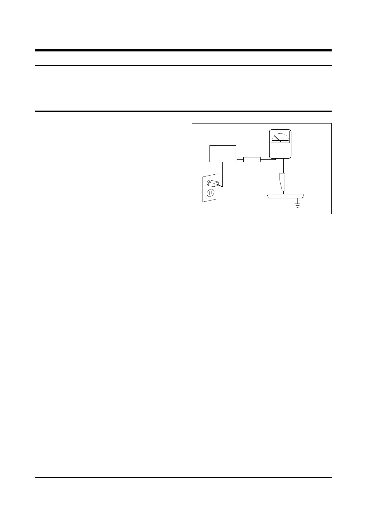
4. Leakage Current Hot Check (Figure 1-1):
Warning: Do not use an isolation
transformer during this test. Use a leakagecurrent tester or a metering system that
complies with American National Standards
Institute (ANIS C101.1, Leakage Current for
Appliances), and Underwriters Laboratories
(UL Publication UL1410, 59.7).
5. With the unit completely reassembled, plug
the AC line cord directly into the power
outlet. With the unit’s AC switch first in the
ON position and then OFF, measure the
current between a known earth ground (metal
water pipe, conduit, etc.) and all exposed
metal parts, including: antennas, handle
brackets, metal cabinets, screwheads and
control shafts. The current measured should
not exceed 0.5 milliamp. Reverse the powerplug prongs in the AC outlet and repeat the
test.
Fig. 1-1 AC Leakage Test
6. Antenna Cold Check:
With the unit’s AC plug disconnected from the
AC source, connect an electrical jumper across
the two AC prongs. Connect one lead of the
ohmmeter to an AC prong. Connect the other
lead to the coaxial connector.
7. X-ray Limits:
The picture tube is especially designed to prohibit X-ray emissions. To ensure continued
X-ray protection, replace the picture tube only
with one that is the same type as the original.
Carefully reinstall the picture tube shields and
mounting hardware; these also provide X-ray
protection.
8. High Voltage Limits:
High voltage must be measured each time servicing is done on the B+, horizontal deflection
or high voltage circuits. Correct operation of
the X-ray protection circuits must be
reconfirmed whenever they are serviced.
(X-ray protection circuits also may be called
“horizontal disable” or “hold-down”.)
Heed the high voltage limits. These include
the X–ray Protection Specifications Label, and
the Product Safety and X-ray Warning Note on
the service data schematic.
Precautions
Samsung Electronics 1-1
LEAKAGE
CURRENT
TESTER
DEVICE
UNDER
TEST
TEST ALL
EXPOSED METAL
SURFACES
2-WIRE CORD
ALSO TEST WITH
PLUG REVERSED
(USING AC ADAPTER
PLUG AS REQUIRED)
EARTH
GROUND
(READING SHOULD
NOT BE ABOVE
0.5mA)
Follow these safety, servicing and ESD precautions to prevent damage and protect against potential
hazards such as electrical shock and X-rays.
Page 4

1-1 Safety Precautions (Continued)
9. High voltage is maintained within specified
limits by close-tolerance, safety-related
components and adjustments. If the high
voltage exceeds the specified limits, check
each of the special components.
10. Design Alteration Warning:
Never alter or add to the mechanical or
electrical design of this unit. Example: Do not
add auxiliary audio or video connectors. Such
alterations might create a safety hazard. Also,
any design changes or additions will void the
manufacturer’s warranty.
11. Hot Chassis Warning:
Some TV receiver chassis are electrically
connected directly to one conductor of the AC
power cord. If an isolation transformer is not
used, these units may be safely serviced only
if the AC power plug is inserted so that the
chassis is connected to the ground side of the
AC source.
To confirm that the AC power plug is inserted
correctly, do the following: Using an AC
voltmeter, measure the voltage between the
chassis and a known earth ground. If the
reading is greater than 1.0V, remove the AC
power plug, reverse its polarity and reinsert.
Re-measure the voltage between the chassis
and ground.
12. Some TV chassis are designed to operate with
85 volts AC between chassis and ground,
regardless of the AC plug polarity. These units
can be safely serviced only if an isolation
transformer inserted between the receiver and
the power source.
13. Some TV chassis have a secondary ground
system in addition to the main chassis ground.
This secondary ground system is not
isolated from the AC power line. The two
ground systems are electrically separated by
insulating material that must not be defeated
or altered.
14. Components, parts and wiring that appear to
have overheated or that are otherwise
damaged should be replaced with parts that
meet the original specifications. Always
determine the cause of damage or overheating, and correct any potential hazards.
15. Observe the original lead dress, especially
near the following areas: Antenna wiring,
sharp edges, and especially the AC and high
voltage power supplies. Always inspect for
pinched, out-of-place, or frayed wiring. Do
not change the spacing between components
and the printed circuit board. Check the AC
power cord for damage. Make sure that leads
and components do not touch thermally hot
parts.
16. Picture Tube Implosion Warning:
The picture tube in this receiver employs
“integral implosion” protection. To ensure
continued implosion protection, make sure
that the replacement picture tube is the same
as the original.
17. Do not remove, install or handle the picture
tube without first putting on shatterproof
goggles equipped with side shields. Never
handle the picture tube by its neck. Some
“in-line” picture tubes are equipped with a
permanently attached deflection yoke; do not
try to remove such “permanently attached”
yokes from the picture tube.
18. Product Safety Notice:
Some electrical and mechanical parts have
special safety-related characteristics which
might not be obvious from visual inspection.
These safety features and the protection they
give might be lost if the replacement component differs from the original—even if the
replacement is rated for higher voltage,
wattage, etc.
Components that are critical for safety are
indicated in the circuit diagram by shading,
( ) or ( ).
Use replacement components that have the
same ratings, especially for flame resistance
and dielectric strength specifications.
A replacement part that does not have the
same safety characteristics as the original
might create shock, fire or other hazards.
Precautions
1-2 Samsung Electronics
Page 5

1-2 Servicing Precautions
1. Servicing precautions are printed on the
cabinet. Follow them.
2. Always unplug the unit’s AC power cord from
the AC power source before attempting to: (a)
Remove or reinstall any component or
assembly, (b) Disconnect an electrical plug or
connector, (c) Connect a test component in
parallel with an electrolytic capacitor.
3. Some components are raised above the printed
circuit board for safety. An insulation tube or
tape is sometimes used. The internal wiring is
sometimes clamped to prevent contact with
thermally hot components. Reinstall all such
elements to their original position.
4. After servicing, always check that the screws,
components and wiring have been correctly
reinstalled. Make sure that the portion around
the serviced part has not been damaged.
5. Check the insulation between the blades of the
AC plug and accessible conductive parts
(examples: metal panels, input terminals and
earphone jacks).
6. Insulation Checking Procedure: Disconnect the
power cord from the AC source and turn the
power switch ON. Connect an insulation
resistance meter (500V) to the blades of the AC
plug.
The insulation resistance between each blade
of the AC plug and accessible conductive parts
(see above) should be greater than 1 megohm.
7. Never defeat any of the B+ voltage interlocks.
Do not apply AC power to the unit (or any of
its assemblies) unless all solid-state heat sinks
are correctly installed.
8. Always connect a test instrument’s ground
lead to the instrument chassis ground before
connecting the positive lead; always remove
the instrument’s ground lead last.
9. When some parts inside the optical engine
(except lamp) are damaged, replace the whole
optical engine.
Precautions
Samsung Electronics 1-3
Warning 1 : First read the “Safety Precautions” section of this manual. If some unforeseen circumstance creates a
conflict between the servicing and safety precautions, always follow the safety precautions.
Warning 2 : An electrolytic capacitor installed with the wrong polarity might explode.
“CAUTION : Double-pole/neutral fusing”
Page 6

1-3 Precautions for Electrostatically Sensitive Devices (ESDs)
1. Some semiconductor (“solid state”) devices
are easily damaged by static electricity. Such
components are called Electrostatically
Sensitive Devices (ESDs); examples include
integrated circuits and some field-effect
transistors. The following techniques will
reduce the occurrence of component damage
caused by static electricity.
2. Immediately before handling any semicon
ductor components or assemblies, drain the
electrostatic charge from your body by
touching a known earth ground. Alternatively,
wear a discharging wrist-strap device. (Be
sure to remove it prior to applying power—
this is an electric shock precaution.)
3. After removing an ESD-equipped assembly,
place it on a conductive surface such as
aluminum foil to prevent accumulation of
electrostatic charge.
4. Do not use freon-propelled chemicals. These
can generate electrical charges that damage
ESDs.
5. Use only a grounded-tip soldering iron when
soldering or unsoldering ESDs.
6. Use only an anti-static solder removal device.
Many solder removal devices are not rated as
“anti-static”; these can accumulate sufficient
electrical charge to damage ESDs.
7. Do not remove a replacement ESD from its
protective package until you are ready to
install it. Most replacement ESDs are
packaged with leads that are electrically
shorted together by conductive foam,
aluminum foil or other conductive materials.
8. Immediately before removing the protective
material from the leads of a replacement ESD,
touch the protective material to the chassis or
circuit assembly into which the device will be
installed.
9. Minimize body motions when handling
unpackaged replacement ESDs. Motions such
as brushing clothes together, or lifting a foot
from a carpeted floor can generate enough
static electricity to damage an ESD.
Precautions
1-4 Samsung Electronics
CAUTION
These servicing instructions are for use by
qualified service personnel only.
To reduce the risk of electric shock do not
perform any servicing other than that contained
in the operating instructions unless you are
qualified to do so.
Page 7

Troubleshooting
Samsung Electronics 5-1
5. Troubleshooting
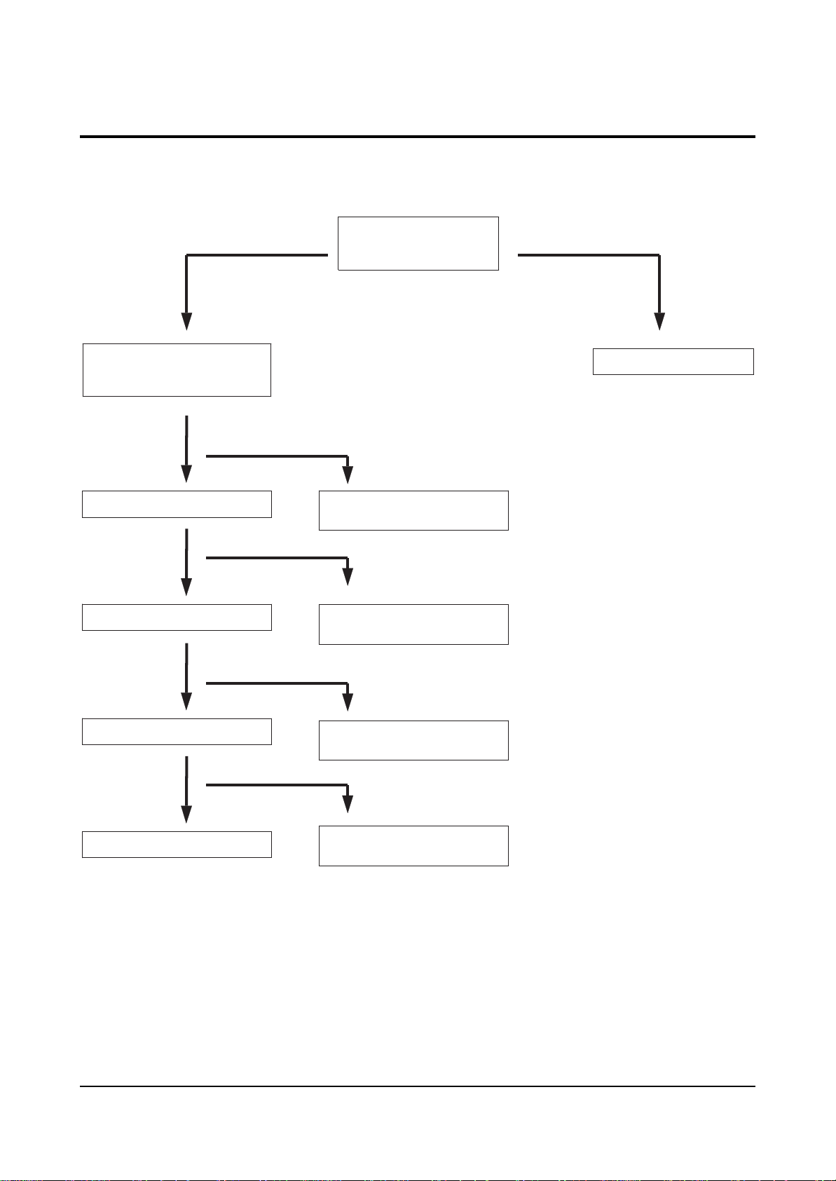
5-1 Convergence Misaligned
Check the voltage of CNZ03
on the CG-AMP board and
the waveform of CNZ01
Nomal
Check FD101S,FD102S
on the CG-AMP board
Nomal
Check the input/output
of ICZ103,ICZ104
on the CG-AMP board
Abnomal
Abnomal
Nomal
Check the input
voltage of main
CNZ02 and sub CN803
Check connectors
MAIN ↔ CG-AMP
SUB ↔ CG-AMP
Replace FD101S,FD102S
and check associate circuits
Abnomal
Check the output from
CG-MDL and FD855S,
FD802S on the SUB PCB
Nomal
Check the output from
CNZ02,CNZ04,CNZ05
on the CG-AMP board
Nomal
Check DY
Abnomal
Check the circuits
related to ICZ103,ICZ104
Abnomal
Check the circuits related to
CNZ02,CNZ04,CNZ05
Page 8
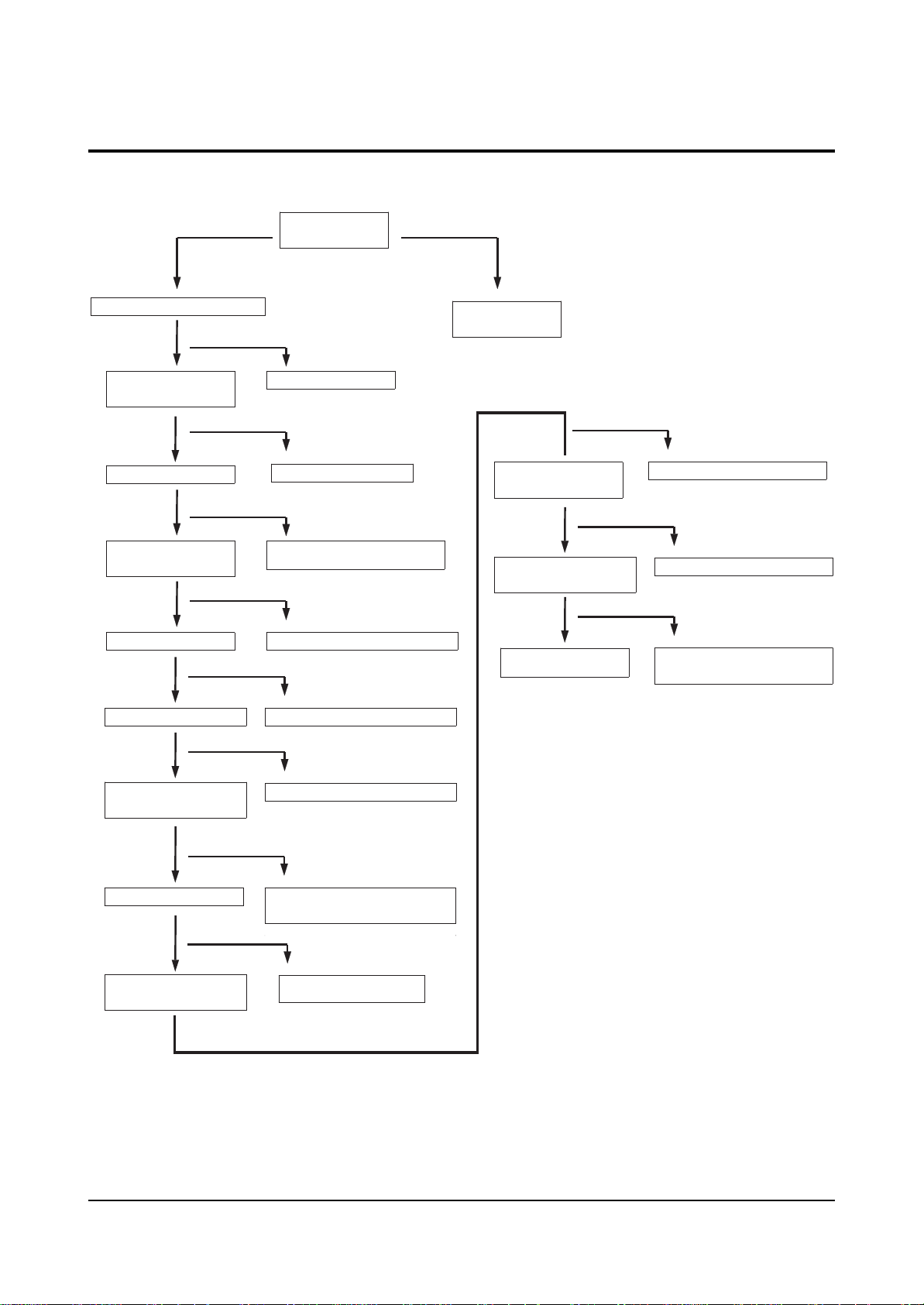
5-2 No Sound
Troubleshooting
5-2 Samsung Electronics
Check the input/output
circuits of IC601
Nomal
Check ICD603
Nomal
Check IC602
Abnomal
Abnomal
Abnomal
Check the output
volume level of
MAIN CN601
Check the circuits
related to IC601
Check the circuits
related to IC601
Nomal
Check SPEAKER
Nomal
Check IC605
Nomal
Check various input circuits
Abnomal
Check the circuits
related to IC602
Abnomal
Check the circuits
related to IC605
Page 9
Troubleshooting
Samsung Electronics 5-3
5-3 No Raster
Check the operating
status of remote control
and POWER S/W
Check the input voltage of PWE CORD
Check the Standby
voltage of ICS802
Check MICOM VCC
Check the operating status
of MICOM POWER PORT
Check QS802
Check ICS801,PC811S
Check the input voltage
Check IC831,PC801S
Check the circuits related to
MICOM VCC input
Check the circuits related to IR / MICOM
Check the circuits related to QS802
Check the remote
control and
CONTROL ASSY
Check the input
voltage/waveform of
CRT-PCB CN501,CN504
Check the input/output
circuits of IC501,IC531,IC561
Check the voltage
of CRT,SCREEN
Check the circuits inside D/W-MDL
Check CONNECTOR WIRE
Check the circuits related to
the input/output of IC501,IC531,IC561
Check the voltage/waveform
of CN801,CN802,CN401
Check the input of D/W-MDL
Check the output from
D/W-MDL CN03
Check the circuits related to ICS801,PC811S
Check the circuits related to
CN801,CN802,CN401
Check the circuits related to
D/W-MDL input
Page 10

MEMO
5-4 Samsung Electronics
Page 11

Specifications
Samsung Electronics 3-1
3. Specifications
Broadcasting System
Scanning System
Tuning Range
Antenna Impedance
Intermediate Frequency
Sound Output
Rated Voltage
W/B Coordinates
High Voltage
FUSE
Power Consumption
Dimension
Weight
NTSC
Progressive Scanning
VHF : CH2 ~ CH13
75 ohm Unbalanced
Video : 45.75 MHz
Sound : 42.25 MHz
Chrominance Subcarrier : 42.17 MHz
STD : 10W
MAX : 15W
120V / 60 Hz
Hx : 266 Hy : 280 Y : 8.9
Lx : 268 Ly : 283 Y : 0.38
29KV
250V/6.3A
CODE NO : 3601-000300
240W
1002 X 450 X 1070mm
39.4 X 17.7 X 42.1 inch
49Kg 108lbs
Page 12

MEMO
3-2 Samsung Electronics
Page 13
Alignment and Adjustments
Samsung Electronics 4-1
4. Alignment and Adjustments
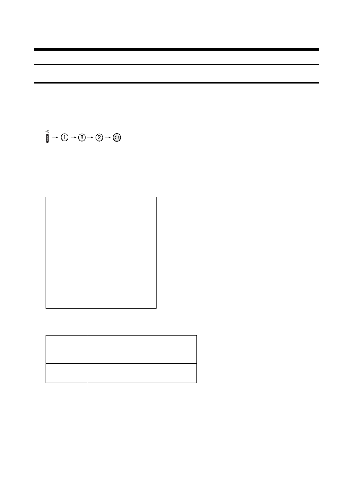
4-1 When entering the service mode:
1. Turn on the TV, and then select “STANDARD”on the picture adjustment mode.
2. Turn off the TV (STAND-BY).
3. Enter the service mode by pressing the remote control keys in the following sequence :
Note : If necessary, re-do steps 1~3.
Initial display when the service mode is switched.
SERVICE / Sim-474A
DEFLECTION
480P OFFSET
1080i OFFSET
CONVERGENCE OFFSET
VIDEO ADJUST 1
VIDEO ADJUST 2
VIDEO ADJUST 3
VIDEO ADJUST 4
OPTION (E3h 98h 0ch)
RESET / 02-05-03
1. When a RF signal is received
MAIN MENU MENU DISPLAY
CH UP/DOWN Select item by moving cursor
VOL UP/DOWN Decrease or increase the adjustment values
3. Service Mode Control Keys
< PRECAUTIONS >
1. When EEPROM IC (IC902) is replaced, first connect the power cord and wait for about 4~5 seconds.
2. After replacing EEPROM IC (IC902), enter the Service mode. Next, enter the standard data or the
previous EEPROM IC data before replacement. And then check and adjust any items related to
Geometric, Picture, Option.
Page 14

Alignment and Adjustments
4-2 Samsung Electronics
4-2-1 Defection
4-2 Factory Data
☞ DVI connection item is corresponded to DVI application model.
ITEM INITIAL DATA
V Amp
V Shift
H EW
H Shift
V Linearity
Upper Linearity
Lower Linearity
VSC
H Parabola
Upper Corner
Lower Corner
H Trapezium
Bow
Range
0 ~ 63
32
32
6 fix
7
8
3
10
32
32
32
32
0 ~ 63
0 ~ 63
0 ~ 63
0 ~ 15
0 ~ 15
0 ~ 15
0 ~ 15
0 ~ 63
0 ~ 63
0 ~ 63
0 ~ 63
0 ~ 63
EEP-ROM Copy Data
RF
31
29
31
31
7
0
0
7
31
31
31
31
31
480P
-
-
-
-
-
-
-
-
-
-
-
-
-
1080i
-
-
-
-
-
-
-
-
-
-
-
-
-
Remark
variable
variable
fix
fix
fix
fix
fix
fix
fix
fix
fix
fix
Angel
V Position
CXA Left Blk
CXA Right Blk
32
32
35
35
0 ~ 63
0 ~ 63
0 ~ 63
0 ~ 63
31
31
35
35
-
-
-
-
-
-
-
-
fix
fix
fix
fix
Page 15

Alignment and Adjustments
Samsung Electronics 4-3
4-2-2 480P Offset
ITEM INITIAL DATA
V Amp
V Shift
H EW
H Shift
V Linearity
Upper Linearity
Lower Linearity
VSC
H Parabola
Upper Corner
Lower Corner
H Trapezium
Bow
Range
0
0
0
0
0
0
0
0
0
0
0
0
0
-63 ~ 63
-63 ~ 63
-63 ~ 63
-63 ~ 63
-15~ 15
-15~ 15
-15~ 15
-15~ 15
-63 ~ 63
-63 ~ 63
-63 ~ 63
-63 ~ 63
-63 ~ 63
EEP-ROM Copy Data
RF 480P
-
-
-
-
-
-
-
-
-
-
-
-
-
0
0
0
0
0
0
0
0
0
0
0
0
0
1080i
-
-
-
-
-
-
-
-
-
-
-
-
-
Remark
variable
variable
variable
variable
fix
fix
fix
fix
fix
fix
fix
fix
fix
Angel
V Position
CXA Left Blk
CXA Right Blk
0
0
-63 ~ 63
-63 ~ 63
-63 ~ 63
-63 ~ 63
-
-
-
-
0
0
28
36
-
-
-
-
fix
fix
fix
fix
Page 16
Alignment and Adjustments
4-4 Samsung Electronics
4-2-3 1080i Offset
ITEM INITIAL DATA
V Amp 0
V Shift 0
H EW 0
H Shift 0
V Linearity 0
Upper Linearity 0
Lower Linearity 0
VSC 0
H Parabola 0
Upper Corner 0
Lower Corner 0
H Trapezium 0
Bow 0
0
0
0
0
0
0
0
0
0
0
0
0
0
Range
-63 ~ 63
-63 ~ 63
-63 ~ 63
-63 ~ 63
-15~ 15
-15~ 15
-15~ 15
-15~ 15
-63 ~ 63
-63 ~ 63
-63 ~ 63
-63 ~ 63
-63 ~ 63
EEP-ROM Copy Data
RF 480P
-
-
-
-
-
-
-
-
-
-
-
-
-
-
-
-
-
-
-
-
-
-
-
-
-
-
1080i
Remark
variable
variable
variable
fix
Angel 0
V Position 0
0
0
CXA Left Blk
CXA Right Blk
-63 ~ 63
-63 ~ 63
-63 ~ 63
-63 ~ 63
-
-
-
-
-
-
-
-
63
20
Page 17

Alignment and Adjustments
Samsung Electronics 4-5
4-2-4 CONVERGRNCE OFFSET
ITEM INITIAL DATA
Offset Enable
V Amp
V Shift
H EW
V Amp 1080i
V Shift 1080i
H EW 1080i
Range
0 variable
15
0
15
15
0
15
0 ~ 1
-63 ~ 63
-63 ~ 63
-63 ~ 63
-63 ~ 63
-63 ~ 63
-63 ~ 63
EEP-ROM Copy Data
RF 480P
0
15
0
15
15
0
15
Remark
1080i
variable
variable
variable
variable
variable
variable
Page 18
Alignment and Adjustments
4-6 Samsung Electronics
4-2-5 VIDEO ADJUST 1
ITEM INITIAL DATA
R Cutoff 20
G Cutoff 20
B Cutoff 20
Color On/Off 1
CR offset 32 fix
CB offset 32
R Driver 31
G Driver 31
B Driver 31
Sub Bright 15
Sub Contrast 7
Sub Color 20
SubTint 7
Range
0 ~ 63
0 ~ 63
0 ~ 63
0 ~ 1
0 ~ 15
0 ~ 15
0 ~ 15
0 ~ 15
0 ~ 63
0 ~ 63
0 ~ 15
0 ~ 23
0 ~ 13
EEP-ROM Copy Data
RF-Copy
31
31
31
W/B
Control Value
20
20
20
1
32
32
20
20
20
31
31
31
15
7
20
8(AV/SV/DVD/480P)
1080i
31
31
31
20
20
20
10
Remark
variable
variable
fix
fix
variable
fix
variable
variable
variable
fix
CTI Level 1
CDL AXIS 2
LTI Level 0
0 ~ 3
0 ~ 3
0 ~ 3
1 (RF/AV/SV/DVD/480P/1080i)
2
1(RF/AV/SV/DVD/480P)
fix
fix
2
fix
Page 19
Alignment and Adjustments
Samsung Electronics 4-7
4-2-6 VIDEO ADJUST 2
ITEM INITIAL DATA
ABL Mode 3
Gamma 2
DPIC Level 3
DC Trans 3
ABL TH 15
VM Level 2
VM Coring 0
VM f0 0
VM Limit 0
VM Delay 0
SHP CD 1
SHP f0 0
SHP f1 & P/O 11
Range
0 ~ 3
0 ~ 3
0 ~ 3
0 ~ 3
0 ~ 15
0 ~ 3
0 ~ 3
0 ~ 3
0 ~ 3
0 ~ 3
0 ~ 3
0 ~ 1
0 ~ 15
EEP-ROM Copy Data
RF 480P
3
1
3
1
15
2
0
2 (RF/AV/SV/DVD/480P)
0
0 (RF/AV/DVD)
1 (480P)
1
0
1 (AV/SV/DVD/Comp2)
13 1 (RF/AV/SVHS/DVD/Comp2)
1080i
1
Remark
fix
fix
fix
fix
fix
fix
fix
fix
fix
fix
AKB Time 13
Y/C Delay 30
PIP Y/C Delay 30
BAND PASS F 1
HIGH PASS F 3
0 ~ 31
0 ~ 31
0 ~ 31
0 ~ 7
0 ~ 7
16
30
30
1
3
Page 20
Alignment and Adjustments
4-8 Samsung Electronics
4-2-7 VIDEO ADJUST 3
ITEM INITIAL DATA
VSU 2
Melody Volume 4
H Comp 0
V Comp 0
Pin Comp 0
AFC Comp 0
Sync Comp 0
NR Off Value 5
V-Mute(x100ns)
Range
0 ~ 15
0 ~ 20
0 ~ 15
0 ~ 15
0 ~ 15
0 ~ 7
0 ~ 1
0 ~ 9
8
0 ~ 10
EEP-ROM Copy Data
RF 480P
2
4
0
0
0
0
0
5
8
-
-
-
-
-
-
-
-
-
Remark
1080i
-
-
-
-
-
-
-
-
-
Page 21

Alignment and Adjustments
Samsung Electronics 4-9
4-2-8 VIDEO ADJUST 4
ITEM INITIAL DATA
System RF 1
System_VSD_480P 1
System_1080i 2
Shp_Fo_VSD_480P 1
HPF_VSD 3
BPF_VSD 1
Chrm_bdwth_RF 28
Chrm_bdwth_Video 28
Chrm_bdwth_Svideo 30
Chrm_bdwth_DVD 28
IF_Comp_RF 2
IF_Comp_Video 4
IF_Comp_Svideo 5
Range
0 ~ 3
0 ~ 3
0 ~ 3
0 ~ 1
0 ~ 7
0 ~ 7
0 ~ 63
0 ~ 63
0 ~ 63
0 ~ 63
0 ~ 7
0 ~ 7
0 ~ 7
EEP-ROM Copy Data
RF 480P
1
1
1
3
1
3 (AVS/SV/DVD)
1 (AVS/SV/DVD)
28
28
30
28
2
4
5
1080i
2
Remark
fix
fix
fix
fix
fix
fix
fix
fix
fix
IF_Comp_DVD 4
VM_Delay_480P 1
0 ~ 7
0 ~ 3
4
1
fix
fix
Page 22

Alignment and Adjustments
4-10 Samsung Electronics
4-2-9 OPTION
ITEM INITIAL DATA
CRT WIDE
PIP ON
3D-Comb Filter OFF
Blue Screen
OFF
BBE Effect
Auto power On
System CT
Virtual Dolby
OFF
ACS
V chip (CT,CTA)
V chop Area USA
Sub Woofer
OFF
No Sync Mute
DVI
AGC
Tubo Effect
Burst Screen
DW Multi
OFF
OFF
OFF
Large
Letter Box
ON
ON
ON
ON
ON
ON
ON
Range
WIDE ↔ 4:3
ON ↔ OFF
ON ↔ OFF
ON ↔ OFF
ON ↔ OFF
ON ↔ OFF
CT (EN+SP+ER)→CT-A(E+SP+F)
ON ↔ OFF
ON ↔ OFF
ON ↔ OFF
USA
ON ↔ OFF
ON ↔ OFF
ON ↔ OFF
ON ↔ OFF
ON ↔ OFF
ON ↔ OFF
Large ↔ Double
ON ↔ OFF
HCM4216W,HCM4215W,
HCL4715WB,HCM4715W
(PCL5415RB,PCM5415R)
HCM5525WB,PTH5598W
WIDE(4:3)
ON
OFF
ON
ON
ON
CT
OFF
ON
ON
USA
OFF
ON
OFF
OFF
OFF
OFF
Large
ON
HCM422W,HCM473WB
(PCL545RB,PCM545R)
HCM553WB
WIDE(4:3)
ON
ON
ON
ON
ON
CT
OFF
ON
ON
USA
OFF
ON
OFF
OFF
OFF
OFF
Double
ON
Page 23
Alignment and Adjustments
Samsung Electronics 4-11
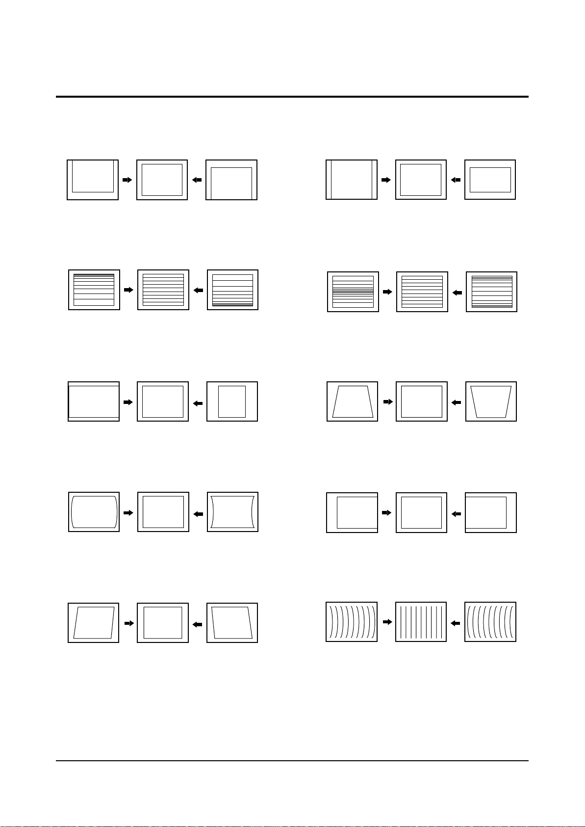
4-3 Screen Change (When adjusting I2C Bus Geometric items)
1 V SHIFT
2 V LINEARITY
3 H SIZE
6 V SIZE
7 V - S - CORRECTION
8
PIN PHASE
4
PIN AMP
5 V ANGLE
9 H SHIFT
10 V BOW
Page 24
Alignment and Adjustments
4-12 Samsung Electronics
4-4 Other Adjustments
4-4-1 Screen Adjustment
1. Warm up the TV for at least 30 minutes.
2. Select the “ STANDARD” Video mode.
3. Turn to the Video Mode (No Signal) using a
remote-control.
4. Connect an oscilloscope to RK,GK,BK.
5. Adjust the VR (VR501, VR531, VR561) screen
so that RK, GK, BK pulse is 20Vp-p each.
(Turn the R,G,B VR screen fully
counterclockwise in the area of each flyback
line.)
4-4-2 White Balance Adjustment
1. Select the “STANDARD” video mode.
2. Input 100% white pattern.
3. In the stand-by mode, press the remote-control
keys in the following sequence:
4. Warm up the TV for at least 30 minutes.
5. Input a 10-step signal.
6. R-cut off, B-cut off, and G-cut off by pressing
the Volume keys.
7. Adjust the low light with viewing the dark
side of the screen.
8. Select R-drive, G-drive, and B-drive by
pressing the Volume keys.
9. Adjust the high light with viewing the light
side of the screen.
10. If necessary, redo adjustments 6~9.
11. Press the Menu key to exit.
4-4-3 Sub-Brightness Adjustment
1. Input a sub-brightness adjustment signal.
(TOSHIBA PATTERN)
2. In the stand-by mode, press the remote-control
keys in the following sequence :
3. Select SBT by pressing the Volume keys.
4. Adjust so that the 63 step on the right side of
the screen is not seen (Use the Volume
keys).
5. Press the Menu key to exit.
4-4-4 High Voltage (29KV) Check
PRECAUTION
1. Input a lion head pattern.
2. Select “STANDARD” video mode.
3. Warm up the TV for at least 10 minutes.
4. Use a 1000:1 probe.
ADJUSTMENT
1. Connect the (+) terminal of the 1000:1 probe to
the high voltage distributor and the (-)
terminal to GND (located on the deflection
board).
2. Adjust RR471S (located on the deflection
board) so that the digital meter indicates
DC 29V ± 0.1V.
4-4-5 F.S. (Fail Safe) Adjustment
Note : The finished product has a well-mounted
VR (RR402S).
If necessary, do the F.S. adjustments in the
following sequence.
1. Use a digital multimeter.
2. Connect the digital multimeter to the JIG pin
(DZ482S) terminals
3. Adjust VR (RR402S) so that the voltage
becomes 2.25V.
4. After the adjustments are complete, be sure to
mount VR (RR402S) correctly.
Page 25

Alignment and Adjustments
Samsung Electronics 4-13
4-4-6 F.S. (Fail Safe) Circuit Check
Note : The F.S. Circuit check must be performed
after servicing.
1. Turn on the TV.
2. Select the “STANDARD” video mode.
3. Short F/S Test point (located on the SUB PCB).
Then, both sound and picture disappear.
(Note: Even if the shorted terminals are
removed, both sound and
picture do not appear. This proves the F.S.
circuit is working. )
4. To restore both sound and picture, turn off the
TV and reset it after about 30 seconds.
4-4-7 Static Focus Adjustment
PRECAUTION
1. Select the “STANDARD” video mode.
2. Input a crosshatch pattern.
3. Cover the lenses that are not being adjusted.
4. Connect a convergence jig and read data.
5. Adjust the lens for best focus.
(See Fig, 4-1)
STATIC FOCUS (CONTINUED)
Vary the focus pack VR (Red, Blue) on the
front cabinet. Adjust the TV for best possible
focus around the center of the crosshatch
pattern, without losing overall screen balance.
Figure Crosshatch Pattern
Examine these points together.
4-4-8 Lens Focus Adjustment
PRECAUTIONS
1. Do this adjustment after the static focus
adjustment and the tilt adjustment.
2. Select the “STANDARD” video mode.
(Contrast:100, Brightness:50)
3. Input a crosshatch pattern.
ADJUSTMENT
1. Loosen the lens screws.
2. Cover the two lenses that are not being
adjusted.
3. Adjust the lens, observing the color aberration
vertically and horizontally within 3 blocks of
the center of the crosshatch pattern.
4. When the lens is turned clockwise, the color
aberration will change as follows:
Lens Color Aberration Change
R Orange - Crimson
G Blue - Red
B Purple - Green
5. Green lens adjustment:
Set the lens at the point where Blue just
changes to Red. If the color aberration is
irregular throughout the picture screen, adjust
the lens to show Red color aberration
(approximately 1~3 mm area) within a 3-block
grid around the horizontal center-line. If the
color aberration is irregular, adjust the lens as
shown in the diagram below. (Accurate
alignment of Green is important for overall
color quality.)
6. Red lens adjustment
Set the Red lens at the point where Orange
becomes Crimson.
7. Blue lens adjustment
Set the Blue lens at the point where Purple
becomes Green.
P
L1
L2
RED ABERRATION
BLUE ABERRATION
L1, L2 < P
_
Fig. 4-1 Crosshatch Pattern.
Fig. 4-2 Color Aberration
Examine these points together
Page 26
Alignment and Adjustments
4-14 Samsung Electronics
1. Select the “STANDARD” video mode.
2. Warm up the set at least for 10 minutes.
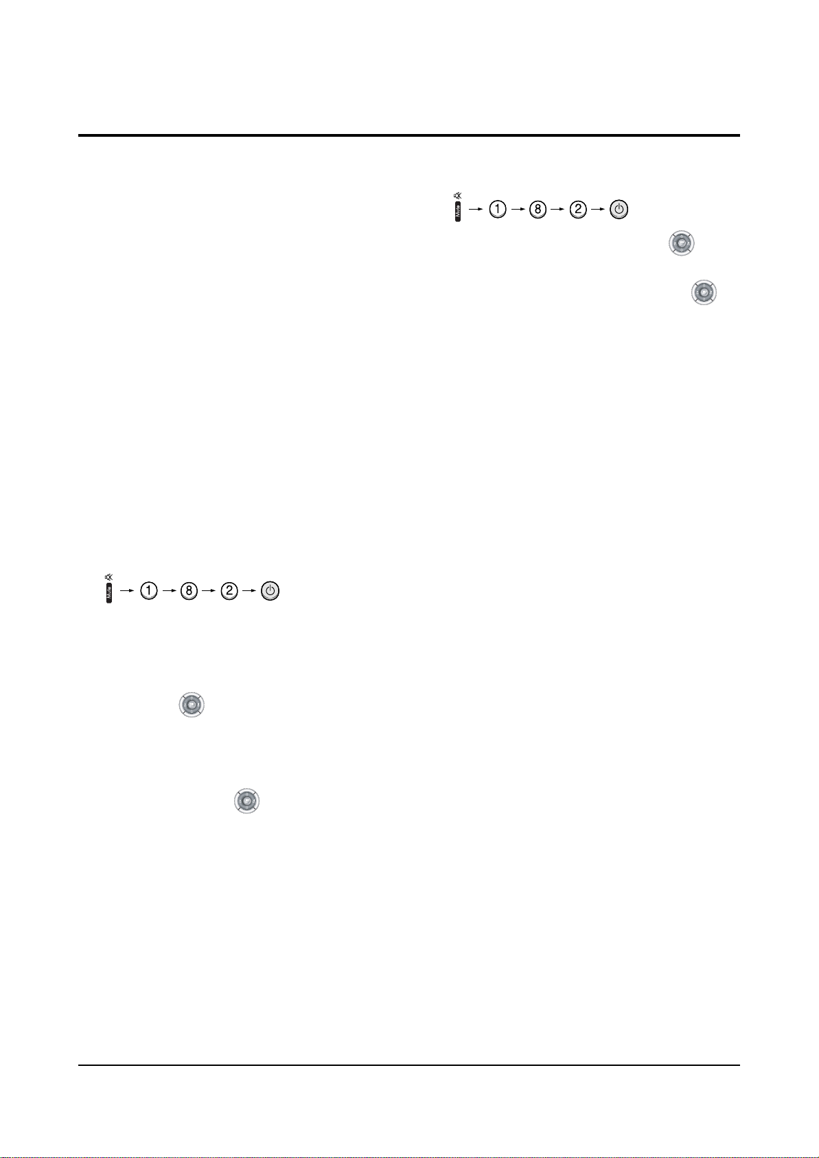
3. Enter the Convergence mode by pressing the remote control buttons in the following sequence
:
4. Set the Beam Alignment Adjustment CY to Zero magnetic field area.
5. Check the squarewave at the point where the focus is misaligned (Use an audio oscillator).
6. Press the button on the remote control, and a vibrating dot-pattern appears.
7. Adjust the Focus-pack VR for defocusing.
8. Mute the other patterns (R/B) other than G-PATTERN.
(Use / buttons on the remote control.)
9. Adjust the 2, 4 polarities of VM-COIL as shown in figure below.
10. Adjust the G-Focus until any light around the core disappears.
11. Adjust G-Focus so that the surrounding flash can disappear from the spot.
12. After G-Focus adjustments are complete, adjust R-Focus as above procedures.
13. The B-CRT adjustments can be omitted because the variance of beam focus is small.
(Only Vm-coil is mounted.)
14. Adjust the Focus-pack VR for fine focusing.
15. Press the button on the remote control, and the mode changes to the Convergence Adjustment
mode.
16. Press the button on the remote control to return to normal viewing.
4-5 Beam alignment Adjustments
(Creation of CPM Zero Magnet)
(Creation of the 2-pole/4-pole zero magnets)
G-FOCUS
(Varying G-Focus Pack)
G-FOCUS
(When VM 2-Pole Adjustment is completed)
CORE
CORE
Varying the 2-pole of VM
Varying the 4-pole of VM
(Positioning the Core in the Center)
(Adjust until the light around
the core becomes a circle)
Page 27
Alignment and Adjustments
Samsung Electronics 4-15
4-6 Hige Voltage Part
4-6-1 PWM REG Circuit
For the existing high voltage REG circuit (input
voltage variation type), a dynamic REG response
is not provided. So it is difficult for both beam
linearity and uniformity in screen size to be
maintained on the screen with rapidly changing
beams.
A PWM (Pulse Width Modulation) type of high
voltage, however, provides the maintenance of
beam linearity and uniformity in screen size via a
quick response to beam change by performing
sync lock every 1H line, and detecting beam
fluctuation at 1H line, and then controlling the IC
current of high voltage output circuit.
1. High Voltage Fluctuation Detect (DC Detect)
FBT pin 11 detects DC high voltage fluctuation.
The detected DC high voltage value is input to
PWM IC471 pin1 through R473, VR471, R471,
and then it is input to a differential AMP circuit
that differentiates the gap after comparing with
the reference voltage input to pin2.
2. High Voltage Fluctuation Detect (AC Detect)
To check AC high voltage fluctuation, the
output from FBT is detected by using a
capacitor inside the high voltage distributor. The
detection of AC high voltage fluctuation,
a detection of dynamic beam current change is
required in order to keep beam linearity and
uniformity in size.
Regarding the capacitor, a capacity of less than
3000P should be applied to a PWM type. (The
existing type needs a capacity of about 6000P.)
AC detect circuit eliminates unnecessary high
frequency by using C476, D472. Also, AC gain is
limited to + / - 0.7V (D472). This AC gain is
combined with the detection value of DC high
voltage fluctuation by using C478.
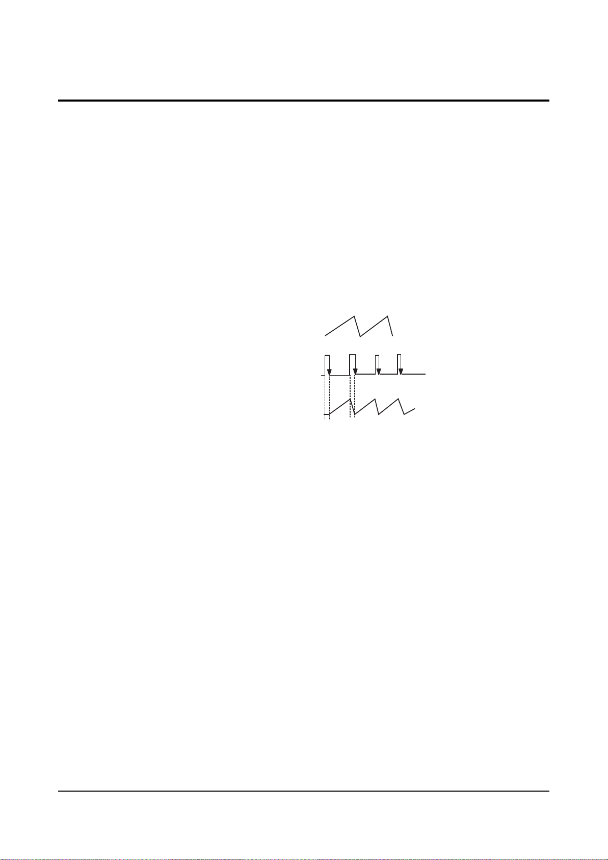
3. PWM IC OSC Sync Lock
A PWM type IC needs sync lock for PWM pulse
and horizontal scan line.
The standard time constant of OSC circuit is
determined by C487, R475 (PWM IC pins 5 and 6).
And the standard OSC frequency is about 27
kHz . The horizontal frequency of scan line is
31.5kHz(NT), 3375kHz(DTV), 15.75kHz(Interface),
so sync lock for this horizontal frequency should
be performed using sync lock circuit. The sync
lock circuit consists of Q481(Tr KSC815-Y),
D479, D478, and C492. The input AFC signal is
connected to PWM IC pin 5 through D479 so
that it can be negative Trig.
4. Dead Time (HV Protect)
Dead Time (PWM IN pin4) consists of C481,
delays high voltage for a certain time to soft
start in power on, a x-ray protection circuit.
The voltage of Dead Time is detected by FBT
pin7 and through DC Feedback. The normal
voltage of Dead Time is +27V. When high
voltage increases, however, detected voltage is
in proportion to high voltage. Then, the detected
voltage is applied to ICR01S(TL431).
If the voltage is over 2.5V (normal:about 2.25V),
TL431 turns ON, the base port of QR401S
becomes low, and then an emitter current flows.
At this time, a high voltage protection point is
set. When QR401S turns ON, high voltage is
applied to PWM IC pin4 and then muted.
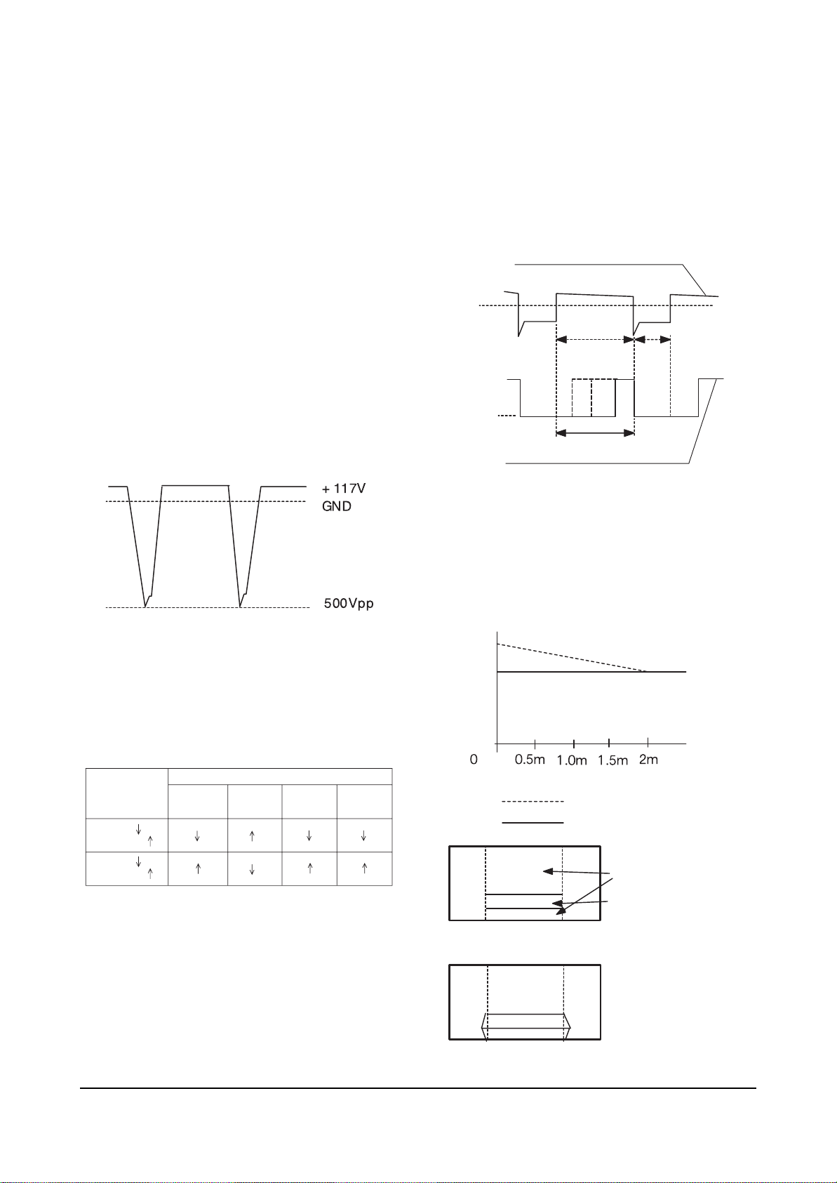
OSC : 27KHz
AFC Waveform : 31.5KHz(NT)
Locked OSC Waveform : 31.5KHz
Page 28
Alignment and Adjustments
4-16 Samsung Electronics
5. Output Circuit
The voltages, which are detected form an error
detection circuit of PWM IC (Differential AMP)
and Dead Time, each is applied to PWM
conparator . Due to these detection coltages, Q1,
Q2 (Output TR) parallel operate. Q482 (External
TR), however, functions as a buffer; natches
inpedance between the output port of PWM IC
and the final output TR(IRFS640). The PWM
pulse (applied to the final output FET (IRFS640
GATE) varies the IC current of high voltage
TR(Q473) by adjusting the load impedance of
starage Trans (T431). Due to this variation of
current, the gain for Q473 emitter pulse changes
T444(FBT)makes this emitter pulse became high
voltage. Such change keeps both dynamic and
static changes fixed. The output waveform of
high valtage TR emitter is as shown in the figure
below.
6. Paraneters according to beam
To maintain the set high voltage value (31kV),
parmaters such as +Ve (DC), Vcp High Voltage
change (See the table below).
7. Response Waveform
To reduce unstable high voltage fluctuation, the
existing high voltage type REG circuit controls
dynamic fluctuation by using C-block capacitor.
But, it can't detect actual dynamic fluctuation.
Also, its velocity of response to static fluctuation
is late because +B power supply changes per
about 1V. A PWM modulation type REG detects
static, dynamic high voltage fluctuation for only
Ton Time (when the current of the output TR
collector flows) each 1H, and modulates the
width of PWM pulse. So, this PWM type has
better improvement in the characteristic of high
voltage REG as compared to the existing type.
8. Application Effects
1) Improvement of horizontal size fluctuation
2) Linearity improved
3) Embodiment of X-ray protection circuit
The figures below show characteristics when a
PWM high voltage REG circuit is applied.
Beam
(High voltage )
Factor of high
voltage change
Beam
(High voltage )
Width of FET
Gate Pulse
+ Ve (DC)
Vcp
High
Voltage
Parameters
High Voltage Drive Base Current
PWM Input Waveform of FET GATE
GND
GND
PWM Variation tange
Ton Toff
Beam
High Voltage
High Voltage OFF
High Voltage REG ON
BLACK
WHITE
When a Toshiba Pattern
is recrived, the screen is
displayed as shown in
figute side
Existing type
PWM type
Page 29
Alignment and Adjustments
Samsung Electronics 4-17
4-7 Screen-Jig
4-7-1 HCM4215W/HCM422W/HCM4216W (NORMAL MODE)
4-7-2 HCM4215W/HCM422W/HCM4216W (DTV MODE)
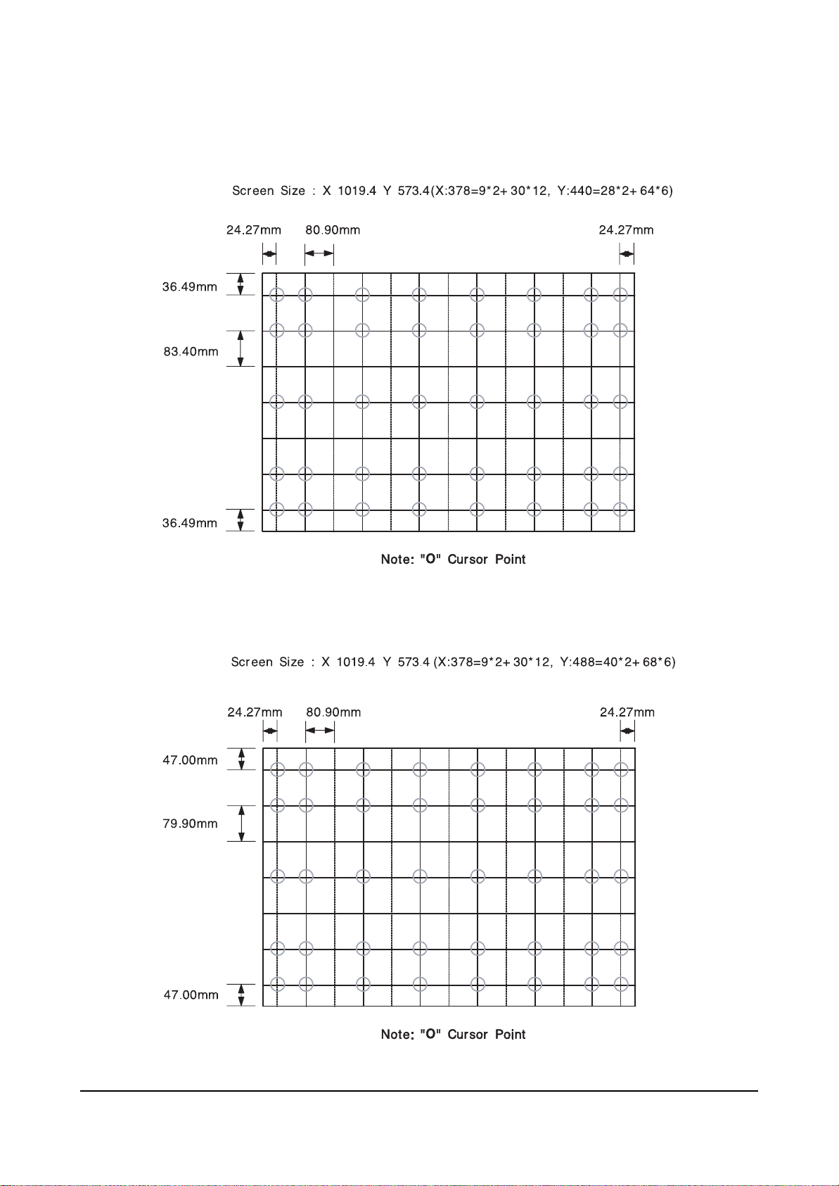
42W5ScreenSize:X932,Y524(X:378=9*2+30*12,Y:440=28*2+64*6)
22.19mm 73.97mm
33.35mm
76.22mm
42W5 TV
33.35mm
22.19mm
42W5 DTV Mode : X 932, Y 524 (X:408=18*2+31*12, Y:488=40*2+68*6)
41.12mm 70.81mm
42.95mm
73.02mm
42W5 DTV
42.95mm
41.12mm
Page 30
Alignment and Adjustments
4-18 Samsung Electronics
4-7-3 473W/4715W (NORMAL MODE)
4-7-4 473W/4715W (DTV MODE)
Page 31

Alignment and Adjustments
Samsung Electronics 4-19
4-7-5 5415R/545R/54J9 (NORMAL MODE)
4-7-6 5415R/545R/54J9 (DTV MODE)
Page 32

Alignment and Adjustments
4-20 Samsung Electronics
4-7-7 552W/5515W/5525W/553W/PTH5598 (NORMAL MODE)
4-7-8 552W/5515W/5525W/553W/PTH5598 (DTV MODE)
Page 33

Alignment and Adjustments
Samsung Electronics 4-21
4-7-9 6215R (NORMAL MODE)
4-7-10 6215R (DTV MODE)
Page 34

Alignment and Adjustments
4-22 Samsung Electronics
4-7-11 652W/653W/6515R (NORMAL MODE)
4-7-12 652W/653W/6515R (DTV MODE)
Page 35

Alignment and Adjustments
Samsung Electronics 4-23
4-8 Remote Control for Servicing (Convergence Mode)
Page 36

Alignment and Adjustments
4-24 Samsung Electronics
4-7-1 KEY Function
1. R-SELECT
Press to select RED color.
2. G-SELECT
Press to select GREEN color.
3. B-SELECT
Press to select BLUE color.
4. R-MUTE
Press to mute RED color.
5. G-MUTE
Press to mute GREEN color.
6. B-MUTE
Press to mute BLUE color.
7. CANCEL KEY
Press to revert to the previous data during the Convergence
Adjustment.
8. TEST/NORMAL
Press to check TV mode in the Convergence Mode.
9. LINE SHIFT
Press to move a line up/down or left/right.
10. FACTORY DATASELECT BUTTON
Press to call the factory default values.
11. H/V DIRECTION SELECT BUTTON
Press to switch the cursor direction horizontally or vertically.
12. SAVE BUTTON
After the Convergence Adjustments are completed, press to save data.
13 EXIT BUTTON
After the Convergence adjustments are completed, press to exit to TV mode.
Page 37

Alignment and Adjustments
Samsung Electronics 4-25
14. MOVE CURSOR FORWARD
Press to move the cursor right or down.
15. MOVE CURSOR REVERSE
Press to move the cursor left or up.
16. CONVERGENCE PICTURE MOVE BUTTON
17. CONVERGENCE MOVE BUTTON
Press to move the convergence left ( ) or right ( ) .
18. CONVERGENCE DATAZERO BUTTON
Press to zero the convergence correction data.
19. INITIAL DATASET BUTTON
Changes when applying Almighty-Cg, Module (How to extract the basic Cg Data)
Inch (Type)
42” (42W5)
54” (54J9)
62” (62J9)
55” (552W)
65” (652W)
47” (472W)
(473W)
65”(653W)
55”(553W)
Model Name
Representative
Model
422W/4215W
42W5/4216W
PCL545R/
PCL5415R
PCL6215R
HCL552W/
5515W
HCL652W/
6515W
HCL472W/
4715W
HCM653W
HCM5525W/
553W
Basic Data
Number after entring
the Cg-Mode
5-425 (Press in regular order)
5-545 (Press in regular order)
5-625 (Press in regular order)
5-552 (Press in regular order)
5-652 (Press in regular order)
5-473 (Press in regular order)
5-653 (Press in regular order)
5-553 (Press in regular order)
Screen Display
Discription
White Cross on the background
(white cross)
White Oval on the background
(white border)
White Oval on the background
(white border)
White Square on the backgrand
(white border )
White Square on the backgrand
(white border )
White Square on the backgrand
(white border )
Page 38

20. Move Convergence Pattern P55A Service Manual
After pressing the R.surf button, use the Channel Up/Down and Volume +/- buttons to move the
Convergence Pattern up/down/left/right.
21. Convergence Pattern Tilt Control Button
After pressing the ANT A/B button, use the Channel Up/Down and Volume +/- buttons to create
a tilt to the Convergence Pattern.
Note : Use the following two buttons only when they are indispensable.
21. Beam aligment Adjustment Pattern achieve Button
Alignment and Adjustments
4-26 Samsung Electronics
Page 39

Alignment and Adjustments
Samsung Electronics 4-27
4-8 Convergence Adjustment
Special Notes
✏ A sensor is attached on the center of each side of the Convergence Mode pattern
(see figure below). The sensors are required for normal Perfect Focus function.
✏ Use a screen jig to do the convergence adjustments correctly (Especially, perform
correct convergence adjustments on the center of each side where a sensor is located.)
✏ Do the convergence adjustments correctly. Otherwise, any Perfect Focus error can
happen.
1. Warm up the TV for a least 30 minutes.
2. Input an NTSC Signal.(Use an antenna or AV source.)
Make sure that deflection yoke are properly adjusted so that the center of
Green, Red, Blue pattern is aligned on the center of screen jig.
3. Enter the Convergence Mode by Pressing the remote control keys in the following sequence:
If OSD displayed as shown in figure below, press the key to exit.
Then, redo step 3 to enter the Convergence Mode.
After entering the Convergence Mode, Stand by for about five seconds
before doing the adjustments.
4-8-1 Convergence Adjustment)
Page 40

Alignment and Adjustments
4-28 Samsung Electronics
4. To adjust GREEN, first press the and the keys, and then press the key.
Press to move the cursor right or down.
5. The key moves the cursor horizontally or vertically.
When the key is pressed once again, the cursor moves horizontally.
6. . The key moves the cursor right, and the key moves the cursor left.
Page 41

Alignment and Adjustments
Samsung Electronics 4-29
7. Use the key for overall balance.
8. After the Line Shift is cancelled by pressing the key, use the Channel and Volume keys
(Up/Down)to make big adjustments.
Page 42

Alignment and Adjustments
4-30 Samsung Electronics
9. After the green convergence adjustments are completed, press the key to save the data.
10. Superimpose the Red and Green colors by pessing the and the keys.
11. To adjust RED, redo steps 5~7.
When the cursor moves vertically
12. To superimpose the blue and green colors, press (1) the key for R-Mute, (2) the key
to cancel the B-Mute, and (3) the key for B- select
13. To adjust BLUE, redo steps 5~7, 13.
14. If any color is not properly adjusted when displaying the red, blue and green colors, readjust the color.
Page 43

Alignment and Adjustments
Samsung Electronics 4-31
4-8-2 Perfect Focus (Factory Mode)
15. After the color adjustments are completed, pree the ( ) key to save the data.
The corser moves to center, and then automatically moves up and to
the left about five seconds later.
1. After the adjustment is completely saved, press the perfecr Focus key to perform Auto Convergence
(Factory Mode). Auto Covergence is porformed in the following sequences :
GRB
Up, Down Left, Right
When auto Convergence is complete, the data is automatically saved and the convergence
pattern revets.
w After Factory Auto convergence is complete, make sure that the cursor flickers for about
` 1 second on the center and then it is saved.
w Check the presence of error though the flicker of the cursor.
w When any error happens, be sure to re-do Factory Auto Convergence.
w When Convergence Adjustment is not normally done or the convergence center is
misaligned with the sensing point, any adjustment error happens. Therefore, be sure to use
a screen jig to correctly adjust during troubleshooting.
130
245
150
Perfect Focus
Mode On
Process : 83%
Exit
Perfect Focus
Mode On
Process : 83%
130
245
150
Exit
Page 44

Alignment and Adjustments
4-32 Samsung Electronics
2. After the Convergence Adjustments are completde, press the key to exit.
3. DTV Convergence adjustment must be done same as the above Normal Mode Convergence Adjustment
(Use a 16 : 9 screen jig for DTV)
When Convergence Adjustment is not normally done or the convergence center is
misaligned with the sensing point, any adjustment error happens. Therefore, be sure to
use a screen jig to correctly adjust during troubeshooting.
Page 45

Alignment and Adjustments
Samsung Electronics 4-33
4-9 MICOM and Pins Voltage
4-9-1 MICOM MODULE Pins
PIN
NO
ITEM FUNCTION VOLT
1
2
3
4
5
6
7
8
9
10
11
12
13
14
15
16
KEY 1
PRO TECT
KEY 2
GND
KEY 3
STB-5[V]
IR IN
POWER
TIMER-LED
1080 i
GND
V-RESET
POWER ON/OFF RELAY CONTROL
KEY SCAN 1
PROTECT PORT
KEY SCAN 2
GND
KEY SCAN 3
VCC
REMOCON INPUT
TIMER LED
1080i MODE SWITCHING
GND
VIDEO SIGNAL MUTE
SCL1 SERIAL CLOCK LINE 1
GND
SDA1
S-RESET
SERIAL DATA LINE 1
GND
SOUND RESET
2.28[V]
0.83[mV]
2.25[V]
-
2.29[V]
4.91[V]
3.74[V]
1.03[V]
2.07[V]
2.53[V]
-
2.84[mV]
3.43[V]
-
3.49[V]
4.21[V]
17
18
19
20
21
22
23
24
25
26
27
28
29
30
31
32
ST-BY-LED
RESET
AMP-MUTE
N.C
GND
SW1
SCL2
C-SPK-MUTE
SDA2
SW3
GND
SW2
SUB-AFT
GND
MAIN-AFT
BUS-STOP
STANDY-BY LED
RESET
SOUND AMP MUTE
N.C
GND
SW1 (CONTROL)
SERIAL CLOCK LINE 2
CENTER SPEAKER MUTE
SERIAL DATA LINE 2
SW3 (CONTROL)
GND
SW2 (CONTROL)
SUB AFT CONTROL
GND
MAIN TUNER AFT CONTROL
2
I
C BUS STOP
2.95[V]
2.47[V]
0.89[mV]
-
-
4.58[V]
3.27[V]
3.26[V]
3.27[V]
5[mV]
-
2.08[V]
2.57[V]
-
1.04[V]
3.27[V]
Page 46

Alignment and Adjustments
4-34 Samsung Electronics
ITEM FUNCTION VOLT
33
34
35
36
37
38
39
40
41
42
43
44
45
46
47
48
5[V]
J-BLANK
HORIZONTAL BLANK
GND
V-BLANK
2RF-S
VERTICAL BLANK
2RF-SWITHING
GND
GND
N.C
VS1
VERTICAL SYNC
N.C
HS1
HORIZONTAL SYNC
N.C
GND GND
S-SW1
TTX-CVBS
SUB TUNER SWITCH 1
TTX/CAPTION-CVBS
GND
5[V]
GND
GND
GND
N.C
N.C
N.C
GND
4.96[V]
215.8[mV]
-
-12.10[mV]
297.68[mV]
-
-
-
-
-
215.51[mV]
-
-
3.74[V]
1.19[V]
-
49
50
51
52
53
54
55
56
57
58
59
60
61
62
63
64
GND
S-SW2
AV-LINK
M-SW1
GND
M-SW2
RXD
GND
TXD
OSD-TTX-R
GND
OSD-TTX-G
WP
OSD-TTX-B
3.3[V]
OSD-TTX-FB
GND
SUB TUNER SWITCH 2
NOT USE
MAIN TUNER SWITCH 1
GND
MAIN TUNER SWITCH 2
RXD
GND
TXD
ON SCREEN DISPLAY RED
GND
ON SCREEN DISPLAY GREEN
WRITE PROTECT
ON SCREEN DISPLAY BLUE
3.3[V]
OSD/TTX-FB
-
-
-
-
-
-
-
-
-
168[mV]
-
0.46[V]
-
0.46[V]
3.26[V]
7.31[mV]
Page 47

Alignment and Adjustments
Samsung Electronics 4-35
4-9-2 PROSCAN MODULE Pins
PIN
NO
1
2
3
4
5
6
7
8
9
10
11
12
13
14
ITEM FUNCTION VOLT
EW
V-BLK
ABL
VD-
VD+
H-BLK
HD
GND
OSD/TTX-FB
OSD/TTX-B
OSD/TTX-G
OSD/TTX-R
ABL(Automtic Brightness Limiter)
VERTICAL DRIVE (- VOLTAGE)
VERTICAL DRIVE (+ VOLTAGE)
ON SCREEN DISPLAY BLUE IN
ON SCREEN DISPLAY GREEN IN
EAST WEST OUT
VERTICAL BLANK
HORIZONTAL BLANKING
HORIZONTAL DRIVE
GND
OSD/TTX-FB
ON SCREEN DISPLAY RED IN
V-RESET VIDEO SIGNAL MUTE
GND
GND
2.26[V]
-12.07[mV]
2.26[V]
3.46[V]
3.53[V]
215.93[mV]
2.38[V]
-
7.29[mV]
0.46[mV]
0.46[mV]
167.99[mV]
2.94[mV]
-
15
16
17
18
19
20
21
22
23
24
25
26
27
28
29
30
31
32
SCL1
SDA1
HS1
VS1
GND
CG-R
CG-G
CG-B
CG-SYNC
D/F
GND
9[V]
GND
N.C
RXD
TXD
GND
13.5[V]
SERIAL CLOCK LINE
SERIAL DATA LINE
HORIZONTAL SYNC
VERTICLA OUT
GND
CONVERGENCE RED
CONVERGENCE GREEN
CONVERGENCE BLUE
CONVERGENCE SYNC
DYNAMIC FOCUS
GND
9[V]
GND
N.C
RXD
TXD
GND
13.5[V]
3.42[V]
3.50[V]
251.4[mV]
27.28[mV]
-
0.27[mV]
0.27[mV]
0.29[mV]
180.03[mV]
1.5[V]
-
9[V]
-
-
-
-
-
14.05[V]
Page 48

Alignment and Adjustments
4-36 Samsung Electronics
ITEM FUNCTION VOLT
33
34
35
36
37
38
39
40
41
42
43
44
45
46
47
48
5[V]-DW1
VM-Y
SW3
SW2
SW1
GND
PIP-C
PIP-Y/C CVBS
GND
MAIN-C
MAIN-Y/C CVBS
MAIN-Y/CVBS INPIUT
N.C
GND GND
N.C
GND
RF2-CVBS
5[V]-DW1
VM-Y OUTPUT
SW3 (CONTROL)
SW2 (CONTROL)
SW1 (CONTROL)
GND
PIP-C INPUT
PIP-Y/CVBS INPUT
GND
MAIN-C INPUT
N.C
N.C
GND
RF1-CVBS
4.97[V]
1.97[V]
4.98[mV]
2.08[V]
4.58[V]
-
1.20[mV]
1.33[mV]
-
1.34[mV]
1.57[mV]
-
-
-
-
-
49
50
51
52
53
54
55
56
57
58
59
60
61
62
63
64
DVD-Pr/R
DVD-Y/G
DVD-Pb/R
FB
GND
DTV1-Pr
DTV1-Y
DTV1-Pb
GND
DTV2-Pr
DTV2-Y
DTV2-Pb
GND
5[V]-DW2
DVI-ID
PC-ID
DVD-Pr/R (COMPONENT1)
DVD-Y/G (COMPONENT1)
DVD-Pr/B (COMPONENT1)
NOT USE
GND
DTV1-Pr (COMPONENT3)
DTV1-Y (COMPONENT3)
DTV1Pb (COMPONENT3)
GND
DTV2-Pr (COMPONENT3)
DTV2-Y (COMPONENT3)
DTV2-Pb (COMPONENT3)
GND
5[V]-DW2
N.C
N.C
-
-
-
-
-
-
-
-
-
-
-
-
-
4.89[V]
-
-
Page 49

Alignment and Adjustments
Samsung Electronics 4-37
4-9-3 CONVERGENCE MODULE Pins
PIN
NO
ITEM FUNCTION VOLT
1 5[V]-CG
2 GND
3 D/F
4 GND
5
SCL1
6 CG-SYNC
7
8
9
10
11
12
13
14
GND
N.C
CG-R
CG-G
CG-B
SDA1
N.C N.C
IR
5[V]-CG
GND
DYNAMIC FOCUS
GND
SERIAL CLOCK LINE 1
CONVERGENCE SYNC
GND
N.C
CONVERGENCE RED
CONVERGENCE GREEN
CONVERGENCE BLUE
SERIAL DATA LINE 1
INPUT REMOCON
5.2[V]
-
1.5[V]
-
3.4[V]
179[mV]
-
5.2[V]
0.27[mV]
0.26[mV]
0.29[mV]
3.5[V]
-
3.7[V]
15
16
17
18
19
20
21
22
23
24
N.C
GND
GND
GND
BV
BH
GV
GH
RV
RH
25 GND
26 H-BLK
27 V-BLK
28
29
30
31
GND
N.C
-5[V]
5[V]
N.C
GND
GND
GND
BULE VERTICAL OUT
BULE HORIZONTAL OUT
GREEN VERTICAL OUT
GREEN HORIZONTAL OUT
RED VERTICAL OUT
RED HORIZONTAL OUT
GND
HORIZONTAL BLANK
VERTICAL BLANK
GND
N.C
-5[V]
5[V]
-
-
-
-
34.27[mV]
-107.32[mV]
101.52[mV]
-15.83[mV]
104.32[mV]
-88.95[mV]
-
275[mV]
-13.22[mV]
-
-
-4.99[V]
5.24[V]
32
GND
GND
-
Page 50

MEMO
4-38 Samsung Electronics
Page 51

Reference Information
Samsung Electronics 2-1
2. Reference Information
2-1 Tables of Abbreviations and Acronyms
A
Ah
Å
dB
dBm
°C
°F
°K
F
G
GHz
g
H
Hz
h
ips
kWh
kg
kHz
kΩ
km
km/h
kV
kVA
kW
I
MHz
Ampere
Ampere-hour
Angstrom
Decibel
Decibel Referenced to One
Milliwatt
Degree Celsius
Degree Fahrenheit
degree Kelvin
Farad
Gauss
Gigahertz
Gram
Henry
Hertz
Hour
Inches Per Second
Kilowatt-hour
Kilogram
Kilohertz
Kilohm
Kilometer
Kilometer Per Hour
Kilovolt
Kilovolt-ampere
Kilowatt
Liter
Megahertz
MV
MW
MΩ
m
µA
µF
µH
µm
µs
µW
mA
mg
mH
mI
mm
ms
mV
nF
Ω
pF
Ib
rpm
rps
s
V
VA
W
Wh
Megavolt
Megawatt
Megohm
Meter
Microampere
Microfarad
Microhenry
Micrometer
Microsecond
Microwatt
Milliampere
Milligram
Millihenry
Milliliter
Millimeter
Millisecond
Millivolt
Nanofarad
Ohm
Picofarad
Pound
Revolutions Per Minute
Revolutions Per Second
Second (Time)
Volt
Volt-ampere
Watt
Watt-hour
Table 2-1 Abbreviations
Page 52

Reference Information
2-2 Samsung Electronics
Table 2-2 Table of Acronyms
ABL
AC
ACC
AF
AFC
AFT
AGC
AM
ANSI
APC
APC
A/V
AVC
BAL
BPF
B-Y
CATV
CB
CCD
CCTV
Ch
CRT
CW
DC
DVM
EIA
ESD
ESD
FBP
FBT
FF
FM
FS
GND
G-Y
H
HF
HI-FI
IC
IC
IF
Automatic Brightness Limiter
Alternating Current
Automatic Chroma Control
Audio Frequency
Automatic Frequency Control
Automatic Fine Tuning
Automatic Gain Control
Amplitude Modulation
American National Standards Institute
Automatic Phase Control
Automatic Picture Control
Audio-Video
Automatic Volume Control
Balance
Bandpass Filter
Blue-Y
Community Antenna Television (Cable TV)
Citizens Band
Charge Coupled Device
Closed Circuit Television
Channel
Cathode Ray Tube
Continuous Wave
Direct Current
Digital Volt Meter
Electronics Industries Association
Electrostatic Discharge
Electrostatically Sensitive Device
Feedback Pulse
Flyback Transformer
Flip-Flop
Frequency Modulation
Fail Safe
Ground
Green-Y
High
High-Frequency
High Fidelity
Inductance-Capacitance
Integrated Circuit
Intermediate Frequency
I/O
L
L
LED
LF
MOSFET
MTS
NAB
NEC
NTSC
OSD
PCB
PLL
PWM
QIF
R
RC
RF
R-Y
SAP
SAW
SIF
SMPS
S/N
SW
TP
TTL
TV
UHF
UL
UV
VCD
VCO
VCXO
VHF
VIF
VR
VTR
VTVM
TR
Input/output
Left
Low
Light Emitting Diode
Low Frequency
Metal-Oxide-Semiconductor-Field-Effect-Tr
Multi-channel Television Sound
National Association of Broadcasters
National Electric Code
National Television Systems Committee
On Screen Display
Printed Circuit Board
Phase-Locked Loop
Pulse Width Modulation
Quadrature Intermediate Frequency
Right
Resistor & Capacitor
Radio Frequency
Red-Y
Second Audio Program
Surface Acoustic Wave(Filter)
Sound Intermediate Frequency
Switching Mode Power Supply
Signal/Noise
Switch
Test Point
Transistor Transistor Logic
Television
Ultra High Frequency
Underwriters Laboratories
Ultraviolet
Variable-Capacitance Diode
Voltage Controlled Oscillator
Voltage Controlled Crystal Oscillator
Very High Frequency
Video Intermediate Frequency
Variable Resistor
Video Tape Recorder
Vacuum Tube Voltmeter
Transistor
Page 53

Reference Information
Samsung Electronics 2-3
2-2 Description of Dynamic Focus
Most large-screen video display devices that are using CRT (including CDT) usually apply the Dynamic
Focus (hereinafter D/F) circuit.
As CRT has non-spherical surface (perfect spherical surface = 1, non-spherical surface R>1), the distance
that the electron beam emitted from the electron gun reaches to the center of CRT is different from the one
that the electron beam reaches to the corners. (See Figure 1.)
Only the beam, which has the equal distance as the beam from the electron gun to the center of CRT
surface, can maintain the optimum focus.
By this reason, focus dagradation at corners occurs inevitably.
To recover this, the speed of the electron beam injected into the corners of CRT should increase and the
focus dagradation by the difference of distances can be compensated.
Increasing the voltage is used as a method of increasing the speed of the electron beam at the corners of
screen.
In this case, an ideal D/F voltage waveform is the form of parabola where the center of screen has low
voltage and the corners has the highest voltages.
The horizontal D/F waveform compensates the focus dagradation at left and right sides, but the vertical
D/F waveform does at top and bottom sides.
The horizontal D/F and vertical D/F waveforms are separately created and mix two signals to
compensate the focus of the whole screen.
And the vertical Dynamic Focus waveform is composed of the horizontal Dynamic Focus waveforms as
much as the number of scanning lines. (See Figure 2.)
Fig. 1 Dynamic Focus Diagram (Horizantal)
Fig. 2 H/V Dynamic Focus Waveform
Page 54

Reference Information
2-4 Samsung Electronics
2-3 IC Line Up
2-3-1 Progressive
Page 55

Reference Information
Samsung Electronics 2-5
Page 56

Reference Information
2-6 Samsung Electronics
2-4 MICOM IIC BUS LINE -UP
Page 57

ASSY COVER FRONT
1 M0001 BP90-00152A ASSY COVER FRONT;,P55A S.N.A
..2 T0081 6003-001023 SCREW-TAPTITE;RWH,+,B,M3,L10,ZPC(YEL),SW S.N.A
..2 T0081 6003-001339 SCREW-TAPTITE;HH,+,B,M4,L15,ZPC(BLK),SWR S.N.A
..2 HC+CW 6005-001003 SCREW-WOOD;HH,+,M4,L19,ZPC(BLK),SWRCH18AS.N.A
..2 HC+CW 6005-001003 SCREW-WOOD;HH,+,M4,L19,ZPC(BLK),SWRCH18AS.N.A
..2 HC+CW 6005-001003 SCREW-WOOD;HH,+,M4,L19,ZPC(BLK),SWRCH18AS.N.A
..2 BCM+WO6006-001094 SCREW-ASS’Y WOOD;WW,HH,+,M7,L32,ZPC(YEL)S.N.A
..2 T0118 AA26-00101A TRANS FBT-H/V DISTRIBUTOR;FWZ50A001E/FFA
..2 AA60-00072B SPACER-COVER,DUST;43,54,62J9,SPONGE 94HF S.N.A
..2 T0081 AA60-10011A SCREW-TAPTITE;-,SWRCH18A,M4,L12,HH,+,PC, S.N.A
..2 T0081 AA60-10011A SCREW-TAPTITE;-,SWRCH18A,M4,L12,HH,+,PC, S.N.A
..2 T0081 AA60-10011A SCREW-TAPTITE;-,SWRCH18A,M4,L12,HH,+,PC, S.N.A
..2 T0115 AA61-00475B BRACKET-CRT,MAIN;54,SECC,T1.6,-,-,-,..2 AA61-00618C GUIDE-FLOW;54J8,J7,ABS,IVORY,V0 S.N.A
..2 AA63-10002A BAND-TIE;NYLON66 V2,L100,NTR S.N.A
..2 T0056 AA67-00193A SCREEN-TINT;42W,958*550,T=0.7,P
..2 T0053 AA67-00193B SCREEN FRESNEL;42W,960*552,T=2.0
..2 T0052 AA67-00207A SCREEN-FILTER;,T=82%,9,G=110,AG
..2 T0076 BP39-00009A LEAD CONNECTOR-ASSY;P54A/SVP-42W5,UL2547
..2 BP61-00023E BRACKET-SCREEN,ASSY(TOP);42W5,SECC,T1.0 S.N.A
...3 T0069 AA60-00091J SPACER-FELT;-,FELT,330X10,-,-,BLK,T0.5,- S.N.A
...3 T0254 AA61-01121A BRACKET-SCREEN,TB;42W5,SECC,T1.0 S.N.A
...3 BP61-00043B HOLDER-SENSOR;W9,PC HB,VIOLET S.N.A
...3 BP61-00052A HOLDER-WIRE;PJTV,NYLON,66,NATURAL S.N.A
..2 BP61-00024E BRACKET-SCREEN,ASSY(BOT);42W5,SECC,T1.0, S.N.A
...3 T0069 AA60-00091J SPACER-FELT;-,FELT,330X10,-,-,BLK,T0.5,- S.N.A
...3 AA65-00020A CLAMPER CORE-WIRE;55W9,NYLON 66 S.N.A
...3 BP61-00043B HOLDER-SENSOR;W9,PC HB,VIOLET S.N.A
...3 BP61-00052A HOLDER-WIRE;PJTV,NYLON,66,NATURAL S.N.A
...3 T0254 AA61-01121A BRACKET-SCREEN,TB;42W5,SECC,T1.0 S.N.A
..2 BP61-00025D BRACKET-SCREEN,ASSY(R);42W5,SECC,T1.0,NE S.N.A
...3 T0056 AA61-01122A BRACKET-SCREEN,RL;42W5,SECC,T1.0
...3 BP61-00043B HOLDER-SENSOR;W9,PC HB,VIOLET S.N.A
...3 BP61-00052A HOLDER-WIRE;PJTV,NYLON,66,NATURAL S.N.A
..2 BP61-00026D BRACKET-SCREEN,ASSY(L);42W5,SECC,T1.0,NE S.N.A
...3 T0056 AA61-01122A BRACKET-SCREEN,RL;42W5,SECC,T1.0
...3 BP61-00043B HOLDER-SENSOR;W9,PC HB,VIOLET S.N.A
...3 AA65-00020A CLAMPER CORE-WIRE;55W9,NYLON 66 S.N.A
...3 BP61-00052A HOLDER-WIRE;PJTV,NYLON,66,NATURAL S.N.A
..2 BP64-00029A INLAY-SUPPORT;42W5,PS SHEET,T0.5,94V0 S.N.A
..2 T0102 BP73-00004A RUBBER-CAP;42W5,SILICONE,WHT,RUBBER
..2 T0257 BP91-00005D ASSY-CABINET,WOOD;,WOOD,MIJU,42W5 S.N.A
...3 T0082 3001-001107 SPEAKER;20W,8OHM,95DB,1300HZ
...3 T0076 AA39-00086A LEAD CONNECTOR-ASSY;,2.2UF,200MM,REC,REC
...3 HC+CW AA60-10051A SCREW-WOOD;-,SWRCH18A,M4,L16,PH,+,-,-,ZP S.N.A
...3 AA61-00097A HOLDER-WIRE;-,NYLON 6/6,-,-,-,NTR,- S.N.A
...3 AA61-00506B HOLDER-CRT,MAIN;43,54,62J8,HIPS,-,-,-,BL S.N.A
...3 AA61-00508D HOLDER-JERSEY;W3,ABS V0,GRAY,G4309 S.N.A
...3 AA61-00533B BRACKET-GRILLE;43,54,62J8,SECC-1 ,T0.5,- S.N.A
...3 AA64-02724A CABINET-WOOD;42W5,WOOD,SDE8336R S.N.A
...3 AA98-00049A ASSY-LEAD,CON;-,LEAD-CON,CORE,AA39-20505 S.N.A
....4 T0121 3301-001201 CORE-FERRITE;AE,21x11x32mm,1500,280G
...3 BP61-00019A HOLDER-PALLET;42W5,HIPS HB,BLK S.N.A
...3 BP61-00035A BRACKET-GRILLE;42W5,SECC-1,T1.0 S.N.A
...3 AA61-00094C HOLDER-RAIL;PCJ533R,ABS,-,-,-,BLK,HB,480 S.N.A
...3 T0082 3001-001353 SPEAKER;25W,8OHM,90DB+/-3DB,60HZ+/-12HZ
..2 T0004 BP91-00006Q ASSY-FRONT MASK;42W8,SV012P,HIPS,HB,GRY, S.N.A
...3 T0081 6003-001019 SCREW-TAPTITE;RH,+,B,M4,L12,ZPC(BLK),SWR
...3 AA61-01133A VELCRO-B;COMMANDO,BST1 1/4H S.N.A
...3 T0017 AA64-02727R CABINET-FRONT MASK;42W8,HIPS,HB,GRY,SV01
...3 T0057 BP64-00199A BADGE-BRAND;PJLCD,AL,T1.5,72,12.5,,DGN-S S.N.A
...3 T0102 BP73-00004A RUBBER-CAP;42W5,SILICONE,WHT,RUBBER
..2 T0071 BP96-00285A ASSY COVER P-FRONT BOT;42W8,HIPS,V0,G430 S.N.A
...3 T0081 6003-001019 SCREW-TAPTITE;RH,+,B,M4,L12,ZPC(BLK),SWR
...3 T0081 6003-001019 SCREW-TAPTITE;RH,+,B,M4,L12,ZPC(BLK),SWR
...3 T0081 6003-001019 SCREW-TAPTITE;RH,+,B,M4,L12,ZPC(BLK),SWR
...3 AA61-01132A VELCRO-A;COMMANDO,BST1 1/4H S.N.A
...3 CIS7 AA61-60003A SPRING ETC-CS;-,SUS304,-,-,OD7,N7,OD7,-, S.N.A
...3 BP61-00272A HOLDER-PCB POWER;42W8,ABS,SMOG,6G S.N.A
...3 BP61-00273A HOLDER-RING;42W8,ABS,GRAY,AL S.N.A
...3 BP64-00230A CABINET FRONT-BOT;42W8,HIPS V0,GRAY,SV70 S.N.A
...3 T0023 BP64-00231A KNOB POWER;42W8,ABS,HB,GRAY,AL S.N.A
...3 BP64-00232A WINDOW-RMC;42W8,ABS,HB,CLEAR S.N.A
...3 T0022 BP64-00233A KNOB CONTROL;42W8,ABS,HB,GRAY,SVM1132 S.N.A
...3 AA61-20129A HOLDER-WIRE;-,NYLON-66,-,-,-,NTR,DAFC-25 S.N.A
..2 BH73-60304C RUBBER-SUPPORT;DP15LT,CR V0,GRAY,-,14*7* S.N.A
ASSY COVER REAR
1 M0002 BP90-00155A ASSY COVER REAR;,P55A S.N.A
..2 T0081 6003-001026 SCREW-TAPTITE;RH,+,B,M4,L15,ZPC(BLK),SWR S.N.A
..2 T0081 6003-001026 SCREW-TAPTITE;RH,+,B,M4,L15,ZPC(BLK),SWR S.N.A
..2 T0081 6003-001026 SCREW-TAPTITE;RH,+,B,M4,L15,ZPC(BLK),SWR S.N.A
..2 T0081 6003-001026 SCREW-TAPTITE;RH,+,B,M4,L15,ZPC(BLK),SWR S.N.A
..2 T0081 6003-001026 SCREW-TAPTITE;RH,+,B,M4,L15,ZPC(BLK),SWR S.N.A
..2 HC+CW 6005-001003 SCREW-WOOD;HH,+,M4,L19,ZPC(BLK),SWRCH18AS.N.A
..2 HC+CW 6005-001003 SCREW-WOOD;HH,+,M4,L19,ZPC(BLK),SWRCH18AS.N.A
..2 T0081 AA60-10011A SCREW-TAPTITE;-,SWRCH18A,M4,L12,HH,+,PC, S.N.A
..2 T0081 AA60-10011A SCREW-TAPTITE;-,SWRCH18A,M4,L12,HH,+,PC, S.N.A
..2 T0081 AA60-10011A SCREW-TAPTITE;-,SWRCH18A,M4,L12,HH,+,PC, S.N.A
..2 T0081 AA60-10011A SCREW-TAPTITE;-,SWRCH18A,M4,L12,HH,+,PC, S.N.A
..2 T0112 AA64-02728A CABINET-BACK,TOP;42W5,HIPS,HB,G4309
..2 T0112 AA64-02729B CABINET-BACK,BOT;42W5,HIPS,V0,G4309
..2 AA64-60449B INLAY-COVER;SP-434JMF,PS,T0.5,149.3X69.5 S.N.A
..2 AA65-30008A CLAMPER CORE-CORD;-,PE,HB,-,BLK,- S.N.A
..2 AA67-00204A MIRROR-FRONT;42W5,FSM,870*633*446
..2 T0068 BP61-00008A BRACKET-MIRROR,ASSY;42W5,SECC,T1.0,01123 S.N.A
...3 AA61-01123A BRACKET-MIRROR;42W5,SECC,T1.0 S.N.A
...3 BP60-00005A SPACER-SPONGE;42W5,RUBBER-SPONGE,T3 S.N.A
..2 T0092 BP96-00038H ASSY COVER P-TERMINAL,ANT;WIDE PJT,HIPS
...3 AA64-02836J INLAY-TERMINAL,NT;WIDE PJT,PS SHEET,T0.5 S.N.A
...3 AA65-00023A TERMINAL-BOARD,ANT;,HIPS V0,BLK S.N.A
..2 AA64-60421C INLAY-COVER;-,PS,T0.3,-,-,BLK,SEA S.N.A
ASSY PRT
1 BP91-00423A ASSY PRT;HCM4215WX/XAA,P55A,ASSY-PRT S.N.A
..2 T0026 BP91-00420A ASSY CPT-R;0
...3 AA03-00200A CRT MONO;P16LSG03RJA,FREE,3.30mH,2.20mH, S.N.A
...3 T0117 AA26-30006F TRANS FBT-ANODE CAP ASS’Y;-,FWZ-50A001C,
...3 T0078 AA27-00249A DEFLECTION YOKE;-,DPD-5292AA,S/S,7,29.1
...3 T0079 AA33-00016A MAGNET CONVERGENCE;JH 92LT - 29F,-,29.1M
...3 T0076 AA39-00018A LEAD CONNECTOR-ASSY;,UL1015#22,UL/CSA,1P
...3 AA60-00126B SPACER-CAP;PROJ,EPDM,BLK S.N.A
...3 AA60-00127B SPACER-LENS;PROJ,SILICONE,D/GRAY S.N.A
...3 AA60-00128B SPACER-CRT;PROJ(65),SILICONE,D/GRAY S.N.A
...3 T0081 AA60-10011A SCREW-TAPTITE;-,SWRCH18A,M4,L12,HH,+,PC, S.N.A
...3 AA61-00056B BRACKET-LENS;PROJECTION,SECC,T1.6,-,-,-, S.N.A
...3 AA61-00806B CASE-COUPLER,R;PROJ,ALDC,T8,BLK S.N.A
...3 T0114 AA61-00810B HOLDER-CAP;PROJ,PC,CLR
...3 T0109 AA67-00187A LENS-ASSY;DELTA71,CLEAR A/B
...3 T0051 AA67-00188A LENS;DELTA71,RED C ELEMENT
...3 T0107 AA91-00722A ASSY-BRKT,CRT;,SECC T1.6,PROJ
....4 T0072 AA61-00473B BRACKET-CRT;53,SECC,T1.6,-,-,-,- S.N.A
Samsung Electronics 7-1
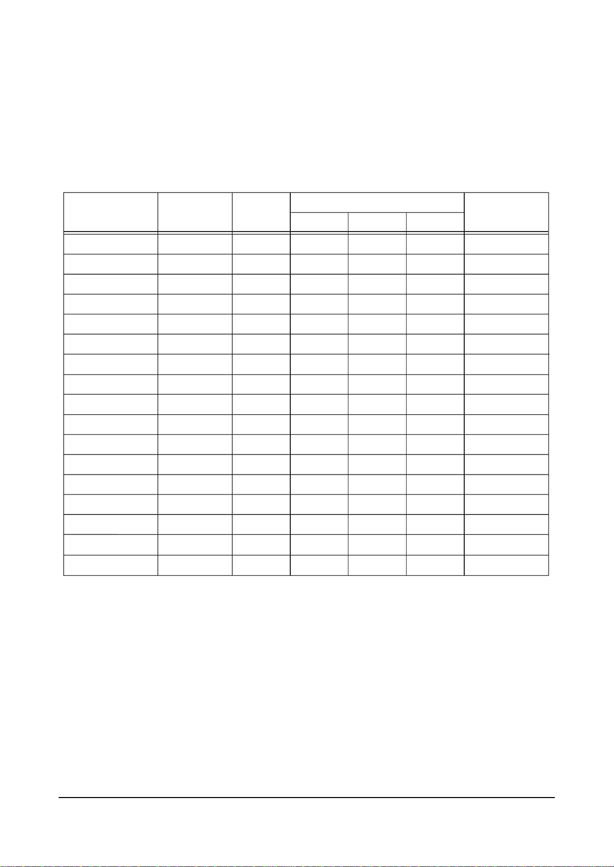
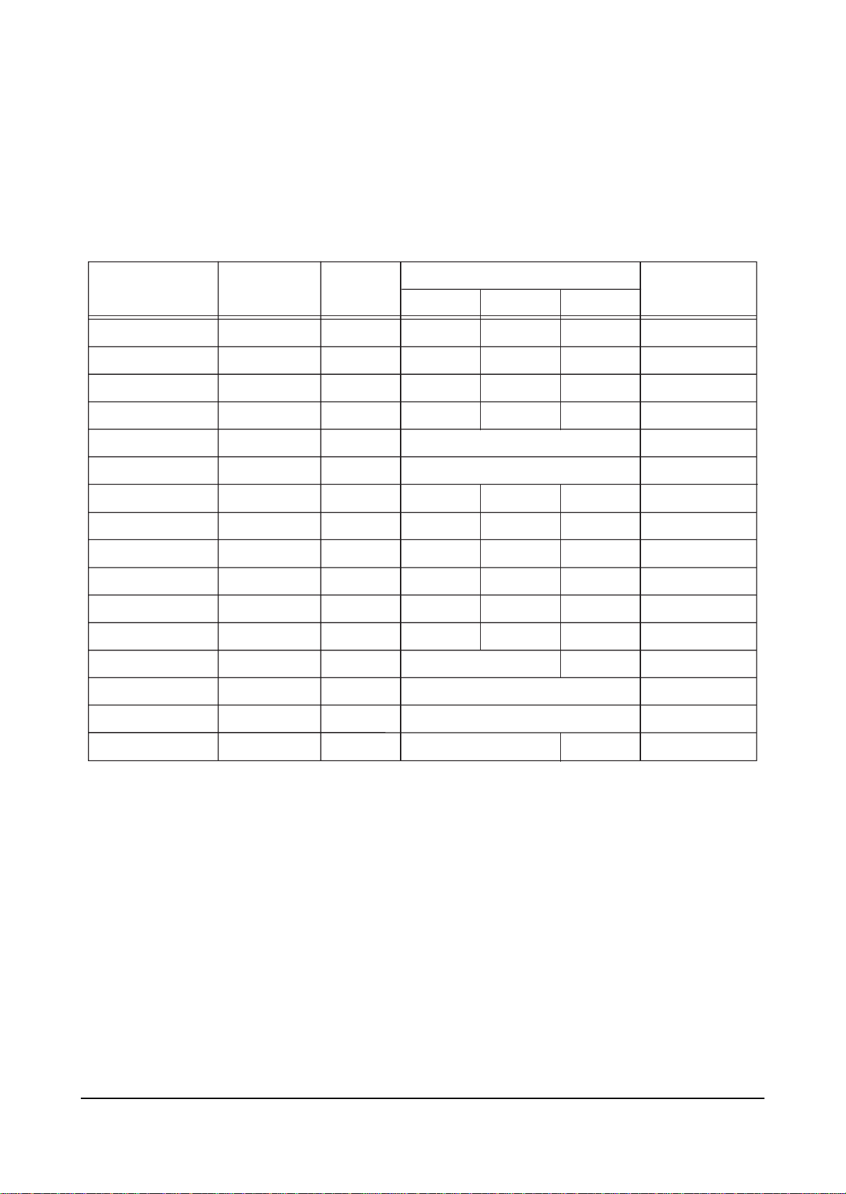
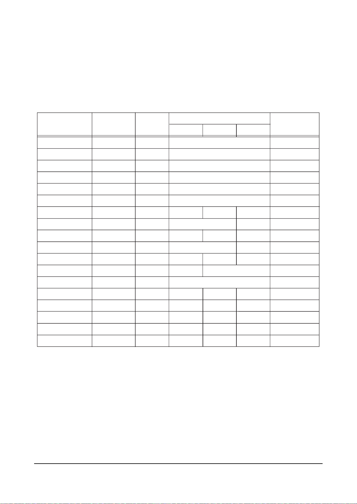
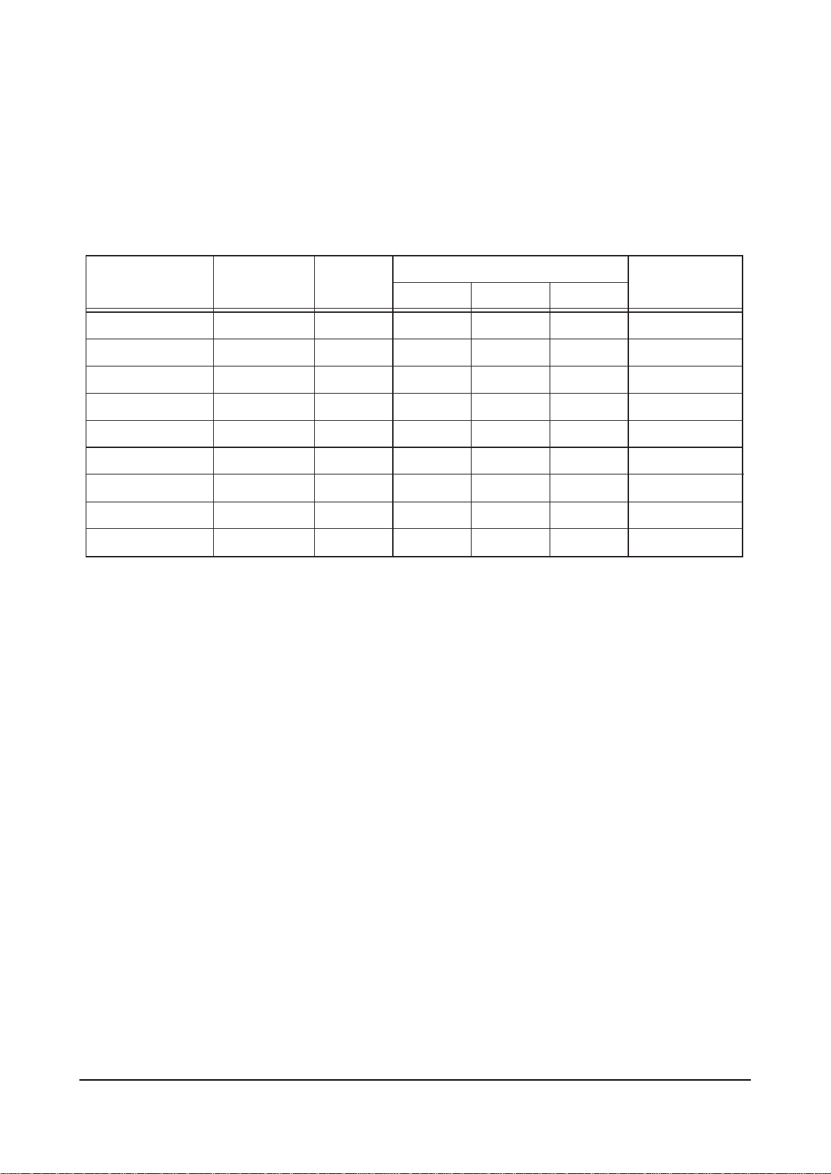
Electrical Parts List
Loc. No. Code No. Description ; Specification Remark Loc. No. Code No. Description ; Specification Remark
7. Electrical Parts List
7-1 HCN4226WX/XAA
You can search for the updated part code through ITSELF web site.
URL : http://itself.sec.samsung.co.kr
Page 58

....4 AA61-00615B BRACKET-EARTH;54J8,PBS,T0.5,-,-,-,- S.N.A
....4 AA61-00812A SPRING ETC-WIRE;PROJ,STS,3.6 S.N.A
...3 BP61-00091A HOLDER-CRT;PJTV,PCABS GF20%,BLUE S.N.A
...3 BP61-00079A HOLDER-DY;,PJTV,T0.5,NYLON66 V2 S.N.A
...3 AA63-00076B SPACER-LENS;FELT,W7,BLK,T0.8 S.N.A
..2 T0027 BP91-00421A ASSY CPT-G;0
...3 AA03-00201A CRT MONO;P16LSG03HKA,FREE,3.30mH,2.20mH, S.N.A
...3 T0117 AA26-30006F TRANS FBT-ANODE CAP ASS’Y;-,FWZ-50A001C,
...3 T0078 AA27-00249A DEFLECTION YOKE;-,DPD-5292AA,S/S,7,29.1
...3 T0076 AA39-00018A LEAD CONNECTOR-ASSY;,UL1015#22,UL/CSA,1P
...3 AA60-00125B SPACER-CRT;PROJ,SILICONE,D/GRAY S.N.A
...3 AA60-00126B SPACER-CAP;PROJ,EPDM,BLK S.N.A
...3 AA60-00127B SPACER-LENS;PROJ,SILICONE,D/GRAY S.N.A
...3 T0081 AA60-10011A SCREW-TAPTITE;-,SWRCH18A,M4,L12,HH,+,PC, S.N.A
...3 AA61-00056B BRACKET-LENS;PROJECTION,SECC,T1.6,-,-,-, S.N.A
...3 AA61-00807B CASE-COUPLER,G;PROJ,ALDC,T8,BLK S.N.A
...3 AA61-00809B HOLDER-CRT;PROJ,PC/ABS GF 20%,BLK S.N.A
...3 T0114 AA61-00810B HOLDER-CAP;PROJ,PC,CLR
...3 T0109 AA67-00187A LENS-ASSY;DELTA71,CLEAR A/B
...3 T0051 AA67-00189A LENS;DELTA71,GREEN C ELEMENT
...3 T0107 AA91-00722A ASSY-BRKT,CRT;,SECC T1.6,PROJ
....4 T0072 AA61-00473B BRACKET-CRT;53,SECC,T1.6,-,-,-,- S.N.A
....4 AA61-00615B BRACKET-EARTH;54J8,PBS,T0.5,-,-,-,- S.N.A
....4 AA61-00812A SPRING ETC-WIRE;PROJ,STS,3.6 S.N.A
...3 BP61-00079A HOLDER-DY;,PJTV,T0.5,NYLON66 V2 S.N.A
...3 AA63-00076B SPACER-LENS;FELT,W7,BLK,T0.8 S.N.A
..2 T0028 BP91-00422A ASSY CPT-B;0
...3 AA03-00202A CRT MONO;P16LSG03BMB,FREE,3.30mH,2.20mH, S.N.A
...3 T0117 AA26-30006F TRANS FBT-ANODE CAP ASS’Y;-,FWZ-50A001C,
...3 T0078 AA27-00249A DEFLECTION YOKE;-,DPD-5292AA,S/S,7,29.1
...3 T0079 AA33-00018A MAGNET CONVERGENCE;JH 92LT - 36F,-,29.1M
...3 T0076 AA39-00018A LEAD CONNECTOR-ASSY;,UL1015#22,UL/CSA,1P
...3 AA60-00126B SPACER-CAP;PROJ,EPDM,BLK S.N.A
...3 AA60-00127B SPACER-LENS;PROJ,SILICONE,D/GRAY S.N.A
...3 AA60-00128B SPACER-CRT;PROJ(65),SILICONE,D/GRAY S.N.A
...3 T0081 AA60-10011A SCREW-TAPTITE;-,SWRCH18A,M4,L12,HH,+,PC, S.N.A
...3 AA61-00056B BRACKET-LENS;PROJECTION,SECC,T1.6,-,-,-, S.N.A
...3 AA61-00808B CASE-COUPLER,B;PROJ,ALDC,T8,BLK S.N.A
...3 T0114 AA61-00810B HOLDER-CAP;PROJ,PC,CLR
...3 T0109 AA67-00187A LENS-ASSY;DELTA71,CLEAR A/B
...3 T0051 AA67-00190A LENS;DELTA71,CLEAR C ELEMENT
...3 T0107 AA91-00722A ASSY-BRKT,CRT;,SECC T1.6,PROJ
....4 T0072 AA61-00473B BRACKET-CRT;53,SECC,T1.6,-,-,-,- S.N.A
....4 AA61-00615B BRACKET-EARTH;54J8,PBS,T0.5,-,-,-,- S.N.A
....4 AA61-00812A SPRING ETC-WIRE;PROJ,STS,3.6 S.N.A
...3 BP61-00091A HOLDER-CRT;PJTV,PCABS GF20%,BLUE S.N.A
...3 BP61-00079A HOLDER-DY;,PJTV,T0.5,NYLON66 V2 S.N.A
...3 AA63-00076B SPACER-LENS;FELT,W7,BLK,T0.8 S.N.A
ASSY CHASSIS
1 M0017 BP91-00771L ASSY CHASSIS;HCN4226WX/XAA,P55A S.N.A
..2 T0098 AA94-08268A ASSY PCB MISC-VM;COMMANDO
...3 RZ120 2008-001097 R-FUSIBLE(S);33OHM,5%,1/2W,AC,BK,2.5X6.5
...3 AA97-07230MASSY AUTO-VM;COMMANDO S.N.A
....4 DZ106 0401-000005 DIODE-SWITCHING;1N4148,100V,200mA,DO-35,
....4 DZ105 0401-000005 DIODE-SWITCHING;1N4148,100V,200mA,DO-35,
....4 DZ102 0401-000005 DIODE-SWITCHING;1N4148,100V,200mA,DO-35,
....4 T0083 0402-000546 DIODE-RECTIFIER;TVR10G,400V,1.0A,DO-41,T
....4 T0083 0402-000546 DIODE-RECTIFIER;TVR10G,400V,1.0A,DO-41,T
....4 T0083 0402-000546 DIODE-RECTIFIER;TVR10G,400V,1.0A,DO-41,T
....4 QZ103 0501-000283 TR-SMALL SIGNAL;KSA539,PNP,400mW,TO-92,T
....4 QZ106 0501-000389 TR-SMALL SIGNAL;KSC815,NPN,400mW,TO-92,T
....4 QZ105 0501-000389 TR-SMALL SIGNAL;KSC815,NPN,400mW,TO-92,T
....4 QZ104 0501-000389 TR-SMALL SIGNAL;KSC815,NPN,400mW,TO-92,T
....4 RZ122 2001-000019 R-CARBON(S);10OHM,5%,1/2W,AA,TP,2.4X6.4M
....4 R125 2001-000221 R-CARBON;1.2KOHM,5%,1/8W,AA,TP,1.8X3.2MM
....4 R125 2001-000221 R-CARBON;1.2KOHM,5%,1/8W,AA,TP,1.8X3.2MM
....4 R125 2001-000241 R-CARBON;1.5KOHM,5%,1/8W,AA,TP,1.8X3.2MM
....4 R125 2001-000241 R-CARBON;1.5KOHM,5%,1/8W,AA,TP,1.8X3.2MM
....4 R125 2001-000258 R-CARBON;1.8KOHM,5%,1/8W,AA,TP,1.8X3.2MM
....4 R125 2001-000258 R-CARBON;1.8KOHM,5%,1/8W,AA,TP,1.8X3.2MM
....4 R125 2001-000331 R-CARBON;12KOHM,5%,1/8W,AA,TP,1.8X3.2MM
....4 R125 2001-000331 R-CARBON;12KOHM,5%,1/8W,AA,TP,1.8X3.2MM
....4 R125 2001-000554 R-CARBON;270OHM,5%,1/8W,AA,TP,1.8X3.2MM
....4 R125 2001-000666 R-CARBON;33OHM,5%,1/8W,AA,TP,1.8X3.2MM
....4 R125 2001-000832 R-CARBON;510OHM,5%,1/8W,AA,TP,1.8X3.2MM
....4 RZ110 2001-001100 R-CARBON(S);2.7OHM,5%,1/2W,AA,TP,2.4X6.4
....4 RZ104 2001-001100 R-CARBON(S);2.7OHM,5%,1/2W,AA,TP,2.4X6.4
....4 RZ105 2001-001139 R-CARBON(S);39KOHM,5%,1/2W,AA,TP,2.4X6.4
....4 RZ106 2001-001139 R-CARBON(S);39KOHM,5%,1/2W,AA,TP,2.4X6.4
....4 RZ114 2003-000532 R-METAL OXIDE(S);18ohm,5%,2W,AF,TP,4x12m
....4 RZ103 2003-000713 R-METAL OXIDE(S);47ohm,5%,2W,AF,TP,4x12m
....4 RZ111 2003-000713 R-METAL OXIDE(S);47ohm,5%,2W,AF,TP,4x12m
....4 RZ123 2003-002157 R-METAL OXIDE;220OHM,5%,2W,AG,TP,6X16MM
....4 RZ113 2003-002157 R-METAL OXIDE;220OHM,5%,2W,AG,TP,6X16MM
....4 RZ112 2003-002157 R-METAL OXIDE;220OHM,5%,2W,AG,TP,6X16MM
....4 RFZ101 2008-001086 R-FUSIBLE(S);3.3ohm,5%,2W,AG,TP,3.9x12mm
....4 C598 2201-000193 C-CERAMIC,DISC;0.01NF,0.25PF,50V,C0G,TP,
....4 C598 2201-000193 C-CERAMIC,DISC;0.01NF,0.25PF,50V,C0G,TP,
....4 C598 2201-000516 C-CERAMIC,DISC;4.7NF,+100-0%,500V,Y5U,TP
....4 C598 2201-000516 C-CERAMIC,DISC;4.7NF,+100-0%,500V,Y5U,TP
....4 C598 2201-000604 C-CERAMIC,DISC;0.056NF,+100-0%,500V,SL,T
....4 C701 2401-000480 C-AL;10uF,20%,50V,GP,TP,5x11,5
....4 C701 2401-000832 C-AL;220uF,20%,25V,GP,TP,8x11.5,5
....4 C701 2401-001157 C-AL;33uF,20%,160V,GP,TP,12.5x20,5
....4 C701 2401-001220 C-AL;4.7uF,20%,160V,GP,TP,8x11.5,5
....4 C701 2401-001220 C-AL;4.7uF,20%,160V,GP,TP,8x11.5,5
....4 C701 2401-001513 C-AL;47uF,20%,16V,WT,TP,5x11,5
....4 C701 2401-002144 C-AL;47uF,20%,16V,GP,TP,5x11,5
....4 LZ101 2701-000002 INDUCTOR-AXIAL;100uH,10%,4.2x9.8mm
....4 CN906 3711-002642 CONNECTOR-HEADER;BOX,3P,1R,2.5mm,STRAIGH
....4 CN906 3711-002642 CONNECTOR-HEADER;BOX,3P,1R,2.5mm,STRAIGH
....4 CN906 3711-002642 CONNECTOR-HEADER;BOX,3P,1R,2.5mm,STRAIGH
....4 PCB AA41-00611A PCB-VM;HCM4215W,FR-1,1L,A,1.6T,245X245,P S.N.A
...3 QZ101 AA96-00243M ASSY H/S;-,AMP,AA62-000450A,2SA1011,HERC S.N.A
....4 0205-000129 GREASE-SILICON;SC102,JAPAN S.N.A
....4 T0090 0502-000131 TR-POWER;2SA1011-D,PNP,1.2W,TO-220,-,60
....4 T0081 6003-000335 SCREW-TAPTITE;RH,+,2S,M3,L8,ZPC(YEL),SWR S.N.A
....4 AA62-00045A HEAT SINK-PS;-,-,T1.0,-,-,DREAM,-,-,-,-, S.N.A
...3 QZ102 AA96-00243L ASSY H/S;-,CRT,AA62-000450A,2SC2344,HERC S.N.A
....4 0205-000129 GREASE-SILICON;SC102,JAPAN S.N.A
....4 T0090 0502-000153 TR-POWER;2SC2344-D,NPN,1.2W,TO-220,-,60
....4 T0081 6003-000335 SCREW-TAPTITE;RH,+,2S,M3,L8,ZPC(YEL),SWR S.N.A
....4 AA62-00045A HEAT SINK-PS;-,-,T1.0,-,-,DREAM,-,-,-,-, S.N.A
...3 0202-000187 SOLDER-WIRE FLUX;-,RS60S,D1.2,63Sn/37Pb S.N.A
...3 T0121 3301-001201 CORE-FERRITE;AE,21x11x32mm,1500,280G
...3 T0079 AA33-00017A MAGNET CONVERGENCE;JH 92LT - 29G,-,29.1M
...3 T0081 6003-001023 SCREW-TAPTITE;RWH,+,B,M3,L10,ZPC(YEL),SW S.N.A
...3 T0076 AA39-20055C LEAD CONNECTOR-ASSY;,6P,500,YBNH025-06,6
..2 T0105 AA94-08270A ASSY PCB MISC-DY JACK;COMMANDO
...3 AA97-07230N ASSY AUTO;COMMANDO S.N.A
....4 R301 2001-001107 R-CARBON(S);220ohm,5%,1/2W,AA,TP,2.4x6.4
....4 R302 2001-001107 R-CARBON(S);220ohm,5%,1/2W,AA,TP,2.4x6.4
....4 R303 2001-001107 R-CARBON(S);220ohm,5%,1/2W,AA,TP,2.4x6.4
....4 PCB AA41-00632A PCB-DY CONNECTION;HCM4215W,FR-1,1L,A,1.6 S.N.A
...3 0202-000187 SOLDER-WIRE FLUX;-,RS60S,D1.2,63Sn/37Pb S.N.A
...3 GT01 AA60-40012D PIN-GT,ASSY;T1.6,6-12.5-,NYLON66 S.N.A
...3 GT05 AA60-40012D PIN-GT,ASSY;T1.6,6-12.5-,NYLON66 S.N.A
...3 GT09 AA60-40012D PIN-GT,ASSY;T1.6,6-12.5-,NYLON66 S.N.A
...3 GT13 AA60-40012D PIN-GT,ASSY;T1.6,6-12.5-,NYLON66 S.N.A
...3 AA61-01197A HOLDER-PCB,DY;COMANDO,ABS V0,BLK S.N.A
..2 T0097 AA94-08574A ASSY PCB MISC-PWR-DEF; ,HCM4215W,P55A
...3 0202-000187 SOLDER-WIRE FLUX;-,RS60S,D1.2,63Sn/37Pb S.N.A
...3 T0083 0402-000236 DIODE-RECTIFIER;GI824,400V,5A,-,TP
...3 T0083 0402-000250 DIODE-RECTIFIER;RG4C,1000V,1A,...3 NT801S 1404-001195 THERMISTOR-NTC;5.1ohm,15%,2900,27mW/C,BK
...3 CX802S 2306-000112 C-FILM,MPPF;100nF,20%,250V,BK,-,15mm
...3 CX801S 2306-000112 C-FILM,MPPF;100nF,20%,250V,BK,-,15mm
...3 C701 2401-000701 C-AL;2200uF,20%,250V,GP,-,35x70mm,1
...3 C701 2401-000701 C-AL;2200uF,20%,250V,GP,-,35x70mm,1
...3 C701 2401-002251 C-AL;470uF,20%,200V,GP,BK,25x40mm,1
...3 C701 2401-003076 C-AL;3300UF,20%,50V,WT,BK,18X35.5MM,7.5
...3 C701 2401-003076 C-AL;3300UF,20%,50V,WT,BK,18X35.5MM,7.5
...3 C701 2401-003076 C-AL;3300UF,20%,50V,WT,BK,18X35.5MM,7.5
...3 FP801S 3601-000300 FUSE-CARTRIDGE;250V,6.3A,SLOW-BLOW,GLASS
...3 T481 AA26-00091A TRANS-HV-STORAGE;4mH,-,14P,830uH,180V,10
...3 T444S AA26-00100A TRANS FBT;FFA97513L,CT29A7DR,0.3mH,-,-,...3 T431 AA26-50001U TRANS-HORIZ.DRIVE;-,-,-,28mH,-,-,105uH,...3 T461 AA26-50001V TRANS-HORIZ.DRIVE;-,-,-,6.0mH,-,-,113uH,
...3 LR401S AA27-30003M COIL LINEARITY;-,5uH,OWA14x15,USRC0.1x60
Electrical Parts List
7-2 Samsung Electronics
Loc. No. Code No. Description ; Specification Remark Loc. No. Code No. Description ; Specification Remark
Page 59

...3 T0076 AA39-00180A LEAD CONNECTOR-ASSY;,14P,100MM,YBNH250-1
...3 D856 AA96-00243E ASSY H/S;-,SOUND,AA62-00045A,FMG-G26S S.N.A
...3 D855 AA96-00243E ASSY H/S;-,SOUND,AA62-00045A,FMG-G26S S.N.A
....4 0205-000129 GREASE-SILICON;SC102,JAPAN S.N.A
....4 T0083 0402-000231 DIODE-RECTIFIER;FMG-G26S,600V,4A,TO-220F
....4 T0081 6003-000335 SCREW-TAPTITE;RH,+,2S,M3,L8,ZPC(YEL),SWR S.N.A
....4 AA62-00045A HEAT SINK-PS;-,-,T1.0,-,-,DREAM,-,-,-,-, S.N.A
...3 Q433 AA96-00243H ASSY H/S;-,POWER,AA62-00045A,KSD73Y,C17A S.N.A
....4 0205-000129 GREASE-SILICON;SC102,JAPAN S.N.A
....4 T0090 0502-000298 TR-POWER;KSD73,NPN,30000mW,TO-220,TP,120
....4 T0081 6003-000335 SCREW-TAPTITE;RH,+,2S,M3,L8,ZPC(YEL),SWR S.N.A
....4 AA62-00045A HEAT SINK-PS;-,-,T1.0,-,-,DREAM,-,-,-,-, S.N.A
...3 IC831S AA96-00275J ASSY H/S;SCREW,SILICON-OIL,AA62-00051A,S S.N.A
....4 CIS 0205-000129 GREASE-SILICON;SC102,JAPAN S.N.A
....4 T0081 6003-000333 SCREW-TAPTITE;RH,+,2S,M3,L10,ZPC(YEL),SW S.N.A
....4 IC063 AA13-00105A IC HYBRID;STR-X6456,7,-20TO+125,DIP,21A,
....4 CIS AA62-00051A HEAT SINK-PS;-,-,-,SILVER,HOLE 31mm,ALL, S.N.A
...3 D811S AA96-00276A ASSY H/S;-,BRIDGE,AA62-00052A,RBV606,WAS S.N.A
....4 0205-000129 GREASE-SILICON;SC102,JAPAN S.N.A
....4 T0083 0402-000549 DIODE-BRIDGE;RBV606,600V,6A,-,BK
....4 T0081 6003-000335 SCREW-TAPTITE;RH,+,2S,M3,L8,ZPC(YEL),SWR S.N.A
....4 AA60-30003A WASHER;T1.5,SBHG-1 S.N.A
....4 AA62-00052A HEAT SINK-PS;-,-,-,SILVER,HOLE 18.5mm, 2 S.N.A
...3 IC301 AA96-00623A ASSY H/S;-,POWER,AA62-00056A,LA7845 S.N.A
....4 0205-000129 GREASE-SILICON;SC102,JAPAN S.N.A
....4 T0088 1204-000517 IC-VERTICAL DEF.;LA7845,SIP,7P,-,PLASTIC
....4 T0081 6003-000334 SCREW-TAPTITE;RH,+,2S,M3,L6,ZPC(YEL),SWR
....4 AA62-00056A HEAT SINK-PS;-,-,T1.0,-,41*35*70,D2,-,-, S.N.A
...3 AA97-07506Z ASSY AUTO-PWR DEF;HCM4215W S.N.A
....4 D478 0401-000005 DIODE-SWITCHING;1N4148,100V,200mA,DO-35,
....4 D479 0401-000005 DIODE-SWITCHING;1N4148,100V,200mA,DO-35,
....4 DR401S 0401-000005 DIODE-SWITCHING;1N4148,100V,200mA,DO-35,
....4 DR402S 0401-000005 DIODE-SWITCHING;1N4148,100V,200mA,DO-35,
....4 D385 0401-000005 DIODE-SWITCHING;1N4148,100V,200mA,DO-35,
....4 D436 0401-000005 DIODE-SWITCHING;1N4148,100V,200mA,DO-35,
....4 D442 0401-000005 DIODE-SWITCHING;1N4148,100V,200mA,DO-35,
....4 D443 0401-000005 DIODE-SWITCHING;1N4148,100V,200mA,DO-35,
....4 D477 0401-000005 DIODE-SWITCHING;1N4148,100V,200mA,DO-35,
....4 D301 0401-000005 DIODE-SWITCHING;1N4148,100V,200mA,DO-35,
....4 DS802 0401-000006 DIODE-SWITCHING;BAV21,250V,250mA,DO-35,T
....4 DS804 0401-000006 DIODE-SWITCHING;BAV21,250V,250mA,DO-35,T
....4 T0083 0402-000132 DIODE-RECTIFIER;1N4004,400V,1A,DO-41,TP
....4 T0083 0402-000132 DIODE-RECTIFIER;1N4004,400V,1A,DO-41,TP
....4 T0083 0402-000132 DIODE-RECTIFIER;1N4004,400V,1A,DO-41,TP
....4 T0083 0402-000132 DIODE-RECTIFIER;1N4004,400V,1A,DO-41,TP
....4 T0083 0402-000132 DIODE-RECTIFIER;1N4004,400V,1A,DO-41,TP
....4 T0083 0402-000132 DIODE-RECTIFIER;1N4004,400V,1A,DO-41,TP
....4 T0083 0402-000254 DIODE-RECTIFIER;RGP10J,600V,1A,DO-41,TP
....4 T0083 0402-000534 DIODE-RECTIFIER;RG10V,400V,1.2A,DO-201,T
....4 T0083 0402-000534 DIODE-RECTIFIER;RG10V,400V,1.2A,DO-201,T
....4 T0083 0402-000534 DIODE-RECTIFIER;RG10V,400V,1.2A,DO-201,T
....4 T0083 0402-000534 DIODE-RECTIFIER;RG10V,400V,1.2A,DO-201,T
....4 T0083 0402-000537 DIODE-RECTIFIER;RH1A,600V,0.6A,DO-204AC
....4 T0083 0402-000546 DIODE-RECTIFIER;TVR10G,400V,1.0A,DO-41,T
....4 T0083 0402-000546 DIODE-RECTIFIER;TVR10G,400V,1.0A,DO-41,T
....4 T0083 0402-000546 DIODE-RECTIFIER;TVR10G,400V,1.0A,DO-41,T
....4 T0083 0402-000546 DIODE-RECTIFIER;TVR10G,400V,1.0A,DO-41,T
....4 T0083 0402-000546 DIODE-RECTIFIER;TVR10G,400V,1.0A,DO-41,T
....4 DZ016 0403-000704 DIODE-ZENER;TZP7.5B,7.5V,7.5-8.4V,1W,DO-
....4 DZ016 0403-000716 DIODE-ZENER;MTZJ4.7B,4.7V,4.55-4.8V,500m
....4 DZ016 0403-000720 DIODE-ZENER;MTZJ9.1B,9.1V,8.57-9.01V,500
....4 DZ016 0403-000720 DIODE-ZENER;MTZJ9.1B,9.1V,8.57-9.01V,500
....4 DZ016 0403-000720 DIODE-ZENER;MTZJ9.1B,9.1V,8.57-9.01V,500
....4 DZ016 0403-000734 DIODE-ZENER;TZP15B,15V,14.7-16.5V,1W,DO-
....4 DZ016 0403-001167 DIODE-ZENER;MTZJ30D,30V,29.02-30.51V,500
....4 DZ016 0403-001316 DIODE-ZENER;MTZJ3.0A,2.85-3.07V,500mW,DO
....4 DZ016 0403-001319 DIODE-ZENER;MTZJ4.7C,4.68-4.93V,500mW,DO
....4 DZ016 0403-001319 DIODE-ZENER;MTZJ4.7C,4.68-4.93V,500mW,DO
....4 DZ016 0403-001325 DIODE-ZENER;MTZJ15C,14.35-15.09V,500mW,D
....4 DZ016 0403-001325 DIODE-ZENER;MTZJ15C,14.35-15.09V,500mW,D
....4 DZ016 0403-001325 DIODE-ZENER;MTZJ15C,14.35-15.09V,500mW,D
....4 DZ016 0403-001327 DIODE-ZENER;MTZJ18A,16.22-17.06V,500mW,D
....4 DZ016 0403-001327 DIODE-ZENER;MTZJ18A,16.22-17.06V,500mW,D
....4 DZ016 0403-001327 DIODE-ZENER;MTZJ18A,16.22-17.06V,500mW,D
....4 DZ016 0403-001328 DIODE-ZENER;MTZJ22A,20.15-21.20V,500mW,D
....4 DZ016 0403-001329 DIODE-ZENER;MTZJ24B,22.61-23.77V,500mW,D
....4 DZ016 0403-001329 DIODE-ZENER;MTZJ24B,22.61-23.77V,500mW,D
....4 DZ016 0403-001330 DIODE-ZENER;MTZJ30A,26.99-28.39V,500mW,D
....4 DZ016 0403-001330 DIODE-ZENER;MTZJ30A,26.99-28.39V,500mW,D
....4 DS805 0404-001056 DIODE-SCHOTTKY;RK16,60V,1.5A,DO-204AC,TP
....4 QR401S 0501-000283 TR-SMALL SIGNAL;KSA539,PNP,400mW,TO-92,T
....4 Q482 0501-000283 TR-SMALL SIGNAL;KSA539,PNP,400mW,TO-92,T
....4 Q432 0501-000283 TR-SMALL SIGNAL;KSA539,PNP,400mW,TO-92,T
....4 Q461 0501-000389 TR-SMALL SIGNAL;KSC815,NPN,400mW,TO-92,T
....4 Q471 0501-000389 TR-SMALL SIGNAL;KSC815,NPN,400mW,TO-92,T
....4 Q474 0501-000389 TR-SMALL SIGNAL;KSC815,NPN,400mW,TO-92,T
....4 Q481 0501-000389 TR-SMALL SIGNAL;KSC815,NPN,400mW,TO-92,T
....4 Q851 0501-000389 TR-SMALL SIGNAL;KSC815,NPN,400mW,TO-92,T
....4 QS801 0501-000389 TR-SMALL SIGNAL;KSC815,NPN,400mW,TO-92,T
....4 QS802 0501-000389 TR-SMALL SIGNAL;KSC815,NPN,400mW,TO-92,T
....4 Q301 0501-000389 TR-SMALL SIGNAL;KSC815,NPN,400mW,TO-92,T
....4 Q381 0501-000389 TR-SMALL SIGNAL;KSC815,NPN,400mW,TO-92,T
....4 Q382 0501-000389 TR-SMALL SIGNAL;KSC815,NPN,400mW,TO-92,T
....4 Q401 0501-000389 TR-SMALL SIGNAL;KSC815,NPN,400mW,TO-92,T
....4 Q402 0501-000389 TR-SMALL SIGNAL;KSC815,NPN,400mW,TO-92,T
....4 Q421 0501-000389 TR-SMALL SIGNAL;KSC815,NPN,400mW,TO-92,T
....4 Q451 0501-000389 TR-SMALL SIGNAL;KSC815,NPN,400mW,TO-92,T
....4 IC012 1203-001217 IC-POSI.ADJUST REG.;431,TO-92,3P,4.58MIL
....4 VP801S 1405-000152 VARISTOR;560V,2500A,14x8.5mm,TP
....4 R125 2001-000005 R-CARBON;390ohm,5%,1/8W,AA,TP,1.8x3.2mm
....4 R125 2001-000006 R-CARBON;2.4KOHM,5%,1/8W,AA,TP,1.8X3.2MM
....4 R125 2001-000009 R-CARBON;20KOHM,5%,1/8W,AA,TP,1.8X3.2MM
....4 R125 2001-000009 R-CARBON;20KOHM,5%,1/8W,AA,TP,1.8X3.2MM
....4 R308 2001-000016 R-CARBON(S);1OHM,5%,1/2W,AA,TP,2.4X6.4MM
....4 R470 2001-000028 R-CARBON(S);100OHM,5%,1/2W,AA,TP,2.4X6.4
....4 R422 2001-000028 R-CARBON(S);100OHM,5%,1/2W,AA,TP,2.4X6.4
....4 R836 2001-000052 R-CARBON(S);3.3KOHM,5%,1/2W,AA,TP,2.4X6.
....4 R493 2001-000052 R-CARBON(S);3.3KOHM,5%,1/2W,AA,TP,2.4X6.
....4 RS804 2001-000066 R-CARBON(S);10KOHM,5%,1/2W,AA,TP,2.4X6.4
....4 R855 2001-000066 R-CARBON(S);10KOHM,5%,1/2W,AA,TP,2.4X6.4
....4 RS808 2001-000066 R-CARBON(S);10KOHM,5%,1/2W,AA,TP,2.4X6.4
....4 RS803 2001-000085 R-CARBON(S);100KOHM,5%,1/2W,AA,TP,2.4X6.
....4 R814 2001-000085 R-CARBON(S);100KOHM,5%,1/2W,AA,TP,2.4X6.
....4 R813 2001-000085 R-CARBON(S);100KOHM,5%,1/2W,AA,TP,2.4X6.
....4 R812 2001-000085 R-CARBON(S);100KOHM,5%,1/2W,AA,TP,2.4X6.
....4 R439 2001-000085 R-CARBON(S);100KOHM,5%,1/2W,AA,TP,2.4X6.
....4 R438 2001-000085 R-CARBON(S);100KOHM,5%,1/2W,AA,TP,2.4X6.
....4 R811 2001-000085 R-CARBON(S);100KOHM,5%,1/2W,AA,TP,2.4X6.
....4 R834 2001-000109 R-CARBON(S);470OHM,5%,1/2W,AA,TP,2.4X6.4
....4 R125 2001-000258 R-CARBON;1.8KOHM,5%,1/8W,AA,TP,1.8X3.2MM
....4 R125 2001-000262 R-CARBON;1.8MOHM,5%,1/8W,AA,TP,1.8X3.2MM
....4 R125 2001-000273 R-CARBON;100KOHM,5%,1/8W,AA,TP,1.8X3.2MM
....4 R125 2001-000281 R-CARBON;100OHM,5%,1/8W,AA,TP,1.8X3.2MM
....4 R125 2001-000290 R-CARBON;10KOHM,5%,1/8W,AA,TP,1.8X3.2MM
....4 R125 2001-000290 R-CARBON;10KOHM,5%,1/8W,AA,TP,1.8X3.2MM
....4 R125 2001-000290 R-CARBON;10KOHM,5%,1/8W,AA,TP,1.8X3.2MM
....4 R125 2001-000290 R-CARBON;10KOHM,5%,1/8W,AA,TP,1.8X3.2MM
....4 R125 2001-000362 R-CARBON;150OHM,5%,1/8W,AA,TP,1.8X3.2MM
....4 R125 2001-000429 R-CARBON;1KOHM,5%,1/8W,AA,TP,1.8X3.2MM
....4 R125 2001-000429 R-CARBON;1KOHM,5%,1/8W,AA,TP,1.8X3.2MM
....4 R125 2001-000429 R-CARBON;1KOHM,5%,1/8W,AA,TP,1.8X3.2MM
....4 R125 2001-000449 R-CARBON;2.2KOHM,5%,1/8W,AA,TP,1.8X3.2MM
....4 R125 2001-000508 R-CARBON;220KOHM,5%,1/8W,AA,TP,1.8X3.2MM
....4 R125 2001-000515 R-CARBON;220OHM,5%,1/8W,AA,TP,1.8X3.2MM
....4 R125 2001-000522 R-CARBON;22KOHM,5%,1/8W,AA,TP,1.8X3.2MM
....4 R125 2001-000577 R-CARBON;2KOHM,5%,1/8W,AA,TP,1.8X3.2MM
....4 R125 2001-000577 R-CARBON;2KOHM,5%,1/8W,AA,TP,1.8X3.2MM
....4 R125 2001-000577 R-CARBON;2KOHM,5%,1/8W,AA,TP,1.8X3.2MM
....4 R125 2001-000613 R-CARBON;3.9KOHM,5%,1/8W,AA,TP,1.8X3.2MM
....4 R125 2001-000613 R-CARBON;3.9KOHM,5%,1/8W,AA,TP,1.8X3.2MM
....4 R125 2001-000734 R-CARBON;4.7KOHM,5%,1/8W,AA,TP,1.8X3.2MM
....4 R125 2001-000734 R-CARBON;4.7KOHM,5%,1/8W,AA,TP,1.8X3.2MM
....4 R125 2001-000734 R-CARBON;4.7KOHM,5%,1/8W,AA,TP,1.8X3.2MM
....4 R125 2001-000734 R-CARBON;4.7KOHM,5%,1/8W,AA,TP,1.8X3.2MM
....4 R125 2001-000734 R-CARBON;4.7KOHM,5%,1/8W,AA,TP,1.8X3.2MM
....4 R125 2001-000761 R-CARBON;430OHM,5%,1/8W,AA,TP,1.8X3.2MM
....4 R125 2001-000761 R-CARBON;430OHM,5%,1/8W,AA,TP,1.8X3.2MM
....4 R125 2001-000761 R-CARBON;430OHM,5%,1/8W,AA,TP,1.8X3.2MM
....4 R125 2001-000761 R-CARBON;430OHM,5%,1/8W,AA,TP,1.8X3.2MM
....4 R125 2001-000761 R-CARBON;430OHM,5%,1/8W,AA,TP,1.8X3.2MM
....4 R125 2001-000786 R-CARBON;47KOHM,5%,1/8W,AA,TP,1.8X3.2MM
....4 R125 2001-000800 R-CARBON;5.1KOHM,5%,1/8W,AA,TP,1.8X3.2MM
....4 R125 2001-000800 R-CARBON;5.1KOHM,5%,1/8W,AA,TP,1.8X3.2MM
....4 R125 2001-000812 R-CARBON;5.6KOHM,5%,1/8W,AA,TP,1.8X3.2MM
Electrical Parts List
Samsung Electronics 7-3
Loc. No. Code No. Description ; Specification Remark Loc. No. Code No. Description ; Specification Remark
Page 60

....4 R125 2001-000924 R-CARBON;680OHM,5%,1/8W,AA,TP,1.8X3.2MM
....4 R125 2001-001031 R-CARBON;91KOHM,5%,1/8W,AA,TP,1.8X3.2MM
....4 RS807 2001-001088 R-CARBON(S);1KOHM,5%,1/2W,AA,TP,2.4X6.4M
....4 R854 2001-001088 R-CARBON(S);1KOHM,5%,1/2W,AA,TP,2.4X6.4M
....4 R839 2001-001088 R-CARBON(S);1KOHM,5%,1/2W,AA,TP,2.4X6.4M
....4 R413 2001-001088 R-CARBON(S);1KOHM,5%,1/2W,AA,TP,2.4X6.4M
....4 RR401S 2001-001088 R-CARBON(S);1KOHM,5%,1/2W,AA,TP,2.4X6.4M
....4 R434 2001-001088 R-CARBON(S);1KOHM,5%,1/2W,AA,TP,2.4X6.4M
....4 R837 2001-001108 R-CARBON(S);22KOHM,5%,1/2W,AA,TP,2.4X6.4
....4 R468 2001-001122 R-CARBON(S);3.9KOHM,5%,1/2W,AA,TP,2.4X6.
....4 RS802 2001-001124 R-CARBON(S);3.9OHM,5%,1/2W,AA,TP,2.4X6.4
....4 R433 2001-001155 R-CARBON(S);5.6KOHM,5%,1/2W,AA,TP,2.4X6.
....4 R410 2001-001155 R-CARBON(S);5.6KOHM,5%,1/2W,AA,TP,2.4X6.
....4 RS806 2001-001168 R-CARBON(S);6.8KOHM,5%,1/2W,AA,TP,2.4X6.
....4 R459 2001-001192 R-CARBON(S);820OHM,5%,1/2W,AA,TP,2.4X6.4
....4 R851 2001-001196 R-CARBON(S);9.1KOHM,5%,1/2W,AA,TP,2.4X6.
....4 RP801S 2002-001010 R-COMPOSITION;1.8Mohm,5%,1/2W,AA,TP,3.7x
....4 RY801S 2002-001013 R-COMPOSITION;4.7Mohm,5%,1/2W,AA,TP,3.7x
....4 R428 2002-001017 R-COMPOSITION;1Kohm,10%,1/2W,AA,TP,3.7x9
....4 R428A 2002-001017 R-COMPOSITION;1Kohm,10%,1/2W,AA,TP,3.7x9
....4 R429 2003-000586 R-METAL OXIDE(S);22Kohm,5%,2W,AF,TP,4x12
....4 R430 2003-000586 R-METAL OXIDE(S);22Kohm,5%,2W,AF,TP,4x12
....4 R463 2003-001024 R-METAL OXIDE(S);150ohm,5%,2W,AF,TP,3.9x
....4 R310 2003-001024 R-METAL OXIDE(S);150ohm,5%,2W,AF,TP,3.9x
....4 R460 2003-002044 R-METAL OXIDE(S);100ohm,5%,1W,AF,TP,2.5x
....4 R426 2003-002153 R-METAL OXIDE;4.7OHM,5%,2W,AG,TP,6X16MM
....4 R443A 2003-002156 R-METAL OXIDE;560OHM,5%,2W,AG,TP,6X16MM
....4 R443 2003-002156 R-METAL OXIDE;560OHM,5%,2W,AG,TP,6X16MM
....4 R464 2003-002158 R-METAL OXIDE;0.68OHM,5%,1W,AG,TP,4.3X12
....4 R421 2003-002159 R-METAL OXIDE;150OHM,5%,1W,AG,TP,4.3X12M
....4 R024 2004-001369 R-METAL(S);1.2Kohm,1%,1/2W,AA,TP,2.4x6.4
....4 R024 2004-001386 R-METAL(S);16.9Kohm,1%,1/2W,AA,TP,2.4x6.
....4 R024 2004-001395 R-METAL(S);330Kohm,2%,1/2W,AA,TP,2.4x6.4
....4 R024 2004-001408 R-METAL(S);91Kohm,1%,1/2W,AA,TP,2.4x6.4m
....4 R024 2004-001892 R-METAL(S);162Kohm,1%,1/2W,AA,TP,2.5x6.5
....4 R024 2004-001892 R-METAL(S);162Kohm,1%,1/2W,AA,TP,2.5x6.5
....4 R024 2004-001897 R-METAL(S);43.2Kohm,1%,1/2W,AA,TP,2.5x6.
....4 R024 2004-001897 R-METAL(S);43.2Kohm,1%,1/2W,AA,TP,2.5x6.
....4 R024 2004-001984 R-METAL(S);26.7Kohm,1%,1/2W,AA,TP,2.4x6.
....4 R024 2004-001984 R-METAL(S);26.7Kohm,1%,1/2W,AA,TP,2.4x6.
....4 R024 2004-001984 R-METAL(S);26.7Kohm,1%,1/2W,AA,TP,2.4x6.
....4 R024 2004-002011 R-METAL(S);110Kohm,1%,1/2W,AA,TP,2.4x6.4
....4 R024 2004-004001 R-METAL(S);180Kohm,1%,1/2W,AA,TP,2.5x6.5
....4 R024 2004-004046 R-METAL(S);430Kohm,1%,1/2W,AA,TP,2.5x6.5
....4 R024 2004-004046 R-METAL(S);430Kohm,1%,1/2W,AA,TP,2.5x6.5
....4 R024 2004-004366 R-METAL(S);1.3Kohm,1%,1/2W,AA,TP,2.5x6.5
....4 R472 2008-000252 R-FUSIBLE(S);0.47ohm,10%,1/2W,AF,TP,2.5x
....4 R465 2008-000253 R-FUSIBLE(S);0.47ohm,5%,1W,AF,TP,3.9x10m
....4 R449 2008-000253 R-FUSIBLE(S);0.47ohm,5%,1W,AF,TP,3.9x10m
....4 R445 2008-000253 R-FUSIBLE(S);0.47ohm,5%,1W,AF,TP,3.9x10m
....4 R442 2008-000253 R-FUSIBLE(S);0.47ohm,5%,1W,AF,TP,3.9x10m
....4 R441 2008-000253 R-FUSIBLE(S);0.47ohm,5%,1W,AF,TP,3.9x10m
....4 R447 2008-000253 R-FUSIBLE(S);0.47ohm,5%,1W,AF,TP,3.9x10m
....4 R442A 2008-000253 R-FUSIBLE(S);0.47ohm,5%,1W,AF,TP,3.9x10m
....4 R307 2008-000290 R-FUSIBLE(S);2.4ohm,5%,2W,AF,TP,3.9x10mm
....4 R486 2008-001018 R-FUSIBLE(S);0.47ohm,10%,2W,AF,TP,3.9x10
....4 R838 2008-001053 R-FUSIBLE;22ohm,5%,1/2W,AF,TP,2.5x6.5mm
....4 R437 2008-001087 R-FUSIBLE(S);1.8ohm,5%,2W,AG,TP,3.9x12mm
....4 R485 2008-001137 R-FUSIBLE(S);3.3ohm,5%,1W,AF,TP,3.9x10mm
....4 R405 2009-001109 R-TEMPERATURE;240ohm,5%,1/4W,AA,TP,2.3x6
....4 RR471S 2103-001024 VR-SEMI;50Kohm,25%,0.3W,TOP
....4 RR402S 2103-001086 VR-SEMI;100KOHM,25%,0.3W,TOP
....4 C598 2201-000119 C-CERAMIC,DISC;100NF,+80-20%,50V,Y5V,TP,
....4 C598 2201-000119 C-CERAMIC,DISC;100NF,+80-20%,50V,Y5V,TP,
....4 C598 2201-000119 C-CERAMIC,DISC;100NF,+80-20%,50V,Y5V,TP,
....4 C598 2201-000119 C-CERAMIC,DISC;100NF,+80-20%,50V,Y5V,TP,
....4 C598 2201-000132 C-CERAMIC,DISC;0.1NF,10%,500V,Y5P,TP,6.5
....4 C598 2201-000132 C-CERAMIC,DISC;0.1NF,10%,500V,Y5P,TP,6.5
....4 C598 2201-000132 C-CERAMIC,DISC;0.1NF,10%,500V,Y5P,TP,6.5
....4 C598 2201-000132 C-CERAMIC,DISC;0.1NF,10%,500V,Y5P,TP,6.5
....4 C598 2201-000132 C-CERAMIC,DISC;0.1NF,10%,500V,Y5P,TP,6.5
....4 C598 2201-000138 C-CERAMIC,DISC;0.1NF,10%,50V,Y5P,TP,4X4M
....4 C598 2201-000146 C-CERAMIC,DISC;0.1NF,5%,50V,SL,TP,5X3.5M
....4 C598 2201-000146 C-CERAMIC,DISC;0.1NF,5%,50V,SL,TP,5X3.5M
....4 C598 2201-000180 C-CERAMIC,DISC;10NF,10%,50V,Y5V,TP,7X3MM
....4 C598 2201-000180 C-CERAMIC,DISC;10NF,10%,50V,Y5V,TP,7X3MM
....4 C598 2201-000017 C-CERAMIC,DISC;1NF,10%,50V,Y5P,TP,5X3.5M
....4 C598 2201-000017 C-CERAMIC,DISC;1NF,10%,50V,Y5P,TP,5X3.5M
....4 C598 2201-000017 C-CERAMIC,DISC;1NF,10%,50V,Y5P,TP,5X3.5M
....4 C598 2201-000332 C-CERAMIC,DISC;2.2NF,20%,250V,Y5U,TP,9X4
....4 C598 2201-000332 C-CERAMIC,DISC;2.2NF,20%,250V,Y5U,TP,9X4
....4 C598 2201-000332 C-CERAMIC,DISC;2.2NF,20%,250V,Y5U,TP,9X4
....4 C598 2201-000370 C-CERAMIC,DISC;0.22NF,10%,50V,Y5P,TP,4X3
....4 C598 2201-000406 C-CERAMIC,DISC;0.27NF,10%,2KV,Y5P,TP,6.3
....4 C598 2201-000551 C-CERAMIC,DISC;0.47NF,10%,1KV,Y5P,TP,6.3
....4 C598 2201-000551 C-CERAMIC,DISC;0.47NF,10%,1KV,Y5P,TP,6.3
....4 C598 2201-000551 C-CERAMIC,DISC;0.47NF,10%,1KV,Y5P,TP,6.3
....4 C598 2201-000551 C-CERAMIC,DISC;0.47NF,10%,1KV,Y5P,TP,6.3
....4 C598 2201-000551 C-CERAMIC,DISC;0.47NF,10%,1KV,Y5P,TP,6.3
....4 C598 2201-000558 C-CERAMIC,DISC;0.47NF,10%,50V,Y5P,TP,5X3
....4 C478 2301-000020 C-FILM,PEF;27nF,5%,100V,TP,7.3x4x12.5mm,
....4 C479 2301-000200 C-FILM,PEF;2.2nF,5%,200V,TP,11.0x6.0x9.0
....4 C477 2301-000213 C-FILM,PEF;220nF,5%,250V,TP,21.5x11,7.5
....4 CS801 2301-000356 C-FILM,PEF;47nF,5%,50V,TP,7.5x4.0x6.5,5m
....4 C493 2301-000356 C-FILM,PEF;47nF,5%,50V,TP,7.5x4.0x6.5,5m
....4 C412 2301-000383 C-FILM,PEF;10nF,5%,50V,TP,6x7x3.2mm,5mm
....4 C831 2301-001216 C-FILM,PPF;47nF,5%,630V,TP,20x14.5x22,7.
....4 C460 2303-000331 C-FILM,PPF;4.7nF,5%,630V,TP,19.5x12x7,7.
....4 C311 2305-000149 C-FILM,MPEF;100nF,5%,100V,TP,12x12.5x6.5
....4 C487 2305-000178 C-FILM,MPEF;10nF,5%,100V,TP,-,5mm
....4 C309 2305-000285 C-FILM,MPEF;220NF,5%,100V,TP,10.5X5.5X15
....4 C838 2305-000412 C-FILM,MPEF;470nF,5%,63V,TP,-,5mm
....4 C865 2305-000427 C-FILM,MPEF;47nF,5%,100V,TP,7.5x12.5x3.5
....4 C303 2305-000427 C-FILM,MPEF;47nF,5%,100V,TP,7.5x12.5x3.5
....4 C301 2305-000427 C-FILM,MPEF;47nF,5%,100V,TP,7.5x12.5x3.5
....4 C429 2305-000704 C-FILM,MPEF;100nF,5%,250V,TP,16.5x10.3x5
....4 C428 2306-000122 C-FILM,MPPF;100nF,5%,50V,TP,7.3x4.0x5.0m
....4 C480 2306-000122 C-FILM,MPPF;100nF,5%,50V,TP,7.3x4.0x5.0m
....4 C701 2401-000164 C-AL;1000uF,20%,25V,WT,TP,12.5x20,5
....4 C701 2401-000262 C-AL;100uF,20%,160V,HR,TP,16x25,7.5
....4 C701 2401-000262 C-AL;100uF,20%,160V,HR,TP,16x25,7.5
....4 C701 2401-000302 C-AL;100uF,20%,25V,GP,TP,6.3x11,5
....4 C701 2401-000302 C-AL;100uF,20%,25V,GP,TP,6.3x11,5
....4 C701 2401-000360 C-AL;100uF,20%,50V,GP,TP,8x11.5,5
....4 C701 2401-000360 C-AL;100uF,20%,50V,GP,TP,8x11.5,5
....4 C701 2401-000365 C-AL;100uF,20%,50V,WT,TP,10x12.5mm,
....4 C701 2401-000365 C-AL;100uF,20%,50V,WT,TP,10x12.5mm,
....4 C701 2401-000480 C-AL;10uF,20%,50V,GP,TP,5x11,5
....4 C701 2401-000603 C-AL;1UF,20%,50V,GP,TP,5X11,2
....4 C701 2401-000660 C-AL;2.2uF,20%,50V,GP,TP,5x11,5
....4 C701 2401-000703 C-AL;2200uF,20%,25V,GP,-,12.5x25mm,
....4 C701 2401-001026 C-AL;3.3UF,20%,50V,GP,TP,5X11,5
....4 C701 2401-001026 C-AL;3.3UF,20%,50V,GP,TP,5X11,5
....4 C701 2401-001192 C-AL;33uF,20%,50V,GP,TP,6.3x11,5
....4 C701 2401-001397 C-AL;470uF,20%,25V,GP,TP,10x16,5
....4 C701 2401-001428 C-AL;470uF,20%,50V,GP,TP,10x20,5
....4 C701 2401-001527 C-AL;47uF,20%,250V,HR,TP,13x25mm,5m
....4 C701 2401-001622 C-AL;6.8uF,20%,50V,BP,TP,16x25mm,7.
....4 C701 2401-000025 C-AL;100uF,20%,16V,GP,TP,6.3x11,5
....4 C701 2401-001989 C-AL;4.7uF,20%,50V,BP,TP,5x11,5
....4 C701 2401-002144 C-AL;47uF,20%,16V,GP,TP,5x11,5
....4 C701 2401-002144 C-AL;47uF,20%,16V,GP,TP,5x11,5
....4 C701 2401-002216 C-AL;2200uF,20%,35V,GP,TP,16x25,7.5
....4 C701 2401-002216 C-AL;2200uF,20%,35V,GP,TP,16x25,7.5
....4 C701 2401-000050 C-AL;10uF,20%,16V,GP,TP,5x11,2.5
....4 C701 2401-002288 C-AL;470uF,20%,25V,WT,TP,10x20,5
....4 C701 2401-002288 C-AL;470uF,20%,25V,WT,TP,10x20,5
....4 C701 2401-002300 C-AL;47uF,20%,50V,GP,TP,6.3x11,5
....4 C701 2401-002463 C-AL;470uF,20%,16V,GP,TP,8x11.5,5
....4 C701 2401-003114 C-AL;4.7uF,20%,250V,WT,TP,10x16,5
....4 L431 2701-000116 INDUCTOR-AXIAL;10uH,10%,4.2x9.8mm
....4 F101 2901-000297 FILTER-EMI ON BOARD;-,3A,-,-,3.5x5,TP,-
....4 F101 2901-000297 FILTER-EMI ON BOARD;-,3A,-,-,3.5x5,TP,-
....4 F101 2901-000297 FILTER-EMI ON BOARD;-,3A,-,-,3.5x5,TP,-
....4 F101 2901-000297 FILTER-EMI ON BOARD;-,3A,-,-,3.5x5,TP,-
....4 F101 2901-000297 FILTER-EMI ON BOARD;-,3A,-,-,3.5x5,TP,-
....4 F101 2901-000297 FILTER-EMI ON BOARD;-,3A,-,-,3.5x5,TP,-
....4 F101 2901-000297 FILTER-EMI ON BOARD;-,3A,-,-,3.5x5,TP,-
....4 F101 2901-000297 FILTER-EMI ON BOARD;-,3A,-,-,3.5x5,TP,-
....4 F101 2901-000297 FILTER-EMI ON BOARD;-,3A,-,-,3.5x5,TP,-
....4 F101 2901-000297 FILTER-EMI ON BOARD;-,3A,-,-,3.5x5,TP,-
....4 F101 2901-000299 FILTER-EMI ON BOARD;-,6A,UL/CSA,-,9x7.5,
....4 G101 3301-000287 CORE-FERRITE BEAD;AA,3.5x1.0x6.0mm,1500,
....4 G101 3301-000287 CORE-FERRITE BEAD;AA,3.5x1.0x6.0mm,1500,
Electrical Parts List
7-4 Samsung Electronics
Loc. No. Code No. Description ; Specification Remark Loc. No. Code No. Description ; Specification Remark
Page 61

....4 G101 3301-000287 CORE-FERRITE BEAD;AA,3.5x1.0x6.0mm,1500,
....4 G101 3301-000287 CORE-FERRITE BEAD;AA,3.5x1.0x6.0mm,1500,
....4 G101 3301-000287 CORE-FERRITE BEAD;AA,3.5x1.0x6.0mm,1500,
....4 G101 3301-000374 CORE-FERRITE BEAD;AA,3.5x1.0x9.0mm,-,-
....4 G101 3301-000374 CORE-FERRITE BEAD;AA,3.5x1.0x9.0mm,-,-
....4 FD801S 3601-000120 FUSE-AXIAL LEAD;125V,2.5A,FAST-ACTING,GL
....4 FD871S 3601-001086 FUSE-AXIAL LEAD;125V,5A,FAST-ACTING,GLAS
....4 FD854S 3601-001086 FUSE-AXIAL LEAD;125V,5A,FAST-ACTING,GLAS
....4 FD805S 3601-001086 FUSE-AXIAL LEAD;125V,5A,FAST-ACTING,GLAS
....4 F801B 3602-000114 FUSE-HOLDER;-,-,30mohm
....4 F801A 3602-000114 FUSE-HOLDER;-,-,30mohm
....4 CN906 3711-002645 CONNECTOR-HEADER;BOX,6P,1R,2.5mm,STRAIGH
....4 EY45 6042-000002 EYELET;ID1.5,OD2,L2.8,NI+SN,BSP3-1/2H S.N.A
....4 EY44 6042-000002 EYELET;ID1.5,OD2,L2.8,NI+SN,BSP3-1/2H S.N.A
....4 EY43 6042-000002 EYELET;ID1.5,OD2,L2.8,NI+SN,BSP3-1/2H S.N.A
....4 EY36 6042-000002 EYELET;ID1.5,OD2,L2.8,NI+SN,BSP3-1/2H S.N.A
....4 EY35 6042-000002 EYELET;ID1.5,OD2,L2.8,NI+SN,BSP3-1/2H S.N.A
....4 EY34 6042-000002 EYELET;ID1.5,OD2,L2.8,NI+SN,BSP3-1/2H S.N.A
....4 EY31 6042-000002 EYELET;ID1.5,OD2,L2.8,NI+SN,BSP3-1/2H S.N.A
....4 EY30 6042-000002 EYELET;ID1.5,OD2,L2.8,NI+SN,BSP3-1/2H S.N.A
....4 EY67 6042-000002 EYELET;ID1.5,OD2,L2.8,NI+SN,BSP3-1/2H S.N.A
....4 EY66 6042-000002 EYELET;ID1.5,OD2,L2.8,NI+SN,BSP3-1/2H S.N.A
....4 EY65 6042-000002 EYELET;ID1.5,OD2,L2.8,NI+SN,BSP3-1/2H S.N.A
....4 EY64 6042-000002 EYELET;ID1.5,OD2,L2.8,NI+SN,BSP3-1/2H S.N.A
....4 EY50 6042-000002 EYELET;ID1.5,OD2,L2.8,NI+SN,BSP3-1/2H S.N.A
....4 EY49 6042-000002 EYELET;ID1.5,OD2,L2.8,NI+SN,BSP3-1/2H S.N.A
....4 EY47 6042-000002 EYELET;ID1.5,OD2,L2.8,NI+SN,BSP3-1/2H S.N.A
....4 EY46 6042-000002 EYELET;ID1.5,OD2,L2.8,NI+SN,BSP3-1/2H S.N.A
....4 EY21 6042-000002 EYELET;ID1.5,OD2,L2.8,NI+SN,BSP3-1/2H S.N.A
....4 EY20 6042-000002 EYELET;ID1.5,OD2,L2.8,NI+SN,BSP3-1/2H S.N.A
....4 EY19 6042-000002 EYELET;ID1.5,OD2,L2.8,NI+SN,BSP3-1/2H S.N.A
....4 EY18 6042-000002 EYELET;ID1.5,OD2,L2.8,NI+SN,BSP3-1/2H S.N.A
....4 EY17 6042-000002 EYELET;ID1.5,OD2,L2.8,NI+SN,BSP3-1/2H S.N.A
....4 EY16 6042-000002 EYELET;ID1.5,OD2,L2.8,NI+SN,BSP3-1/2H S.N.A
....4 EY155 6042-000002 EYELET;ID1.5,OD2,L2.8,NI+SN,BSP3-1/2H S.N.A
....4 EY154 6042-000002 EYELET;ID1.5,OD2,L2.8,NI+SN,BSP3-1/2H S.N.A
....4 EY29 6042-000002 EYELET;ID1.5,OD2,L2.8,NI+SN,BSP3-1/2H S.N.A
....4 EY28 6042-000002 EYELET;ID1.5,OD2,L2.8,NI+SN,BSP3-1/2H S.N.A
....4 EY27 6042-000002 EYELET;ID1.5,OD2,L2.8,NI+SN,BSP3-1/2H S.N.A
....4 EY26 6042-000002 EYELET;ID1.5,OD2,L2.8,NI+SN,BSP3-1/2H S.N.A
....4 EY25 6042-000002 EYELET;ID1.5,OD2,L2.8,NI+SN,BSP3-1/2H S.N.A
....4 EY24 6042-000002 EYELET;ID1.5,OD2,L2.8,NI+SN,BSP3-1/2H S.N.A
....4 EY23 6042-000002 EYELET;ID1.5,OD2,L2.8,NI+SN,BSP3-1/2H S.N.A
....4 EY22 6042-000002 EYELET;ID1.5,OD2,L2.8,NI+SN,BSP3-1/2H S.N.A
....4 EY91 6042-000002 EYELET;ID1.5,OD2,L2.8,NI+SN,BSP3-1/2H S.N.A
....4 EY90 6042-000002 EYELET;ID1.5,OD2,L2.8,NI+SN,BSP3-1/2H S.N.A
....4 EY89 6042-000002 EYELET;ID1.5,OD2,L2.8,NI+SN,BSP3-1/2H S.N.A
....4 EY88 6042-000002 EYELET;ID1.5,OD2,L2.8,NI+SN,BSP3-1/2H S.N.A
....4 EY87 6042-000002 EYELET;ID1.5,OD2,L2.8,NI+SN,BSP3-1/2H S.N.A
....4 EY86 6042-000002 EYELET;ID1.5,OD2,L2.8,NI+SN,BSP3-1/2H S.N.A
....4 EY85 6042-000002 EYELET;ID1.5,OD2,L2.8,NI+SN,BSP3-1/2H S.N.A
....4 EY99 6042-000002 EYELET;ID1.5,OD2,L2.8,NI+SN,BSP3-1/2H S.N.A
....4 EY98 6042-000002 EYELET;ID1.5,OD2,L2.8,NI+SN,BSP3-1/2H S.N.A
....4 EY97 6042-000002 EYELET;ID1.5,OD2,L2.8,NI+SN,BSP3-1/2H S.N.A
....4 EY96 6042-000002 EYELET;ID1.5,OD2,L2.8,NI+SN,BSP3-1/2H S.N.A
....4 EY95 6042-000002 EYELET;ID1.5,OD2,L2.8,NI+SN,BSP3-1/2H S.N.A
....4 EY94 6042-000002 EYELET;ID1.5,OD2,L2.8,NI+SN,BSP3-1/2H S.N.A
....4 EY93 6042-000002 EYELET;ID1.5,OD2,L2.8,NI+SN,BSP3-1/2H S.N.A
....4 EY92 6042-000002 EYELET;ID1.5,OD2,L2.8,NI+SN,BSP3-1/2H S.N.A
....4 EY75 6042-000002 EYELET;ID1.5,OD2,L2.8,NI+SN,BSP3-1/2H S.N.A
....4 EY74 6042-000002 EYELET;ID1.5,OD2,L2.8,NI+SN,BSP3-1/2H S.N.A
....4 EY73 6042-000002 EYELET;ID1.5,OD2,L2.8,NI+SN,BSP3-1/2H S.N.A
....4 EY72 6042-000002 EYELET;ID1.5,OD2,L2.8,NI+SN,BSP3-1/2H S.N.A
....4 EY71 6042-000002 EYELET;ID1.5,OD2,L2.8,NI+SN,BSP3-1/2H S.N.A
....4 EY70 6042-000002 EYELET;ID1.5,OD2,L2.8,NI+SN,BSP3-1/2H S.N.A
....4 EY69 6042-000002 EYELET;ID1.5,OD2,L2.8,NI+SN,BSP3-1/2H S.N.A
....4 EY68 6042-000002 EYELET;ID1.5,OD2,L2.8,NI+SN,BSP3-1/2H S.N.A
....4 EY82 6042-000002 EYELET;ID1.5,OD2,L2.8,NI+SN,BSP3-1/2H S.N.A
....4 EY81 6042-000002 EYELET;ID1.5,OD2,L2.8,NI+SN,BSP3-1/2H S.N.A
....4 EY80 6042-000002 EYELET;ID1.5,OD2,L2.8,NI+SN,BSP3-1/2H S.N.A
....4 EY79 6042-000002 EYELET;ID1.5,OD2,L2.8,NI+SN,BSP3-1/2H S.N.A
....4 EY78 6042-000002 EYELET;ID1.5,OD2,L2.8,NI+SN,BSP3-1/2H S.N.A
....4 EY77 6042-000002 EYELET;ID1.5,OD2,L2.8,NI+SN,BSP3-1/2H S.N.A
....4 EY76 6042-000002 EYELET;ID1.5,OD2,L2.8,NI+SN,BSP3-1/2H S.N.A
....4 EY153 6042-000002 EYELET;ID1.5,OD2,L2.8,NI+SN,BSP3-1/2H S.N.A
....4 EY111 6042-000002 EYELET;ID1.5,OD2,L2.8,NI+SN,BSP3-1/2H S.N.A
....4 EY11 6042-000002 EYELET;ID1.5,OD2,L2.8,NI+SN,BSP3-1/2H S.N.A
....4 EY109 6042-000002 EYELET;ID1.5,OD2,L2.8,NI+SN,BSP3-1/2H S.N.A
....4 EY108 6042-000002 EYELET;ID1.5,OD2,L2.8,NI+SN,BSP3-1/2H S.N.A
....4 EY107 6042-000002 EYELET;ID1.5,OD2,L2.8,NI+SN,BSP3-1/2H S.N.A
....4 EY106 6042-000002 EYELET;ID1.5,OD2,L2.8,NI+SN,BSP3-1/2H S.N.A
....4 EY12 6042-000002 EYELET;ID1.5,OD2,L2.8,NI+SN,BSP3-1/2H S.N.A
....4 EY119 6042-000002 EYELET;ID1.5,OD2,L2.8,NI+SN,BSP3-1/2H S.N.A
....4 EY118 6042-000002 EYELET;ID1.5,OD2,L2.8,NI+SN,BSP3-1/2H S.N.A
....4 EY117 6042-000002 EYELET;ID1.5,OD2,L2.8,NI+SN,BSP3-1/2H S.N.A
....4 EY116 6042-000002 EYELET;ID1.5,OD2,L2.8,NI+SN,BSP3-1/2H S.N.A
....4 EY115 6042-000002 EYELET;ID1.5,OD2,L2.8,NI+SN,BSP3-1/2H S.N.A
....4 EY114 6042-000002 EYELET;ID1.5,OD2,L2.8,NI+SN,BSP3-1/2H S.N.A
....4 EY113 6042-000002 EYELET;ID1.5,OD2,L2.8,NI+SN,BSP3-1/2H S.N.A
....4 EY08 6042-000002 EYELET;ID1.5,OD2,L2.8,NI+SN,BSP3-1/2H S.N.A
....4 EY07 6042-000002 EYELET;ID1.5,OD2,L2.8,NI+SN,BSP3-1/2H S.N.A
....4 EY06 6042-000002 EYELET;ID1.5,OD2,L2.8,NI+SN,BSP3-1/2H S.N.A
....4 EY05 6042-000002 EYELET;ID1.5,OD2,L2.8,NI+SN,BSP3-1/2H S.N.A
....4 EY04 6042-000002 EYELET;ID1.5,OD2,L2.8,NI+SN,BSP3-1/2H S.N.A
....4 EY03 6042-000002 EYELET;ID1.5,OD2,L2.8,NI+SN,BSP3-1/2H S.N.A
....4 EY02 6042-000002 EYELET;ID1.5,OD2,L2.8,NI+SN,BSP3-1/2H S.N.A
....4 EY01 6042-000002 EYELET;ID1.5,OD2,L2.8,NI+SN,BSP3-1/2H S.N.A
....4 EY105 6042-000002 EYELET;ID1.5,OD2,L2.8,NI+SN,BSP3-1/2H S.N.A
....4 EY104 6042-000002 EYELET;ID1.5,OD2,L2.8,NI+SN,BSP3-1/2H S.N.A
....4 EY103 6042-000002 EYELET;ID1.5,OD2,L2.8,NI+SN,BSP3-1/2H S.N.A
....4 EY102 6042-000002 EYELET;ID1.5,OD2,L2.8,NI+SN,BSP3-1/2H S.N.A
....4 EY101 6042-000002 EYELET;ID1.5,OD2,L2.8,NI+SN,BSP3-1/2H S.N.A
....4 EY100 6042-000002 EYELET;ID1.5,OD2,L2.8,NI+SN,BSP3-1/2H S.N.A
....4 EY10 6042-000002 EYELET;ID1.5,OD2,L2.8,NI+SN,BSP3-1/2H S.N.A
....4 EY09 6042-000002 EYELET;ID1.5,OD2,L2.8,NI+SN,BSP3-1/2H S.N.A
....4 EY141 6042-000002 EYELET;ID1.5,OD2,L2.8,NI+SN,BSP3-1/2H S.N.A
....4 EY140 6042-000002 EYELET;ID1.5,OD2,L2.8,NI+SN,BSP3-1/2H S.N.A
....4 EY14 6042-000002 EYELET;ID1.5,OD2,L2.8,NI+SN,BSP3-1/2H S.N.A
....4 EY139 6042-000002 EYELET;ID1.5,OD2,L2.8,NI+SN,BSP3-1/2H S.N.A
....4 EY138 6042-000002 EYELET;ID1.5,OD2,L2.8,NI+SN,BSP3-1/2H S.N.A
....4 EY137 6042-000002 EYELET;ID1.5,OD2,L2.8,NI+SN,BSP3-1/2H S.N.A
....4 EY136 6042-000002 EYELET;ID1.5,OD2,L2.8,NI+SN,BSP3-1/2H S.N.A
....4 EY135 6042-000002 EYELET;ID1.5,OD2,L2.8,NI+SN,BSP3-1/2H S.N.A
....4 EY152 6042-000002 EYELET;ID1.5,OD2,L2.8,NI+SN,BSP3-1/2H S.N.A
....4 EY151 6042-000002 EYELET;ID1.5,OD2,L2.8,NI+SN,BSP3-1/2H S.N.A
....4 EY150 6042-000002 EYELET;ID1.5,OD2,L2.8,NI+SN,BSP3-1/2H S.N.A
....4 EY15 6042-000002 EYELET;ID1.5,OD2,L2.8,NI+SN,BSP3-1/2H S.N.A
....4 EY149 6042-000002 EYELET;ID1.5,OD2,L2.8,NI+SN,BSP3-1/2H S.N.A
....4 EY148 6042-000002 EYELET;ID1.5,OD2,L2.8,NI+SN,BSP3-1/2H S.N.A
....4 EY147 6042-000002 EYELET;ID1.5,OD2,L2.8,NI+SN,BSP3-1/2H S.N.A
....4 EY142 6042-000002 EYELET;ID1.5,OD2,L2.8,NI+SN,BSP3-1/2H S.N.A
....4 EY127 6042-000002 EYELET;ID1.5,OD2,L2.8,NI+SN,BSP3-1/2H S.N.A
....4 EY126 6042-000002 EYELET;ID1.5,OD2,L2.8,NI+SN,BSP3-1/2H S.N.A
....4 EY125 6042-000002 EYELET;ID1.5,OD2,L2.8,NI+SN,BSP3-1/2H S.N.A
....4 EY124 6042-000002 EYELET;ID1.5,OD2,L2.8,NI+SN,BSP3-1/2H S.N.A
....4 EY123 6042-000002 EYELET;ID1.5,OD2,L2.8,NI+SN,BSP3-1/2H S.N.A
....4 EY122 6042-000002 EYELET;ID1.5,OD2,L2.8,NI+SN,BSP3-1/2H S.N.A
....4 EY121 6042-000002 EYELET;ID1.5,OD2,L2.8,NI+SN,BSP3-1/2H S.N.A
....4 EY120 6042-000002 EYELET;ID1.5,OD2,L2.8,NI+SN,BSP3-1/2H S.N.A
....4 EY134 6042-000002 EYELET;ID1.5,OD2,L2.8,NI+SN,BSP3-1/2H S.N.A
....4 EY133 6042-000002 EYELET;ID1.5,OD2,L2.8,NI+SN,BSP3-1/2H S.N.A
....4 EY132 6042-000002 EYELET;ID1.5,OD2,L2.8,NI+SN,BSP3-1/2H S.N.A
....4 EY131 6042-000002 EYELET;ID1.5,OD2,L2.8,NI+SN,BSP3-1/2H S.N.A
....4 EY128 6042-000002 EYELET;ID1.5,OD2,L2.8,NI+SN,BSP3-1/2H S.N.A
....4 EY129 6042-000002 EYELET;ID1.5,OD2,L2.8,NI+SN,BSP3-1/2H S.N.A
....4 EY13 6042-000002 EYELET;ID1.5,OD2,L2.8,NI+SN,BSP3-1/2H S.N.A
....4 EY130 6042-000002 EYELET;ID1.5,OD2,L2.8,NI+SN,BSP3-1/2H S.N.A
....4 EY83 6042-000002 EYELET;ID1.5,OD2,L2.8,NI+SN,BSP3-1/2H S.N.A
....4 EY84 6042-000002 EYELET;ID1.5,OD2,L2.8,NI+SN,BSP3-1/2H S.N.A
....4 EY32 6042-000002 EYELET;ID1.5,OD2,L2.8,NI+SN,BSP3-1/2H S.N.A
....4 EY37 6042-000002 EYELET;ID1.5,OD2,L2.8,NI+SN,BSP3-1/2H S.N.A
....4 EY38 6042-000002 EYELET;ID1.5,OD2,L2.8,NI+SN,BSP3-1/2H S.N.A
....4 EY52 6042-000001 EYELET;ID2.2,OD2.7,L3.1,NI+SN,BSP3-1/2H S.N.A
....4 EY53 6042-000001 EYELET;ID2.2,OD2.7,L3.1,NI+SN,BSP3-1/2H S.N.A
....4 EY54 6042-000001 EYELET;ID2.2,OD2.7,L3.1,NI+SN,BSP3-1/2H S.N.A
....4 EY55 6042-000001 EYELET;ID2.2,OD2.7,L3.1,NI+SN,BSP3-1/2H S.N.A
....4 EY51 6042-000001 EYELET;ID2.2,OD2.7,L3.1,NI+SN,BSP3-1/2H S.N.A
....4 EY42 6042-000001 EYELET;ID2.2,OD2.7,L3.1,NI+SN,BSP3-1/2H S.N.A
....4 EY41 6042-000001 EYELET;ID2.2,OD2.7,L3.1,NI+SN,BSP3-1/2H S.N.A
....4 EY40 6042-000001 EYELET;ID2.2,OD2.7,L3.1,NI+SN,BSP3-1/2H S.N.A
....4 EY63 6042-000001 EYELET;ID2.2,OD2.7,L3.1,NI+SN,BSP3-1/2H S.N.A
....4 EY62 6042-000001 EYELET;ID2.2,OD2.7,L3.1,NI+SN,BSP3-1/2H S.N.A
....4 EY61 6042-000001 EYELET;ID2.2,OD2.7,L3.1,NI+SN,BSP3-1/2H S.N.A
....4 EY60 6042-000001 EYELET;ID2.2,OD2.7,L3.1,NI+SN,BSP3-1/2H S.N.A
Electrical Parts List
Samsung Electronics 7-5
Loc. No. Code No. Description ; Specification Remark Loc. No. Code No. Description ; Specification Remark
Page 62

....4 EY59 6042-000001 EYELET;ID2.2,OD2.7,L3.1,NI+SN,BSP3-1/2H S.N.A
....4 EY58 6042-000001 EYELET;ID2.2,OD2.7,L3.1,NI+SN,BSP3-1/2H S.N.A
....4 EY57 6042-000001 EYELET;ID2.2,OD2.7,L3.1,NI+SN,BSP3-1/2H S.N.A
....4 EY56 6042-000001 EYELET;ID2.2,OD2.7,L3.1,NI+SN,BSP3-1/2H S.N.A
....4 EL08 6042-000001 EYELET;ID2.2,OD2.7,L3.1,NI+SN,BSP3-1/2H S.N.A
....4 EL07 6042-000001 EYELET;ID2.2,OD2.7,L3.1,NI+SN,BSP3-1/2H S.N.A
....4 EL06 6042-000001 EYELET;ID2.2,OD2.7,L3.1,NI+SN,BSP3-1/2H S.N.A
....4 EL05 6042-000001 EYELET;ID2.2,OD2.7,L3.1,NI+SN,BSP3-1/2H S.N.A
....4 EL04 6042-000001 EYELET;ID2.2,OD2.7,L3.1,NI+SN,BSP3-1/2H S.N.A
....4 EL03 6042-000001 EYELET;ID2.2,OD2.7,L3.1,NI+SN,BSP3-1/2H S.N.A
....4 EL02 6042-000001 EYELET;ID2.2,OD2.7,L3.1,NI+SN,BSP3-1/2H S.N.A
....4 EL01 6042-000001 EYELET;ID2.2,OD2.7,L3.1,NI+SN,BSP3-1/2H S.N.A
....4 EY39 6042-000001 EYELET;ID2.2,OD2.7,L3.1,NI+SN,BSP3-1/2H S.N.A
....4 EL16 6042-000001 EYELET;ID2.2,OD2.7,L3.1,NI+SN,BSP3-1/2H S.N.A
....4 EL15 6042-000001 EYELET;ID2.2,OD2.7,L3.1,NI+SN,BSP3-1/2H S.N.A
....4 EL14 6042-000001 EYELET;ID2.2,OD2.7,L3.1,NI+SN,BSP3-1/2H S.N.A
....4 EL10 6042-000001 EYELET;ID2.2,OD2.7,L3.1,NI+SN,BSP3-1/2H S.N.A
....4 EL11 6042-000001 EYELET;ID2.2,OD2.7,L3.1,NI+SN,BSP3-1/2H S.N.A
....4 EL12 6042-000001 EYELET;ID2.2,OD2.7,L3.1,NI+SN,BSP3-1/2H S.N.A
....4 EL13 6042-000001 EYELET;ID2.2,OD2.7,L3.1,NI+SN,BSP3-1/2H S.N.A
....4 GT35 AA60-40014A PIN-GT,ASSY;AUTO S.N.A
....4 GT34 AA60-40014A PIN-GT,ASSY;AUTO S.N.A
....4 GT33 AA60-40014A PIN-GT,ASSY;AUTO S.N.A
....4 GT404 AA60-40014A PIN-GT,ASSY;AUTO S.N.A
....4 GT801 AA60-40014A PIN-GT,ASSY;AUTO S.N.A
....4 GT802 AA60-40014A PIN-GT,ASSY;AUTO S.N.A
....4 GT810 AA60-40014A PIN-GT,ASSY;AUTO S.N.A
....4 GT811 AA60-40014A PIN-GT,ASSY;AUTO S.N.A
....4 GT14 AA60-40014A PIN-GT,ASSY;AUTO S.N.A
....4 GT15 AA60-40014A PIN-GT,ASSY;AUTO S.N.A
....4 GT16 AA60-40014A PIN-GT,ASSY;AUTO S.N.A
....4 GT17 AA60-40014A PIN-GT,ASSY;AUTO S.N.A
....4 GT807 AA60-40014A PIN-GT,ASSY;AUTO S.N.A
....4 GT433 AA60-40014A PIN-GT,ASSY;AUTO S.N.A
....4 T0083 0402-001286 DIODE-RECTIFIER;RP1H,2000V,.1A,-,TP
....4 R024 2004-001893 R-METAL(S);22Kohm,1%,1/2W,AA,TP,2.5x6.5m
....4 R024 2004-001402 R-METAL(S);6.8Kohm,1%,1/2W,AA,TP,2.4x6.4
....4 R462 2008-001145 R-FUSIBLE;4.7OHM,5%,1/2W,AF,TP,2.5X6.5MM
....4 R125 2001-000745 R-CARBON;4.7OHM,5%,1/8W,AA,TP,1.8X3.2MM
....4 C701 2401-002619 C-AL;47uF,20%,25V,GP,TP,5x11,5
....4 C701 2401-001655 C-AL;680uF,20%,25V,GP,TP,10x20,5
....4 C871 2305-000289 C-FILM,MPEF;220nF,5%,63V,TP,-,5mm
....4 C701 2401-001486 C-AL;47uF,20%,160V,HR,TP,13x20mm,5m
....4 R431 2001-001153 R-CARBON(S);47OHM,5%,1/2W,AA,TP,2.4X6.4M
....4 G101 3301-000287 CORE-FERRITE BEAD;AA,3.5x1.0x6.0mm,1500,
....4 R833 2009-000017 R-METAL PLATE;0.1ohm,10%,5W,CL,TP,5x14x1
....4 C701 2401-001625 C-AL;6.8uF,20%,50V,GP,TP,5x11,5
....4 FD802S 3601-001228 FUSE-AXIAL LEAD;125V,10A,FAST-ACTING,EPO
....4 FD855S 3601-001228 FUSE-AXIAL LEAD;125V,10A,FAST-ACTING,EPO
....4 R306 2008-001076 R-FUSIBLE(S);1.8ohm,5%,2W,AF,TP,3.9x10mm
....4 R125 2001-000554 R-CARBON;270OHM,5%,1/8W,AA,TP,1.8X3.2MM
....4 R427 2003-002152 R-METAL OXIDE;1OHM,5%,2W,AG,TP,6X16MM
....4 R427A 2003-002152 R-METAL OXIDE;1OHM,5%,2W,AG,TP,6X16MM
....4 C701 2401-000698 C-AL;2200uF,20%,16V,WT,TP,12.5x25,5
....4 R424 2008-000289 R-FUSIBLE(S);1ohm,5%,1W,AA,TP,3.9x10mm
....4 C432 2303-000002 C-FILM,PPF;8.2nF 5% 400V TP 19X18X7,7.5m
....4 C438 2303-000002 C-FILM,PPF;8.2nF 5% 400V TP 19X18X7,7.5m
....4 R440 2008-000282 R-FUSIBLE;0.47ohm,5%,1W,AA,TP,3.9x12mm
....4 R831 2003-000512 R-METAL OXIDE(S);15Kohm,5%,3W,AA,TP,6x16
....4 R832 2003-000512 R-METAL OXIDE(S);15Kohm,5%,3W,AA,TP,6x16
....4 R425 2003-000417 R-METAL OXIDE(S);1.2Kohm,5%,3W,AA,TP,6x1
....4 R853 2008-001152 R-FUSIBLE(S);1.3KOHM,5%,1/2W,AA,TP,2.5X6
....4 0 AA41-00598D PCB-SUB;HCM4215W,CEM-1,1L,D,1.6T,330X245 S.N.A
....4 R024 2004-005051 R-METAL(S);2.2KOHM,1%,1/2W,AA,TP,2.4X6.4
....4 RS801S 3601-000102 FUSE-AXIAL LEAD;125V,1A,FAST-ACTING,GLAS
....4 R840 2001-001045 R-CARBON(S);1.2KOHM,5%,1/2W,AA,TP,2.4X6.
....4 R841 2003-002102 R-METAL OXIDE(S);68Kohm,5%,2W,AF,TP,4x12
....4 R024 2004-004029 R-METAL(S);10Kohm,1%,1/2W,AA,TP,2.5x6.5m
....4 R801 2003-002285 R-METAL OXIDE(S);1.5KOHM,5%,2W,AF,TP,6X1
....4 DZ016 0403-000698 DIODE-ZENER;TZP12A,12V,11.4-12.6V,1W,DO-
....4 Q409 0505-001723 FET-SILICON;FQP630TSTU,N,200V,9A,0.4OHM,
....4 Q409 0505-001723 FET-SILICON;FQP630TSTU,N,200V,9A,0.4OHM,
...3 Q431 BH99-00033H ASSY HEAT/SINK;BH62-00038A,SPRING,FJL692 S.N.A
....4 T0083 0402-001296 DIODE-RECTIFIER;FMP-3FU,1.5KV,5A,TO-3PF,
....4 T0060 BH61-70003A SPRING ETC;CVT4857,STS304-W1/2H,W3.8,-,L S.N.A
....4 T0090 0502-001230 TR-POWER;FJL6920YDTU,N,200000MW,TO-264 F
....4 CIS BH62-00038B HEAT SINK-FBT;COMMANDO,A1050S,T2.0,85*80 S.N.A
....4 CIS BH73-00028A SILICON/RUBBER-HS;CDT ALL,SILICON,26*33* S.N.A
....4 CIS 0205-001027 OIL-SILICON;G746,-,- S.N.A
...3 TS801S BP26-00001A TRANS SWITCHING-POWER;19B012,P55A,HCM421
...3 PC801S 0604-001032 PHOTO-COUPLER;TR,170-260%,300mW,DIP-4,ST
...3 PC811S 0604-001032 PHOTO-COUPLER;TR,170-260%,300mW,DIP-4,ST
...3 DU410 1201-000191 IC-OP AMP;4558,DIP,8P,300MIL,DUAL,20V/mV
...3 T0086 1203-000610 IC-PWM CONTROLLER;494,DIP,16P,300MIL,PLA
...3 IC851 1203-001400 IC-POWER PRESCALER;SE110N,T0-220(SIP),3P
...3 C598 2201-000446 C-CERAMIC,DISC;3.3NF,20%,400V,Y5U,TP,15X
...3 C598 2201-000446 C-CERAMIC,DISC;3.3NF,20%,400V,Y5U,TP,15X
...3 C598 2201-000446 C-CERAMIC,DISC;3.3NF,20%,400V,Y5U,TP,15X
...3 C598 2201-000446 C-CERAMIC,DISC;3.3NF,20%,400V,Y5U,TP,15X
...3 CR471S 2301-001091 C-FILM,MPPF;470nF,5%,400V,TP,26x21.5x14.
...3 CR436S 2306-000235 C-FILM,MPPF;560nF,5%,400V,TP,26*22.5*14,
...3 C491 2306-000322 C-FILM,MPPF;12nF,5%,1.6KV,TP,29x20.5x13,
...3 CR473S 2306-000322 C-FILM,MPPF;12nF,5%,1.6KV,TP,29x20.5x13,
...3 CR474S 2306-000326 C-FILM,MPPF;4.7nF,5%,1.6KV,TP,28.5x16x9m
...3 L862 AA27-10001C COIL CHOKE;-,100uH,K,-,5.0A,ST,700UH-K(R
...3 L863 AA27-10001C COIL CHOKE;-,100uH,K,-,5.0A,ST,700UH-K(R
...3 LX801S AA29-30002L FILTER LINE NOISE;-,10mHMIN,5A,AC90~260V
...3 LX802S AA29-30002M FILTER LINE NOISE;-,1mHMIN,5A,AC90~260V,
...3 LX803S AA29-30002M FILTER LINE NOISE;-,1mHMIN,5A,AC90~260V,
...3 LX804S AA29-30002M FILTER LINE NOISE;-,1mHMIN,5A,AC90~260V,
...3 C701 2401-000142 C-AL;1000uF,20%,16V,WT,TP,10x20,5
...3 L864 AA27-10002L COIL CHOKE;-,24uH,K,-,2A,-,24UH-K,10x10m
...3 T0086 1203-002177 IC-PWM CONTROLLER;VIPER12ADIP,DIP,8P,300
...3 IC421 AA96-00475B ASSY H/S;SILICON-OIL,FMLG-12S(4),AA62-00 S.N.A
....4 0205-000129 GREASE-SILICON;SC102,JAPAN S.N.A
....4 T0083 0402-000233 DIODE-RECTIFIER;FML-G12S,200V,5A,-,-
....4 IC012 1203-000165 IC-POSI.ADJUST REG.;78R12,TO-220,4P,-,PL
....4 T0081 6003-000334 SCREW-TAPTITE;RH,+,2S,M3,L6,ZPC(YEL),SWR
....4 AA62-00066B HEAT SINK;D2,D3,AL ,T1.0,89,70,-,AA62-00 S.N.A
...3 C814 2301-001041 C-FILM,PPF;15nF,5%,1.6KV,TP,29x14x21.5,2
...3 DZS801 0406-001007 DIODE-TVS;P6KE180A,171/180/189V,600W,CAS
...3 T801S BP26-00002A TRANS SWITCHING;EER5345,P55A,160V~280V,P
...3 CR430S 2301-001343 C-FILM,MPPF;3.9nF,5%,2kV,TP,29x9.5x16mm,
...3 CR431S 2301-001343 C-FILM,MPPF;3.9nF,5%,2kV,TP,29x9.5x16mm,
...3 T432 AA26-00053A TRANS;-,-,-,1.2mH,-,-,-,-,-,-,31.5KHZ,-,
...3 T0076 BP39-00014A LEAD CONNECTOR-ASSY;P55A/HCM4215W,UL1007
...3 T0121 3301-001201 CORE-FERRITE;AE,21x11x32mm,1500,280G
...3 T0090 0502-000405 TR-POWER;-,NPN,70W,TO-220,BK,10
...3 T0123 1203-001006 IC-VOLTAGE REGULATOR;78R05,TO-220F,4P,-,
...3 BP39-00017A LEAD CONNECTOR;P55A/HCM4215W,UL1617#22,U
....4 T0121 3301-001201 CORE-FERRITE;AE,21x11x32mm,1500,280G
...3 GT01 AA60-40012D PIN-GT,ASSY;T1.6,6-12.5-,NYLON66 S.N.A
...3 CN906 3711-003043 CONNECTOR-HEADER;BOX,4P,1R,2.5MM,STRAIGH
...3 C598 2201-000963 C-CERAMIC,DISC;1NF,20%,400V,Y5U,TP,9.5X6
...3 C598 2201-000963 C-CERAMIC,DISC;1NF,20%,400V,Y5U,TP,9.5X6
...3 IC012 1203-000162 IC-POSI.ADJUST REG.;317,TO-220,3P,-,PLAS
...3 C701 2401-000787 C-AL;220uF,20%,160V,GP,TP,16x31.5mm
...3 VX801S 1405-000187 VARISTOR;750V,1250A,12.5x7mm,TP
...3 C832 2301-001418 C-FILM,MPPF;1.5nF,5%,2kV,TP,29x7x13.5mm,
...3 L432 AA27-00056A COIL HORIZ. WIDTH;-,600uH,YL9N 15x27.5 C
...3 R384 2002-001079 R-COMPOSITION;470Kohm,5%,1/2W,AA,TP,4x10
...3 Q473 BP96-00006B ASSY HEAT SINK P;HS,SCREW,IRF640B,2SC412 S.N.A
....4 CIS 0205-001027 OIL-SILICON;G746,-,- S.N.A
....4 T0090 0502-001100 TR-POWER;2SC4125,NPN,70W,TO-3PML,BK,8-
....4 Q409 0505-001722 FET-SILICON;IRFS640B,N,200V,18A,0.18OHM,
....4 T0081 6003-000333 SCREW-TAPTITE;RH,+,2S,M3,L10,ZPC(YEL),SW S.N.A
....4 CIS AA60-30001A WASHER-PLATE;M3,ID3.5,15X8.5,T1.0,SBHG S.N.A
....4 CIS BP62-00001A HEAT SINK;COMMANDO,A1050P,T2.0,W62.0,H50 S.N.A
..2 T0099 AA94-08582A ASSY PCB MISC-CRT;COMMANDO,C2
...3 0202-000187 SOLDER-WIRE FLUX;-,RS60S,D1.2,63Sn/37Pb S.N.A
...3 VR501 2101-000321 VR-ROTARY;1Mohm,-,0.6W,SIDE
...3 VR531 2101-000321 VR-ROTARY;1Mohm,-,0.6W,SIDE
...3 VR561 2101-000321 VR-ROTARY;1Mohm,-,0.6W,SIDE
...3 V561 3704-001019 SOCKET-CRT;10P ,29.1PI,35.5PI,AU30U,...3 V531 3704-001019 SOCKET-CRT;10P ,29.1PI,35.5PI,AU30U,...3 V501 3704-001019 SOCKET-CRT;10P ,29.1PI,35.5PI,AU30U,...3 CN906 3711-003052 CONNECTOR-HEADER;BOX,10P,1R,2.5MM,STRAIG
...3 CN906 3711-003052 CONNECTOR-HEADER;BOX,10P,1R,2.5MM,STRAIG
...3 CN906 3711-003973 CONNECTOR-HEADER;BOX,11P,1R,2.5mm,STRAIG
...3 CN906 3711-003973 CONNECTOR-HEADER;BOX,11P,1R,2.5mm,STRAIG
...3 SG301 4715-001050 SURGE ABSORBER;2.4kV,20%,1500A,-,DISC-RA
...3 SG562 AA27-00084A COIL;S-23,-,-,-,-,-,-,S-23,5000Mohm MIN,
...3 SG532 AA27-00084A COIL;S-23,-,-,-,-,-,-,S-23,5000Mohm MIN,
...3 SG502 AA27-00084A COIL;S-23,-,-,-,-,-,-,S-23,5000Mohm MIN,
Electrical Parts List
7-6 Samsung Electronics
Loc. No. Code No. Description ; Specification Remark Loc. No. Code No. Description ; Specification Remark
Page 63

...3 Q371 AA96-00244H ASSY H/S;SCREW,2SC4636(2),CRT,SLICON-OIL S.N.A
....4 0205-000129 GREASE-SILICON;SC102,JAPAN S.N.A
....4 T0090 0502-000442 TR-POWER;2SC4636RB,NPN,2W,TO-220,ST,10-
....4 T0081 6003-000335 SCREW-TAPTITE;RH,+,2S,M3,L8,ZPC(YEL),SWR S.N.A
....4 AA62-00046A HEAT SINK-PS;-,-,T1.0,-,D1(DREAM) 60X25X S.N.A
...3 IC561 AA96-50311L ASSY H/S;-,AMP,AA62-30175D ,TDA6111Q,HE S.N.A
...3 IC531 AA96-50311L ASSY H/S;-,AMP,AA62-30175D ,TDA6111Q,HE S.N.A
...3 IC501 AA96-50311L ASSY H/S;-,AMP,AA62-30175D ,TDA6111Q,HE S.N.A
....4 T0074 1201-001131 IC-VIDEO AMP;6111,SIP,9P,-,SINGLE,-,PLAS
....4 T0081 6003-000334 SCREW-TAPTITE;RH,+,2S,M3,L6,ZPC(YEL),SWR
....4 AA62-30175D HEAT SINK-PS;-,SECC,T1.0,-,33X15X30 FT-2 S.N.A
...3 AA97-07608A ASSY AUTO-CRT;HCM4215W S.N.A
....4 D372 0401-000005 DIODE-SWITCHING;1N4148,100V,200mA,DO-35,
....4 D504 0401-000005 DIODE-SWITCHING;1N4148,100V,200mA,DO-35,
....4 D509 0401-000005 DIODE-SWITCHING;1N4148,100V,200mA,DO-35,
....4 D361 0401-000005 DIODE-SWITCHING;1N4148,100V,200mA,DO-35,
....4 D362 0401-000005 DIODE-SWITCHING;1N4148,100V,200mA,DO-35,
....4 D371 0401-000005 DIODE-SWITCHING;1N4148,100V,200mA,DO-35,
....4 D510 0401-000005 DIODE-SWITCHING;1N4148,100V,200mA,DO-35,
....4 T0083 0402-000493 DIODE-RECTIFIER;1R5GU41,400V,1.5A,DO-15L
....4 T0083 0402-000493 DIODE-RECTIFIER;1R5GU41,400V,1.5A,DO-15L
....4 T0083 0402-000493 DIODE-RECTIFIER;1R5GU41,400V,1.5A,DO-15L
....4 T0083 0402-000546 DIODE-RECTIFIER;TVR10G,400V,1.0A,DO-41,T
....4 T0083 0402-000546 DIODE-RECTIFIER;TVR10G,400V,1.0A,DO-41,T
....4 T0083 0402-000546 DIODE-RECTIFIER;TVR10G,400V,1.0A,DO-41,T
....4 T0083 0402-000546 DIODE-RECTIFIER;TVR10G,400V,1.0A,DO-41,T
....4 T0083 0402-000546 DIODE-RECTIFIER;TVR10G,400V,1.0A,DO-41,T
....4 T0083 0402-000546 DIODE-RECTIFIER;TVR10G,400V,1.0A,DO-41,T
....4 DZ016 0403-000508 DIODE-ZENER;MTZJ5.6B,5.6V,5.45-5.73V,500
....4 DZ016 0403-000508 DIODE-ZENER;MTZJ5.6B,5.6V,5.45-5.73V,500
....4 DZ016 0403-000508 DIODE-ZENER;MTZJ5.6B,5.6V,5.45-5.73V,500
....4 DZ016 0403-000708 DIODE-ZENER;MTZJ13B,13V,12.55-13.21V,500
....4 DZ016 0403-000708 DIODE-ZENER;MTZJ13B,13V,12.55-13.21V,500
....4 DZ016 0403-000708 DIODE-ZENER;MTZJ13B,13V,12.55-13.21V,500
....4 DZ016 0403-000708 DIODE-ZENER;MTZJ13B,13V,12.55-13.21V,500
....4 Q563 0501-000283 TR-SMALL SIGNAL;KSA539,PNP,400mW,TO-92,T
....4 Q534 0501-000283 TR-SMALL SIGNAL;KSA539,PNP,400mW,TO-92,T
....4 Q533 0501-000283 TR-SMALL SIGNAL;KSA539,PNP,400mW,TO-92,T
....4 Q504 0501-000283 TR-SMALL SIGNAL;KSA539,PNP,400mW,TO-92,T
....4 Q361 0501-000283 TR-SMALL SIGNAL;KSA539,PNP,400mW,TO-92,T
....4 Q362 0501-000366 TR-SMALL SIGNAL;KSC2330-Y,NPN,1W,TO-92L,
....4 Q502 0501-000389 TR-SMALL SIGNAL;KSC815,NPN,400mW,TO-92,T
....4 T0090 0502-000006 TR-POWER;KSC1507,NPN,15W,TO-220,TP,120-
....4 T0090 0502-000006 TR-POWER;KSC1507,NPN,15W,TO-220,TP,120-
....4 T0090 0502-000006 TR-POWER;KSC1507,NPN,15W,TO-220,TP,120-
....4 R125 2001-000009 R-CARBON;20KOHM,5%,1/8W,AA,TP,1.8X3.2MM
....4 R125 2001-000009 R-CARBON;20KOHM,5%,1/8W,AA,TP,1.8X3.2MM
....4 R125 2001-000009 R-CARBON;20KOHM,5%,1/8W,AA,TP,1.8X3.2MM
....4 R125 2001-000009 R-CARBON;20KOHM,5%,1/8W,AA,TP,1.8X3.2MM
....4 R584 2001-000028 R-CARBON(S);100OHM,5%,1/2W,AA,TP,2.4X6.4
....4 R554 2001-000028 R-CARBON(S);100OHM,5%,1/2W,AA,TP,2.4X6.4
....4 R524 2001-000028 R-CARBON(S);100OHM,5%,1/2W,AA,TP,2.4X6.4
....4 R580 2001-000066 R-CARBON(S);10KOHM,5%,1/2W,AA,TP,2.4X6.4
....4 R550 2001-000066 R-CARBON(S);10KOHM,5%,1/2W,AA,TP,2.4X6.4
....4 R520 2001-000066 R-CARBON(S);10KOHM,5%,1/2W,AA,TP,2.4X6.4
....4 R577 2001-000085 R-CARBON(S);100KOHM,5%,1/2W,AA,TP,2.4X6.
....4 R547 2001-000085 R-CARBON(S);100KOHM,5%,1/2W,AA,TP,2.4X6.
....4 R517 2001-000085 R-CARBON(S);100KOHM,5%,1/2W,AA,TP,2.4X6.
....4 R366 2001-000109 R-CARBON(S);470OHM,5%,1/2W,AA,TP,2.4X6.4
....4 R125 2001-000290 R-CARBON;10KOHM,5%,1/8W,AA,TP,1.8X3.2MM
....4 R125 2001-000429 R-CARBON;1KOHM,5%,1/8W,AA,TP,1.8X3.2MM
....4 R125 2001-000429 R-CARBON;1KOHM,5%,1/8W,AA,TP,1.8X3.2MM
....4 R125 2001-000429 R-CARBON;1KOHM,5%,1/8W,AA,TP,1.8X3.2MM
....4 R125 2001-000429 R-CARBON;1KOHM,5%,1/8W,AA,TP,1.8X3.2MM
....4 R125 2001-000539 R-CARBON;24KOHM,5%,1/8W,AA,TP,1.8X3.2MM
....4 R125 2001-000577 R-CARBON;2KOHM,5%,1/8W,AA,TP,1.8X3.2MM
....4 R125 2001-000613 R-CARBON;3.9KOHM,5%,1/8W,AA,TP,1.8X3.2MM
....4 R125 2001-000613 R-CARBON;3.9KOHM,5%,1/8W,AA,TP,1.8X3.2MM
....4 R125 2001-000660 R-CARBON;33KOHM,5%,1/8W,AA,TP,1.8X3.2MM
....4 R125 2001-000723 R-CARBON;4.3KOHM,5%,1/8W,AA,TP,1.8X3.2MM
....4 R125 2001-000734 R-CARBON;4.7KOHM,5%,1/8W,AA,TP,1.8X3.2MM
....4 R125 2001-000734 R-CARBON;4.7KOHM,5%,1/8W,AA,TP,1.8X3.2MM
....4 R125 2001-000734 R-CARBON;4.7KOHM,5%,1/8W,AA,TP,1.8X3.2MM
....4 R125 2001-000734 R-CARBON;4.7KOHM,5%,1/8W,AA,TP,1.8X3.2MM
....4 R125 2001-000938 R-CARBON;68OHM,5%,1/8W,AA,TP,1.8X3.2MM
....4 R125 2001-000995 R-CARBON;820OHM,5%,1/8W,AA,TP,1.8X3.2MM
....4 R125 2001-000995 R-CARBON;820OHM,5%,1/8W,AA,TP,1.8X3.2MM
....4 R125 2001-001015 R-CARBON;9.1KOHM,5%,1/8W,AA,TP,1.8X3.2MM
....4 R581 2001-001052 R-CARBON(S);1.5MOHM,5%,1/2W,AA,TP,2.4X6.
....4 R551 2001-001052 R-CARBON(S);1.5MOHM,5%,1/2W,AA,TP,2.4X6.
....4 R521 2001-001052 R-CARBON(S);1.5MOHM,5%,1/2W,AA,TP,2.4X6.
....4 R371 2001-001065 R-CARBON(S);110KOHM,5%,1/2W,AA,TP,2.4X6.
....4 R370 2001-001065 R-CARBON(S);110KOHM,5%,1/2W,AA,TP,2.4X6.
....4 R369A 2001-001065 R-CARBON(S);110KOHM,5%,1/2W,AA,TP,2.4X6.
....4 R367 2001-001065 R-CARBON(S);110KOHM,5%,1/2W,AA,TP,2.4X6.
....4 R368 2001-001065 R-CARBON(S);110KOHM,5%,1/2W,AA,TP,2.4X6.
....4 R369 2001-001065 R-CARBON(S);110KOHM,5%,1/2W,AA,TP,2.4X6.
....4 R567 2001-001088 R-CARBON(S);1KOHM,5%,1/2W,AA,TP,2.4X6.4M
....4 R537 2001-001088 R-CARBON(S);1KOHM,5%,1/2W,AA,TP,2.4X6.4M
....4 R507 2001-001088 R-CARBON(S);1KOHM,5%,1/2W,AA,TP,2.4X6.4M
....4 R381 2001-001088 R-CARBON(S);1KOHM,5%,1/2W,AA,TP,2.4X6.4M
....4 R361 2001-001097 R-CARBON(S);2.4KOHM,5%,1/2W,AA,TP,2.4X6.
....4 R374 2001-001110 R-CARBON(S);240KOHM,5%,1/2W,AA,TP,2.4X6.
....4 R373 2001-001110 R-CARBON(S);240KOHM,5%,1/2W,AA,TP,2.4X6.
....4 R372 2001-001110 R-CARBON(S);240KOHM,5%,1/2W,AA,TP,2.4X6.
....4 R377 2001-001110 R-CARBON(S);240KOHM,5%,1/2W,AA,TP,2.4X6.
....4 R375 2001-001113 R-CARBON(S);270KOHM,5%,1/2W,AA,TP,2.4X6.
....4 R365 2001-001120 R-CARBON(S);3.3OHM,5%,1/2W,AA,TP,2.4X6.4
....4 R574 2001-001122 R-CARBON(S);3.9KOHM,5%,1/2W,AA,TP,2.4X6.
....4 R544 2001-001122 R-CARBON(S);3.9KOHM,5%,1/2W,AA,TP,2.4X6.
....4 R514 2001-001122 R-CARBON(S);3.9KOHM,5%,1/2W,AA,TP,2.4X6.
....4 R583 2002-001006 R-COMPOSITION;4.7KOHM,15%,1/2W,AA,TP,3.7
....4 R582 2002-001006 R-COMPOSITION;4.7KOHM,15%,1/2W,AA,TP,3.7
....4 R553 2002-001006 R-COMPOSITION;4.7KOHM,15%,1/2W,AA,TP,3.7
....4 R552 2002-001006 R-COMPOSITION;4.7KOHM,15%,1/2W,AA,TP,3.7
....4 R523 2002-001006 R-COMPOSITION;4.7KOHM,15%,1/2W,AA,TP,3.7
....4 R522 2002-001006 R-COMPOSITION;4.7KOHM,15%,1/2W,AA,TP,3.7
....4 R589 2002-001015 R-COMPOSITION;47Kohm,5%,1/2W,AA,TP,3.7x9
....4 R559 2002-001015 R-COMPOSITION;47Kohm,5%,1/2W,AA,TP,3.7x9
....4 R529 2002-001015 R-COMPOSITION;47Kohm,5%,1/2W,AA,TP,3.7x9
....4 R575 2002-001017 R-COMPOSITION;1Kohm,10%,1/2W,AA,TP,3.7x9
....4 R545 2002-001017 R-COMPOSITION;1Kohm,10%,1/2W,AA,TP,3.7x9
....4 R515 2002-001017 R-COMPOSITION;1Kohm,10%,1/2W,AA,TP,3.7x9
....4 R579 2002-001021 R-COMPOSITION;560KOHM,5%,1/2W,AA,TP,3.7X
....4 R578 2002-001021 R-COMPOSITION;560KOHM,5%,1/2W,AA,TP,3.7X
....4 R549 2002-001021 R-COMPOSITION;560KOHM,5%,1/2W,AA,TP,3.7X
....4 R518 2002-001021 R-COMPOSITION;560KOHM,5%,1/2W,AA,TP,3.7X
....4 R519 2002-001021 R-COMPOSITION;560KOHM,5%,1/2W,AA,TP,3.7X
....4 R548 2002-001021 R-COMPOSITION;560KOHM,5%,1/2W,AA,TP,3.7X
....4 R588 2003-000738 R-METAL OXIDE(S);56Kohm,5%,2W,AA,TP,4x12
....4 R538 2003-000738 R-METAL OXIDE(S);56Kohm,5%,2W,AA,TP,4x12
....4 R508 2003-000738 R-METAL OXIDE(S);56Kohm,5%,2W,AA,TP,4x12
....4 R024 2004-001892 R-METAL(S);162Kohm,1%,1/2W,AA,TP,2.5x6.5
....4 R024 2004-001892 R-METAL(S);162Kohm,1%,1/2W,AA,TP,2.5x6.5
....4 R024 2004-001892 R-METAL(S);162Kohm,1%,1/2W,AA,TP,2.5x6.5
....4 R573 2008-001129 R-FUSIBLE(S);1.5ohm,5%,1/2W,AF,TP,2.5x6.
....4 R543 2008-001129 R-FUSIBLE(S);1.5ohm,5%,1/2W,AF,TP,2.5x6.
....4 R513 2008-001129 R-FUSIBLE(S);1.5ohm,5%,1/2W,AF,TP,2.5x6.
....4 C598 2201-000119 C-CERAMIC,DISC;100NF,+80-20%,50V,Y5V,TP,
....4 C598 2201-000119 C-CERAMIC,DISC;100NF,+80-20%,50V,Y5V,TP,
....4 C598 2201-000119 C-CERAMIC,DISC;100NF,+80-20%,50V,Y5V,TP,
....4 C598 2201-000556 C-CERAMIC,DISC;0.47NF,10%,500V,Y5P,TP,5.
....4 C598 2201-000723 C-CERAMIC,DISC;4.7NF,20%,3KV,Y5U,TP,16X5
....4 C598 2201-000723 C-CERAMIC,DISC;4.7NF,20%,3KV,Y5U,TP,16X5
....4 C598 2201-000723 C-CERAMIC,DISC;4.7NF,20%,3KV,Y5U,TP,16X5
....4 C598 2201-000983 C-CERAMIC,DISC;1NF,10%,2KV,Y5P,TP,9X5MM,
....4 C598 2201-000983 C-CERAMIC,DISC;1NF,10%,2KV,Y5P,TP,9X5MM,
....4 C598 2201-000983 C-CERAMIC,DISC;1NF,10%,2KV,Y5P,TP,9X5MM,
....4 C565 2305-000149 C-FILM,MPEF;100nF,5%,100V,TP,12x12.5x6.5
....4 C535 2305-000149 C-FILM,MPEF;100nF,5%,100V,TP,12x12.5x6.5
....4 C505 2305-000149 C-FILM,MPEF;100nF,5%,100V,TP,12x12.5x6.5
....4 C507 2305-000154 C-FILM,MPEF;100nF,5%,400V,TP,21.5x6.5x11
....4 C537 2305-000154 C-FILM,MPEF;100nF,5%,400V,TP,21.5x6.5x11
....4 C567 2305-000154 C-FILM,MPEF;100nF,5%,400V,TP,21.5x6.5x11
....4 C361 2306-000122 C-FILM,MPPF;100nF,5%,50V,TP,7.3x4.0x5.0m
....4 C701 2401-002075 C-AL;4.7uF,20%,50V,GP,TP,5x11,5
....4 C701 2401-002075 C-AL;4.7uF,20%,50V,GP,TP,5x11,5
....4 C701 2401-002075 C-AL;4.7uF,20%,50V,GP,TP,5x11,5
....4 C701 2401-000133 C-AL;1000uF,20%,16V,GP,TP,10x20,5
....4 C701 2401-000302 C-AL;100uF,20%,25V,GP,TP,6.3x11,5
....4 C701 2401-000302 C-AL;100uF,20%,25V,GP,TP,6.3x11,5
....4 C701 2401-000430 C-AL;10uF,20%,250V,GP,TP,10x16mm,5m
....4 C701 2401-000430 C-AL;10uF,20%,250V,GP,TP,10x16mm,5m
....4 C701 2401-000430 C-AL;10uF,20%,250V,GP,TP,10x16mm,5m
Electrical Parts List
Samsung Electronics 7-7
Loc. No. Code No. Description ; Specification Remark Loc. No. Code No. Description ; Specification Remark
Page 64

....4 C701 2401-000430 C-AL;10uF,20%,250V,GP,TP,10x16mm,5m
....4 C701 2401-000430 C-AL;10uF,20%,250V,GP,TP,10x16mm,5m
....4 C701 2401-000430 C-AL;10uF,20%,250V,GP,TP,10x16mm,5m
....4 C701 2401-001621 C-AL;6.8uF,20%,450V,GP,TP,13x20,5
....4 L531 2701-000114 INDUCTOR-AXIAL;10uH,10%,2.5x3.4mm
....4 L501 2701-000114 INDUCTOR-AXIAL;10uH,10%,2.5x3.4mm
....4 SG561 4715-001036 SURGE ABSORBER;500V,20%,-,-,TP
....4 SG563 4715-001036 SURGE ABSORBER;500V,20%,-,-,TP
....4 SG533 4715-001036 SURGE ABSORBER;500V,20%,-,-,TP
....4 SG501 4715-001036 SURGE ABSORBER;500V,20%,-,-,TP
....4 SG503 4715-001036 SURGE ABSORBER;500V,20%,-,-,TP
....4 SG531 4715-001036 SURGE ABSORBER;500V,20%,-,-,TP
....4 EL06 6042-000002 EYELET;ID1.5,OD2,L2.8,NI+SN,BSP3-1/2H S.N.A
....4 EL03 6042-000002 EYELET;ID1.5,OD2,L2.8,NI+SN,BSP3-1/2H S.N.A
....4 EL563 6042-000001 EYELET;ID2.2,OD2.7,L3.1,NI+SN,BSP3-1/2H S.N.A
....4 EL537 6042-000001 EYELET;ID2.2,OD2.7,L3.1,NI+SN,BSP3-1/2H S.N.A
....4 EL536 6042-000001 EYELET;ID2.2,OD2.7,L3.1,NI+SN,BSP3-1/2H S.N.A
....4 EL535 6042-000001 EYELET;ID2.2,OD2.7,L3.1,NI+SN,BSP3-1/2H S.N.A
....4 EL564 6042-000001 EYELET;ID2.2,OD2.7,L3.1,NI+SN,BSP3-1/2H S.N.A
....4 EL565 6042-000001 EYELET;ID2.2,OD2.7,L3.1,NI+SN,BSP3-1/2H S.N.A
....4 EL566 6042-000001 EYELET;ID2.2,OD2.7,L3.1,NI+SN,BSP3-1/2H S.N.A
....4 EL567 6042-000001 EYELET;ID2.2,OD2.7,L3.1,NI+SN,BSP3-1/2H S.N.A
....4 EL534 6042-000001 EYELET;ID2.2,OD2.7,L3.1,NI+SN,BSP3-1/2H S.N.A
....4 EL01 6042-000001 EYELET;ID2.2,OD2.7,L3.1,NI+SN,BSP3-1/2H S.N.A
....4 EL02 6042-000001 EYELET;ID2.2,OD2.7,L3.1,NI+SN,BSP3-1/2H S.N.A
....4 EL04 6042-000001 EYELET;ID2.2,OD2.7,L3.1,NI+SN,BSP3-1/2H S.N.A
....4 EL05 6042-000001 EYELET;ID2.2,OD2.7,L3.1,NI+SN,BSP3-1/2H S.N.A
....4 EL533 6042-000001 EYELET;ID2.2,OD2.7,L3.1,NI+SN,BSP3-1/2H S.N.A
....4 EL505 6042-000001 EYELET;ID2.2,OD2.7,L3.1,NI+SN,BSP3-1/2H S.N.A
....4 EL504 6042-000001 EYELET;ID2.2,OD2.7,L3.1,NI+SN,BSP3-1/2H S.N.A
....4 EL503 6042-000001 EYELET;ID2.2,OD2.7,L3.1,NI+SN,BSP3-1/2H S.N.A
....4 GT537 AA60-40014A PIN-GT,ASSY;AUTO S.N.A
....4 GT561 AA60-40014A PIN-GT,ASSY;AUTO S.N.A
....4 GT536 AA60-40014A PIN-GT,ASSY;AUTO S.N.A
....4 GT535 AA60-40014A PIN-GT,ASSY;AUTO S.N.A
....4 GT534 AA60-40014A PIN-GT,ASSY;AUTO S.N.A
....4 GT562 AA60-40014A PIN-GT,ASSY;AUTO S.N.A
....4 GT568 AA60-40014A PIN-GT,ASSY;AUTO S.N.A
....4 GT567 AA60-40014A PIN-GT,ASSY;AUTO S.N.A
....4 GT564 AA60-40014A PIN-GT,ASSY;AUTO S.N.A
....4 GT563 AA60-40014A PIN-GT,ASSY;AUTO S.N.A
....4 GT503 AA60-40014A PIN-GT,ASSY;AUTO S.N.A
....4 GT502 AA60-40014A PIN-GT,ASSY;AUTO S.N.A
....4 GT501 AA60-40014A PIN-GT,ASSY;AUTO S.N.A
....4 GT373 AA60-40014A PIN-GT,ASSY;AUTO S.N.A
....4 GT372 AA60-40014A PIN-GT,ASSY;AUTO S.N.A
....4 GT371 AA60-40014A PIN-GT,ASSY;AUTO S.N.A
....4 GT504 AA60-40014A PIN-GT,ASSY;AUTO S.N.A
....4 GT533 AA60-40014A PIN-GT,ASSY;AUTO S.N.A
....4 GT532 AA60-40014A PIN-GT,ASSY;AUTO S.N.A
....4 GT531 AA60-40014A PIN-GT,ASSY;AUTO S.N.A
....4 GT506 AA60-40014A PIN-GT,ASSY;AUTO S.N.A
....4 GT374 AA60-40014A PIN-GT,ASSY;AUTO S.N.A
....4 GT375 AA60-40014A PIN-GT,ASSY;AUTO S.N.A
....4 R125 2001-000362 R-CARBON;150OHM,5%,1/8W,AA,TP,1.8X3.2MM
....4 R125 2001-000362 R-CARBON;150OHM,5%,1/8W,AA,TP,1.8X3.2MM
....4 R125 2001-000362 R-CARBON;150OHM,5%,1/8W,AA,TP,1.8X3.2MM
....4 DZ016 0403-000334 DIODE-ZENER;UZ2.7BSA,2.7V,2.54-2.75V,500
....4 DZ016 0403-000334 DIODE-ZENER;UZ2.7BSA,2.7V,2.54-2.75V,500
....4 DZ016 0403-000334 DIODE-ZENER;UZ2.7BSA,2.7V,2.54-2.75V,500
....4 R566 2001-001049 R-CARBON(S);1.3KOHM,5%,1/2W,AA,TP,2.4X6.
....4 R536 2001-001049 R-CARBON(S);1.3KOHM,5%,1/2W,AA,TP,2.4X6.
....4 R506 2001-001049 R-CARBON(S);1.3KOHM,5%,1/2W,AA,TP,2.4X6.
....4 R125 2001-000007 R-CARBON;3KOHM,5%,1/8W,AA,TP,1.8X3.2MM
....4 R125 2001-000006 R-CARBON;2.4KOHM,5%,1/8W,AA,TP,1.8X3.2MM
....4 C598 2201-000599 C-CERAMIC,DISC;0.56NF,10%,500V,Y5P,TP,5.
....4 C598 2201-000599 C-CERAMIC,DISC;0.56NF,10%,500V,Y5P,TP,5.
....4 C598 2201-000599 C-CERAMIC,DISC;0.56NF,10%,500V,Y5P,TP,5.
....4 C701 2401-001571 C-AL;47uF,+20%-0%,50V,GP,TP,8x11.5,
....4 C701 2401-001571 C-AL;47uF,+20%-0%,50V,GP,TP,8x11.5,
....4 C701 2401-001571 C-AL;47uF,+20%-0%,50V,GP,TP,8x11.5,
....4 R125 2001-000319 R-CARBON;120KOHM,5%,1/8W,AA,TP,1.8X3.2MM
....4 R125 2001-000472 R-CARBON;2.7KOHM,5%,1/8W,AA,TP,1.8X3.2MM
....4 R125 2001-000563 R-CARBON;27KOHM,5%,1/8W,AA,TP,1.8X3.2MM
....4 R125 2001-000232 R-CARBON;1.3KOHM,5%,1/8W,AA,TP,1.8X3.2MM
....4 R125 2001-000908 R-CARBON;62KOHM,5%,1/8W,AA,TP,1.8X3.2MM
....4 R125 2001-000908 R-CARBON;62KOHM,5%,1/8W,AA,TP,1.8X3.2MM
....4 R125 2001-000908 R-CARBON;62KOHM,5%,1/8W,AA,TP,1.8X3.2MM
....4 R125 2001-000281 R-CARBON;100OHM,5%,1/8W,AA,TP,1.8X3.2MM
....4 R125 2001-000281 R-CARBON;100OHM,5%,1/8W,AA,TP,1.8X3.2MM
....4 L561 2701-000168 INDUCTOR-AXIAL;3.3uH,5%,2.5x3.4mm
....4 R382 2002-001014 R-COMPOSITION;6.8Kohm,10%,1/2W,AA,TP,3.7
....4 PCB AA41-00600E PCB-CRT;HCM4215W,FR-1,1L,E,1.6T,245X197( S.N.A
....4 T0083 0402-000243 DIODE-RECTIFIER;RC2-V1,2000V,0.2A,DO-201
...3 T0076 BP39-00004B LEAD CONNECTOR-ASSY;P55A/HCM4215W,UL3239
...3 T0076 BP39-00004C LEAD CONNECTOR-ASSY;P55A/HCM4215W,UL3239
...3 T0076 BP39-00004C LEAD CONNECTOR-ASSY;P55A/HCM4215W,UL3239
...3 T0076 AA39-00112A LEAD CONNECTOR-ASSY;,UL1007#26,UL/CSA,10
...3 T0076 AA39-20031D LEAD CONNECTOR-ASSY;,9P,500,67096-009,S,
...3 CN906 3711-002648 CONNECTOR-HEADER;BOX,9P,1R,2.5mm,STRAIGH
...3 T0103 BP59-00005A MODULE-FOCUS PACK ASS’Y;PJT TV,F301-P03A
...3 T0076 AA39-00198D LEAD CONNECTOR-ASSY;P55A/HCM4215W,UL1617
...3 T0076 AA39-20010D LEAD CONNECTOR-ASSY;,1P,400,YFH800-01,S,
...3 T0076 AA39-20010D LEAD CONNECTOR-ASSY;,1P,400,YFH800-01,S,
...3 T0076 AA39-00120F LEAD CONNECTOR-ASSY;SIR-T165,UL1007#26,U
...3 T0076 AA39-20027B LEAD CONNECTOR-ASSY;,6P,400,67096-006,S,
...3 T0121 3301-001201 CORE-FERRITE;AE,21x11x32mm,1500,280G
...3 T0076 AA39-20010B LEAD CONNECTOR-ASSY;,1P,500,YFH800-01,S,
...3 CN906 3711-002645 CONNECTOR-HEADER;BOX,6P,1R,2.5mm,STRAIGH
...3 T0076 AA39-20010C LEAD CONNECTOR-ASSY;,1P,600,YFH800-01,S,
...3 C701 2401-000480 C-AL;10uF,20%,50V,GP,TP,5x11,5
...3 AA63-10002A BAND-TIE;NYLON66 V2,L100,NTR S.N.A
..2 T0094 AA95-02002A ASSY SUB-PCB,CG AMP;COMMANDO
...3 AA97-07418A ASSY AUTO;HCM4215WX/XAA,P55A S.N.A
....4 R125 2001-000563 R-CARBON;27KOHM,5%,1/8W,AA,TP,1.8X3.2MM
....4 R125 2001-000563 R-CARBON;27KOHM,5%,1/8W,AA,TP,1.8X3.2MM
....4 R125 2001-000563 R-CARBON;27KOHM,5%,1/8W,AA,TP,1.8X3.2MM
....4 R125 2001-000563 R-CARBON;27KOHM,5%,1/8W,AA,TP,1.8X3.2MM
....4 R125 2001-000563 R-CARBON;27KOHM,5%,1/8W,AA,TP,1.8X3.2MM
....4 R125 2001-000591 R-CARBON;3.3KOHM,5%,1/8W,AA,TP,1.8X3.2MM
....4 R125 2001-000591 R-CARBON;3.3KOHM,5%,1/8W,AA,TP,1.8X3.2MM
....4 R125 2001-000591 R-CARBON;3.3KOHM,5%,1/8W,AA,TP,1.8X3.2MM
....4 R125 2001-000591 R-CARBON;3.3KOHM,5%,1/8W,AA,TP,1.8X3.2MM
....4 R125 2001-000591 R-CARBON;3.3KOHM,5%,1/8W,AA,TP,1.8X3.2MM
....4 R125 2001-000591 R-CARBON;3.3KOHM,5%,1/8W,AA,TP,1.8X3.2MM
....4 R125 2001-000857 R-CARBON;560OHM,5%,1/8W,AA,TP,1.8X3.2MM
....4 R125 2001-000857 R-CARBON;560OHM,5%,1/8W,AA,TP,1.8X3.2MM
....4 R125 2001-000857 R-CARBON;560OHM,5%,1/8W,AA,TP,1.8X3.2MM
....4 R125 2001-000857 R-CARBON;560OHM,5%,1/8W,AA,TP,1.8X3.2MM
....4 R125 2001-000857 R-CARBON;560OHM,5%,1/8W,AA,TP,1.8X3.2MM
....4 R125 2001-000857 R-CARBON;560OHM,5%,1/8W,AA,TP,1.8X3.2MM
....4 RZ109 2001-001114 R-CARBON(S);270OHM,5%,1/2W,AA,TP,2.4X6.4
....4 RZ108 2001-001114 R-CARBON(S);270OHM,5%,1/2W,AA,TP,2.4X6.4
....4 RZ107 2001-001114 R-CARBON(S);270OHM,5%,1/2W,AA,TP,2.4X6.4
....4 RZ106 2001-001114 R-CARBON(S);270OHM,5%,1/2W,AA,TP,2.4X6.4
....4 RZ105 2001-001114 R-CARBON(S);270OHM,5%,1/2W,AA,TP,2.4X6.4
....4 RZ104 2001-001114 R-CARBON(S);270OHM,5%,1/2W,AA,TP,2.4X6.4
....4 R857 2001-001155 R-CARBON(S);5.6KOHM,5%,1/2W,AA,TP,2.4X6.
....4 R856 2001-001155 R-CARBON(S);5.6KOHM,5%,1/2W,AA,TP,2.4X6.
....4 RZ142 2003-002148 R-METAL OXIDE;3.9OHM,2%,2W,AF,TP,3.9X10M
....4 RZ143 2003-002148 R-METAL OXIDE;3.9OHM,2%,2W,AF,TP,3.9X10M
....4 RZ144 2003-002148 R-METAL OXIDE;3.9OHM,2%,2W,AF,TP,3.9X10M
....4 RZ145 2003-002148 R-METAL OXIDE;3.9OHM,2%,2W,AF,TP,3.9X10M
....4 RZ146 2003-002148 R-METAL OXIDE;3.9OHM,2%,2W,AF,TP,3.9X10M
....4 RZ147 2003-002148 R-METAL OXIDE;3.9OHM,2%,2W,AF,TP,3.9X10M
....4 RZ123 2003-002148 R-METAL OXIDE;3.9OHM,2%,2W,AF,TP,3.9X10M
....4 RZ124 2003-002148 R-METAL OXIDE;3.9OHM,2%,2W,AF,TP,3.9X10M
....4 RZ125 2003-002148 R-METAL OXIDE;3.9OHM,2%,2W,AF,TP,3.9X10M
....4 RZ128 2003-002148 R-METAL OXIDE;3.9OHM,2%,2W,AF,TP,3.9X10M
....4 RZ127 2003-002148 R-METAL OXIDE;3.9OHM,2%,2W,AF,TP,3.9X10M
....4 RZ126 2003-002148 R-METAL OXIDE;3.9OHM,2%,2W,AF,TP,3.9X10M
....4 RZ132 2003-002171 R-METAL OXIDE(S);150ohm,5%,2W,AG,TP,3.9x
....4 RZ132A 2003-002171 R-METAL OXIDE(S);150ohm,5%,2W,AG,TP,3.9x
....4 RZ148 2003-002171 R-METAL OXIDE(S);150ohm,5%,2W,AG,TP,3.9x
....4 RZ148A 2003-002171 R-METAL OXIDE(S);150ohm,5%,2W,AG,TP,3.9x
....4 RZ149 2003-002171 R-METAL OXIDE(S);150ohm,5%,2W,AG,TP,3.9x
....4 RZ149A 2003-002171 R-METAL OXIDE(S);150ohm,5%,2W,AG,TP,3.9x
....4 RZ129 2003-002171 R-METAL OXIDE(S);150ohm,5%,2W,AG,TP,3.9x
....4 RZ129A 2003-002171 R-METAL OXIDE(S);150ohm,5%,2W,AG,TP,3.9x
....4 RZ130 2003-002171 R-METAL OXIDE(S);150ohm,5%,2W,AG,TP,3.9x
....4 RZ131A 2003-002171 R-METAL OXIDE(S);150ohm,5%,2W,AG,TP,3.9x
....4 RZ131 2003-002171 R-METAL OXIDE(S);150ohm,5%,2W,AG,TP,3.9x
....4 RZ130A 2003-002171 R-METAL OXIDE(S);150ohm,5%,2W,AG,TP,3.9x
....4 RFZ50 2008-000261 R-FUSIBLE(S);150ohm,5%,1W,AF,TP,3.9x10mm
Electrical Parts List
7-8 Samsung Electronics
Loc. No. Code No. Description ; Specification Remark Loc. No. Code No. Description ; Specification Remark
Page 65

....4 RFZ51 2008-000261 R-FUSIBLE(S);150ohm,5%,1W,AF,TP,3.9x10mm
....4 RFZ52 2008-000261 R-FUSIBLE(S);150ohm,5%,1W,AF,TP,3.9x10mm
....4 RFZ53 2008-000261 R-FUSIBLE(S);150ohm,5%,1W,AF,TP,3.9x10mm
....4 RFZ19 2008-000261 R-FUSIBLE(S);150ohm,5%,1W,AF,TP,3.9x10mm
....4 RFZ20 2008-000261 R-FUSIBLE(S);150ohm,5%,1W,AF,TP,3.9x10mm
....4 RFZ21 2008-000261 R-FUSIBLE(S);150ohm,5%,1W,AF,TP,3.9x10mm
....4 RFZ22 2008-000261 R-FUSIBLE(S);150ohm,5%,1W,AF,TP,3.9x10mm
....4 C598 2201-000327 C-CERAMIC,DISC;2.2NF,10%,50V,Y5V,TP,6.5X
....4 C598 2201-000327 C-CERAMIC,DISC;2.2NF,10%,50V,Y5V,TP,6.5X
....4 C598 2201-000327 C-CERAMIC,DISC;2.2NF,10%,50V,Y5V,TP,6.5X
....4 C598 2201-000327 C-CERAMIC,DISC;2.2NF,10%,50V,Y5V,TP,6.5X
....4 C689 2202-000121 C-CERAMIC,MLC-AXIAL;100pF,10%,50V,Y5P,TP
....4 C689 2202-000121 C-CERAMIC,MLC-AXIAL;100pF,10%,50V,Y5P,TP
....4 C689 2202-000121 C-CERAMIC,MLC-AXIAL;100pF,10%,50V,Y5P,TP
....4 C689 2202-000121 C-CERAMIC,MLC-AXIAL;100pF,10%,50V,Y5P,TP
....4 C689 2202-000121 C-CERAMIC,MLC-AXIAL;100pF,10%,50V,Y5P,TP
....4 C689 2202-000121 C-CERAMIC,MLC-AXIAL;100pF,10%,50V,Y5P,TP
....4 C689 2202-000205 C-CERAMIC,MLC-AXIAL;22pF,5%,50V,SL,TP,1.
....4 C689 2202-000205 C-CERAMIC,MLC-AXIAL;22pF,5%,50V,SL,TP,1.
....4 C689 2202-000205 C-CERAMIC,MLC-AXIAL;22pF,5%,50V,SL,TP,1.
....4 C689 2202-000205 C-CERAMIC,MLC-AXIAL;22pF,5%,50V,SL,TP,1.
....4 C689 2202-000205 C-CERAMIC,MLC-AXIAL;22pF,5%,50V,SL,TP,1.
....4 CZ113 2202-000561 C-CERAMIC,MLC-RADIAL;0.68NF,5%,50V,C0G,T
....4 CZ114 2202-000561 C-CERAMIC,MLC-RADIAL;0.68NF,5%,50V,C0G,T
....4 C701 2401-000183 C-AL;1000uF,20%,35V,WT,TP,12.5x25,5
....4 C701 2401-000183 C-AL;1000uF,20%,35V,WT,TP,12.5x25,5
....4 C701 2401-000962 C-AL;22uF,20%,50V,GP,TP,5x11,5
....4 C701 2401-000962 C-AL;22uF,20%,50V,GP,TP,5x11,5
....4 LZ112 2701-000142 INDUCTOR-AXIAL;1uH,10%,2.5x3.4mm
....4 LZ111 2701-000142 INDUCTOR-AXIAL;1uH,10%,2.5x3.4mm
....4 LZ110 2701-000142 INDUCTOR-AXIAL;1uH,10%,2.5x3.4mm
....4 LZ109 2701-000142 INDUCTOR-AXIAL;1uH,10%,2.5x3.4mm
....4 LZ108 2701-000142 INDUCTOR-AXIAL;1uH,10%,2.5x3.4mm
....4 LZ107 2701-000142 INDUCTOR-AXIAL;1uH,10%,2.5x3.4mm
....4 FD102S 3601-001065 FUSE-AXIAL LEAD;125V,3.5A,FAST-ACTING,CE
....4 FD101S 3601-001065 FUSE-AXIAL LEAD;125V,3.5A,FAST-ACTING,CE
....4 ELZ01 6042-000002 EYELET;ID1.5,OD2,L2.8,NI+SN,BSP3-1/2H S.N.A
....4 ELZ02 6042-000002 EYELET;ID1.5,OD2,L2.8,NI+SN,BSP3-1/2H S.N.A
....4 ELZ03 6042-000002 EYELET;ID1.5,OD2,L2.8,NI+SN,BSP3-1/2H S.N.A
....4 C689 2202-000825 C-CERAMIC,MLC-AXIAL;680pF,10%,50V,Y5P,TP
....4 C689 2202-000825 C-CERAMIC,MLC-AXIAL;680pF,10%,50V,Y5P,TP
....4 C689 2202-000825 C-CERAMIC,MLC-AXIAL;680pF,10%,50V,Y5P,TP
....4 C689 2202-000825 C-CERAMIC,MLC-AXIAL;680pF,10%,50V,Y5P,TP
....4 C689 2202-000825 C-CERAMIC,MLC-AXIAL;680pF,10%,50V,Y5P,TP
....4 C689 2202-000863 C-CERAMIC,MLC-AXIAL;560pF,10%,50V,Y5P,TP
....4 C689 2202-000863 C-CERAMIC,MLC-AXIAL;560pF,10%,50V,Y5P,TP
....4 C689 2202-000863 C-CERAMIC,MLC-AXIAL;560pF,10%,50V,Y5P,TP
....4 C689 2202-000863 C-CERAMIC,MLC-AXIAL;560pF,10%,50V,Y5P,TP
....4 C689 2202-000863 C-CERAMIC,MLC-AXIAL;560pF,10%,50V,Y5P,TP
....4 C689 2202-000863 C-CERAMIC,MLC-AXIAL;560pF,10%,50V,Y5P,TP
....4 R125 2001-000800 R-CARBON;5.1KOHM,5%,1/8W,AA,TP,1.8X3.2MM
....4 0 AA41-00601C PCB;HCM4215W,PCB,CEM-1,1L,C,1.6,245X245, S.N.A
....4 SGZ101 4715-000106 SURGE ABSORBER;300V,210-390V,-,-,AXIAL S.N.A
...3 CN906 3711-003046 CONNECTOR-HEADER;BOX,9P,1R,2.5MM,STRAIGH
...3 CN906 3711-003043 CONNECTOR-HEADER;BOX,4P,1R,2.5MM,STRAIGH
...3 CN906 3711-003043 CONNECTOR-HEADER;BOX,4P,1R,2.5MM,STRAIGH
...3 CN906 3711-003043 CONNECTOR-HEADER;BOX,4P,1R,2.5MM,STRAIGH
...3 CN906 3711-003043 CONNECTOR-HEADER;BOX,4P,1R,2.5MM,STRAIGH
...3 T0076 BP39-00005A LEAD CONNECTOR-ASSY;P55A/HCM4215W,UL2547
...3 0202-000187 SOLDER-WIRE FLUX;-,RS60S,D1.2,63Sn/37Pb S.N.A
...3 T0076 BP39-00015A LEAD CONNECTOR-ASSY;P55A/HCM4215W,UL1185
...3 CZ101 BP96-00005A ASSY HEAT SINK P;BP62-00002A,SCREW,STK39 S.N.A
....4 T0081 6003-001021 SCREW-TAPTITE;RH,+,B,M3,L15,ZPC(YEL),SWR S.N.A
....4 CIS BP62-00002A HEAT SINK;COMMANDO,A1050P,T2.0,W62.0,H14 S.N.A
....4 CIS BP62-00008A HEAT SINK;COMMANDO CG AMP,AL6063,T2.0,W1S.N.A
....4 CIS BP73-00002A SILICON/RUBBER;COMMANDO CG AMP,SILICON ,S.N.A
....4 T0074 1201-001225 IC-VIDEO AMP;392,SIP,22P,-,TRIPLE,-,PLAS
...3 AA65-30110A CLAMPER CORE-WIRE;ALL MODEL,NYLON 66,V2, S.N.A
...3 BP61-00076A HOLDER-PUSH,A;42W5,NYLON6.6,NATURAL S.N.A
...3 BP61-00077A HOLDER-PUSH,B;42W5,NYLON6.6,NATURAL S.N.A
..2 T0101 BP94-00134E ASSY PCB MISC-SENSOR ASSY;SENSOR
...3 0202-000187 SOLDER-WIRE FLUX;-,RS60S,D1.2,63Sn/37Pb S.N.A
...3 CN906 3711-000447 CONNECTOR-HEADER;BOX,3P,1R,2.5MM,ANGLE,...3 BP97-00208A ASSY SMD;0 S.N.A
....4 Q01 0501-000342 TR-SMALL SIGNAL;KSC1623-Y,NPN,200mW,SOT-
....4 PCB AA41-00853A PCB-SERSOR;SVP-42W5HRC,FR-4,2L,A,1.6T,24 S.N.A
....4 D01 BP32-00001A SENSOR PHOTO;BCS5030G1,-40 TO +85,0.42 U
....4 R01 2007-000305 R-CHIP;10Mohm,5%,1/10W,TP,1608
....4 R02 2007-000109 R-CHIP;1Mohm,5%,1/10W,TP,1608
....4 R03 2007-000109 R-CHIP;1Mohm,5%,1/10W,TP,1608
....4 0202-001167 SOLDER-CREAM;RX3603-2330HO,S45A,PASTE,SNS.N.A
..2 T0073 BP94-00498A ASSY PCB MAIN;HCN4727WX/XAA,P55A
...3 0202-000187 SOLDER-WIRE FLUX;-,RS60S,D1.2,63Sn/37Pb S.N.A
...3 IC802 1203-000119 IC-NEGA.FIXED REG.;7905,TO-220,3P,-,PLAS
...3 IC012 1203-000165 IC-POSI.ADJUST REG.;78R12,TO-220,4P,-,PL
...3 C701 2401-000737 C-AL;2200uF,20%,50V,GP,TP,18x35.5,7
...3 C701 2401-001068 C-AL;3300uF,20%,50V,GP,BK,22x40,10
...3 X601 2801-004020 CRYSTAL-UNIT;18.432MHz,30ppm,28-AAM,12pF
...3 CNZ01 3703-001150 CONNECTOR-BACK PANEL;32P,2R,FEMALE,STRAI
...3 CNW02 3703-001150 CONNECTOR-BACK PANEL;32P,2R,FEMALE,STRAI
...3 CNW01 3703-001150 CONNECTOR-BACK PANEL;32P,2R,FEMALE,STRAI
...3 CN901 3703-001187 CONNECTOR-BACK PANEL;64P,2R,FEMALE,STRAI
...3 CN906 3711-003046 CONNECTOR-HEADER;BOX,9P,1R,2.5MM,STRAIGH
...3 CN906 3711-003641 CONNECTOR-HEADER;BOX,12P,1R,2.5mm,STRAIG
...3 CN906 3711-003973 CONNECTOR-HEADER;BOX,11P,1R,2.5mm,STRAIG
...3 CN906 3711-003975 CONNECTOR-HEADER;BOX,14P,1R,2.5mm,STRAIG
...3 CN906 3711-004946 CONNECTOR-HEADER;BOX,15P,1R,2.5MM,STRAIG
...3 JA703 3722-001163 JACK-VHS;4P,12mm,AU,BLK,N
...3 JA701 3722-001426 JACK-PIN;9P,3.4mm,NI,BLK,...3 JA704 3722-001796 JACK-PIN;7P(10P),-,NI,RD/RD/WH/WH/RD/BL/
...3 JA702 3722-001871 JACK-PIN;5P(9P),8.3MM,NI,GRN/BLU/RED/WHT
...3 L802 AA27-10001C COIL CHOKE;-,100uH,K,-,5.0A,ST,700UH-K(R
...3 L801 AA29-00004A FILTER LINE NOISE;-,20UH,3A,AC80-260V,TQ
...3 TU02 AA40-00049A TUNER;TCPN3081PC19C(S),TCPN3081PC19C(S),
...3 TU04 AA40-00049A TUNER;TCPN3081PC19C(S),TCPN3081PC19C(S),
...3 TU01 AA59-00164A MODULE-RF,SPLITTER;-,UMX-NT-005,-,2IN/3O
...3 AA63-00396B SHIELD CASE-TOP;PRJT,P54A,SPTE,T0.5,-,-, S.N.A
...3 AA63-00397B SHIELD CASE-BOT;PRJT,P54A,SPTE,T0.5,-,-, S.N.A
...3 AA63-00610A SHIELD CASE;COMMANDO,SPTE,T0.5,W141.5,H1 S.N.A
...3 T0104 AA95-02001K ASSY SUB-PCB MICOM;,C2
....4 T0083 0402-000274 DIODE-RECTIFIER;UF4004,400V,1A,DO-41,TP
....4 Q409 0505-000109 FET-SILICON;2N7000,N,60V,200mA,5ohm,400m
....4 Q409 0505-000109 FET-SILICON;2N7000,N,60V,200mA,5ohm,400m
....4 IC904 1203-001943 IC-VOL. DETECTOR;7025,TO-92,3P,-,PLASTIC
....4 X901 2801-004071 CRYSTAL-UNIT;6MHZ,30PPM,28-AAM,20PF,40OH
....4 CN901 3703-001175 CONNECTOR-BACK PANEL;64P,2R,MALE,ANGLE,A
....4 AA97-07275A ASSY SMD;SVP-47W3HRT,P55A, , , S.N.A
.....5 D905 0401-000133 DIODE-SWITCHING;RLS4148,100V,200MA,SOD-8
.....5 D906 0401-000133 DIODE-SWITCHING;RLS4148,100V,200MA,SOD-8
.....5 D920 0401-000133 DIODE-SWITCHING;RLS4148,100V,200MA,SOD-8
.....5 D923 0401-000133 DIODE-SWITCHING;RLS4148,100V,200MA,SOD-8
.....5 D602 0401-000133 DIODE-SWITCHING;RLS4148,100V,200MA,SOD-8
.....5 D901 0401-000133 DIODE-SWITCHING;RLS4148,100V,200MA,SOD-8
.....5 D902 0401-000133 DIODE-SWITCHING;RLS4148,100V,200MA,SOD-8
.....5 DZ016 0403-001375 DIODE-ZENER;RLZ3.6B,3.6-3.845V,500mW,LL-
.....5 DZ016 0403-001375 DIODE-ZENER;RLZ3.6B,3.6-3.845V,500mW,LL-
.....5 DZ016 0403-001375 DIODE-ZENER;RLZ3.6B,3.6-3.845V,500mW,LL-
.....5 DZ016 0403-001375 DIODE-ZENER;RLZ3.6B,3.6-3.845V,500mW,LL-
.....5 DZ016 0403-001375 DIODE-ZENER;RLZ3.6B,3.6-3.845V,500mW,LL-
.....5 DZ016 0403-001375 DIODE-ZENER;RLZ3.6B,3.6-3.845V,500mW,LL-
.....5 DZ016 0403-001375 DIODE-ZENER;RLZ3.6B,3.6-3.845V,500mW,LL-
.....5 Q915 0501-000344 TR-SMALL SIGNAL;KSC1623-G,NPN,200mW,SOT-
.....5 Q916 0501-000344 TR-SMALL SIGNAL;KSC1623-G,NPN,200mW,SOT-
.....5 Q917 0501-000344 TR-SMALL SIGNAL;KSC1623-G,NPN,200mW,SOT-
.....5 Q920 0501-000344 TR-SMALL SIGNAL;KSC1623-G,NPN,200mW,SOT-
.....5 Q914 0501-000344 TR-SMALL SIGNAL;KSC1623-G,NPN,200mW,SOT-
.....5 Q913 0501-000344 TR-SMALL SIGNAL;KSC1623-G,NPN,200mW,SOT-
.....5 Q910 0501-000344 TR-SMALL SIGNAL;KSC1623-G,NPN,200mW,SOT-
.....5 Q908 0501-000344 TR-SMALL SIGNAL;KSC1623-G,NPN,200mW,SOT-
.....5 Q902 0501-000344 TR-SMALL SIGNAL;KSC1623-G,NPN,200mW,SOT-
.....5 IC112 1103-000180 IC-EEPROM;24C16,2Kx8Bit,SOP,8P,150MIL,10
.....5 T0087 1203-002302 IC-POSI.FIXED REG.;78RM33D,D-PAK,3P,-,PL
.....5 IC901 1204-001912 IC-DECODER;SDA5550M,P-MQFP,100P,-,PLASTI
.....5 R981 2007-000070 R-CHIP;0ohm,5%,1/10W,TP,1608
.....5 R964 2007-000070 R-CHIP;0ohm,5%,1/10W,TP,1608
.....5 R960 2007-000070 R-CHIP;0ohm,5%,1/10W,TP,1608
.....5 R959 2007-000070 R-CHIP;0ohm,5%,1/10W,TP,1608
.....5 R965 2007-000070 R-CHIP;0ohm,5%,1/10W,TP,1608
.....5 R956 2007-000074 R-CHIP;100ohm,5%,1/10W,TP,1608
.....5 R953 2007-000074 R-CHIP;100ohm,5%,1/10W,TP,1608
.....5 R952 2007-000074 R-CHIP;100ohm,5%,1/10W,TP,1608
.....5 R969 2007-000074 R-CHIP;100ohm,5%,1/10W,TP,1608
.....5 R970 2007-000074 R-CHIP;100ohm,5%,1/10W,TP,1608
.....5 R972 2007-000074 R-CHIP;100ohm,5%,1/10W,TP,1608
Electrical Parts List
Samsung Electronics 7-9
Loc. No. Code No. Description ; Specification Remark Loc. No. Code No. Description ; Specification Remark
Page 66

.....5 R979 2007-000074 R-CHIP;100ohm,5%,1/10W,TP,1608
.....5 R940 2007-000074 R-CHIP;100ohm,5%,1/10W,TP,1608
.....5 R909 2007-000074 R-CHIP;100ohm,5%,1/10W,TP,1608
.....5 R916 2007-000074 R-CHIP;100ohm,5%,1/10W,TP,1608
.....5 R918 2007-000074 R-CHIP;100ohm,5%,1/10W,TP,1608
.....5 R939 2007-000074 R-CHIP;100ohm,5%,1/10W,TP,1608
.....5 R923 2007-000074 R-CHIP;100ohm,5%,1/10W,TP,1608
.....5 R922 2007-000074 R-CHIP;100ohm,5%,1/10W,TP,1608
.....5 R907 2007-000074 R-CHIP;100ohm,5%,1/10W,TP,1608
.....5 R917 2007-000074 R-CHIP;100ohm,5%,1/10W,TP,1608
.....5 R911 2007-000076 R-CHIP;330ohm,5%,1/10W,TP,1608
.....5 R963 2007-000077 R-CHIP;470ohm,5%,1/10W,TP,1608
.....5 R901 2007-000077 R-CHIP;470ohm,5%,1/10W,TP,1608
.....5 R930 2007-000078 R-CHIP;1Kohm,5%,1/10W,TP,1608
.....5 R933 2007-000078 R-CHIP;1Kohm,5%,1/10W,TP,1608
.....5 R936 2007-000078 R-CHIP;1Kohm,5%,1/10W,TP,1608
.....5 R974 2007-000078 R-CHIP;1Kohm,5%,1/10W,TP,1608
.....5 R905 2007-000078 R-CHIP;1Kohm,5%,1/10W,TP,1608
.....5 R921 2007-000078 R-CHIP;1Kohm,5%,1/10W,TP,1608
.....5 R924 2007-000078 R-CHIP;1Kohm,5%,1/10W,TP,1608
.....5 R925 2007-000078 R-CHIP;1Kohm,5%,1/10W,TP,1608
.....5 R915 2007-000081 R-CHIP;2.7Kohm,5%,1/10W,TP,1608
.....5 R913 2007-000081 R-CHIP;2.7Kohm,5%,1/10W,TP,1608
.....5 R912 2007-000081 R-CHIP;2.7Kohm,5%,1/10W,TP,1608
.....5 R978 2007-000084 R-CHIP;4.7Kohm,5%,1/10W,TP,1608
.....5 R976 2007-000084 R-CHIP;4.7Kohm,5%,1/10W,TP,1608
.....5 R971 2007-000084 R-CHIP;4.7Kohm,5%,1/10W,TP,1608
.....5 R958 2007-000084 R-CHIP;4.7Kohm,5%,1/10W,TP,1608
.....5 R980 2007-000084 R-CHIP;4.7Kohm,5%,1/10W,TP,1608
.....5 R982 2007-000084 R-CHIP;4.7Kohm,5%,1/10W,TP,1608
.....5 R985 2007-000084 R-CHIP;4.7Kohm,5%,1/10W,TP,1608
.....5 R986 2007-000084 R-CHIP;4.7Kohm,5%,1/10W,TP,1608
.....5 R903 2007-000084 R-CHIP;4.7Kohm,5%,1/10W,TP,1608
.....5 R904 2007-000084 R-CHIP;4.7Kohm,5%,1/10W,TP,1608
.....5 R906 2007-000084 R-CHIP;4.7Kohm,5%,1/10W,TP,1608
.....5 R908 2007-000084 R-CHIP;4.7Kohm,5%,1/10W,TP,1608
.....5 R955 2007-000084 R-CHIP;4.7Kohm,5%,1/10W,TP,1608
.....5 R954 2007-000084 R-CHIP;4.7Kohm,5%,1/10W,TP,1608
.....5 R928 2007-000084 R-CHIP;4.7Kohm,5%,1/10W,TP,1608
.....5 R927 2007-000084 R-CHIP;4.7Kohm,5%,1/10W,TP,1608
.....5 R983 2007-000084 R-CHIP;4.7Kohm,5%,1/10W,TP,1608
.....5 R934 2007-000084 R-CHIP;4.7Kohm,5%,1/10W,TP,1608
.....5 R987 2007-000090 R-CHIP;10Kohm,5%,1/10W,TP,1608
.....5 R957 2007-000090 R-CHIP;10Kohm,5%,1/10W,TP,1608
.....5 R944 2007-000090 R-CHIP;10Kohm,5%,1/10W,TP,1608
.....5 R926 2007-000097 R-CHIP;47Kohm,5%,1/10W,TP,1608
.....5 R975 2007-000121 R-CHIP;820ohm,5%,1/10W,TP,1608
.....5 R942 2007-000123 R-CHIP;1.5Kohm,5%,1/10W,TP,1608
.....5 R941 2007-000123 R-CHIP;1.5Kohm,5%,1/10W,TP,1608
.....5 R914 2007-000123 R-CHIP;1.5Kohm,5%,1/10W,TP,1608
.....5 R988 2007-000290 R-CHIP;100ohm,5%,1/8W,TP,2012
.....5 R962 2007-000583 R-CHIP;22Kohm,1%,1/10W,TP,1608
.....5 R961 2007-000939 R-CHIP;47Kohm,1%,1/10W,TP,1608
.....5 C120 2203-000181 C-CERAMIC,CHIP;100nF,+80-20%,25V,Y5V,TP,
.....5 C120 2203-000181 C-CERAMIC,CHIP;100nF,+80-20%,25V,Y5V,TP,
.....5 C120 2203-000181 C-CERAMIC,CHIP;100nF,+80-20%,25V,Y5V,TP,
.....5 C120 2203-000181 C-CERAMIC,CHIP;100nF,+80-20%,25V,Y5V,TP,
.....5 C120 2203-000181 C-CERAMIC,CHIP;100nF,+80-20%,25V,Y5V,TP,
.....5 C120 2203-000181 C-CERAMIC,CHIP;100nF,+80-20%,25V,Y5V,TP,
.....5 C120 2203-000181 C-CERAMIC,CHIP;100nF,+80-20%,25V,Y5V,TP,
.....5 C120 2203-000181 C-CERAMIC,CHIP;100nF,+80-20%,25V,Y5V,TP,
.....5 C120 2203-000181 C-CERAMIC,CHIP;100nF,+80-20%,25V,Y5V,TP,
.....5 C120 2203-000181 C-CERAMIC,CHIP;100nF,+80-20%,25V,Y5V,TP,
.....5 C120 2203-000181 C-CERAMIC,CHIP;100nF,+80-20%,25V,Y5V,TP,
.....5 C120 2203-000181 C-CERAMIC,CHIP;100nF,+80-20%,25V,Y5V,TP,
.....5 C120 2203-000189 C-CERAMIC,CHIP;100nF,+80-20%,25V,Y5V,TP,
.....5 C120 2203-000221 C-CERAMIC,CHIP;100nF,20%,50V,Y5V,TP,3216
.....5 C120 2203-000236 C-CERAMIC,CHIP;0.1NF,5%,50V,C0G,TP,1608
.....5 C120 2203-000236 C-CERAMIC,CHIP;0.1NF,5%,50V,C0G,TP,1608
.....5 C120 2203-000236 C-CERAMIC,CHIP;0.1NF,5%,50V,C0G,TP,1608
.....5 C120 2203-000236 C-CERAMIC,CHIP;0.1NF,5%,50V,C0G,TP,1608
.....5 C120 2203-000260 C-CERAMIC,CHIP;10nF,10%,50V,X7R,TP,2012
.....5 C120 2203-000357 C-CERAMIC,CHIP;0.15NF,5%,50V,C0G,TP,1608
.....5 C120 2203-000440 C-CERAMIC,CHIP;1nF,10%,50V,X7R,TP,1608,-
.....5 C120 2203-000440 C-CERAMIC,CHIP;1nF,10%,50V,X7R,TP,1608,-
.....5 C120 2203-000440 C-CERAMIC,CHIP;1nF,10%,50V,X7R,TP,1608,-
.....5 C120 2203-000444 C-CERAMIC,CHIP;1nF,10%,50V,X7R,TP,2012,-
.....5 C120 2203-000748 C-CERAMIC,CHIP;0.03NF,5%,50V,C0G,TP,2012
.....5 C120 2203-000748 C-CERAMIC,CHIP;0.03NF,5%,50V,C0G,TP,2012
.....5 C120 2203-001048 C-CERAMIC,CHIP;0.56NF,10%,50V,C0G,TP,201
.....5 C120 2203-005809 C-CERAMIC,CHIP;1000nF,10%,16V,X7R,TP,201
.....5 C950 2402-000179 C-AL,SMD;47uF,20%,16V,GP,TP,6.6x6.6x5.4
.....5 C936 2402-001042 C-AL,SMD;100uF,20%,16V,GP,TP,6.6x6.6x5.4
.....5 C921 2402-001042 C-AL,SMD;100uF,20%,16V,GP,TP,6.6x6.6x5.4
.....5 C918 2402-001042 C-AL,SMD;100uF,20%,16V,GP,TP,6.6x6.6x5.4
.....5 C915 2402-001042 C-AL,SMD;100uF,20%,16V,GP,TP,6.6x6.6x5.4
.....5 C913 2402-001042 C-AL,SMD;100uF,20%,16V,GP,TP,6.6x6.6x5.4
.....5 C938 2402-001042 C-AL,SMD;100uF,20%,16V,GP,TP,6.6x6.6x5.4
.....5 C917 2402-001049 C-AL,CHIP;10uF,20%,16V,GP,TP,3.3x3.3x5.4
.....5 C912 2402-001049 C-AL,CHIP;10uF,20%,16V,GP,TP,3.3x3.3x5.4
.....5 C911 2402-001049 C-AL,CHIP;10uF,20%,16V,GP,TP,3.3x3.3x5.4
.....5 L905 2703-001245 INDUCTOR-SMD;8.2uH,10%,2x1.25x1.25mm
.....5 G101 3301-001324 CORE-FERRITE BEAD;AB,15OHM,2X1.25X0.9MM,
.....5 G101 3301-001324 CORE-FERRITE BEAD;AB,15OHM,2X1.25X0.9MM,
.....5 G101 3301-001324 CORE-FERRITE BEAD;AB,15OHM,2X1.25X0.9MM,
.....5 G101 3301-001324 CORE-FERRITE BEAD;AB,15OHM,2X1.25X0.9MM,
.....5 G101 3301-001324 CORE-FERRITE BEAD;AB,15OHM,2X1.25X0.9MM,
.....5 G101 3301-001324 CORE-FERRITE BEAD;AB,15OHM,2X1.25X0.9MM,
.....5 R949 2007-001167 R-CHIP;75ohm,5%,1/10W,TP,1608
.....5 R950 2007-001167 R-CHIP;75ohm,5%,1/10W,TP,1608
.....5 R951 2007-001167 R-CHIP;75ohm,5%,1/10W,TP,1608
.....5 R945 2007-001167 R-CHIP;75ohm,5%,1/10W,TP,1608
.....5 R946 2007-001167 R-CHIP;75ohm,5%,1/10W,TP,1608
.....5 R948 2007-001167 R-CHIP;75ohm,5%,1/10W,TP,1608
.....5 R966 2007-000931 R-CHIP;470ohm,5%,1/8W,TP,2012
.....5 PCB AA41-00599B PCB-MICOM;HCM4215W,FR-4,2L,B,1.6T,180X24 S.N.A
.....5 0202-001167 SOLDER-CREAM;RX3603-2330HO,S45A,PASTE,SNS.N.A
....4 IC902 1102-001130 IC-EPROM;M27W201-80F6,256KX8BIT,DIP,32P,
....4 0202-000187 SOLDER-WIRE FLUX;-,RS60S,D1.2,63Sn/37Pb S.N.A
...3 IC801 AA96-00475C ASSY H/S;SILICON-OIL,KA278R09,KA7808,AA6 S.N.A
....4 0205-000129 GREASE-SILICON;SC102,JAPAN S.N.A
....4 T0087 1203-000293 IC-POSI.FIXED REG.;7808,TO-220,3P,-,PLAS
....4 T0123 1203-002003 IC-VOLTAGE REGULATOR;278R09,TO-220,4P,-,
....4 T0081 6003-000334 SCREW-TAPTITE;RH,+,2S,M3,L6,ZPC(YEL),SWR
....4 AA62-00066B HEAT SINK;D2,D3,AL ,T1.0,89,70,-,AA62-00 S.N.A
....4 T0123 1203-001978 IC-VOLTAGE REGULATOR;KA278RA05,TO-220F,4
...3 IC601 AA96-00623E ASSY H/S;SCREW,MAIN,AA62-00056A,TDA7265,S.N.A
....4 0205-000129 GREASE-SILICON;SC102,JAPAN S.N.A
....4 T0124 1201-001026 IC-POWER AMP;7265,ZIP,11P,19.6MIL,DUAL,1
....4 T0081 6003-000334 SCREW-TAPTITE;RH,+,2S,M3,L6,ZPC(YEL),SWR
....4 AA62-00056A HEAT SINK-PS;-,-,T1.0,-,41*35*70,D2,-,-, S.N.A
...3 BP63-00030A SHIELD CASE;COMMANDO,SPTE,T0.5,W26.0,L13 S.N.A
...3 T0093 BP95-00146C ASSY SUB PCB-CONV MOD;,P55A,CG MOD
....4 0202-000187 SOLDER-WIRE FLUX;-,RS60S,D1.2,63Sn/37Pb S.N.A
....4 L01 2701-001030 INDUCTOR-AXIAL;43uH,10%,5x14mm
....4 CN01 3703-001124 CONNECTOR-BACK PANEL;32P,2R,MALE,ANGLE,A
....4 CN906 3711-003601 CONNECTOR-HEADER;BOX,12P,1R,2.5mm,ANGLE,
....4 BP97-00513D ASSY SMD;,P55A,CG MOD S.N.A
.....5 D13 0401-000160 DIODE-SWITCHING;ISS314,30V,100mA,USC,TP
.....5 D12 0401-000160 DIODE-SWITCHING;ISS314,30V,100mA,USC,TP
.....5 D11 0401-000160 DIODE-SWITCHING;ISS314,30V,100mA,USC,TP
.....5 D10 0401-000160 DIODE-SWITCHING;ISS314,30V,100mA,USC,TP
.....5 D14 0401-000160 DIODE-SWITCHING;ISS314,30V,100mA,USC,TP
.....5 D15 0401-000160 DIODE-SWITCHING;ISS314,30V,100mA,USC,TP
.....5 D16 0401-000160 DIODE-SWITCHING;ISS314,30V,100mA,USC,TP
.....5 D17 0401-000160 DIODE-SWITCHING;ISS314,30V,100mA,USC,TP
.....5 D18 0401-000160 DIODE-SWITCHING;ISS314,30V,100mA,USC,TP
.....5 D01 0401-000160 DIODE-SWITCHING;ISS314,30V,100mA,USC,TP
.....5 D02 0401-000160 DIODE-SWITCHING;ISS314,30V,100mA,USC,TP
.....5 D03 0401-000160 DIODE-SWITCHING;ISS314,30V,100mA,USC,TP
.....5 D04 0401-000160 DIODE-SWITCHING;ISS314,30V,100mA,USC,TP
.....5 D05 0401-000160 DIODE-SWITCHING;ISS314,30V,100mA,USC,TP
.....5 D09 0401-000160 DIODE-SWITCHING;ISS314,30V,100mA,USC,TP
.....5 D08 0401-000160 DIODE-SWITCHING;ISS314,30V,100mA,USC,TP
.....5 D07 0401-000160 DIODE-SWITCHING;ISS314,30V,100mA,USC,TP
.....5 D06 0401-000160 DIODE-SWITCHING;ISS314,30V,100mA,USC,TP
.....5 DZ016 0403-001016 DIODE-ZENER;RLZ6.2B,5.96-6.27V,500MW,LL-
.....5 DZ016 0403-001016 DIODE-ZENER;RLZ6.2B,5.96-6.27V,500MW,LL-
.....5 DZ016 0403-001016 DIODE-ZENER;RLZ6.2B,5.96-6.27V,500MW,LL-
.....5 Q02 0501-000280 TR-SMALL SIGNAL;KSA1182,PNP,150mW,SOT-23
.....5 Q03 0501-000280 TR-SMALL SIGNAL;KSA1182,PNP,150mW,SOT-23
.....5 Q10 0501-000342 TR-SMALL SIGNAL;KSC1623-Y,NPN,200mW,SOT-
.....5 Q04 0501-000342 TR-SMALL SIGNAL;KSC1623-Y,NPN,200mW,SOT-
.....5 Q409 0505-000110 FET-SILICON;2N7002,N,60V,115MA,7.5OHM,0.
Electrical Parts List
7-10 Samsung Electronics
Loc. No. Code No. Description ; Specification Remark Loc. No. Code No. Description ; Specification Remark
Page 67

.....5 Q409 0505-000110 FET-SILICON;2N7002,N,60V,115MA,7.5OHM,0.
.....5 Q409 0505-000110 FET-SILICON;2N7002,N,60V,115MA,7.5OHM,0.
.....5 IC104 0801-002345 IC-CMOS LOGIC;7S04,INVERTER,SOT-353,5P,4
.....5 IC104 0801-002345 IC-CMOS LOGIC;7S04,INVERTER,SOT-353,5P,4
.....5 IC104 0801-002345 IC-CMOS LOGIC;7S04,INVERTER,SOT-353,5P,4
.....5 IC08 1001-000164 IC-ANALOG MULTIPLEX;74HC4052,CMOS,SOP,16
.....5 IC13 1001-001155 IC-ANALOG MULTIPLEX;NC7SB3157P6X,CMOS,SC
.....5 IC112 1103-001195 IC-EEPROM;24C64,8Kx8Bit,SOP,8P,150MIL,10
.....5 DU410 1201-001135 IC-OP AMP;324,SOP,ST,14P,150MIL,QUAD,100
.....5 DU410 1201-001504 IC-OP AMP;072,SOP,8P,150MIL,DUAL,-,PLAST
.....5 DU410 1201-001504 IC-OP AMP;072,SOP,8P,150MIL,DUAL,-,PLAST
.....5 DU410 1201-001504 IC-OP AMP;072,SOP,8P,150MIL,DUAL,-,PLAST
.....5 DU410 1201-001504 IC-OP AMP;072,SOP,8P,150MIL,DUAL,-,PLAST
.....5 T0074 1201-001520 IC-VIDEO AMP;EL2250CS,SOIC,8P,150MIL,DUA
.....5 IC03 1203-001824 IC-VOL. DETECTOR;7042,SOT-89,3P,-,PLASTI
.....5 T0087 1203-002302 IC-POSI.FIXED REG.;78RM33D,D-PAK,3P,-,PL
.....5 IC17 1209-001163 IC-PLL;TLC2932IPWLE,SOP,14P,-,PLASTIC
.....5 R36 2007-000028 R-CHIP;39ohm,5%,1/8W,TP,2012
.....5 R35 2007-000028 R-CHIP;39ohm,5%,1/8W,TP,2012
.....5 R31 2007-000028 R-CHIP;39ohm,5%,1/8W,TP,2012
.....5 R30 2007-000028 R-CHIP;39ohm,5%,1/8W,TP,2012
.....5 R143 2007-000070 R-CHIP;0ohm,5%,1/10W,TP,1608
.....5 R144 2007-000070 R-CHIP;0ohm,5%,1/10W,TP,1608
.....5 R25 2007-000070 R-CHIP;0ohm,5%,1/10W,TP,1608
.....5 R122 2007-000070 R-CHIP;0ohm,5%,1/10W,TP,1608
.....5 R123 2007-000070 R-CHIP;0ohm,5%,1/10W,TP,1608
.....5 R141 2007-000070 R-CHIP;0ohm,5%,1/10W,TP,1608
.....5 R136 2007-000072 R-CHIP;47ohm,5%,1/10W,TP,1608
.....5 R15 2007-000072 R-CHIP;47ohm,5%,1/10W,TP,1608
.....5 R24 2007-000072 R-CHIP;47ohm,5%,1/10W,TP,1608
.....5 R45 2007-000072 R-CHIP;47ohm,5%,1/10W,TP,1608
.....5 R46 2007-000072 R-CHIP;47ohm,5%,1/10W,TP,1608
.....5 R09 2007-000072 R-CHIP;47ohm,5%,1/10W,TP,1608
.....5 R10 2007-000072 R-CHIP;47ohm,5%,1/10W,TP,1608
.....5 R129 2007-000072 R-CHIP;47ohm,5%,1/10W,TP,1608
.....5 R134 2007-000072 R-CHIP;47ohm,5%,1/10W,TP,1608
.....5 R135 2007-000072 R-CHIP;47ohm,5%,1/10W,TP,1608
.....5 R59 2007-000074 R-CHIP;100ohm,5%,1/10W,TP,1608
.....5 R65 2007-000074 R-CHIP;100ohm,5%,1/10W,TP,1608
.....5 R71 2007-000074 R-CHIP;100ohm,5%,1/10W,TP,1608
.....5 R77 2007-000074 R-CHIP;100ohm,5%,1/10W,TP,1608
.....5 R91 2007-000074 R-CHIP;100ohm,5%,1/10W,TP,1608
.....5 R53 2007-000074 R-CHIP;100ohm,5%,1/10W,TP,1608
.....5 R02 2007-000074 R-CHIP;100ohm,5%,1/10W,TP,1608
.....5 R16 2007-000074 R-CHIP;100ohm,5%,1/10W,TP,1608
.....5 R17 2007-000074 R-CHIP;100ohm,5%,1/10W,TP,1608
.....5 R20 2007-000074 R-CHIP;100ohm,5%,1/10W,TP,1608
.....5 R47 2007-000074 R-CHIP;100ohm,5%,1/10W,TP,1608
.....5 R62 2007-000078 R-CHIP;1Kohm,5%,1/10W,TP,1608
.....5 R64 2007-000078 R-CHIP;1Kohm,5%,1/10W,TP,1608
.....5 R68 2007-000078 R-CHIP;1Kohm,5%,1/10W,TP,1608
.....5 R58 2007-000078 R-CHIP;1Kohm,5%,1/10W,TP,1608
.....5 R56 2007-000078 R-CHIP;1Kohm,5%,1/10W,TP,1608
.....5 R52 2007-000078 R-CHIP;1Kohm,5%,1/10W,TP,1608
.....5 R70 2007-000078 R-CHIP;1Kohm,5%,1/10W,TP,1608
.....5 R98 2007-000078 R-CHIP;1Kohm,5%,1/10W,TP,1608
.....5 R94 2007-000078 R-CHIP;1Kohm,5%,1/10W,TP,1608
.....5 R82 2007-000078 R-CHIP;1Kohm,5%,1/10W,TP,1608
.....5 R80 2007-000078 R-CHIP;1Kohm,5%,1/10W,TP,1608
.....5 R76 2007-000078 R-CHIP;1Kohm,5%,1/10W,TP,1608
.....5 R74 2007-000078 R-CHIP;1Kohm,5%,1/10W,TP,1608
.....5 R38 2007-000078 R-CHIP;1Kohm,5%,1/10W,TP,1608
.....5 R37 2007-000078 R-CHIP;1Kohm,5%,1/10W,TP,1608
.....5 R110 2007-000078 R-CHIP;1Kohm,5%,1/10W,TP,1608
.....5 R11 2007-000078 R-CHIP;1Kohm,5%,1/10W,TP,1608
.....5 R101 2007-000078 R-CHIP;1Kohm,5%,1/10W,TP,1608
.....5 R03 2007-000078 R-CHIP;1Kohm,5%,1/10W,TP,1608
.....5 R39 2007-000078 R-CHIP;1Kohm,5%,1/10W,TP,1608
.....5 R50 2007-000078 R-CHIP;1Kohm,5%,1/10W,TP,1608
.....5 R44 2007-000078 R-CHIP;1Kohm,5%,1/10W,TP,1608
.....5 R43 2007-000078 R-CHIP;1Kohm,5%,1/10W,TP,1608
.....5 R42 2007-000078 R-CHIP;1Kohm,5%,1/10W,TP,1608
.....5 R41 2007-000078 R-CHIP;1Kohm,5%,1/10W,TP,1608
.....5 R40 2007-000078 R-CHIP;1Kohm,5%,1/10W,TP,1608
.....5 R128 2007-000079 R-CHIP;1.8Kohm,5%,1/10W,TP,1608
.....5 R81 2007-000080 R-CHIP;2Kohm,5%,1/10W,TP,1608
.....5 R75 2007-000080 R-CHIP;2Kohm,5%,1/10W,TP,1608
.....5 R69 2007-000080 R-CHIP;2Kohm,5%,1/10W,TP,1608
.....5 R51 2007-000080 R-CHIP;2Kohm,5%,1/10W,TP,1608
.....5 R57 2007-000080 R-CHIP;2Kohm,5%,1/10W,TP,1608
.....5 R63 2007-000080 R-CHIP;2Kohm,5%,1/10W,TP,1608
.....5 R109 2007-000082 R-CHIP;3.3Kohm,5%,1/10W,TP,1608
.....5 R66 2007-000084 R-CHIP;4.7Kohm,5%,1/10W,TP,1608
.....5 R61 2007-000084 R-CHIP;4.7Kohm,5%,1/10W,TP,1608
.....5 R60 2007-000084 R-CHIP;4.7Kohm,5%,1/10W,TP,1608
.....5 R55 2007-000084 R-CHIP;4.7Kohm,5%,1/10W,TP,1608
.....5 R54 2007-000084 R-CHIP;4.7Kohm,5%,1/10W,TP,1608
.....5 R79 2007-000084 R-CHIP;4.7Kohm,5%,1/10W,TP,1608
.....5 R78 2007-000084 R-CHIP;4.7Kohm,5%,1/10W,TP,1608
.....5 R73 2007-000084 R-CHIP;4.7Kohm,5%,1/10W,TP,1608
.....5 R72 2007-000084 R-CHIP;4.7Kohm,5%,1/10W,TP,1608
.....5 R67 2007-000084 R-CHIP;4.7Kohm,5%,1/10W,TP,1608
.....5 R49 2007-000084 R-CHIP;4.7Kohm,5%,1/10W,TP,1608
.....5 R08 2007-000084 R-CHIP;4.7Kohm,5%,1/10W,TP,1608
.....5 R07 2007-000084 R-CHIP;4.7Kohm,5%,1/10W,TP,1608
.....5 R06 2007-000084 R-CHIP;4.7Kohm,5%,1/10W,TP,1608
.....5 R04 2007-000084 R-CHIP;4.7Kohm,5%,1/10W,TP,1608
.....5 R01 2007-000084 R-CHIP;4.7Kohm,5%,1/10W,TP,1608
.....5 R48 2007-000084 R-CHIP;4.7Kohm,5%,1/10W,TP,1608
.....5 R133 2007-000084 R-CHIP;4.7Kohm,5%,1/10W,TP,1608
.....5 R121 2007-000084 R-CHIP;4.7Kohm,5%,1/10W,TP,1608
.....5 R119 2007-000084 R-CHIP;4.7Kohm,5%,1/10W,TP,1608
.....5 R118 2007-000084 R-CHIP;4.7Kohm,5%,1/10W,TP,1608
.....5 R86 2007-000090 R-CHIP;10Kohm,5%,1/10W,TP,1608
.....5 R92 2007-000090 R-CHIP;10Kohm,5%,1/10W,TP,1608
.....5 R93 2007-000090 R-CHIP;10Kohm,5%,1/10W,TP,1608
.....5 R96 2007-000090 R-CHIP;10Kohm,5%,1/10W,TP,1608
.....5 R97 2007-000090 R-CHIP;10Kohm,5%,1/10W,TP,1608
.....5 R85 2007-000090 R-CHIP;10Kohm,5%,1/10W,TP,1608
.....5 R113 2007-000090 R-CHIP;10Kohm,5%,1/10W,TP,1608
.....5 R114 2007-000090 R-CHIP;10Kohm,5%,1/10W,TP,1608
.....5 R115 2007-000090 R-CHIP;10Kohm,5%,1/10W,TP,1608
.....5 R83 2007-000090 R-CHIP;10Kohm,5%,1/10W,TP,1608
.....5 R84 2007-000090 R-CHIP;10Kohm,5%,1/10W,TP,1608
.....5 R125 2007-000091 R-CHIP;12Kohm,5%,1/10W,TP,1608
.....5 R05 2007-000102 R-CHIP;100Kohm,5%,1/10W,TP,1608
.....5 R127 2007-000109 R-CHIP;1Mohm,5%,1/10W,TP,1608
.....5 R100 2007-000118 R-CHIP;390ohm,5%,1/10W,TP,1608
.....5 R32 2007-000119 R-CHIP;560ohm,5%,1/10W,TP,1608
.....5 R34 2007-000122 R-CHIP;1.2Kohm,5%,1/10W,TP,1608
.....5 R29 2007-000122 R-CHIP;1.2Kohm,5%,1/10W,TP,1608
.....5 R28 2007-000122 R-CHIP;1.2Kohm,5%,1/10W,TP,1608
.....5 R117 2007-000122 R-CHIP;1.2Kohm,5%,1/10W,TP,1608
.....5 R107 2007-000122 R-CHIP;1.2Kohm,5%,1/10W,TP,1608
.....5 R33 2007-000124 R-CHIP;2.2Kohm,5%,1/10W,TP,1608
.....5 R120 2007-000124 R-CHIP;2.2Kohm,5%,1/10W,TP,1608
.....5 R90 2007-000133 R-CHIP;330Kohm,5%,1/10W,TP,1608
.....5 R89 2007-000133 R-CHIP;330Kohm,5%,1/10W,TP,1608
.....5 R88 2007-000133 R-CHIP;330Kohm,5%,1/10W,TP,1608
.....5 R87 2007-000133 R-CHIP;330Kohm,5%,1/10W,TP,1608
.....5 R108 2007-000381 R-CHIP;13Kohm,5%,1/10W,TP,1608
.....5 R139 2007-000402 R-CHIP;150ohm,5%,1/10W,TP,1608
.....5 R138 2007-000402 R-CHIP;150ohm,5%,1/10W,TP,1608
.....5 R137 2007-000402 R-CHIP;150ohm,5%,1/10W,TP,1608
.....5 R99 2007-000704 R-CHIP;3.6Kohm,5%,1/16W,DA,TP,1608
.....5 R95 2007-000704 R-CHIP;3.6Kohm,5%,1/16W,DA,TP,1608
.....5 R126 2007-000857 R-CHIP;4.3Kohm,1%,1/16W,DA,TP,1608
.....5 R27 2007-001167 R-CHIP;75ohm,5%,1/10W,TP,1608
.....5 R26 2007-001167 R-CHIP;75ohm,5%,1/10W,TP,1608
.....5 R116 2007-001179 R-CHIP;8.2Kohm,5%,1/10W,TP,1608
.....5 RN04 2011-000585 R-NETWORK;47OHM,5%,1/16W,L,CHIP,8P,TP
.....5 RN05 2011-000585 R-NETWORK;47OHM,5%,1/16W,L,CHIP,8P,TP
.....5 RN06 2011-000585 R-NETWORK;47OHM,5%,1/16W,L,CHIP,8P,TP
.....5 RN01 2011-000585 R-NETWORK;47OHM,5%,1/16W,L,CHIP,8P,TP
.....5 RN02 2011-000585 R-NETWORK;47OHM,5%,1/16W,L,CHIP,8P,TP
.....5 RN03 2011-000585 R-NETWORK;47OHM,5%,1/16W,L,CHIP,8P,TP
.....5 C120 2203-000041 C-CERAMIC,CHIP;0.01NF,0.25PF,50V,C0G,TP,
.....5 C120 2203-000041 C-CERAMIC,CHIP;0.01NF,0.25PF,50V,C0G,TP,
.....5 C120 2203-000041 C-CERAMIC,CHIP;0.01NF,0.25PF,50V,C0G,TP,
.....5 C120 2203-000041 C-CERAMIC,CHIP;0.01NF,0.25PF,50V,C0G,TP,
.....5 C120 2203-000041 C-CERAMIC,CHIP;0.01NF,0.25PF,50V,C0G,TP,
.....5 C120 2203-000041 C-CERAMIC,CHIP;0.01NF,0.25PF,50V,C0G,TP,
.....5 C120 2203-000041 C-CERAMIC,CHIP;0.01NF,0.25PF,50V,C0G,TP,
.....5 C120 2203-000181 C-CERAMIC,CHIP;100nF,+80-20%,25V,Y5V,TP,
Electrical Parts List
Samsung Electronics 7-11
Loc. No. Code No. Description ; Specification Remark Loc. No. Code No. Description ; Specification Remark
Page 68

.....5 C120 2203-000181 C-CERAMIC,CHIP;100nF,+80-20%,25V,Y5V,TP,
.....5 C120 2203-000181 C-CERAMIC,CHIP;100nF,+80-20%,25V,Y5V,TP,
.....5 C120 2203-000181 C-CERAMIC,CHIP;100nF,+80-20%,25V,Y5V,TP,
.....5 C120 2203-000181 C-CERAMIC,CHIP;100nF,+80-20%,25V,Y5V,TP,
.....5 C120 2203-000181 C-CERAMIC,CHIP;100nF,+80-20%,25V,Y5V,TP,
.....5 C120 2203-000181 C-CERAMIC,CHIP;100nF,+80-20%,25V,Y5V,TP,
.....5 C120 2203-000181 C-CERAMIC,CHIP;100nF,+80-20%,25V,Y5V,TP,
.....5 C120 2203-000181 C-CERAMIC,CHIP;100nF,+80-20%,25V,Y5V,TP,
.....5 C120 2203-000181 C-CERAMIC,CHIP;100nF,+80-20%,25V,Y5V,TP,
.....5 C120 2203-000181 C-CERAMIC,CHIP;100nF,+80-20%,25V,Y5V,TP,
.....5 C120 2203-000181 C-CERAMIC,CHIP;100nF,+80-20%,25V,Y5V,TP,
.....5 C120 2203-000181 C-CERAMIC,CHIP;100nF,+80-20%,25V,Y5V,TP,
.....5 C120 2203-000181 C-CERAMIC,CHIP;100nF,+80-20%,25V,Y5V,TP,
.....5 C120 2203-000181 C-CERAMIC,CHIP;100nF,+80-20%,25V,Y5V,TP,
.....5 C120 2203-000181 C-CERAMIC,CHIP;100nF,+80-20%,25V,Y5V,TP,
.....5 C120 2203-000181 C-CERAMIC,CHIP;100nF,+80-20%,25V,Y5V,TP,
.....5 C120 2203-000181 C-CERAMIC,CHIP;100nF,+80-20%,25V,Y5V,TP,
.....5 C120 2203-000181 C-CERAMIC,CHIP;100nF,+80-20%,25V,Y5V,TP,
.....5 C120 2203-000181 C-CERAMIC,CHIP;100nF,+80-20%,25V,Y5V,TP,
.....5 C120 2203-000181 C-CERAMIC,CHIP;100nF,+80-20%,25V,Y5V,TP,
.....5 C120 2203-000181 C-CERAMIC,CHIP;100nF,+80-20%,25V,Y5V,TP,
.....5 C120 2203-000181 C-CERAMIC,CHIP;100nF,+80-20%,25V,Y5V,TP,
.....5 C120 2203-000181 C-CERAMIC,CHIP;100nF,+80-20%,25V,Y5V,TP,
.....5 C120 2203-000181 C-CERAMIC,CHIP;100nF,+80-20%,25V,Y5V,TP,
.....5 C120 2203-000181 C-CERAMIC,CHIP;100nF,+80-20%,25V,Y5V,TP,
.....5 C120 2203-000181 C-CERAMIC,CHIP;100nF,+80-20%,25V,Y5V,TP,
.....5 C120 2203-000181 C-CERAMIC,CHIP;100nF,+80-20%,25V,Y5V,TP,
.....5 C120 2203-000181 C-CERAMIC,CHIP;100nF,+80-20%,25V,Y5V,TP,
.....5 C120 2203-000181 C-CERAMIC,CHIP;100nF,+80-20%,25V,Y5V,TP,
.....5 C120 2203-000181 C-CERAMIC,CHIP;100nF,+80-20%,25V,Y5V,TP,
.....5 C120 2203-000181 C-CERAMIC,CHIP;100nF,+80-20%,25V,Y5V,TP,
.....5 C120 2203-000181 C-CERAMIC,CHIP;100nF,+80-20%,25V,Y5V,TP,
.....5 C120 2203-000181 C-CERAMIC,CHIP;100nF,+80-20%,25V,Y5V,TP,
.....5 C120 2203-000181 C-CERAMIC,CHIP;100nF,+80-20%,25V,Y5V,TP,
.....5 C120 2203-000181 C-CERAMIC,CHIP;100nF,+80-20%,25V,Y5V,TP,
.....5 C120 2203-000181 C-CERAMIC,CHIP;100nF,+80-20%,25V,Y5V,TP,
.....5 C120 2203-000181 C-CERAMIC,CHIP;100nF,+80-20%,25V,Y5V,TP,
.....5 C120 2203-000181 C-CERAMIC,CHIP;100nF,+80-20%,25V,Y5V,TP,
.....5 C120 2203-000181 C-CERAMIC,CHIP;100nF,+80-20%,25V,Y5V,TP,
.....5 C120 2203-000181 C-CERAMIC,CHIP;100nF,+80-20%,25V,Y5V,TP,
.....5 C120 2203-000181 C-CERAMIC,CHIP;100nF,+80-20%,25V,Y5V,TP,
.....5 C120 2203-000181 C-CERAMIC,CHIP;100nF,+80-20%,25V,Y5V,TP,
.....5 C120 2203-000257 C-CERAMIC,CHIP;10nF,10%,50V,X7R,TP,1608
.....5 C120 2203-000257 C-CERAMIC,CHIP;10nF,10%,50V,X7R,TP,1608
.....5 C120 2203-000257 C-CERAMIC,CHIP;10nF,10%,50V,X7R,TP,1608
.....5 C120 2203-000357 C-CERAMIC,CHIP;0.15NF,5%,50V,C0G,TP,1608
.....5 C120 2203-000357 C-CERAMIC,CHIP;0.15NF,5%,50V,C0G,TP,1608
.....5 C120 2203-000357 C-CERAMIC,CHIP;0.15NF,5%,50V,C0G,TP,1608
.....5 C120 2203-000357 C-CERAMIC,CHIP;0.15NF,5%,50V,C0G,TP,1608
.....5 C120 2203-000357 C-CERAMIC,CHIP;0.15NF,5%,50V,C0G,TP,1608
.....5 C120 2203-000357 C-CERAMIC,CHIP;0.15NF,5%,50V,C0G,TP,1608
.....5 C120 2203-000440 C-CERAMIC,CHIP;1nF,10%,50V,X7R,TP,1608,-
.....5 C120 2203-000575 C-CERAMIC,CHIP;220NF,10%,25V,X7R,TP,2012
.....5 C120 2203-000575 C-CERAMIC,CHIP;220NF,10%,25V,X7R,TP,2012
.....5 C120 2203-000975 C-CERAMIC,CHIP;47nF,10%,25V,X7R,TP,1608,
.....5 C120 2203-000975 C-CERAMIC,CHIP;47nF,10%,25V,X7R,TP,1608,
.....5 C120 2203-000975 C-CERAMIC,CHIP;47nF,10%,25V,X7R,TP,1608,
.....5 C120 2203-001071 C-CERAMIC,CHIP;0.056NF,5%,50V,C0G,TP,160
.....5 C120 2203-001071 C-CERAMIC,CHIP;0.056NF,5%,50V,C0G,TP,160
.....5 C120 2203-001071 C-CERAMIC,CHIP;0.056NF,5%,50V,C0G,TP,160
.....5 C120 2203-001071 C-CERAMIC,CHIP;0.056NF,5%,50V,C0G,TP,160
.....5 C120 2203-001071 C-CERAMIC,CHIP;0.056NF,5%,50V,C0G,TP,160
.....5 C120 2203-001071 C-CERAMIC,CHIP;0.056NF,5%,50V,C0G,TP,160
.....5 C120 2203-001071 C-CERAMIC,CHIP;0.056NF,5%,50V,C0G,TP,160
.....5 C120 2203-001083 C-CERAMIC,CHIP;0.005nF,0.1pF,50V,NP0,TP,
.....5 C120 2203-001083 C-CERAMIC,CHIP;0.005nF,0.1pF,50V,NP0,TP,
.....5 C120 2203-001083 C-CERAMIC,CHIP;0.005nF,0.1pF,50V,NP0,TP,
.....5 C120 2203-001083 C-CERAMIC,CHIP;0.005nF,0.1pF,50V,NP0,TP,
.....5 C120 2203-001245 C-CERAMIC,CHIP;0.082nF,5%,50V,NP0,TP,201
.....5 C38 2402-001042 C-AL,SMD;100uF,20%,16V,GP,TP,6.6x6.6x5.4
.....5 C40 2402-001042 C-AL,SMD;100uF,20%,16V,GP,TP,6.6x6.6x5.4
.....5 C70 2402-001042 C-AL,SMD;100uF,20%,16V,GP,TP,6.6x6.6x5.4
.....5 C84 2402-001042 C-AL,SMD;100uF,20%,16V,GP,TP,6.6x6.6x5.4
.....5 C14 2402-001042 C-AL,SMD;100uF,20%,16V,GP,TP,6.6x6.6x5.4
.....5 C06 2402-001042 C-AL,SMD;100uF,20%,16V,GP,TP,6.6x6.6x5.4
.....5 C03 2402-001042 C-AL,SMD;100uF,20%,16V,GP,TP,6.6x6.6x5.4
.....5 C01 2402-001042 C-AL,SMD;100uF,20%,16V,GP,TP,6.6x6.6x5.4
.....5 C80 2402-001049 C-AL,CHIP;10uF,20%,16V,GP,TP,3.3x3.3x5.4
.....5 OSC01 2804-001479 OSCILLATOR-CLOCK;24MHZ,100PPM,50PF,TP,5V
.....5 F103 2901-000226 FILTER-EMI SMD;25V,0.3A,-,100pF,3.2x1.25
.....5 F103 2901-000226 FILTER-EMI SMD;25V,0.3A,-,100pF,3.2x1.25
.....5 F103 2901-000229 FILTER-EMI SMD;50V,0.3A,-,22000pF,4.5x3.
.....5 F103 2901-000229 FILTER-EMI SMD;50V,0.3A,-,22000pF,4.5x3.
.....5 G101 3301-001324 CORE-FERRITE BEAD;AB,15OHM,2X1.25X0.9MM,
.....5 G101 3301-001324 CORE-FERRITE BEAD;AB,15OHM,2X1.25X0.9MM,
.....5 G101 3301-001324 CORE-FERRITE BEAD;AB,15OHM,2X1.25X0.9MM,
.....5 G101 3301-001324 CORE-FERRITE BEAD;AB,15OHM,2X1.25X0.9MM,
.....5 G101 3301-001324 CORE-FERRITE BEAD;AB,15OHM,2X1.25X0.9MM,
.....5 G101 3301-001324 CORE-FERRITE BEAD;AB,15OHM,2X1.25X0.9MM,
.....5 T0119 AA09-00032A IC MICOM;,TSC87251G2D-OTP,4.5 TO 5.5V,-, S.N.A
.....5 1 AA41-00717D PCB (FR 4) 4L(AU);CONVERGENCE,FR-4,4,1.6 S.N.A
.....5 IC125 BP13-00003A IC ASIC;SDC12,128,-0.3 TO +3.8,0 TO 70,Q
.....5 0202-001167 SOLDER-CREAM;RX3603-2330HO,S45A,PASTE,SNS.N.A
...3 IC808 BP96-00020G ASSY HEAT SINK P;AA62-00045B,TAPTITE,SI- S.N.A
....4 CIS 0205-000129 GREASE-SILICON;SC102,JAPAN S.N.A
....4 T0081 6003-000334 SCREW-TAPTITE;RH,+,2S,M3,L6,ZPC(YEL),SWR
....4 CIS AA62-00045B HEAT SINK;COMMANDO,AL1050,T1.0,H45.0 S.N.A
....4 IC012 1203-000203 IC-POSI.ADJUST REG.;3050,TO-220,5P,-,PLA
...3 BP97-00511F ASSY AUTO;0 S.N.A
....4 D607 0401-000005 DIODE-SWITCHING;1N4148,100V,200mA,DO-35,
....4 D608 0401-000005 DIODE-SWITCHING;1N4148,100V,200mA,DO-35,
....4 D609 0401-000005 DIODE-SWITCHING;1N4148,100V,200mA,DO-35,
....4 D601 0401-000005 DIODE-SWITCHING;1N4148,100V,200mA,DO-35,
....4 D604 0401-000005 DIODE-SWITCHING;1N4148,100V,200mA,DO-35,
....4 D605 0401-000005 DIODE-SWITCHING;1N4148,100V,200mA,DO-35,
....4 T0083 0402-000546 DIODE-RECTIFIER;TVR10G,400V,1.0A,DO-41,T
....4 DZ016 0403-000700 DIODE-ZENER;TZP33A,33V,31-35V,1W,DO-41,T
....4 DZ016 0403-001039 DIODE-ZENER;MA2560,56V,52-60V,1W,DO-41,T
....4 DZ016 0403-001319 DIODE-ZENER;MTZJ4.7C,4.68-4.93V,500mW,DO
....4 DZ016 0403-001325 DIODE-ZENER;MTZJ15C,14.35-15.09V,500mW,D
....4 Q603 0501-000389 TR-SMALL SIGNAL;KSC815,NPN,400mW,TO-92,T
....4 Q602 0501-000389 TR-SMALL SIGNAL;KSC815,NPN,400mW,TO-92,T
....4 Q601 0501-000389 TR-SMALL SIGNAL;KSC815,NPN,400mW,TO-92,T
....4 R125 2001-000007 R-CARBON;3KOHM,5%,1/8W,AA,TP,1.8X3.2MM
....4 R810 2001-000066 R-CARBON(S);10KOHM,5%,1/2W,AA,TP,2.4X6.4
....4 R808 2001-000066 R-CARBON(S);10KOHM,5%,1/2W,AA,TP,2.4X6.4
....4 R125 2001-000273 R-CARBON;100KOHM,5%,1/8W,AA,TP,1.8X3.2MM
....4 R125 2001-000290 R-CARBON;10KOHM,5%,1/8W,AA,TP,1.8X3.2MM
....4 R125 2001-000290 R-CARBON;10KOHM,5%,1/8W,AA,TP,1.8X3.2MM
....4 R125 2001-000290 R-CARBON;10KOHM,5%,1/8W,AA,TP,1.8X3.2MM
....4 R125 2001-000290 R-CARBON;10KOHM,5%,1/8W,AA,TP,1.8X3.2MM
....4 R125 2001-000331 R-CARBON;12KOHM,5%,1/8W,AA,TP,1.8X3.2MM
....4 R125 2001-000508 R-CARBON;220KOHM,5%,1/8W,AA,TP,1.8X3.2MM
....4 R125 2001-000522 R-CARBON;22KOHM,5%,1/8W,AA,TP,1.8X3.2MM
....4 R125 2001-000577 R-CARBON;2KOHM,5%,1/8W,AA,TP,1.8X3.2MM
....4 R125 2001-000660 R-CARBON;33KOHM,5%,1/8W,AA,TP,1.8X3.2MM
....4 R125 2001-000734 R-CARBON;4.7KOHM,5%,1/8W,AA,TP,1.8X3.2MM
....4 R125 2001-000734 R-CARBON;4.7KOHM,5%,1/8W,AA,TP,1.8X3.2MM
....4 R125 2001-000734 R-CARBON;4.7KOHM,5%,1/8W,AA,TP,1.8X3.2MM
....4 R125 2001-000739 R-CARBON;4.7MOHM,5%,1/8W,AA,TP,1.8X3.2MM
....4 R125 2001-000739 R-CARBON;4.7MOHM,5%,1/8W,AA,TP,1.8X3.2MM
....4 R125 2001-000739 R-CARBON;4.7MOHM,5%,1/8W,AA,TP,1.8X3.2MM
....4 R125 2001-000739 R-CARBON;4.7MOHM,5%,1/8W,AA,TP,1.8X3.2MM
....4 R125 2001-000739 R-CARBON;4.7MOHM,5%,1/8W,AA,TP,1.8X3.2MM
....4 R125 2001-000780 R-CARBON;470OHM,5%,1/8W,AA,TP,1.8X3.2MM
....4 R125 2001-000780 R-CARBON;470OHM,5%,1/8W,AA,TP,1.8X3.2MM
....4 R125 2001-000812 R-CARBON;5.6KOHM,5%,1/8W,AA,TP,1.8X3.2MM
....4 R125 2001-000812 R-CARBON;5.6KOHM,5%,1/8W,AA,TP,1.8X3.2MM
....4 R125 2001-000812 R-CARBON;5.6KOHM,5%,1/8W,AA,TP,1.8X3.2MM
....4 R125 2001-001000 R-CARBON;82KOHM,5%,1/8W,AA,TP,1.8X3.2MM
....4 R801 2001-001077 R-CARBON(S);150OHM,5%,1/2W,AA,TP,2.4X6.4
....4 R674 2001-001103 R-CARBON(S);20KOHM,5%,1/2W,AA,TP,2.4X6.4
....4 R677 2001-001103 R-CARBON(S);20KOHM,5%,1/2W,AA,TP,2.4X6.4
....4 R682 2001-001146 R-CARBON(S);4.7OHM,5%,1/2W,AA,TP,2.4X6.4
....4 R681 2001-001146 R-CARBON(S);4.7OHM,5%,1/2W,AA,TP,2.4X6.4
....4 R811 2001-001182 R-CARBON(S);7.5KOHM,5%,1/2W,AA,TP,2.4X6.
....4 R814 2003-001098 R-METAL OXIDE(S);22Kohm,5%,3W,AA,TP,6x16
....4 R805 2004-000970 R-METAL;470ohm,1%,1/4W,AA,TP,2.4x6.4mm
....4 R024 2004-001390 R-METAL(S);1Kohm,2%,1/2W,AA,TP,2.4x6.4mm
....4 R024 2004-001390 R-METAL(S);1Kohm,2%,1/2W,AA,TP,2.4x6.4mm
....4 R024 2004-001970 R-METAL(S);1.8Kohm,1%,1/2W,AA,TP,6.5x2.5
....4 R024 2004-001970 R-METAL(S);1.8Kohm,1%,1/2W,AA,TP,6.5x2.5
....4 R024 2004-001970 R-METAL(S);1.8Kohm,1%,1/2W,AA,TP,6.5x2.5
....4 R024 2004-001970 R-METAL(S);1.8Kohm,1%,1/2W,AA,TP,6.5x2.5
Electrical Parts List
7-12 Samsung Electronics
Loc. No. Code No. Description ; Specification Remark Loc. No. Code No. Description ; Specification Remark
Page 69

....4 C695 2301-000192 C-FILM,PEF;1nF,5%,50V,TP,5.3x10mm,5mm
....4 C694 2301-000192 C-FILM,PEF;1nF,5%,50V,TP,5.3x10mm,5mm
....4 C689 2305-000665 C-FILM,MPEF;100nF,5%,63V,TP,7.5x4.0x5.0m
....4 C687 2305-000665 C-FILM,MPEF;100nF,5%,63V,TP,7.5x4.0x5.0m
....4 C682 2305-000665 C-FILM,MPEF;100nF,5%,63V,TP,7.5x4.0x5.0m
....4 C701 2401-000025 C-AL;100uF,20%,16V,GP,TP,6.3x11,5
....4 C701 2401-000025 C-AL;100uF,20%,16V,GP,TP,6.3x11,5
....4 C701 2401-000025 C-AL;100uF,20%,16V,GP,TP,6.3x11,5
....4 C701 2401-000025 C-AL;100uF,20%,16V,GP,TP,6.3x11,5
....4 C701 2401-000039 C-AL;1000uF,20%,16V,GP,TP,10x16,5
....4 C701 2401-000039 C-AL;1000uF,20%,16V,GP,TP,10x16,5
....4 C701 2401-000192 C-AL;1000uF,20%,50V,GP,TP,16x25,7.5
....4 C701 2401-000192 C-AL;1000uF,20%,50V,GP,TP,16x25,7.5
....4 C701 2401-000302 C-AL;100uF,20%,25V,GP,TP,6.3x11,5
....4 C701 2401-000302 C-AL;100uF,20%,25V,GP,TP,6.3x11,5
....4 C701 2401-000360 C-AL;100uF,20%,50V,GP,TP,8x11.5,5
....4 C701 2401-000360 C-AL;100uF,20%,50V,GP,TP,8x11.5,5
....4 C701 2401-000471 C-AL;10uF,20%,50V,BP,TP,5x11,5mm
....4 C701 2401-000480 C-AL;10uF,20%,50V,GP,TP,5x11,5
....4 C701 2401-000480 C-AL;10uF,20%,50V,GP,TP,5x11,5
....4 C701 2401-000480 C-AL;10uF,20%,50V,GP,TP,5x11,5
....4 C701 2401-000480 C-AL;10uF,20%,50V,GP,TP,5x11,5
....4 C701 2401-000480 C-AL;10uF,20%,50V,GP,TP,5x11,5
....4 C701 2401-000480 C-AL;10uF,20%,50V,GP,TP,5x11,5
....4 C701 2401-000480 C-AL;10uF,20%,50V,GP,TP,5x11,5
....4 C701 2401-000480 C-AL;10uF,20%,50V,GP,TP,5x11,5
....4 C701 2401-000480 C-AL;10uF,20%,50V,GP,TP,5x11,5
....4 C701 2401-000480 C-AL;10uF,20%,50V,GP,TP,5x11,5
....4 C701 2401-000480 C-AL;10uF,20%,50V,GP,TP,5x11,5
....4 C701 2401-000480 C-AL;10uF,20%,50V,GP,TP,5x11,5
....4 C701 2401-000480 C-AL;10uF,20%,50V,GP,TP,5x11,5
....4 C701 2401-000480 C-AL;10uF,20%,50V,GP,TP,5x11,5
....4 C701 2401-000480 C-AL;10uF,20%,50V,GP,TP,5x11,5
....4 C701 2401-000603 C-AL;1UF,20%,50V,GP,TP,5X11,2
....4 C701 2401-000603 C-AL;1UF,20%,50V,GP,TP,5X11,2
....4 C701 2401-000603 C-AL;1UF,20%,50V,GP,TP,5X11,2
....4 C701 2401-000603 C-AL;1UF,20%,50V,GP,TP,5X11,2
....4 C701 2401-000603 C-AL;1UF,20%,50V,GP,TP,5X11,2
....4 C701 2401-000832 C-AL;220uF,20%,25V,GP,TP,8x11.5,5
....4 C701 2401-000962 C-AL;22uF,20%,50V,GP,TP,5x11,5
....4 C701 2401-000962 C-AL;22uF,20%,50V,GP,TP,5x11,5
....4 C701 2401-000962 C-AL;22uF,20%,50V,GP,TP,5x11,5
....4 C701 2401-000962 C-AL;22uF,20%,50V,GP,TP,5x11,5
....4 C701 2401-000962 C-AL;22uF,20%,50V,GP,TP,5x11,5
....4 C701 2401-000962 C-AL;22uF,20%,50V,GP,TP,5x11,5
....4 C701 2401-000962 C-AL;22uF,20%,50V,GP,TP,5x11,5
....4 C701 2401-000962 C-AL;22uF,20%,50V,GP,TP,5x11,5
....4 C701 2401-000962 C-AL;22uF,20%,50V,GP,TP,5x11,5
....4 C701 2401-000962 C-AL;22uF,20%,50V,GP,TP,5x11,5
....4 C701 2401-000962 C-AL;22uF,20%,50V,GP,TP,5x11,5
....4 C701 2401-000962 C-AL;22uF,20%,50V,GP,TP,5x11,5
....4 C701 2401-000962 C-AL;22uF,20%,50V,GP,TP,5x11,5
....4 C701 2401-000962 C-AL;22uF,20%,50V,GP,TP,5x11,5
....4 C701 2401-001192 C-AL;33uF,20%,50V,GP,TP,6.3x11,5
....4 C701 2401-001397 C-AL;470uF,20%,25V,GP,TP,10x16,5
....4 C701 2401-001513 C-AL;47uF,20%,16V,WT,TP,5x11,5
....4 C701 2401-001989 C-AL;4.7uF,20%,50V,BP,TP,5x11,5
....4 C701 2401-001989 C-AL;4.7uF,20%,50V,BP,TP,5x11,5
....4 C701 2401-001989 C-AL;4.7uF,20%,50V,BP,TP,5x11,5
....4 C701 2401-001989 C-AL;4.7uF,20%,50V,BP,TP,5x11,5
....4 C701 2401-001989 C-AL;4.7uF,20%,50V,BP,TP,5x11,5
....4 C701 2401-001989 C-AL;4.7uF,20%,50V,BP,TP,5x11,5
....4 C701 2401-002075 C-AL;4.7uF,20%,50V,GP,TP,5x11,5
....4 C701 2401-002075 C-AL;4.7uF,20%,50V,GP,TP,5x11,5
....4 C701 2401-002075 C-AL;4.7uF,20%,50V,GP,TP,5x11,5
....4 C701 2401-002075 C-AL;4.7uF,20%,50V,GP,TP,5x11,5
....4 C701 2401-002144 C-AL;47uF,20%,16V,GP,TP,5x11,5
....4 C701 2401-002300 C-AL;47uF,20%,50V,GP,TP,6.3x11,5
....4 C701 2401-002300 C-AL;47uF,20%,50V,GP,TP,6.3x11,5
....4 C701 2401-002459 C-AL;220uF,20%,25V,LZ,TP,10x16,5
....4 C701 2401-002459 C-AL;220uF,20%,25V,LZ,TP,10x16,5
....4 C701 2401-002459 C-AL;220uF,20%,25V,LZ,TP,10x16,5
....4 C701 2401-002459 C-AL;220uF,20%,25V,LZ,TP,10x16,5
....4 C701 2401-002459 C-AL;220uF,20%,25V,LZ,TP,10x16,5
....4 C701 2401-002459 C-AL;220uF,20%,25V,LZ,TP,10x16,5
....4 C701 2401-002463 C-AL;470uF,20%,16V,GP,TP,8x11.5,5
....4 C701 2401-002463 C-AL;470uF,20%,16V,GP,TP,8x11.5,5
....4 C701 2401-002594 C-AL;220uF,20%,16V,GP,TP,8x11.5,5
....4 C701 2401-002619 C-AL;47uF,20%,25V,GP,TP,5x11,5
....4 C701 2401-002619 C-AL;47uF,20%,25V,GP,TP,5x11,5
....4 C701 2401-002619 C-AL;47uF,20%,25V,GP,TP,5x11,5
....4 C701 2401-002619 C-AL;47uF,20%,25V,GP,TP,5x11,5
....4 C701 2401-002619 C-AL;47uF,20%,25V,GP,TP,5x11,5
....4 L105 2701-000106 INDUCTOR-AXIAL;1.5uH,10%,3x7mm
....4 L119 2701-000114 INDUCTOR-AXIAL;10uH,10%,2.5x3.4mm
....4 L120 2701-000114 INDUCTOR-AXIAL;10uH,10%,2.5x3.4mm
....4 L121 2701-000114 INDUCTOR-AXIAL;10uH,10%,2.5x3.4mm
....4 L122 2701-000114 INDUCTOR-AXIAL;10uH,10%,2.5x3.4mm
....4 L123 2701-000114 INDUCTOR-AXIAL;10uH,10%,2.5x3.4mm
....4 L124 2701-000114 INDUCTOR-AXIAL;10uH,10%,2.5x3.4mm
....4 L107 2701-000114 INDUCTOR-AXIAL;10uH,10%,2.5x3.4mm
....4 L108 2701-000114 INDUCTOR-AXIAL;10uH,10%,2.5x3.4mm
....4 L111 2701-000114 INDUCTOR-AXIAL;10uH,10%,2.5x3.4mm
....4 L114 2701-000114 INDUCTOR-AXIAL;10uH,10%,2.5x3.4mm
....4 L113 2701-000114 INDUCTOR-AXIAL;10uH,10%,2.5x3.4mm
....4 L112 2701-000114 INDUCTOR-AXIAL;10uH,10%,2.5x3.4mm
....4 L703 2701-000115 INDUCTOR-AXIAL;10uH,10%,3x7mm
....4 L106 2701-000115 INDUCTOR-AXIAL;10uH,10%,3x7mm
....4 L104 2701-000115 INDUCTOR-AXIAL;10uH,10%,3x7mm
....4 L103 2701-000115 INDUCTOR-AXIAL;10uH,10%,3x7mm
....4 L101 2701-000115 INDUCTOR-AXIAL;10uH,10%,3x7mm
....4 L706 2701-001030 INDUCTOR-AXIAL;43uH,10%,5x14mm
....4 L705 2701-001030 INDUCTOR-AXIAL;43uH,10%,5x14mm
....4 L102 2701-001040 INDUCTOR-AXIAL;10uH,10%,4.5x14mm
....4 G101 3301-000287 CORE-FERRITE BEAD;AA,3.5x1.0x6.0mm,1500,
....4 G101 3301-000287 CORE-FERRITE BEAD;AA,3.5x1.0x6.0mm,1500,
....4 G101 3301-000287 CORE-FERRITE BEAD;AA,3.5x1.0x6.0mm,1500,
....4 CN906 3711-002642 CONNECTOR-HEADER;BOX,3P,1R,2.5mm,STRAIGH
....4 CN906 3711-002642 CONNECTOR-HEADER;BOX,3P,1R,2.5mm,STRAIGH
....4 CN906 3711-002643 CONNECTOR-HEADER;BOX,4P,1R,2.5mm,STRAIGH
....4 CN906 3711-002645 CONNECTOR-HEADER;BOX,6P,1R,2.5mm,STRAIGH
....4 GT01 AA60-40014A PIN-GT,ASSY;AUTO S.N.A
....4 GT02 AA60-40014A PIN-GT,ASSY;AUTO S.N.A
....4 GT03 AA60-40014A PIN-GT,ASSY;AUTO S.N.A
....4 BP97-00513Q ASSY SMD;HCN4226WX/XAA,P55A S.N.A
.....5 DZ016 0403-000314 DIODE-ZENER;RLZJ9.1B,8.80-9.30V,500MW,LL
.....5 DZ016 0403-000314 DIODE-ZENER;RLZJ9.1B,8.80-9.30V,500MW,LL
.....5 DZ016 0403-000314 DIODE-ZENER;RLZJ9.1B,8.80-9.30V,500MW,LL
.....5 DZ016 0403-000314 DIODE-ZENER;RLZJ9.1B,8.80-9.30V,500MW,LL
.....5 DZ016 0403-000314 DIODE-ZENER;RLZJ9.1B,8.80-9.30V,500MW,LL
.....5 DZ016 0403-000314 DIODE-ZENER;RLZJ9.1B,8.80-9.30V,500MW,LL
.....5 DZ016 0403-000314 DIODE-ZENER;RLZJ9.1B,8.80-9.30V,500MW,LL
.....5 DZ016 0403-001016 DIODE-ZENER;RLZ6.2B,5.96-6.27V,500MW,LL-
.....5 DZ016 0403-001016 DIODE-ZENER;RLZ6.2B,5.96-6.27V,500MW,LL-
.....5 DZ016 0403-001016 DIODE-ZENER;RLZ6.2B,5.96-6.27V,500MW,LL-
.....5 DZ016 0403-001016 DIODE-ZENER;RLZ6.2B,5.96-6.27V,500MW,LL-
.....5 DZ016 0403-001016 DIODE-ZENER;RLZ6.2B,5.96-6.27V,500MW,LL-
.....5 DZ016 0403-001117 DIODE-ZENER;RLZ12B,5%,500mW,LL-34,TP
.....5 DZ016 0403-001117 DIODE-ZENER;RLZ12B,5%,500mW,LL-34,TP
.....5 DZ016 0403-001117 DIODE-ZENER;RLZ12B,5%,500mW,LL-34,TP
.....5 Q703 0501-000344 TR-SMALL SIGNAL;KSC1623-G,NPN,200mW,SOT-
.....5 Q704 0501-000344 TR-SMALL SIGNAL;KSC1623-G,NPN,200mW,SOT-
.....5 Q707 0501-000344 TR-SMALL SIGNAL;KSC1623-G,NPN,200mW,SOT-
.....5 Q708 0501-000344 TR-SMALL SIGNAL;KSC1623-G,NPN,200mW,SOT-
.....5 Q709 0501-000344 TR-SMALL SIGNAL;KSC1623-G,NPN,200mW,SOT-
.....5 Q710 0501-000344 TR-SMALL SIGNAL;KSC1623-G,NPN,200mW,SOT-
.....5 Q101 0501-000344 TR-SMALL SIGNAL;KSC1623-G,NPN,200mW,SOT-
.....5 Q103 0501-000344 TR-SMALL SIGNAL;KSC1623-G,NPN,200mW,SOT-
.....5 Q106 0501-000344 TR-SMALL SIGNAL;KSC1623-G,NPN,200mW,SOT-
.....5 IC106 1001-001177 IC-VIDEO SWITCH;TEA6425D,VIDEO SWITCH ,S
.....5 IC106 1001-001177 IC-VIDEO SWITCH;TEA6425D,VIDEO SWITCH ,S
.....5 IC605 1001-001178 IC-AUDIO SWITCH;TEA6422D,AUDIO SWITCH ,S
.....5 IC704 1002-001048 IC-A/D&D/A CONVERTER;PCF8591T,8BIT,SOP,1
.....5 IC705 1002-001048 IC-A/D&D/A CONVERTER;PCF8591T,8BIT,SOP,1
.....5 DU410 1201-000541 IC-OP AMP;062,SOP,8P,153MIL,DUAL,6V/mV,P
.....5 IC602 1204-002002 IC-SOUND PROCESSOR;MSP3420G-B11,PQFP,80P
.....5 R789 2007-000070 R-CHIP;0ohm,5%,1/10W,TP,1608
.....5 R788 2007-000070 R-CHIP;0ohm,5%,1/10W,TP,1608
.....5 R777 2007-000070 R-CHIP;0ohm,5%,1/10W,TP,1608
.....5 R776 2007-000070 R-CHIP;0ohm,5%,1/10W,TP,1608
.....5 R775 2007-000070 R-CHIP;0ohm,5%,1/10W,TP,1608
.....5 R791 2007-000070 R-CHIP;0ohm,5%,1/10W,TP,1608
.....5 R97C 2007-000070 R-CHIP;0ohm,5%,1/10W,TP,1608
.....5 R904 2007-000070 R-CHIP;0ohm,5%,1/10W,TP,1608
Electrical Parts List
Samsung Electronics 7-13
Loc. No. Code No. Description ; Specification Remark Loc. No. Code No. Description ; Specification Remark
Page 70

.....5 R79B 2007-000070 R-CHIP;0ohm,5%,1/10W,TP,1608
.....5 R795 2007-000070 R-CHIP;0ohm,5%,1/10W,TP,1608
.....5 R794 2007-000070 R-CHIP;0ohm,5%,1/10W,TP,1608
.....5 R729 2007-000070 R-CHIP;0ohm,5%,1/10W,TP,1608
.....5 R145 2007-000070 R-CHIP;0ohm,5%,1/10W,TP,1608
.....5 R143 2007-000070 R-CHIP;0ohm,5%,1/10W,TP,1608
.....5 R117 2007-000070 R-CHIP;0ohm,5%,1/10W,TP,1608
.....5 R101 2007-000070 R-CHIP;0ohm,5%,1/10W,TP,1608
.....5 R712 2007-000070 R-CHIP;0ohm,5%,1/10W,TP,1608
.....5 R708 2007-000070 R-CHIP;0ohm,5%,1/10W,TP,1608
.....5 R706 2007-000070 R-CHIP;0ohm,5%,1/10W,TP,1608
.....5 R148 2007-000070 R-CHIP;0ohm,5%,1/10W,TP,1608
.....5 R646 2007-000074 R-CHIP;100ohm,5%,1/10W,TP,1608
.....5 R647 2007-000074 R-CHIP;100ohm,5%,1/10W,TP,1608
.....5 R703 2007-000074 R-CHIP;100ohm,5%,1/10W,TP,1608
.....5 R627 2007-000074 R-CHIP;100ohm,5%,1/10W,TP,1608
.....5 R626 2007-000074 R-CHIP;100ohm,5%,1/10W,TP,1608
.....5 R625 2007-000074 R-CHIP;100ohm,5%,1/10W,TP,1608
.....5 R624 2007-000074 R-CHIP;100ohm,5%,1/10W,TP,1608
.....5 R707 2007-000074 R-CHIP;100ohm,5%,1/10W,TP,1608
.....5 R773 2007-000074 R-CHIP;100ohm,5%,1/10W,TP,1608
.....5 R772 2007-000074 R-CHIP;100ohm,5%,1/10W,TP,1608
.....5 R757 2007-000074 R-CHIP;100ohm,5%,1/10W,TP,1608
.....5 R756 2007-000074 R-CHIP;100ohm,5%,1/10W,TP,1608
.....5 R724 2007-000074 R-CHIP;100ohm,5%,1/10W,TP,1608
.....5 R722 2007-000074 R-CHIP;100ohm,5%,1/10W,TP,1608
.....5 R709 2007-000074 R-CHIP;100ohm,5%,1/10W,TP,1608
.....5 R602 2007-000074 R-CHIP;100ohm,5%,1/10W,TP,1608
.....5 R115 2007-000074 R-CHIP;100ohm,5%,1/10W,TP,1608
.....5 R114 2007-000074 R-CHIP;100ohm,5%,1/10W,TP,1608
.....5 R113 2007-000074 R-CHIP;100ohm,5%,1/10W,TP,1608
.....5 R108 2007-000074 R-CHIP;100ohm,5%,1/10W,TP,1608
.....5 R107 2007-000074 R-CHIP;100ohm,5%,1/10W,TP,1608
.....5 R103 2007-000074 R-CHIP;100ohm,5%,1/10W,TP,1608
.....5 R102 2007-000074 R-CHIP;100ohm,5%,1/10W,TP,1608
.....5 R116 2007-000074 R-CHIP;100ohm,5%,1/10W,TP,1608
.....5 R601 2007-000074 R-CHIP;100ohm,5%,1/10W,TP,1608
.....5 R172 2007-000074 R-CHIP;100ohm,5%,1/10W,TP,1608
.....5 R171 2007-000074 R-CHIP;100ohm,5%,1/10W,TP,1608
.....5 R170 2007-000074 R-CHIP;100ohm,5%,1/10W,TP,1608
.....5 R127 2007-000074 R-CHIP;100ohm,5%,1/10W,TP,1608
.....5 R126 2007-000074 R-CHIP;100ohm,5%,1/10W,TP,1608
.....5 R125 2007-000074 R-CHIP;100ohm,5%,1/10W,TP,1608
.....5 R730 2007-000076 R-CHIP;330ohm,5%,1/10W,TP,1608
.....5 R166 2007-000077 R-CHIP;470ohm,5%,1/10W,TP,1608
.....5 R150 2007-000077 R-CHIP;470ohm,5%,1/10W,TP,1608
.....5 R157 2007-000077 R-CHIP;470ohm,5%,1/10W,TP,1608
.....5 R652 2007-000078 R-CHIP;1Kohm,5%,1/10W,TP,1608
.....5 R651 2007-000078 R-CHIP;1Kohm,5%,1/10W,TP,1608
.....5 R643 2007-000078 R-CHIP;1Kohm,5%,1/10W,TP,1608
.....5 R642 2007-000078 R-CHIP;1Kohm,5%,1/10W,TP,1608
.....5 R641 2007-000078 R-CHIP;1Kohm,5%,1/10W,TP,1608
.....5 R653 2007-000078 R-CHIP;1Kohm,5%,1/10W,TP,1608
.....5 R798 2007-000078 R-CHIP;1Kohm,5%,1/10W,TP,1608
.....5 R797 2007-000078 R-CHIP;1Kohm,5%,1/10W,TP,1608
.....5 R793 2007-000078 R-CHIP;1Kohm,5%,1/10W,TP,1608
.....5 R728 2007-000078 R-CHIP;1Kohm,5%,1/10W,TP,1608
.....5 R637 2007-000078 R-CHIP;1Kohm,5%,1/10W,TP,1608
.....5 R630 2007-000078 R-CHIP;1Kohm,5%,1/10W,TP,1608
.....5 R629 2007-000078 R-CHIP;1Kohm,5%,1/10W,TP,1608
.....5 R628 2007-000078 R-CHIP;1Kohm,5%,1/10W,TP,1608
.....5 R603 2007-000078 R-CHIP;1Kohm,5%,1/10W,TP,1608
.....5 R106 2007-000078 R-CHIP;1Kohm,5%,1/10W,TP,1608
.....5 R631 2007-000078 R-CHIP;1Kohm,5%,1/10W,TP,1608
.....5 R636 2007-000078 R-CHIP;1Kohm,5%,1/10W,TP,1608
.....5 R635 2007-000078 R-CHIP;1Kohm,5%,1/10W,TP,1608
.....5 R634 2007-000078 R-CHIP;1Kohm,5%,1/10W,TP,1608
.....5 R633 2007-000078 R-CHIP;1Kohm,5%,1/10W,TP,1608
.....5 R632 2007-000078 R-CHIP;1Kohm,5%,1/10W,TP,1608
.....5 R755 2007-000084 R-CHIP;4.7Kohm,5%,1/10W,TP,1608
.....5 R771 2007-000084 R-CHIP;4.7Kohm,5%,1/10W,TP,1608
.....5 R774 2007-000084 R-CHIP;4.7Kohm,5%,1/10W,TP,1608
.....5 R780 2007-000084 R-CHIP;4.7Kohm,5%,1/10W,TP,1608
.....5 R604 2007-000084 R-CHIP;4.7Kohm,5%,1/10W,TP,1608
.....5 R611 2007-000084 R-CHIP;4.7Kohm,5%,1/10W,TP,1608
.....5 R688 2007-000084 R-CHIP;4.7Kohm,5%,1/10W,TP,1608
.....5 R750 2007-000084 R-CHIP;4.7Kohm,5%,1/10W,TP,1608
.....5 R749 2007-000090 R-CHIP;10Kohm,5%,1/10W,TP,1608
.....5 R748 2007-000090 R-CHIP;10Kohm,5%,1/10W,TP,1608
.....5 R747 2007-000090 R-CHIP;10Kohm,5%,1/10W,TP,1608
.....5 R746 2007-000090 R-CHIP;10Kohm,5%,1/10W,TP,1608
.....5 R744 2007-000093 R-CHIP;20Kohm,5%,1/10W,TP,1608
.....5 R743 2007-000093 R-CHIP;20Kohm,5%,1/10W,TP,1608
.....5 R741 2007-000093 R-CHIP;20Kohm,5%,1/10W,TP,1608
.....5 R739 2007-000093 R-CHIP;20Kohm,5%,1/10W,TP,1608
.....5 R164 2007-000094 R-CHIP;22Kohm,5%,1/10W,TP,1608
.....5 R165 2007-000094 R-CHIP;22Kohm,5%,1/10W,TP,1608
.....5 R149 2007-000094 R-CHIP;22Kohm,5%,1/10W,TP,1608
.....5 R151 2007-000094 R-CHIP;22Kohm,5%,1/10W,TP,1608
.....5 R155 2007-000094 R-CHIP;22Kohm,5%,1/10W,TP,1608
.....5 R156 2007-000094 R-CHIP;22Kohm,5%,1/10W,TP,1608
.....5 R716 2007-000097 R-CHIP;47Kohm,5%,1/10W,TP,1608
.....5 R704 2007-000097 R-CHIP;47Kohm,5%,1/10W,TP,1608
.....5 R110 2007-000098 R-CHIP;56Kohm,5%,1/10W,TP,1608
.....5 R105 2007-000098 R-CHIP;56Kohm,5%,1/10W,TP,1608
.....5 R762 2007-000127 R-CHIP;9.1Kohm,5%,1/10W,TP,1608
.....5 R745 2007-000127 R-CHIP;9.1Kohm,5%,1/10W,TP,1608
.....5 R742 2007-000127 R-CHIP;9.1Kohm,5%,1/10W,TP,1608
.....5 R740 2007-000127 R-CHIP;9.1Kohm,5%,1/10W,TP,1608
.....5 R738 2007-000127 R-CHIP;9.1Kohm,5%,1/10W,TP,1608
.....5 R612 2007-000134 R-CHIP;33Kohm,5%,1/10W,TP,1608
.....5 R607 2007-000134 R-CHIP;33Kohm,5%,1/10W,TP,1608
.....5 R609 2007-000329 R-CHIP;11Kohm,5%,1/10W,TP,1608
.....5 R608 2007-000329 R-CHIP;11Kohm,5%,1/10W,TP,1608
.....5 R109 2007-000828 R-CHIP;39Kohm,1%,1/16W,DA,TP,1608
.....5 R104 2007-000828 R-CHIP;39Kohm,1%,1/16W,DA,TP,1608
.....5 R767 2007-001010 R-CHIP;51Kohm,5%,1/10W,TP,1608
.....5 R754 2007-001010 R-CHIP;51Kohm,5%,1/10W,TP,1608
.....5 R753 2007-001010 R-CHIP;51Kohm,5%,1/10W,TP,1608
.....5 R752 2007-001010 R-CHIP;51Kohm,5%,1/10W,TP,1608
.....5 R605 2007-001010 R-CHIP;51Kohm,5%,1/10W,TP,1608
.....5 R610 2007-001010 R-CHIP;51Kohm,5%,1/10W,TP,1608
.....5 R751 2007-001010 R-CHIP;51Kohm,5%,1/10W,TP,1608
.....5 R713 2007-001167 R-CHIP;75ohm,5%,1/10W,TP,1608
.....5 R710 2007-001167 R-CHIP;75ohm,5%,1/10W,TP,1608
.....5 R702 2007-001167 R-CHIP;75ohm,5%,1/10W,TP,1608
.....5 R701 2007-001167 R-CHIP;75ohm,5%,1/10W,TP,1608
.....5 R174 2007-001167 R-CHIP;75ohm,5%,1/10W,TP,1608
.....5 R173 2007-001167 R-CHIP;75ohm,5%,1/10W,TP,1608
.....5 R714 2007-001167 R-CHIP;75ohm,5%,1/10W,TP,1608
.....5 R799 2007-001167 R-CHIP;75ohm,5%,1/10W,TP,1608
.....5 R792 2007-001167 R-CHIP;75ohm,5%,1/10W,TP,1608
.....5 R731 2007-001167 R-CHIP;75ohm,5%,1/10W,TP,1608
.....5 R727 2007-001167 R-CHIP;75ohm,5%,1/10W,TP,1608
.....5 R726 2007-001167 R-CHIP;75ohm,5%,1/10W,TP,1608
.....5 R725 2007-001167 R-CHIP;75ohm,5%,1/10W,TP,1608
.....5 R133 2007-001167 R-CHIP;75ohm,5%,1/10W,TP,1608
.....5 R132 2007-001167 R-CHIP;75ohm,5%,1/10W,TP,1608
.....5 R121 2007-001167 R-CHIP;75ohm,5%,1/10W,TP,1608
.....5 R120 2007-001167 R-CHIP;75ohm,5%,1/10W,TP,1608
.....5 R119 2007-001167 R-CHIP;75ohm,5%,1/10W,TP,1608
.....5 R118 2007-001167 R-CHIP;75ohm,5%,1/10W,TP,1608
.....5 R134 2007-001167 R-CHIP;75ohm,5%,1/10W,TP,1608
.....5 R142 2007-001167 R-CHIP;75ohm,5%,1/10W,TP,1608
.....5 R140 2007-001167 R-CHIP;75ohm,5%,1/10W,TP,1608
.....5 R138 2007-001167 R-CHIP;75ohm,5%,1/10W,TP,1608
.....5 R137 2007-001167 R-CHIP;75ohm,5%,1/10W,TP,1608
.....5 R613 2007-001179 R-CHIP;8.2Kohm,5%,1/10W,TP,1608
.....5 R606 2007-001179 R-CHIP;8.2Kohm,5%,1/10W,TP,1608
.....5 C120 2203-000140 C-CERAMIC,CHIP;1.5nF,10%,50V,X7R,TP,1608
.....5 C120 2203-000140 C-CERAMIC,CHIP;1.5nF,10%,50V,X7R,TP,1608
.....5 C120 2203-000181 C-CERAMIC,CHIP;100nF,+80-20%,25V,Y5V,TP,
.....5 C120 2203-000181 C-CERAMIC,CHIP;100nF,+80-20%,25V,Y5V,TP,
.....5 C120 2203-000181 C-CERAMIC,CHIP;100nF,+80-20%,25V,Y5V,TP,
.....5 C120 2203-000181 C-CERAMIC,CHIP;100nF,+80-20%,25V,Y5V,TP,
.....5 C120 2203-000181 C-CERAMIC,CHIP;100nF,+80-20%,25V,Y5V,TP,
.....5 C120 2203-000181 C-CERAMIC,CHIP;100nF,+80-20%,25V,Y5V,TP,
.....5 C120 2203-000206 C-CERAMIC,CHIP;100nF,10%,50V,X7R,TP,2012
.....5 C120 2203-000206 C-CERAMIC,CHIP;100nF,10%,50V,X7R,TP,2012
.....5 C120 2203-000206 C-CERAMIC,CHIP;100nF,10%,50V,X7R,TP,2012
.....5 C120 2203-000206 C-CERAMIC,CHIP;100nF,10%,50V,X7R,TP,2012
.....5 C120 2203-000206 C-CERAMIC,CHIP;100nF,10%,50V,X7R,TP,2012
.....5 C120 2203-000206 C-CERAMIC,CHIP;100nF,10%,50V,X7R,TP,2012
.....5 C120 2203-000206 C-CERAMIC,CHIP;100nF,10%,50V,X7R,TP,2012
Electrical Parts List
7-14 Samsung Electronics
Loc. No. Code No. Description ; Specification Remark Loc. No. Code No. Description ; Specification Remark
Page 71

.....5 C120 2203-000206 C-CERAMIC,CHIP;100nF,10%,50V,X7R,TP,2012
.....5 C120 2203-000206 C-CERAMIC,CHIP;100nF,10%,50V,X7R,TP,2012
.....5 C120 2203-000206 C-CERAMIC,CHIP;100nF,10%,50V,X7R,TP,2012
.....5 C120 2203-000206 C-CERAMIC,CHIP;100nF,10%,50V,X7R,TP,2012
.....5 C120 2203-000206 C-CERAMIC,CHIP;100nF,10%,50V,X7R,TP,2012
.....5 C120 2203-000206 C-CERAMIC,CHIP;100nF,10%,50V,X7R,TP,2012
.....5 C120 2203-000206 C-CERAMIC,CHIP;100nF,10%,50V,X7R,TP,2012
.....5 C120 2203-000206 C-CERAMIC,CHIP;100nF,10%,50V,X7R,TP,2012
.....5 C120 2203-000206 C-CERAMIC,CHIP;100nF,10%,50V,X7R,TP,2012
.....5 C120 2203-000206 C-CERAMIC,CHIP;100nF,10%,50V,X7R,TP,2012
.....5 C120 2203-000206 C-CERAMIC,CHIP;100nF,10%,50V,X7R,TP,2012
.....5 C120 2203-000206 C-CERAMIC,CHIP;100nF,10%,50V,X7R,TP,2012
.....5 C120 2203-000206 C-CERAMIC,CHIP;100nF,10%,50V,X7R,TP,2012
.....5 C120 2203-000206 C-CERAMIC,CHIP;100nF,10%,50V,X7R,TP,2012
.....5 C120 2203-000206 C-CERAMIC,CHIP;100nF,10%,50V,X7R,TP,2012
.....5 C120 2203-000206 C-CERAMIC,CHIP;100nF,10%,50V,X7R,TP,2012
.....5 C120 2203-000206 C-CERAMIC,CHIP;100nF,10%,50V,X7R,TP,2012
.....5 C120 2203-000236 C-CERAMIC,CHIP;0.1NF,5%,50V,C0G,TP,1608
.....5 C120 2203-000236 C-CERAMIC,CHIP;0.1NF,5%,50V,C0G,TP,1608
.....5 C120 2203-000236 C-CERAMIC,CHIP;0.1NF,5%,50V,C0G,TP,1608
.....5 C120 2203-000236 C-CERAMIC,CHIP;0.1NF,5%,50V,C0G,TP,1608
.....5 C120 2203-000236 C-CERAMIC,CHIP;0.1NF,5%,50V,C0G,TP,1608
.....5 C120 2203-000236 C-CERAMIC,CHIP;0.1NF,5%,50V,C0G,TP,1608
.....5 C120 2203-000236 C-CERAMIC,CHIP;0.1NF,5%,50V,C0G,TP,1608
.....5 C120 2203-000236 C-CERAMIC,CHIP;0.1NF,5%,50V,C0G,TP,1608
.....5 C120 2203-000236 C-CERAMIC,CHIP;0.1NF,5%,50V,C0G,TP,1608
.....5 C120 2203-000236 C-CERAMIC,CHIP;0.1NF,5%,50V,C0G,TP,1608
.....5 C120 2203-000236 C-CERAMIC,CHIP;0.1NF,5%,50V,C0G,TP,1608
.....5 C120 2203-000236 C-CERAMIC,CHIP;0.1NF,5%,50V,C0G,TP,1608
.....5 C120 2203-000236 C-CERAMIC,CHIP;0.1NF,5%,50V,C0G,TP,1608
.....5 C120 2203-000236 C-CERAMIC,CHIP;0.1NF,5%,50V,C0G,TP,1608
.....5 C120 2203-000236 C-CERAMIC,CHIP;0.1NF,5%,50V,C0G,TP,1608
.....5 C120 2203-000236 C-CERAMIC,CHIP;0.1NF,5%,50V,C0G,TP,1608
.....5 C120 2203-000257 C-CERAMIC,CHIP;10nF,10%,50V,X7R,TP,1608
.....5 C120 2203-000257 C-CERAMIC,CHIP;10nF,10%,50V,X7R,TP,1608
.....5 C120 2203-000257 C-CERAMIC,CHIP;10nF,10%,50V,X7R,TP,1608
.....5 C120 2203-000257 C-CERAMIC,CHIP;10nF,10%,50V,X7R,TP,1608
.....5 C120 2203-000257 C-CERAMIC,CHIP;10nF,10%,50V,X7R,TP,1608
.....5 C120 2203-000257 C-CERAMIC,CHIP;10nF,10%,50V,X7R,TP,1608
.....5 C120 2203-000257 C-CERAMIC,CHIP;10nF,10%,50V,X7R,TP,1608
.....5 C120 2203-000332 C-CERAMIC,CHIP;0.012NF,5%,50V,C0G,TP,160
.....5 C120 2203-000332 C-CERAMIC,CHIP;0.012NF,5%,50V,C0G,TP,160
.....5 C120 2203-000440 C-CERAMIC,CHIP;1nF,10%,50V,X7R,TP,1608,-
.....5 C120 2203-000440 C-CERAMIC,CHIP;1nF,10%,50V,X7R,TP,1608,-
.....5 C120 2203-000440 C-CERAMIC,CHIP;1nF,10%,50V,X7R,TP,1608,-
.....5 C120 2203-000440 C-CERAMIC,CHIP;1nF,10%,50V,X7R,TP,1608,-
.....5 C120 2203-001071 C-CERAMIC,CHIP;0.056NF,5%,50V,C0G,TP,160
.....5 C120 2203-001071 C-CERAMIC,CHIP;0.056NF,5%,50V,C0G,TP,160
.....5 C120 2203-001071 C-CERAMIC,CHIP;0.056NF,5%,50V,C0G,TP,160
.....5 C120 2203-001211 C-CERAMIC,CHIP;8.2nF,10%,50V,X7R,TP,1608
.....5 C120 2203-001211 C-CERAMIC,CHIP;8.2nF,10%,50V,X7R,TP,1608
.....5 C120 2203-001211 C-CERAMIC,CHIP;8.2nF,10%,50V,X7R,TP,1608
.....5 C120 2203-001211 C-CERAMIC,CHIP;8.2nF,10%,50V,X7R,TP,1608
.....5 C120 2203-001652 C-CERAMIC,CHIP;470nF,+80-20%,16V,Y5V,TP,
.....5 C120 2203-001652 C-CERAMIC,CHIP;470nF,+80-20%,16V,Y5V,TP,
.....5 C120 2203-001652 C-CERAMIC,CHIP;470nF,+80-20%,16V,Y5V,TP,
.....5 C120 2203-001652 C-CERAMIC,CHIP;470nF,+80-20%,16V,Y5V,TP,
.....5 C120 2203-001652 C-CERAMIC,CHIP;470nF,+80-20%,16V,Y5V,TP,
.....5 C120 2203-001652 C-CERAMIC,CHIP;470nF,+80-20%,16V,Y5V,TP,
.....5 C120 2203-005590 C-CERAMIC,CHIP;330NF,10%,16V,X7R,TP,2012
.....5 C120 2203-005590 C-CERAMIC,CHIP;330NF,10%,16V,X7R,TP,2012
.....5 C120 2203-005590 C-CERAMIC,CHIP;330NF,10%,16V,X7R,TP,2012
.....5 C120 2203-005590 C-CERAMIC,CHIP;330NF,10%,16V,X7R,TP,2012
.....5 C120 2203-005590 C-CERAMIC,CHIP;330NF,10%,16V,X7R,TP,2012
.....5 L701 2703-000398 INDUCTOR-SMD;10uH,10%,3.2x2.5x2.2mm
.....5 L707 2703-000398 INDUCTOR-SMD;10uH,10%,3.2x2.5x2.2mm
.....5 L708 2703-000398 INDUCTOR-SMD;10uH,10%,3.2x2.5x2.2mm
.....5 L901 2703-000398 INDUCTOR-SMD;10uH,10%,3.2x2.5x2.2mm
.....5 L902 2703-000398 INDUCTOR-SMD;10uH,10%,3.2x2.5x2.2mm
.....5 L604 2703-000398 INDUCTOR-SMD;10uH,10%,3.2x2.5x2.2mm
.....5 L125 2703-000398 INDUCTOR-SMD;10uH,10%,3.2x2.5x2.2mm
.....5 L126 2703-000398 INDUCTOR-SMD;10uH,10%,3.2x2.5x2.2mm
.....5 L601 2703-000398 INDUCTOR-SMD;10uH,10%,3.2x2.5x2.2mm
.....5 L602 2703-000398 INDUCTOR-SMD;10uH,10%,3.2x2.5x2.2mm
.....5 L603 2703-000398 INDUCTOR-SMD;10uH,10%,3.2x2.5x2.2mm
.....5 G101 3301-001324 CORE-FERRITE BEAD;AB,15OHM,2X1.25X0.9MM,
.....5 PCB AA41-00597F PCB-MAIN;HCM4215W,FR-4,2L,F,1.6T,245X245 S.N.A
.....5 0202-001167 SOLDER-CREAM;RX3603-2330HO,S45A,PASTE,SNS.N.A
...3 T0095 BP95-00142N ASSY SUB PCB-PRO SCAN;HCN4727WX/XAA,P55A
....4 0202-000187 SOLDER-WIRE FLUX;-,RS60S,D1.2,63Sn/37Pb S.N.A
....4 FC48 2305-000011 C-FILM,MPEF;470nF,5%,250V,TP,21.5X13.0X7
....4 FC59 2305-000704 C-FILM,MPEF;100nF,5%,250V,TP,16.5x10.3x5
....4 FC58 2309-000138 C-FILM,PE-PPF;100nF,5%,50V,TP,20x16x8.5,
....4 EX01 2801-004019 CRYSTAL-UNIT;20.25MHz,30ppm,28-AAM,13pF,
....4 T0122 2802-001177 RESONATOR-CERAMIC;2.696MHZ,0.4%,BK,10X4.
....4 T0122 2802-001179 RESONATOR-CERAMIC;4MHZ,0.5%,BK,8X3X5.5MM
....4 CN02 3703-001124 CONNECTOR-BACK PANEL;32P,2R,MALE,ANGLE,A
....4 CN01 3703-001124 CONNECTOR-BACK PANEL;32P,2R,MALE,ANGLE,A
....4 CN906 3711-001164 CONNECTOR-HEADER;BOX,9P,1R,2.5mm,ANGLE,-
....4 CN906 3711-003601 CONNECTOR-HEADER;BOX,12P,1R,2.5mm,ANGLE,
....4 BP97-00169A ASSY SMD;HCM4215WJX/XAA,P55A S.N.A
.....5 FD13 0401-000133 DIODE-SWITCHING;RLS4148,100V,200MA,SOD-8
.....5 FD14 0401-000133 DIODE-SWITCHING;RLS4148,100V,200MA,SOD-8
.....5 FD15 0401-000133 DIODE-SWITCHING;RLS4148,100V,200MA,SOD-8
.....5 FD16 0401-000133 DIODE-SWITCHING;RLS4148,100V,200MA,SOD-8
.....5 FD17 0401-000133 DIODE-SWITCHING;RLS4148,100V,200MA,SOD-8
.....5 FD10 0401-000133 DIODE-SWITCHING;RLS4148,100V,200MA,SOD-8
.....5 FD01 0401-000133 DIODE-SWITCHING;RLS4148,100V,200MA,SOD-8
.....5 FD02 0401-000133 DIODE-SWITCHING;RLS4148,100V,200MA,SOD-8
.....5 FD07 0401-000133 DIODE-SWITCHING;RLS4148,100V,200MA,SOD-8
.....5 FD08 0401-000133 DIODE-SWITCHING;RLS4148,100V,200MA,SOD-8
.....5 FD09 0401-000133 DIODE-SWITCHING;RLS4148,100V,200MA,SOD-8
.....5 DZ016 0403-000746 DIODE-ZENER;RLZ3.9B,3.89-4.16V,500MW,LL-
.....5 DZ016 0403-001016 DIODE-ZENER;RLZ6.2B,5.96-6.27V,500MW,LL-
.....5 DZ016 0403-001117 DIODE-ZENER;RLZ12B,5%,500mW,LL-34,TP
.....5 DZ016 0403-001117 DIODE-ZENER;RLZ12B,5%,500mW,LL-34,TP
.....5 DZ016 0403-001117 DIODE-ZENER;RLZ12B,5%,500mW,LL-34,TP
.....5 DZ016 0403-001117 DIODE-ZENER;RLZ12B,5%,500mW,LL-34,TP
.....5 SQ01 0501-000280 TR-SMALL SIGNAL;KSA1182,PNP,150mW,SOT-23
.....5 FQ13 0501-000280 TR-SMALL SIGNAL;KSA1182,PNP,150mW,SOT-23
.....5 FQ04 0501-000280 TR-SMALL SIGNAL;KSA1182,PNP,150mW,SOT-23
.....5 FQ03 0501-000280 TR-SMALL SIGNAL;KSA1182,PNP,150mW,SOT-23
.....5 FQ02 0501-000280 TR-SMALL SIGNAL;KSA1182,PNP,150mW,SOT-23
.....5 FQ08 0501-000344 TR-SMALL SIGNAL;KSC1623-G,NPN,200mW,SOT-
.....5 FQ09 0501-000344 TR-SMALL SIGNAL;KSC1623-G,NPN,200mW,SOT-
.....5 FQ12 0501-000344 TR-SMALL SIGNAL;KSC1623-G,NPN,200mW,SOT-
.....5 PQ01 0501-000344 TR-SMALL SIGNAL;KSC1623-G,NPN,200mW,SOT-
.....5 FQ06 0501-000344 TR-SMALL SIGNAL;KSC1623-G,NPN,200mW,SOT-
.....5 FQ05 0501-000344 TR-SMALL SIGNAL;KSC1623-G,NPN,200mW,SOT-
.....5 EQ15 0501-000344 TR-SMALL SIGNAL;KSC1623-G,NPN,200mW,SOT-
.....5 EQ14 0501-000344 TR-SMALL SIGNAL;KSC1623-G,NPN,200mW,SOT-
.....5 EQ13 0501-000344 TR-SMALL SIGNAL;KSC1623-G,NPN,200mW,SOT-
.....5 FQ07 0501-000727 TR-SMALL SIGNAL;BC848C,NPN,310mW,SOT-23,
.....5 Q409 0505-000110 FET-SILICON;2N7002,N,60V,115MA,7.5OHM,0.
.....5 Q409 0505-000110 FET-SILICON;2N7002,N,60V,115MA,7.5OHM,0.
.....5 IC104 0801-000662 IC-CMOS LOGIC;74HC123,MULTIVIBATOR,SOP,1
.....5 IC106 1001-001082 IC-VIDEO SWITCH;BA7657F,-,SOP,24P,300MIL
.....5 IC06 1203-001211 IC-VOL. DETECTOR;7027,SOT-89,3P,-,PLASTI
.....5 T0087 1203-002186 IC-POSI.FIXED REG.;18,DPAK,3P,240MIL,PLA
.....5 T0087 1203-002302 IC-POSI.FIXED REG.;78RM33D,D-PAK,3P,-,PL
.....5 IC02 1204-001814 IC-SELECTOR;CXA2151Q,QFP,48P,144MIL,PLAS
.....5 IC01A 1204-001938 IC-DECODER;VSP9407B-B11,MQFP,80P,14X14MM
.....5 IC118 1204-001989 IC-VIDEO PROCESS;CXA2165Q,QFP,64P,20X14M
.....5 SR08 2007-000052 R-CHIP;10Kohm,1%,1/10W,TP,1608
.....5 FR80 2007-000052 R-CHIP;10Kohm,1%,1/10W,TP,1608
.....5 FR79 2007-000052 R-CHIP;10Kohm,1%,1/10W,TP,1608
.....5 FR78 2007-000052 R-CHIP;10Kohm,1%,1/10W,TP,1608
.....5 FR57 2007-000052 R-CHIP;10Kohm,1%,1/10W,TP,1608
.....5 FR35 2007-000070 R-CHIP;0ohm,5%,1/10W,TP,1608
.....5 FR07 2007-000070 R-CHIP;0ohm,5%,1/10W,TP,1608
.....5 ER90 2007-000070 R-CHIP;0ohm,5%,1/10W,TP,1608
.....5 FR76 2007-000070 R-CHIP;0ohm,5%,1/10W,TP,1608
.....5 FR96 2007-000070 R-CHIP;0ohm,5%,1/10W,TP,1608
.....5 SR09 2007-000070 R-CHIP;0ohm,5%,1/10W,TP,1608
.....5 SR22 2007-000070 R-CHIP;0ohm,5%,1/10W,TP,1608
.....5 ER29 2007-000070 R-CHIP;0ohm,5%,1/10W,TP,1608
.....5 ER04 2007-000070 R-CHIP;0ohm,5%,1/10W,TP,1608
.....5 ER05 2007-000070 R-CHIP;0ohm,5%,1/10W,TP,1608
.....5 ER06 2007-000070 R-CHIP;0ohm,5%,1/10W,TP,1608
.....5 ER13 2007-000070 R-CHIP;0ohm,5%,1/10W,TP,1608
.....5 ER19 2007-000070 R-CHIP;0ohm,5%,1/10W,TP,1608
.....5 ER18 2007-000070 R-CHIP;0ohm,5%,1/10W,TP,1608
.....5 ER17 2007-000070 R-CHIP;0ohm,5%,1/10W,TP,1608
.....5 SR03 2007-000074 R-CHIP;100ohm,5%,1/10W,TP,1608
Electrical Parts List
Samsung Electronics 7-15
Loc. No. Code No. Description ; Specification Remark Loc. No. Code No. Description ; Specification Remark
Page 72

.....5 SR04 2007-000074 R-CHIP;100ohm,5%,1/10W,TP,1608
.....5 SR05 2007-000074 R-CHIP;100ohm,5%,1/10W,TP,1608
.....5 SR06 2007-000074 R-CHIP;100ohm,5%,1/10W,TP,1608
.....5 SR10 2007-000074 R-CHIP;100ohm,5%,1/10W,TP,1608
.....5 SR11 2007-000074 R-CHIP;100ohm,5%,1/10W,TP,1608
.....5 SR02 2007-000074 R-CHIP;100ohm,5%,1/10W,TP,1608
.....5 FR71 2007-000074 R-CHIP;100ohm,5%,1/10W,TP,1608
.....5 FR74 2007-000074 R-CHIP;100ohm,5%,1/10W,TP,1608
.....5 FR75 2007-000074 R-CHIP;100ohm,5%,1/10W,TP,1608
.....5 FR81 2007-000074 R-CHIP;100ohm,5%,1/10W,TP,1608
.....5 FR82 2007-000074 R-CHIP;100ohm,5%,1/10W,TP,1608
.....5 SR01 2007-000074 R-CHIP;100ohm,5%,1/10W,TP,1608
.....5 SR49 2007-000074 R-CHIP;100ohm,5%,1/10W,TP,1608
.....5 SR53 2007-000074 R-CHIP;100ohm,5%,1/10W,TP,1608
.....5 SR75 2007-000074 R-CHIP;100ohm,5%,1/10W,TP,1608
.....5 YR43 2007-000074 R-CHIP;100ohm,5%,1/10W,TP,1608
.....5 YR44 2007-000074 R-CHIP;100ohm,5%,1/10W,TP,1608
.....5 YR45 2007-000074 R-CHIP;100ohm,5%,1/10W,TP,1608
.....5 SR48 2007-000074 R-CHIP;100ohm,5%,1/10W,TP,1608
.....5 SR31 2007-000074 R-CHIP;100ohm,5%,1/10W,TP,1608
.....5 SR32 2007-000074 R-CHIP;100ohm,5%,1/10W,TP,1608
.....5 SR33 2007-000074 R-CHIP;100ohm,5%,1/10W,TP,1608
.....5 SR34 2007-000074 R-CHIP;100ohm,5%,1/10W,TP,1608
.....5 SR35 2007-000074 R-CHIP;100ohm,5%,1/10W,TP,1608
.....5 SR47 2007-000074 R-CHIP;100ohm,5%,1/10W,TP,1608
.....5 ER84 2007-000074 R-CHIP;100ohm,5%,1/10W,TP,1608
.....5 FR01 2007-000074 R-CHIP;100ohm,5%,1/10W,TP,1608
.....5 FR02 2007-000074 R-CHIP;100ohm,5%,1/10W,TP,1608
.....5 FR16 2007-000074 R-CHIP;100ohm,5%,1/10W,TP,1608
.....5 FR17 2007-000074 R-CHIP;100ohm,5%,1/10W,TP,1608
.....5 FR18 2007-000074 R-CHIP;100ohm,5%,1/10W,TP,1608
.....5 ER83 2007-000074 R-CHIP;100ohm,5%,1/10W,TP,1608
.....5 CR83 2007-000074 R-CHIP;100ohm,5%,1/10W,TP,1608
.....5 CR84 2007-000074 R-CHIP;100ohm,5%,1/10W,TP,1608
.....5 ER08 2007-000074 R-CHIP;100ohm,5%,1/10W,TP,1608
.....5 ER15 2007-000074 R-CHIP;100ohm,5%,1/10W,TP,1608
.....5 ER16 2007-000074 R-CHIP;100ohm,5%,1/10W,TP,1608
.....5 ER82 2007-000074 R-CHIP;100ohm,5%,1/10W,TP,1608
.....5 FR37 2007-000074 R-CHIP;100ohm,5%,1/10W,TP,1608
.....5 FR38 2007-000074 R-CHIP;100ohm,5%,1/10W,TP,1608
.....5 FR39 2007-000074 R-CHIP;100ohm,5%,1/10W,TP,1608
.....5 FR53 2007-000074 R-CHIP;100ohm,5%,1/10W,TP,1608
.....5 FR54 2007-000074 R-CHIP;100ohm,5%,1/10W,TP,1608
.....5 FR56 2007-000074 R-CHIP;100ohm,5%,1/10W,TP,1608
.....5 FR34 2007-000074 R-CHIP;100ohm,5%,1/10W,TP,1608
.....5 FR19 2007-000074 R-CHIP;100ohm,5%,1/10W,TP,1608
.....5 FR20 2007-000074 R-CHIP;100ohm,5%,1/10W,TP,1608
.....5 FR21 2007-000074 R-CHIP;100ohm,5%,1/10W,TP,1608
.....5 FR33 2007-000074 R-CHIP;100ohm,5%,1/10W,TP,1608
.....5 FR32 2007-000074 R-CHIP;100ohm,5%,1/10W,TP,1608
.....5 FR31 2007-000074 R-CHIP;100ohm,5%,1/10W,TP,1608
.....5 SR74 2007-000077 R-CHIP;470ohm,5%,1/10W,TP,1608
.....5 SR21 2007-000077 R-CHIP;470ohm,5%,1/10W,TP,1608
.....5 FR66 2007-000077 R-CHIP;470ohm,5%,1/10W,TP,1608
.....5 ER28 2007-000077 R-CHIP;470ohm,5%,1/10W,TP,1608
.....5 ER27 2007-000077 R-CHIP;470ohm,5%,1/10W,TP,1608
.....5 ER26 2007-000077 R-CHIP;470ohm,5%,1/10W,TP,1608
.....5 SR07 2007-000080 R-CHIP;2Kohm,5%,1/10W,TP,1608
.....5 FR40 2007-000080 R-CHIP;2Kohm,5%,1/10W,TP,1608
.....5 FR72 2007-000081 R-CHIP;2.7Kohm,5%,1/10W,TP,1608
.....5 FR73 2007-000082 R-CHIP;3.3Kohm,5%,1/10W,TP,1608
.....5 FR62 2007-000082 R-CHIP;3.3Kohm,5%,1/10W,TP,1608
.....5 FR45 2007-000084 R-CHIP;4.7Kohm,5%,1/10W,TP,1608
.....5 FR44 2007-000084 R-CHIP;4.7Kohm,5%,1/10W,TP,1608
.....5 ER92 2007-000084 R-CHIP;4.7Kohm,5%,1/10W,TP,1608
.....5 ER91 2007-000084 R-CHIP;4.7Kohm,5%,1/10W,TP,1608
.....5 FR42 2007-000086 R-CHIP;5.6Kohm,5%,1/10W,TP,1608
.....5 FR41 2007-000086 R-CHIP;5.6Kohm,5%,1/10W,TP,1608
.....5 PR01 2007-000090 R-CHIP;10Kohm,5%,1/10W,TP,1608
.....5 FR60 2007-000090 R-CHIP;10Kohm,5%,1/10W,TP,1608
.....5 FR22 2007-000090 R-CHIP;10Kohm,5%,1/10W,TP,1608
.....5 FR09 2007-000090 R-CHIP;10Kohm,5%,1/10W,TP,1608
.....5 FR58 2007-000092 R-CHIP;15Kohm,5%,1/10W,TP,1608
.....5 ER24 2007-000097 R-CHIP;47Kohm,5%,1/10W,TP,1608
.....5 ER25 2007-000097 R-CHIP;47Kohm,5%,1/10W,TP,1608
.....5 FR77 2007-000097 R-CHIP;47Kohm,5%,1/10W,TP,1608
.....5 PR02 2007-000097 R-CHIP;47Kohm,5%,1/10W,TP,1608
.....5 ER20 2007-000097 R-CHIP;47Kohm,5%,1/10W,TP,1608
.....5 ER21 2007-000097 R-CHIP;47Kohm,5%,1/10W,TP,1608
.....5 ER22 2007-000097 R-CHIP;47Kohm,5%,1/10W,TP,1608
.....5 ER23 2007-000097 R-CHIP;47Kohm,5%,1/10W,TP,1608
.....5 FR63 2007-000118 R-CHIP;390ohm,5%,1/10W,TP,1608
.....5 FR70 2007-000124 R-CHIP;2.2Kohm,5%,1/10W,TP,1608
.....5 FR47 2007-000124 R-CHIP;2.2Kohm,5%,1/10W,TP,1608
.....5 FR46 2007-000124 R-CHIP;2.2Kohm,5%,1/10W,TP,1608
.....5 FR15 2007-000210 R-CHIP;1.1Kohm,5%,1/8W,TP,2012
.....5 FR14 2007-000210 R-CHIP;1.1Kohm,5%,1/8W,TP,2012
.....5 FR13 2007-000210 R-CHIP;1.1Kohm,5%,1/8W,TP,2012
.....5 FR10 2007-000210 R-CHIP;1.1Kohm,5%,1/8W,TP,2012
.....5 FR11 2007-000210 R-CHIP;1.1Kohm,5%,1/8W,TP,2012
.....5 FR12 2007-000210 R-CHIP;1.1Kohm,5%,1/8W,TP,2012
.....5 SR73 2007-000259 R-CHIP;1.6Kohm,5%,1/10W,TP,1608
.....5 SR26 2007-000309 R-CHIP;10ohm,5%,1/10W,TP,1608
.....5 SR25 2007-000309 R-CHIP;10ohm,5%,1/10W,TP,1608
.....5 SR23 2007-000309 R-CHIP;10ohm,5%,1/10W,TP,1608
.....5 FR36 2007-000691 R-CHIP;3.3Mohm,5%,1/16W,DA,TP,1608
.....5 FR43 2007-000869 R-CHIP;4.7Kohm,1%,1/10W,TP,1608
.....5 ER14 2007-001167 R-CHIP;75ohm,5%,1/10W,TP,1608
.....5 SR36 2007-001167 R-CHIP;75ohm,5%,1/10W,TP,1608
.....5 SR37 2007-001167 R-CHIP;75ohm,5%,1/10W,TP,1608
.....5 SR38 2007-001167 R-CHIP;75ohm,5%,1/10W,TP,1608
.....5 SR39 2007-001167 R-CHIP;75ohm,5%,1/10W,TP,1608
.....5 SR40 2007-001167 R-CHIP;75ohm,5%,1/10W,TP,1608
.....5 ER12 2007-001167 R-CHIP;75ohm,5%,1/10W,TP,1608
.....5 EC30 2007-001167 R-CHIP;75ohm,5%,1/10W,TP,1608
.....5 EC31 2007-001167 R-CHIP;75ohm,5%,1/10W,TP,1608
.....5 ER03 2007-001167 R-CHIP;75ohm,5%,1/10W,TP,1608
.....5 ER11 2007-001167 R-CHIP;75ohm,5%,1/10W,TP,1608
.....5 ER10 2007-001167 R-CHIP;75ohm,5%,1/10W,TP,1608
.....5 ER09 2007-001167 R-CHIP;75ohm,5%,1/10W,TP,1608
.....5 C120 2203-000181 C-CERAMIC,CHIP;100nF,+80-20%,25V,Y5V,TP,
.....5 C120 2203-000181 C-CERAMIC,CHIP;100nF,+80-20%,25V,Y5V,TP,
.....5 C120 2203-000181 C-CERAMIC,CHIP;100nF,+80-20%,25V,Y5V,TP,
.....5 C120 2203-000181 C-CERAMIC,CHIP;100nF,+80-20%,25V,Y5V,TP,
.....5 C120 2203-000181 C-CERAMIC,CHIP;100nF,+80-20%,25V,Y5V,TP,
.....5 C120 2203-000181 C-CERAMIC,CHIP;100nF,+80-20%,25V,Y5V,TP,
.....5 C120 2203-000181 C-CERAMIC,CHIP;100nF,+80-20%,25V,Y5V,TP,
.....5 C120 2203-000181 C-CERAMIC,CHIP;100nF,+80-20%,25V,Y5V,TP,
.....5 C120 2203-000181 C-CERAMIC,CHIP;100nF,+80-20%,25V,Y5V,TP,
.....5 C120 2203-000181 C-CERAMIC,CHIP;100nF,+80-20%,25V,Y5V,TP,
.....5 C120 2203-000181 C-CERAMIC,CHIP;100nF,+80-20%,25V,Y5V,TP,
.....5 C120 2203-000181 C-CERAMIC,CHIP;100nF,+80-20%,25V,Y5V,TP,
.....5 C120 2203-000181 C-CERAMIC,CHIP;100nF,+80-20%,25V,Y5V,TP,
.....5 C120 2203-000181 C-CERAMIC,CHIP;100nF,+80-20%,25V,Y5V,TP,
.....5 C120 2203-000181 C-CERAMIC,CHIP;100nF,+80-20%,25V,Y5V,TP,
.....5 C120 2203-000181 C-CERAMIC,CHIP;100nF,+80-20%,25V,Y5V,TP,
.....5 C120 2203-000181 C-CERAMIC,CHIP;100nF,+80-20%,25V,Y5V,TP,
.....5 C120 2203-000181 C-CERAMIC,CHIP;100nF,+80-20%,25V,Y5V,TP,
.....5 C120 2203-000181 C-CERAMIC,CHIP;100nF,+80-20%,25V,Y5V,TP,
.....5 C120 2203-000181 C-CERAMIC,CHIP;100nF,+80-20%,25V,Y5V,TP,
.....5 C120 2203-000181 C-CERAMIC,CHIP;100nF,+80-20%,25V,Y5V,TP,
.....5 C120 2203-000181 C-CERAMIC,CHIP;100nF,+80-20%,25V,Y5V,TP,
.....5 C120 2203-000181 C-CERAMIC,CHIP;100nF,+80-20%,25V,Y5V,TP,
.....5 C120 2203-000181 C-CERAMIC,CHIP;100nF,+80-20%,25V,Y5V,TP,
.....5 C120 2203-000181 C-CERAMIC,CHIP;100nF,+80-20%,25V,Y5V,TP,
.....5 C120 2203-000181 C-CERAMIC,CHIP;100nF,+80-20%,25V,Y5V,TP,
.....5 C120 2203-000181 C-CERAMIC,CHIP;100nF,+80-20%,25V,Y5V,TP,
.....5 C120 2203-000181 C-CERAMIC,CHIP;100nF,+80-20%,25V,Y5V,TP,
.....5 C120 2203-000181 C-CERAMIC,CHIP;100nF,+80-20%,25V,Y5V,TP,
.....5 C120 2203-000181 C-CERAMIC,CHIP;100nF,+80-20%,25V,Y5V,TP,
.....5 C120 2203-000181 C-CERAMIC,CHIP;100nF,+80-20%,25V,Y5V,TP,
.....5 C120 2203-000181 C-CERAMIC,CHIP;100nF,+80-20%,25V,Y5V,TP,
.....5 C120 2203-000181 C-CERAMIC,CHIP;100nF,+80-20%,25V,Y5V,TP,
.....5 C120 2203-000181 C-CERAMIC,CHIP;100nF,+80-20%,25V,Y5V,TP,
.....5 C120 2203-000181 C-CERAMIC,CHIP;100nF,+80-20%,25V,Y5V,TP,
.....5 C120 2203-000181 C-CERAMIC,CHIP;100nF,+80-20%,25V,Y5V,TP,
.....5 C120 2203-000181 C-CERAMIC,CHIP;100nF,+80-20%,25V,Y5V,TP,
.....5 C120 2203-000181 C-CERAMIC,CHIP;100nF,+80-20%,25V,Y5V,TP,
.....5 C120 2203-000181 C-CERAMIC,CHIP;100nF,+80-20%,25V,Y5V,TP,
.....5 C120 2203-000181 C-CERAMIC,CHIP;100nF,+80-20%,25V,Y5V,TP,
.....5 C120 2203-000181 C-CERAMIC,CHIP;100nF,+80-20%,25V,Y5V,TP,
.....5 C120 2203-000181 C-CERAMIC,CHIP;100nF,+80-20%,25V,Y5V,TP,
.....5 C120 2203-000181 C-CERAMIC,CHIP;100nF,+80-20%,25V,Y5V,TP,
.....5 C120 2203-000181 C-CERAMIC,CHIP;100nF,+80-20%,25V,Y5V,TP,
Electrical Parts List
7-16 Samsung Electronics
Loc. No. Code No. Description ; Specification Remark Loc. No. Code No. Description ; Specification Remark
Page 73

.....5 C120 2203-000181 C-CERAMIC,CHIP;100nF,+80-20%,25V,Y5V,TP,
.....5 C120 2203-000181 C-CERAMIC,CHIP;100nF,+80-20%,25V,Y5V,TP,
.....5 C120 2203-000181 C-CERAMIC,CHIP;100nF,+80-20%,25V,Y5V,TP,
.....5 C120 2203-000181 C-CERAMIC,CHIP;100nF,+80-20%,25V,Y5V,TP,
.....5 C120 2203-000181 C-CERAMIC,CHIP;100nF,+80-20%,25V,Y5V,TP,
.....5 C120 2203-000206 C-CERAMIC,CHIP;100nF,10%,50V,X7R,TP,2012
.....5 C120 2203-000206 C-CERAMIC,CHIP;100nF,10%,50V,X7R,TP,2012
.....5 C120 2203-000257 C-CERAMIC,CHIP;10nF,10%,50V,X7R,TP,1608
.....5 C120 2203-000257 C-CERAMIC,CHIP;10nF,10%,50V,X7R,TP,1608
.....5 C120 2203-000257 C-CERAMIC,CHIP;10nF,10%,50V,X7R,TP,1608
.....5 C120 2203-000257 C-CERAMIC,CHIP;10nF,10%,50V,X7R,TP,1608
.....5 C120 2203-000257 C-CERAMIC,CHIP;10nF,10%,50V,X7R,TP,1608
.....5 C120 2203-000257 C-CERAMIC,CHIP;10nF,10%,50V,X7R,TP,1608
.....5 C120 2203-000257 C-CERAMIC,CHIP;10nF,10%,50V,X7R,TP,1608
.....5 C120 2203-000257 C-CERAMIC,CHIP;10nF,10%,50V,X7R,TP,1608
.....5 C120 2203-000257 C-CERAMIC,CHIP;10nF,10%,50V,X7R,TP,1608
.....5 C120 2203-000440 C-CERAMIC,CHIP;1nF,10%,50V,X7R,TP,1608,-
.....5 C120 2203-000440 C-CERAMIC,CHIP;1nF,10%,50V,X7R,TP,1608,-
.....5 C120 2203-000440 C-CERAMIC,CHIP;1nF,10%,50V,X7R,TP,1608,-
.....5 C120 2203-000491 C-CERAMIC,CHIP;2.2nF,10%,50V,X7R,TP,1608
.....5 C120 2203-000491 C-CERAMIC,CHIP;2.2nF,10%,50V,X7R,TP,1608
.....5 C120 2203-000491 C-CERAMIC,CHIP;2.2nF,10%,50V,X7R,TP,1608
.....5 C120 2203-000575 C-CERAMIC,CHIP;220NF,10%,25V,X7R,TP,2012
.....5 C120 2203-000575 C-CERAMIC,CHIP;220NF,10%,25V,X7R,TP,2012
.....5 C120 2203-000575 C-CERAMIC,CHIP;220NF,10%,25V,X7R,TP,2012
.....5 C120 2203-000575 C-CERAMIC,CHIP;220NF,10%,25V,X7R,TP,2012
.....5 C120 2203-000626 C-CERAMIC,CHIP;0.022NF,5%,50V,C0G,TP,160
.....5 C120 2203-000626 C-CERAMIC,CHIP;0.022NF,5%,50V,C0G,TP,160
.....5 C120 2203-000681 C-CERAMIC,CHIP;0.027NF,5%,50V,C0G,TP,160
.....5 C120 2203-000681 C-CERAMIC,CHIP;0.027NF,5%,50V,C0G,TP,160
.....5 C120 2203-000681 C-CERAMIC,CHIP;0.027NF,5%,50V,C0G,TP,160
.....5 C120 2203-000783 C-CERAMIC,CHIP;0.33NF,5%,50V,C0G,TP,1608
.....5 C120 2203-000783 C-CERAMIC,CHIP;0.33NF,5%,50V,C0G,TP,1608
.....5 C120 2203-000783 C-CERAMIC,CHIP;0.33NF,5%,50V,C0G,TP,1608
.....5 C120 2203-000783 C-CERAMIC,CHIP;0.33NF,5%,50V,C0G,TP,1608
.....5 C120 2203-000783 C-CERAMIC,CHIP;0.33NF,5%,50V,C0G,TP,1608
.....5 C120 2203-000896 C-CERAMIC,CHIP;4.7nF,10%,50V,X7R,TP,1608
.....5 C120 2203-000975 C-CERAMIC,CHIP;47nF,10%,25V,X7R,TP,1608,
.....5 C120 2203-000975 C-CERAMIC,CHIP;47nF,10%,25V,X7R,TP,1608,
.....5 C120 2203-000975 C-CERAMIC,CHIP;47nF,10%,25V,X7R,TP,1608,
.....5 C120 2203-000975 C-CERAMIC,CHIP;47nF,10%,25V,X7R,TP,1608,
.....5 C120 2203-000975 C-CERAMIC,CHIP;47nF,10%,25V,X7R,TP,1608,
.....5 C120 2203-000975 C-CERAMIC,CHIP;47nF,10%,25V,X7R,TP,1608,
.....5 C120 2203-000975 C-CERAMIC,CHIP;47nF,10%,25V,X7R,TP,1608,
.....5 C120 2203-000975 C-CERAMIC,CHIP;47nF,10%,25V,X7R,TP,1608,
.....5 C120 2203-000975 C-CERAMIC,CHIP;47nF,10%,25V,X7R,TP,1608,
.....5 C120 2203-000975 C-CERAMIC,CHIP;47nF,10%,25V,X7R,TP,1608,
.....5 C120 2203-000975 C-CERAMIC,CHIP;47nF,10%,25V,X7R,TP,1608,
.....5 C120 2203-000998 C-CERAMIC,CHIP;0.047NF,5%,50V,C0G,TP,160
.....5 C120 2203-000998 C-CERAMIC,CHIP;0.047NF,5%,50V,C0G,TP,160
.....5 C120 2203-000998 C-CERAMIC,CHIP;0.047NF,5%,50V,C0G,TP,160
.....5 C120 2203-000998 C-CERAMIC,CHIP;0.047NF,5%,50V,C0G,TP,160
.....5 C120 2203-001140 C-CERAMIC,CHIP;68nF,10%,16V,X7R,TP,1608,
.....5 C120 2203-001222 C-CERAMIC,CHIP;820pF,10%,50V,X7R,TP,1608
.....5 C120 2203-002494 C-CERAMIC,CHIP;470nF,10%,16V,X7R,TP,2012
.....5 C120 2203-002494 C-CERAMIC,CHIP;470nF,10%,16V,X7R,TP,2012
.....5 C120 2203-002494 C-CERAMIC,CHIP;470nF,10%,16V,X7R,TP,2012
.....5 C120 2203-002494 C-CERAMIC,CHIP;470nF,10%,16V,X7R,TP,2012
.....5 C120 2203-002494 C-CERAMIC,CHIP;470nF,10%,16V,X7R,TP,2012
.....5 C120 2203-002494 C-CERAMIC,CHIP;470nF,10%,16V,X7R,TP,2012
.....5 C120 2203-002494 C-CERAMIC,CHIP;470nF,10%,16V,X7R,TP,2012
.....5 C120 2203-002494 C-CERAMIC,CHIP;470nF,10%,16V,X7R,TP,2012
.....5 C120 2203-002494 C-CERAMIC,CHIP;470nF,10%,16V,X7R,TP,2012
.....5 C120 2203-002494 C-CERAMIC,CHIP;470nF,10%,16V,X7R,TP,2012
.....5 C120 2203-002494 C-CERAMIC,CHIP;470nF,10%,16V,X7R,TP,2012
.....5 C120 2203-002494 C-CERAMIC,CHIP;470nF,10%,16V,X7R,TP,2012
.....5 C120 2203-002494 C-CERAMIC,CHIP;470nF,10%,16V,X7R,TP,2012
.....5 C120 2203-002494 C-CERAMIC,CHIP;470nF,10%,16V,X7R,TP,2012
.....5 C120 2203-002494 C-CERAMIC,CHIP;470nF,10%,16V,X7R,TP,2012
.....5 C120 2203-002494 C-CERAMIC,CHIP;470nF,10%,16V,X7R,TP,2012
.....5 C120 2203-002494 C-CERAMIC,CHIP;470nF,10%,16V,X7R,TP,2012
.....5 C120 2203-002494 C-CERAMIC,CHIP;470nF,10%,16V,X7R,TP,2012
.....5 C120 2203-002494 C-CERAMIC,CHIP;470nF,10%,16V,X7R,TP,2012
.....5 C120 2203-002494 C-CERAMIC,CHIP;470nF,10%,16V,X7R,TP,2012
.....5 C120 2203-002494 C-CERAMIC,CHIP;470nF,10%,16V,X7R,TP,2012
.....5 C120 2203-002494 C-CERAMIC,CHIP;470nF,10%,16V,X7R,TP,2012
.....5 C120 2203-002494 C-CERAMIC,CHIP;470nF,10%,16V,X7R,TP,2012
.....5 C120 2203-002494 C-CERAMIC,CHIP;470nF,10%,16V,X7R,TP,2012
.....5 C120 2203-005384 C-CERAMIC,CHIP;4700nF,+80-20%,10V,Y5V,TP
.....5 C120 2203-005384 C-CERAMIC,CHIP;4700nF,+80-20%,10V,Y5V,TP
.....5 C120 2203-005384 C-CERAMIC,CHIP;4700nF,+80-20%,10V,Y5V,TP
.....5 C120 2203-005809 C-CERAMIC,CHIP;1000nF,10%,16V,X7R,TP,201
.....5 FC09 2402-000170 C-AL,SMD;1uF,20%,50V,GP,TP,4.3x4.3x5.4,
.....5 PC18 2402-000173 C-AL,SMD;4.7uF,20%,35V,GP,TP,4.3x4.3x5.
.....5 FC60 2402-000173 C-AL,SMD;4.7uF,20%,35V,GP,TP,4.3x4.3x5.
.....5 FC29 2402-000173 C-AL,SMD;4.7uF,20%,35V,GP,TP,4.3x4.3x5.
.....5 FC13 2402-000173 C-AL,SMD;4.7uF,20%,35V,GP,TP,4.3x4.3x5.
.....5 SC38 2402-000179 C-AL,SMD;47uF,20%,16V,GP,TP,6.6x6.6x5.4
.....5 SC36 2402-000179 C-AL,SMD;47uF,20%,16V,GP,TP,6.6x6.6x5.4
.....5 SC34 2402-000179 C-AL,SMD;47uF,20%,16V,GP,TP,6.6x6.6x5.4
.....5 SC40 2402-000179 C-AL,SMD;47uF,20%,16V,GP,TP,6.6x6.6x5.4
.....5 SC42 2402-000179 C-AL,SMD;47uF,20%,16V,GP,TP,6.6x6.6x5.4
.....5 SC44 2402-000179 C-AL,SMD;47uF,20%,16V,GP,TP,6.6x6.6x5.4
.....5 SC47 2402-000179 C-AL,SMD;47uF,20%,16V,GP,TP,6.6x6.6x5.4
.....5 SC31 2402-000179 C-AL,SMD;47uF,20%,16V,GP,TP,6.6x6.6x5.4
.....5 PC01 2402-000179 C-AL,SMD;47uF,20%,16V,GP,TP,6.6x6.6x5.4
.....5 PC03 2402-000179 C-AL,SMD;47uF,20%,16V,GP,TP,6.6x6.6x5.4
.....5 PC06 2402-000179 C-AL,SMD;47uF,20%,16V,GP,TP,6.6x6.6x5.4
.....5 PC32 2402-000179 C-AL,SMD;47uF,20%,16V,GP,TP,6.6x6.6x5.4
.....5 SC18 2402-000179 C-AL,SMD;47uF,20%,16V,GP,TP,6.6x6.6x5.4
.....5 SC16 2402-000179 C-AL,SMD;47uF,20%,16V,GP,TP,6.6x6.6x5.4
.....5 SC11 2402-000179 C-AL,SMD;47uF,20%,16V,GP,TP,6.6x6.6x5.4
.....5 FC63 2402-001042 C-AL,SMD;100uF,20%,16V,GP,TP,6.6x6.6x5.4
.....5 FC62 2402-001042 C-AL,SMD;100uF,20%,16V,GP,TP,6.6x6.6x5.4
.....5 FC45 2402-001042 C-AL,SMD;100uF,20%,16V,GP,TP,6.6x6.6x5.4
.....5 FC12 2402-001042 C-AL,SMD;100uF,20%,16V,GP,TP,6.6x6.6x5.4
.....5 FC04 2402-001042 C-AL,SMD;100uF,20%,16V,GP,TP,6.6x6.6x5.4
.....5 PC12 2402-001049 C-AL,CHIP;10uF,20%,16V,GP,TP,3.3x3.3x5.4
.....5 PC10 2402-001049 C-AL,CHIP;10uF,20%,16V,GP,TP,3.3x3.3x5.4
.....5 PC09 2402-001049 C-AL,CHIP;10uF,20%,16V,GP,TP,3.3x3.3x5.4
.....5 FC65 2402-001049 C-AL,CHIP;10uF,20%,16V,GP,TP,3.3x3.3x5.4
.....5 FC06 2402-001049 C-AL,CHIP;10uF,20%,16V,GP,TP,3.3x3.3x5.4
.....5 PC08 2402-001070 C-AL,SMD;470uF,20%,16V,GP,TP,10x10.2,-
.....5 PC07 2402-001070 C-AL,SMD;470uF,20%,16V,GP,TP,10x10.2,-
.....5 FC31 2402-001070 C-AL,SMD;470uF,20%,16V,GP,TP,10x10.2,-
.....5 CC49 2402-001070 C-AL,SMD;470uF,20%,16V,GP,TP,10x10.2,-
.....5 EL05 2703-000274 INDUCTOR-SMD;2.2uH,10%,1.25x2x0.85mm
.....5 EL06 2703-000274 INDUCTOR-SMD;2.2uH,10%,1.25x2x0.85mm
.....5 EL07 2703-000274 INDUCTOR-SMD;2.2uH,10%,1.25x2x0.85mm
.....5 EL08 2703-000274 INDUCTOR-SMD;2.2uH,10%,1.25x2x0.85mm
.....5 EL01 2703-000274 INDUCTOR-SMD;2.2uH,10%,1.25x2x0.85mm
.....5 EL02 2703-000274 INDUCTOR-SMD;2.2uH,10%,1.25x2x0.85mm
.....5 EL03 2703-000274 INDUCTOR-SMD;2.2uH,10%,1.25x2x0.85mm
.....5 EL04 2703-000274 INDUCTOR-SMD;2.2uH,10%,1.25x2x0.85mm
.....5 FL01 2703-001070 INDUCTOR-SMD;100uH,10%,4.5x3.2x3.2mm
.....5 G101 3301-001082 CORE-FERRITE BEAD;AB,60OHM,3.2X2.5X1.3MM
.....5 G101 3301-001186 CORE-FERRITE BEAD;AB,600ohm,3.2x1.6x1.3m
.....5 G101 3301-001186 CORE-FERRITE BEAD;AB,600ohm,3.2x1.6x1.3m
.....5 G101 3301-001186 CORE-FERRITE BEAD;AB,600ohm,3.2x1.6x1.3m
.....5 G101 3301-001324 CORE-FERRITE BEAD;AB,15OHM,2X1.25X0.9MM,
.....5 G101 3301-001324 CORE-FERRITE BEAD;AB,15OHM,2X1.25X0.9MM,
.....5 G101 3301-001324 CORE-FERRITE BEAD;AB,15OHM,2X1.25X0.9MM,
.....5 G101 3301-001324 CORE-FERRITE BEAD;AB,15OHM,2X1.25X0.9MM,
.....5 G101 3301-001324 CORE-FERRITE BEAD;AB,15OHM,2X1.25X0.9MM,
.....5 G101 3301-001324 CORE-FERRITE BEAD;AB,15OHM,2X1.25X0.9MM,
.....5 G101 3301-001324 CORE-FERRITE BEAD;AB,15OHM,2X1.25X0.9MM,
.....5 G101 3301-001324 CORE-FERRITE BEAD;AB,15OHM,2X1.25X0.9MM,
.....5 G101 3301-001324 CORE-FERRITE BEAD;AB,15OHM,2X1.25X0.9MM,
.....5 CR27 2007-000033 R-CHIP;0ohm,5%,1/4W,TP,3216
.....5 0 AA41-00610E PCB;HCM4215W,PCB,4L,E,1.6,162*223,140*10 S.N.A
.....5 0202-001167 SOLDER-CREAM;RX3603-2330HO,S45A,PASTE,SNS.N.A
..2 T0098 BP94-00505Z ASSY PCB MISC-CONTROL;HCN4226WX/XAA,P55A
...3 0202-000187 SOLDER-WIRE FLUX;-,RS60S,D1.2,63Sn/37Pb S.N.A
...3 T0121 3301-001201 CORE-FERRITE;AE,21x11x32mm,1500,280G
...3 SWY08 3404-001006 SWITCH-TACT;12V,50mA,160gf,6x6mm,SPST
...3 SWY07 3404-001006 SWITCH-TACT;12V,50mA,160gf,6x6mm,SPST
...3 SWY06 3404-001006 SWITCH-TACT;12V,50mA,160gf,6x6mm,SPST
...3 SWY05 3404-001006 SWITCH-TACT;12V,50mA,160gf,6x6mm,SPST
...3 SWY01 3404-001006 SWITCH-TACT;12V,50mA,160gf,6x6mm,SPST
...3 SWY03 3404-001006 SWITCH-TACT;12V,50mA,160gf,6x6mm,SPST
...3 SWY04 3404-001006 SWITCH-TACT;12V,50mA,160gf,6x6mm,SPST
...3 CN906 3711-000447 CONNECTOR-HEADER;BOX,3P,1R,2.5MM,ANGLE,...3 CN906 3711-000479 CONNECTOR-HEADER;BOX,5P,1R,2.5mm,ANGLE,...3 CN906 3711-003353 CONNECTOR-HEADER;BOX,11P,1R,2.5mm,ANGLE,
Electrical Parts List
Samsung Electronics 7-17
Loc. No. Code No. Description ; Specification Remark Loc. No. Code No. Description ; Specification Remark
Page 74

...3 RMY01 AA32-00012A MODULE REMOCON;ORC-50HF2,38KHZ,940NM,MES
...3 T0076 AA39-00223C LEAD CONNECTOR-ASSY;P54A/SVP-42W5HD,UL10
...3 CNW02 AA39-00259B LEAD CONNECTOR;SVP-43W6,UL1007#26,UL/CSA
...3 T0076 AA39-20020D LEAD CONNECTOR-ASSY;,5P,600,67096-005,S,
...3 BP97-00511H ASSY AUTO;HCN4226WX/XAA,P55A S.N.A
....4 DZ016 0403-000510 DIODE-ZENER;MTZJ6.2B,6.2V,5.96-6.27V,500
....4 DZ016 0403-000510 DIODE-ZENER;MTZJ6.2B,6.2V,5.96-6.27V,500
....4 QY01 0504-000123 TR-DIGITAL;KSR1010,NPN,300mW,10K,TO-92,T
....4 RY07 2001-000020 R-CARBON(S);22OHM,5%,1/2W,AA,TP,2.4X6.4M
....4 RY09 2001-000109 R-CARBON(S);470OHM,5%,1/2W,AA,TP,2.4X6.4
....4 R125 2001-000429 R-CARBON;1KOHM,5%,1/8W,AA,TP,1.8X3.2MM
....4 R125 2001-000832 R-CARBON;510OHM,5%,1/8W,AA,TP,1.8X3.2MM
....4 R125 2001-000832 R-CARBON;510OHM,5%,1/8W,AA,TP,1.8X3.2MM
....4 R125 2001-000832 R-CARBON;510OHM,5%,1/8W,AA,TP,1.8X3.2MM
....4 R125 2001-000924 R-CARBON;680OHM,5%,1/8W,AA,TP,1.8X3.2MM
....4 RY08 2001-001108 R-CARBON(S);22KOHM,5%,1/2W,AA,TP,2.4X6.4
....4 C701 2401-002009 C-AL;100uF,20%,16V,GP,TP,6.3x7,5
....4 PCB BP41-00023A PCB;SVP-43W8,PCB-CONTROL,1L,1.6T,330*245 S.N.A
..2 T0097 BP94-00515A ASSY PCB MISC-POWER-SW;HCN4226WX/XAA,P55
...3 LEDY04 0601-001381 LED;ROUND,RED/GRN,5.0MM,650/563NM
...3 LEDY03 0601-001381 LED;ROUND,RED/GRN,5.0MM,650/563NM
...3 LEDY02 0601-001381 LED;ROUND,RED/GRN,5.0MM,650/563NM
...3 LEDY01 0601-001381 LED;ROUND,RED/GRN,5.0MM,650/563NM
...3 SWY02 3404-001006 SWITCH-TACT;12V,50mA,160gf,6x6mm,SPST
...3 CN906 3711-000479 CONNECTOR-HEADER;BOX,5P,1R,2.5mm,ANGLE,...3 PCB BP41-00022A PCB;SVP-43W8,PCB-MASTER-S/W,1L,1.6T,245* S.N.A
..2 T0100 BP94-00527A ASSY PCB MISC-A/V FRONT;HCN4727WX/XAA,P5
...3 0202-000187 SOLDER-WIRE FLUX;-,RS60S,D1.2,63Sn/37Pb S.N.A
...3 SW101 3404-000208 SWITCH-TACT;12V,50mA,120gf,6x6mm,SPST
...3 CN906 3711-000447 CONNECTOR-HEADER;BOX,3P,1R,2.5MM,ANGLE,...3 CN906 3711-003601 CONNECTOR-HEADER;BOX,12P,1R,2.5mm,ANGLE,
...3 JK101 3722-000544 JACK-VHS;4P,11.5mm,AG,BLK,N
...3 JK102 3722-001164 JACK-PIN;3P,3.4mm,SN,WH:YE:RE,#16-22
...3 T0081 6003-001023 SCREW-TAPTITE;RWH,+,B,M3,L10,ZPC(YEL),SW S.N.A
...3 T0076 AA39-00257C LEAD CONNECTOR-ASSY;P54A/SVP-42W5HD,UL25
...3 T0076 AA39-00260A LEAD CONNECTOR-ASSY;,UL1007#26,UL/CSA,3P
...3 AA63-10002A BAND-TIE;NYLON66 V2,L100,NTR S.N.A
...3 AA97-07429A ASSY AUTO-A/V FRONT;HCM4215WX/XAA,P55A S.N.A
....4 R125 2001-000006 R-CARBON;2.4KOHM,5%,1/8W,AA,TP,1.8X3.2MM
....4 PCB AA41-00499B PCB-FRONT A/V;SVP-54T6SR,FR-1,1L,A,1.6T, S.N.A
...3 T0105 BP96-00007G ASSY COVER P-SIDE,JACK;42W5,ABS HB G3676
....4 AA61-01128C HOLDER-SIDE AV;42W5,ABS HB,G3676,SV-704P S.N.A
....4 AA64-02086S INLAY-AV;42W5,PS SHEET,T0.5,P55A,S/PG S.N.A
....4 T0150 AA64-02780C DOOR-AV;42W5,ABS HB,G3676,SV-704P
..2 T0096 BP95-00071A ASSY SUB-DVI;HCM4215WJX/XAA,P55A,DVI
...3 0202-000187 SOLDER-WIRE FLUX;-,RS60S,D1.2,63Sn/37Pb S.N.A
...3 Q409 0505-000109 FET-SILICON;2N7000,N,60V,200mA,5ohm,400m
...3 Q409 0505-000109 FET-SILICON;2N7000,N,60V,200mA,5ohm,400m
...3 DX701 2801-001385 CRYSTAL-UNIT;14.31818MHz,30ppm,28-AAA,16
...3 DX301 2801-001385 CRYSTAL-UNIT;14.31818MHz,30ppm,28-AAA,16
...3 CN906 3711-002643 CONNECTOR-HEADER;BOX,4P,1R,2.5mm,STRAIGH
...3 BP97-00166A ASSY SMD;HCM4215WJX/XAA,DVI-AUTO,P55A S.N.A
....4 DD512 0401-000133 DIODE-SWITCHING;RLS4148,100V,200MA,SOD-8
....4 DD511 0401-000133 DIODE-SWITCHING;RLS4148,100V,200MA,SOD-8
....4 DD510 0401-000133 DIODE-SWITCHING;RLS4148,100V,200MA,SOD-8
....4 DD509 0401-000133 DIODE-SWITCHING;RLS4148,100V,200MA,SOD-8
....4 DD513 0401-000133 DIODE-SWITCHING;RLS4148,100V,200MA,SOD-8
....4 DD514 0401-000133 DIODE-SWITCHING;RLS4148,100V,200MA,SOD-8
....4 DD515 0401-000133 DIODE-SWITCHING;RLS4148,100V,200MA,SOD-8
....4 DD516 0401-000133 DIODE-SWITCHING;RLS4148,100V,200MA,SOD-8
....4 DD501 0401-000133 DIODE-SWITCHING;RLS4148,100V,200MA,SOD-8
....4 DD502 0401-000133 DIODE-SWITCHING;RLS4148,100V,200MA,SOD-8
....4 DD503 0401-000133 DIODE-SWITCHING;RLS4148,100V,200MA,SOD-8
....4 DD504 0401-000133 DIODE-SWITCHING;RLS4148,100V,200MA,SOD-8
....4 DD508 0401-000133 DIODE-SWITCHING;RLS4148,100V,200MA,SOD-8
....4 DD507 0401-000133 DIODE-SWITCHING;RLS4148,100V,200MA,SOD-8
....4 DD506 0401-000133 DIODE-SWITCHING;RLS4148,100V,200MA,SOD-8
....4 DD505 0401-000133 DIODE-SWITCHING;RLS4148,100V,200MA,SOD-8
....4 DD901 0401-000160 DIODE-SWITCHING;ISS314,30V,100mA,USC,TP
....4 DZ016 0403-001016 DIODE-ZENER;RLZ6.2B,5.96-6.27V,500MW,LL-
....4 DZ016 0403-001016 DIODE-ZENER;RLZ6.2B,5.96-6.27V,500MW,LL-
....4 DZ016 0403-001016 DIODE-ZENER;RLZ6.2B,5.96-6.27V,500MW,LL-
....4 IC104 0801-002345 IC-CMOS LOGIC;7S04,INVERTER,SOT-353,5P,4
....4 IC01 1002-001333 IC-A/D&D/A CONVERTER;GM7030,10BIT,PQFP,1
....4 IC112 1103-000180 IC-EEPROM;24C16,2Kx8Bit,SOP,8P,150MIL,10
....4 T0123 1203-001419 IC-VOLTAGE REGULATOR;4931,TO-252,3P,6.6x
....4 IC05 1203-001824 IC-VOL. DETECTOR;7042,SOT-89,3P,-,PLASTI
....4 T0123 1203-002351 IC-VOLTAGE REGULATOR;LF25C,DPAK,3P,240MI
....4 DR514 2007-000071 R-CHIP;22ohm,5%,1/10W,TP,1608
....4 DR515 2007-000071 R-CHIP;22ohm,5%,1/10W,TP,1608
....4 DR516 2007-000071 R-CHIP;22ohm,5%,1/10W,TP,1608
....4 DR517 2007-000071 R-CHIP;22ohm,5%,1/10W,TP,1608
....4 DR501 2007-000071 R-CHIP;22ohm,5%,1/10W,TP,1608
....4 DR502 2007-000071 R-CHIP;22ohm,5%,1/10W,TP,1608
....4 DR504 2007-000071 R-CHIP;22ohm,5%,1/10W,TP,1608
....4 DR506 2007-000071 R-CHIP;22ohm,5%,1/10W,TP,1608
....4 DR513 2007-000072 R-CHIP;47ohm,5%,1/10W,TP,1608
....4 DR512 2007-000072 R-CHIP;47ohm,5%,1/10W,TP,1608
....4 DR510 2007-000072 R-CHIP;47ohm,5%,1/10W,TP,1608
....4 DR109 2007-000078 R-CHIP;1Kohm,5%,1/10W,TP,1608
....4 DR301 2007-000079 R-CHIP;1.8Kohm,5%,1/10W,TP,1608
....4 DR901 2007-000084 R-CHIP;4.7Kohm,5%,1/10W,TP,1608
....4 DR519 2007-000084 R-CHIP;4.7Kohm,5%,1/10W,TP,1608
....4 DR518 2007-000084 R-CHIP;4.7Kohm,5%,1/10W,TP,1608
....4 DR511 2007-000084 R-CHIP;4.7Kohm,5%,1/10W,TP,1608
....4 DR508 2007-000084 R-CHIP;4.7Kohm,5%,1/10W,TP,1608
....4 DR701 2007-000090 R-CHIP;10Kohm,5%,1/10W,TP,1608
....4 DR520 2007-000090 R-CHIP;10Kohm,5%,1/10W,TP,1608
....4 DR509 2007-000090 R-CHIP;10Kohm,5%,1/10W,TP,1608
....4 DR210 2007-000090 R-CHIP;10Kohm,5%,1/10W,TP,1608
....4 DR702 2007-000090 R-CHIP;10Kohm,5%,1/10W,TP,1608
....4 DR703 2007-000090 R-CHIP;10Kohm,5%,1/10W,TP,1608
....4 DR704 2007-000090 R-CHIP;10Kohm,5%,1/10W,TP,1608
....4 DR706 2007-000090 R-CHIP;10Kohm,5%,1/10W,TP,1608
....4 DR707 2007-000090 R-CHIP;10Kohm,5%,1/10W,TP,1608
....4 DR201 2007-000090 R-CHIP;10Kohm,5%,1/10W,TP,1608
....4 DR202 2007-000090 R-CHIP;10Kohm,5%,1/10W,TP,1608
....4 DR203 2007-000090 R-CHIP;10Kohm,5%,1/10W,TP,1608
....4 DR204 2007-000090 R-CHIP;10Kohm,5%,1/10W,TP,1608
....4 DR205 2007-000090 R-CHIP;10Kohm,5%,1/10W,TP,1608
....4 DR209 2007-000090 R-CHIP;10Kohm,5%,1/10W,TP,1608
....4 DR208 2007-000090 R-CHIP;10Kohm,5%,1/10W,TP,1608
....4 DR207 2007-000090 R-CHIP;10Kohm,5%,1/10W,TP,1608
....4 DR206 2007-000090 R-CHIP;10Kohm,5%,1/10W,TP,1608
....4 DR902 2007-000102 R-CHIP;100Kohm,5%,1/10W,TP,1608
....4 C120 2203-000041 C-CERAMIC,CHIP;0.01NF,0.25PF,50V,C0G,TP,
....4 C120 2203-000041 C-CERAMIC,CHIP;0.01NF,0.25PF,50V,C0G,TP,
....4 C120 2203-000041 C-CERAMIC,CHIP;0.01NF,0.25PF,50V,C0G,TP,
....4 C120 2203-000041 C-CERAMIC,CHIP;0.01NF,0.25PF,50V,C0G,TP,
....4 C120 2203-000181 C-CERAMIC,CHIP;100nF,+80-20%,25V,Y5V,TP,
....4 C120 2203-000181 C-CERAMIC,CHIP;100nF,+80-20%,25V,Y5V,TP,
....4 C120 2203-000181 C-CERAMIC,CHIP;100nF,+80-20%,25V,Y5V,TP,
....4 C120 2203-000181 C-CERAMIC,CHIP;100nF,+80-20%,25V,Y5V,TP,
....4 C120 2203-000181 C-CERAMIC,CHIP;100nF,+80-20%,25V,Y5V,TP,
....4 C120 2203-000181 C-CERAMIC,CHIP;100nF,+80-20%,25V,Y5V,TP,
....4 C120 2203-000181 C-CERAMIC,CHIP;100nF,+80-20%,25V,Y5V,TP,
....4 C120 2203-000181 C-CERAMIC,CHIP;100nF,+80-20%,25V,Y5V,TP,
....4 C120 2203-000181 C-CERAMIC,CHIP;100nF,+80-20%,25V,Y5V,TP,
....4 C120 2203-000181 C-CERAMIC,CHIP;100nF,+80-20%,25V,Y5V,TP,
....4 C120 2203-000181 C-CERAMIC,CHIP;100nF,+80-20%,25V,Y5V,TP,
....4 C120 2203-000181 C-CERAMIC,CHIP;100nF,+80-20%,25V,Y5V,TP,
....4 C120 2203-000181 C-CERAMIC,CHIP;100nF,+80-20%,25V,Y5V,TP,
....4 C120 2203-000181 C-CERAMIC,CHIP;100nF,+80-20%,25V,Y5V,TP,
....4 C120 2203-000181 C-CERAMIC,CHIP;100nF,+80-20%,25V,Y5V,TP,
....4 C120 2203-000181 C-CERAMIC,CHIP;100nF,+80-20%,25V,Y5V,TP,
....4 C120 2203-000181 C-CERAMIC,CHIP;100nF,+80-20%,25V,Y5V,TP,
....4 C120 2203-000181 C-CERAMIC,CHIP;100nF,+80-20%,25V,Y5V,TP,
....4 C120 2203-000181 C-CERAMIC,CHIP;100nF,+80-20%,25V,Y5V,TP,
....4 C120 2203-000181 C-CERAMIC,CHIP;100nF,+80-20%,25V,Y5V,TP,
....4 C120 2203-000181 C-CERAMIC,CHIP;100nF,+80-20%,25V,Y5V,TP,
....4 C120 2203-000181 C-CERAMIC,CHIP;100nF,+80-20%,25V,Y5V,TP,
....4 C120 2203-000181 C-CERAMIC,CHIP;100nF,+80-20%,25V,Y5V,TP,
....4 C120 2203-000181 C-CERAMIC,CHIP;100nF,+80-20%,25V,Y5V,TP,
....4 C120 2203-000181 C-CERAMIC,CHIP;100nF,+80-20%,25V,Y5V,TP,
....4 C120 2203-000181 C-CERAMIC,CHIP;100nF,+80-20%,25V,Y5V,TP,
....4 C120 2203-000181 C-CERAMIC,CHIP;100nF,+80-20%,25V,Y5V,TP,
....4 C120 2203-000181 C-CERAMIC,CHIP;100nF,+80-20%,25V,Y5V,TP,
....4 C120 2203-000181 C-CERAMIC,CHIP;100nF,+80-20%,25V,Y5V,TP,
....4 C120 2203-000236 C-CERAMIC,CHIP;0.1NF,5%,50V,C0G,TP,1608
....4 C120 2203-000257 C-CERAMIC,CHIP;10nF,10%,50V,X7R,TP,1608
....4 C120 2203-000257 C-CERAMIC,CHIP;10nF,10%,50V,X7R,TP,1608
....4 C120 2203-000257 C-CERAMIC,CHIP;10nF,10%,50V,X7R,TP,1608
....4 C120 2203-000257 C-CERAMIC,CHIP;10nF,10%,50V,X7R,TP,1608
....4 C120 2203-000257 C-CERAMIC,CHIP;10nF,10%,50V,X7R,TP,1608
Electrical Parts List
7-18 Samsung Electronics
Loc. No. Code No. Description ; Specification Remark Loc. No. Code No. Description ; Specification Remark
Page 75

....4 C120 2203-000257 C-CERAMIC,CHIP;10nF,10%,50V,X7R,TP,1608
....4 C120 2203-000257 C-CERAMIC,CHIP;10nF,10%,50V,X7R,TP,1608
....4 C120 2203-000257 C-CERAMIC,CHIP;10nF,10%,50V,X7R,TP,1608
....4 C120 2203-000440 C-CERAMIC,CHIP;1nF,10%,50V,X7R,TP,1608,-
....4 C120 2203-000626 C-CERAMIC,CHIP;0.022NF,5%,50V,C0G,TP,160
....4 C120 2203-000626 C-CERAMIC,CHIP;0.022NF,5%,50V,C0G,TP,160
....4 C120 2203-000626 C-CERAMIC,CHIP;0.022NF,5%,50V,C0G,TP,160
....4 C120 2203-000998 C-CERAMIC,CHIP;0.047NF,5%,50V,C0G,TP,160
....4 C120 2203-000998 C-CERAMIC,CHIP;0.047NF,5%,50V,C0G,TP,160
....4 C120 2203-000998 C-CERAMIC,CHIP;0.047NF,5%,50V,C0G,TP,160
....4 C120 2203-005437 C-CERAMIC,CHIP;10000nF,+80-20%,10V,Y5V,T
....4 C120 2203-005437 C-CERAMIC,CHIP;10000nF,+80-20%,10V,Y5V,T
....4 C120 2203-005437 C-CERAMIC,CHIP;10000nF,+80-20%,10V,Y5V,T
....4 C120 2203-005437 C-CERAMIC,CHIP;10000nF,+80-20%,10V,Y5V,T
....4 C120 2203-005437 C-CERAMIC,CHIP;10000nF,+80-20%,10V,Y5V,T
....4 C120 2203-005437 C-CERAMIC,CHIP;10000nF,+80-20%,10V,Y5V,T
....4 C120 2203-005437 C-CERAMIC,CHIP;10000nF,+80-20%,10V,Y5V,T
....4 DC420 2402-000165 C-AL,SMD;47uF,20%,6.3V,GP,TP,5.3x5.3x5.
....4 DC417 2402-000165 C-AL,SMD;47uF,20%,6.3V,GP,TP,5.3x5.3x5.
....4 DC413 2402-000165 C-AL,SMD;47uF,20%,6.3V,GP,TP,5.3x5.3x5.
....4 DC410 2402-000165 C-AL,SMD;47uF,20%,6.3V,GP,TP,5.3x5.3x5.
....4 DC407 2402-000165 C-AL,SMD;47uF,20%,6.3V,GP,TP,5.3x5.3x5.
....4 DC406 2402-000165 C-AL,SMD;47uF,20%,6.3V,GP,TP,5.3x5.3x5.
....4 DC404 2402-000165 C-AL,SMD;47uF,20%,6.3V,GP,TP,5.3x5.3x5.
....4 DC402 2402-001129 C-AL,SMD;47UF,20%,16V,WT,TP,6.3X5.2MM
....4 DC706 2402-001155 C-AL,SMD;47UF,20%,16V,WT,TP,6.3X5.2MM
....4 DC701 2404-001020 C-TA,CHIP;10uF,20%,10V,GP,TP,3216,3.2
....4 DL701 2703-000398 INDUCTOR-SMD;10uH,10%,3.2x2.5x2.2mm
....4 DL409 2703-000398 INDUCTOR-SMD;10uH,10%,3.2x2.5x2.2mm
....4 DL408 2703-000398 INDUCTOR-SMD;10uH,10%,3.2x2.5x2.2mm
....4 DL406 2703-000398 INDUCTOR-SMD;10uH,10%,3.2x2.5x2.2mm
....4 DL404 2703-000398 INDUCTOR-SMD;10uH,10%,3.2x2.5x2.2mm
....4 DL401 2703-000398 INDUCTOR-SMD;10uH,10%,3.2x2.5x2.2mm
....4 G101 3301-001202 CORE-FERRITE BEAD;AB,120ohm,4.5x3.2x1.3m
....4 T0119 BP09-00004A IC MICOM;T89C51IC2-SLSCM,44,5V,32KBYTE,P
....4 CR501 2402-000108 C-AL,SMD;10uF,20%,16V,WT,TP,4.3x4.3x5.4
....4 G101 3301-001593 CORE-FERRITE BEAD;AB,200OHM,2.0X1.2X1.3M
....4 G101 3301-001593 CORE-FERRITE BEAD;AB,200OHM,2.0X1.2X1.3M
....4 G101 3301-001593 CORE-FERRITE BEAD;AB,200OHM,2.0X1.2X1.3M
....4 G101 3301-001593 CORE-FERRITE BEAD;AB,200OHM,2.0X1.2X1.3M
....4 DR705 2007-000070 R-CHIP;0ohm,5%,1/10W,TP,1608
....4 DR708 2007-000070 R-CHIP;0ohm,5%,1/10W,TP,1608
....4 DR503 2007-001167 R-CHIP;75ohm,5%,1/10W,TP,1608
....4 DR505 2007-001167 R-CHIP;75ohm,5%,1/10W,TP,1608
....4 DR507 2007-001167 R-CHIP;75ohm,5%,1/10W,TP,1608
....4 DR521 2007-001167 R-CHIP;75ohm,5%,1/10W,TP,1608
....4 DR522 2007-001167 R-CHIP;75ohm,5%,1/10W,TP,1608
....4 0 AA41-00793B PCB;HCN473,PCB-DVI,2L,1.6T,245*180,P55A, S.N.A
....4 0202-001167 SOLDER-CREAM;RX3603-2330HO,S45A,PASTE,SNS.N.A
...3 CN906 3711-003641 CONNECTOR-HEADER;BOX,12P,1R,2.5mm,STRAIG
...3 T0121 3301-001201 CORE-FERRITE;AE,21x11x32mm,1500,280G
...3 AA63-10002A BAND-TIE;NYLON66 V2,L100,NTR S.N.A
...3 IC112 1103-001211 IC-EEPROM;24C16-PC27 C,2048x8Bit,DIP,8P,
...3 T0076 AA39-20032B LEAD CONNECTOR-ASSY;,12P,300,67096-012,S
...3 PL1 3701-001173 CONNECTOR-DSUB;24P,3R,FEMALE,ANGLE,AUF
ASSY FIXING
1 BP91-00833Q ASSY FIXING;HCN436WX/XAA,P55A S.N.A
..2 T0081 6003-001023 SCREW-TAPTITE;RWH,+,B,M3,L10,ZPC(YEL),SW S.N.A
..2 T0081 6003-001023 SCREW-TAPTITE;RWH,+,B,M3,L10,ZPC(YEL),SW S.N.A
..2 T0076 AA39-20010B LEAD CONNECTOR-ASSY;,1P,500,YFH800-01,S,
..2 T0076 AA39-20010B LEAD CONNECTOR-ASSY;,1P,500,YFH800-01,S,
..2 T0070 AA61-01127A HOLDER-CHASSIS;COMMANDO,HIPS V0,G4309 S.N.A
..2 AA63-10002A BAND-TIE;NYLON66 V2,L100,NTR S.N.A
..2 AA65-30018A CLAMPER CORE-WIRE;DONG-A,NYLON-66,-,-,-, S.N.A
..2 AA65-30111A CLAMPER CORE-WIRE;ALL MODEL,NYLON,V0,-,WS.N.A
..2 T0066 AA96-00156A ASSY POWER CORD;-,EP2/YES(US),H/C100MM,K
...3 3811-000401 WIRE-PVC CU;BCWA,300V,ROLL,17/0.16mm,#22 S.N.A
...3 T0077 AA39-10007Y CBF POWER CORD;-,EP2/YES,SPT-2 18AWGx2C,
...3 AA61-20284A HOLDER;P-CORD,PP,-,-,-,BLK,VO,KE-002 S.N.A
...3 AA63-10002B BAND-TIE;NYLON66 V2,L140,NTR S.N.A
...3 T0121 3301-001201 CORE-FERRITE;AE,21x11x32mm,1500,280G
..2 BP39-00047A LEAD CONNECTOR;P55A/HCM4215W,UL2547#26,U
ASSY ACCESSORY
1 M0016 BP92-00512C ASSY ACCESSORY;HCN553WX/XAA,P55A,DVI S.N.A
..2 6902-000018 BAG PE;LDPE,T0.1,W280,L400,GRY,8,2- S.N.A
..2 T0116 AA39-00006A CABLE RCA;,3000MM
..2 T0074 AA59-00262A REMOCON;,TM63,COMMONDO,48,G6671B,EX,S/S
...3 T0122 2802-000194 RESONATOR-CERAMIC;8MHz,1.0%,TP,8.5x4.5x5
...3 T0119 AA09-00275A IC MICOM;Z86L8808SSC-R51PX,SOP,ST,SZTM-8
..2 T0113 AA61-20126A HOLDER-LEG;-,ABS,-,-,-,BLK,HB
..2 AA68-00371C CARD WARRANTY-01;,SEA,W/P100(G),1 YEAR S.N.A
..2 AA68-40065B CARD-REGISTRATION;,SEA,A5,ENG,A/P220,2P( S.N.A
..2 AA69-30009C BAG-SHEET;LDPE,T0.08,W150,L120,-,-,- S.N.A
..2 CIS BP68-00054A MANUAL USERS;HCM473WJX,ENG,W/P100G,P55A,
ASSY P/MATERIAL
1 BP92-00542A ASSY P/MATERIAL;,P55A S.N.A
..2 AA60-40006A PIN-STAPLE;AUTO,33X17.8X2.4,H18,33X17.8X S.N.A
..2 AA61-20285A HOLDER-BOX;3456,PP,-,-,-,WHT,VO S.N.A
..2 AA63-10007C BAND-PP;W18,CLEA,1G S.N.A
..2 AA69-00305A BAG AIR;ALL,LDPE,1000,500,CLR, S.N.A
..2 AA69-00744L BAG-SHEET;-,HDPE PE FOAM,T0.015,W1650,H1 S.N.A
Electrical Parts List
Samsung Electronics 7-19
Loc. No. Code No. Description ; Specification Remark Loc. No. Code No. Description ; Specification Remark
Page 76

ASSY SKD PART
1 AA92-07170A ASSY SKD PART;HCN653WSC/XAA,P55A S.N.A
..2 T0118 AA26-00101A TRANS FBT-H/V DISTRIBUTOR;FWZ50A001E/FFA
..2 AA63-10002A BAND-TIE;NYLON66 V2,L100,NTR S.N.A
..2 AA65-30018A CLAMPER CORE-WIRE;DONG-A,NYLON-66,-,-,-, S.N.A
..2 AA65-30104C CLAMPER CORE-WIRE;ALL MODEL,NYLON 66,V2, S.N.A
..2 T0066 AA96-00156A ASSY POWER CORD;-,EP2/YES(US),H/C100MM,K
...3 3811-000401 WIRE-PVC CU;BCWA,300V,ROLL,17/0.16mm,#22 S.N.A
...3 T0077 AA39-10007Y CBF POWER CORD;-,EP2/YES,SPT-2 18AWGx2C,
...3 AA61-20284A HOLDER;P-CORD,PP,-,-,-,BLK,VO,KE-002 S.N.A
...3 AA63-10002B BAND-TIE;NYLON66 V2,L140,NTR S.N.A
...3 T0121 3301-001201 CORE-FERRITE;AE,21x11x32mm,1500,280G
ASSY K/D-SKD P/MATERIAL
1 AA98-01629A ASSY K/D-SKD P/MATERIAL;SKD FORMAT-3 S.N.A
..2 AA69-00305A BAG AIR;ALL,LDPE,1000,500,CLR, S.N.A
..2 AA69-00306A BAG AIR;LDPE,-,1800,1000,CLR,ASSY,ALL,- S.N.A
..2 AA69-90001A CHEMICALS-SILICAGEL;-,-,-,-,-,M2,5GR,-,- S.N.A
..2 AA60-40006A PIN-STAPLE;AUTO,33X17.8X2.4,H18,33X17.8X S.N.A
..2 WOODENAA63-10007C BAND-PP;W18,CLEA,1G S.N.A
ASSY COVER FRONT
1 M0001 BP90-00152B ASSY COVER FRONT;HCN4226W3S/XAA,P55A S.N.A
..2 T0081 6003-001023 SCREW-TAPTITE;RWH,+,B,M3,L10,ZPC(YEL),SW S.N.A
..2 T0081 6003-001339 SCREW-TAPTITE;HH,+,B,M4,L15,ZPC(BLK),SWR S.N.A
..2 HC+CW 6005-001003 SCREW-WOOD;HH,+,M4,L19,ZPC(BLK),SWRCH18AS.N.A
..2 HC+CW 6005-001003 SCREW-WOOD;HH,+,M4,L19,ZPC(BLK),SWRCH18AS.N.A
..2 HC+CW 6005-001003 SCREW-WOOD;HH,+,M4,L19,ZPC(BLK),SWRCH18AS.N.A
..2 BCM+WO6006-001094 SCREW-ASS’Y WOOD;WW,HH,+,M7,L32,ZPC(YEL)S.N.A
..2 T0118 AA26-00101A TRANS FBT-H/V DISTRIBUTOR;FWZ50A001E/FFA
..2 AA60-00072B SPACER-COVER,DUST;43,54,62J9,SPONGE 94HF S.N.A
..2 T0069 AA60-00091J SPACER-FELT;-,FELT,330X10,-,-,BLK,T0.5,- S.N.A
..2 T0081 AA60-10011A SCREW-TAPTITE;-,SWRCH18A,M4,L12,HH,+,PC, S.N.A
..2 T0081 AA60-10011A SCREW-TAPTITE;-,SWRCH18A,M4,L12,HH,+,PC, S.N.A
..2 T0081 AA60-10011A SCREW-TAPTITE;-,SWRCH18A,M4,L12,HH,+,PC, S.N.A
..2 T0115 AA61-00475B BRACKET-CRT,MAIN;54,SECC,T1.6,-,-,-,..2 AA61-00618C GUIDE-FLOW;54J8,J7,ABS,IVORY,V0 S.N.A
..2 AA63-10002A BAND-TIE;NYLON66 V2,L100,NTR S.N.A
..2 AA65-00020A CLAMPER CORE-WIRE;55W9,NYLON 66 S.N.A
..2 T0056 AA67-00193A SCREEN-TINT;42W,958*550,T=0.7,P
..2 T0053 AA67-00193B SCREEN FRESNEL;42W,960*552,T=2.0
..2 T0052 AA67-00207A SCREEN-FILTER;,T=82%,9,G=110,AG
..2 BH73-60304C RUBBER-SUPPORT;DP15LT,CR V0,GRAY,-,14*7* S.N.A
..2 T0076 BP39-00009A LEAD CONNECTOR-ASSY;P54A/SVP-42W5,UL2547
..2 T0254 BP61-00010A BRACKET-SCREEN,TB;DP,42W5,AA61-01121A,26 S.N.A
...3 T0254 AA61-01121A BRACKET-SCREEN,TB;42W5,SECC,T1.0 S.N.A
..2 T0056 BP61-00011A BRACKET-SCREEN,RL;DP,42W5,AA61-01122A,13 S.N.A
...3 T0056 AA61-01122A BRACKET-SCREEN,RL;42W5,SECC,T1.0
..2 BP61-00043B HOLDER-SENSOR;W9,PC HB,VIOLET S.N.A
..2 BP61-00052A HOLDER-WIRE;PJTV,NYLON,66,NATURAL S.N.A
..2 BP64-00029A INLAY-SUPPORT;42W5,PS SHEET,T0.5,94V0 S.N.A
..2 T0102 BP73-00004A RUBBER-CAP;42W5,SILICONE,WHT,RUBBER
..2 BP98-00189A ASSY K/D-FRONT MASK;42W8 S.N.A
...3 T0081 6003-001019 SCREW-TAPTITE;RH,+,B,M4,L12,ZPC(BLK),SWR
...3 AA61-01133A VELCRO-B;COMMANDO,BST1 1/4H S.N.A
...3 T0017 AA64-02727R CABINET-FRONT MASK;42W8,HIPS,HB,GRY,SV01
...3 T0057 BP64-00199A BADGE-BRAND;PJLCD,AL,T1.5,72,12.5,,DGN-S S.N.A
...3 T0102 BP73-00004A RUBBER-CAP;42W5,SILICONE,WHT,RUBBER
..2 BP98-00190A ASSY K/D-FRONT BOT;42W8 S.N.A
...3 T0081 6003-001019 SCREW-TAPTITE;RH,+,B,M4,L12,ZPC(BLK),SWR
...3 T0081 6003-001019 SCREW-TAPTITE;RH,+,B,M4,L12,ZPC(BLK),SWR
...3 T0081 6003-001019 SCREW-TAPTITE;RH,+,B,M4,L12,ZPC(BLK),SWR
...3 AA61-01132A VELCRO-A;COMMANDO,BST1 1/4H S.N.A
...3 AA61-20129A HOLDER-WIRE;-,NYLON-66,-,-,-,NTR,DAFC-25 S.N.A
...3 CIS7 AA61-60003A SPRING ETC-CS;-,SUS304,-,-,OD7,N7,OD7,-, S.N.A
...3 BP61-00272A HOLDER-PCB POWER;42W8,ABS,SMOG,6G S.N.A
...3 BP61-00273A HOLDER-RING;42W8,ABS,GRAY,AL S.N.A
...3 BP64-00230A CABINET FRONT-BOT;42W8,HIPS V0,GRAY,SV70 S.N.A
...3 T0023 BP64-00231A KNOB POWER;42W8,ABS,HB,GRAY,AL S.N.A
...3 BP64-00232A WINDOW-RMC;42W8,ABS,HB,CLEAR S.N.A
...3 T0022 BP64-00233A KNOB CONTROL;42W8,ABS,HB,GRAY,SVM1132 S.N.A
..2 BP98-00191A ASSY K/D-WOOD;42W8,WOOD S.N.A
...3 T0082 3001-001107 SPEAKER;20W,8OHM,95DB,1300HZ
...3 T0082 3001-001353 SPEAKER;25W,8OHM,90DB+/-3DB,60HZ+/-12HZ
...3 T0076 AA39-00086A LEAD CONNECTOR-ASSY;,2.2UF,200MM,REC,REC
...3 HC+CW AA60-10051A SCREW-WOOD;-,SWRCH18A,M4,L16,PH,+,-,-,ZP S.N.A
...3 AA61-00094C HOLDER-RAIL;PCJ533R,ABS,-,-,-,BLK,HB,480 S.N.A
...3 AA61-00097A HOLDER-WIRE;-,NYLON 6/6,-,-,-,NTR,- S.N.A
...3 AA61-00508D HOLDER-JERSEY;W3,ABS V0,GRAY,G4309 S.N.A
...3 AA61-00533B BRACKET-GRILLE;43,54,62J8,SECC-1 ,T0.5,- S.N.A
...3 AA61-00616B HOLDER-CRT,MAIN;54J7,DP,-,-,-,-,AA61-005 S.N.A
....4 AA61-00506B HOLDER-CRT,MAIN;43,54,62J8,HIPS,-,-,-,BL S.N.A
...3 AA64-02724A CABINET-WOOD;42W5,WOOD,SDE8336R S.N.A
...3 AA98-00049A ASSY-LEAD,CON;-,LEAD-CON,CORE,AA39-20505 S.N.A
....4 T0121 3301-001201 CORE-FERRITE;AE,21x11x32mm,1500,280G
...3 BP61-00019A HOLDER-PALLET;42W5,HIPS HB,BLK S.N.A
...3 BP61-00035A BRACKET-GRILLE;42W5,SECC-1,T1.0 S.N.A
ASSY COVER REAR
1 M0002 BP90-00155B ASSY COVER REAR;HCN4226W3S/XAA,P55A S.N.A
..2 T0081 6003-001026 SCREW-TAPTITE;RH,+,B,M4,L15,ZPC(BLK),SWR S.N.A
..2 T0081 6003-001026 SCREW-TAPTITE;RH,+,B,M4,L15,ZPC(BLK),SWR S.N.A
..2 T0081 6003-001026 SCREW-TAPTITE;RH,+,B,M4,L15,ZPC(BLK),SWR S.N.A
..2 T0081 6003-001026 SCREW-TAPTITE;RH,+,B,M4,L15,ZPC(BLK),SWR S.N.A
..2 T0081 6003-001026 SCREW-TAPTITE;RH,+,B,M4,L15,ZPC(BLK),SWR S.N.A
..2 HC+CW 6005-001003 SCREW-WOOD;HH,+,M4,L19,ZPC(BLK),SWRCH18 S.N.A
..2 HC+CW 6005-001003 SCREW-WOOD;HH,+,M4,L19,ZPC(BLK),SWRCH18AS.N.A
..2 T0081 AA60-10011A SCREW-TAPTITE;-,SWRCH18A,M4,L12,HH,+,PC, S.N.A
..2 T0081 AA60-10011A SCREW-TAPTITE;-,SWRCH18A,M4,L12,HH,+,PC, S.N.A
..2 T0081 AA60-10011A SCREW-TAPTITE;-,SWRCH18A,M4,L12,HH,+,PC, S.N.A
..2 T0081 AA60-10011A SCREW-TAPTITE;-,SWRCH18A,M4,L12,HH,+,PC, S.N.A
..2 T0112 AA64-02728A CABINET-BACK,TOP;42W5,HIPS,HB,G4309
..2 T0112 AA64-02729B CABINET-BACK,BOT;42W5,HIPS,V0,G4309
..2 AA64-60421C INLAY-COVER;-,PS,T0.3,-,-,BLK,SEA S.N.A
..2 AA64-60449B INLAY-COVER;SP-434JMF,PS,T0.5,149.3X69.5 S.N.A
..2 AA65-30008A CLAMPER CORE-CORD;-,PE,HB,-,BLK,- S.N.A
..2 AA67-00204A MIRROR-FRONT;42W5,FSM,870*633*446
..2 BP61-00012A BRACKET-MIRROR;DP,42W5,AA61-01123A,11.8K S.N.A
...3 AA61-01123A BRACKET-MIRROR;42W5,SECC,T1.0 S.N.A
...3 BP60-00005A SPACER-SPONGE;42W5,RUBBER-SPONGE,T3 S.N.A
..2 T0092 BP96-00077L ASSY COVER P-TERMINAL,ANT;DP WIDE PJT,HI
...3 T0092 BP96-00038H ASSY COVER P-TERMINAL,ANT;WIDE PJT,HIPS
....4 AA64-02836J INLAY-TERMINAL,NT;WIDE PJT,PS SHEET,T0.5 S.N.A
....4 AA65-00023A TERMINAL-BOARD,ANT;,HIPS V0,BLK S.N.A
ASSY CHASSIS
1 M0017 BP91-00935A ASSY CHASSIS;HCN4226WS,P55A,KAWA S.N.A
..2 BP91-00801Y ASSY MISC-CHASSIS PACK;HCN4226W,P55A,KAW
S.N.A
...3 T0081 6003-001023 SCREW-TAPTITE;RWH,+,B,M3,L10,ZPC(YEL),SW S.N.A
...3 T0081 6003-001023 SCREW-TAPTITE;RWH,+,B,M3,L10,ZPC(YEL),SW S.N.A
...3 T0070 AA61-01127A HOLDER-CHASSIS;COMMANDO,HIPS V0,G4309 S.N.A
...3 T0097 AA94-08574A ASSY PCB MISC-PWR-DEF; ,HCM4215W,P55A
Electrical Parts List
7-20 Samsung Electronics
Loc. No. Code No. Description ; Specification Remark Loc. No. Code No. Description ; Specification Remark
7-2 HCN4226W3S/XAA
You can search for the updated part code through ITSELF web site.
URL : http://itself.sec.samsung.co.kr
Page 77

....4 0202-000187 SOLDER-WIRE FLUX;-,RS60S,D1.2,63Sn/37Pb S.N.A
....4 T0083 0402-000236 DIODE-RECTIFIER;GI824,400V,5A,-,TP
....4 T0083 0402-000250 DIODE-RECTIFIER;RG4C,1000V,1A,-
....4 NT801S 1404-001195 THERMISTOR-NTC;5.1ohm,15%,2900,27mW/C,BK
....4 CX802S 2306-000112 C-FILM,MPPF;100nF,20%,250V,BK,-,15mm
....4 CX801S 2306-000112 C-FILM,MPPF;100nF,20%,250V,BK,-,15mm
....4 C701 2401-000701 C-AL;2200uF,20%,250V,GP,-,35x70mm,1
....4 C701 2401-000701 C-AL;2200uF,20%,250V,GP,-,35x70mm,1
....4 C701 2401-002251 C-AL;470uF,20%,200V,GP,BK,25x40mm,1
....4 C701 2401-003076 C-AL;3300UF,20%,50V,WT,BK,18X35.5MM,7.5
....4 C701 2401-003076 C-AL;3300UF,20%,50V,WT,BK,18X35.5MM,7.5
....4 C701 2401-003076 C-AL;3300UF,20%,50V,WT,BK,18X35.5MM,7.5
....4 FP801S 3601-000300 FUSE-CARTRIDGE;250V,6.3A,SLOW-BLOW,GLASS
....4 T481 AA26-00091A TRANS-HV-STORAGE;4mH,-,14P,830uH,180V,10
....4 T444S AA26-00100A TRANS FBT;FFA97513L,CT29A7DR,0.3mH,-,-,-
....4 T431 AA26-50001U TRANS-HORIZ.DRIVE;-,-,-,28mH,-,-,105uH,-
....4 T461 AA26-50001V TRANS-HORIZ.DRIVE;-,-,-,6.0mH,-,-,113uH,
....4 LR401S AA27-30003MCOIL LINEARITY;-,5uH,OWA14x15,USRC0.1x60
....4 T0076 AA39-00180A LEAD CONNECTOR-ASSY;,14P,100MM,YBNH250-1
....4 D856 AA96-00243E ASSY H/S;-,SOUND,AA62-00045A,FMG-G26S S.N.A
....4 D855 AA96-00243E ASSY H/S;-,SOUND,AA62-00045A,FMG-G26S S.N.A
.....5 0205-000129 GREASE-SILICON;SC102,JAPAN S.N.A
.....5 T0083 0402-000231 DIODE-RECTIFIER;FMG-G26S,600V,4A,TO-220F
.....5 T0081 6003-000335 SCREW-TAPTITE;RH,+,2S,M3,L8,ZPC(YEL),SWR S.N.A
.....5 AA62-00045A HEAT SINK-PS;-,-,T1.0,-,-,DREAM,-,-,-,-, S.N.A
....4 Q433 AA96-00243H ASSY H/S;-,POWER,AA62-00045A,KSD73Y,C17A S.N.A
.....5 0205-000129 GREASE-SILICON;SC102,JAPAN S.N.A
.....5 T0090 0502-000298 TR-POWER;KSD73,NPN,30000mW,TO-220,TP,120
.....5 T0081 6003-000335 SCREW-TAPTITE;RH,+,2S,M3,L8,ZPC(YEL),SWR S.N.A
.....5 AA62-00045A HEAT SINK-PS;-,-,T1.0,-,-,DREAM,-,-,-,-, S.N.A
....4 IC831S AA96-00275J ASSY H/S;SCREW,SILICON-OIL,AA62-00051A,S S.N.A
.....5 CIS 0205-000129 GREASE-SILICON;SC102,JAPAN S.N.A
.....5 T0081 6003-000333 SCREW-TAPTITE;RH,+,2S,M3,L10,ZPC(YEL),SW S.N.A
.....5 IC063 AA13-00105A IC HYBRID;STR-X6456,7,-20TO+125,DIP,21A,
.....5 CIS AA62-00051A HEAT SINK-PS;-,-,-,SILVER,HOLE 31mm,ALL, S.N.A
....4 D811S AA96-00276A ASSY H/S;-,BRIDGE,AA62-00052A,RBV606,WAS S.N.A
.....5 0205-000129 GREASE-SILICON;SC102,JAPAN S.N.A
.....5 T0083 0402-000549 DIODE-BRIDGE;RBV606,600V,6A,-,BK
.....5 T0081 6003-000335 SCREW-TAPTITE;RH,+,2S,M3,L8,ZPC(YEL),SWR S.N.A
.....5 AA60-30003A WASHER;T1.5,SBHG-1 S.N.A
.....5 AA62-00052A HEAT SINK-PS;-,-,-,SILVER,HOLE 18.5mm, 2 S.N.A
....4 IC301 AA96-00623A ASSY H/S;-,POWER,AA62-00056A,LA7845 S.N.A
.....5 0205-000129 GREASE-SILICON;SC102,JAPAN S.N.A
.....5 T0088 1204-000517 IC-VERTICAL DEF.;LA7845,SIP,7P,-,PLASTIC
.....5 T0081 6003-000334 SCREW-TAPTITE;RH,+,2S,M3,L6,ZPC(YEL),SWR
.....5 AA62-00056A HEAT SINK-PS;-,-,T1.0,-,41*35*70,D2,-,-, S.N.A
....4 AA97-07506Z ASSY AUTO-PWR DEF;HCM4215W S.N.A
.....5 D478 0401-000005 DIODE-SWITCHING;1N4148,100V,200mA,DO-35,
.....5 D479 0401-000005 DIODE-SWITCHING;1N4148,100V,200mA,DO-35,
.....5 DR401S 0401-000005 DIODE-SWITCHING;1N4148,100V,200mA,DO-35,
.....5 DR402S 0401-000005 DIODE-SWITCHING;1N4148,100V,200mA,DO-35,
.....5 D385 0401-000005 DIODE-SWITCHING;1N4148,100V,200mA,DO-35,
.....5 D436 0401-000005 DIODE-SWITCHING;1N4148,100V,200mA,DO-35,
.....5 D442 0401-000005 DIODE-SWITCHING;1N4148,100V,200mA,DO-35,
.....5 D443 0401-000005 DIODE-SWITCHING;1N4148,100V,200mA,DO-35,
.....5 D477 0401-000005 DIODE-SWITCHING;1N4148,100V,200mA,DO-35,
.....5 D301 0401-000005 DIODE-SWITCHING;1N4148,100V,200mA,DO-35,
.....5 DS802 0401-000006 DIODE-SWITCHING;BAV21,250V,250mA,DO-35,T
.....5 DS804 0401-000006 DIODE-SWITCHING;BAV21,250V,250mA,DO-35,T
.....5 T0083 0402-000132 DIODE-RECTIFIER;1N4004,400V,1A,DO-41,TP
.....5 T0083 0402-000132 DIODE-RECTIFIER;1N4004,400V,1A,DO-41,TP
.....5 T0083 0402-000132 DIODE-RECTIFIER;1N4004,400V,1A,DO-41,TP
.....5 T0083 0402-000132 DIODE-RECTIFIER;1N4004,400V,1A,DO-41,TP
.....5 T0083 0402-000132 DIODE-RECTIFIER;1N4004,400V,1A,DO-41,TP
.....5 T0083 0402-000132 DIODE-RECTIFIER;1N4004,400V,1A,DO-41,TP
.....5 T0083 0402-000254 DIODE-RECTIFIER;RGP10J,600V,1A,DO-41,TP
.....5 T0083 0402-000534 DIODE-RECTIFIER;RG10V,400V,1.2A,DO-201,T
.....5 T0083 0402-000534 DIODE-RECTIFIER;RG10V,400V,1.2A,DO-201,T
.....5 T0083 0402-000534 DIODE-RECTIFIER;RG10V,400V,1.2A,DO-201,T
.....5 T0083 0402-000534 DIODE-RECTIFIER;RG10V,400V,1.2A,DO-201,T
.....5 T0083 0402-000537 DIODE-RECTIFIER;RH1A,600V,0.6A,DO-204AC
.....5 T0083 0402-000546 DIODE-RECTIFIER;TVR10G,400V,1.0A,DO-41,T
.....5 T0083 0402-000546 DIODE-RECTIFIER;TVR10G,400V,1.0A,DO-41,T
.....5 T0083 0402-000546 DIODE-RECTIFIER;TVR10G,400V,1.0A,DO-41,T
.....5 T0083 0402-000546 DIODE-RECTIFIER;TVR10G,400V,1.0A,DO-41,T
.....5 T0083 0402-000546 DIODE-RECTIFIER;TVR10G,400V,1.0A,DO-41,T
.....5 DZ016 0403-000704 DIODE-ZENER;TZP7.5B,7.5V,7.5-8.4V,1W,DO-
.....5 DZ016 0403-000716 DIODE-ZENER;MTZJ4.7B,4.7V,4.55-4.8V,500m
.....5 DZ016 0403-000720 DIODE-ZENER;MTZJ9.1B,9.1V,8.57-9.01V,500
.....5 DZ016 0403-000720 DIODE-ZENER;MTZJ9.1B,9.1V,8.57-9.01V,500
.....5 DZ016 0403-000720 DIODE-ZENER;MTZJ9.1B,9.1V,8.57-9.01V,500
.....5 DZ016 0403-000734 DIODE-ZENER;TZP15B,15V,14.7-16.5V,1W,DO-
.....5 DZ016 0403-001167 DIODE-ZENER;MTZJ30D,30V,29.02-30.51V,500
.....5 DZ016 0403-001316 DIODE-ZENER;MTZJ3.0A,2.85-3.07V,500mW,DO
.....5 DZ016 0403-001319 DIODE-ZENER;MTZJ4.7C,4.68-4.93V,500mW,DO
.....5 DZ016 0403-001319 DIODE-ZENER;MTZJ4.7C,4.68-4.93V,500mW,DO
.....5 DZ016 0403-001325 DIODE-ZENER;MTZJ15C,14.35-15.09V,500mW,D
.....5 DZ016 0403-001325 DIODE-ZENER;MTZJ15C,14.35-15.09V,500mW,D
.....5 DZ016 0403-001325 DIODE-ZENER;MTZJ15C,14.35-15.09V,500mW,D
.....5 DZ016 0403-001327 DIODE-ZENER;MTZJ18A,16.22-17.06V,500mW,D
.....5 DZ016 0403-001327 DIODE-ZENER;MTZJ18A,16.22-17.06V,500mW,D
.....5 DZ016 0403-001327 DIODE-ZENER;MTZJ18A,16.22-17.06V,500mW,D
.....5 DZ016 0403-001328 DIODE-ZENER;MTZJ22A,20.15-21.20V,500mW,D
.....5 DZ016 0403-001329 DIODE-ZENER;MTZJ24B,22.61-23.77V,500mW,D
.....5 DZ016 0403-001329 DIODE-ZENER;MTZJ24B,22.61-23.77V,500mW,D
.....5 DZ016 0403-001330 DIODE-ZENER;MTZJ30A,26.99-28.39V,500mW,D
.....5 DZ016 0403-001330 DIODE-ZENER;MTZJ30A,26.99-28.39V,500mW,D
.....5 DS805 0404-001056 DIODE-SCHOTTKY;RK16,60V,1.5A,DO-204AC,TP
.....5 QR401S 0501-000283 TR-SMALL SIGNAL;KSA539,PNP,400mW,TO-92,T
.....5 Q482 0501-000283 TR-SMALL SIGNAL;KSA539,PNP,400mW,TO-92,T
.....5 Q432 0501-000283 TR-SMALL SIGNAL;KSA539,PNP,400mW,TO-92,T
.....5 Q461 0501-000389 TR-SMALL SIGNAL;KSC815,NPN,400mW,TO-92,T
.....5 Q471 0501-000389 TR-SMALL SIGNAL;KSC815,NPN,400mW,TO-92,T
.....5 Q474 0501-000389 TR-SMALL SIGNAL;KSC815,NPN,400mW,TO-92,T
.....5 Q481 0501-000389 TR-SMALL SIGNAL;KSC815,NPN,400mW,TO-92,T
.....5 Q851 0501-000389 TR-SMALL SIGNAL;KSC815,NPN,400mW,TO-92,T
.....5 QS801 0501-000389 TR-SMALL SIGNAL;KSC815,NPN,400mW,TO-92,T
.....5 QS802 0501-000389 TR-SMALL SIGNAL;KSC815,NPN,400mW,TO-92,T
.....5 Q301 0501-000389 TR-SMALL SIGNAL;KSC815,NPN,400mW,TO-92,T
.....5 Q381 0501-000389 TR-SMALL SIGNAL;KSC815,NPN,400mW,TO-92,T
.....5 Q382 0501-000389 TR-SMALL SIGNAL;KSC815,NPN,400mW,TO-92,T
.....5 Q401 0501-000389 TR-SMALL SIGNAL;KSC815,NPN,400mW,TO-92,T
.....5 Q402 0501-000389 TR-SMALL SIGNAL;KSC815,NPN,400mW,TO-92,T
.....5 Q421 0501-000389 TR-SMALL SIGNAL;KSC815,NPN,400mW,TO-92,T
.....5 Q451 0501-000389 TR-SMALL SIGNAL;KSC815,NPN,400mW,TO-92,T
.....5 IC012 1203-001217 IC-POSI.ADJUST REG.;431,TO-92,3P,4.58MIL
.....5 VP801S 1405-000152 VARISTOR;560V,2500A,14x8.5mm,TP
.....5 R125 2001-000005 R-CARBON;390ohm,5%,1/8W,AA,TP,1.8x3.2mm
.....5 R125 2001-000006 R-CARBON;2.4KOHM,5%,1/8W,AA,TP,1.8X3.2MM
.....5 R125 2001-000009 R-CARBON;20KOHM,5%,1/8W,AA,TP,1.8X3.2MM
.....5 R125 2001-000009 R-CARBON;20KOHM,5%,1/8W,AA,TP,1.8X3.2MM
.....5 R308 2001-000016 R-CARBON(S);1OHM,5%,1/2W,AA,TP,2.4X6.4MM
.....5 R470 2001-000028 R-CARBON(S);100OHM,5%,1/2W,AA,TP,2.4X6.4
.....5 R422 2001-000028 R-CARBON(S);100OHM,5%,1/2W,AA,TP,2.4X6.4
.....5 R836 2001-000052 R-CARBON(S);3.3KOHM,5%,1/2W,AA,TP,2.4X6.
.....5 R493 2001-000052 R-CARBON(S);3.3KOHM,5%,1/2W,AA,TP,2.4X6.
.....5 RS804 2001-000066 R-CARBON(S);10KOHM,5%,1/2W,AA,TP,2.4X6.4
.....5 R855 2001-000066 R-CARBON(S);10KOHM,5%,1/2W,AA,TP,2.4X6.4
.....5 RS808 2001-000066 R-CARBON(S);10KOHM,5%,1/2W,AA,TP,2.4X6.4
.....5 RS803 2001-000085 R-CARBON(S);100KOHM,5%,1/2W,AA,TP,2.4X6.
.....5 R814 2001-000085 R-CARBON(S);100KOHM,5%,1/2W,AA,TP,2.4X6.
.....5 R813 2001-000085 R-CARBON(S);100KOHM,5%,1/2W,AA,TP,2.4X6.
.....5 R812 2001-000085 R-CARBON(S);100KOHM,5%,1/2W,AA,TP,2.4X6.
.....5 R439 2001-000085 R-CARBON(S);100KOHM,5%,1/2W,AA,TP,2.4X6.
.....5 R438 2001-000085 R-CARBON(S);100KOHM,5%,1/2W,AA,TP,2.4X6.
.....5 R811 2001-000085 R-CARBON(S);100KOHM,5%,1/2W,AA,TP,2.4X6.
.....5 R834 2001-000109 R-CARBON(S);470OHM,5%,1/2W,AA,TP,2.4X6.4
.....5 R125 2001-000258 R-CARBON;1.8KOHM,5%,1/8W,AA,TP,1.8X3.2MM
.....5 R125 2001-000262 R-CARBON;1.8MOHM,5%,1/8W,AA,TP,1.8X3.2MM
.....5 R125 2001-000273 R-CARBON;100KOHM,5%,1/8W,AA,TP,1.8X3.2MM
.....5 R125 2001-000281 R-CARBON;100OHM,5%,1/8W,AA,TP,1.8X3.2MM
.....5 R125 2001-000290 R-CARBON;10KOHM,5%,1/8W,AA,TP,1.8X3.2MM
.....5 R125 2001-000290 R-CARBON;10KOHM,5%,1/8W,AA,TP,1.8X3.2MM
.....5 R125 2001-000290 R-CARBON;10KOHM,5%,1/8W,AA,TP,1.8X3.2MM
.....5 R125 2001-000290 R-CARBON;10KOHM,5%,1/8W,AA,TP,1.8X3.2MM
.....5 R125 2001-000362 R-CARBON;150OHM,5%,1/8W,AA,TP,1.8X3.2MM
.....5 R125 2001-000429 R-CARBON;1KOHM,5%,1/8W,AA,TP,1.8X3.2MM
.....5 R125 2001-000429 R-CARBON;1KOHM,5%,1/8W,AA,TP,1.8X3.2MM
.....5 R125 2001-000429 R-CARBON;1KOHM,5%,1/8W,AA,TP,1.8X3.2MM
.....5 R125 2001-000449 R-CARBON;2.2KOHM,5%,1/8W,AA,TP,1.8X3.2MM
.....5 R125 2001-000508 R-CARBON;220KOHM,5%,1/8W,AA,TP,1.8X3.2MM
.....5 R125 2001-000515 R-CARBON;220OHM,5%,1/8W,AA,TP,1.8X3.2MM
.....5 R125 2001-000522 R-CARBON;22KOHM,5%,1/8W,AA,TP,1.8X3.2MM
.....5 R125 2001-000577 R-CARBON;2KOHM,5%,1/8W,AA,TP,1.8X3.2MM
Electrical Parts List
Samsung Electronics 7-21
Loc. No. Code No. Description ; Specification Remark Loc. No. Code No. Description ; Specification Remark
Page 78

.....5 R125 2001-000577 R-CARBON;2KOHM,5%,1/8W,AA,TP,1.8X3.2MM
.....5 R125 2001-000577 R-CARBON;2KOHM,5%,1/8W,AA,TP,1.8X3.2MM
.....5 R125 2001-000613 R-CARBON;3.9KOHM,5%,1/8W,AA,TP,1.8X3.2MM
.....5 R125 2001-000613 R-CARBON;3.9KOHM,5%,1/8W,AA,TP,1.8X3.2MM
.....5 R125 2001-000734 R-CARBON;4.7KOHM,5%,1/8W,AA,TP,1.8X3.2MM
.....5 R125 2001-000734 R-CARBON;4.7KOHM,5%,1/8W,AA,TP,1.8X3.2MM
.....5 R125 2001-000734 R-CARBON;4.7KOHM,5%,1/8W,AA,TP,1.8X3.2MM
.....5 R125 2001-000734 R-CARBON;4.7KOHM,5%,1/8W,AA,TP,1.8X3.2MM
.....5 R125 2001-000734 R-CARBON;4.7KOHM,5%,1/8W,AA,TP,1.8X3.2MM
.....5 R125 2001-000761 R-CARBON;430OHM,5%,1/8W,AA,TP,1.8X3.2MM
.....5 R125 2001-000761 R-CARBON;430OHM,5%,1/8W,AA,TP,1.8X3.2MM
.....5 R125 2001-000761 R-CARBON;430OHM,5%,1/8W,AA,TP,1.8X3.2MM
.....5 R125 2001-000761 R-CARBON;430OHM,5%,1/8W,AA,TP,1.8X3.2MM
.....5 R125 2001-000761 R-CARBON;430OHM,5%,1/8W,AA,TP,1.8X3.2MM
.....5 R125 2001-000786 R-CARBON;47KOHM,5%,1/8W,AA,TP,1.8X3.2MM
.....5 R125 2001-000800 R-CARBON;5.1KOHM,5%,1/8W,AA,TP,1.8X3.2MM
.....5 R125 2001-000800 R-CARBON;5.1KOHM,5%,1/8W,AA,TP,1.8X3.2MM
.....5 R125 2001-000812 R-CARBON;5.6KOHM,5%,1/8W,AA,TP,1.8X3.2MM
.....5 R125 2001-000924 R-CARBON;680OHM,5%,1/8W,AA,TP,1.8X3.2MM
.....5 R125 2001-001031 R-CARBON;91KOHM,5%,1/8W,AA,TP,1.8X3.2MM
.....5 RS807 2001-001088 R-CARBON(S);1KOHM,5%,1/2W,AA,TP,2.4X6.4M
.....5 R854 2001-001088 R-CARBON(S);1KOHM,5%,1/2W,AA,TP,2.4X6.4M
.....5 R839 2001-001088 R-CARBON(S);1KOHM,5%,1/2W,AA,TP,2.4X6.4M
.....5 R413 2001-001088 R-CARBON(S);1KOHM,5%,1/2W,AA,TP,2.4X6.4M
.....5 RR401S 2001-001088 R-CARBON(S);1KOHM,5%,1/2W,AA,TP,2.4X6.4M
.....5 R434 2001-001088 R-CARBON(S);1KOHM,5%,1/2W,AA,TP,2.4X6.4M
.....5 R837 2001-001108 R-CARBON(S);22KOHM,5%,1/2W,AA,TP,2.4X6.4
.....5 R468 2001-001122 R-CARBON(S);3.9KOHM,5%,1/2W,AA,TP,2.4X6.
.....5 RS802 2001-001124 R-CARBON(S);3.9OHM,5%,1/2W,AA,TP,2.4X6.4
.....5 R433 2001-001155 R-CARBON(S);5.6KOHM,5%,1/2W,AA,TP,2.4X6.
.....5 R410 2001-001155 R-CARBON(S);5.6KOHM,5%,1/2W,AA,TP,2.4X6.
.....5 RS806 2001-001168 R-CARBON(S);6.8KOHM,5%,1/2W,AA,TP,2.4X6.
.....5 R459 2001-001192 R-CARBON(S);820OHM,5%,1/2W,AA,TP,2.4X6.4
.....5 R851 2001-001196 R-CARBON(S);9.1KOHM,5%,1/2W,AA,TP,2.4X6.
.....5 RP801S 2002-001010 R-COMPOSITION;1.8Mohm,5%,1/2W,AA,TP,3.7x
.....5 RY801S 2002-001013 R-COMPOSITION;4.7Mohm,5%,1/2W,AA,TP,3.7x
.....5 R428 2002-001017 R-COMPOSITION;1Kohm,10%,1/2W,AA,TP,3.7x9
.....5 R428A 2002-001017 R-COMPOSITION;1Kohm,10%,1/2W,AA,TP,3.7x9
.....5 R429 2003-000586 R-METAL OXIDE(S);22Kohm,5%,2W,AF,TP,4x12
.....5 R430 2003-000586 R-METAL OXIDE(S);22Kohm,5%,2W,AF,TP,4x12
.....5 R463 2003-001024 R-METAL OXIDE(S);150ohm,5%,2W,AF,TP,3.9x
.....5 R310 2003-001024 R-METAL OXIDE(S);150ohm,5%,2W,AF,TP,3.9x
.....5 R460 2003-002044 R-METAL OXIDE(S);100ohm,5%,1W,AF,TP,2.5x
.....5 R426 2003-002153 R-METAL OXIDE;4.7OHM,5%,2W,AG,TP,6X16MM
.....5 R443A 2003-002156 R-METAL OXIDE;560OHM,5%,2W,AG,TP,6X16MM
.....5 R443 2003-002156 R-METAL OXIDE;560OHM,5%,2W,AG,TP,6X16MM
.....5 R464 2003-002158 R-METAL OXIDE;0.68OHM,5%,1W,AG,TP,4.3X12
.....5 R421 2003-002159 R-METAL OXIDE;150OHM,5%,1W,AG,TP,4.3X12M
.....5 R024 2004-001369 R-METAL(S);1.2Kohm,1%,1/2W,AA,TP,2.4x6.4
.....5 R024 2004-001386 R-METAL(S);16.9Kohm,1%,1/2W,AA,TP,2.4x6.
.....5 R024 2004-001395 R-METAL(S);330Kohm,2%,1/2W,AA,TP,2.4x6.4
.....5 R024 2004-001408 R-METAL(S);91Kohm,1%,1/2W,AA,TP,2.4x6.4m
.....5 R024 2004-001892 R-METAL(S);162Kohm,1%,1/2W,AA,TP,2.5x6.5
.....5 R024 2004-001892 R-METAL(S);162Kohm,1%,1/2W,AA,TP,2.5x6.5
.....5 R024 2004-001897 R-METAL(S);43.2Kohm,1%,1/2W,AA,TP,2.5x6.
.....5 R024 2004-001897 R-METAL(S);43.2Kohm,1%,1/2W,AA,TP,2.5x6.
.....5 R024 2004-001984 R-METAL(S);26.7Kohm,1%,1/2W,AA,TP,2.4x6.
.....5 R024 2004-001984 R-METAL(S);26.7Kohm,1%,1/2W,AA,TP,2.4x6.
.....5 R024 2004-001984 R-METAL(S);26.7Kohm,1%,1/2W,AA,TP,2.4x6.
.....5 R024 2004-002011 R-METAL(S);110Kohm,1%,1/2W,AA,TP,2.4x6.4
.....5 R024 2004-004001 R-METAL(S);180Kohm,1%,1/2W,AA,TP,2.5x6.5
.....5 R024 2004-004046 R-METAL(S);430Kohm,1%,1/2W,AA,TP,2.5x6.5
.....5 R024 2004-004046 R-METAL(S);430Kohm,1%,1/2W,AA,TP,2.5x6.5
.....5 R024 2004-004366 R-METAL(S);1.3Kohm,1%,1/2W,AA,TP,2.5x6.5
.....5 R472 2008-000252 R-FUSIBLE(S);0.47ohm,10%,1/2W,AF,TP,2.5x
.....5 R465 2008-000253 R-FUSIBLE(S);0.47ohm,5%,1W,AF,TP,3.9x10m
.....5 R449 2008-000253 R-FUSIBLE(S);0.47ohm,5%,1W,AF,TP,3.9x10m
.....5 R445 2008-000253 R-FUSIBLE(S);0.47ohm,5%,1W,AF,TP,3.9x10m
.....5 R442 2008-000253 R-FUSIBLE(S);0.47ohm,5%,1W,AF,TP,3.9x10m
.....5 R441 2008-000253 R-FUSIBLE(S);0.47ohm,5%,1W,AF,TP,3.9x10m
.....5 R447 2008-000253 R-FUSIBLE(S);0.47ohm,5%,1W,AF,TP,3.9x10m
.....5 R442A 2008-000253 R-FUSIBLE(S);0.47ohm,5%,1W,AF,TP,3.9x10m
.....5 R307 2008-000290 R-FUSIBLE(S);2.4ohm,5%,2W,AF,TP,3.9x10mm
.....5 R486 2008-001018 R-FUSIBLE(S);0.47ohm,10%,2W,AF,TP,3.9x10
.....5 R838 2008-001053 R-FUSIBLE;22ohm,5%,1/2W,AF,TP,2.5x6.5mm
.....5 R437 2008-001087 R-FUSIBLE(S);1.8ohm,5%,2W,AG,TP,3.9x12mm
.....5 R485 2008-001137 R-FUSIBLE(S);3.3ohm,5%,1W,AF,TP,3.9x10mm
.....5 R405 2009-001109 R-TEMPERATURE;240ohm,5%,1/4W,AA,TP,2.3x6
.....5 RR471S 2103-001024 VR-SEMI;50Kohm,25%,0.3W,TOP
.....5 RR402S 2103-001086 VR-SEMI;100KOHM,25%,0.3W,TOP
.....5 C598 2201-000119 C-CERAMIC,DISC;100NF,+80-20%,50V,Y5V,TP,
.....5 C598 2201-000119 C-CERAMIC,DISC;100NF,+80-20%,50V,Y5V,TP,
.....5 C598 2201-000119 C-CERAMIC,DISC;100NF,+80-20%,50V,Y5V,TP,
.....5 C598 2201-000119 C-CERAMIC,DISC;100NF,+80-20%,50V,Y5V,TP,
.....5 C598 2201-000132 C-CERAMIC,DISC;0.1NF,10%,500V,Y5P,TP,6.5
.....5 C598 2201-000132 C-CERAMIC,DISC;0.1NF,10%,500V,Y5P,TP,6.5
.....5 C598 2201-000132 C-CERAMIC,DISC;0.1NF,10%,500V,Y5P,TP,6.5
.....5 C598 2201-000132 C-CERAMIC,DISC;0.1NF,10%,500V,Y5P,TP,6.5
.....5 C598 2201-000132 C-CERAMIC,DISC;0.1NF,10%,500V,Y5P,TP,6.5
.....5 C598 2201-000138 C-CERAMIC,DISC;0.1NF,10%,50V,Y5P,TP,4X4M
.....5 C598 2201-000146 C-CERAMIC,DISC;0.1NF,5%,50V,SL,TP,5X3.5M
.....5 C598 2201-000146 C-CERAMIC,DISC;0.1NF,5%,50V,SL,TP,5X3.5M
.....5 C598 2201-000180 C-CERAMIC,DISC;10NF,10%,50V,Y5V,TP,7X3MM
.....5 C598 2201-000180 C-CERAMIC,DISC;10NF,10%,50V,Y5V,TP,7X3MM
.....5 C598 2201-000017 C-CERAMIC,DISC;1NF,10%,50V,Y5P,TP,5X3.5M
.....5 C598 2201-000017 C-CERAMIC,DISC;1NF,10%,50V,Y5P,TP,5X3.5M
.....5 C598 2201-000017 C-CERAMIC,DISC;1NF,10%,50V,Y5P,TP,5X3.5M
.....5 C598 2201-000332 C-CERAMIC,DISC;2.2NF,20%,250V,Y5U,TP,9X4
.....5 C598 2201-000332 C-CERAMIC,DISC;2.2NF,20%,250V,Y5U,TP,9X4
.....5 C598 2201-000332 C-CERAMIC,DISC;2.2NF,20%,250V,Y5U,TP,9X4
.....5 C598 2201-000370 C-CERAMIC,DISC;0.22NF,10%,50V,Y5P,TP,4X3
.....5 C598 2201-000406 C-CERAMIC,DISC;0.27NF,10%,2KV,Y5P,TP,6.3
.....5 C598 2201-000551 C-CERAMIC,DISC;0.47NF,10%,1KV,Y5P,TP,6.3
.....5 C598 2201-000551 C-CERAMIC,DISC;0.47NF,10%,1KV,Y5P,TP,6.3
.....5 C598 2201-000551 C-CERAMIC,DISC;0.47NF,10%,1KV,Y5P,TP,6.3
.....5 C598 2201-000551 C-CERAMIC,DISC;0.47NF,10%,1KV,Y5P,TP,6.3
.....5 C598 2201-000551 C-CERAMIC,DISC;0.47NF,10%,1KV,Y5P,TP,6.3
.....5 C598 2201-000558 C-CERAMIC,DISC;0.47NF,10%,50V,Y5P,TP,5X3
.....5 C478 2301-000020 C-FILM,PEF;27nF,5%,100V,TP,7.3x4x12.5mm,
.....5 C479 2301-000200 C-FILM,PEF;2.2nF,5%,200V,TP,11.0x6.0x9.0
.....5 C477 2301-000213 C-FILM,PEF;220nF,5%,250V,TP,21.5x11,7.5
.....5 CS801 2301-000356 C-FILM,PEF;47nF,5%,50V,TP,7.5x4.0x6.5,5m
.....5 C493 2301-000356 C-FILM,PEF;47nF,5%,50V,TP,7.5x4.0x6.5,5m
.....5 C412 2301-000383 C-FILM,PEF;10nF,5%,50V,TP,6x7x3.2mm,5mm
.....5 C831 2301-001216 C-FILM,PPF;47nF,5%,630V,TP,20x14.5x22,7.
.....5 C460 2303-000331 C-FILM,PPF;4.7nF,5%,630V,TP,19.5x12x7,7.
.....5 C311 2305-000149 C-FILM,MPEF;100nF,5%,100V,TP,12x12.5x6.5
.....5 C487 2305-000178 C-FILM,MPEF;10nF,5%,100V,TP,-,5mm
.....5 C309 2305-000285 C-FILM,MPEF;220NF,5%,100V,TP,10.5X5.5X15
.....5 C838 2305-000412 C-FILM,MPEF;470nF,5%,63V,TP,-,5mm
.....5 C865 2305-000427 C-FILM,MPEF;47nF,5%,100V,TP,7.5x12.5x3.5
.....5 C303 2305-000427 C-FILM,MPEF;47nF,5%,100V,TP,7.5x12.5x3.5
.....5 C301 2305-000427 C-FILM,MPEF;47nF,5%,100V,TP,7.5x12.5x3.5
.....5 C429 2305-000704 C-FILM,MPEF;100nF,5%,250V,TP,16.5x10.3x5
.....5 C428 2306-000122 C-FILM,MPPF;100nF,5%,50V,TP,7.3x4.0x5.0m
.....5 C480 2306-000122 C-FILM,MPPF;100nF,5%,50V,TP,7.3x4.0x5.0m
.....5 C701 2401-000164 C-AL;1000uF,20%,25V,WT,TP,12.5x20,5
.....5 C701 2401-000262 C-AL;100uF,20%,160V,HR,TP,16x25,7.5
.....5 C701 2401-000262 C-AL;100uF,20%,160V,HR,TP,16x25,7.5
.....5 C701 2401-000302 C-AL;100uF,20%,25V,GP,TP,6.3x11,5
.....5 C701 2401-000302 C-AL;100uF,20%,25V,GP,TP,6.3x11,5
.....5 C701 2401-000360 C-AL;100uF,20%,50V,GP,TP,8x11.5,5
.....5 C701 2401-000360 C-AL;100uF,20%,50V,GP,TP,8x11.5,5
.....5 C701 2401-000365 C-AL;100uF,20%,50V,WT,TP,10x12.5mm,
.....5 C701 2401-000365 C-AL;100uF,20%,50V,WT,TP,10x12.5mm,
.....5 C701 2401-000480 C-AL;10uF,20%,50V,GP,TP,5x11,5
.....5 C701 2401-000603 C-AL;1UF,20%,50V,GP,TP,5X11,2
.....5 C701 2401-000660 C-AL;2.2uF,20%,50V,GP,TP,5x11,5
.....5 C701 2401-000703 C-AL;2200uF,20%,25V,GP,-,12.5x25mm,
.....5 C701 2401-001026 C-AL;3.3UF,20%,50V,GP,TP,5X11,5
.....5 C701 2401-001026 C-AL;3.3UF,20%,50V,GP,TP,5X11,5
.....5 C701 2401-001192 C-AL;33uF,20%,50V,GP,TP,6.3x11,5
.....5 C701 2401-001397 C-AL;470uF,20%,25V,GP,TP,10x16,5
.....5 C701 2401-001428 C-AL;470uF,20%,50V,GP,TP,10x20,5
.....5 C701 2401-001527 C-AL;47uF,20%,250V,HR,TP,13x25mm,5m
.....5 C701 2401-001622 C-AL;6.8uF,20%,50V,BP,TP,16x25mm,7.
.....5 C701 2401-000025 C-AL;100uF,20%,16V,GP,TP,6.3x11,5
.....5 C701 2401-001989 C-AL;4.7uF,20%,50V,BP,TP,5x11,5
.....5 C701 2401-002144 C-AL;47uF,20%,16V,GP,TP,5x11,5
.....5 C701 2401-002144 C-AL;47uF,20%,16V,GP,TP,5x11,5
.....5 C701 2401-002216 C-AL;2200uF,20%,35V,GP,TP,16x25,7.5
.....5 C701 2401-002216 C-AL;2200uF,20%,35V,GP,TP,16x25,7.5
.....5 C701 2401-000050 C-AL;10uF,20%,16V,GP,TP,5x11,2.5
.....5 C701 2401-002288 C-AL;470uF,20%,25V,WT,TP,10x20,5
Electrical Parts List
7-22 Samsung Electronics
Loc. No. Code No. Description ; Specification Remark Loc. No. Code No. Description ; Specification Remark
Page 79

.....5 C701 2401-002288 C-AL;470uF,20%,25V,WT,TP,10x20,5
.....5 C701 2401-002300 C-AL;47uF,20%,50V,GP,TP,6.3x11,5
.....5 C701 2401-002463 C-AL;470uF,20%,16V,GP,TP,8x11.5,5
.....5 C701 2401-003114 C-AL;4.7uF,20%,250V,WT,TP,10x16,5
.....5 L431 2701-000116 INDUCTOR-AXIAL;10uH,10%,4.2x9.8mm
.....5 F101 2901-000297 FILTER-EMI ON BOARD;-,3A,-,-,3.5x5,TP,-
.....5 F101 2901-000297 FILTER-EMI ON BOARD;-,3A,-,-,3.5x5,TP,-
.....5 F101 2901-000297 FILTER-EMI ON BOARD;-,3A,-,-,3.5x5,TP,-
.....5 F101 2901-000297 FILTER-EMI ON BOARD;-,3A,-,-,3.5x5,TP,-
.....5 F101 2901-000297 FILTER-EMI ON BOARD;-,3A,-,-,3.5x5,TP,-
.....5 F101 2901-000297 FILTER-EMI ON BOARD;-,3A,-,-,3.5x5,TP,-
.....5 F101 2901-000297 FILTER-EMI ON BOARD;-,3A,-,-,3.5x5,TP,-
.....5 F101 2901-000297 FILTER-EMI ON BOARD;-,3A,-,-,3.5x5,TP,-
.....5 F101 2901-000297 FILTER-EMI ON BOARD;-,3A,-,-,3.5x5,TP,-
.....5 F101 2901-000297 FILTER-EMI ON BOARD;-,3A,-,-,3.5x5,TP,-
.....5 F101 2901-000299 FILTER-EMI ON BOARD;-,6A,UL/CSA,-,9x7.5,
.....5 G101 3301-000287 CORE-FERRITE BEAD;AA,3.5x1.0x6.0mm,1500,
.....5 G101 3301-000287 CORE-FERRITE BEAD;AA,3.5x1.0x6.0mm,1500,
.....5 G101 3301-000287 CORE-FERRITE BEAD;AA,3.5x1.0x6.0mm,1500,
.....5 G101 3301-000287 CORE-FERRITE BEAD;AA,3.5x1.0x6.0mm,1500,
.....5 G101 3301-000287 CORE-FERRITE BEAD;AA,3.5x1.0x6.0mm,1500,
.....5 G101 3301-000374 CORE-FERRITE BEAD;AA,3.5x1.0x9.0mm,-,-
.....5 G101 3301-000374 CORE-FERRITE BEAD;AA,3.5x1.0x9.0mm,-,-
.....5 FD801S 3601-000120 FUSE-AXIAL LEAD;125V,2.5A,FAST-ACTING,GL
.....5 FD871S 3601-001086 FUSE-AXIAL LEAD;125V,5A,FAST-ACTING,GLAS
.....5 FD854S 3601-001086 FUSE-AXIAL LEAD;125V,5A,FAST-ACTING,GLAS
.....5 FD805S 3601-001086 FUSE-AXIAL LEAD;125V,5A,FAST-ACTING,GLAS
.....5 F801B 3602-000114 FUSE-HOLDER;-,-,30mohm
.....5 F801A 3602-000114 FUSE-HOLDER;-,-,30mohm
.....5 CN906 3711-002645 CONNECTOR-HEADER;BOX,6P,1R,2.5mm,STRAIGH
.....5 EY45 6042-000002 EYELET;ID1.5,OD2,L2.8,NI+SN,BSP3-1/2H S.N.A
.....5 EY44 6042-000002 EYELET;ID1.5,OD2,L2.8,NI+SN,BSP3-1/2H S.N.A
.....5 EY43 6042-000002 EYELET;ID1.5,OD2,L2.8,NI+SN,BSP3-1/2H S.N.A
.....5 EY36 6042-000002 EYELET;ID1.5,OD2,L2.8,NI+SN,BSP3-1/2H S.N.A
.....5 EY35 6042-000002 EYELET;ID1.5,OD2,L2.8,NI+SN,BSP3-1/2H S.N.A
.....5 EY34 6042-000002 EYELET;ID1.5,OD2,L2.8,NI+SN,BSP3-1/2H S.N.A
.....5 EY31 6042-000002 EYELET;ID1.5,OD2,L2.8,NI+SN,BSP3-1/2H S.N.A
.....5 EY30 6042-000002 EYELET;ID1.5,OD2,L2.8,NI+SN,BSP3-1/2H S.N.A
.....5 EY67 6042-000002 EYELET;ID1.5,OD2,L2.8,NI+SN,BSP3-1/2H S.N.A
.....5 EY66 6042-000002 EYELET;ID1.5,OD2,L2.8,NI+SN,BSP3-1/2H S.N.A
.....5 EY65 6042-000002 EYELET;ID1.5,OD2,L2.8,NI+SN,BSP3-1/2H S.N.A
.....5 EY64 6042-000002 EYELET;ID1.5,OD2,L2.8,NI+SN,BSP3-1/2H S.N.A
.....5 EY50 6042-000002 EYELET;ID1.5,OD2,L2.8,NI+SN,BSP3-1/2H S.N.A
.....5 EY49 6042-000002 EYELET;ID1.5,OD2,L2.8,NI+SN,BSP3-1/2H S.N.A
.....5 EY47 6042-000002 EYELET;ID1.5,OD2,L2.8,NI+SN,BSP3-1/2H S.N.A
.....5 EY46 6042-000002 EYELET;ID1.5,OD2,L2.8,NI+SN,BSP3-1/2H S.N.A
.....5 EY21 6042-000002 EYELET;ID1.5,OD2,L2.8,NI+SN,BSP3-1/2H S.N.A
.....5 EY20 6042-000002 EYELET;ID1.5,OD2,L2.8,NI+SN,BSP3-1/2H S.N.A
.....5 EY19 6042-000002 EYELET;ID1.5,OD2,L2.8,NI+SN,BSP3-1/2H S.N.A
.....5 EY18 6042-000002 EYELET;ID1.5,OD2,L2.8,NI+SN,BSP3-1/2H S.N.A
.....5 EY17 6042-000002 EYELET;ID1.5,OD2,L2.8,NI+SN,BSP3-1/2H S.N.A
.....5 EY16 6042-000002 EYELET;ID1.5,OD2,L2.8,NI+SN,BSP3-1/2H S.N.A
.....5 EY155 6042-000002 EYELET;ID1.5,OD2,L2.8,NI+SN,BSP3-1/2H S.N.A
.....5 EY154 6042-000002 EYELET;ID1.5,OD2,L2.8,NI+SN,BSP3-1/2H S.N.A
.....5 EY29 6042-000002 EYELET;ID1.5,OD2,L2.8,NI+SN,BSP3-1/2H S.N.A
.....5 EY28 6042-000002 EYELET;ID1.5,OD2,L2.8,NI+SN,BSP3-1/2H S.N.A
.....5 EY27 6042-000002 EYELET;ID1.5,OD2,L2.8,NI+SN,BSP3-1/2H S.N.A
.....5 EY26 6042-000002 EYELET;ID1.5,OD2,L2.8,NI+SN,BSP3-1/2H S.N.A
.....5 EY25 6042-000002 EYELET;ID1.5,OD2,L2.8,NI+SN,BSP3-1/2H S.N.A
.....5 EY24 6042-000002 EYELET;ID1.5,OD2,L2.8,NI+SN,BSP3-1/2H S.N.A
.....5 EY23 6042-000002 EYELET;ID1.5,OD2,L2.8,NI+SN,BSP3-1/2H S.N.A
.....5 EY22 6042-000002 EYELET;ID1.5,OD2,L2.8,NI+SN,BSP3-1/2H S.N.A
.....5 EY91 6042-000002 EYELET;ID1.5,OD2,L2.8,NI+SN,BSP3-1/2H S.N.A
.....5 EY90 6042-000002 EYELET;ID1.5,OD2,L2.8,NI+SN,BSP3-1/2H S.N.A
.....5 EY89 6042-000002 EYELET;ID1.5,OD2,L2.8,NI+SN,BSP3-1/2H S.N.A
.....5 EY88 6042-000002 EYELET;ID1.5,OD2,L2.8,NI+SN,BSP3-1/2H S.N.A
.....5 EY87 6042-000002 EYELET;ID1.5,OD2,L2.8,NI+SN,BSP3-1/2H S.N.A
.....5 EY86 6042-000002 EYELET;ID1.5,OD2,L2.8,NI+SN,BSP3-1/2H S.N.A
.....5 EY85 6042-000002 EYELET;ID1.5,OD2,L2.8,NI+SN,BSP3-1/2H S.N.A
.....5 EY99 6042-000002 EYELET;ID1.5,OD2,L2.8,NI+SN,BSP3-1/2H S.N.A
.....5 EY98 6042-000002 EYELET;ID1.5,OD2,L2.8,NI+SN,BSP3-1/2H S.N.A
.....5 EY97 6042-000002 EYELET;ID1.5,OD2,L2.8,NI+SN,BSP3-1/2H S.N.A
.....5 EY96 6042-000002 EYELET;ID1.5,OD2,L2.8,NI+SN,BSP3-1/2H S.N.A
.....5 EY95 6042-000002 EYELET;ID1.5,OD2,L2.8,NI+SN,BSP3-1/2H S.N.A
.....5 EY94 6042-000002 EYELET;ID1.5,OD2,L2.8,NI+SN,BSP3-1/2H S.N.A
.....5 EY93 6042-000002 EYELET;ID1.5,OD2,L2.8,NI+SN,BSP3-1/2H S.N.A
.....5 EY92 6042-000002 EYELET;ID1.5,OD2,L2.8,NI+SN,BSP3-1/2H S.N.A
.....5 EY75 6042-000002 EYELET;ID1.5,OD2,L2.8,NI+SN,BSP3-1/2H S.N.A
.....5 EY74 6042-000002 EYELET;ID1.5,OD2,L2.8,NI+SN,BSP3-1/2H S.N.A
.....5 EY73 6042-000002 EYELET;ID1.5,OD2,L2.8,NI+SN,BSP3-1/2H S.N.A
.....5 EY72 6042-000002 EYELET;ID1.5,OD2,L2.8,NI+SN,BSP3-1/2H S.N.A
.....5 EY71 6042-000002 EYELET;ID1.5,OD2,L2.8,NI+SN,BSP3-1/2H S.N.A
.....5 EY70 6042-000002 EYELET;ID1.5,OD2,L2.8,NI+SN,BSP3-1/2H S.N.A
.....5 EY69 6042-000002 EYELET;ID1.5,OD2,L2.8,NI+SN,BSP3-1/2H S.N.A
.....5 EY68 6042-000002 EYELET;ID1.5,OD2,L2.8,NI+SN,BSP3-1/2H S.N.A
.....5 EY82 6042-000002 EYELET;ID1.5,OD2,L2.8,NI+SN,BSP3-1/2H S.N.A
.....5 EY81 6042-000002 EYELET;ID1.5,OD2,L2.8,NI+SN,BSP3-1/2H S.N.A
.....5 EY80 6042-000002 EYELET;ID1.5,OD2,L2.8,NI+SN,BSP3-1/2H S.N.A
.....5 EY79 6042-000002 EYELET;ID1.5,OD2,L2.8,NI+SN,BSP3-1/2H S.N.A
.....5 EY78 6042-000002 EYELET;ID1.5,OD2,L2.8,NI+SN,BSP3-1/2H S.N.A
.....5 EY77 6042-000002 EYELET;ID1.5,OD2,L2.8,NI+SN,BSP3-1/2H S.N.A
.....5 EY76 6042-000002 EYELET;ID1.5,OD2,L2.8,NI+SN,BSP3-1/2H S.N.A
.....5 EY153 6042-000002 EYELET;ID1.5,OD2,L2.8,NI+SN,BSP3-1/2H S.N.A
.....5 EY111 6042-000002 EYELET;ID1.5,OD2,L2.8,NI+SN,BSP3-1/2H S.N.A
.....5 EY11 6042-000002 EYELET;ID1.5,OD2,L2.8,NI+SN,BSP3-1/2H S.N.A
.....5 EY109 6042-000002 EYELET;ID1.5,OD2,L2.8,NI+SN,BSP3-1/2H S.N.A
.....5 EY108 6042-000002 EYELET;ID1.5,OD2,L2.8,NI+SN,BSP3-1/2H S.N.A
.....5 EY107 6042-000002 EYELET;ID1.5,OD2,L2.8,NI+SN,BSP3-1/2H S.N.A
.....5 EY106 6042-000002 EYELET;ID1.5,OD2,L2.8,NI+SN,BSP3-1/2H S.N.A
.....5 EY12 6042-000002 EYELET;ID1.5,OD2,L2.8,NI+SN,BSP3-1/2H S.N.A
.....5 EY119 6042-000002 EYELET;ID1.5,OD2,L2.8,NI+SN,BSP3-1/2H S.N.A
.....5 EY118 6042-000002 EYELET;ID1.5,OD2,L2.8,NI+SN,BSP3-1/2H S.N.A
.....5 EY117 6042-000002 EYELET;ID1.5,OD2,L2.8,NI+SN,BSP3-1/2H S.N.A
.....5 EY116 6042-000002 EYELET;ID1.5,OD2,L2.8,NI+SN,BSP3-1/2H S.N.A
.....5 EY115 6042-000002 EYELET;ID1.5,OD2,L2.8,NI+SN,BSP3-1/2H S.N.A
.....5 EY114 6042-000002 EYELET;ID1.5,OD2,L2.8,NI+SN,BSP3-1/2H S.N.A
.....5 EY113 6042-000002 EYELET;ID1.5,OD2,L2.8,NI+SN,BSP3-1/2H S.N.A
.....5 EY08 6042-000002 EYELET;ID1.5,OD2,L2.8,NI+SN,BSP3-1/2H S.N.A
.....5 EY07 6042-000002 EYELET;ID1.5,OD2,L2.8,NI+SN,BSP3-1/2H S.N.A
.....5 EY06 6042-000002 EYELET;ID1.5,OD2,L2.8,NI+SN,BSP3-1/2H S.N.A
.....5 EY05 6042-000002 EYELET;ID1.5,OD2,L2.8,NI+SN,BSP3-1/2H S.N.A
.....5 EY04 6042-000002 EYELET;ID1.5,OD2,L2.8,NI+SN,BSP3-1/2H S.N.A
.....5 EY03 6042-000002 EYELET;ID1.5,OD2,L2.8,NI+SN,BSP3-1/2H S.N.A
.....5 EY02 6042-000002 EYELET;ID1.5,OD2,L2.8,NI+SN,BSP3-1/2H S.N.A
.....5 EY01 6042-000002 EYELET;ID1.5,OD2,L2.8,NI+SN,BSP3-1/2H S.N.A
.....5 EY105 6042-000002 EYELET;ID1.5,OD2,L2.8,NI+SN,BSP3-1/2H S.N.A
.....5 EY104 6042-000002 EYELET;ID1.5,OD2,L2.8,NI+SN,BSP3-1/2H S.N.A
.....5 EY103 6042-000002 EYELET;ID1.5,OD2,L2.8,NI+SN,BSP3-1/2H S.N.A
.....5 EY102 6042-000002 EYELET;ID1.5,OD2,L2.8,NI+SN,BSP3-1/2H S.N.A
.....5 EY101 6042-000002 EYELET;ID1.5,OD2,L2.8,NI+SN,BSP3-1/2H S.N.A
.....5 EY100 6042-000002 EYELET;ID1.5,OD2,L2.8,NI+SN,BSP3-1/2H S.N.A
.....5 EY10 6042-000002 EYELET;ID1.5,OD2,L2.8,NI+SN,BSP3-1/2H S.N.A
.....5 EY09 6042-000002 EYELET;ID1.5,OD2,L2.8,NI+SN,BSP3-1/2H S.N.A
.....5 EY141 6042-000002 EYELET;ID1.5,OD2,L2.8,NI+SN,BSP3-1/2H S.N.A
.....5 EY140 6042-000002 EYELET;ID1.5,OD2,L2.8,NI+SN,BSP3-1/2H S.N.A
.....5 EY14 6042-000002 EYELET;ID1.5,OD2,L2.8,NI+SN,BSP3-1/2H S.N.A
.....5 EY139 6042-000002 EYELET;ID1.5,OD2,L2.8,NI+SN,BSP3-1/2H S.N.A
.....5 EY138 6042-000002 EYELET;ID1.5,OD2,L2.8,NI+SN,BSP3-1/2H S.N.A
.....5 EY137 6042-000002 EYELET;ID1.5,OD2,L2.8,NI+SN,BSP3-1/2H S.N.A
.....5 EY136 6042-000002 EYELET;ID1.5,OD2,L2.8,NI+SN,BSP3-1/2H S.N.A
.....5 EY135 6042-000002 EYELET;ID1.5,OD2,L2.8,NI+SN,BSP3-1/2H S.N.A
.....5 EY152 6042-000002 EYELET;ID1.5,OD2,L2.8,NI+SN,BSP3-1/2H S.N.A
.....5 EY151 6042-000002 EYELET;ID1.5,OD2,L2.8,NI+SN,BSP3-1/2H S.N.A
.....5 EY150 6042-000002 EYELET;ID1.5,OD2,L2.8,NI+SN,BSP3-1/2H S.N.A
.....5 EY15 6042-000002 EYELET;ID1.5,OD2,L2.8,NI+SN,BSP3-1/2H S.N.A
.....5 EY149 6042-000002 EYELET;ID1.5,OD2,L2.8,NI+SN,BSP3-1/2H S.N.A
.....5 EY148 6042-000002 EYELET;ID1.5,OD2,L2.8,NI+SN,BSP3-1/2H S.N.A
.....5 EY147 6042-000002 EYELET;ID1.5,OD2,L2.8,NI+SN,BSP3-1/2H S.N.A
.....5 EY142 6042-000002 EYELET;ID1.5,OD2,L2.8,NI+SN,BSP3-1/2H S.N.A
.....5 EY127 6042-000002 EYELET;ID1.5,OD2,L2.8,NI+SN,BSP3-1/2H S.N.A
.....5 EY126 6042-000002 EYELET;ID1.5,OD2,L2.8,NI+SN,BSP3-1/2H S.N.A
.....5 EY125 6042-000002 EYELET;ID1.5,OD2,L2.8,NI+SN,BSP3-1/2H S.N.A
.....5 EY124 6042-000002 EYELET;ID1.5,OD2,L2.8,NI+SN,BSP3-1/2H S.N.A
.....5 EY123 6042-000002 EYELET;ID1.5,OD2,L2.8,NI+SN,BSP3-1/2H S.N.A
.....5 EY122 6042-000002 EYELET;ID1.5,OD2,L2.8,NI+SN,BSP3-1/2H S.N.A
.....5 EY121 6042-000002 EYELET;ID1.5,OD2,L2.8,NI+SN,BSP3-1/2H S.N.A
.....5 EY120 6042-000002 EYELET;ID1.5,OD2,L2.8,NI+SN,BSP3-1/2H S.N.A
.....5 EY134 6042-000002 EYELET;ID1.5,OD2,L2.8,NI+SN,BSP3-1/2H S.N.A
.....5 EY133 6042-000002 EYELET;ID1.5,OD2,L2.8,NI+SN,BSP3-1/2H S.N.A
.....5 EY132 6042-000002 EYELET;ID1.5,OD2,L2.8,NI+SN,BSP3-1/2H S.N.A
.....5 EY131 6042-000002 EYELET;ID1.5,OD2,L2.8,NI+SN,BSP3-1/2H S.N.A
.....5 EY128 6042-000002 EYELET;ID1.5,OD2,L2.8,NI+SN,BSP3-1/2H S.N.A
.....5 EY129 6042-000002 EYELET;ID1.5,OD2,L2.8,NI+SN,BSP3-1/2H S.N.A
.....5 EY13 6042-000002 EYELET;ID1.5,OD2,L2.8,NI+SN,BSP3-1/2H S.N.A
Electrical Parts List
Samsung Electronics 7-23
Loc. No. Code No. Description ; Specification Remark Loc. No. Code No. Description ; Specification Remark
Page 80

.....5 EY130 6042-000002 EYELET;ID1.5,OD2,L2.8,NI+SN,BSP3-1/2H S.N.A
.....5 EY83 6042-000002 EYELET;ID1.5,OD2,L2.8,NI+SN,BSP3-1/2H S.N.A
.....5 EY84 6042-000002 EYELET;ID1.5,OD2,L2.8,NI+SN,BSP3-1/2H S.N.A
.....5 EY32 6042-000002 EYELET;ID1.5,OD2,L2.8,NI+SN,BSP3-1/2H S.N.A
.....5 EY37 6042-000002 EYELET;ID1.5,OD2,L2.8,NI+SN,BSP3-1/2H S.N.A
.....5 EY38 6042-000002 EYELET;ID1.5,OD2,L2.8,NI+SN,BSP3-1/2H S.N.A
.....5 EY52 6042-000001 EYELET;ID2.2,OD2.7,L3.1,NI+SN,BSP3-1/2H S.N.A
.....5 EY53 6042-000001 EYELET;ID2.2,OD2.7,L3.1,NI+SN,BSP3-1/2H S.N.A
.....5 EY54 6042-000001 EYELET;ID2.2,OD2.7,L3.1,NI+SN,BSP3-1/2H S.N.A
.....5 EY55 6042-000001 EYELET;ID2.2,OD2.7,L3.1,NI+SN,BSP3-1/2H S.N.A
.....5 EY51 6042-000001 EYELET;ID2.2,OD2.7,L3.1,NI+SN,BSP3-1/2H S.N.A
.....5 EY42 6042-000001 EYELET;ID2.2,OD2.7,L3.1,NI+SN,BSP3-1/2H S.N.A
.....5 EY41 6042-000001 EYELET;ID2.2,OD2.7,L3.1,NI+SN,BSP3-1/2H S.N.A
.....5 EY40 6042-000001 EYELET;ID2.2,OD2.7,L3.1,NI+SN,BSP3-1/2H S.N.A
.....5 EY63 6042-000001 EYELET;ID2.2,OD2.7,L3.1,NI+SN,BSP3-1/2H S.N.A
.....5 EY62 6042-000001 EYELET;ID2.2,OD2.7,L3.1,NI+SN,BSP3-1/2H S.N.A
.....5 EY61 6042-000001 EYELET;ID2.2,OD2.7,L3.1,NI+SN,BSP3-1/2H S.N.A
.....5 EY60 6042-000001 EYELET;ID2.2,OD2.7,L3.1,NI+SN,BSP3-1/2H S.N.A
.....5 EY59 6042-000001 EYELET;ID2.2,OD2.7,L3.1,NI+SN,BSP3-1/2H S.N.A
.....5 EY58 6042-000001 EYELET;ID2.2,OD2.7,L3.1,NI+SN,BSP3-1/2H S.N.A
.....5 EY57 6042-000001 EYELET;ID2.2,OD2.7,L3.1,NI+SN,BSP3-1/2H S.N.A
.....5 EY56 6042-000001 EYELET;ID2.2,OD2.7,L3.1,NI+SN,BSP3-1/2H S.N.A
.....5 EL08 6042-000001 EYELET;ID2.2,OD2.7,L3.1,NI+SN,BSP3-1/2H S.N.A
.....5 EL07 6042-000001 EYELET;ID2.2,OD2.7,L3.1,NI+SN,BSP3-1/2H S.N.A
.....5 EL06 6042-000001 EYELET;ID2.2,OD2.7,L3.1,NI+SN,BSP3-1/2H S.N.A
.....5 EL05 6042-000001 EYELET;ID2.2,OD2.7,L3.1,NI+SN,BSP3-1/2H S.N.A
.....5 EL04 6042-000001 EYELET;ID2.2,OD2.7,L3.1,NI+SN,BSP3-1/2H S.N.A
.....5 EL03 6042-000001 EYELET;ID2.2,OD2.7,L3.1,NI+SN,BSP3-1/2H S.N.A
.....5 EL02 6042-000001 EYELET;ID2.2,OD2.7,L3.1,NI+SN,BSP3-1/2H S.N.A
.....5 EL01 6042-000001 EYELET;ID2.2,OD2.7,L3.1,NI+SN,BSP3-1/2H S.N.A
.....5 EY39 6042-000001 EYELET;ID2.2,OD2.7,L3.1,NI+SN,BSP3-1/2H S.N.A
.....5 EL16 6042-000001 EYELET;ID2.2,OD2.7,L3.1,NI+SN,BSP3-1/2H S.N.A
.....5 EL15 6042-000001 EYELET;ID2.2,OD2.7,L3.1,NI+SN,BSP3-1/2H S.N.A
.....5 EL14 6042-000001 EYELET;ID2.2,OD2.7,L3.1,NI+SN,BSP3-1/2H S.N.A
.....5 EL10 6042-000001 EYELET;ID2.2,OD2.7,L3.1,NI+SN,BSP3-1/2H S.N.A
.....5 EL11 6042-000001 EYELET;ID2.2,OD2.7,L3.1,NI+SN,BSP3-1/2H S.N.A
.....5 EL12 6042-000001 EYELET;ID2.2,OD2.7,L3.1,NI+SN,BSP3-1/2H S.N.A
.....5 EL13 6042-000001 EYELET;ID2.2,OD2.7,L3.1,NI+SN,BSP3-1/2H S.N.A
.....5 GT35 AA60-40014A PIN-GT,ASSY;AUTO S.N.A
.....5 GT34 AA60-40014A PIN-GT,ASSY;AUTO S.N.A
.....5 GT33 AA60-40014A PIN-GT,ASSY;AUTO S.N.A
.....5 GT404 AA60-40014A PIN-GT,ASSY;AUTO S.N.A
.....5 GT801 AA60-40014A PIN-GT,ASSY;AUTO S.N.A
.....5 GT802 AA60-40014A PIN-GT,ASSY;AUTO S.N.A
.....5 GT810 AA60-40014A PIN-GT,ASSY;AUTO S.N.A
.....5 GT811 AA60-40014A PIN-GT,ASSY;AUTO S.N.A
.....5 GT14 AA60-40014A PIN-GT,ASSY;AUTO S.N.A
.....5 GT15 AA60-40014A PIN-GT,ASSY;AUTO S.N.A
.....5 GT16 AA60-40014A PIN-GT,ASSY;AUTO S.N.A
.....5 GT17 AA60-40014A PIN-GT,ASSY;AUTO S.N.A
.....5 GT807 AA60-40014A PIN-GT,ASSY;AUTO S.N.A
.....5 GT433 AA60-40014A PIN-GT,ASSY;AUTO S.N.A
.....5 T0083 0402-001286 DIODE-RECTIFIER;RP1H,2000V,.1A,-,TP
.....5 R024 2004-001893 R-METAL(S);22Kohm,1%,1/2W,AA,TP,2.5x6.5m
.....5 R024 2004-001402 R-METAL(S);6.8Kohm,1%,1/2W,AA,TP,2.4x6.4
.....5 R462 2008-001145 R-FUSIBLE;4.7OHM,5%,1/2W,AF,TP,2.5X6.5MM
.....5 R125 2001-000745 R-CARBON;4.7OHM,5%,1/8W,AA,TP,1.8X3.2MM
.....5 C701 2401-002619 C-AL;47uF,20%,25V,GP,TP,5x11,5
.....5 C701 2401-001655 C-AL;680uF,20%,25V,GP,TP,10x20,5
.....5 C871 2305-000289 C-FILM,MPEF;220nF,5%,63V,TP,-,5mm
.....5 C701 2401-001486 C-AL;47uF,20%,160V,HR,TP,13x20mm,5m
.....5 R431 2001-001153 R-CARBON(S);47OHM,5%,1/2W,AA,TP,2.4X6.4M
.....5 G101 3301-000287 CORE-FERRITE BEAD;AA,3.5x1.0x6.0mm,1500,
.....5 R833 2009-000017 R-METAL PLATE;0.1ohm,10%,5W,CL,TP,5x14x1
.....5 C701 2401-001625 C-AL;6.8uF,20%,50V,GP,TP,5x11,5
.....5 FD802S 3601-001228 FUSE-AXIAL LEAD;125V,10A,FAST-ACTING,EPO
.....5 FD855S 3601-001228 FUSE-AXIAL LEAD;125V,10A,FAST-ACTING,EPO
.....5 R306 2008-001076 R-FUSIBLE(S);1.8ohm,5%,2W,AF,TP,3.9x10mm
.....5 R125 2001-000554 R-CARBON;270OHM,5%,1/8W,AA,TP,1.8X3.2MM
.....5 R427 2003-002152 R-METAL OXIDE;1OHM,5%,2W,AG,TP,6X16MM
.....5 R427A 2003-002152 R-METAL OXIDE;1OHM,5%,2W,AG,TP,6X16MM
.....5 C701 2401-000698 C-AL;2200uF,20%,16V,WT,TP,12.5x25,5
.....5 R424 2008-000289 R-FUSIBLE(S);1ohm,5%,1W,AA,TP,3.9x10mm
.....5 C432 2303-000002 C-FILM,PPF;8.2nF 5% 400V TP 19X18X7,7.5m
.....5 C438 2303-000002 C-FILM,PPF;8.2nF 5% 400V TP 19X18X7,7.5m
.....5 R440 2008-000282 R-FUSIBLE;0.47ohm,5%,1W,AA,TP,3.9x12mm
.....5 R831 2003-000512 R-METAL OXIDE(S);15Kohm,5%,3W,AA,TP,6x16
.....5 R832 2003-000512 R-METAL OXIDE(S);15Kohm,5%,3W,AA,TP,6x16
.....5 R425 2003-000417 R-METAL OXIDE(S);1.2Kohm,5%,3W,AA,TP,6x1
.....5 R853 2008-001152 R-FUSIBLE(S);1.3KOHM,5%,1/2W,AA,TP,2.5X6
.....5 0 AA41-00598D PCB-SUB;HCM4215W,CEM-1,1L,D,1.6T,330X245 S.N.A
.....5 R024 2004-005051 R-METAL(S);2.2KOHM,1%,1/2W,AA,TP,2.4X6.4
.....5 RS801S 3601-000102 FUSE-AXIAL LEAD;125V,1A,FAST-ACTING,GLAS
.....5 R840 2001-001045 R-CARBON(S);1.2KOHM,5%,1/2W,AA,TP,2.4X6.
.....5 R841 2003-002102 R-METAL OXIDE(S);68Kohm,5%,2W,AF,TP,4x12
.....5 R024 2004-004029 R-METAL(S);10Kohm,1%,1/2W,AA,TP,2.5x6.5m
.....5 R801 2003-002285 R-METAL OXIDE(S);1.5KOHM,5%,2W,AF,TP,6X1
.....5 DZ016 0403-000698 DIODE-ZENER;TZP12A,12V,11.4-12.6V,1W,DO-
.....5 Q409 0505-001723 FET-SILICON;FQP630TSTU,N,200V,9A,0.4OHM,
.....5 Q409 0505-001723 FET-SILICON;FQP630TSTU,N,200V,9A,0.4OHM,
....4 Q431 BH99-00033H ASSY HEAT/SINK;BH62-00038A,SPRING,FJL692 S.N.A
.....5 T0083 0402-001296 DIODE-RECTIFIER;FMP-3FU,1.5KV,5A,TO-3PF,
.....5 T0060 BH61-70003A SPRING ETC;CVT4857,STS304-W1/2H,W3.8,-,L S.N.A
.....5 T0090 0502-001230 TR-POWER;FJL6920YDTU,N,200000MW,TO-264 F
.....5 CIS BH62-00038B HEAT SINK-FBT;COMMANDO,A1050S,T2.0,85*80 S.N.A
.....5 CIS BH73-00028A SILICON/RUBBER-HS;CDT ALL,SILICON,26*33* S.N.A
.....5 CIS 0205-001027 OIL-SILICON;G746,-,- S.N.A
....4 TS801S BP26-00001A TRANS SWITCHING-POWER;19B012,P55A,HCM421
....4 PC801S 0604-001032 PHOTO-COUPLER;TR,170-260%,300mW,DIP-4,ST
....4 PC811S 0604-001032 PHOTO-COUPLER;TR,170-260%,300mW,DIP-4,ST
....4 DU410 1201-000191 IC-OP AMP;4558,DIP,8P,300MIL,DUAL,20V/mV
....4 T0086 1203-000610 IC-PWM CONTROLLER;494,DIP,16P,300MIL,PLA
....4 IC851 1203-001400 IC-POWER PRESCALER;SE110N,T0-220(SIP),3P
....4 C598 2201-000446 C-CERAMIC,DISC;3.3NF,20%,400V,Y5U,TP,15X
....4 C598 2201-000446 C-CERAMIC,DISC;3.3NF,20%,400V,Y5U,TP,15X
....4 C598 2201-000446 C-CERAMIC,DISC;3.3NF,20%,400V,Y5U,TP,15X
....4 C598 2201-000446 C-CERAMIC,DISC;3.3NF,20%,400V,Y5U,TP,15X
....4 CR471S 2301-001091 C-FILM,MPPF;470nF,5%,400V,TP,26x21.5x14.
....4 CR436S 2306-000235 C-FILM,MPPF;560nF,5%,400V,TP,26*22.5*14,
....4 C491 2306-000322 C-FILM,MPPF;12nF,5%,1.6KV,TP,29x20.5x13,
....4 CR473S 2306-000322 C-FILM,MPPF;12nF,5%,1.6KV,TP,29x20.5x13,
....4 CR474S 2306-000326 C-FILM,MPPF;4.7nF,5%,1.6KV,TP,28.5x16x9m
....4 L862 AA27-10001C COIL CHOKE;-,100uH,K,-,5.0A,ST,700UH-K(R
....4 L863 AA27-10001C COIL CHOKE;-,100uH,K,-,5.0A,ST,700UH-K(R
....4 LX801S AA29-30002L FILTER LINE NOISE;-,10mHMIN,5A,AC90~260V
....4 LX802S AA29-30002MFILTER LINE NOISE;-,1mHMIN,5A,AC90~260V,
....4 LX803S AA29-30002MFILTER LINE NOISE;-,1mHMIN,5A,AC90~260V,
....4 LX804S AA29-30002MFILTER LINE NOISE;-,1mHMIN,5A,AC90~260V,
....4 C701 2401-000142 C-AL;1000uF,20%,16V,WT,TP,10x20,5
....4 L864 AA27-10002L COIL CHOKE;-,24uH,K,-,2A,-,24UH-K,10x10m
....4 T0086 1203-002177 IC-PWM CONTROLLER;VIPER12ADIP,DIP,8P,300
....4 IC421 AA96-00475B ASSY H/S;SILICON-OIL,FMLG-12S(4),AA62-00 S.N.A
.....5 0205-000129 GREASE-SILICON;SC102,JAPAN S.N.A
.....5 T0083 0402-000233 DIODE-RECTIFIER;FML-G12S,200V,5A,-,-
.....5 IC012 1203-000165 IC-POSI.ADJUST REG.;78R12,TO-220,4P,-,PL
.....5 T0081 6003-000334 SCREW-TAPTITE;RH,+,2S,M3,L6,ZPC(YEL),SWR
.....5 AA62-00066B HEAT SINK;D2,D3,AL ,T1.0,89,70,-,AA62-00 S.N.A
....4 C814 2301-001041 C-FILM,PPF;15nF,5%,1.6KV,TP,29x14x21.5,2
....4 DZS801 0406-001007 DIODE-TVS;P6KE180A,171/180/189V,600W,CAS
....4 T801S BP26-00002A TRANS SWITCHING;EER5345,P55A,160V~280V,P
....4 CR430S 2301-001343 C-FILM,MPPF;3.9nF,5%,2kV,TP,29x9.5x16mm,
....4 CR431S 2301-001343 C-FILM,MPPF;3.9nF,5%,2kV,TP,29x9.5x16mm,
....4 T432 AA26-00053A TRANS;-,-,-,1.2mH,-,-,-,-,-,-,31.5KHZ,-,
....4 T0076 BP39-00014A LEAD CONNECTOR-ASSY;P55A/HCM4215W,UL1007
....4 T0121 3301-001201 CORE-FERRITE;AE,21x11x32mm,1500,280G
....4 T0090 0502-000405 TR-POWER;-,NPN,70W,TO-220,BK,10
....4 T0123 1203-001006 IC-VOLTAGE REGULATOR;78R05,TO-220F,4P,-,
....4 BP39-00017A LEAD CONNECTOR;P55A/HCM4215W,UL1617#22,U
.....5 T0121 3301-001201 CORE-FERRITE;AE,21x11x32mm,1500,280G
....4 GT01 AA60-40012D PIN-GT,ASSY;T1.6,6-12.5-,NYLON66 S.N.A
....4 CN906 3711-003043 CONNECTOR-HEADER;BOX,4P,1R,2.5MM,STRAIGH
....4 C598 2201-000963 C-CERAMIC,DISC;1NF,20%,400V,Y5U,TP,9.5X6
....4 C598 2201-000963 C-CERAMIC,DISC;1NF,20%,400V,Y5U,TP,9.5X6
....4 IC012 1203-000162 IC-POSI.ADJUST REG.;317,TO-220,3P,-,PLAS
....4 C701 2401-000787 C-AL;220uF,20%,160V,GP,TP,16x31.5mm
....4 VX801S 1405-000187 VARISTOR;750V,1250A,12.5x7mm,TP
....4 C832 2301-001418 C-FILM,MPPF;1.5nF,5%,2kV,TP,29x7x13.5mm,
....4 L432 AA27-00056A COIL HORIZ. WIDTH;-,600uH,YL9N 15x27.5 C
....4 R384 2002-001079 R-COMPOSITION;470Kohm,5%,1/2W,AA,TP,4x10
....4 Q473 BP96-00006B ASSY HEAT SINK P;HS,SCREW,IRF640B,2SC412 S.N.A
.....5 CIS 0205-001027 OIL-SILICON;G746,-,- S.N.A
.....5 T0090 0502-001100 TR-POWER;2SC4125,NPN,70W,TO-3PML,BK,8-
.....5 Q409 0505-001722 FET-SILICON;IRFS640B,N,200V,18A,0.18OHM,
.....5 T0081 6003-000333 SCREW-TAPTITE;RH,+,2S,M3,L10,ZPC(YEL),SW S.N.A
Electrical Parts List
7-24 Samsung Electronics
Loc. No. Code No. Description ; Specification Remark Loc. No. Code No. Description ; Specification Remark
Page 81

.....5 CIS AA60-30001A WASHER-PLATE;M3,ID3.5,15X8.5,T1.0,SBHG S.N.A
.....5 CIS BP62-00001A HEAT SINK;COMMANDO,A1050P,T2.0,W62.0,H50 S.N.A
...3 AA98-01177B ASSY K/D-P/MATERIAL;PJTV(COMANDO),P55A S.N.A
....4 AA63-10007C BAND-PP;W18,CLEA,1G S.N.A
....4 AA69-01808A BAG-SHEET;,LDPE(ANTISTATIC),T0.05,950,90 S.N.A
....4 AA69-01403A WRAP VINYL-PACKING;SKD CHASSIS,LDPE,T0.0 S.N.A
...3 T0073 BP94-00500C ASSY PCB MAIN;HCN4727WSC/XAA,P55A
....4 0202-000187 SOLDER-WIRE FLUX;-,RS60S,D1.2,63Sn/37Pb S.N.A
....4 IC802 1203-000119 IC-NEGA.FIXED REG.;7905,TO-220,3P,-,PLAS
....4 IC012 1203-000165 IC-POSI.ADJUST REG.;78R12,TO-220,4P,-,PL
....4 C701 2401-000737 C-AL;2200uF,20%,50V,GP,TP,18x35.5,7
....4 C701 2401-001068 C-AL;3300uF,20%,50V,GP,BK,22x40,10
....4 X601 2801-004020 CRYSTAL-UNIT;18.432MHz,30ppm,28-AAM,12pF
....4 CNW01 3703-001150 CONNECTOR-BACK PANEL;32P,2R,FEMALE,STRAI
....4 CNW02 3703-001150 CONNECTOR-BACK PANEL;32P,2R,FEMALE,STRAI
....4 CNZ01 3703-001150 CONNECTOR-BACK PANEL;32P,2R,FEMALE,STRAI
....4 CN901 3703-001187 CONNECTOR-BACK PANEL;64P,2R,FEMALE,STRAI
....4 CN906 3711-003046 CONNECTOR-HEADER;BOX,9P,1R,2.5MM,STRAIGH
....4 CN906 3711-003641 CONNECTOR-HEADER;BOX,12P,1R,2.5mm,STRAIG
....4 CN906 3711-003973 CONNECTOR-HEADER;BOX,11P,1R,2.5mm,STRAIG
....4 CN906 3711-003975 CONNECTOR-HEADER;BOX,14P,1R,2.5mm,STRAIG
....4 CN906 3711-004946 CONNECTOR-HEADER;BOX,15P,1R,2.5MM,STRAIG
....4 JA703 3722-001163 JACK-VHS;4P,12mm,AU,BLK,N
....4 JA701 3722-001426 JACK-PIN;9P,3.4mm,NI,BLK,-
....4 JA704 3722-001796 JACK-PIN;7P(10P),-,NI,RD/RD/WH/WH/RD/BL/
....4 JA702 3722-001871 JACK-PIN;5P(9P),8.3MM,NI,GRN/BLU/RED/WHT
....4 L802 AA27-10001C COIL CHOKE;-,100uH,K,-,5.0A,ST,700UH-K(R
....4 L801 AA29-00004A FILTER LINE NOISE;-,20UH,3A,AC80-260V,TQ
....4 T0076 AA39-20010B LEAD CONNECTOR-ASSY;,1P,500,YFH800-01,S,
....4 T0076 AA39-20010B LEAD CONNECTOR-ASSY;,1P,500,YFH800-01,S,
....4 TU02 AA40-00049A TUNER;TCPN3081PC19C(S),TCPN3081PC19C(S),
....4 TU04 AA40-00049A TUNER;TCPN3081PC19C(S),TCPN3081PC19C(S),
....4 TU01 AA59-00164A MODULE-RF,SPLITTER;-,UMX-NT-005,-,2IN/3O
....4 AA63-00396B SHIELD CASE-TOP;PRJT,P54A,SPTE,T0.5,-,-, S.N.A
....4 AA63-00397B SHIELD CASE-BOT;PRJT,P54A,SPTE,T0.5,-,-, S.N.A
....4 AA63-00610A SHIELD CASE;COMMANDO,SPTE,T0.5,W141.5,H1 S.N.A
....4 AA63-10002A BAND-TIE;NYLON66 V2,L100,NTR S.N.A
....4 AA65-30018A CLAMPER CORE-WIRE;DONG-A,NYLON-66,-,-,-, S.N.A
....4 AA65-30111A CLAMPER CORE-WIRE;ALL MODEL,NYLON,V0,-,WS.N.A
....4 T0104 AA95-02001K ASSY SUB-PCB MICOM;,C2
.....5 T0083 0402-000274 DIODE-RECTIFIER;UF4004,400V,1A,DO-41,TP
.....5 Q409 0505-000109 FET-SILICON;2N7000,N,60V,200mA,5ohm,400m
.....5 Q409 0505-000109 FET-SILICON;2N7000,N,60V,200mA,5ohm,400m
.....5 IC904 1203-001943 IC-VOL. DETECTOR;7025,TO-92,3P,-,PLASTIC
.....5 X901 2801-004071 CRYSTAL-UNIT;6MHZ,30PPM,28-AAM,20PF,40OH
.....5 CN901 3703-001175 CONNECTOR-BACK PANEL;64P,2R,MALE,ANGLE,A
.....5 AA97-07275A ASSY SMD;SVP-47W3HRT,P55A, , , S.N.A
......6 D905 0401-000133 DIODE-SWITCHING;RLS4148,100V,200MA,SOD-8
......6 D906 0401-000133 DIODE-SWITCHING;RLS4148,100V,200MA,SOD-8
......6 D920 0401-000133 DIODE-SWITCHING;RLS4148,100V,200MA,SOD-8
......6 D923 0401-000133 DIODE-SWITCHING;RLS4148,100V,200MA,SOD-8
......6 D602 0401-000133 DIODE-SWITCHING;RLS4148,100V,200MA,SOD-8
......6 D901 0401-000133 DIODE-SWITCHING;RLS4148,100V,200MA,SOD-8
......6 D902 0401-000133 DIODE-SWITCHING;RLS4148,100V,200MA,SOD-8
......6 DZ016 0403-001375 DIODE-ZENER;RLZ3.6B,3.6-3.845V,500mW,LL-
......6 DZ016 0403-001375 DIODE-ZENER;RLZ3.6B,3.6-3.845V,500mW,LL-
......6 DZ016 0403-001375 DIODE-ZENER;RLZ3.6B,3.6-3.845V,500mW,LL-
......6 DZ016 0403-001375 DIODE-ZENER;RLZ3.6B,3.6-3.845V,500mW,LL-
......6 DZ016 0403-001375 DIODE-ZENER;RLZ3.6B,3.6-3.845V,500mW,LL-
......6 DZ016 0403-001375 DIODE-ZENER;RLZ3.6B,3.6-3.845V,500mW,LL-
......6 DZ016 0403-001375 DIODE-ZENER;RLZ3.6B,3.6-3.845V,500mW,LL-
......6 Q915 0501-000344 TR-SMALL SIGNAL;KSC1623-G,NPN,200mW,SOT-
......6 Q916 0501-000344 TR-SMALL SIGNAL;KSC1623-G,NPN,200mW,SOT-
......6 Q917 0501-000344 TR-SMALL SIGNAL;KSC1623-G,NPN,200mW,SOT-
......6 Q920 0501-000344 TR-SMALL SIGNAL;KSC1623-G,NPN,200mW,SOT-
......6 Q914 0501-000344 TR-SMALL SIGNAL;KSC1623-G,NPN,200mW,SOT-
......6 Q913 0501-000344 TR-SMALL SIGNAL;KSC1623-G,NPN,200mW,SOT-
......6 Q910 0501-000344 TR-SMALL SIGNAL;KSC1623-G,NPN,200mW,SOT-
......6 Q908 0501-000344 TR-SMALL SIGNAL;KSC1623-G,NPN,200mW,SOT-
......6 Q902 0501-000344 TR-SMALL SIGNAL;KSC1623-G,NPN,200mW,SOT-
......6 IC112 1103-000180 IC-EEPROM;24C16,2Kx8Bit,SOP,8P,150MIL,10
......6 T0087 1203-002302 IC-POSI.FIXED REG.;78RM33D,D-PAK,3P,-,PL
......6 IC901 1204-001912 IC-DECODER;SDA5550M,P-MQFP,100P,-,PLASTI
......6 R981 2007-000070 R-CHIP;0ohm,5%,1/10W,TP,1608
......6 R964 2007-000070 R-CHIP;0ohm,5%,1/10W,TP,1608
......6 R960 2007-000070 R-CHIP;0ohm,5%,1/10W,TP,1608
......6 R959 2007-000070 R-CHIP;0ohm,5%,1/10W,TP,1608
......6 R965 2007-000070 R-CHIP;0ohm,5%,1/10W,TP,1608
......6 R956 2007-000074 R-CHIP;100ohm,5%,1/10W,TP,1608
......6 R953 2007-000074 R-CHIP;100ohm,5%,1/10W,TP,1608
......6 R952 2007-000074 R-CHIP;100ohm,5%,1/10W,TP,1608
......6 R969 2007-000074 R-CHIP;100ohm,5%,1/10W,TP,1608
......6 R970 2007-000074 R-CHIP;100ohm,5%,1/10W,TP,1608
......6 R972 2007-000074 R-CHIP;100ohm,5%,1/10W,TP,1608
......6 R979 2007-000074 R-CHIP;100ohm,5%,1/10W,TP,1608
......6 R940 2007-000074 R-CHIP;100ohm,5%,1/10W,TP,1608
......6 R909 2007-000074 R-CHIP;100ohm,5%,1/10W,TP,1608
......6 R916 2007-000074 R-CHIP;100ohm,5%,1/10W,TP,1608
......6 R918 2007-000074 R-CHIP;100ohm,5%,1/10W,TP,1608
......6 R939 2007-000074 R-CHIP;100ohm,5%,1/10W,TP,1608
......6 R923 2007-000074 R-CHIP;100ohm,5%,1/10W,TP,1608
......6 R922 2007-000074 R-CHIP;100ohm,5%,1/10W,TP,1608
......6 R907 2007-000074 R-CHIP;100ohm,5%,1/10W,TP,1608
......6 R917 2007-000074 R-CHIP;100ohm,5%,1/10W,TP,1608
......6 R911 2007-000076 R-CHIP;330ohm,5%,1/10W,TP,1608
......6 R963 2007-000077 R-CHIP;470ohm,5%,1/10W,TP,1608
......6 R901 2007-000077 R-CHIP;470ohm,5%,1/10W,TP,1608
......6 R930 2007-000078 R-CHIP;1Kohm,5%,1/10W,TP,1608
......6 R933 2007-000078 R-CHIP;1Kohm,5%,1/10W,TP,1608
......6 R936 2007-000078 R-CHIP;1Kohm,5%,1/10W,TP,1608
......6 R974 2007-000078 R-CHIP;1Kohm,5%,1/10W,TP,1608
......6 R905 2007-000078 R-CHIP;1Kohm,5%,1/10W,TP,1608
......6 R921 2007-000078 R-CHIP;1Kohm,5%,1/10W,TP,1608
......6 R924 2007-000078 R-CHIP;1Kohm,5%,1/10W,TP,1608
......6 R925 2007-000078 R-CHIP;1Kohm,5%,1/10W,TP,1608
......6 R915 2007-000081 R-CHIP;2.7Kohm,5%,1/10W,TP,1608
......6 R913 2007-000081 R-CHIP;2.7Kohm,5%,1/10W,TP,1608
......6 R912 2007-000081 R-CHIP;2.7Kohm,5%,1/10W,TP,1608
......6 R978 2007-000084 R-CHIP;4.7Kohm,5%,1/10W,TP,1608
......6 R976 2007-000084 R-CHIP;4.7Kohm,5%,1/10W,TP,1608
......6 R971 2007-000084 R-CHIP;4.7Kohm,5%,1/10W,TP,1608
......6 R958 2007-000084 R-CHIP;4.7Kohm,5%,1/10W,TP,1608
......6 R980 2007-000084 R-CHIP;4.7Kohm,5%,1/10W,TP,1608
......6 R982 2007-000084 R-CHIP;4.7Kohm,5%,1/10W,TP,1608
......6 R985 2007-000084 R-CHIP;4.7Kohm,5%,1/10W,TP,1608
......6 R986 2007-000084 R-CHIP;4.7Kohm,5%,1/10W,TP,1608
......6 R903 2007-000084 R-CHIP;4.7Kohm,5%,1/10W,TP,1608
......6 R904 2007-000084 R-CHIP;4.7Kohm,5%,1/10W,TP,1608
......6 R906 2007-000084 R-CHIP;4.7Kohm,5%,1/10W,TP,1608
......6 R908 2007-000084 R-CHIP;4.7Kohm,5%,1/10W,TP,1608
......6 R955 2007-000084 R-CHIP;4.7Kohm,5%,1/10W,TP,1608
......6 R954 2007-000084 R-CHIP;4.7Kohm,5%,1/10W,TP,1608
......6 R928 2007-000084 R-CHIP;4.7Kohm,5%,1/10W,TP,1608
......6 R927 2007-000084 R-CHIP;4.7Kohm,5%,1/10W,TP,1608
......6 R983 2007-000084 R-CHIP;4.7Kohm,5%,1/10W,TP,1608
......6 R934 2007-000084 R-CHIP;4.7Kohm,5%,1/10W,TP,1608
......6 R987 2007-000090 R-CHIP;10Kohm,5%,1/10W,TP,1608
......6 R957 2007-000090 R-CHIP;10Kohm,5%,1/10W,TP,1608
......6 R944 2007-000090 R-CHIP;10Kohm,5%,1/10W,TP,1608
......6 R926 2007-000097 R-CHIP;47Kohm,5%,1/10W,TP,1608
......6 R975 2007-000121 R-CHIP;820ohm,5%,1/10W,TP,1608
......6 R942 2007-000123 R-CHIP;1.5Kohm,5%,1/10W,TP,1608
......6 R941 2007-000123 R-CHIP;1.5Kohm,5%,1/10W,TP,1608
......6 R914 2007-000123 R-CHIP;1.5Kohm,5%,1/10W,TP,1608
......6 R988 2007-000290 R-CHIP;100ohm,5%,1/8W,TP,2012
......6 R962 2007-000583 R-CHIP;22Kohm,1%,1/10W,TP,1608
......6 R961 2007-000939 R-CHIP;47Kohm,1%,1/10W,TP,1608
......6 C120 2203-000181 C-CERAMIC,CHIP;100nF,+80-20%,25V,Y5V,TP,
......6 C120 2203-000181 C-CERAMIC,CHIP;100nF,+80-20%,25V,Y5V,TP,
......6 C120 2203-000181 C-CERAMIC,CHIP;100nF,+80-20%,25V,Y5V,TP,
......6 C120 2203-000181 C-CERAMIC,CHIP;100nF,+80-20%,25V,Y5V,TP,
......6 C120 2203-000181 C-CERAMIC,CHIP;100nF,+80-20%,25V,Y5V,TP,
......6 C120 2203-000181 C-CERAMIC,CHIP;100nF,+80-20%,25V,Y5V,TP,
......6 C120 2203-000181 C-CERAMIC,CHIP;100nF,+80-20%,25V,Y5V,TP,
......6 C120 2203-000181 C-CERAMIC,CHIP;100nF,+80-20%,25V,Y5V,TP,
......6 C120 2203-000181 C-CERAMIC,CHIP;100nF,+80-20%,25V,Y5V,TP,
......6 C120 2203-000181 C-CERAMIC,CHIP;100nF,+80-20%,25V,Y5V,TP,
......6 C120 2203-000181 C-CERAMIC,CHIP;100nF,+80-20%,25V,Y5V,TP,
......6 C120 2203-000181 C-CERAMIC,CHIP;100nF,+80-20%,25V,Y5V,TP,
......6 C120 2203-000189 C-CERAMIC,CHIP;100nF,+80-20%,25V,Y5V,TP,
......6 C120 2203-000221 C-CERAMIC,CHIP;100nF,20%,50V,Y5V,TP,3216
......6 C120 2203-000236 C-CERAMIC,CHIP;0.1NF,5%,50V,C0G,TP,1608
......6 C120 2203-000236 C-CERAMIC,CHIP;0.1NF,5%,50V,C0G,TP,1608
......6 C120 2203-000236 C-CERAMIC,CHIP;0.1NF,5%,50V,C0G,TP,1608
Electrical Parts List
Samsung Electronics 7-25
Loc. No. Code No. Description ; Specification Remark Loc. No. Code No. Description ; Specification Remark
Page 82

......6 C120 2203-000236 C-CERAMIC,CHIP;0.1NF,5%,50V,C0G,TP,1608
......6 C120 2203-000260 C-CERAMIC,CHIP;10nF,10%,50V,X7R,TP,2012
......6 C120 2203-000357 C-CERAMIC,CHIP;0.15NF,5%,50V,C0G,TP,1608
......6 C120 2203-000440 C-CERAMIC,CHIP;1nF,10%,50V,X7R,TP,1608,-
......6 C120 2203-000440 C-CERAMIC,CHIP;1nF,10%,50V,X7R,TP,1608,-
......6 C120 2203-000440 C-CERAMIC,CHIP;1nF,10%,50V,X7R,TP,1608,-
......6 C120 2203-000444 C-CERAMIC,CHIP;1nF,10%,50V,X7R,TP,2012,-
......6 C120 2203-000748 C-CERAMIC,CHIP;0.03NF,5%,50V,C0G,TP,2012
......6 C120 2203-000748 C-CERAMIC,CHIP;0.03NF,5%,50V,C0G,TP,2012
......6 C120 2203-001048 C-CERAMIC,CHIP;0.56NF,10%,50V,C0G,TP,201
......6 C120 2203-005809 C-CERAMIC,CHIP;1000nF,10%,16V,X7R,TP,201
......6 C950 2402-000179 C-AL,SMD;47uF,20%,16V,GP,TP,6.6x6.6x5.4
......6 C936 2402-001042 C-AL,SMD;100uF,20%,16V,GP,TP,6.6x6.6x5.4
......6 C921 2402-001042 C-AL,SMD;100uF,20%,16V,GP,TP,6.6x6.6x5.4
......6 C918 2402-001042 C-AL,SMD;100uF,20%,16V,GP,TP,6.6x6.6x5.4
......6 C915 2402-001042 C-AL,SMD;100uF,20%,16V,GP,TP,6.6x6.6x5.4
......6 C913 2402-001042 C-AL,SMD;100uF,20%,16V,GP,TP,6.6x6.6x5.4
......6 C938 2402-001042 C-AL,SMD;100uF,20%,16V,GP,TP,6.6x6.6x5.4
......6 C917 2402-001049 C-AL,CHIP;10uF,20%,16V,GP,TP,3.3x3.3x5.4
......6 C912 2402-001049 C-AL,CHIP;10uF,20%,16V,GP,TP,3.3x3.3x5.4
......6 C911 2402-001049 C-AL,CHIP;10uF,20%,16V,GP,TP,3.3x3.3x5.4
......6 L905 2703-001245 INDUCTOR-SMD;8.2uH,10%,2x1.25x1.25mm
......6 G101 3301-001324 CORE-FERRITE BEAD;AB,15OHM,2X1.25X0.9MM,
......6 G101 3301-001324 CORE-FERRITE BEAD;AB,15OHM,2X1.25X0.9MM,
......6 G101 3301-001324 CORE-FERRITE BEAD;AB,15OHM,2X1.25X0.9MM,
......6 G101 3301-001324 CORE-FERRITE BEAD;AB,15OHM,2X1.25X0.9MM,
......6 G101 3301-001324 CORE-FERRITE BEAD;AB,15OHM,2X1.25X0.9MM,
......6 G101 3301-001324 CORE-FERRITE BEAD;AB,15OHM,2X1.25X0.9MM,
......6 R949 2007-001167 R-CHIP;75ohm,5%,1/10W,TP,1608
......6 R950 2007-001167 R-CHIP;75ohm,5%,1/10W,TP,1608
......6 R951 2007-001167 R-CHIP;75ohm,5%,1/10W,TP,1608
......6 R945 2007-001167 R-CHIP;75ohm,5%,1/10W,TP,1608
......6 R946 2007-001167 R-CHIP;75ohm,5%,1/10W,TP,1608
......6 R948 2007-001167 R-CHIP;75ohm,5%,1/10W,TP,1608
......6 R966 2007-000931 R-CHIP;470ohm,5%,1/8W,TP,2012
......6 PCB AA41-00599B PCB-MICOM;HCM4215W,FR-4,2L,B,1.6T,180X24 S.N.A
......6 0202-001167 SOLDER-CREAM;RX3603-2330HO,S45A,PASTE,SNS.N.A
.....5 IC902 1102-001130 IC-EPROM;M27W201-80F6,256KX8BIT,DIP,32P,
.....5 0202-000187 SOLDER-WIRE FLUX;-,RS60S,D1.2,63Sn/37Pb S.N.A
....4 IC801 AA96-00475C ASSY H/S;SILICON-OIL,KA278R09,KA7808,AA6 S.N.A
.....5 0205-000129 GREASE-SILICON;SC102,JAPAN S.N.A
.....5 T0087 1203-000293 IC-POSI.FIXED REG.;7808,TO-220,3P,-,PLAS
.....5 T0123 1203-002003 IC-VOLTAGE REGULATOR;278R09,TO-220,4P,-,
.....5 T0081 6003-000334 SCREW-TAPTITE;RH,+,2S,M3,L6,ZPC(YEL),SWR
.....5 AA62-00066B HEAT SINK;D2,D3,AL ,T1.0,89,70,-,AA62-00 S.N.A
.....5 T0123 1203-001978 IC-VOLTAGE REGULATOR;KA278RA05,TO-220F,4
....4 IC601 AA96-00623E ASSY H/S;SCREW,MAIN,AA62-00056A,TDA7265,S.N.A
.....5 0205-000129 GREASE-SILICON;SC102,JAPAN S.N.A
.....5 T0124 1201-001026 IC-POWER AMP;7265,ZIP,11P,19.6MIL,DUAL,1
.....5 T0081 6003-000334 SCREW-TAPTITE;RH,+,2S,M3,L6,ZPC(YEL),SWR
.....5 AA62-00056A HEAT SINK-PS;-,-,T1.0,-,41*35*70,D2,-,-, S.N.A
....4 BP39-00036A LEAD CONNECTOR;J54A/SP42W5HP,UL2547#26,U
....4 BP63-00030A SHIELD CASE;COMMANDO,SPTE,T0.5,W26.0,L13 S.N.A
....4 T0095 BP95-00142N ASSY SUB PCB-PRO SCAN;HCN4727WX/XAA,P55A
.....5 0202-000187 SOLDER-WIRE FLUX;-,RS60S,D1.2,63Sn/37Pb S.N.A
.....5 FC48 2305-000011 C-FILM,MPEF;470nF,5%,250V,TP,21.5X13.0X7
.....5 FC59 2305-000704 C-FILM,MPEF;100nF,5%,250V,TP,16.5x10.3x5
.....5 FC58 2309-000138 C-FILM,PE-PPF;100nF,5%,50V,TP,20x16x8.5,
.....5 EX01 2801-004019 CRYSTAL-UNIT;20.25MHz,30ppm,28-AAM,13pF,
.....5 T0122 2802-001177 RESONATOR-CERAMIC;2.696MHZ,0.4%,BK,10X4.
.....5 T0122 2802-001179 RESONATOR-CERAMIC;4MHZ,0.5%,BK,8X3X5.5MM
.....5 CN02 3703-001124 CONNECTOR-BACK PANEL;32P,2R,MALE,ANGLE,A
.....5 CN01 3703-001124 CONNECTOR-BACK PANEL;32P,2R,MALE,ANGLE,A
.....5 CN906 3711-001164 CONNECTOR-HEADER;BOX,9P,1R,2.5mm,ANGLE,-
.....5 CN906 3711-003601 CONNECTOR-HEADER;BOX,12P,1R,2.5mm,ANGLE,
.....5 BP97-00169A ASSY SMD;HCM4215WJX/XAA,P55A S.N.A
......6 FD13 0401-000133 DIODE-SWITCHING;RLS4148,100V,200MA,SOD-8
......6 FD14 0401-000133 DIODE-SWITCHING;RLS4148,100V,200MA,SOD-8
......6 FD15 0401-000133 DIODE-SWITCHING;RLS4148,100V,200MA,SOD-8
......6 FD16 0401-000133 DIODE-SWITCHING;RLS4148,100V,200MA,SOD-8
......6 FD17 0401-000133 DIODE-SWITCHING;RLS4148,100V,200MA,SOD-8
......6 FD10 0401-000133 DIODE-SWITCHING;RLS4148,100V,200MA,SOD-8
......6 FD01 0401-000133 DIODE-SWITCHING;RLS4148,100V,200MA,SOD-8
......6 FD02 0401-000133 DIODE-SWITCHING;RLS4148,100V,200MA,SOD-8
......6 FD07 0401-000133 DIODE-SWITCHING;RLS4148,100V,200MA,SOD-8
......6 FD08 0401-000133 DIODE-SWITCHING;RLS4148,100V,200MA,SOD-8
......6 FD09 0401-000133 DIODE-SWITCHING;RLS4148,100V,200MA,SOD-8
......6 DZ016 0403-000746 DIODE-ZENER;RLZ3.9B,3.89-4.16V,500MW,LL-
......6 DZ016 0403-001016 DIODE-ZENER;RLZ6.2B,5.96-6.27V,500MW,LL-
......6 DZ016 0403-001117 DIODE-ZENER;RLZ12B,5%,500mW,LL-34,TP
......6 DZ016 0403-001117 DIODE-ZENER;RLZ12B,5%,500mW,LL-34,TP
......6 DZ016 0403-001117 DIODE-ZENER;RLZ12B,5%,500mW,LL-34,TP
......6 DZ016 0403-001117 DIODE-ZENER;RLZ12B,5%,500mW,LL-34,TP
......6 SQ01 0501-000280 TR-SMALL SIGNAL;KSA1182,PNP,150mW,SOT-23
......6 FQ13 0501-000280 TR-SMALL SIGNAL;KSA1182,PNP,150mW,SOT-23
......6 FQ04 0501-000280 TR-SMALL SIGNAL;KSA1182,PNP,150mW,SOT-23
......6 FQ03 0501-000280 TR-SMALL SIGNAL;KSA1182,PNP,150mW,SOT-23
......6 FQ02 0501-000280 TR-SMALL SIGNAL;KSA1182,PNP,150mW,SOT-23
......6 FQ08 0501-000344 TR-SMALL SIGNAL;KSC1623-G,NPN,200mW,SOT-
......6 FQ09 0501-000344 TR-SMALL SIGNAL;KSC1623-G,NPN,200mW,SOT-
......6 FQ12 0501-000344 TR-SMALL SIGNAL;KSC1623-G,NPN,200mW,SOT-
......6 PQ01 0501-000344 TR-SMALL SIGNAL;KSC1623-G,NPN,200mW,SOT-
......6 FQ06 0501-000344 TR-SMALL SIGNAL;KSC1623-G,NPN,200mW,SOT-
......6 FQ05 0501-000344 TR-SMALL SIGNAL;KSC1623-G,NPN,200mW,SOT-
......6 EQ15 0501-000344 TR-SMALL SIGNAL;KSC1623-G,NPN,200mW,SOT-
......6 EQ14 0501-000344 TR-SMALL SIGNAL;KSC1623-G,NPN,200mW,SOT-
......6 EQ13 0501-000344 TR-SMALL SIGNAL;KSC1623-G,NPN,200mW,SOT-
......6 FQ07 0501-000727 TR-SMALL SIGNAL;BC848C,NPN,310mW,SOT-23,
......6 Q409 0505-000110 FET-SILICON;2N7002,N,60V,115MA,7.5OHM,0.
......6 Q409 0505-000110 FET-SILICON;2N7002,N,60V,115MA,7.5OHM,0.
......6 IC104 0801-000662 IC-CMOS LOGIC;74HC123,MULTIVIBATOR,SOP,1
......6 IC106 1001-001082 IC-VIDEO SWITCH;BA7657F,-,SOP,24P,300MIL
......6 IC06 1203-001211 IC-VOL. DETECTOR;7027,SOT-89,3P,-,PLASTI
......6 T0087 1203-002186 IC-POSI.FIXED REG.;18,DPAK,3P,240MIL,PLA
......6 T0087 1203-002302 IC-POSI.FIXED REG.;78RM33D,D-PAK,3P,-,PL
......6 IC02 1204-001814 IC-SELECTOR;CXA2151Q,QFP,48P,144MIL,PLAS
......6 IC01A 1204-001938 IC-DECODER;VSP9407B-B11,MQFP,80P,14X14MM
......6 IC118 1204-001989 IC-VIDEO PROCESS;CXA2165Q,QFP,64P,20X14M
......6 SR08 2007-000052 R-CHIP;10Kohm,1%,1/10W,TP,1608
......6 FR80 2007-000052 R-CHIP;10Kohm,1%,1/10W,TP,1608
......6 FR79 2007-000052 R-CHIP;10Kohm,1%,1/10W,TP,1608
......6 FR78 2007-000052 R-CHIP;10Kohm,1%,1/10W,TP,1608
......6 FR57 2007-000052 R-CHIP;10Kohm,1%,1/10W,TP,1608
......6 FR35 2007-000070 R-CHIP;0ohm,5%,1/10W,TP,1608
......6 FR07 2007-000070 R-CHIP;0ohm,5%,1/10W,TP,1608
......6 ER90 2007-000070 R-CHIP;0ohm,5%,1/10W,TP,1608
......6 FR76 2007-000070 R-CHIP;0ohm,5%,1/10W,TP,1608
......6 FR96 2007-000070 R-CHIP;0ohm,5%,1/10W,TP,1608
......6 SR09 2007-000070 R-CHIP;0ohm,5%,1/10W,TP,1608
......6 SR22 2007-000070 R-CHIP;0ohm,5%,1/10W,TP,1608
......6 ER29 2007-000070 R-CHIP;0ohm,5%,1/10W,TP,1608
......6 ER04 2007-000070 R-CHIP;0ohm,5%,1/10W,TP,1608
......6 ER05 2007-000070 R-CHIP;0ohm,5%,1/10W,TP,1608
......6 ER06 2007-000070 R-CHIP;0ohm,5%,1/10W,TP,1608
......6 ER13 2007-000070 R-CHIP;0ohm,5%,1/10W,TP,1608
......6 ER19 2007-000070 R-CHIP;0ohm,5%,1/10W,TP,1608
......6 ER18 2007-000070 R-CHIP;0ohm,5%,1/10W,TP,1608
......6 ER17 2007-000070 R-CHIP;0ohm,5%,1/10W,TP,1608
......6 SR03 2007-000074 R-CHIP;100ohm,5%,1/10W,TP,1608
......6 SR04 2007-000074 R-CHIP;100ohm,5%,1/10W,TP,1608
......6 SR05 2007-000074 R-CHIP;100ohm,5%,1/10W,TP,1608
......6 SR06 2007-000074 R-CHIP;100ohm,5%,1/10W,TP,1608
......6 SR10 2007-000074 R-CHIP;100ohm,5%,1/10W,TP,1608
......6 SR11 2007-000074 R-CHIP;100ohm,5%,1/10W,TP,1608
......6 SR02 2007-000074 R-CHIP;100ohm,5%,1/10W,TP,1608
......6 FR71 2007-000074 R-CHIP;100ohm,5%,1/10W,TP,1608
......6 FR74 2007-000074 R-CHIP;100ohm,5%,1/10W,TP,1608
......6 FR75 2007-000074 R-CHIP;100ohm,5%,1/10W,TP,1608
......6 FR81 2007-000074 R-CHIP;100ohm,5%,1/10W,TP,1608
......6 FR82 2007-000074 R-CHIP;100ohm,5%,1/10W,TP,1608
......6 SR01 2007-000074 R-CHIP;100ohm,5%,1/10W,TP,1608
......6 SR49 2007-000074 R-CHIP;100ohm,5%,1/10W,TP,1608
......6 SR53 2007-000074 R-CHIP;100ohm,5%,1/10W,TP,1608
......6 SR75 2007-000074 R-CHIP;100ohm,5%,1/10W,TP,1608
......6 YR43 2007-000074 R-CHIP;100ohm,5%,1/10W,TP,1608
......6 YR44 2007-000074 R-CHIP;100ohm,5%,1/10W,TP,1608
......6 YR45 2007-000074 R-CHIP;100ohm,5%,1/10W,TP,1608
......6 SR48 2007-000074 R-CHIP;100ohm,5%,1/10W,TP,1608
......6 SR31 2007-000074 R-CHIP;100ohm,5%,1/10W,TP,1608
......6 SR32 2007-000074 R-CHIP;100ohm,5%,1/10W,TP,1608
......6 SR33 2007-000074 R-CHIP;100ohm,5%,1/10W,TP,1608
......6 SR34 2007-000074 R-CHIP;100ohm,5%,1/10W,TP,1608
......6 SR35 2007-000074 R-CHIP;100ohm,5%,1/10W,TP,1608
......6 SR47 2007-000074 R-CHIP;100ohm,5%,1/10W,TP,1608
Electrical Parts List
7-26 Samsung Electronics
Loc. No. Code No. Description ; Specification Remark Loc. No. Code No. Description ; Specification Remark
Page 83

......6 ER84 2007-000074 R-CHIP;100ohm,5%,1/10W,TP,1608
......6 FR01 2007-000074 R-CHIP;100ohm,5%,1/10W,TP,1608
......6 FR02 2007-000074 R-CHIP;100ohm,5%,1/10W,TP,1608
......6 FR16 2007-000074 R-CHIP;100ohm,5%,1/10W,TP,1608
......6 FR17 2007-000074 R-CHIP;100ohm,5%,1/10W,TP,1608
......6 FR18 2007-000074 R-CHIP;100ohm,5%,1/10W,TP,1608
......6 ER83 2007-000074 R-CHIP;100ohm,5%,1/10W,TP,1608
......6 CR83 2007-000074 R-CHIP;100ohm,5%,1/10W,TP,1608
......6 CR84 2007-000074 R-CHIP;100ohm,5%,1/10W,TP,1608
......6 ER08 2007-000074 R-CHIP;100ohm,5%,1/10W,TP,1608
......6 ER15 2007-000074 R-CHIP;100ohm,5%,1/10W,TP,1608
......6 ER16 2007-000074 R-CHIP;100ohm,5%,1/10W,TP,1608
......6 ER82 2007-000074 R-CHIP;100ohm,5%,1/10W,TP,1608
......6 FR37 2007-000074 R-CHIP;100ohm,5%,1/10W,TP,1608
......6 FR38 2007-000074 R-CHIP;100ohm,5%,1/10W,TP,1608
......6 FR39 2007-000074 R-CHIP;100ohm,5%,1/10W,TP,1608
......6 FR53 2007-000074 R-CHIP;100ohm,5%,1/10W,TP,1608
......6 FR54 2007-000074 R-CHIP;100ohm,5%,1/10W,TP,1608
......6 FR56 2007-000074 R-CHIP;100ohm,5%,1/10W,TP,1608
......6 FR34 2007-000074 R-CHIP;100ohm,5%,1/10W,TP,1608
......6 FR19 2007-000074 R-CHIP;100ohm,5%,1/10W,TP,1608
......6 FR20 2007-000074 R-CHIP;100ohm,5%,1/10W,TP,1608
......6 FR21 2007-000074 R-CHIP;100ohm,5%,1/10W,TP,1608
......6 FR33 2007-000074 R-CHIP;100ohm,5%,1/10W,TP,1608
......6 FR32 2007-000074 R-CHIP;100ohm,5%,1/10W,TP,1608
......6 FR31 2007-000074 R-CHIP;100ohm,5%,1/10W,TP,1608
......6 SR74 2007-000077 R-CHIP;470ohm,5%,1/10W,TP,1608
......6 SR21 2007-000077 R-CHIP;470ohm,5%,1/10W,TP,1608
......6 FR66 2007-000077 R-CHIP;470ohm,5%,1/10W,TP,1608
......6 ER28 2007-000077 R-CHIP;470ohm,5%,1/10W,TP,1608
......6 ER27 2007-000077 R-CHIP;470ohm,5%,1/10W,TP,1608
......6 ER26 2007-000077 R-CHIP;470ohm,5%,1/10W,TP,1608
......6 SR07 2007-000080 R-CHIP;2Kohm,5%,1/10W,TP,1608
......6 FR40 2007-000080 R-CHIP;2Kohm,5%,1/10W,TP,1608
......6 FR72 2007-000081 R-CHIP;2.7Kohm,5%,1/10W,TP,1608
......6 FR73 2007-000082 R-CHIP;3.3Kohm,5%,1/10W,TP,1608
......6 FR62 2007-000082 R-CHIP;3.3Kohm,5%,1/10W,TP,1608
......6 FR45 2007-000084 R-CHIP;4.7Kohm,5%,1/10W,TP,1608
......6 FR44 2007-000084 R-CHIP;4.7Kohm,5%,1/10W,TP,1608
......6 ER92 2007-000084 R-CHIP;4.7Kohm,5%,1/10W,TP,1608
......6 ER91 2007-000084 R-CHIP;4.7Kohm,5%,1/10W,TP,1608
......6 FR42 2007-000086 R-CHIP;5.6Kohm,5%,1/10W,TP,1608
......6 FR41 2007-000086 R-CHIP;5.6Kohm,5%,1/10W,TP,1608
......6 PR01 2007-000090 R-CHIP;10Kohm,5%,1/10W,TP,1608
......6 FR60 2007-000090 R-CHIP;10Kohm,5%,1/10W,TP,1608
......6 FR22 2007-000090 R-CHIP;10Kohm,5%,1/10W,TP,1608
......6 FR09 2007-000090 R-CHIP;10Kohm,5%,1/10W,TP,1608
......6 FR58 2007-000092 R-CHIP;15Kohm,5%,1/10W,TP,1608
......6 ER24 2007-000097 R-CHIP;47Kohm,5%,1/10W,TP,1608
......6 ER25 2007-000097 R-CHIP;47Kohm,5%,1/10W,TP,1608
......6 FR77 2007-000097 R-CHIP;47Kohm,5%,1/10W,TP,1608
......6 PR02 2007-000097 R-CHIP;47Kohm,5%,1/10W,TP,1608
......6 ER20 2007-000097 R-CHIP;47Kohm,5%,1/10W,TP,1608
......6 ER21 2007-000097 R-CHIP;47Kohm,5%,1/10W,TP,1608
......6 ER22 2007-000097 R-CHIP;47Kohm,5%,1/10W,TP,1608
......6 ER23 2007-000097 R-CHIP;47Kohm,5%,1/10W,TP,1608
......6 FR63 2007-000118 R-CHIP;390ohm,5%,1/10W,TP,1608
......6 FR70 2007-000124 R-CHIP;2.2Kohm,5%,1/10W,TP,1608
......6 FR47 2007-000124 R-CHIP;2.2Kohm,5%,1/10W,TP,1608
......6 FR46 2007-000124 R-CHIP;2.2Kohm,5%,1/10W,TP,1608
......6 FR15 2007-000210 R-CHIP;1.1Kohm,5%,1/8W,TP,2012
......6 FR14 2007-000210 R-CHIP;1.1Kohm,5%,1/8W,TP,2012
......6 FR13 2007-000210 R-CHIP;1.1Kohm,5%,1/8W,TP,2012
......6 FR10 2007-000210 R-CHIP;1.1Kohm,5%,1/8W,TP,2012
......6 FR11 2007-000210 R-CHIP;1.1Kohm,5%,1/8W,TP,2012
......6 FR12 2007-000210 R-CHIP;1.1Kohm,5%,1/8W,TP,2012
......6 SR73 2007-000259 R-CHIP;1.6Kohm,5%,1/10W,TP,1608
......6 SR26 2007-000309 R-CHIP;10ohm,5%,1/10W,TP,1608
......6 SR25 2007-000309 R-CHIP;10ohm,5%,1/10W,TP,1608
......6 SR23 2007-000309 R-CHIP;10ohm,5%,1/10W,TP,1608
......6 FR36 2007-000691 R-CHIP;3.3Mohm,5%,1/16W,DA,TP,1608
......6 FR43 2007-000869 R-CHIP;4.7Kohm,1%,1/10W,TP,1608
......6 ER14 2007-001167 R-CHIP;75ohm,5%,1/10W,TP,1608
......6 SR36 2007-001167 R-CHIP;75ohm,5%,1/10W,TP,1608
......6 SR37 2007-001167 R-CHIP;75ohm,5%,1/10W,TP,1608
......6 SR38 2007-001167 R-CHIP;75ohm,5%,1/10W,TP,1608
......6 SR39 2007-001167 R-CHIP;75ohm,5%,1/10W,TP,1608
......6 SR40 2007-001167 R-CHIP;75ohm,5%,1/10W,TP,1608
......6 ER12 2007-001167 R-CHIP;75ohm,5%,1/10W,TP,1608
......6 EC30 2007-001167 R-CHIP;75ohm,5%,1/10W,TP,1608
......6 EC31 2007-001167 R-CHIP;75ohm,5%,1/10W,TP,1608
......6 ER03 2007-001167 R-CHIP;75ohm,5%,1/10W,TP,1608
......6 ER11 2007-001167 R-CHIP;75ohm,5%,1/10W,TP,1608
......6 ER10 2007-001167 R-CHIP;75ohm,5%,1/10W,TP,1608
......6 ER09 2007-001167 R-CHIP;75ohm,5%,1/10W,TP,1608
......6 C120 2203-000181 C-CERAMIC,CHIP;100nF,+80-20%,25V,Y5V,TP,
......6 C120 2203-000181 C-CERAMIC,CHIP;100nF,+80-20%,25V,Y5V,TP,
......6 C120 2203-000181 C-CERAMIC,CHIP;100nF,+80-20%,25V,Y5V,TP,
......6 C120 2203-000181 C-CERAMIC,CHIP;100nF,+80-20%,25V,Y5V,TP,
......6 C120 2203-000181 C-CERAMIC,CHIP;100nF,+80-20%,25V,Y5V,TP,
......6 C120 2203-000181 C-CERAMIC,CHIP;100nF,+80-20%,25V,Y5V,TP,
......6 C120 2203-000181 C-CERAMIC,CHIP;100nF,+80-20%,25V,Y5V,TP,
......6 C120 2203-000181 C-CERAMIC,CHIP;100nF,+80-20%,25V,Y5V,TP,
......6 C120 2203-000181 C-CERAMIC,CHIP;100nF,+80-20%,25V,Y5V,TP,
......6 C120 2203-000181 C-CERAMIC,CHIP;100nF,+80-20%,25V,Y5V,TP,
......6 C120 2203-000181 C-CERAMIC,CHIP;100nF,+80-20%,25V,Y5V,TP,
......6 C120 2203-000181 C-CERAMIC,CHIP;100nF,+80-20%,25V,Y5V,TP,
......6 C120 2203-000181 C-CERAMIC,CHIP;100nF,+80-20%,25V,Y5V,TP,
......6 C120 2203-000181 C-CERAMIC,CHIP;100nF,+80-20%,25V,Y5V,TP,
......6 C120 2203-000181 C-CERAMIC,CHIP;100nF,+80-20%,25V,Y5V,TP,
......6 C120 2203-000181 C-CERAMIC,CHIP;100nF,+80-20%,25V,Y5V,TP,
......6 C120 2203-000181 C-CERAMIC,CHIP;100nF,+80-20%,25V,Y5V,TP,
......6 C120 2203-000181 C-CERAMIC,CHIP;100nF,+80-20%,25V,Y5V,TP,
......6 C120 2203-000181 C-CERAMIC,CHIP;100nF,+80-20%,25V,Y5V,TP,
......6 C120 2203-000181 C-CERAMIC,CHIP;100nF,+80-20%,25V,Y5V,TP,
......6 C120 2203-000181 C-CERAMIC,CHIP;100nF,+80-20%,25V,Y5V,TP,
......6 C120 2203-000181 C-CERAMIC,CHIP;100nF,+80-20%,25V,Y5V,TP,
......6 C120 2203-000181 C-CERAMIC,CHIP;100nF,+80-20%,25V,Y5V,TP,
......6 C120 2203-000181 C-CERAMIC,CHIP;100nF,+80-20%,25V,Y5V,TP,
......6 C120 2203-000181 C-CERAMIC,CHIP;100nF,+80-20%,25V,Y5V,TP,
......6 C120 2203-000181 C-CERAMIC,CHIP;100nF,+80-20%,25V,Y5V,TP,
......6 C120 2203-000181 C-CERAMIC,CHIP;100nF,+80-20%,25V,Y5V,TP,
......6 C120 2203-000181 C-CERAMIC,CHIP;100nF,+80-20%,25V,Y5V,TP,
......6 C120 2203-000181 C-CERAMIC,CHIP;100nF,+80-20%,25V,Y5V,TP,
......6 C120 2203-000181 C-CERAMIC,CHIP;100nF,+80-20%,25V,Y5V,TP,
......6 C120 2203-000181 C-CERAMIC,CHIP;100nF,+80-20%,25V,Y5V,TP,
......6 C120 2203-000181 C-CERAMIC,CHIP;100nF,+80-20%,25V,Y5V,TP,
......6 C120 2203-000181 C-CERAMIC,CHIP;100nF,+80-20%,25V,Y5V,TP,
......6 C120 2203-000181 C-CERAMIC,CHIP;100nF,+80-20%,25V,Y5V,TP,
......6 C120 2203-000181 C-CERAMIC,CHIP;100nF,+80-20%,25V,Y5V,TP,
......6 C120 2203-000181 C-CERAMIC,CHIP;100nF,+80-20%,25V,Y5V,TP,
......6 C120 2203-000181 C-CERAMIC,CHIP;100nF,+80-20%,25V,Y5V,TP,
......6 C120 2203-000181 C-CERAMIC,CHIP;100nF,+80-20%,25V,Y5V,TP,
......6 C120 2203-000181 C-CERAMIC,CHIP;100nF,+80-20%,25V,Y5V,TP,
......6 C120 2203-000181 C-CERAMIC,CHIP;100nF,+80-20%,25V,Y5V,TP,
......6 C120 2203-000181 C-CERAMIC,CHIP;100nF,+80-20%,25V,Y5V,TP,
......6 C120 2203-000181 C-CERAMIC,CHIP;100nF,+80-20%,25V,Y5V,TP,
......6 C120 2203-000181 C-CERAMIC,CHIP;100nF,+80-20%,25V,Y5V,TP,
......6 C120 2203-000181 C-CERAMIC,CHIP;100nF,+80-20%,25V,Y5V,TP,
......6 C120 2203-000181 C-CERAMIC,CHIP;100nF,+80-20%,25V,Y5V,TP,
......6 C120 2203-000181 C-CERAMIC,CHIP;100nF,+80-20%,25V,Y5V,TP,
......6 C120 2203-000181 C-CERAMIC,CHIP;100nF,+80-20%,25V,Y5V,TP,
......6 C120 2203-000181 C-CERAMIC,CHIP;100nF,+80-20%,25V,Y5V,TP,
......6 C120 2203-000181 C-CERAMIC,CHIP;100nF,+80-20%,25V,Y5V,TP,
......6 C120 2203-000206 C-CERAMIC,CHIP;100nF,10%,50V,X7R,TP,2012
......6 C120 2203-000206 C-CERAMIC,CHIP;100nF,10%,50V,X7R,TP,2012
......6 C120 2203-000257 C-CERAMIC,CHIP;10nF,10%,50V,X7R,TP,1608
......6 C120 2203-000257 C-CERAMIC,CHIP;10nF,10%,50V,X7R,TP,1608
......6 C120 2203-000257 C-CERAMIC,CHIP;10nF,10%,50V,X7R,TP,1608
......6 C120 2203-000257 C-CERAMIC,CHIP;10nF,10%,50V,X7R,TP,1608
......6 C120 2203-000257 C-CERAMIC,CHIP;10nF,10%,50V,X7R,TP,1608
......6 C120 2203-000257 C-CERAMIC,CHIP;10nF,10%,50V,X7R,TP,1608
......6 C120 2203-000257 C-CERAMIC,CHIP;10nF,10%,50V,X7R,TP,1608
......6 C120 2203-000257 C-CERAMIC,CHIP;10nF,10%,50V,X7R,TP,1608
......6 C120 2203-000257 C-CERAMIC,CHIP;10nF,10%,50V,X7R,TP,1608
......6 C120 2203-000440 C-CERAMIC,CHIP;1nF,10%,50V,X7R,TP,1608,-
......6 C120 2203-000440 C-CERAMIC,CHIP;1nF,10%,50V,X7R,TP,1608,-
......6 C120 2203-000440 C-CERAMIC,CHIP;1nF,10%,50V,X7R,TP,1608,-
......6 C120 2203-000491 C-CERAMIC,CHIP;2.2nF,10%,50V,X7R,TP,1608
......6 C120 2203-000491 C-CERAMIC,CHIP;2.2nF,10%,50V,X7R,TP,1608
......6 C120 2203-000491 C-CERAMIC,CHIP;2.2nF,10%,50V,X7R,TP,1608
......6 C120 2203-000575 C-CERAMIC,CHIP;220NF,10%,25V,X7R,TP,2012
......6 C120 2203-000575 C-CERAMIC,CHIP;220NF,10%,25V,X7R,TP,2012
......6 C120 2203-000575 C-CERAMIC,CHIP;220NF,10%,25V,X7R,TP,2012
Electrical Parts List
Samsung Electronics 7-27
Loc. No. Code No. Description ; Specification Remark Loc. No. Code No. Description ; Specification Remark
Page 84

......6 C120 2203-000575 C-CERAMIC,CHIP;220NF,10%,25V,X7R,TP,2012
......6 C120 2203-000626 C-CERAMIC,CHIP;0.022NF,5%,50V,C0G,TP,160
......6 C120 2203-000626 C-CERAMIC,CHIP;0.022NF,5%,50V,C0G,TP,160
......6 C120 2203-000681 C-CERAMIC,CHIP;0.027NF,5%,50V,C0G,TP,160
......6 C120 2203-000681 C-CERAMIC,CHIP;0.027NF,5%,50V,C0G,TP,160
......6 C120 2203-000681 C-CERAMIC,CHIP;0.027NF,5%,50V,C0G,TP,160
......6 C120 2203-000783 C-CERAMIC,CHIP;0.33NF,5%,50V,C0G,TP,1608
......6 C120 2203-000783 C-CERAMIC,CHIP;0.33NF,5%,50V,C0G,TP,1608
......6 C120 2203-000783 C-CERAMIC,CHIP;0.33NF,5%,50V,C0G,TP,1608
......6 C120 2203-000783 C-CERAMIC,CHIP;0.33NF,5%,50V,C0G,TP,1608
......6 C120 2203-000783 C-CERAMIC,CHIP;0.33NF,5%,50V,C0G,TP,1608
......6 C120 2203-000896 C-CERAMIC,CHIP;4.7nF,10%,50V,X7R,TP,1608
......6 C120 2203-000975 C-CERAMIC,CHIP;47nF,10%,25V,X7R,TP,1608,
......6 C120 2203-000975 C-CERAMIC,CHIP;47nF,10%,25V,X7R,TP,1608,
......6 C120 2203-000975 C-CERAMIC,CHIP;47nF,10%,25V,X7R,TP,1608,
......6 C120 2203-000975 C-CERAMIC,CHIP;47nF,10%,25V,X7R,TP,1608,
......6 C120 2203-000975 C-CERAMIC,CHIP;47nF,10%,25V,X7R,TP,1608,
......6 C120 2203-000975 C-CERAMIC,CHIP;47nF,10%,25V,X7R,TP,1608,
......6 C120 2203-000975 C-CERAMIC,CHIP;47nF,10%,25V,X7R,TP,1608,
......6 C120 2203-000975 C-CERAMIC,CHIP;47nF,10%,25V,X7R,TP,1608,
......6 C120 2203-000975 C-CERAMIC,CHIP;47nF,10%,25V,X7R,TP,1608,
......6 C120 2203-000975 C-CERAMIC,CHIP;47nF,10%,25V,X7R,TP,1608,
......6 C120 2203-000975 C-CERAMIC,CHIP;47nF,10%,25V,X7R,TP,1608,
......6 C120 2203-000998 C-CERAMIC,CHIP;0.047NF,5%,50V,C0G,TP,160
......6 C120 2203-000998 C-CERAMIC,CHIP;0.047NF,5%,50V,C0G,TP,160
......6 C120 2203-000998 C-CERAMIC,CHIP;0.047NF,5%,50V,C0G,TP,160
......6 C120 2203-000998 C-CERAMIC,CHIP;0.047NF,5%,50V,C0G,TP,160
......6 C120 2203-001140 C-CERAMIC,CHIP;68nF,10%,16V,X7R,TP,1608,
......6 C120 2203-001222 C-CERAMIC,CHIP;820pF,10%,50V,X7R,TP,1608
......6 C120 2203-002494 C-CERAMIC,CHIP;470nF,10%,16V,X7R,TP,2012
......6 C120 2203-002494 C-CERAMIC,CHIP;470nF,10%,16V,X7R,TP,2012
......6 C120 2203-002494 C-CERAMIC,CHIP;470nF,10%,16V,X7R,TP,2012
......6 C120 2203-002494 C-CERAMIC,CHIP;470nF,10%,16V,X7R,TP,2012
......6 C120 2203-002494 C-CERAMIC,CHIP;470nF,10%,16V,X7R,TP,2012
......6 C120 2203-002494 C-CERAMIC,CHIP;470nF,10%,16V,X7R,TP,2012
......6 C120 2203-002494 C-CERAMIC,CHIP;470nF,10%,16V,X7R,TP,2012
......6 C120 2203-002494 C-CERAMIC,CHIP;470nF,10%,16V,X7R,TP,2012
......6 C120 2203-002494 C-CERAMIC,CHIP;470nF,10%,16V,X7R,TP,2012
......6 C120 2203-002494 C-CERAMIC,CHIP;470nF,10%,16V,X7R,TP,2012
......6 C120 2203-002494 C-CERAMIC,CHIP;470nF,10%,16V,X7R,TP,2012
......6 C120 2203-002494 C-CERAMIC,CHIP;470nF,10%,16V,X7R,TP,2012
......6 C120 2203-002494 C-CERAMIC,CHIP;470nF,10%,16V,X7R,TP,2012
......6 C120 2203-002494 C-CERAMIC,CHIP;470nF,10%,16V,X7R,TP,2012
......6 C120 2203-002494 C-CERAMIC,CHIP;470nF,10%,16V,X7R,TP,2012
......6 C120 2203-002494 C-CERAMIC,CHIP;470nF,10%,16V,X7R,TP,2012
......6 C120 2203-002494 C-CERAMIC,CHIP;470nF,10%,16V,X7R,TP,2012
......6 C120 2203-002494 C-CERAMIC,CHIP;470nF,10%,16V,X7R,TP,2012
......6 C120 2203-002494 C-CERAMIC,CHIP;470nF,10%,16V,X7R,TP,2012
......6 C120 2203-002494 C-CERAMIC,CHIP;470nF,10%,16V,X7R,TP,2012
......6 C120 2203-002494 C-CERAMIC,CHIP;470nF,10%,16V,X7R,TP,2012
......6 C120 2203-002494 C-CERAMIC,CHIP;470nF,10%,16V,X7R,TP,2012
......6 C120 2203-002494 C-CERAMIC,CHIP;470nF,10%,16V,X7R,TP,2012
......6 C120 2203-002494 C-CERAMIC,CHIP;470nF,10%,16V,X7R,TP,2012
......6 C120 2203-005384 C-CERAMIC,CHIP;4700nF,+80-20%,10V,Y5V,TP
......6 C120 2203-005384 C-CERAMIC,CHIP;4700nF,+80-20%,10V,Y5V,TP
......6 C120 2203-005384 C-CERAMIC,CHIP;4700nF,+80-20%,10V,Y5V,TP
......6 C120 2203-005809 C-CERAMIC,CHIP;1000nF,10%,16V,X7R,TP,201
......6 FC09 2402-000170 C-AL,SMD;1uF,20%,50V,GP,TP,4.3x4.3x5.4,
......6 PC18 2402-000173 C-AL,SMD;4.7uF,20%,35V,GP,TP,4.3x4.3x5.
......6 FC60 2402-000173 C-AL,SMD;4.7uF,20%,35V,GP,TP,4.3x4.3x5.
......6 FC29 2402-000173 C-AL,SMD;4.7uF,20%,35V,GP,TP,4.3x4.3x5.
......6 FC13 2402-000173 C-AL,SMD;4.7uF,20%,35V,GP,TP,4.3x4.3x5.
......6 SC38 2402-000179 C-AL,SMD;47uF,20%,16V,GP,TP,6.6x6.6x5.4
......6 SC36 2402-000179 C-AL,SMD;47uF,20%,16V,GP,TP,6.6x6.6x5.4
......6 SC34 2402-000179 C-AL,SMD;47uF,20%,16V,GP,TP,6.6x6.6x5.4
......6 SC40 2402-000179 C-AL,SMD;47uF,20%,16V,GP,TP,6.6x6.6x5.4
......6 SC42 2402-000179 C-AL,SMD;47uF,20%,16V,GP,TP,6.6x6.6x5.4
......6 SC44 2402-000179 C-AL,SMD;47uF,20%,16V,GP,TP,6.6x6.6x5.4
......6 SC47 2402-000179 C-AL,SMD;47uF,20%,16V,GP,TP,6.6x6.6x5.4
......6 SC31 2402-000179 C-AL,SMD;47uF,20%,16V,GP,TP,6.6x6.6x5.4
......6 PC01 2402-000179 C-AL,SMD;47uF,20%,16V,GP,TP,6.6x6.6x5.4
......6 PC03 2402-000179 C-AL,SMD;47uF,20%,16V,GP,TP,6.6x6.6x5.4
......6 PC06 2402-000179 C-AL,SMD;47uF,20%,16V,GP,TP,6.6x6.6x5.4
......6 PC32 2402-000179 C-AL,SMD;47uF,20%,16V,GP,TP,6.6x6.6x5.4
......6 SC18 2402-000179 C-AL,SMD;47uF,20%,16V,GP,TP,6.6x6.6x5.4
......6 SC16 2402-000179 C-AL,SMD;47uF,20%,16V,GP,TP,6.6x6.6x5.4
......6 SC11 2402-000179 C-AL,SMD;47uF,20%,16V,GP,TP,6.6x6.6x5.4
......6 FC63 2402-001042 C-AL,SMD;100uF,20%,16V,GP,TP,6.6x6.6x5.4
......6 FC62 2402-001042 C-AL,SMD;100uF,20%,16V,GP,TP,6.6x6.6x5.4
......6 FC45 2402-001042 C-AL,SMD;100uF,20%,16V,GP,TP,6.6x6.6x5.4
......6 FC12 2402-001042 C-AL,SMD;100uF,20%,16V,GP,TP,6.6x6.6x5.4
......6 FC04 2402-001042 C-AL,SMD;100uF,20%,16V,GP,TP,6.6x6.6x5.4
......6 PC12 2402-001049 C-AL,CHIP;10uF,20%,16V,GP,TP,3.3x3.3x5.4
......6 PC10 2402-001049 C-AL,CHIP;10uF,20%,16V,GP,TP,3.3x3.3x5.4
......6 PC09 2402-001049 C-AL,CHIP;10uF,20%,16V,GP,TP,3.3x3.3x5.4
......6 FC65 2402-001049 C-AL,CHIP;10uF,20%,16V,GP,TP,3.3x3.3x5.4
......6 FC06 2402-001049 C-AL,CHIP;10uF,20%,16V,GP,TP,3.3x3.3x5.4
......6 PC08 2402-001070 C-AL,SMD;470uF,20%,16V,GP,TP,10x10.2,-
......6 PC07 2402-001070 C-AL,SMD;470uF,20%,16V,GP,TP,10x10.2,-
......6 FC31 2402-001070 C-AL,SMD;470uF,20%,16V,GP,TP,10x10.2,-
......6 CC49 2402-001070 C-AL,SMD;470uF,20%,16V,GP,TP,10x10.2,-
......6 EL05 2703-000274 INDUCTOR-SMD;2.2uH,10%,1.25x2x0.85mm
......6 EL06 2703-000274 INDUCTOR-SMD;2.2uH,10%,1.25x2x0.85mm
......6 EL07 2703-000274 INDUCTOR-SMD;2.2uH,10%,1.25x2x0.85mm
......6 EL08 2703-000274 INDUCTOR-SMD;2.2uH,10%,1.25x2x0.85mm
......6 EL01 2703-000274 INDUCTOR-SMD;2.2uH,10%,1.25x2x0.85mm
......6 EL02 2703-000274 INDUCTOR-SMD;2.2uH,10%,1.25x2x0.85mm
......6 EL03 2703-000274 INDUCTOR-SMD;2.2uH,10%,1.25x2x0.85mm
......6 EL04 2703-000274 INDUCTOR-SMD;2.2uH,10%,1.25x2x0.85mm
......6 FL01 2703-001070 INDUCTOR-SMD;100uH,10%,4.5x3.2x3.2mm
......6 G101 3301-001082 CORE-FERRITE BEAD;AB,60OHM,3.2X2.5X1.3MM
......6 G101 3301-001186 CORE-FERRITE BEAD;AB,600ohm,3.2x1.6x1.3m
......6 G101 3301-001186 CORE-FERRITE BEAD;AB,600ohm,3.2x1.6x1.3m
......6 G101 3301-001186 CORE-FERRITE BEAD;AB,600ohm,3.2x1.6x1.3m
......6 G101 3301-001324 CORE-FERRITE BEAD;AB,15OHM,2X1.25X0.9MM,
......6 G101 3301-001324 CORE-FERRITE BEAD;AB,15OHM,2X1.25X0.9MM,
......6 G101 3301-001324 CORE-FERRITE BEAD;AB,15OHM,2X1.25X0.9MM,
......6 G101 3301-001324 CORE-FERRITE BEAD;AB,15OHM,2X1.25X0.9MM,
......6 G101 3301-001324 CORE-FERRITE BEAD;AB,15OHM,2X1.25X0.9MM,
......6 G101 3301-001324 CORE-FERRITE BEAD;AB,15OHM,2X1.25X0.9MM,
......6 G101 3301-001324 CORE-FERRITE BEAD;AB,15OHM,2X1.25X0.9MM,
......6 G101 3301-001324 CORE-FERRITE BEAD;AB,15OHM,2X1.25X0.9MM,
......6 G101 3301-001324 CORE-FERRITE BEAD;AB,15OHM,2X1.25X0.9MM,
......6 CR27 2007-000033 R-CHIP;0ohm,5%,1/4W,TP,3216
......6 0 AA41-00610E PCB;HCM4215W,PCB,4L,E,1.6,162*223,140*10 S.N.A
......6 0202-001167 SOLDER-CREAM;RX3603-2330HO,S45A,PASTE,SNS.N.A
....4 T0093 BP95-00146C ASSY SUB PCB-CONV MOD;,P55A,CG MOD
.....5 0202-000187 SOLDER-WIRE FLUX;-,RS60S,D1.2,63Sn/37Pb S.N.A
.....5 L01 2701-001030 INDUCTOR-AXIAL;43uH,10%,5x14mm
.....5 CN01 3703-001124 CONNECTOR-BACK PANEL;32P,2R,MALE,ANGLE,A
.....5 CN906 3711-003601 CONNECTOR-HEADER;BOX,12P,1R,2.5mm,ANGLE,
.....5 BP97-00513D ASSY SMD;,P55A,CG MOD S.N.A
......6 D13 0401-000160 DIODE-SWITCHING;ISS314,30V,100mA,USC,TP
......6 D12 0401-000160 DIODE-SWITCHING;ISS314,30V,100mA,USC,TP
......6 D11 0401-000160 DIODE-SWITCHING;ISS314,30V,100mA,USC,TP
......6 D10 0401-000160 DIODE-SWITCHING;ISS314,30V,100mA,USC,TP
......6 D14 0401-000160 DIODE-SWITCHING;ISS314,30V,100mA,USC,TP
......6 D15 0401-000160 DIODE-SWITCHING;ISS314,30V,100mA,USC,TP
......6 D16 0401-000160 DIODE-SWITCHING;ISS314,30V,100mA,USC,TP
......6 D17 0401-000160 DIODE-SWITCHING;ISS314,30V,100mA,USC,TP
......6 D18 0401-000160 DIODE-SWITCHING;ISS314,30V,100mA,USC,TP
......6 D01 0401-000160 DIODE-SWITCHING;ISS314,30V,100mA,USC,TP
......6 D02 0401-000160 DIODE-SWITCHING;ISS314,30V,100mA,USC,TP
......6 D03 0401-000160 DIODE-SWITCHING;ISS314,30V,100mA,USC,TP
......6 D04 0401-000160 DIODE-SWITCHING;ISS314,30V,100mA,USC,TP
......6 D05 0401-000160 DIODE-SWITCHING;ISS314,30V,100mA,USC,TP
......6 D09 0401-000160 DIODE-SWITCHING;ISS314,30V,100mA,USC,TP
......6 D08 0401-000160 DIODE-SWITCHING;ISS314,30V,100mA,USC,TP
......6 D07 0401-000160 DIODE-SWITCHING;ISS314,30V,100mA,USC,TP
......6 D06 0401-000160 DIODE-SWITCHING;ISS314,30V,100mA,USC,TP
......6 DZ016 0403-001016 DIODE-ZENER;RLZ6.2B,5.96-6.27V,500MW,LL-
......6 DZ016 0403-001016 DIODE-ZENER;RLZ6.2B,5.96-6.27V,500MW,LL-
......6 DZ016 0403-001016 DIODE-ZENER;RLZ6.2B,5.96-6.27V,500MW,LL-
......6 Q02 0501-000280 TR-SMALL SIGNAL;KSA1182,PNP,150mW,SOT-23
......6 Q03 0501-000280 TR-SMALL SIGNAL;KSA1182,PNP,150mW,SOT-23
......6 Q10 0501-000342 TR-SMALL SIGNAL;KSC1623-Y,NPN,200mW,SOT-
......6 Q04 0501-000342 TR-SMALL SIGNAL;KSC1623-Y,NPN,200mW,SOT-
......6 Q409 0505-000110 FET-SILICON;2N7002,N,60V,115MA,7.5OHM,0.
......6 Q409 0505-000110 FET-SILICON;2N7002,N,60V,115MA,7.5OHM,0.
......6 Q409 0505-000110 FET-SILICON;2N7002,N,60V,115MA,7.5OHM,0.
......6 IC104 0801-002345 IC-CMOS LOGIC;7S04,INVERTER,SOT-353,5P,4
......6 IC104 0801-002345 IC-CMOS LOGIC;7S04,INVERTER,SOT-353,5P,4
......6 IC104 0801-002345 IC-CMOS LOGIC;7S04,INVERTER,SOT-353,5P,4
......6 IC08 1001-000164 IC-ANALOG MULTIPLEX;74HC4052,CMOS,SOP,16
Electrical Parts List
7-28 Samsung Electronics
Loc. No. Code No. Description ; Specification Remark Loc. No. Code No. Description ; Specification Remark
Page 85

......6 IC13 1001-001155 IC-ANALOG MULTIPLEX;NC7SB3157P6X,CMOS,SC
......6 IC112 1103-001195 IC-EEPROM;24C64,8Kx8Bit,SOP,8P,150MIL,10
......6 DU410 1201-001135 IC-OP AMP;324,SOP,ST,14P,150MIL,QUAD,100
......6 DU410 1201-001504 IC-OP AMP;072,SOP,8P,150MIL,DUAL,-,PLAST
......6 DU410 1201-001504 IC-OP AMP;072,SOP,8P,150MIL,DUAL,-,PLAST
......6 DU410 1201-001504 IC-OP AMP;072,SOP,8P,150MIL,DUAL,-,PLAST
......6 DU410 1201-001504 IC-OP AMP;072,SOP,8P,150MIL,DUAL,-,PLAST
......6 T0074 1201-001520 IC-VIDEO AMP;EL2250CS,SOIC,8P,150MIL,DUA
......6 IC03 1203-001824 IC-VOL. DETECTOR;7042,SOT-89,3P,-,PLASTI
......6 T0087 1203-002302 IC-POSI.FIXED REG.;78RM33D,D-PAK,3P,-,PL
......6 IC17 1209-001163 IC-PLL;TLC2932IPWLE,SOP,14P,-,PLASTIC
......6 R36 2007-000028 R-CHIP;39ohm,5%,1/8W,TP,2012
......6 R35 2007-000028 R-CHIP;39ohm,5%,1/8W,TP,2012
......6 R31 2007-000028 R-CHIP;39ohm,5%,1/8W,TP,2012
......6 R30 2007-000028 R-CHIP;39ohm,5%,1/8W,TP,2012
......6 R143 2007-000070 R-CHIP;0ohm,5%,1/10W,TP,1608
......6 R144 2007-000070 R-CHIP;0ohm,5%,1/10W,TP,1608
......6 R25 2007-000070 R-CHIP;0ohm,5%,1/10W,TP,1608
......6 R122 2007-000070 R-CHIP;0ohm,5%,1/10W,TP,1608
......6 R123 2007-000070 R-CHIP;0ohm,5%,1/10W,TP,1608
......6 R141 2007-000070 R-CHIP;0ohm,5%,1/10W,TP,1608
......6 R136 2007-000072 R-CHIP;47ohm,5%,1/10W,TP,1608
......6 R15 2007-000072 R-CHIP;47ohm,5%,1/10W,TP,1608
......6 R24 2007-000072 R-CHIP;47ohm,5%,1/10W,TP,1608
......6 R45 2007-000072 R-CHIP;47ohm,5%,1/10W,TP,1608
......6 R46 2007-000072 R-CHIP;47ohm,5%,1/10W,TP,1608
......6 R09 2007-000072 R-CHIP;47ohm,5%,1/10W,TP,1608
......6 R10 2007-000072 R-CHIP;47ohm,5%,1/10W,TP,1608
......6 R129 2007-000072 R-CHIP;47ohm,5%,1/10W,TP,1608
......6 R134 2007-000072 R-CHIP;47ohm,5%,1/10W,TP,1608
......6 R135 2007-000072 R-CHIP;47ohm,5%,1/10W,TP,1608
......6 R59 2007-000074 R-CHIP;100ohm,5%,1/10W,TP,1608
......6 R65 2007-000074 R-CHIP;100ohm,5%,1/10W,TP,1608
......6 R71 2007-000074 R-CHIP;100ohm,5%,1/10W,TP,1608
......6 R77 2007-000074 R-CHIP;100ohm,5%,1/10W,TP,1608
......6 R91 2007-000074 R-CHIP;100ohm,5%,1/10W,TP,1608
......6 R53 2007-000074 R-CHIP;100ohm,5%,1/10W,TP,1608
......6 R02 2007-000074 R-CHIP;100ohm,5%,1/10W,TP,1608
......6 R16 2007-000074 R-CHIP;100ohm,5%,1/10W,TP,1608
......6 R17 2007-000074 R-CHIP;100ohm,5%,1/10W,TP,1608
......6 R20 2007-000074 R-CHIP;100ohm,5%,1/10W,TP,1608
......6 R47 2007-000074 R-CHIP;100ohm,5%,1/10W,TP,1608
......6 R62 2007-000078 R-CHIP;1Kohm,5%,1/10W,TP,1608
......6 R64 2007-000078 R-CHIP;1Kohm,5%,1/10W,TP,1608
......6 R68 2007-000078 R-CHIP;1Kohm,5%,1/10W,TP,1608
......6 R58 2007-000078 R-CHIP;1Kohm,5%,1/10W,TP,1608
......6 R56 2007-000078 R-CHIP;1Kohm,5%,1/10W,TP,1608
......6 R52 2007-000078 R-CHIP;1Kohm,5%,1/10W,TP,1608
......6 R70 2007-000078 R-CHIP;1Kohm,5%,1/10W,TP,1608
......6 R98 2007-000078 R-CHIP;1Kohm,5%,1/10W,TP,1608
......6 R94 2007-000078 R-CHIP;1Kohm,5%,1/10W,TP,1608
......6 R82 2007-000078 R-CHIP;1Kohm,5%,1/10W,TP,1608
......6 R80 2007-000078 R-CHIP;1Kohm,5%,1/10W,TP,1608
......6 R76 2007-000078 R-CHIP;1Kohm,5%,1/10W,TP,1608
......6 R74 2007-000078 R-CHIP;1Kohm,5%,1/10W,TP,1608
......6 R38 2007-000078 R-CHIP;1Kohm,5%,1/10W,TP,1608
......6 R37 2007-000078 R-CHIP;1Kohm,5%,1/10W,TP,1608
......6 R110 2007-000078 R-CHIP;1Kohm,5%,1/10W,TP,1608
......6 R11 2007-000078 R-CHIP;1Kohm,5%,1/10W,TP,1608
......6 R101 2007-000078 R-CHIP;1Kohm,5%,1/10W,TP,1608
......6 R03 2007-000078 R-CHIP;1Kohm,5%,1/10W,TP,1608
......6 R39 2007-000078 R-CHIP;1Kohm,5%,1/10W,TP,1608
......6 R50 2007-000078 R-CHIP;1Kohm,5%,1/10W,TP,1608
......6 R44 2007-000078 R-CHIP;1Kohm,5%,1/10W,TP,1608
......6 R43 2007-000078 R-CHIP;1Kohm,5%,1/10W,TP,1608
......6 R42 2007-000078 R-CHIP;1Kohm,5%,1/10W,TP,1608
......6 R41 2007-000078 R-CHIP;1Kohm,5%,1/10W,TP,1608
......6 R40 2007-000078 R-CHIP;1Kohm,5%,1/10W,TP,1608
......6 R128 2007-000079 R-CHIP;1.8Kohm,5%,1/10W,TP,1608
......6 R81 2007-000080 R-CHIP;2Kohm,5%,1/10W,TP,1608
......6 R75 2007-000080 R-CHIP;2Kohm,5%,1/10W,TP,1608
......6 R69 2007-000080 R-CHIP;2Kohm,5%,1/10W,TP,1608
......6 R51 2007-000080 R-CHIP;2Kohm,5%,1/10W,TP,1608
......6 R57 2007-000080 R-CHIP;2Kohm,5%,1/10W,TP,1608
......6 R63 2007-000080 R-CHIP;2Kohm,5%,1/10W,TP,1608
......6 R109 2007-000082 R-CHIP;3.3Kohm,5%,1/10W,TP,1608
......6 R66 2007-000084 R-CHIP;4.7Kohm,5%,1/10W,TP,1608
......6 R61 2007-000084 R-CHIP;4.7Kohm,5%,1/10W,TP,1608
......6 R60 2007-000084 R-CHIP;4.7Kohm,5%,1/10W,TP,1608
......6 R55 2007-000084 R-CHIP;4.7Kohm,5%,1/10W,TP,1608
......6 R54 2007-000084 R-CHIP;4.7Kohm,5%,1/10W,TP,1608
......6 R79 2007-000084 R-CHIP;4.7Kohm,5%,1/10W,TP,1608
......6 R78 2007-000084 R-CHIP;4.7Kohm,5%,1/10W,TP,1608
......6 R73 2007-000084 R-CHIP;4.7Kohm,5%,1/10W,TP,1608
......6 R72 2007-000084 R-CHIP;4.7Kohm,5%,1/10W,TP,1608
......6 R67 2007-000084 R-CHIP;4.7Kohm,5%,1/10W,TP,1608
......6 R49 2007-000084 R-CHIP;4.7Kohm,5%,1/10W,TP,1608
......6 R08 2007-000084 R-CHIP;4.7Kohm,5%,1/10W,TP,1608
......6 R07 2007-000084 R-CHIP;4.7Kohm,5%,1/10W,TP,1608
......6 R06 2007-000084 R-CHIP;4.7Kohm,5%,1/10W,TP,1608
......6 R04 2007-000084 R-CHIP;4.7Kohm,5%,1/10W,TP,1608
......6 R01 2007-000084 R-CHIP;4.7Kohm,5%,1/10W,TP,1608
......6 R48 2007-000084 R-CHIP;4.7Kohm,5%,1/10W,TP,1608
......6 R133 2007-000084 R-CHIP;4.7Kohm,5%,1/10W,TP,1608
......6 R121 2007-000084 R-CHIP;4.7Kohm,5%,1/10W,TP,1608
......6 R119 2007-000084 R-CHIP;4.7Kohm,5%,1/10W,TP,1608
......6 R118 2007-000084 R-CHIP;4.7Kohm,5%,1/10W,TP,1608
......6 R86 2007-000090 R-CHIP;10Kohm,5%,1/10W,TP,1608
......6 R92 2007-000090 R-CHIP;10Kohm,5%,1/10W,TP,1608
......6 R93 2007-000090 R-CHIP;10Kohm,5%,1/10W,TP,1608
......6 R96 2007-000090 R-CHIP;10Kohm,5%,1/10W,TP,1608
......6 R97 2007-000090 R-CHIP;10Kohm,5%,1/10W,TP,1608
......6 R85 2007-000090 R-CHIP;10Kohm,5%,1/10W,TP,1608
......6 R113 2007-000090 R-CHIP;10Kohm,5%,1/10W,TP,1608
......6 R114 2007-000090 R-CHIP;10Kohm,5%,1/10W,TP,1608
......6 R115 2007-000090 R-CHIP;10Kohm,5%,1/10W,TP,1608
......6 R83 2007-000090 R-CHIP;10Kohm,5%,1/10W,TP,1608
......6 R84 2007-000090 R-CHIP;10Kohm,5%,1/10W,TP,1608
......6 R125 2007-000091 R-CHIP;12Kohm,5%,1/10W,TP,1608
......6 R05 2007-000102 R-CHIP;100Kohm,5%,1/10W,TP,1608
......6 R127 2007-000109 R-CHIP;1Mohm,5%,1/10W,TP,1608
......6 R100 2007-000118 R-CHIP;390ohm,5%,1/10W,TP,1608
......6 R32 2007-000119 R-CHIP;560ohm,5%,1/10W,TP,1608
......6 R34 2007-000122 R-CHIP;1.2Kohm,5%,1/10W,TP,1608
......6 R29 2007-000122 R-CHIP;1.2Kohm,5%,1/10W,TP,1608
......6 R28 2007-000122 R-CHIP;1.2Kohm,5%,1/10W,TP,1608
......6 R117 2007-000122 R-CHIP;1.2Kohm,5%,1/10W,TP,1608
......6 R107 2007-000122 R-CHIP;1.2Kohm,5%,1/10W,TP,1608
......6 R33 2007-000124 R-CHIP;2.2Kohm,5%,1/10W,TP,1608
......6 R120 2007-000124 R-CHIP;2.2Kohm,5%,1/10W,TP,1608
......6 R90 2007-000133 R-CHIP;330Kohm,5%,1/10W,TP,1608
......6 R89 2007-000133 R-CHIP;330Kohm,5%,1/10W,TP,1608
......6 R88 2007-000133 R-CHIP;330Kohm,5%,1/10W,TP,1608
......6 R87 2007-000133 R-CHIP;330Kohm,5%,1/10W,TP,1608
......6 R108 2007-000381 R-CHIP;13Kohm,5%,1/10W,TP,1608
......6 R139 2007-000402 R-CHIP;150ohm,5%,1/10W,TP,1608
......6 R138 2007-000402 R-CHIP;150ohm,5%,1/10W,TP,1608
......6 R137 2007-000402 R-CHIP;150ohm,5%,1/10W,TP,1608
......6 R99 2007-000704 R-CHIP;3.6Kohm,5%,1/16W,DA,TP,1608
......6 R95 2007-000704 R-CHIP;3.6Kohm,5%,1/16W,DA,TP,1608
......6 R126 2007-000857 R-CHIP;4.3Kohm,1%,1/16W,DA,TP,1608
......6 R27 2007-001167 R-CHIP;75ohm,5%,1/10W,TP,1608
......6 R26 2007-001167 R-CHIP;75ohm,5%,1/10W,TP,1608
......6 R116 2007-001179 R-CHIP;8.2Kohm,5%,1/10W,TP,1608
......6 RN04 2011-000585 R-NETWORK;47OHM,5%,1/16W,L,CHIP,8P,TP
......6 RN05 2011-000585 R-NETWORK;47OHM,5%,1/16W,L,CHIP,8P,TP
......6 RN06 2011-000585 R-NETWORK;47OHM,5%,1/16W,L,CHIP,8P,TP
......6 RN01 2011-000585 R-NETWORK;47OHM,5%,1/16W,L,CHIP,8P,TP
......6 RN02 2011-000585 R-NETWORK;47OHM,5%,1/16W,L,CHIP,8P,TP
......6 RN03 2011-000585 R-NETWORK;47OHM,5%,1/16W,L,CHIP,8P,TP
......6 C120 2203-000041 C-CERAMIC,CHIP;0.01NF,0.25PF,50V,C0G,TP,
......6 C120 2203-000041 C-CERAMIC,CHIP;0.01NF,0.25PF,50V,C0G,TP,
......6 C120 2203-000041 C-CERAMIC,CHIP;0.01NF,0.25PF,50V,C0G,TP,
......6 C120 2203-000041 C-CERAMIC,CHIP;0.01NF,0.25PF,50V,C0G,TP,
......6 C120 2203-000041 C-CERAMIC,CHIP;0.01NF,0.25PF,50V,C0G,TP,
......6 C120 2203-000041 C-CERAMIC,CHIP;0.01NF,0.25PF,50V,C0G,TP,
......6 C120 2203-000041 C-CERAMIC,CHIP;0.01NF,0.25PF,50V,C0G,TP,
......6 C120 2203-000181 C-CERAMIC,CHIP;100nF,+80-20%,25V,Y5V,TP,
......6 C120 2203-000181 C-CERAMIC,CHIP;100nF,+80-20%,25V,Y5V,TP,
......6 C120 2203-000181 C-CERAMIC,CHIP;100nF,+80-20%,25V,Y5V,TP,
......6 C120 2203-000181 C-CERAMIC,CHIP;100nF,+80-20%,25V,Y5V,TP,
......6 C120 2203-000181 C-CERAMIC,CHIP;100nF,+80-20%,25V,Y5V,TP,
......6 C120 2203-000181 C-CERAMIC,CHIP;100nF,+80-20%,25V,Y5V,TP,
......6 C120 2203-000181 C-CERAMIC,CHIP;100nF,+80-20%,25V,Y5V,TP,
Electrical Parts List
Samsung Electronics 7-29
Loc. No. Code No. Description ; Specification Remark Loc. No. Code No. Description ; Specification Remark
Page 86

......6 C120 2203-000181 C-CERAMIC,CHIP;100nF,+80-20%,25V,Y5V,TP,
......6 C120 2203-000181 C-CERAMIC,CHIP;100nF,+80-20%,25V,Y5V,TP,
......6 C120 2203-000181 C-CERAMIC,CHIP;100nF,+80-20%,25V,Y5V,TP,
......6 C120 2203-000181 C-CERAMIC,CHIP;100nF,+80-20%,25V,Y5V,TP,
......6 C120 2203-000181 C-CERAMIC,CHIP;100nF,+80-20%,25V,Y5V,TP,
......6 C120 2203-000181 C-CERAMIC,CHIP;100nF,+80-20%,25V,Y5V,TP,
......6 C120 2203-000181 C-CERAMIC,CHIP;100nF,+80-20%,25V,Y5V,TP,
......6 C120 2203-000181 C-CERAMIC,CHIP;100nF,+80-20%,25V,Y5V,TP,
......6 C120 2203-000181 C-CERAMIC,CHIP;100nF,+80-20%,25V,Y5V,TP,
......6 C120 2203-000181 C-CERAMIC,CHIP;100nF,+80-20%,25V,Y5V,TP,
......6 C120 2203-000181 C-CERAMIC,CHIP;100nF,+80-20%,25V,Y5V,TP,
......6 C120 2203-000181 C-CERAMIC,CHIP;100nF,+80-20%,25V,Y5V,TP,
......6 C120 2203-000181 C-CERAMIC,CHIP;100nF,+80-20%,25V,Y5V,TP,
......6 C120 2203-000181 C-CERAMIC,CHIP;100nF,+80-20%,25V,Y5V,TP,
......6 C120 2203-000181 C-CERAMIC,CHIP;100nF,+80-20%,25V,Y5V,TP,
......6 C120 2203-000181 C-CERAMIC,CHIP;100nF,+80-20%,25V,Y5V,TP,
......6 C120 2203-000181 C-CERAMIC,CHIP;100nF,+80-20%,25V,Y5V,TP,
......6 C120 2203-000181 C-CERAMIC,CHIP;100nF,+80-20%,25V,Y5V,TP,
......6 C120 2203-000181 C-CERAMIC,CHIP;100nF,+80-20%,25V,Y5V,TP,
......6 C120 2203-000181 C-CERAMIC,CHIP;100nF,+80-20%,25V,Y5V,TP,
......6 C120 2203-000181 C-CERAMIC,CHIP;100nF,+80-20%,25V,Y5V,TP,
......6 C120 2203-000181 C-CERAMIC,CHIP;100nF,+80-20%,25V,Y5V,TP,
......6 C120 2203-000181 C-CERAMIC,CHIP;100nF,+80-20%,25V,Y5V,TP,
......6 C120 2203-000181 C-CERAMIC,CHIP;100nF,+80-20%,25V,Y5V,TP,
......6 C120 2203-000181 C-CERAMIC,CHIP;100nF,+80-20%,25V,Y5V,TP,
......6 C120 2203-000181 C-CERAMIC,CHIP;100nF,+80-20%,25V,Y5V,TP,
......6 C120 2203-000181 C-CERAMIC,CHIP;100nF,+80-20%,25V,Y5V,TP,
......6 C120 2203-000181 C-CERAMIC,CHIP;100nF,+80-20%,25V,Y5V,TP,
......6 C120 2203-000181 C-CERAMIC,CHIP;100nF,+80-20%,25V,Y5V,TP,
......6 C120 2203-000181 C-CERAMIC,CHIP;100nF,+80-20%,25V,Y5V,TP,
......6 C120 2203-000181 C-CERAMIC,CHIP;100nF,+80-20%,25V,Y5V,TP,
......6 C120 2203-000181 C-CERAMIC,CHIP;100nF,+80-20%,25V,Y5V,TP,
......6 C120 2203-000181 C-CERAMIC,CHIP;100nF,+80-20%,25V,Y5V,TP,
......6 C120 2203-000181 C-CERAMIC,CHIP;100nF,+80-20%,25V,Y5V,TP,
......6 C120 2203-000181 C-CERAMIC,CHIP;100nF,+80-20%,25V,Y5V,TP,
......6 C120 2203-000181 C-CERAMIC,CHIP;100nF,+80-20%,25V,Y5V,TP,
......6 C120 2203-000257 C-CERAMIC,CHIP;10nF,10%,50V,X7R,TP,1608
......6 C120 2203-000257 C-CERAMIC,CHIP;10nF,10%,50V,X7R,TP,1608
......6 C120 2203-000257 C-CERAMIC,CHIP;10nF,10%,50V,X7R,TP,1608
......6 C120 2203-000357 C-CERAMIC,CHIP;0.15NF,5%,50V,C0G,TP,1608
......6 C120 2203-000357 C-CERAMIC,CHIP;0.15NF,5%,50V,C0G,TP,1608
......6 C120 2203-000357 C-CERAMIC,CHIP;0.15NF,5%,50V,C0G,TP,1608
......6 C120 2203-000357 C-CERAMIC,CHIP;0.15NF,5%,50V,C0G,TP,1608
......6 C120 2203-000357 C-CERAMIC,CHIP;0.15NF,5%,50V,C0G,TP,1608
......6 C120 2203-000357 C-CERAMIC,CHIP;0.15NF,5%,50V,C0G,TP,1608
......6 C120 2203-000440 C-CERAMIC,CHIP;1nF,10%,50V,X7R,TP,1608,-
......6 C120 2203-000575 C-CERAMIC,CHIP;220NF,10%,25V,X7R,TP,2012
......6 C120 2203-000575 C-CERAMIC,CHIP;220NF,10%,25V,X7R,TP,2012
......6 C120 2203-000975 C-CERAMIC,CHIP;47nF,10%,25V,X7R,TP,1608,
......6 C120 2203-000975 C-CERAMIC,CHIP;47nF,10%,25V,X7R,TP,1608,
......6 C120 2203-000975 C-CERAMIC,CHIP;47nF,10%,25V,X7R,TP,1608,
......6 C120 2203-001071 C-CERAMIC,CHIP;0.056NF,5%,50V,C0G,TP,160
......6 C120 2203-001071 C-CERAMIC,CHIP;0.056NF,5%,50V,C0G,TP,160
......6 C120 2203-001071 C-CERAMIC,CHIP;0.056NF,5%,50V,C0G,TP,160
......6 C120 2203-001071 C-CERAMIC,CHIP;0.056NF,5%,50V,C0G,TP,160
......6 C120 2203-001071 C-CERAMIC,CHIP;0.056NF,5%,50V,C0G,TP,160
......6 C120 2203-001071 C-CERAMIC,CHIP;0.056NF,5%,50V,C0G,TP,160
......6 C120 2203-001071 C-CERAMIC,CHIP;0.056NF,5%,50V,C0G,TP,160
......6 C120 2203-001083 C-CERAMIC,CHIP;0.005nF,0.1pF,50V,NP0,TP,
......6 C120 2203-001083 C-CERAMIC,CHIP;0.005nF,0.1pF,50V,NP0,TP,
......6 C120 2203-001083 C-CERAMIC,CHIP;0.005nF,0.1pF,50V,NP0,TP,
......6 C120 2203-001083 C-CERAMIC,CHIP;0.005nF,0.1pF,50V,NP0,TP,
......6 C120 2203-001245 C-CERAMIC,CHIP;0.082nF,5%,50V,NP0,TP,201
......6 C38 2402-001042 C-AL,SMD;100uF,20%,16V,GP,TP,6.6x6.6x5.4
......6 C40 2402-001042 C-AL,SMD;100uF,20%,16V,GP,TP,6.6x6.6x5.4
......6 C70 2402-001042 C-AL,SMD;100uF,20%,16V,GP,TP,6.6x6.6x5.4
......6 C84 2402-001042 C-AL,SMD;100uF,20%,16V,GP,TP,6.6x6.6x5.4
......6 C14 2402-001042 C-AL,SMD;100uF,20%,16V,GP,TP,6.6x6.6x5.4
......6 C06 2402-001042 C-AL,SMD;100uF,20%,16V,GP,TP,6.6x6.6x5.4
......6 C03 2402-001042 C-AL,SMD;100uF,20%,16V,GP,TP,6.6x6.6x5.4
......6 C01 2402-001042 C-AL,SMD;100uF,20%,16V,GP,TP,6.6x6.6x5.4
......6 C80 2402-001049 C-AL,CHIP;10uF,20%,16V,GP,TP,3.3x3.3x5.4
......6 OSC01 2804-001479 OSCILLATOR-CLOCK;24MHZ,100PPM,50PF,TP,5V
......6 F103 2901-000226 FILTER-EMI SMD;25V,0.3A,-,100pF,3.2x1.25
......6 F103 2901-000226 FILTER-EMI SMD;25V,0.3A,-,100pF,3.2x1.25
......6 F103 2901-000229 FILTER-EMI SMD;50V,0.3A,-,22000pF,4.5x3.
......6 F103 2901-000229 FILTER-EMI SMD;50V,0.3A,-,22000pF,4.5x3.
......6 G101 3301-001324 CORE-FERRITE BEAD;AB,15OHM,2X1.25X0.9MM,
......6 G101 3301-001324 CORE-FERRITE BEAD;AB,15OHM,2X1.25X0.9MM,
......6 G101 3301-001324 CORE-FERRITE BEAD;AB,15OHM,2X1.25X0.9MM,
......6 G101 3301-001324 CORE-FERRITE BEAD;AB,15OHM,2X1.25X0.9MM,
......6 G101 3301-001324 CORE-FERRITE BEAD;AB,15OHM,2X1.25X0.9MM,
......6 G101 3301-001324 CORE-FERRITE BEAD;AB,15OHM,2X1.25X0.9MM,
......6 T0119 AA09-00032A IC MICOM;,TSC87251G2D-OTP,4.5 TO 5.5V,-, S.N.A
......6 1 AA41-00717D PCB (FR 4) 4L(AU);CONVERGENCE,FR-4,4,1.6 S.N.A
......6 IC125 BP13-00003A IC ASIC;SDC12,128,-0.3 TO +3.8,0 TO 70,Q
......6 0202-001167 SOLDER-CREAM;RX3603-2330HO,S45A,PASTE,SNS.N.A
....4 IC808 BP96-00020G ASSY HEAT SINK P;AA62-00045B,TAPTITE,SI- S.N.A
.....5 CIS 0205-000129 GREASE-SILICON;SC102,JAPAN S.N.A
.....5 T0081 6003-000334 SCREW-TAPTITE;RH,+,2S,M3,L6,ZPC(YEL),SWR
.....5 CIS AA62-00045B HEAT SINK;COMMANDO,AL1050,T1.0,H45.0 S.N.A
.....5 IC012 1203-000203 IC-POSI.ADJUST REG.;3050,TO-220,5P,-,PLA
....4 BP97-00511F ASSY AUTO;0 S.N.A
.....5 D607 0401-000005 DIODE-SWITCHING;1N4148,100V,200mA,DO-35,
.....5 D608 0401-000005 DIODE-SWITCHING;1N4148,100V,200mA,DO-35,
.....5 D609 0401-000005 DIODE-SWITCHING;1N4148,100V,200mA,DO-35,
.....5 D601 0401-000005 DIODE-SWITCHING;1N4148,100V,200mA,DO-35,
.....5 D604 0401-000005 DIODE-SWITCHING;1N4148,100V,200mA,DO-35,
.....5 D605 0401-000005 DIODE-SWITCHING;1N4148,100V,200mA,DO-35,
.....5 T0083 0402-000546 DIODE-RECTIFIER;TVR10G,400V,1.0A,DO-41,T
.....5 DZ016 0403-000700 DIODE-ZENER;TZP33A,33V,31-35V,1W,DO-41,T
.....5 DZ016 0403-001039 DIODE-ZENER;MA2560,56V,52-60V,1W,DO-41,T
.....5 DZ016 0403-001319 DIODE-ZENER;MTZJ4.7C,4.68-4.93V,500mW,DO
.....5 DZ016 0403-001325 DIODE-ZENER;MTZJ15C,14.35-15.09V,500mW,D
.....5 Q603 0501-000389 TR-SMALL SIGNAL;KSC815,NPN,400mW,TO-92,T
.....5 Q602 0501-000389 TR-SMALL SIGNAL;KSC815,NPN,400mW,TO-92,T
.....5 Q601 0501-000389 TR-SMALL SIGNAL;KSC815,NPN,400mW,TO-92,T
.....5 R125 2001-000007 R-CARBON;3KOHM,5%,1/8W,AA,TP,1.8X3.2MM
.....5 R810 2001-000066 R-CARBON(S);10KOHM,5%,1/2W,AA,TP,2.4X6.4
.....5 R808 2001-000066 R-CARBON(S);10KOHM,5%,1/2W,AA,TP,2.4X6.4
.....5 R125 2001-000273 R-CARBON;100KOHM,5%,1/8W,AA,TP,1.8X3.2MM
.....5 R125 2001-000290 R-CARBON;10KOHM,5%,1/8W,AA,TP,1.8X3.2MM
.....5 R125 2001-000290 R-CARBON;10KOHM,5%,1/8W,AA,TP,1.8X3.2MM
.....5 R125 2001-000290 R-CARBON;10KOHM,5%,1/8W,AA,TP,1.8X3.2MM
.....5 R125 2001-000290 R-CARBON;10KOHM,5%,1/8W,AA,TP,1.8X3.2MM
.....5 R125 2001-000331 R-CARBON;12KOHM,5%,1/8W,AA,TP,1.8X3.2MM
.....5 R125 2001-000508 R-CARBON;220KOHM,5%,1/8W,AA,TP,1.8X3.2MM
.....5 R125 2001-000522 R-CARBON;22KOHM,5%,1/8W,AA,TP,1.8X3.2MM
.....5 R125 2001-000577 R-CARBON;2KOHM,5%,1/8W,AA,TP,1.8X3.2MM
.....5 R125 2001-000660 R-CARBON;33KOHM,5%,1/8W,AA,TP,1.8X3.2MM
.....5 R125 2001-000734 R-CARBON;4.7KOHM,5%,1/8W,AA,TP,1.8X3.2MM
.....5 R125 2001-000734 R-CARBON;4.7KOHM,5%,1/8W,AA,TP,1.8X3.2MM
.....5 R125 2001-000734 R-CARBON;4.7KOHM,5%,1/8W,AA,TP,1.8X3.2MM
.....5 R125 2001-000739 R-CARBON;4.7MOHM,5%,1/8W,AA,TP,1.8X3.2MM
.....5 R125 2001-000739 R-CARBON;4.7MOHM,5%,1/8W,AA,TP,1.8X3.2MM
.....5 R125 2001-000739 R-CARBON;4.7MOHM,5%,1/8W,AA,TP,1.8X3.2MM
.....5 R125 2001-000739 R-CARBON;4.7MOHM,5%,1/8W,AA,TP,1.8X3.2MM
.....5 R125 2001-000739 R-CARBON;4.7MOHM,5%,1/8W,AA,TP,1.8X3.2MM
.....5 R125 2001-000780 R-CARBON;470OHM,5%,1/8W,AA,TP,1.8X3.2MM
.....5 R125 2001-000780 R-CARBON;470OHM,5%,1/8W,AA,TP,1.8X3.2MM
.....5 R125 2001-000812 R-CARBON;5.6KOHM,5%,1/8W,AA,TP,1.8X3.2MM
.....5 R125 2001-000812 R-CARBON;5.6KOHM,5%,1/8W,AA,TP,1.8X3.2MM
.....5 R125 2001-000812 R-CARBON;5.6KOHM,5%,1/8W,AA,TP,1.8X3.2MM
.....5 R125 2001-001000 R-CARBON;82KOHM,5%,1/8W,AA,TP,1.8X3.2MM
.....5 R801 2001-001077 R-CARBON(S);150OHM,5%,1/2W,AA,TP,2.4X6.4
.....5 R674 2001-001103 R-CARBON(S);20KOHM,5%,1/2W,AA,TP,2.4X6.4
.....5 R677 2001-001103 R-CARBON(S);20KOHM,5%,1/2W,AA,TP,2.4X6.4
.....5 R682 2001-001146 R-CARBON(S);4.7OHM,5%,1/2W,AA,TP,2.4X6.4
.....5 R681 2001-001146 R-CARBON(S);4.7OHM,5%,1/2W,AA,TP,2.4X6.4
.....5 R811 2001-001182 R-CARBON(S);7.5KOHM,5%,1/2W,AA,TP,2.4X6.
.....5 R814 2003-001098 R-METAL OXIDE(S);22Kohm,5%,3W,AA,TP,6x16
.....5 R805 2004-000970 R-METAL;470ohm,1%,1/4W,AA,TP,2.4x6.4mm
.....5 R024 2004-001390 R-METAL(S);1Kohm,2%,1/2W,AA,TP,2.4x6.4mm
.....5 R024 2004-001390 R-METAL(S);1Kohm,2%,1/2W,AA,TP,2.4x6.4mm
.....5 R024 2004-001970 R-METAL(S);1.8Kohm,1%,1/2W,AA,TP,6.5x2.5
.....5 R024 2004-001970 R-METAL(S);1.8Kohm,1%,1/2W,AA,TP,6.5x2.5
.....5 R024 2004-001970 R-METAL(S);1.8Kohm,1%,1/2W,AA,TP,6.5x2.5
.....5 R024 2004-001970 R-METAL(S);1.8Kohm,1%,1/2W,AA,TP,6.5x2.5
.....5 C695 2301-000192 C-FILM,PEF;1nF,5%,50V,TP,5.3x10mm,5mm
.....5 C694 2301-000192 C-FILM,PEF;1nF,5%,50V,TP,5.3x10mm,5mm
.....5 C689 2305-000665 C-FILM,MPEF;100nF,5%,63V,TP,7.5x4.0x5.0m
.....5 C687 2305-000665 C-FILM,MPEF;100nF,5%,63V,TP,7.5x4.0x5.0m
.....5 C682 2305-000665 C-FILM,MPEF;100nF,5%,63V,TP,7.5x4.0x5.0m
.....5 C701 2401-000025 C-AL;100uF,20%,16V,GP,TP,6.3x11,5
Electrical Parts List
7-30 Samsung Electronics
Loc. No. Code No. Description ; Specification Remark Loc. No. Code No. Description ; Specification Remark
Page 87

.....5 C701 2401-000025 C-AL;100uF,20%,16V,GP,TP,6.3x11,5
.....5 C701 2401-000025 C-AL;100uF,20%,16V,GP,TP,6.3x11,5
.....5 C701 2401-000025 C-AL;100uF,20%,16V,GP,TP,6.3x11,5
.....5 C701 2401-000039 C-AL;1000uF,20%,16V,GP,TP,10x16,5
.....5 C701 2401-000039 C-AL;1000uF,20%,16V,GP,TP,10x16,5
.....5 C701 2401-000192 C-AL;1000uF,20%,50V,GP,TP,16x25,7.5
.....5 C701 2401-000192 C-AL;1000uF,20%,50V,GP,TP,16x25,7.5
.....5 C701 2401-000302 C-AL;100uF,20%,25V,GP,TP,6.3x11,5
.....5 C701 2401-000302 C-AL;100uF,20%,25V,GP,TP,6.3x11,5
.....5 C701 2401-000360 C-AL;100uF,20%,50V,GP,TP,8x11.5,5
.....5 C701 2401-000360 C-AL;100uF,20%,50V,GP,TP,8x11.5,5
.....5 C701 2401-000471 C-AL;10uF,20%,50V,BP,TP,5x11,5mm
.....5 C701 2401-000480 C-AL;10uF,20%,50V,GP,TP,5x11,5
.....5 C701 2401-000480 C-AL;10uF,20%,50V,GP,TP,5x11,5
.....5 C701 2401-000480 C-AL;10uF,20%,50V,GP,TP,5x11,5
.....5 C701 2401-000480 C-AL;10uF,20%,50V,GP,TP,5x11,5
.....5 C701 2401-000480 C-AL;10uF,20%,50V,GP,TP,5x11,5
.....5 C701 2401-000480 C-AL;10uF,20%,50V,GP,TP,5x11,5
.....5 C701 2401-000480 C-AL;10uF,20%,50V,GP,TP,5x11,5
.....5 C701 2401-000480 C-AL;10uF,20%,50V,GP,TP,5x11,5
.....5 C701 2401-000480 C-AL;10uF,20%,50V,GP,TP,5x11,5
.....5 C701 2401-000480 C-AL;10uF,20%,50V,GP,TP,5x11,5
.....5 C701 2401-000480 C-AL;10uF,20%,50V,GP,TP,5x11,5
.....5 C701 2401-000480 C-AL;10uF,20%,50V,GP,TP,5x11,5
.....5 C701 2401-000480 C-AL;10uF,20%,50V,GP,TP,5x11,5
.....5 C701 2401-000480 C-AL;10uF,20%,50V,GP,TP,5x11,5
.....5 C701 2401-000480 C-AL;10uF,20%,50V,GP,TP,5x11,5
.....5 C701 2401-000603 C-AL;1UF,20%,50V,GP,TP,5X11,2
.....5 C701 2401-000603 C-AL;1UF,20%,50V,GP,TP,5X11,2
.....5 C701 2401-000603 C-AL;1UF,20%,50V,GP,TP,5X11,2
.....5 C701 2401-000603 C-AL;1UF,20%,50V,GP,TP,5X11,2
.....5 C701 2401-000603 C-AL;1UF,20%,50V,GP,TP,5X11,2
.....5 C701 2401-000832 C-AL;220uF,20%,25V,GP,TP,8x11.5,5
.....5 C701 2401-000962 C-AL;22uF,20%,50V,GP,TP,5x11,5
.....5 C701 2401-000962 C-AL;22uF,20%,50V,GP,TP,5x11,5
.....5 C701 2401-000962 C-AL;22uF,20%,50V,GP,TP,5x11,5
.....5 C701 2401-000962 C-AL;22uF,20%,50V,GP,TP,5x11,5
.....5 C701 2401-000962 C-AL;22uF,20%,50V,GP,TP,5x11,5
.....5 C701 2401-000962 C-AL;22uF,20%,50V,GP,TP,5x11,5
.....5 C701 2401-000962 C-AL;22uF,20%,50V,GP,TP,5x11,5
.....5 C701 2401-000962 C-AL;22uF,20%,50V,GP,TP,5x11,5
.....5 C701 2401-000962 C-AL;22uF,20%,50V,GP,TP,5x11,5
.....5 C701 2401-000962 C-AL;22uF,20%,50V,GP,TP,5x11,5
.....5 C701 2401-000962 C-AL;22uF,20%,50V,GP,TP,5x11,5
.....5 C701 2401-000962 C-AL;22uF,20%,50V,GP,TP,5x11,5
.....5 C701 2401-000962 C-AL;22uF,20%,50V,GP,TP,5x11,5
.....5 C701 2401-000962 C-AL;22uF,20%,50V,GP,TP,5x11,5
.....5 C701 2401-001192 C-AL;33uF,20%,50V,GP,TP,6.3x11,5
.....5 C701 2401-001397 C-AL;470uF,20%,25V,GP,TP,10x16,5
.....5 C701 2401-001513 C-AL;47uF,20%,16V,WT,TP,5x11,5
.....5 C701 2401-001989 C-AL;4.7uF,20%,50V,BP,TP,5x11,5
.....5 C701 2401-001989 C-AL;4.7uF,20%,50V,BP,TP,5x11,5
.....5 C701 2401-001989 C-AL;4.7uF,20%,50V,BP,TP,5x11,5
.....5 C701 2401-001989 C-AL;4.7uF,20%,50V,BP,TP,5x11,5
.....5 C701 2401-001989 C-AL;4.7uF,20%,50V,BP,TP,5x11,5
.....5 C701 2401-001989 C-AL;4.7uF,20%,50V,BP,TP,5x11,5
.....5 C701 2401-002075 C-AL;4.7uF,20%,50V,GP,TP,5x11,5
.....5 C701 2401-002075 C-AL;4.7uF,20%,50V,GP,TP,5x11,5
.....5 C701 2401-002075 C-AL;4.7uF,20%,50V,GP,TP,5x11,5
.....5 C701 2401-002075 C-AL;4.7uF,20%,50V,GP,TP,5x11,5
.....5 C701 2401-002144 C-AL;47uF,20%,16V,GP,TP,5x11,5
.....5 C701 2401-002300 C-AL;47uF,20%,50V,GP,TP,6.3x11,5
.....5 C701 2401-002300 C-AL;47uF,20%,50V,GP,TP,6.3x11,5
.....5 C701 2401-002459 C-AL;220uF,20%,25V,LZ,TP,10x16,5
.....5 C701 2401-002459 C-AL;220uF,20%,25V,LZ,TP,10x16,5
.....5 C701 2401-002459 C-AL;220uF,20%,25V,LZ,TP,10x16,5
.....5 C701 2401-002459 C-AL;220uF,20%,25V,LZ,TP,10x16,5
.....5 C701 2401-002459 C-AL;220uF,20%,25V,LZ,TP,10x16,5
.....5 C701 2401-002459 C-AL;220uF,20%,25V,LZ,TP,10x16,5
.....5 C701 2401-002463 C-AL;470uF,20%,16V,GP,TP,8x11.5,5
.....5 C701 2401-002463 C-AL;470uF,20%,16V,GP,TP,8x11.5,5
.....5 C701 2401-002594 C-AL;220uF,20%,16V,GP,TP,8x11.5,5
.....5 C701 2401-002619 C-AL;47uF,20%,25V,GP,TP,5x11,5
.....5 C701 2401-002619 C-AL;47uF,20%,25V,GP,TP,5x11,5
.....5 C701 2401-002619 C-AL;47uF,20%,25V,GP,TP,5x11,5
.....5 C701 2401-002619 C-AL;47uF,20%,25V,GP,TP,5x11,5
.....5 C701 2401-002619 C-AL;47uF,20%,25V,GP,TP,5x11,5
.....5 L105 2701-000106 INDUCTOR-AXIAL;1.5uH,10%,3x7mm
.....5 L119 2701-000114 INDUCTOR-AXIAL;10uH,10%,2.5x3.4mm
.....5 L120 2701-000114 INDUCTOR-AXIAL;10uH,10%,2.5x3.4mm
.....5 L121 2701-000114 INDUCTOR-AXIAL;10uH,10%,2.5x3.4mm
.....5 L122 2701-000114 INDUCTOR-AXIAL;10uH,10%,2.5x3.4mm
.....5 L123 2701-000114 INDUCTOR-AXIAL;10uH,10%,2.5x3.4mm
.....5 L124 2701-000114 INDUCTOR-AXIAL;10uH,10%,2.5x3.4mm
.....5 L107 2701-000114 INDUCTOR-AXIAL;10uH,10%,2.5x3.4mm
.....5 L108 2701-000114 INDUCTOR-AXIAL;10uH,10%,2.5x3.4mm
.....5 L111 2701-000114 INDUCTOR-AXIAL;10uH,10%,2.5x3.4mm
.....5 L114 2701-000114 INDUCTOR-AXIAL;10uH,10%,2.5x3.4mm
.....5 L113 2701-000114 INDUCTOR-AXIAL;10uH,10%,2.5x3.4mm
.....5 L112 2701-000114 INDUCTOR-AXIAL;10uH,10%,2.5x3.4mm
.....5 L703 2701-000115 INDUCTOR-AXIAL;10uH,10%,3x7mm
.....5 L106 2701-000115 INDUCTOR-AXIAL;10uH,10%,3x7mm
.....5 L104 2701-000115 INDUCTOR-AXIAL;10uH,10%,3x7mm
.....5 L103 2701-000115 INDUCTOR-AXIAL;10uH,10%,3x7mm
.....5 L101 2701-000115 INDUCTOR-AXIAL;10uH,10%,3x7mm
.....5 L706 2701-001030 INDUCTOR-AXIAL;43uH,10%,5x14mm
.....5 L705 2701-001030 INDUCTOR-AXIAL;43uH,10%,5x14mm
.....5 L102 2701-001040 INDUCTOR-AXIAL;10uH,10%,4.5x14mm
.....5 G101 3301-000287 CORE-FERRITE BEAD;AA,3.5x1.0x6.0mm,1500,
.....5 G101 3301-000287 CORE-FERRITE BEAD;AA,3.5x1.0x6.0mm,1500,
.....5 G101 3301-000287 CORE-FERRITE BEAD;AA,3.5x1.0x6.0mm,1500,
.....5 CN906 3711-002642 CONNECTOR-HEADER;BOX,3P,1R,2.5mm,STRAIGH
.....5 CN906 3711-002642 CONNECTOR-HEADER;BOX,3P,1R,2.5mm,STRAIGH
.....5 CN906 3711-002643 CONNECTOR-HEADER;BOX,4P,1R,2.5mm,STRAIGH
.....5 CN906 3711-002645 CONNECTOR-HEADER;BOX,6P,1R,2.5mm,STRAIGH
.....5 GT01 AA60-40014A PIN-GT,ASSY;AUTO S.N.A
.....5 GT02 AA60-40014A PIN-GT,ASSY;AUTO S.N.A
.....5 GT03 AA60-40014A PIN-GT,ASSY;AUTO S.N.A
.....5 BP97-00513Q ASSY SMD;HCN4226WX/XAA,P55A S.N.A
......6 DZ016 0403-000314 DIODE-ZENER;RLZJ9.1B,8.80-9.30V,500MW,LL
......6 DZ016 0403-000314 DIODE-ZENER;RLZJ9.1B,8.80-9.30V,500MW,LL
......6 DZ016 0403-000314 DIODE-ZENER;RLZJ9.1B,8.80-9.30V,500MW,LL
......6 DZ016 0403-000314 DIODE-ZENER;RLZJ9.1B,8.80-9.30V,500MW,LL
......6 DZ016 0403-000314 DIODE-ZENER;RLZJ9.1B,8.80-9.30V,500MW,LL
......6 DZ016 0403-000314 DIODE-ZENER;RLZJ9.1B,8.80-9.30V,500MW,LL
......6 DZ016 0403-000314 DIODE-ZENER;RLZJ9.1B,8.80-9.30V,500MW,LL
......6 DZ016 0403-001016 DIODE-ZENER;RLZ6.2B,5.96-6.27V,500MW,LL-
......6 DZ016 0403-001016 DIODE-ZENER;RLZ6.2B,5.96-6.27V,500MW,LL-
......6 DZ016 0403-001016 DIODE-ZENER;RLZ6.2B,5.96-6.27V,500MW,LL-
......6 DZ016 0403-001016 DIODE-ZENER;RLZ6.2B,5.96-6.27V,500MW,LL-
......6 DZ016 0403-001016 DIODE-ZENER;RLZ6.2B,5.96-6.27V,500MW,LL-
......6 DZ016 0403-001117 DIODE-ZENER;RLZ12B,5%,500mW,LL-34,TP
......6 DZ016 0403-001117 DIODE-ZENER;RLZ12B,5%,500mW,LL-34,TP
......6 DZ016 0403-001117 DIODE-ZENER;RLZ12B,5%,500mW,LL-34,TP
......6 Q703 0501-000344 TR-SMALL SIGNAL;KSC1623-G,NPN,200mW,SOT-
......6 Q704 0501-000344 TR-SMALL SIGNAL;KSC1623-G,NPN,200mW,SOT-
......6 Q707 0501-000344 TR-SMALL SIGNAL;KSC1623-G,NPN,200mW,SOT-
......6 Q708 0501-000344 TR-SMALL SIGNAL;KSC1623-G,NPN,200mW,SOT-
......6 Q709 0501-000344 TR-SMALL SIGNAL;KSC1623-G,NPN,200mW,SOT-
......6 Q710 0501-000344 TR-SMALL SIGNAL;KSC1623-G,NPN,200mW,SOT-
......6 Q101 0501-000344 TR-SMALL SIGNAL;KSC1623-G,NPN,200mW,SOT-
......6 Q103 0501-000344 TR-SMALL SIGNAL;KSC1623-G,NPN,200mW,SOT-
......6 Q106 0501-000344 TR-SMALL SIGNAL;KSC1623-G,NPN,200mW,SOT-
......6 IC106 1001-001177 IC-VIDEO SWITCH;TEA6425D,VIDEO SWITCH ,S
......6 IC106 1001-001177 IC-VIDEO SWITCH;TEA6425D,VIDEO SWITCH ,S
......6 IC605 1001-001178 IC-AUDIO SWITCH;TEA6422D,AUDIO SWITCH ,S
......6 IC704 1002-001048 IC-A/D&D/A CONVERTER;PCF8591T,8BIT,SOP,1
......6 IC705 1002-001048 IC-A/D&D/A CONVERTER;PCF8591T,8BIT,SOP,1
......6 DU410 1201-000541 IC-OP AMP;062,SOP,8P,153MIL,DUAL,6V/mV,P
......6 IC602 1204-002002 IC-SOUND PROCESSOR;MSP3420G-B11,PQFP,80P
......6 R789 2007-000070 R-CHIP;0ohm,5%,1/10W,TP,1608
......6 R788 2007-000070 R-CHIP;0ohm,5%,1/10W,TP,1608
......6 R777 2007-000070 R-CHIP;0ohm,5%,1/10W,TP,1608
......6 R776 2007-000070 R-CHIP;0ohm,5%,1/10W,TP,1608
......6 R775 2007-000070 R-CHIP;0ohm,5%,1/10W,TP,1608
......6 R791 2007-000070 R-CHIP;0ohm,5%,1/10W,TP,1608
......6 R97C 2007-000070 R-CHIP;0ohm,5%,1/10W,TP,1608
......6 R904 2007-000070 R-CHIP;0ohm,5%,1/10W,TP,1608
......6 R79B 2007-000070 R-CHIP;0ohm,5%,1/10W,TP,1608
......6 R795 2007-000070 R-CHIP;0ohm,5%,1/10W,TP,1608
......6 R794 2007-000070 R-CHIP;0ohm,5%,1/10W,TP,1608
......6 R729 2007-000070 R-CHIP;0ohm,5%,1/10W,TP,1608
......6 R145 2007-000070 R-CHIP;0ohm,5%,1/10W,TP,1608
......6 R143 2007-000070 R-CHIP;0ohm,5%,1/10W,TP,1608
Electrical Parts List
Samsung Electronics 7-31
Loc. No. Code No. Description ; Specification Remark Loc. No. Code No. Description ; Specification Remark
Page 88

......6 R117 2007-000070 R-CHIP;0ohm,5%,1/10W,TP,1608
......6 R101 2007-000070 R-CHIP;0ohm,5%,1/10W,TP,1608
......6 R712 2007-000070 R-CHIP;0ohm,5%,1/10W,TP,1608
......6 R708 2007-000070 R-CHIP;0ohm,5%,1/10W,TP,1608
......6 R706 2007-000070 R-CHIP;0ohm,5%,1/10W,TP,1608
......6 R148 2007-000070 R-CHIP;0ohm,5%,1/10W,TP,1608
......6 R646 2007-000074 R-CHIP;100ohm,5%,1/10W,TP,1608
......6 R647 2007-000074 R-CHIP;100ohm,5%,1/10W,TP,1608
......6 R703 2007-000074 R-CHIP;100ohm,5%,1/10W,TP,1608
......6 R627 2007-000074 R-CHIP;100ohm,5%,1/10W,TP,1608
......6 R626 2007-000074 R-CHIP;100ohm,5%,1/10W,TP,1608
......6 R625 2007-000074 R-CHIP;100ohm,5%,1/10W,TP,1608
......6 R624 2007-000074 R-CHIP;100ohm,5%,1/10W,TP,1608
......6 R707 2007-000074 R-CHIP;100ohm,5%,1/10W,TP,1608
......6 R773 2007-000074 R-CHIP;100ohm,5%,1/10W,TP,1608
......6 R772 2007-000074 R-CHIP;100ohm,5%,1/10W,TP,1608
......6 R757 2007-000074 R-CHIP;100ohm,5%,1/10W,TP,1608
......6 R756 2007-000074 R-CHIP;100ohm,5%,1/10W,TP,1608
......6 R724 2007-000074 R-CHIP;100ohm,5%,1/10W,TP,1608
......6 R722 2007-000074 R-CHIP;100ohm,5%,1/10W,TP,1608
......6 R709 2007-000074 R-CHIP;100ohm,5%,1/10W,TP,1608
......6 R602 2007-000074 R-CHIP;100ohm,5%,1/10W,TP,1608
......6 R115 2007-000074 R-CHIP;100ohm,5%,1/10W,TP,1608
......6 R114 2007-000074 R-CHIP;100ohm,5%,1/10W,TP,1608
......6 R113 2007-000074 R-CHIP;100ohm,5%,1/10W,TP,1608
......6 R108 2007-000074 R-CHIP;100ohm,5%,1/10W,TP,1608
......6 R107 2007-000074 R-CHIP;100ohm,5%,1/10W,TP,1608
......6 R103 2007-000074 R-CHIP;100ohm,5%,1/10W,TP,1608
......6 R102 2007-000074 R-CHIP;100ohm,5%,1/10W,TP,1608
......6 R116 2007-000074 R-CHIP;100ohm,5%,1/10W,TP,1608
......6 R601 2007-000074 R-CHIP;100ohm,5%,1/10W,TP,1608
......6 R172 2007-000074 R-CHIP;100ohm,5%,1/10W,TP,1608
......6 R171 2007-000074 R-CHIP;100ohm,5%,1/10W,TP,1608
......6 R170 2007-000074 R-CHIP;100ohm,5%,1/10W,TP,1608
......6 R127 2007-000074 R-CHIP;100ohm,5%,1/10W,TP,1608
......6 R126 2007-000074 R-CHIP;100ohm,5%,1/10W,TP,1608
......6 R125 2007-000074 R-CHIP;100ohm,5%,1/10W,TP,1608
......6 R730 2007-000076 R-CHIP;330ohm,5%,1/10W,TP,1608
......6 R166 2007-000077 R-CHIP;470ohm,5%,1/10W,TP,1608
......6 R150 2007-000077 R-CHIP;470ohm,5%,1/10W,TP,1608
......6 R157 2007-000077 R-CHIP;470ohm,5%,1/10W,TP,1608
......6 R652 2007-000078 R-CHIP;1Kohm,5%,1/10W,TP,1608
......6 R651 2007-000078 R-CHIP;1Kohm,5%,1/10W,TP,1608
......6 R643 2007-000078 R-CHIP;1Kohm,5%,1/10W,TP,1608
......6 R642 2007-000078 R-CHIP;1Kohm,5%,1/10W,TP,1608
......6 R641 2007-000078 R-CHIP;1Kohm,5%,1/10W,TP,1608
......6 R653 2007-000078 R-CHIP;1Kohm,5%,1/10W,TP,1608
......6 R798 2007-000078 R-CHIP;1Kohm,5%,1/10W,TP,1608
......6 R797 2007-000078 R-CHIP;1Kohm,5%,1/10W,TP,1608
......6 R793 2007-000078 R-CHIP;1Kohm,5%,1/10W,TP,1608
......6 R728 2007-000078 R-CHIP;1Kohm,5%,1/10W,TP,1608
......6 R637 2007-000078 R-CHIP;1Kohm,5%,1/10W,TP,1608
......6 R630 2007-000078 R-CHIP;1Kohm,5%,1/10W,TP,1608
......6 R629 2007-000078 R-CHIP;1Kohm,5%,1/10W,TP,1608
......6 R628 2007-000078 R-CHIP;1Kohm,5%,1/10W,TP,1608
......6 R603 2007-000078 R-CHIP;1Kohm,5%,1/10W,TP,1608
......6 R106 2007-000078 R-CHIP;1Kohm,5%,1/10W,TP,1608
......6 R631 2007-000078 R-CHIP;1Kohm,5%,1/10W,TP,1608
......6 R636 2007-000078 R-CHIP;1Kohm,5%,1/10W,TP,1608
......6 R635 2007-000078 R-CHIP;1Kohm,5%,1/10W,TP,1608
......6 R634 2007-000078 R-CHIP;1Kohm,5%,1/10W,TP,1608
......6 R633 2007-000078 R-CHIP;1Kohm,5%,1/10W,TP,1608
......6 R632 2007-000078 R-CHIP;1Kohm,5%,1/10W,TP,1608
......6 R755 2007-000084 R-CHIP;4.7Kohm,5%,1/10W,TP,1608
......6 R771 2007-000084 R-CHIP;4.7Kohm,5%,1/10W,TP,1608
......6 R774 2007-000084 R-CHIP;4.7Kohm,5%,1/10W,TP,1608
......6 R780 2007-000084 R-CHIP;4.7Kohm,5%,1/10W,TP,1608
......6 R604 2007-000084 R-CHIP;4.7Kohm,5%,1/10W,TP,1608
......6 R611 2007-000084 R-CHIP;4.7Kohm,5%,1/10W,TP,1608
......6 R688 2007-000084 R-CHIP;4.7Kohm,5%,1/10W,TP,1608
......6 R750 2007-000084 R-CHIP;4.7Kohm,5%,1/10W,TP,1608
......6 R749 2007-000090 R-CHIP;10Kohm,5%,1/10W,TP,1608
......6 R748 2007-000090 R-CHIP;10Kohm,5%,1/10W,TP,1608
......6 R747 2007-000090 R-CHIP;10Kohm,5%,1/10W,TP,1608
......6 R746 2007-000090 R-CHIP;10Kohm,5%,1/10W,TP,1608
......6 R744 2007-000093 R-CHIP;20Kohm,5%,1/10W,TP,1608
......6 R743 2007-000093 R-CHIP;20Kohm,5%,1/10W,TP,1608
......6 R741 2007-000093 R-CHIP;20Kohm,5%,1/10W,TP,1608
......6 R739 2007-000093 R-CHIP;20Kohm,5%,1/10W,TP,1608
......6 R164 2007-000094 R-CHIP;22Kohm,5%,1/10W,TP,1608
......6 R165 2007-000094 R-CHIP;22Kohm,5%,1/10W,TP,1608
......6 R149 2007-000094 R-CHIP;22Kohm,5%,1/10W,TP,1608
......6 R151 2007-000094 R-CHIP;22Kohm,5%,1/10W,TP,1608
......6 R155 2007-000094 R-CHIP;22Kohm,5%,1/10W,TP,1608
......6 R156 2007-000094 R-CHIP;22Kohm,5%,1/10W,TP,1608
......6 R716 2007-000097 R-CHIP;47Kohm,5%,1/10W,TP,1608
......6 R704 2007-000097 R-CHIP;47Kohm,5%,1/10W,TP,1608
......6 R110 2007-000098 R-CHIP;56Kohm,5%,1/10W,TP,1608
......6 R105 2007-000098 R-CHIP;56Kohm,5%,1/10W,TP,1608
......6 R762 2007-000127 R-CHIP;9.1Kohm,5%,1/10W,TP,1608
......6 R745 2007-000127 R-CHIP;9.1Kohm,5%,1/10W,TP,1608
......6 R742 2007-000127 R-CHIP;9.1Kohm,5%,1/10W,TP,1608
......6 R740 2007-000127 R-CHIP;9.1Kohm,5%,1/10W,TP,1608
......6 R738 2007-000127 R-CHIP;9.1Kohm,5%,1/10W,TP,1608
......6 R612 2007-000134 R-CHIP;33Kohm,5%,1/10W,TP,1608
......6 R607 2007-000134 R-CHIP;33Kohm,5%,1/10W,TP,1608
......6 R609 2007-000329 R-CHIP;11Kohm,5%,1/10W,TP,1608
......6 R608 2007-000329 R-CHIP;11Kohm,5%,1/10W,TP,1608
......6 R109 2007-000828 R-CHIP;39Kohm,1%,1/16W,DA,TP,1608
......6 R104 2007-000828 R-CHIP;39Kohm,1%,1/16W,DA,TP,1608
......6 R767 2007-001010 R-CHIP;51Kohm,5%,1/10W,TP,1608
......6 R754 2007-001010 R-CHIP;51Kohm,5%,1/10W,TP,1608
......6 R753 2007-001010 R-CHIP;51Kohm,5%,1/10W,TP,1608
......6 R752 2007-001010 R-CHIP;51Kohm,5%,1/10W,TP,1608
......6 R605 2007-001010 R-CHIP;51Kohm,5%,1/10W,TP,1608
......6 R610 2007-001010 R-CHIP;51Kohm,5%,1/10W,TP,1608
......6 R751 2007-001010 R-CHIP;51Kohm,5%,1/10W,TP,1608
......6 R713 2007-001167 R-CHIP;75ohm,5%,1/10W,TP,1608
......6 R710 2007-001167 R-CHIP;75ohm,5%,1/10W,TP,1608
......6 R702 2007-001167 R-CHIP;75ohm,5%,1/10W,TP,1608
......6 R701 2007-001167 R-CHIP;75ohm,5%,1/10W,TP,1608
......6 R174 2007-001167 R-CHIP;75ohm,5%,1/10W,TP,1608
......6 R173 2007-001167 R-CHIP;75ohm,5%,1/10W,TP,1608
......6 R714 2007-001167 R-CHIP;75ohm,5%,1/10W,TP,1608
......6 R799 2007-001167 R-CHIP;75ohm,5%,1/10W,TP,1608
......6 R792 2007-001167 R-CHIP;75ohm,5%,1/10W,TP,1608
......6 R731 2007-001167 R-CHIP;75ohm,5%,1/10W,TP,1608
......6 R727 2007-001167 R-CHIP;75ohm,5%,1/10W,TP,1608
......6 R726 2007-001167 R-CHIP;75ohm,5%,1/10W,TP,1608
......6 R725 2007-001167 R-CHIP;75ohm,5%,1/10W,TP,1608
......6 R133 2007-001167 R-CHIP;75ohm,5%,1/10W,TP,1608
......6 R132 2007-001167 R-CHIP;75ohm,5%,1/10W,TP,1608
......6 R121 2007-001167 R-CHIP;75ohm,5%,1/10W,TP,1608
......6 R120 2007-001167 R-CHIP;75ohm,5%,1/10W,TP,1608
......6 R119 2007-001167 R-CHIP;75ohm,5%,1/10W,TP,1608
......6 R118 2007-001167 R-CHIP;75ohm,5%,1/10W,TP,1608
......6 R134 2007-001167 R-CHIP;75ohm,5%,1/10W,TP,1608
......6 R142 2007-001167 R-CHIP;75ohm,5%,1/10W,TP,1608
......6 R140 2007-001167 R-CHIP;75ohm,5%,1/10W,TP,1608
......6 R138 2007-001167 R-CHIP;75ohm,5%,1/10W,TP,1608
......6 R137 2007-001167 R-CHIP;75ohm,5%,1/10W,TP,1608
......6 R613 2007-001179 R-CHIP;8.2Kohm,5%,1/10W,TP,1608
......6 R606 2007-001179 R-CHIP;8.2Kohm,5%,1/10W,TP,1608
......6 C120 2203-000140 C-CERAMIC,CHIP;1.5nF,10%,50V,X7R,TP,1608
......6 C120 2203-000140 C-CERAMIC,CHIP;1.5nF,10%,50V,X7R,TP,1608
......6 C120 2203-000181 C-CERAMIC,CHIP;100nF,+80-20%,25V,Y5V,TP,
......6 C120 2203-000181 C-CERAMIC,CHIP;100nF,+80-20%,25V,Y5V,TP,
......6 C120 2203-000181 C-CERAMIC,CHIP;100nF,+80-20%,25V,Y5V,TP,
......6 C120 2203-000181 C-CERAMIC,CHIP;100nF,+80-20%,25V,Y5V,TP,
......6 C120 2203-000181 C-CERAMIC,CHIP;100nF,+80-20%,25V,Y5V,TP,
......6 C120 2203-000181 C-CERAMIC,CHIP;100nF,+80-20%,25V,Y5V,TP,
......6 C120 2203-000206 C-CERAMIC,CHIP;100nF,10%,50V,X7R,TP,2012
......6 C120 2203-000206 C-CERAMIC,CHIP;100nF,10%,50V,X7R,TP,2012
......6 C120 2203-000206 C-CERAMIC,CHIP;100nF,10%,50V,X7R,TP,2012
......6 C120 2203-000206 C-CERAMIC,CHIP;100nF,10%,50V,X7R,TP,2012
......6 C120 2203-000206 C-CERAMIC,CHIP;100nF,10%,50V,X7R,TP,2012
......6 C120 2203-000206 C-CERAMIC,CHIP;100nF,10%,50V,X7R,TP,2012
......6 C120 2203-000206 C-CERAMIC,CHIP;100nF,10%,50V,X7R,TP,2012
......6 C120 2203-000206 C-CERAMIC,CHIP;100nF,10%,50V,X7R,TP,2012
......6 C120 2203-000206 C-CERAMIC,CHIP;100nF,10%,50V,X7R,TP,2012
......6 C120 2203-000206 C-CERAMIC,CHIP;100nF,10%,50V,X7R,TP,2012
......6 C120 2203-000206 C-CERAMIC,CHIP;100nF,10%,50V,X7R,TP,2012
......6 C120 2203-000206 C-CERAMIC,CHIP;100nF,10%,50V,X7R,TP,2012
......6 C120 2203-000206 C-CERAMIC,CHIP;100nF,10%,50V,X7R,TP,2012
Electrical Parts List
7-32 Samsung Electronics
Loc. No. Code No. Description ; Specification Remark Loc. No. Code No. Description ; Specification Remark
Page 89

......6 C120 2203-000206 C-CERAMIC,CHIP;100nF,10%,50V,X7R,TP,2012
......6 C120 2203-000206 C-CERAMIC,CHIP;100nF,10%,50V,X7R,TP,2012
......6 C120 2203-000206 C-CERAMIC,CHIP;100nF,10%,50V,X7R,TP,2012
......6 C120 2203-000206 C-CERAMIC,CHIP;100nF,10%,50V,X7R,TP,2012
......6 C120 2203-000206 C-CERAMIC,CHIP;100nF,10%,50V,X7R,TP,2012
......6 C120 2203-000206 C-CERAMIC,CHIP;100nF,10%,50V,X7R,TP,2012
......6 C120 2203-000206 C-CERAMIC,CHIP;100nF,10%,50V,X7R,TP,2012
......6 C120 2203-000206 C-CERAMIC,CHIP;100nF,10%,50V,X7R,TP,2012
......6 C120 2203-000206 C-CERAMIC,CHIP;100nF,10%,50V,X7R,TP,2012
......6 C120 2203-000206 C-CERAMIC,CHIP;100nF,10%,50V,X7R,TP,2012
......6 C120 2203-000206 C-CERAMIC,CHIP;100nF,10%,50V,X7R,TP,2012
......6 C120 2203-000236 C-CERAMIC,CHIP;0.1NF,5%,50V,C0G,TP,1608
......6 C120 2203-000236 C-CERAMIC,CHIP;0.1NF,5%,50V,C0G,TP,1608
......6 C120 2203-000236 C-CERAMIC,CHIP;0.1NF,5%,50V,C0G,TP,1608
......6 C120 2203-000236 C-CERAMIC,CHIP;0.1NF,5%,50V,C0G,TP,1608
......6 C120 2203-000236 C-CERAMIC,CHIP;0.1NF,5%,50V,C0G,TP,1608
......6 C120 2203-000236 C-CERAMIC,CHIP;0.1NF,5%,50V,C0G,TP,1608
......6 C120 2203-000236 C-CERAMIC,CHIP;0.1NF,5%,50V,C0G,TP,1608
......6 C120 2203-000236 C-CERAMIC,CHIP;0.1NF,5%,50V,C0G,TP,1608
......6 C120 2203-000236 C-CERAMIC,CHIP;0.1NF,5%,50V,C0G,TP,1608
......6 C120 2203-000236 C-CERAMIC,CHIP;0.1NF,5%,50V,C0G,TP,1608
......6 C120 2203-000236 C-CERAMIC,CHIP;0.1NF,5%,50V,C0G,TP,1608
......6 C120 2203-000236 C-CERAMIC,CHIP;0.1NF,5%,50V,C0G,TP,1608
......6 C120 2203-000236 C-CERAMIC,CHIP;0.1NF,5%,50V,C0G,TP,1608
......6 C120 2203-000236 C-CERAMIC,CHIP;0.1NF,5%,50V,C0G,TP,1608
......6 C120 2203-000236 C-CERAMIC,CHIP;0.1NF,5%,50V,C0G,TP,1608
......6 C120 2203-000236 C-CERAMIC,CHIP;0.1NF,5%,50V,C0G,TP,1608
......6 C120 2203-000257 C-CERAMIC,CHIP;10nF,10%,50V,X7R,TP,1608
......6 C120 2203-000257 C-CERAMIC,CHIP;10nF,10%,50V,X7R,TP,1608
......6 C120 2203-000257 C-CERAMIC,CHIP;10nF,10%,50V,X7R,TP,1608
......6 C120 2203-000257 C-CERAMIC,CHIP;10nF,10%,50V,X7R,TP,1608
......6 C120 2203-000257 C-CERAMIC,CHIP;10nF,10%,50V,X7R,TP,1608
......6 C120 2203-000257 C-CERAMIC,CHIP;10nF,10%,50V,X7R,TP,1608
......6 C120 2203-000257 C-CERAMIC,CHIP;10nF,10%,50V,X7R,TP,1608
......6 C120 2203-000332 C-CERAMIC,CHIP;0.012NF,5%,50V,C0G,TP,160
......6 C120 2203-000332 C-CERAMIC,CHIP;0.012NF,5%,50V,C0G,TP,160
......6 C120 2203-000440 C-CERAMIC,CHIP;1nF,10%,50V,X7R,TP,1608,-
......6 C120 2203-000440 C-CERAMIC,CHIP;1nF,10%,50V,X7R,TP,1608,-
......6 C120 2203-000440 C-CERAMIC,CHIP;1nF,10%,50V,X7R,TP,1608,-
......6 C120 2203-000440 C-CERAMIC,CHIP;1nF,10%,50V,X7R,TP,1608,-
......6 C120 2203-001071 C-CERAMIC,CHIP;0.056NF,5%,50V,C0G,TP,160
......6 C120 2203-001071 C-CERAMIC,CHIP;0.056NF,5%,50V,C0G,TP,160
......6 C120 2203-001071 C-CERAMIC,CHIP;0.056NF,5%,50V,C0G,TP,160
......6 C120 2203-001211 C-CERAMIC,CHIP;8.2nF,10%,50V,X7R,TP,1608
......6 C120 2203-001211 C-CERAMIC,CHIP;8.2nF,10%,50V,X7R,TP,1608
......6 C120 2203-001211 C-CERAMIC,CHIP;8.2nF,10%,50V,X7R,TP,1608
......6 C120 2203-001211 C-CERAMIC,CHIP;8.2nF,10%,50V,X7R,TP,1608
......6 C120 2203-001652 C-CERAMIC,CHIP;470nF,+80-20%,16V,Y5V,TP,
......6 C120 2203-001652 C-CERAMIC,CHIP;470nF,+80-20%,16V,Y5V,TP,
......6 C120 2203-001652 C-CERAMIC,CHIP;470nF,+80-20%,16V,Y5V,TP,
......6 C120 2203-001652 C-CERAMIC,CHIP;470nF,+80-20%,16V,Y5V,TP,
......6 C120 2203-001652 C-CERAMIC,CHIP;470nF,+80-20%,16V,Y5V,TP,
......6 C120 2203-001652 C-CERAMIC,CHIP;470nF,+80-20%,16V,Y5V,TP,
......6 C120 2203-005590 C-CERAMIC,CHIP;330NF,10%,16V,X7R,TP,2012
......6 C120 2203-005590 C-CERAMIC,CHIP;330NF,10%,16V,X7R,TP,2012
......6 C120 2203-005590 C-CERAMIC,CHIP;330NF,10%,16V,X7R,TP,2012
......6 C120 2203-005590 C-CERAMIC,CHIP;330NF,10%,16V,X7R,TP,2012
......6 C120 2203-005590 C-CERAMIC,CHIP;330NF,10%,16V,X7R,TP,2012
......6 L701 2703-000398 INDUCTOR-SMD;10uH,10%,3.2x2.5x2.2mm
......6 L707 2703-000398 INDUCTOR-SMD;10uH,10%,3.2x2.5x2.2mm
......6 L708 2703-000398 INDUCTOR-SMD;10uH,10%,3.2x2.5x2.2mm
......6 L901 2703-000398 INDUCTOR-SMD;10uH,10%,3.2x2.5x2.2mm
......6 L902 2703-000398 INDUCTOR-SMD;10uH,10%,3.2x2.5x2.2mm
......6 L604 2703-000398 INDUCTOR-SMD;10uH,10%,3.2x2.5x2.2mm
......6 L125 2703-000398 INDUCTOR-SMD;10uH,10%,3.2x2.5x2.2mm
......6 L126 2703-000398 INDUCTOR-SMD;10uH,10%,3.2x2.5x2.2mm
......6 L601 2703-000398 INDUCTOR-SMD;10uH,10%,3.2x2.5x2.2mm
......6 L602 2703-000398 INDUCTOR-SMD;10uH,10%,3.2x2.5x2.2mm
......6 L603 2703-000398 INDUCTOR-SMD;10uH,10%,3.2x2.5x2.2mm
......6 G101 3301-001324 CORE-FERRITE BEAD;AB,15OHM,2X1.25X0.9MM,
......6 PCB AA41-00597F PCB-MAIN;HCM4215W,FR-4,2L,F,1.6T,245X245 S.N.A
......6 0202-001167 SOLDER-CREAM;RX3603-2330HO,S45A,PASTE,SNS.N.A
..2 T0094 BP94-00155A ASSY PCB MISC-CG-AMP;DP,HCM4215W3S/XAA,P
...3 0202-000187 SOLDER-WIRE FLUX;-,RS60S,D1.2,63Sn/37Pb S.N.A
...3 CN906 3711-003043 CONNECTOR-HEADER;BOX,4P,1R,2.5MM,STRAIGH
...3 CN906 3711-003043 CONNECTOR-HEADER;BOX,4P,1R,2.5MM,STRAIGH
...3 CN906 3711-003043 CONNECTOR-HEADER;BOX,4P,1R,2.5MM,STRAIGH
...3 CN906 3711-003043 CONNECTOR-HEADER;BOX,4P,1R,2.5MM,STRAIGH
...3 CN906 3711-003046 CONNECTOR-HEADER;BOX,9P,1R,2.5MM,STRAIGH
...3 AA65-30110A CLAMPER CORE-WIRE;ALL MODEL,NYLON 66,V2, S.N.A
...3 AA97-07418A ASSY AUTO;HCM4215WX/XAA,P55A S.N.A
....4 R125 2001-000563 R-CARBON;27KOHM,5%,1/8W,AA,TP,1.8X3.2MM
....4 R125 2001-000563 R-CARBON;27KOHM,5%,1/8W,AA,TP,1.8X3.2MM
....4 R125 2001-000563 R-CARBON;27KOHM,5%,1/8W,AA,TP,1.8X3.2MM
....4 R125 2001-000563 R-CARBON;27KOHM,5%,1/8W,AA,TP,1.8X3.2MM
....4 R125 2001-000563 R-CARBON;27KOHM,5%,1/8W,AA,TP,1.8X3.2MM
....4 R125 2001-000591 R-CARBON;3.3KOHM,5%,1/8W,AA,TP,1.8X3.2MM
....4 R125 2001-000591 R-CARBON;3.3KOHM,5%,1/8W,AA,TP,1.8X3.2MM
....4 R125 2001-000591 R-CARBON;3.3KOHM,5%,1/8W,AA,TP,1.8X3.2MM
....4 R125 2001-000591 R-CARBON;3.3KOHM,5%,1/8W,AA,TP,1.8X3.2MM
....4 R125 2001-000591 R-CARBON;3.3KOHM,5%,1/8W,AA,TP,1.8X3.2MM
....4 R125 2001-000591 R-CARBON;3.3KOHM,5%,1/8W,AA,TP,1.8X3.2MM
....4 R125 2001-000857 R-CARBON;560OHM,5%,1/8W,AA,TP,1.8X3.2MM
....4 R125 2001-000857 R-CARBON;560OHM,5%,1/8W,AA,TP,1.8X3.2MM
....4 R125 2001-000857 R-CARBON;560OHM,5%,1/8W,AA,TP,1.8X3.2MM
....4 R125 2001-000857 R-CARBON;560OHM,5%,1/8W,AA,TP,1.8X3.2MM
....4 R125 2001-000857 R-CARBON;560OHM,5%,1/8W,AA,TP,1.8X3.2MM
....4 R125 2001-000857 R-CARBON;560OHM,5%,1/8W,AA,TP,1.8X3.2MM
....4 RZ109 2001-001114 R-CARBON(S);270OHM,5%,1/2W,AA,TP,2.4X6.4
....4 RZ108 2001-001114 R-CARBON(S);270OHM,5%,1/2W,AA,TP,2.4X6.4
....4 RZ107 2001-001114 R-CARBON(S);270OHM,5%,1/2W,AA,TP,2.4X6.4
....4 RZ106 2001-001114 R-CARBON(S);270OHM,5%,1/2W,AA,TP,2.4X6.4
....4 RZ105 2001-001114 R-CARBON(S);270OHM,5%,1/2W,AA,TP,2.4X6.4
....4 RZ104 2001-001114 R-CARBON(S);270OHM,5%,1/2W,AA,TP,2.4X6.4
....4 R857 2001-001155 R-CARBON(S);5.6KOHM,5%,1/2W,AA,TP,2.4X6.
....4 R856 2001-001155 R-CARBON(S);5.6KOHM,5%,1/2W,AA,TP,2.4X6.
....4 RZ142 2003-002148 R-METAL OXIDE;3.9OHM,2%,2W,AF,TP,3.9X10M
....4 RZ143 2003-002148 R-METAL OXIDE;3.9OHM,2%,2W,AF,TP,3.9X10M
....4 RZ144 2003-002148 R-METAL OXIDE;3.9OHM,2%,2W,AF,TP,3.9X10M
....4 RZ145 2003-002148 R-METAL OXIDE;3.9OHM,2%,2W,AF,TP,3.9X10M
....4 RZ146 2003-002148 R-METAL OXIDE;3.9OHM,2%,2W,AF,TP,3.9X10M
....4 RZ147 2003-002148 R-METAL OXIDE;3.9OHM,2%,2W,AF,TP,3.9X10M
....4 RZ123 2003-002148 R-METAL OXIDE;3.9OHM,2%,2W,AF,TP,3.9X10M
....4 RZ124 2003-002148 R-METAL OXIDE;3.9OHM,2%,2W,AF,TP,3.9X10M
....4 RZ125 2003-002148 R-METAL OXIDE;3.9OHM,2%,2W,AF,TP,3.9X10M
....4 RZ128 2003-002148 R-METAL OXIDE;3.9OHM,2%,2W,AF,TP,3.9X10M
....4 RZ127 2003-002148 R-METAL OXIDE;3.9OHM,2%,2W,AF,TP,3.9X10M
....4 RZ126 2003-002148 R-METAL OXIDE;3.9OHM,2%,2W,AF,TP,3.9X10M
....4 RZ132 2003-002171 R-METAL OXIDE(S);150ohm,5%,2W,AG,TP,3.9x
....4 RZ132A 2003-002171 R-METAL OXIDE(S);150ohm,5%,2W,AG,TP,3.9x
....4 RZ148 2003-002171 R-METAL OXIDE(S);150ohm,5%,2W,AG,TP,3.9x
....4 RZ148A 2003-002171 R-METAL OXIDE(S);150ohm,5%,2W,AG,TP,3.9x
....4 RZ149 2003-002171 R-METAL OXIDE(S);150ohm,5%,2W,AG,TP,3.9x
....4 RZ149A 2003-002171 R-METAL OXIDE(S);150ohm,5%,2W,AG,TP,3.9x
....4 RZ129 2003-002171 R-METAL OXIDE(S);150ohm,5%,2W,AG,TP,3.9x
....4 RZ129A 2003-002171 R-METAL OXIDE(S);150ohm,5%,2W,AG,TP,3.9x
....4 RZ130 2003-002171 R-METAL OXIDE(S);150ohm,5%,2W,AG,TP,3.9x
....4 RZ131A 2003-002171 R-METAL OXIDE(S);150ohm,5%,2W,AG,TP,3.9x
....4 RZ131 2003-002171 R-METAL OXIDE(S);150ohm,5%,2W,AG,TP,3.9x
....4 RZ130A 2003-002171 R-METAL OXIDE(S);150ohm,5%,2W,AG,TP,3.9x
....4 RFZ50 2008-000261 R-FUSIBLE(S);150ohm,5%,1W,AF,TP,3.9x10mm
....4 RFZ51 2008-000261 R-FUSIBLE(S);150ohm,5%,1W,AF,TP,3.9x10mm
....4 RFZ52 2008-000261 R-FUSIBLE(S);150ohm,5%,1W,AF,TP,3.9x10mm
....4 RFZ53 2008-000261 R-FUSIBLE(S);150ohm,5%,1W,AF,TP,3.9x10mm
....4 RFZ19 2008-000261 R-FUSIBLE(S);150ohm,5%,1W,AF,TP,3.9x10mm
....4 RFZ20 2008-000261 R-FUSIBLE(S);150ohm,5%,1W,AF,TP,3.9x10mm
....4 RFZ21 2008-000261 R-FUSIBLE(S);150ohm,5%,1W,AF,TP,3.9x10mm
....4 RFZ22 2008-000261 R-FUSIBLE(S);150ohm,5%,1W,AF,TP,3.9x10mm
....4 C598 2201-000327 C-CERAMIC,DISC;2.2NF,10%,50V,Y5V,TP,6.5X
....4 C598 2201-000327 C-CERAMIC,DISC;2.2NF,10%,50V,Y5V,TP,6.5X
....4 C598 2201-000327 C-CERAMIC,DISC;2.2NF,10%,50V,Y5V,TP,6.5X
....4 C598 2201-000327 C-CERAMIC,DISC;2.2NF,10%,50V,Y5V,TP,6.5X
....4 C689 2202-000121 C-CERAMIC,MLC-AXIAL;100pF,10%,50V,Y5P,TP
....4 C689 2202-000121 C-CERAMIC,MLC-AXIAL;100pF,10%,50V,Y5P,TP
....4 C689 2202-000121 C-CERAMIC,MLC-AXIAL;100pF,10%,50V,Y5P,TP
....4 C689 2202-000121 C-CERAMIC,MLC-AXIAL;100pF,10%,50V,Y5P,TP
....4 C689 2202-000121 C-CERAMIC,MLC-AXIAL;100pF,10%,50V,Y5P,TP
....4 C689 2202-000121 C-CERAMIC,MLC-AXIAL;100pF,10%,50V,Y5P,TP
....4 C689 2202-000205 C-CERAMIC,MLC-AXIAL;22pF,5%,50V,SL,TP,1.
....4 C689 2202-000205 C-CERAMIC,MLC-AXIAL;22pF,5%,50V,SL,TP,1.
....4 C689 2202-000205 C-CERAMIC,MLC-AXIAL;22pF,5%,50V,SL,TP,1.
....4 C689 2202-000205 C-CERAMIC,MLC-AXIAL;22pF,5%,50V,SL,TP,1.
....4 C689 2202-000205 C-CERAMIC,MLC-AXIAL;22pF,5%,50V,SL,TP,1.
....4 CZ113 2202-000561 C-CERAMIC,MLC-RADIAL;0.68NF,5%,50V,C0G,T
Electrical Parts List
Samsung Electronics 7-33
Loc. No. Code No. Description ; Specification Remark Loc. No. Code No. Description ; Specification Remark
Page 90

....4 CZ114 2202-000561 C-CERAMIC,MLC-RADIAL;0.68NF,5%,50V,C0G,T
....4 C701 2401-000183 C-AL;1000uF,20%,35V,WT,TP,12.5x25,5
....4 C701 2401-000183 C-AL;1000uF,20%,35V,WT,TP,12.5x25,5
....4 C701 2401-000962 C-AL;22uF,20%,50V,GP,TP,5x11,5
....4 C701 2401-000962 C-AL;22uF,20%,50V,GP,TP,5x11,5
....4 LZ112 2701-000142 INDUCTOR-AXIAL;1uH,10%,2.5x3.4mm
....4 LZ111 2701-000142 INDUCTOR-AXIAL;1uH,10%,2.5x3.4mm
....4 LZ110 2701-000142 INDUCTOR-AXIAL;1uH,10%,2.5x3.4mm
....4 LZ109 2701-000142 INDUCTOR-AXIAL;1uH,10%,2.5x3.4mm
....4 LZ108 2701-000142 INDUCTOR-AXIAL;1uH,10%,2.5x3.4mm
....4 LZ107 2701-000142 INDUCTOR-AXIAL;1uH,10%,2.5x3.4mm
....4 FD102S 3601-001065 FUSE-AXIAL LEAD;125V,3.5A,FAST-ACTING,CE
....4 FD101S 3601-001065 FUSE-AXIAL LEAD;125V,3.5A,FAST-ACTING,CE
....4 ELZ01 6042-000002 EYELET;ID1.5,OD2,L2.8,NI+SN,BSP3-1/2H S.N.A
....4 ELZ02 6042-000002 EYELET;ID1.5,OD2,L2.8,NI+SN,BSP3-1/2H S.N.A
....4 ELZ03 6042-000002 EYELET;ID1.5,OD2,L2.8,NI+SN,BSP3-1/2H S.N.A
....4 C689 2202-000825 C-CERAMIC,MLC-AXIAL;680pF,10%,50V,Y5P,TP
....4 C689 2202-000825 C-CERAMIC,MLC-AXIAL;680pF,10%,50V,Y5P,TP
....4 C689 2202-000825 C-CERAMIC,MLC-AXIAL;680pF,10%,50V,Y5P,TP
....4 C689 2202-000825 C-CERAMIC,MLC-AXIAL;680pF,10%,50V,Y5P,TP
....4 C689 2202-000825 C-CERAMIC,MLC-AXIAL;680pF,10%,50V,Y5P,TP
....4 C689 2202-000863 C-CERAMIC,MLC-AXIAL;560pF,10%,50V,Y5P,TP
....4 C689 2202-000863 C-CERAMIC,MLC-AXIAL;560pF,10%,50V,Y5P,TP
....4 C689 2202-000863 C-CERAMIC,MLC-AXIAL;560pF,10%,50V,Y5P,TP
....4 C689 2202-000863 C-CERAMIC,MLC-AXIAL;560pF,10%,50V,Y5P,TP
....4 C689 2202-000863 C-CERAMIC,MLC-AXIAL;560pF,10%,50V,Y5P,TP
....4 C689 2202-000863 C-CERAMIC,MLC-AXIAL;560pF,10%,50V,Y5P,TP
....4 R125 2001-000800 R-CARBON;5.1KOHM,5%,1/8W,AA,TP,1.8X3.2MM
....4 0 AA41-00601C PCB;HCM4215W,PCB,CEM-1,1L,C,1.6,245X245, S.N.A
....4 SGZ101 4715-000106 SURGE ABSORBER;300V,210-390V,-,-,AXIAL S.N.A
...3 T0076 BP39-00005A LEAD CONNECTOR-ASSY;P55A/HCM4215W,UL2547
...3 T0076 BP39-00015A LEAD CONNECTOR-ASSY;P55A/HCM4215W,UL1185
...3 BP61-00076A HOLDER-PUSH,A;42W5,NYLON6.6,NATURAL S.N.A
...3 BP61-00077A HOLDER-PUSH,B;42W5,NYLON6.6,NATURAL S.N.A
...3 CZ101 BP96-00005A ASSY HEAT SINK P;BP62-00002A,SCREW,STK39 S.N.A
....4 T0081 6003-001021 SCREW-TAPTITE;RH,+,B,M3,L15,ZPC(YEL),SWR S.N.A
....4 CIS BP62-00002A HEAT SINK;COMMANDO,A1050P,T2.0,W62.0,H14 S.N.A
....4 CIS BP62-00008A HEAT SINK;COMMANDO CG AMP,AL6063,T2.0,WS.N.A
....4 CIS BP73-00002A SILICON/RUBBER;COMMANDO CG AMP,SILICON ,.N.A
....4 T0074 1201-001225 IC-VIDEO AMP;392,SIP,22P,-,TRIPLE,-,PLAS
..2 T0099 BP94-00234A ASSY PCB MISC-CRT;DP,HCM4215W3S/XAA,P55A
...3 0202-000187 SOLDER-WIRE FLUX;-,RS60S,D1.2,63Sn/37Pb S.N.A
...3 VR561 2101-000321 VR-ROTARY;1Mohm,-,0.6W,SIDE
...3 VR531 2101-000321 VR-ROTARY;1Mohm,-,0.6W,SIDE
...3 VR501 2101-000321 VR-ROTARY;1Mohm,-,0.6W,SIDE
...3 T0121 3301-001201 CORE-FERRITE;AE,21x11x32mm,1500,280G
...3 V561 3704-001019 SOCKET-CRT;10P,29.1PI,35.5PI,AU30U,...3 V531 3704-001019 SOCKET-CRT;10P,29.1PI,35.5PI,AU30U,...3 V501 3704-001019 SOCKET-CRT;10P,29.1PI,35.5PI,AU30U,...3 CN906 3711-002645 CONNECTOR-HEADER;BOX,6P,1R,2.5mm,STRAIGH
...3 CN906 3711-002648 CONNECTOR-HEADER;BOX,9P,1R,2.5mm,STRAIGH
...3 CN906 3711-003052 CONNECTOR-HEADER;BOX,10P,1R,2.5MM,STRAIG
...3 CN906 3711-003052 CONNECTOR-HEADER;BOX,10P,1R,2.5MM,STRAIG
...3 CN906 3711-003973 CONNECTOR-HEADER;BOX,11P,1R,2.5mm,STRAIG
...3 CN906 3711-003973 CONNECTOR-HEADER;BOX,11P,1R,2.5mm,STRAIG
...3 SG301 4715-001050 SURGE ABSORBER;2.4kV,20%,1500A,-,DISC-RA
...3 SG562 AA27-00084A COIL;S-23,-,-,-,-,-,-,S-23,5000Mohm MIN,
...3 SG532 AA27-00084A COIL;S-23,-,-,-,-,-,-,S-23,5000Mohm MIN,
...3 SG502 AA27-00084A COIL;S-23,-,-,-,-,-,-,S-23,5000Mohm MIN,
...3 T0076 AA39-00112A LEAD CONNECTOR-ASSY;,UL1007#26,UL/CSA,10
...3 T0076 AA39-00120F LEAD CONNECTOR-ASSY;SIR-T165,UL1007#26,U
...3 T0076 AA39-00198D LEAD CONNECTOR-ASSY;P55A/HCM4215W,UL1617
...3 T0076 AA39-20010B LEAD CONNECTOR-ASSY;,1P,500,YFH800-01,S,
...3 T0076 AA39-20010D LEAD CONNECTOR-ASSY;,1P,400,YFH800-01,S,
...3 T0076 AA39-20010D LEAD CONNECTOR-ASSY;,1P,400,YFH800-01,S,
...3 T0076 AA39-20027B LEAD CONNECTOR-ASSY;,6P,400,67096-006,S,
...3 T0076 AA39-20031D LEAD CONNECTOR-ASSY;,9P,500,67096-009,S,
...3 AA69-01396A BAG PE;SKD CHASSIS,LDPE,T0.03,240,180,NO S.N.A
...3 Q371 AA96-00244H ASSY H/S;SCREW,2SC4636(2),CRT,SLICON-OIL S.N.A
....4 0205-000129 GREASE-SILICON;SC102,JAPAN S.N.A
....4 T0090 0502-000442 TR-POWER;2SC4636RB,NPN,2W,TO-220,ST,10-
....4 T0081 6003-000335 SCREW-TAPTITE;RH,+,2S,M3,L8,ZPC(YEL),SWR S.N.A
....4 AA62-00046A HEAT SINK-PS;-,-,T1.0,-,D1(DREAM) 60X25X S.N.A
...3 IC561 AA96-50311L ASSY H/S;-,AMP,AA62-30175D ,TDA6111Q,HE S.N.A
...3 IC531 AA96-50311L ASSY H/S;-,AMP,AA62-30175D ,TDA6111Q,HE S.N.A
...3 IC501 AA96-50311L ASSY H/S;-,AMP,AA62-30175D ,TDA6111Q,HE S.N.A
....4 T0074 1201-001131 IC-VIDEO AMP;6111,SIP,9P,-,SINGLE,-,PLAS
....4 T0081 6003-000334 SCREW-TAPTITE;RH,+,2S,M3,L6,ZPC(YEL),SWR
....4 AA62-30175D HEAT SINK-PS;-,SECC,T1.0,-,33X15X30 FT-2 S.N.A
...3 AA97-07608A ASSY AUTO-CRT;HCM4215W S.N.A
....4 D372 0401-000005 DIODE-SWITCHING;1N4148,100V,200mA,DO-35,
....4 D504 0401-000005 DIODE-SWITCHING;1N4148,100V,200mA,DO-35,
....4 D509 0401-000005 DIODE-SWITCHING;1N4148,100V,200mA,DO-35,
....4 D361 0401-000005 DIODE-SWITCHING;1N4148,100V,200mA,DO-35,
....4 D362 0401-000005 DIODE-SWITCHING;1N4148,100V,200mA,DO-35,
....4 D371 0401-000005 DIODE-SWITCHING;1N4148,100V,200mA,DO-35,
....4 D510 0401-000005 DIODE-SWITCHING;1N4148,100V,200mA,DO-35,
....4 T0083 0402-000493 DIODE-RECTIFIER;1R5GU41,400V,1.5A,DO-15L
....4 T0083 0402-000493 DIODE-RECTIFIER;1R5GU41,400V,1.5A,DO-15L
....4 T0083 0402-000493 DIODE-RECTIFIER;1R5GU41,400V,1.5A,DO-15L
....4 T0083 0402-000546 DIODE-RECTIFIER;TVR10G,400V,1.0A,DO-41,T
....4 T0083 0402-000546 DIODE-RECTIFIER;TVR10G,400V,1.0A,DO-41,T
....4 T0083 0402-000546 DIODE-RECTIFIER;TVR10G,400V,1.0A,DO-41,T
....4 T0083 0402-000546 DIODE-RECTIFIER;TVR10G,400V,1.0A,DO-41,T
....4 T0083 0402-000546 DIODE-RECTIFIER;TVR10G,400V,1.0A,DO-41,T
....4 T0083 0402-000546 DIODE-RECTIFIER;TVR10G,400V,1.0A,DO-41,T
....4 DZ016 0403-000508 DIODE-ZENER;MTZJ5.6B,5.6V,5.45-5.73V,500
....4 DZ016 0403-000508 DIODE-ZENER;MTZJ5.6B,5.6V,5.45-5.73V,500
....4 DZ016 0403-000508 DIODE-ZENER;MTZJ5.6B,5.6V,5.45-5.73V,500
....4 DZ016 0403-000708 DIODE-ZENER;MTZJ13B,13V,12.55-13.21V,500
....4 DZ016 0403-000708 DIODE-ZENER;MTZJ13B,13V,12.55-13.21V,500
....4 DZ016 0403-000708 DIODE-ZENER;MTZJ13B,13V,12.55-13.21V,500
....4 DZ016 0403-000708 DIODE-ZENER;MTZJ13B,13V,12.55-13.21V,500
....4 Q563 0501-000283 TR-SMALL SIGNAL;KSA539,PNP,400mW,TO-92,T
....4 Q534 0501-000283 TR-SMALL SIGNAL;KSA539,PNP,400mW,TO-92,T
....4 Q533 0501-000283 TR-SMALL SIGNAL;KSA539,PNP,400mW,TO-92,T
....4 Q504 0501-000283 TR-SMALL SIGNAL;KSA539,PNP,400mW,TO-92,T
....4 Q361 0501-000283 TR-SMALL SIGNAL;KSA539,PNP,400mW,TO-92,T
....4 Q362 0501-000366 TR-SMALL SIGNAL;KSC2330-Y,NPN,1W,TO-92L,
....4 Q502 0501-000389 TR-SMALL SIGNAL;KSC815,NPN,400mW,TO-92,T
....4 T0090 0502-000006 TR-POWER;KSC1507,NPN,15W,TO-220,TP,120-
....4 T0090 0502-000006 TR-POWER;KSC1507,NPN,15W,TO-220,TP,120-
....4 T0090 0502-000006 TR-POWER;KSC1507,NPN,15W,TO-220,TP,120-
....4 R125 2001-000009 R-CARBON;20KOHM,5%,1/8W,AA,TP,1.8X3.2MM
....4 R125 2001-000009 R-CARBON;20KOHM,5%,1/8W,AA,TP,1.8X3.2MM
....4 R125 2001-000009 R-CARBON;20KOHM,5%,1/8W,AA,TP,1.8X3.2MM
....4 R125 2001-000009 R-CARBON;20KOHM,5%,1/8W,AA,TP,1.8X3.2MM
....4 R584 2001-000028 R-CARBON(S);100OHM,5%,1/2W,AA,TP,2.4X6.4
....4 R554 2001-000028 R-CARBON(S);100OHM,5%,1/2W,AA,TP,2.4X6.4
....4 R524 2001-000028 R-CARBON(S);100OHM,5%,1/2W,AA,TP,2.4X6.4
....4 R580 2001-000066 R-CARBON(S);10KOHM,5%,1/2W,AA,TP,2.4X6.4
....4 R550 2001-000066 R-CARBON(S);10KOHM,5%,1/2W,AA,TP,2.4X6.4
....4 R520 2001-000066 R-CARBON(S);10KOHM,5%,1/2W,AA,TP,2.4X6.4
....4 R577 2001-000085 R-CARBON(S);100KOHM,5%,1/2W,AA,TP,2.4X6.
....4 R547 2001-000085 R-CARBON(S);100KOHM,5%,1/2W,AA,TP,2.4X6.
....4 R517 2001-000085 R-CARBON(S);100KOHM,5%,1/2W,AA,TP,2.4X6.
....4 R366 2001-000109 R-CARBON(S);470OHM,5%,1/2W,AA,TP,2.4X6.4
....4 R125 2001-000290 R-CARBON;10KOHM,5%,1/8W,AA,TP,1.8X3.2MM
....4 R125 2001-000429 R-CARBON;1KOHM,5%,1/8W,AA,TP,1.8X3.2MM
....4 R125 2001-000429 R-CARBON;1KOHM,5%,1/8W,AA,TP,1.8X3.2MM
....4 R125 2001-000429 R-CARBON;1KOHM,5%,1/8W,AA,TP,1.8X3.2MM
....4 R125 2001-000429 R-CARBON;1KOHM,5%,1/8W,AA,TP,1.8X3.2MM
....4 R125 2001-000539 R-CARBON;24KOHM,5%,1/8W,AA,TP,1.8X3.2MM
....4 R125 2001-000577 R-CARBON;2KOHM,5%,1/8W,AA,TP,1.8X3.2MM
....4 R125 2001-000613 R-CARBON;3.9KOHM,5%,1/8W,AA,TP,1.8X3.2MM
....4 R125 2001-000613 R-CARBON;3.9KOHM,5%,1/8W,AA,TP,1.8X3.2MM
....4 R125 2001-000660 R-CARBON;33KOHM,5%,1/8W,AA,TP,1.8X3.2MM
....4 R125 2001-000723 R-CARBON;4.3KOHM,5%,1/8W,AA,TP,1.8X3.2MM
....4 R125 2001-000734 R-CARBON;4.7KOHM,5%,1/8W,AA,TP,1.8X3.2MM
....4 R125 2001-000734 R-CARBON;4.7KOHM,5%,1/8W,AA,TP,1.8X3.2MM
....4 R125 2001-000734 R-CARBON;4.7KOHM,5%,1/8W,AA,TP,1.8X3.2MM
....4 R125 2001-000734 R-CARBON;4.7KOHM,5%,1/8W,AA,TP,1.8X3.2MM
....4 R125 2001-000938 R-CARBON;68OHM,5%,1/8W,AA,TP,1.8X3.2MM
....4 R125 2001-000995 R-CARBON;820OHM,5%,1/8W,AA,TP,1.8X3.2MM
....4 R125 2001-000995 R-CARBON;820OHM,5%,1/8W,AA,TP,1.8X3.2MM
....4 R125 2001-001015 R-CARBON;9.1KOHM,5%,1/8W,AA,TP,1.8X3.2MM
....4 R581 2001-001052 R-CARBON(S);1.5MOHM,5%,1/2W,AA,TP,2.4X6.
....4 R551 2001-001052 R-CARBON(S);1.5MOHM,5%,1/2W,AA,TP,2.4X6.
....4 R521 2001-001052 R-CARBON(S);1.5MOHM,5%,1/2W,AA,TP,2.4X6.
....4 R371 2001-001065 R-CARBON(S);110KOHM,5%,1/2W,AA,TP,2.4X6.
....4 R370 2001-001065 R-CARBON(S);110KOHM,5%,1/2W,AA,TP,2.4X6.
....4 R369A 2001-001065 R-CARBON(S);110KOHM,5%,1/2W,AA,TP,2.4X6.
....4 R367 2001-001065 R-CARBON(S);110KOHM,5%,1/2W,AA,TP,2.4X6.
....4 R368 2001-001065 R-CARBON(S);110KOHM,5%,1/2W,AA,TP,2.4X6.
Electrical Parts List
7-34 Samsung Electronics
Loc. No. Code No. Description ; Specification Remark Loc. No. Code No. Description ; Specification Remark
Page 91

....4 R369 2001-001065 R-CARBON(S);110KOHM,5%,1/2W,AA,TP,2.4X6.
....4 R567 2001-001088 R-CARBON(S);1KOHM,5%,1/2W,AA,TP,2.4X6.4M
....4 R537 2001-001088 R-CARBON(S);1KOHM,5%,1/2W,AA,TP,2.4X6.4M
....4 R507 2001-001088 R-CARBON(S);1KOHM,5%,1/2W,AA,TP,2.4X6.4M
....4 R381 2001-001088 R-CARBON(S);1KOHM,5%,1/2W,AA,TP,2.4X6.4M
....4 R361 2001-001097 R-CARBON(S);2.4KOHM,5%,1/2W,AA,TP,2.4X6.
....4 R374 2001-001110 R-CARBON(S);240KOHM,5%,1/2W,AA,TP,2.4X6.
....4 R373 2001-001110 R-CARBON(S);240KOHM,5%,1/2W,AA,TP,2.4X6.
....4 R372 2001-001110 R-CARBON(S);240KOHM,5%,1/2W,AA,TP,2.4X6.
....4 R377 2001-001110 R-CARBON(S);240KOHM,5%,1/2W,AA,TP,2.4X6.
....4 R375 2001-001113 R-CARBON(S);270KOHM,5%,1/2W,AA,TP,2.4X6.
....4 R365 2001-001120 R-CARBON(S);3.3OHM,5%,1/2W,AA,TP,2.4X6.4
....4 R574 2001-001122 R-CARBON(S);3.9KOHM,5%,1/2W,AA,TP,2.4X6.
....4 R544 2001-001122 R-CARBON(S);3.9KOHM,5%,1/2W,AA,TP,2.4X6.
....4 R514 2001-001122 R-CARBON(S);3.9KOHM,5%,1/2W,AA,TP,2.4X6.
....4 R583 2002-001006 R-COMPOSITION;4.7KOHM,15%,1/2W,AA,TP,3.7
....4 R582 2002-001006 R-COMPOSITION;4.7KOHM,15%,1/2W,AA,TP,3.7
....4 R553 2002-001006 R-COMPOSITION;4.7KOHM,15%,1/2W,AA,TP,3.7
....4 R552 2002-001006 R-COMPOSITION;4.7KOHM,15%,1/2W,AA,TP,3.7
....4 R523 2002-001006 R-COMPOSITION;4.7KOHM,15%,1/2W,AA,TP,3.7
....4 R522 2002-001006 R-COMPOSITION;4.7KOHM,15%,1/2W,AA,TP,3.7
....4 R589 2002-001015 R-COMPOSITION;47Kohm,5%,1/2W,AA,TP,3.7x9
....4 R559 2002-001015 R-COMPOSITION;47Kohm,5%,1/2W,AA,TP,3.7x9
....4 R529 2002-001015 R-COMPOSITION;47Kohm,5%,1/2W,AA,TP,3.7x9
....4 R575 2002-001017 R-COMPOSITION;1Kohm,10%,1/2W,AA,TP,3.7x9
....4 R545 2002-001017 R-COMPOSITION;1Kohm,10%,1/2W,AA,TP,3.7x9
....4 R515 2002-001017 R-COMPOSITION;1Kohm,10%,1/2W,AA,TP,3.7x9
....4 R579 2002-001021 R-COMPOSITION;560KOHM,5%,1/2W,AA,TP,3.7X
....4 R578 2002-001021 R-COMPOSITION;560KOHM,5%,1/2W,AA,TP,3.7X
....4 R549 2002-001021 R-COMPOSITION;560KOHM,5%,1/2W,AA,TP,3.7X
....4 R518 2002-001021 R-COMPOSITION;560KOHM,5%,1/2W,AA,TP,3.7X
....4 R519 2002-001021 R-COMPOSITION;560KOHM,5%,1/2W,AA,TP,3.7X
....4 R548 2002-001021 R-COMPOSITION;560KOHM,5%,1/2W,AA,TP,3.7X
....4 R588 2003-000738 R-METAL OXIDE(S);56Kohm,5%,2W,AA,TP,4x12
....4 R538 2003-000738 R-METAL OXIDE(S);56Kohm,5%,2W,AA,TP,4x12
....4 R508 2003-000738 R-METAL OXIDE(S);56Kohm,5%,2W,AA,TP,4x12
....4 R024 2004-001892 R-METAL(S);162Kohm,1%,1/2W,AA,TP,2.5x6.5
....4 R024 2004-001892 R-METAL(S);162Kohm,1%,1/2W,AA,TP,2.5x6.5
....4 R024 2004-001892 R-METAL(S);162Kohm,1%,1/2W,AA,TP,2.5x6.5
....4 R573 2008-001129 R-FUSIBLE(S);1.5ohm,5%,1/2W,AF,TP,2.5x6.
....4 R543 2008-001129 R-FUSIBLE(S);1.5ohm,5%,1/2W,AF,TP,2.5x6.
....4 R513 2008-001129 R-FUSIBLE(S);1.5ohm,5%,1/2W,AF,TP,2.5x6.
....4 C598 2201-000119 C-CERAMIC,DISC;100NF,+80-20%,50V,Y5V,TP,
....4 C598 2201-000119 C-CERAMIC,DISC;100NF,+80-20%,50V,Y5V,TP,
....4 C598 2201-000119 C-CERAMIC,DISC;100NF,+80-20%,50V,Y5V,TP,
....4 C598 2201-000556 C-CERAMIC,DISC;0.47NF,10%,500V,Y5P,TP,5.
....4 C598 2201-000723 C-CERAMIC,DISC;4.7NF,20%,3KV,Y5U,TP,16X5
....4 C598 2201-000723 C-CERAMIC,DISC;4.7NF,20%,3KV,Y5U,TP,16X5
....4 C598 2201-000723 C-CERAMIC,DISC;4.7NF,20%,3KV,Y5U,TP,16X5
....4 C598 2201-000983 C-CERAMIC,DISC;1NF,10%,2KV,Y5P,TP,9X5MM,
....4 C598 2201-000983 C-CERAMIC,DISC;1NF,10%,2KV,Y5P,TP,9X5MM,
....4 C598 2201-000983 C-CERAMIC,DISC;1NF,10%,2KV,Y5P,TP,9X5MM,
....4 C565 2305-000149 C-FILM,MPEF;100nF,5%,100V,TP,12x12.5x6.5
....4 C535 2305-000149 C-FILM,MPEF;100nF,5%,100V,TP,12x12.5x6.5
....4 C505 2305-000149 C-FILM,MPEF;100nF,5%,100V,TP,12x12.5x6.5
....4 C507 2305-000154 C-FILM,MPEF;100nF,5%,400V,TP,21.5x6.5x11
....4 C537 2305-000154 C-FILM,MPEF;100nF,5%,400V,TP,21.5x6.5x11
....4 C567 2305-000154 C-FILM,MPEF;100nF,5%,400V,TP,21.5x6.5x11
....4 C361 2306-000122 C-FILM,MPPF;100nF,5%,50V,TP,7.3x4.0x5.0m
....4 C701 2401-002075 C-AL;4.7uF,20%,50V,GP,TP,5x11,5
....4 C701 2401-002075 C-AL;4.7uF,20%,50V,GP,TP,5x11,5
....4 C701 2401-002075 C-AL;4.7uF,20%,50V,GP,TP,5x11,5
....4 C701 2401-000133 C-AL;1000uF,20%,16V,GP,TP,10x20,5
....4 C701 2401-000302 C-AL;100uF,20%,25V,GP,TP,6.3x11,5
....4 C701 2401-000302 C-AL;100uF,20%,25V,GP,TP,6.3x11,5
....4 C701 2401-000430 C-AL;10uF,20%,250V,GP,TP,10x16mm,5m
....4 C701 2401-000430 C-AL;10uF,20%,250V,GP,TP,10x16mm,5m
....4 C701 2401-000430 C-AL;10uF,20%,250V,GP,TP,10x16mm,5m
....4 C701 2401-000430 C-AL;10uF,20%,250V,GP,TP,10x16mm,5m
....4 C701 2401-000430 C-AL;10uF,20%,250V,GP,TP,10x16mm,5m
....4 C701 2401-000430 C-AL;10uF,20%,250V,GP,TP,10x16mm,5m
....4 C701 2401-001621 C-AL;6.8uF,20%,450V,GP,TP,13x20,5
....4 L531 2701-000114 INDUCTOR-AXIAL;10uH,10%,2.5x3.4mm
....4 L501 2701-000114 INDUCTOR-AXIAL;10uH,10%,2.5x3.4mm
....4 SG561 4715-001036 SURGE ABSORBER;500V,20%,-,-,TP
....4 SG563 4715-001036 SURGE ABSORBER;500V,20%,-,-,TP
....4 SG533 4715-001036 SURGE ABSORBER;500V,20%,-,-,TP
....4 SG501 4715-001036 SURGE ABSORBER;500V,20%,-,-,TP
....4 SG503 4715-001036 SURGE ABSORBER;500V,20%,-,-,TP
....4 SG531 4715-001036 SURGE ABSORBER;500V,20%,-,-,TP
....4 EL06 6042-000002 EYELET;ID1.5,OD2,L2.8,NI+SN,BSP3-1/2H S.N.A
....4 EL03 6042-000002 EYELET;ID1.5,OD2,L2.8,NI+SN,BSP3-1/2H S.N.A
....4 EL563 6042-000001 EYELET;ID2.2,OD2.7,L3.1,NI+SN,BSP3-1/2H S.N.A
....4 EL537 6042-000001 EYELET;ID2.2,OD2.7,L3.1,NI+SN,BSP3-1/2H S.N.A
....4 EL536 6042-000001 EYELET;ID2.2,OD2.7,L3.1,NI+SN,BSP3-1/2H S.N.A
....4 EL535 6042-000001 EYELET;ID2.2,OD2.7,L3.1,NI+SN,BSP3-1/2H S.N.A
....4 EL564 6042-000001 EYELET;ID2.2,OD2.7,L3.1,NI+SN,BSP3-1/2H S.N.A
....4 EL565 6042-000001 EYELET;ID2.2,OD2.7,L3.1,NI+SN,BSP3-1/2H S.N.A
....4 EL566 6042-000001 EYELET;ID2.2,OD2.7,L3.1,NI+SN,BSP3-1/2H S.N.A
....4 EL567 6042-000001 EYELET;ID2.2,OD2.7,L3.1,NI+SN,BSP3-1/2H S.N.A
....4 EL534 6042-000001 EYELET;ID2.2,OD2.7,L3.1,NI+SN,BSP3-1/2H S.N.A
....4 EL01 6042-000001 EYELET;ID2.2,OD2.7,L3.1,NI+SN,BSP3-1/2H S.N.A
....4 EL02 6042-000001 EYELET;ID2.2,OD2.7,L3.1,NI+SN,BSP3-1/2H S.N.A
....4 EL04 6042-000001 EYELET;ID2.2,OD2.7,L3.1,NI+SN,BSP3-1/2H S.N.A
....4 EL05 6042-000001 EYELET;ID2.2,OD2.7,L3.1,NI+SN,BSP3-1/2H S.N.A
....4 EL533 6042-000001 EYELET;ID2.2,OD2.7,L3.1,NI+SN,BSP3-1/2H S.N.A
....4 EL505 6042-000001 EYELET;ID2.2,OD2.7,L3.1,NI+SN,BSP3-1/2H S.N.A
....4 EL504 6042-000001 EYELET;ID2.2,OD2.7,L3.1,NI+SN,BSP3-1/2H S.N.A
....4 EL503 6042-000001 EYELET;ID2.2,OD2.7,L3.1,NI+SN,BSP3-1/2H S.N.A
....4 GT537 AA60-40014A PIN-GT,ASSY;AUTO S.N.A
....4 GT561 AA60-40014A PIN-GT,ASSY;AUTO S.N.A
....4 GT536 AA60-40014A PIN-GT,ASSY;AUTO S.N.A
....4 GT535 AA60-40014A PIN-GT,ASSY;AUTO S.N.A
....4 GT534 AA60-40014A PIN-GT,ASSY;AUTO S.N.A
....4 GT562 AA60-40014A PIN-GT,ASSY;AUTO S.N.A
....4 GT568 AA60-40014A PIN-GT,ASSY;AUTO S.N.A
....4 GT567 AA60-40014A PIN-GT,ASSY;AUTO S.N.A
....4 GT564 AA60-40014A PIN-GT,ASSY;AUTO S.N.A
....4 GT563 AA60-40014A PIN-GT,ASSY;AUTO S.N.A
....4 GT503 AA60-40014A PIN-GT,ASSY;AUTO S.N.A
....4 GT502 AA60-40014A PIN-GT,ASSY;AUTO S.N.A
....4 GT501 AA60-40014A PIN-GT,ASSY;AUTO S.N.A
....4 GT373 AA60-40014A PIN-GT,ASSY;AUTO S.N.A
....4 GT372 AA60-40014A PIN-GT,ASSY;AUTO S.N.A
....4 GT371 AA60-40014A PIN-GT,ASSY;AUTO S.N.A
....4 GT504 AA60-40014A PIN-GT,ASSY;AUTO S.N.A
....4 GT533 AA60-40014A PIN-GT,ASSY;AUTO S.N.A
....4 GT532 AA60-40014A PIN-GT,ASSY;AUTO S.N.A
....4 GT531 AA60-40014A PIN-GT,ASSY;AUTO S.N.A
....4 GT506 AA60-40014A PIN-GT,ASSY;AUTO S.N.A
....4 GT374 AA60-40014A PIN-GT,ASSY;AUTO S.N.A
....4 GT375 AA60-40014A PIN-GT,ASSY;AUTO S.N.A
....4 R125 2001-000362 R-CARBON;150OHM,5%,1/8W,AA,TP,1.8X3.2MM
....4 R125 2001-000362 R-CARBON;150OHM,5%,1/8W,AA,TP,1.8X3.2MM
....4 R125 2001-000362 R-CARBON;150OHM,5%,1/8W,AA,TP,1.8X3.2MM
....4 DZ016 0403-000334 DIODE-ZENER;UZ2.7BSA,2.7V,2.54-2.75V,500
....4 DZ016 0403-000334 DIODE-ZENER;UZ2.7BSA,2.7V,2.54-2.75V,500
....4 DZ016 0403-000334 DIODE-ZENER;UZ2.7BSA,2.7V,2.54-2.75V,500
....4 R566 2001-001049 R-CARBON(S);1.3KOHM,5%,1/2W,AA,TP,2.4X6.
....4 R536 2001-001049 R-CARBON(S);1.3KOHM,5%,1/2W,AA,TP,2.4X6.
....4 R506 2001-001049 R-CARBON(S);1.3KOHM,5%,1/2W,AA,TP,2.4X6.
....4 R125 2001-000007 R-CARBON;3KOHM,5%,1/8W,AA,TP,1.8X3.2MM
....4 R125 2001-000006 R-CARBON;2.4KOHM,5%,1/8W,AA,TP,1.8X3.2MM
....4 C598 2201-000599 C-CERAMIC,DISC;0.56NF,10%,500V,Y5P,TP,5.
....4 C598 2201-000599 C-CERAMIC,DISC;0.56NF,10%,500V,Y5P,TP,5.
....4 C598 2201-000599 C-CERAMIC,DISC;0.56NF,10%,500V,Y5P,TP,5.
....4 C701 2401-001571 C-AL;47uF,+20%-0%,50V,GP,TP,8x11.5,
....4 C701 2401-001571 C-AL;47uF,+20%-0%,50V,GP,TP,8x11.5,
....4 C701 2401-001571 C-AL;47uF,+20%-0%,50V,GP,TP,8x11.5,
....4 R125 2001-000319 R-CARBON;120KOHM,5%,1/8W,AA,TP,1.8X3.2MM
....4 R125 2001-000472 R-CARBON;2.7KOHM,5%,1/8W,AA,TP,1.8X3.2MM
....4 R125 2001-000563 R-CARBON;27KOHM,5%,1/8W,AA,TP,1.8X3.2MM
....4 R125 2001-000232 R-CARBON;1.3KOHM,5%,1/8W,AA,TP,1.8X3.2MM
....4 R125 2001-000908 R-CARBON;62KOHM,5%,1/8W,AA,TP,1.8X3.2MM
....4 R125 2001-000908 R-CARBON;62KOHM,5%,1/8W,AA,TP,1.8X3.2MM
....4 R125 2001-000908 R-CARBON;62KOHM,5%,1/8W,AA,TP,1.8X3.2MM
....4 R125 2001-000281 R-CARBON;100OHM,5%,1/8W,AA,TP,1.8X3.2MM
....4 R125 2001-000281 R-CARBON;100OHM,5%,1/8W,AA,TP,1.8X3.2MM
....4 L561 2701-000168 INDUCTOR-AXIAL;3.3uH,5%,2.5x3.4mm
....4 R382 2002-001014 R-COMPOSITION;6.8Kohm,10%,1/2W,AA,TP,3.7
....4 PCB AA41-00600E PCB-CRT;HCM4215W,FR-1,1L,E,1.6T,245X197( S.N.A
....4 T0083 0402-000243 DIODE-RECTIFIER;RC2-V1,2000V,0.2A,DO-201
...3 T0076 BP39-00004B LEAD CONNECTOR-ASSY;P55A/HCM4215W,UL3239
...3 T0076 BP39-00004C LEAD CONNECTOR-ASSY;P55A/HCM4215W,UL3239
Electrical Parts List
Samsung Electronics 7-35
Loc. No. Code No. Description ; Specification Remark Loc. No. Code No. Description ; Specification Remark
Page 92

...3 T0076 BP39-00004C LEAD CONNECTOR-ASSY;P55A/HCM4215W,UL3239
...3 T0103 BP59-00005A MODULE-FOCUS PACK ASS’Y;PJT TV,F301-P03A
...3 T0076 AA39-20010C LEAD CONNECTOR-ASSY;,1P,600,YFH800-01,S,
...3 C701 2401-000480 C-AL;10uF,20%,50V,GP,TP,5x11,5
...3 AA63-10002A BAND-TIE;NYLON66 V2,L100,NTR S.N.A
...3 6902-000395 BAG PE;LDPE,T0.05,W200,L140,,, S.N.A
..2 T0098 BP94-00238A ASSY PCB MISC-VM;DP,HCM4215W3S/XAA,P55A
...3 0202-000187 SOLDER-WIRE FLUX;-,RS60S,D1.2,63Sn/37Pb S.N.A
...3 RZ120 2008-001097 R-FUSIBLE(S);33OHM,5%,1/2W,AC,BK,2.5X6.5
...3 T0121 3301-001201 CORE-FERRITE;AE,21x11x32mm,1500,280G
...3 T0079 AA33-00017A MAGNET CONVERGENCE;JH 92LT - 29G,-,29.1M
...3 T0076 AA39-20055C LEAD CONNECTOR-ASSY;,6P,500,YBNH025-06,6
...3 QZ102 AA96-00243L ASSY H/S;-,CRT,AA62-000450A,2SC2344,HERC S.N.A
....4 0205-000129 GREASE-SILICON;SC102,JAPAN S.N.A
....4 T0090 0502-000153 TR-POWER;2SC2344-D,NPN,1.2W,TO-220,-,60
....4 T0081 6003-000335 SCREW-TAPTITE;RH,+,2S,M3,L8,ZPC(YEL),SWR S.N.A
....4 AA62-00045A HEAT SINK-PS;-,-,T1.0,-,-,DREAM,-,-,-,-, S.N.A
...3 QZ101 AA96-00243MASSY H/S;-,AMP,AA62-000450A,2SA1011,HERC S.N.A
....4 0205-000129 GREASE-SILICON;SC102,JAPAN S.N.A
....4 T0090 0502-000131 TR-POWER;2SA1011-D,PNP,1.2W,TO-220,-,60
....4 T0081 6003-000335 SCREW-TAPTITE;RH,+,2S,M3,L8,ZPC(YEL),SWR S.N.A
....4 AA62-00045A HEAT SINK-PS;-,-,T1.0,-,-,DREAM,-,-,-,-, S.N.A
...3 AA97-07230M ASSY AUTO-VM;COMMANDO S.N.A
....4 DZ106 0401-000005 DIODE-SWITCHING;1N4148,100V,200mA,DO-35,
....4 DZ105 0401-000005 DIODE-SWITCHING;1N4148,100V,200mA,DO-35,
....4 DZ102 0401-000005 DIODE-SWITCHING;1N4148,100V,200mA,DO-35,
....4 T0083 0402-000546 DIODE-RECTIFIER;TVR10G,400V,1.0A,DO-41,T
....4 T0083 0402-000546 DIODE-RECTIFIER;TVR10G,400V,1.0A,DO-41,T
....4 T0083 0402-000546 DIODE-RECTIFIER;TVR10G,400V,1.0A,DO-41,T
....4 QZ103 0501-000283 TR-SMALL SIGNAL;KSA539,PNP,400mW,TO-92,T
....4 QZ106 0501-000389 TR-SMALL SIGNAL;KSC815,NPN,400mW,TO-92,T
....4 QZ105 0501-000389 TR-SMALL SIGNAL;KSC815,NPN,400mW,TO-92,T
....4 QZ104 0501-000389 TR-SMALL SIGNAL;KSC815,NPN,400mW,TO-92,T
....4 RZ122 2001-000019 R-CARBON(S);10OHM,5%,1/2W,AA,TP,2.4X6.4M
....4 R125 2001-000221 R-CARBON;1.2KOHM,5%,1/8W,AA,TP,1.8X3.2MM
....4 R125 2001-000221 R-CARBON;1.2KOHM,5%,1/8W,AA,TP,1.8X3.2MM
....4 R125 2001-000241 R-CARBON;1.5KOHM,5%,1/8W,AA,TP,1.8X3.2MM
....4 R125 2001-000241 R-CARBON;1.5KOHM,5%,1/8W,AA,TP,1.8X3.2MM
....4 R125 2001-000258 R-CARBON;1.8KOHM,5%,1/8W,AA,TP,1.8X3.2MM
....4 R125 2001-000258 R-CARBON;1.8KOHM,5%,1/8W,AA,TP,1.8X3.2MM
....4 R125 2001-000331 R-CARBON;12KOHM,5%,1/8W,AA,TP,1.8X3.2MM
....4 R125 2001-000331 R-CARBON;12KOHM,5%,1/8W,AA,TP,1.8X3.2MM
....4 R125 2001-000554 R-CARBON;270OHM,5%,1/8W,AA,TP,1.8X3.2MM
....4 R125 2001-000666 R-CARBON;33OHM,5%,1/8W,AA,TP,1.8X3.2MM
....4 R125 2001-000832 R-CARBON;510OHM,5%,1/8W,AA,TP,1.8X3.2MM
....4 RZ110 2001-001100 R-CARBON(S);2.7OHM,5%,1/2W,AA,TP,2.4X6.4
....4 RZ104 2001-001100 R-CARBON(S);2.7OHM,5%,1/2W,AA,TP,2.4X6.4
....4 RZ105 2001-001139 R-CARBON(S);39KOHM,5%,1/2W,AA,TP,2.4X6.4
....4 RZ106 2001-001139 R-CARBON(S);39KOHM,5%,1/2W,AA,TP,2.4X6.4
....4 RZ114 2003-000532 R-METAL OXIDE(S);18ohm,5%,2W,AF,TP,4x12m
....4 RZ103 2003-000713 R-METAL OXIDE(S);47ohm,5%,2W,AF,TP,4x12m
....4 RZ111 2003-000713 R-METAL OXIDE(S);47ohm,5%,2W,AF,TP,4x12m
....4 RZ123 2003-002157 R-METAL OXIDE;220OHM,5%,2W,AG,TP,6X16MM
....4 RZ113 2003-002157 R-METAL OXIDE;220OHM,5%,2W,AG,TP,6X16MM
....4 RZ112 2003-002157 R-METAL OXIDE;220OHM,5%,2W,AG,TP,6X16MM
....4 RFZ101 2008-001086 R-FUSIBLE(S);3.3ohm,5%,2W,AG,TP,3.9x12mm
....4 C598 2201-000193 C-CERAMIC,DISC;0.01NF,0.25PF,50V,C0G,TP,
....4 C598 2201-000193 C-CERAMIC,DISC;0.01NF,0.25PF,50V,C0G,TP,
....4 C598 2201-000516 C-CERAMIC,DISC;4.7NF,+100-0%,500V,Y5U,TP
....4 C598 2201-000516 C-CERAMIC,DISC;4.7NF,+100-0%,500V,Y5U,TP
....4 C598 2201-000604 C-CERAMIC,DISC;0.056NF,+100-0%,500V,SL,T
....4 C701 2401-000480 C-AL;10uF,20%,50V,GP,TP,5x11,5
....4 C701 2401-000832 C-AL;220uF,20%,25V,GP,TP,8x11.5,5
....4 C701 2401-001157 C-AL;33uF,20%,160V,GP,TP,12.5x20,5
....4 C701 2401-001220 C-AL;4.7uF,20%,160V,GP,TP,8x11.5,5
....4 C701 2401-001220 C-AL;4.7uF,20%,160V,GP,TP,8x11.5,5
....4 C701 2401-001513 C-AL;47uF,20%,16V,WT,TP,5x11,5
....4 C701 2401-002144 C-AL;47uF,20%,16V,GP,TP,5x11,5
....4 LZ101 2701-000002 INDUCTOR-AXIAL;100uH,10%,4.2x9.8mm
....4 CN906 3711-002642 CONNECTOR-HEADER;BOX,3P,1R,2.5mm,STRAIGH
....4 CN906 3711-002642 CONNECTOR-HEADER;BOX,3P,1R,2.5mm,STRAIGH
....4 CN906 3711-002642 CONNECTOR-HEADER;BOX,3P,1R,2.5mm,STRAIGH
....4 PCB AA41-00611A PCB-VM;HCM4215W,FR-1,1L,A,1.6T,245X245,P S.N.A
...3 T0081 6003-001023 SCREW-TAPTITE;RWH,+,B,M3,L10,ZPC(YEL),SW S.N.A
..2 T0105 BP94-00239A ASSY PCB MISC-DY-JACK;DP,HCM4215W3S/XAA,
...3 0202-000187 SOLDER-WIRE FLUX;-,RS60S,D1.2,63Sn/37Pb S.N.A
...3 GT13 AA60-40012D PIN-GT,ASSY;T1.6,6-12.5-,NYLON66 S.N.A
...3 GT09 AA60-40012D PIN-GT,ASSY;T1.6,6-12.5-,NYLON66 S.N.A
...3 GT05 AA60-40012D PIN-GT,ASSY;T1.6,6-12.5-,NYLON66 S.N.A
...3 GT01 AA60-40012D PIN-GT,ASSY;T1.6,6-12.5-,NYLON66 S.N.A
...3 AA61-01197A HOLDER-PCB,DY;COMANDO,ABS V0,BLK S.N.A
...3 AA97-07230N ASSY AUTO;COMMANDO S.N.A
....4 R301 2001-001107 R-CARBON(S);220ohm,5%,1/2W,AA,TP,2.4x6.4
....4 R302 2001-001107 R-CARBON(S);220ohm,5%,1/2W,AA,TP,2.4x6.4
....4 R303 2001-001107 R-CARBON(S);220ohm,5%,1/2W,AA,TP,2.4x6.4
....4 PCB AA41-00632A PCB-DY CONNECTION;HCM4215W,FR-1,1L,A,1.6 S.N.A
..2 T0098 BP94-00517Z ASSY PCB MISC-CONTROL;DP,HCN4226W,P55A,K
...3 0202-000187 SOLDER-WIRE FLUX;-,RS60S,D1.2,63Sn/37Pb S.N.A
...3 T0121 3301-001201 CORE-FERRITE;AE,21x11x32mm,1500,280G
...3 SWY08 3404-001006 SWITCH-TACT;12V,50mA,160gf,6x6mm,SPST
...3 SWY07 3404-001006 SWITCH-TACT;12V,50mA,160gf,6x6mm,SPST
...3 SWY06 3404-001006 SWITCH-TACT;12V,50mA,160gf,6x6mm,SPST
...3 SWY05 3404-001006 SWITCH-TACT;12V,50mA,160gf,6x6mm,SPST
...3 SWY04 3404-001006 SWITCH-TACT;12V,50mA,160gf,6x6mm,SPST
...3 SWY03 3404-001006 SWITCH-TACT;12V,50mA,160gf,6x6mm,SPST
...3 SWY01 3404-001006 SWITCH-TACT;12V,50mA,160gf,6x6mm,SPST
...3 CN906 3711-000447 CONNECTOR-HEADER;BOX,3P,1R,2.5MM,ANGLE,...3 CN906 3711-000479 CONNECTOR-HEADER;BOX,5P,1R,2.5mm,ANGLE,...3 CN906 3711-003353 CONNECTOR-HEADER;BOX,11P,1R,2.5mm,ANGLE,
...3 RMY01 AA32-00012A MODULE REMOCON;ORC-50HF2,38KHZ,940NM,MES
...3 T0076 AA39-00223C LEAD CONNECTOR-ASSY;P54A/SVP-42W5HD,UL10
...3 CNW02 AA39-00259B LEAD CONNECTOR;SVP-43W6,UL1007#26,UL/CSA
...3 T0076 AA39-20020D LEAD CONNECTOR-ASSY;,5P,600,67096-005,S,
...3 BP97-00511H ASSY AUTO;HCN4226WX/XAA,P55A S.N.A
....4 DZ016 0403-000510 DIODE-ZENER;MTZJ6.2B,6.2V,5.96-6.27V,500
....4 DZ016 0403-000510 DIODE-ZENER;MTZJ6.2B,6.2V,5.96-6.27V,500
....4 QY01 0504-000123 TR-DIGITAL;KSR1010,NPN,300mW,10K,TO-92,T
....4 RY07 2001-000020 R-CARBON(S);22OHM,5%,1/2W,AA,TP,2.4X6.4M
....4 RY09 2001-000109 R-CARBON(S);470OHM,5%,1/2W,AA,TP,2.4X6.4
....4 R125 2001-000429 R-CARBON;1KOHM,5%,1/8W,AA,TP,1.8X3.2MM
....4 R125 2001-000832 R-CARBON;510OHM,5%,1/8W,AA,TP,1.8X3.2MM
....4 R125 2001-000832 R-CARBON;510OHM,5%,1/8W,AA,TP,1.8X3.2MM
....4 R125 2001-000832 R-CARBON;510OHM,5%,1/8W,AA,TP,1.8X3.2MM
....4 R125 2001-000924 R-CARBON;680OHM,5%,1/8W,AA,TP,1.8X3.2MM
....4 RY08 2001-001108 R-CARBON(S);22KOHM,5%,1/2W,AA,TP,2.4X6.4
....4 C701 2401-002009 C-AL;100uF,20%,16V,GP,TP,6.3x7,5
....4 PCB BP41-00023A PCB;SVP-43W8,PCB-CONTROL,1L,1.6T,330*245 S.N.A
..2 T0100 BP94-00559A ASSY PCB MISC-A/V FRONT;DP,HCN4226W,P55A
...3 0202-000187 SOLDER-WIRE FLUX;-,RS60S,D1.2,63Sn/37Pb S.N.A
...3 SW101 3404-000208 SWITCH-TACT;12V,50mA,120gf,6x6mm,SPST
...3 CN906 3711-000447 CONNECTOR-HEADER;BOX,3P,1R,2.5MM,ANGLE,...3 CN906 3711-003601 CONNECTOR-HEADER;BOX,12P,1R,2.5mm,ANGLE,
...3 JK101 3722-000544 JACK-VHS;4P,11.5mm,AG,BLK,N
...3 JK102 3722-001164 JACK-PIN;3P,3.4mm,SN,WH:YE:RE,#16-22
...3 T0081 6003-001023 SCREW-TAPTITE;RWH,+,B,M3,L10,ZPC(YEL),SW S.N.A
...3 T0076 AA39-00257C LEAD CONNECTOR-ASSY;P54A/SVP-42W5HD,UL25
...3 T0076 AA39-00260A LEAD CONNECTOR-ASSY;,UL1007#26,UL/CSA,3P
...3 AA63-10002A BAND-TIE;NYLON66 V2,L100,NTR S.N.A
...3 AA97-07429A ASSY AUTO-A/V FRONT;HCM4215WX/XAA,P55A S.N.A
....4 R125 2001-000006 R-CARBON;2.4KOHM,5%,1/8W,AA,TP,1.8X3.2MM
....4 PCB AA41-00499B PCB-FRONT A/V;SVP-54T6SR,FR-1,1L,A,1.6T, S.N.A
...3 T0105 BP96-00007G ASSY COVER P-SIDE,JACK;42W5,ABS HB G3676
....4 AA61-01128C HOLDER-SIDE AV;42W5,ABS HB,G3676,SV-704P S.N.A
....4 AA64-02086S INLAY-AV;42W5,PS SHEET,T0.5,P55A,S/PG S.N.A
....4 T0150 AA64-02780C DOOR-AV;42W5,ABS HB,G3676,SV-704P
..2 CIS BP94-00564C ASSY PCB MISC-POWER S/W;DP, HCN4226W,P55
...3 LEDY04 0601-001381 LED;ROUND,RED/GRN,5.0MM,650/563NM
...3 LEDY03 0601-001381 LED;ROUND,RED/GRN,5.0MM,650/563NM
...3 LEDY02 0601-001381 LED;ROUND,RED/GRN,5.0MM,650/563NM
...3 LEDY01 0601-001381 LED;ROUND,RED/GRN,5.0MM,650/563NM
...3 SWY02 3404-001006 SWITCH-TACT;12V,50mA,160gf,6x6mm,SPST
...3 CN906 3711-000479 CONNECTOR-HEADER;BOX,5P,1R,2.5mm,ANGLE,...3 AA61-01140E CASE-PS BOX;ANTISTATIC,PS,295,295,32 S.N.A
...3 PCB BP41-00022A PCB;SVP-43W8,PCB-MASTER-S/W,1L,1.6T,245* S.N.A
..2 T0096 BP95-00075A ASSY SUB-DVI;DP,HCM4215WJX/XAA,P55A,DVI
...3 0202-000187 SOLDER-WIRE FLUX;-,RS60S,D1.2,63Sn/37Pb S.N.A
...3 Q409 0505-000109 FET-SILICON;2N7000,N,60V,200mA,5ohm,400m
...3 Q409 0505-000109 FET-SILICON;2N7000,N,60V,200mA,5ohm,400m
...3 DX301 2801-001385 CRYSTAL-UNIT;14.31818MHz,30ppm,28-AAA,16
...3 DX701 2801-001385 CRYSTAL-UNIT;14.31818MHz,30ppm,28-AAA,16
...3 CN906 3711-002643 CONNECTOR-HEADER;BOX,4P,1R,2.5mm,STRAIGH
...3 AA69-01396B BAG PE;SKD CHASSIS,LDPE,T0.03,130,130,NO S.N.A
...3 BP97-00166A ASSY SMD;HCM4215WJX/XAA,DVI-AUTO,P55A S.N.A
....4 DD512 0401-000133 DIODE-SWITCHING;RLS4148,100V,200MA,SOD-8
Electrical Parts List
7-36 Samsung Electronics
Loc. No. Code No. Description ; Specification Remark Loc. No. Code No. Description ; Specification Remark
Page 93

....4 DD511 0401-000133 DIODE-SWITCHING;RLS4148,100V,200MA,SOD-8
....4 DD510 0401-000133 DIODE-SWITCHING;RLS4148,100V,200MA,SOD-8
....4 DD509 0401-000133 DIODE-SWITCHING;RLS4148,100V,200MA,SOD-8
....4 DD513 0401-000133 DIODE-SWITCHING;RLS4148,100V,200MA,SOD-8
....4 DD514 0401-000133 DIODE-SWITCHING;RLS4148,100V,200MA,SOD-8
....4 DD515 0401-000133 DIODE-SWITCHING;RLS4148,100V,200MA,SOD-8
....4 DD516 0401-000133 DIODE-SWITCHING;RLS4148,100V,200MA,SOD-8
....4 DD501 0401-000133 DIODE-SWITCHING;RLS4148,100V,200MA,SOD-8
....4 DD502 0401-000133 DIODE-SWITCHING;RLS4148,100V,200MA,SOD-8
....4 DD503 0401-000133 DIODE-SWITCHING;RLS4148,100V,200MA,SOD-8
....4 DD504 0401-000133 DIODE-SWITCHING;RLS4148,100V,200MA,SOD-8
....4 DD508 0401-000133 DIODE-SWITCHING;RLS4148,100V,200MA,SOD-8
....4 DD507 0401-000133 DIODE-SWITCHING;RLS4148,100V,200MA,SOD-8
....4 DD506 0401-000133 DIODE-SWITCHING;RLS4148,100V,200MA,SOD-8
....4 DD505 0401-000133 DIODE-SWITCHING;RLS4148,100V,200MA,SOD-8
....4 DD901 0401-000160 DIODE-SWITCHING;ISS314,30V,100mA,USC,TP
....4 DZ016 0403-001016 DIODE-ZENER;RLZ6.2B,5.96-6.27V,500MW,LL-
....4 DZ016 0403-001016 DIODE-ZENER;RLZ6.2B,5.96-6.27V,500MW,LL-
....4 DZ016 0403-001016 DIODE-ZENER;RLZ6.2B,5.96-6.27V,500MW,LL-
....4 IC104 0801-002345 IC-CMOS LOGIC;7S04,INVERTER,SOT-353,5P,4
....4 IC01 1002-001333 IC-A/D&D/A CONVERTER;GM7030,10BIT,PQFP,1
....4 IC112 1103-000180 IC-EEPROM;24C16,2Kx8Bit,SOP,8P,150MIL,10
....4 T0123 1203-001419 IC-VOLTAGE REGULATOR;4931,TO-252,3P,6.6x
....4 IC05 1203-001824 IC-VOL. DETECTOR;7042,SOT-89,3P,-,PLASTI
....4 T0123 1203-002351 IC-VOLTAGE REGULATOR;LF25C,DPAK,3P,240MI
....4 DR514 2007-000071 R-CHIP;22ohm,5%,1/10W,TP,1608
....4 DR515 2007-000071 R-CHIP;22ohm,5%,1/10W,TP,1608
....4 DR516 2007-000071 R-CHIP;22ohm,5%,1/10W,TP,1608
....4 DR517 2007-000071 R-CHIP;22ohm,5%,1/10W,TP,1608
....4 DR501 2007-000071 R-CHIP;22ohm,5%,1/10W,TP,1608
....4 DR502 2007-000071 R-CHIP;22ohm,5%,1/10W,TP,1608
....4 DR504 2007-000071 R-CHIP;22ohm,5%,1/10W,TP,1608
....4 DR506 2007-000071 R-CHIP;22ohm,5%,1/10W,TP,1608
....4 DR513 2007-000072 R-CHIP;47ohm,5%,1/10W,TP,1608
....4 DR512 2007-000072 R-CHIP;47ohm,5%,1/10W,TP,1608
....4 DR510 2007-000072 R-CHIP;47ohm,5%,1/10W,TP,1608
....4 DR109 2007-000078 R-CHIP;1Kohm,5%,1/10W,TP,1608
....4 DR301 2007-000079 R-CHIP;1.8Kohm,5%,1/10W,TP,1608
....4 DR901 2007-000084 R-CHIP;4.7Kohm,5%,1/10W,TP,1608
....4 DR519 2007-000084 R-CHIP;4.7Kohm,5%,1/10W,TP,1608
....4 DR518 2007-000084 R-CHIP;4.7Kohm,5%,1/10W,TP,1608
....4 DR511 2007-000084 R-CHIP;4.7Kohm,5%,1/10W,TP,1608
....4 DR508 2007-000084 R-CHIP;4.7Kohm,5%,1/10W,TP,1608
....4 DR701 2007-000090 R-CHIP;10Kohm,5%,1/10W,TP,1608
....4 DR520 2007-000090 R-CHIP;10Kohm,5%,1/10W,TP,1608
....4 DR509 2007-000090 R-CHIP;10Kohm,5%,1/10W,TP,1608
....4 DR210 2007-000090 R-CHIP;10Kohm,5%,1/10W,TP,1608
....4 DR702 2007-000090 R-CHIP;10Kohm,5%,1/10W,TP,1608
....4 DR703 2007-000090 R-CHIP;10Kohm,5%,1/10W,TP,1608
....4 DR704 2007-000090 R-CHIP;10Kohm,5%,1/10W,TP,1608
....4 DR706 2007-000090 R-CHIP;10Kohm,5%,1/10W,TP,1608
....4 DR707 2007-000090 R-CHIP;10Kohm,5%,1/10W,TP,1608
....4 DR201 2007-000090 R-CHIP;10Kohm,5%,1/10W,TP,1608
....4 DR202 2007-000090 R-CHIP;10Kohm,5%,1/10W,TP,1608
....4 DR203 2007-000090 R-CHIP;10Kohm,5%,1/10W,TP,1608
....4 DR204 2007-000090 R-CHIP;10Kohm,5%,1/10W,TP,1608
....4 DR205 2007-000090 R-CHIP;10Kohm,5%,1/10W,TP,1608
....4 DR209 2007-000090 R-CHIP;10Kohm,5%,1/10W,TP,1608
....4 DR208 2007-000090 R-CHIP;10Kohm,5%,1/10W,TP,1608
....4 DR207 2007-000090 R-CHIP;10Kohm,5%,1/10W,TP,1608
....4 DR206 2007-000090 R-CHIP;10Kohm,5%,1/10W,TP,1608
....4 DR902 2007-000102 R-CHIP;100Kohm,5%,1/10W,TP,1608
....4 C120 2203-000041 C-CERAMIC,CHIP;0.01NF,0.25PF,50V,C0G,TP,
....4 C120 2203-000041 C-CERAMIC,CHIP;0.01NF,0.25PF,50V,C0G,TP,
....4 C120 2203-000041 C-CERAMIC,CHIP;0.01NF,0.25PF,50V,C0G,TP,
....4 C120 2203-000041 C-CERAMIC,CHIP;0.01NF,0.25PF,50V,C0G,TP,
....4 C120 2203-000181 C-CERAMIC,CHIP;100nF,+80-20%,25V,Y5V,TP,
....4 C120 2203-000181 C-CERAMIC,CHIP;100nF,+80-20%,25V,Y5V,TP,
....4 C120 2203-000181 C-CERAMIC,CHIP;100nF,+80-20%,25V,Y5V,TP,
....4 C120 2203-000181 C-CERAMIC,CHIP;100nF,+80-20%,25V,Y5V,TP,
....4 C120 2203-000181 C-CERAMIC,CHIP;100nF,+80-20%,25V,Y5V,TP,
....4 C120 2203-000181 C-CERAMIC,CHIP;100nF,+80-20%,25V,Y5V,TP,
....4 C120 2203-000181 C-CERAMIC,CHIP;100nF,+80-20%,25V,Y5V,TP,
....4 C120 2203-000181 C-CERAMIC,CHIP;100nF,+80-20%,25V,Y5V,TP,
....4 C120 2203-000181 C-CERAMIC,CHIP;100nF,+80-20%,25V,Y5V,TP,
....4 C120 2203-000181 C-CERAMIC,CHIP;100nF,+80-20%,25V,Y5V,TP,
....4 C120 2203-000181 C-CERAMIC,CHIP;100nF,+80-20%,25V,Y5V,TP,
....4 C120 2203-000181 C-CERAMIC,CHIP;100nF,+80-20%,25V,Y5V,TP,
....4 C120 2203-000181 C-CERAMIC,CHIP;100nF,+80-20%,25V,Y5V,TP,
....4 C120 2203-000181 C-CERAMIC,CHIP;100nF,+80-20%,25V,Y5V,TP,
....4 C120 2203-000181 C-CERAMIC,CHIP;100nF,+80-20%,25V,Y5V,TP,
....4 C120 2203-000181 C-CERAMIC,CHIP;100nF,+80-20%,25V,Y5V,TP,
....4 C120 2203-000181 C-CERAMIC,CHIP;100nF,+80-20%,25V,Y5V,TP,
....4 C120 2203-000181 C-CERAMIC,CHIP;100nF,+80-20%,25V,Y5V,TP,
....4 C120 2203-000181 C-CERAMIC,CHIP;100nF,+80-20%,25V,Y5V,TP,
....4 C120 2203-000181 C-CERAMIC,CHIP;100nF,+80-20%,25V,Y5V,TP,
....4 C120 2203-000181 C-CERAMIC,CHIP;100nF,+80-20%,25V,Y5V,TP,
....4 C120 2203-000181 C-CERAMIC,CHIP;100nF,+80-20%,25V,Y5V,TP,
....4 C120 2203-000181 C-CERAMIC,CHIP;100nF,+80-20%,25V,Y5V,TP,
....4 C120 2203-000181 C-CERAMIC,CHIP;100nF,+80-20%,25V,Y5V,TP,
....4 C120 2203-000181 C-CERAMIC,CHIP;100nF,+80-20%,25V,Y5V,TP,
....4 C120 2203-000181 C-CERAMIC,CHIP;100nF,+80-20%,25V,Y5V,TP,
....4 C120 2203-000181 C-CERAMIC,CHIP;100nF,+80-20%,25V,Y5V,TP,
....4 C120 2203-000181 C-CERAMIC,CHIP;100nF,+80-20%,25V,Y5V,TP,
....4 C120 2203-000181 C-CERAMIC,CHIP;100nF,+80-20%,25V,Y5V,TP,
....4 C120 2203-000236 C-CERAMIC,CHIP;0.1NF,5%,50V,C0G,TP,1608
....4 C120 2203-000257 C-CERAMIC,CHIP;10nF,10%,50V,X7R,TP,1608
....4 C120 2203-000257 C-CERAMIC,CHIP;10nF,10%,50V,X7R,TP,1608
....4 C120 2203-000257 C-CERAMIC,CHIP;10nF,10%,50V,X7R,TP,1608
....4 C120 2203-000257 C-CERAMIC,CHIP;10nF,10%,50V,X7R,TP,1608
....4 C120 2203-000257 C-CERAMIC,CHIP;10nF,10%,50V,X7R,TP,1608
....4 C120 2203-000257 C-CERAMIC,CHIP;10nF,10%,50V,X7R,TP,1608
....4 C120 2203-000257 C-CERAMIC,CHIP;10nF,10%,50V,X7R,TP,1608
....4 C120 2203-000257 C-CERAMIC,CHIP;10nF,10%,50V,X7R,TP,1608
....4 C120 2203-000440 C-CERAMIC,CHIP;1nF,10%,50V,X7R,TP,1608,-
....4 C120 2203-000626 C-CERAMIC,CHIP;0.022NF,5%,50V,C0G,TP,160
....4 C120 2203-000626 C-CERAMIC,CHIP;0.022NF,5%,50V,C0G,TP,160
....4 C120 2203-000626 C-CERAMIC,CHIP;0.022NF,5%,50V,C0G,TP,160
....4 C120 2203-000998 C-CERAMIC,CHIP;0.047NF,5%,50V,C0G,TP,160
....4 C120 2203-000998 C-CERAMIC,CHIP;0.047NF,5%,50V,C0G,TP,160
....4 C120 2203-000998 C-CERAMIC,CHIP;0.047NF,5%,50V,C0G,TP,160
....4 C120 2203-005437 C-CERAMIC,CHIP;10000nF,+80-20%,10V,Y5V,T
....4 C120 2203-005437 C-CERAMIC,CHIP;10000nF,+80-20%,10V,Y5V,T
....4 C120 2203-005437 C-CERAMIC,CHIP;10000nF,+80-20%,10V,Y5V,T
....4 C120 2203-005437 C-CERAMIC,CHIP;10000nF,+80-20%,10V,Y5V,T
....4 C120 2203-005437 C-CERAMIC,CHIP;10000nF,+80-20%,10V,Y5V,T
....4 C120 2203-005437 C-CERAMIC,CHIP;10000nF,+80-20%,10V,Y5V,T
....4 C120 2203-005437 C-CERAMIC,CHIP;10000nF,+80-20%,10V,Y5V,T
....4 DC420 2402-000165 C-AL,SMD;47uF,20%,6.3V,GP,TP,5.3x5.3x5.
....4 DC417 2402-000165 C-AL,SMD;47uF,20%,6.3V,GP,TP,5.3x5.3x5.
....4 DC413 2402-000165 C-AL,SMD;47uF,20%,6.3V,GP,TP,5.3x5.3x5.
....4 DC410 2402-000165 C-AL,SMD;47uF,20%,6.3V,GP,TP,5.3x5.3x5.
....4 DC407 2402-000165 C-AL,SMD;47uF,20%,6.3V,GP,TP,5.3x5.3x5.
....4 DC406 2402-000165 C-AL,SMD;47uF,20%,6.3V,GP,TP,5.3x5.3x5.
....4 DC404 2402-000165 C-AL,SMD;47uF,20%,6.3V,GP,TP,5.3x5.3x5.
....4 DC402 2402-001129 C-AL,SMD;47UF,20%,16V,WT,TP,6.3X5.2MM
....4 DC706 2402-001155 C-AL,SMD;47UF,20%,16V,WT,TP,6.3X5.2MM
....4 DC701 2404-001020 C-TA,CHIP;10uF,20%,10V,GP,TP,3216,3.2
....4 DL701 2703-000398 INDUCTOR-SMD;10uH,10%,3.2x2.5x2.2mm
....4 DL409 2703-000398 INDUCTOR-SMD;10uH,10%,3.2x2.5x2.2mm
....4 DL408 2703-000398 INDUCTOR-SMD;10uH,10%,3.2x2.5x2.2mm
....4 DL406 2703-000398 INDUCTOR-SMD;10uH,10%,3.2x2.5x2.2mm
....4 DL404 2703-000398 INDUCTOR-SMD;10uH,10%,3.2x2.5x2.2mm
....4 DL401 2703-000398 INDUCTOR-SMD;10uH,10%,3.2x2.5x2.2mm
....4 G101 3301-001202 CORE-FERRITE BEAD;AB,120ohm,4.5x3.2x1.3m
....4 T0119 BP09-00004A IC MICOM;T89C51IC2-SLSCM,44,5V,32KBYTE,P
....4 CR501 2402-000108 C-AL,SMD;10uF,20%,16V,WT,TP,4.3x4.3x5.4
....4 G101 3301-001593 CORE-FERRITE BEAD;AB,200OHM,2.0X1.2X1.3M
....4 G101 3301-001593 CORE-FERRITE BEAD;AB,200OHM,2.0X1.2X1.3M
....4 G101 3301-001593 CORE-FERRITE BEAD;AB,200OHM,2.0X1.2X1.3M
....4 G101 3301-001593 CORE-FERRITE BEAD;AB,200OHM,2.0X1.2X1.3M
....4 DR705 2007-000070 R-CHIP;0ohm,5%,1/10W,TP,1608
....4 DR708 2007-000070 R-CHIP;0ohm,5%,1/10W,TP,1608
....4 DR503 2007-001167 R-CHIP;75ohm,5%,1/10W,TP,1608
....4 DR505 2007-001167 R-CHIP;75ohm,5%,1/10W,TP,1608
....4 DR507 2007-001167 R-CHIP;75ohm,5%,1/10W,TP,1608
....4 DR521 2007-001167 R-CHIP;75ohm,5%,1/10W,TP,1608
....4 DR522 2007-001167 R-CHIP;75ohm,5%,1/10W,TP,1608
....4 0 AA41-00793B PCB;HCN473,PCB-DVI,2L,1.6T,245*180,P55A, S.N.A
....4 0202-001167 SOLDER-CREAM;RX3603-2330HO,S45A,PASTE,SNS.N.A
...3 CN906 3711-003641 CONNECTOR-HEADER;BOX,12P,1R,2.5mm,STRAIG
...3 T0121 3301-001201 CORE-FERRITE;AE,21x11x32mm,1500,280G
...3 AA63-10002A BAND-TIE;NYLON66 V2,L100,NTR S.N.A
...3 IC112 1103-001211 IC-EEPROM;24C16-PC27 C,2048x8Bit,DIP,8P,
Electrical Parts List
Samsung Electronics 7-37
Loc. No. Code No. Description ; Specification Remark Loc. No. Code No. Description ; Specification Remark
Page 94

...3 T0076 AA39-20032B LEAD CONNECTOR-ASSY;,12P,300,67096-012,S
...3 PL1 3701-001173 CONNECTOR-DSUB;24P,3R,FEMALE,ANGLE,AUF
..2 BP95-00147D ASSY SUB PCB-SENSOR;DP,P54A,SENSOR
...3 0202-000187 SOLDER-WIRE FLUX;-,RS60S,D1.2,63Sn/37Pb S.N.A
...3 AA69-01808B BAG-SHEET;,LDPE(ANTISTATIC),T0.05,800,50 S.N.A
...3 BP97-00208A ASSY SMD;0 S.N.A
....4 Q01 0501-000342 TR-SMALL SIGNAL;KSC1623-Y,NPN,200mW,SOT-
....4 PCB AA41-00853A PCB-SERSOR;SVP-42W5HRC,FR-4,2L,A,1.6T,24 S.N.A
....4 D01 BP32-00001A SENSOR PHOTO;BCS5030G1,-40 TO +85,0.42 U
....4 R01 2007-000305 R-CHIP;10Mohm,5%,1/10W,TP,1608
....4 R02 2007-000109 R-CHIP;1Mohm,5%,1/10W,TP,1608
....4 R03 2007-000109 R-CHIP;1Mohm,5%,1/10W,TP,1608
....4 0202-001167 SOLDER-CREAM;RX3603-2330HO,S45A,PASTE,SNS.N.A
...3 CN906 3711-000447 CONNECTOR-HEADER;BOX,3P,1R,2.5MM,ANGLE,-
ASSY P/MATERIAL
1 BP92-00542C ASSY P/MATERIAL;HCN4226W5S/XAA,P55A S.N.A
..2 AA60-40006A PIN-STAPLE;AUTO,33X17.8X2.4,H18,33X17.8X S.N.A
..2 AA61-00049B HOLDER-BOX;-,PP,-,-,-,NTR,V0,AA61-20285A S.N.A
...3 AA61-20285A HOLDER-BOX;3456,PP,-,-,-,WHT,VO S.N.A
..2 AA63-10007C BAND-PP;W18,CLEA,1G S.N.A
..2 AA69-00305A BAG AIR;ALL,LDPE,1000,500,CLR, S.N.A
..2 AA69-00744L BAG-SHEET;-,HDPE PE FOAM,T0.015,W1650,H1 S.N.A
ASSY ACCESSORY
1 M0016 BP92-00577Q ASSY ACCESSORY;0 S.N.A
..2 6902-000018 BAG PE;LDPE,T0.1,W280,L400,GRY,8,2- S.N.A
..2 T0116 AA39-00006A CABLE RCA;,3000MM
..2 T0074 AA59-00262A REMOCON;,TM63,COMMONDO,48,G6671B,EX,S/S
...3 T0122 2802-000194 RESONATOR-CERAMIC;8MHz,1.0%,TP,8.5x4.5x5
...3 T0119 AA09-00275A IC MICOM;Z86L8808SSC-R51PX,SOP,ST,SZTM-8
..2 T0113 AA61-20126A HOLDER-LEG;-,ABS,-,-,-,BLK,HB
..2 AA68-00371C CARD WARRANTY-01;,SEA,W/P100(G),1 YEAR S.N.A
..2 AA68-40065B CARD-REGISTRATION;,SEA,A5,ENG,A/P220,2P( S.N.A
..2 AA69-30009C BAG-SHEET;LDPE,T0.08,W150,L120,-,-,- S.N.A
..2 CIS BP68-00054A MANUAL USERS;HCM473WJX,ENG,W/P100G,P55A,
ASSY K/D-ASSY,CRT
1 BP98-00091A ASSY K/D-ASSY,CRT;HCM4215W3S/XAA,P55A S.N.A
..2 T0262 BP98-00084A ASSY K/D-CRT-R;HCM4215W3S/XAA
...3 AA03-00200A CRT MONO;P16LSG03RJA,FREE,3.30mH,2.20mH, S.N.A
...3 T0079 AA33-00016A MAGNET CONVERGENCE;JH 92LT - 29F,-,29.1M
...3 T0076 AA39-00018A LEAD CONNECTOR-ASSY;,UL1015#22,UL/CSA,1P
...3 AA60-00126B SPACER-CAP;PROJ,EPDM,BLK S.N.A
...3 AA60-00127B SPACER-LENS;PROJ,SILICONE,D/GRAY S.N.A
...3 AA60-00128B SPACER-CRT;PROJ(65),SILICONE,D/GRAY S.N.A
...3 T0081 AA60-10011A SCREW-TAPTITE;-,SWRCH18A,M4,L12,HH,+,PC, S.N.A
...3 AA61-00056B BRACKET-LENS;PROJECTION,SECC,T1.6,-,-,-, S.N.A
...3 T0114 AA61-00810B HOLDER-CAP;PROJ,PC,CLR
...3 AA61-00845A CASE-COUPLER,R;DP,PROJ,AA61-00806B S.N.A
....4 AA61-00806B CASE-COUPLER,R;PROJ,ALDC,T8,BLK S.N.A
....4 AA63-10007C BAND-PP;W18,CLEA,1G S.N.A
...3 AA63-00076A SPACER-LENS;PROJECTION,FELT ,-,-,-,BROWN S.N.A
...3 T0109 AA67-00187A LENS-ASSY;DELTA71,CLEAR A/B
...3 T0051 AA67-00188A LENS;DELTA71,RED C ELEMENT
...3 T0107 AA91-00735B ASSY-BRKT,CRT;DP,AA91-00722A,PROJ
....4 T0107 AA91-00722A ASSY-BRKT,CRT;,SECC T1.6,PROJ
.....5 T0072 AA61-00473B BRACKET-CRT;53,SECC,T1.6,-,-,-,- S.N.A
.....5 AA61-00615B BRACKET-EARTH;54J8,PBS,T0.5,-,-,-,- S.N.A
.....5 AA61-00812A SPRING ETC-WIRE;PROJ,STS,3.6 S.N.A
...3 BP61-00091A HOLDER-CRT;PJTV,PCABS GF20%,BLUE S.N.A
...3 BP61-00079A HOLDER-DY;,PJTV,T0.5,NYLON66 V2 S.N.A
...3 T0078 AA27-00249A DEFLECTION YOKE;-,DPD-5292AA,S/S,7,29.1
...3 T0117 AA26-30006F TRANS FBT-ANODE CAP ASS’Y;-,FWZ-50A001C,
..2 T0261 BP98-00085A ASSY K/D-CRT-G;HCM4215W3S/XAA
...3 AA03-00201A CRT MONO;P16LSG03HKA,FREE,3.30mH,2.20mH, S.N.A
...3 T0076 AA39-00018A LEAD CONNECTOR-ASSY;,UL1015#22,UL/CSA,1P
...3 AA60-00125B SPACER-CRT;PROJ,SILICONE,D/GRAY S.N.A
...3 AA60-00126B SPACER-CAP;PROJ,EPDM,BLK S.N.A
...3 AA60-00127B SPACER-LENS;PROJ,SILICONE,D/GRAY S.N.A
...3 T0081 AA60-10011A SCREW-TAPTITE;-,SWRCH18A,M4,L12,HH,+,PC, S.N.A
...3 AA61-00056B BRACKET-LENS;PROJECTION,SECC,T1.6,-,-,-, S.N.A
...3 AA61-00809B HOLDER-CRT;PROJ,PC/ABS GF 20%,BLK S.N.A
...3 T0114 AA61-00810B HOLDER-CAP;PROJ,PC,CLR
...3 AA61-00846A CASE-COUPLER,G;DP,PROJ,AA61-00807B S.N.A
....4 AA61-00807B CASE-COUPLER,G;PROJ,ALDC,T8,BLK S.N.A
....4 AA63-10007C BAND-PP;W18,CLEA,1G S.N.A
...3 AA63-00076A SPACER-LENS;PROJECTION,FELT ,-,-,-,BROWN S.N.A
...3 T0109 AA67-00187A LENS-ASSY;DELTA71,CLEAR A/B
...3 T0051 AA67-00189A LENS;DELTA71,GREEN C ELEMENT
...3 T0107 AA91-00735B ASSY-BRKT,CRT;DP,AA91-00722A,PROJ
....4 T0107 AA91-00722A ASSY-BRKT,CRT;,SECC T1.6,PROJ
.....5 T0072 AA61-00473B BRACKET-CRT;53,SECC,T1.6,-,-,-,- S.N.A
.....5 AA61-00615B BRACKET-EARTH;54J8,PBS,T0.5,-,-,-,- S.N.A
.....5 AA61-00812A SPRING ETC-WIRE;PROJ,STS,3.6 S.N.A
...3 BP61-00079A HOLDER-DY;,PJTV,T0.5,NYLON66 V2 S.N.A
...3 T0078 AA27-00249A DEFLECTION YOKE;-,DPD-5292AA,S/S,7,29.1
...3 T0117 AA26-30006F TRANS FBT-ANODE CAP ASS’Y;-,FWZ-50A001C,
..2 T0260 BP98-00086A ASSY K/D-CRT-B;HCM4215W3S/XAA
...3 AA03-00202A CRT MONO;P16LSG03BMB,FREE,3.30mH,2.20mH, S.N.A
...3 T0079 AA33-00018A MAGNET CONVERGENCE;JH 92LT - 36F,-,29.1M
...3 T0076 AA39-00018A LEAD CONNECTOR-ASSY;,UL1015#22,UL/CSA,1P
...3 AA60-00126B SPACER-CAP;PROJ,EPDM,BLK S.N.A
...3 AA60-00127B SPACER-LENS;PROJ,SILICONE,D/GRAY S.N.A
...3 AA60-00128B SPACER-CRT;PROJ(65),SILICONE,D/GRAY S.N.A
...3 T0081 AA60-10011A SCREW-TAPTITE;-,SWRCH18A,M4,L12,HH,+,PC, S.N.A
...3 AA61-00056B BRACKET-LENS;PROJECTION,SECC,T1.6,-,-,-, S.N.A
...3 T0114 AA61-00810B HOLDER-CAP;PROJ,PC,CLR
...3 AA61-00847A CASE-COUPLER,B;DP,PROJ,AA61-00808B S.N.A
....4 AA61-00808B CASE-COUPLER,B;PROJ,ALDC,T8,BLK S.N.A
....4 AA63-10007C BAND-PP;W18,CLEA,1G S.N.A
...3 AA63-00076A SPACER-LENS;PROJECTION,FELT ,-,-,-,BROWN S.N.A
...3 T0109 AA67-00187A LENS-ASSY;DELTA71,CLEAR A/B
...3 T0051 AA67-00190A LENS;DELTA71,CLEAR C ELEMENT
...3 T0107 AA91-00735B ASSY-BRKT,CRT;DP,AA91-00722A,PROJ
....4 T0107 AA91-00722A ASSY-BRKT,CRT;,SECC T1.6,PROJ
.....5 T0072 AA61-00473B BRACKET-CRT;53,SECC,T1.6,-,-,-,- S.N.A
.....5 AA61-00615B BRACKET-EARTH;54J8,PBS,T0.5,-,-,-,- S.N.A
.....5 AA61-00812A SPRING ETC-WIRE;PROJ,STS,3.6 S.N.A
...3 BP61-00091A HOLDER-CRT;PJTV,PCABS GF20%,BLUE S.N.A
...3 BP61-00079A HOLDER-DY;,PJTV,T0.5,NYLON66 V2 S.N.A
...3 T0078 AA27-00249A DEFLECTION YOKE;-,DPD-5292AA,S/S,7,29.1
...3 T0117 AA26-30006F TRANS FBT-ANODE CAP ASS’Y;-,FWZ-50A001C,
Electrical Parts List
7-38 Samsung Electronics
Loc. No. Code No. Description ; Specification Remark Loc. No. Code No. Description ; Specification Remark
Page 95

ASSY SKD PART
1 AA92-07172AASSY SKD PART;ST54T8PCS/XAX,P55A S.N.A
..2 T0118 AA26-00101A TRANS FBT-H/V DISTRIBUTOR;FWZ50A001E/FFA
..2 AA63-10002A BAND-TIE;NYLON66 V2,L100,NTR S.N.A
..2 AA65-30018A CLAMPER CORE-WIRE;DONG-A,NYLON-66,-,-,-, S.N.A
..2 AA65-30104B CLAMPER CORE-WIRE;ALL MODEL,NYLON 66,V2, S.N.A
..2 AA65-30111A CLAMPER CORE-WIRE;ALL MODEL,NYLON,V0,-,W S.N.A
..2 T0066 AA96-20112C ASSY POWER CORD;-,EP2/NO,H/C250,KJ10,THA S.N.A
...3 3811-000401 WIRE-PVC CU;BCWA,300V,ROLL,17/0.16mm,#22 S.N.A
...3 T0077 AA39-10006K CBF POWER CORD;-,KJ-10,SPT-2 2/18AWG,240
...3 AA61-20284A HOLDER;P-CORD,PP,-,-,-,BLK,VO,KE-002 S.N.A
ASSY K/D-SKD P/MATERIAL
1 AA98-01629A ASSY K/D-SKD P/MATERIAL;SKD FORMAT-3 S.N.A
..2 AA69-00305A BAG AIR;ALL,LDPE,1000,500,CLR, S.N.A
..2 AA69-00306A BAG AIR;LDPE,-,1800,1000,CLR,ASSY,ALL,- S.N.A
..2 AA69-90001A CHEMICALS-SILICAGEL;-,-,-,-,-,M2,5GR,-,- S.N.A
..2 AA60-40006A PIN-STAPLE;AUTO,33X17.8X2.4,H18,33X17.8X S.N.A
..2 WO AA63-10007C BAND-PP;W18,CLEA,1G S.N.A
ASSY COVER FRONT
1 M0001 BP90-00142H ASSY COVER FRONT;ST54T8PCS/XAX,P55A S.N.A
..2 HC+CW 6009-001296 SCREW-SPECIAL;BH,+,-,M4,L12(11),ZPC(BLK)
..2 T0076 AA39-00284A LEAD CONNECTOR-ASSY;SVP-47W3HD,UL2547#26
..2 AA60-00072B SPACER-COVER,DUST;43,54,62J9,SPONGE 94HF S.N.A
..2 T0069 AA60-00091N SPACER-FELT;-,FELT,70X10,-,-,BLK,T1.0,-, S.N.A
..2 AA61-00618C GUIDE-FLOW;54J8,J7,ABS,IVORY,V0 S.N.A
..2 T0069 AA63-60002V SPACER-FELT;-,FELT,-,-,-,BLK,T0.3,-,60X4 S.N.A
..2 T0069 AA63-60002V SPACER-FELT;-,FELT,-,-,-,BLK,T0.3,-,60X4 S.N.A
..2 T0069 AA63-60131A SPACER-FELT;SVP403J,FELT,-,-,-,BLK,T0.5, S.N.A
..2 AA65-00016A CLAMPER CORE-CABLE;PJTV,NYLON,NTR,6/6 S.N.A
..2 AA98-00333M ASSY K/D-SPEAKER;20W(3001-001107),8 OHM S.N.A
...3 T0082 3001-001107 SPEAKER;20W,8OHM,95DB,1300HZ
...3 T0082 3001-001134 SPEAKER;30W,8OHM,93DB,60HZ
...3 T0076 AA39-00042A LEAD CONNECTOR-ASSY;,2.2UF,200MM,REC,REC
...3 AA98-00049A ASSY-LEAD,CON;-,LEAD-CON,CORE,AA39-20505 S.N.A
....4 T0121 3301-001201 CORE-FERRITE;AE,21x11x32mm,1500,280G
..2 BP61-00043B HOLDER-SENSOR;W9,PC HB,VIOLET S.N.A
..2 BP65-00004A CLAMPER CORE-WIRE;52Q7,NYLON S.N.A
..2 T0064 BP65-00005A CLAMPER CORE;52Q7,NYLON S.N.A
..2 T0102 BP73-00004A RUBBER-CAP;42W5,SILICONE,WHT,RUBBER
..2 T0076 BP96-00338B ASSY COVER P-FRONT MASK;DP,BP64-00164E,5 S.N.A
...3 AA65-00020A CLAMPER CORE-WIRE;55W9,NYLON 66 S.N.A
...3 T0017 BP64-00164E CABINET-FRONT MASK;54T8,HIPS,HB,G4309,SV S.N.A
...3 T0102 BP73-00004A RUBBER-CAP;42W5,SILICONE,WHT,RUBBER
...3 BP61-00285A HOLDER-MASK SNAP;54T8,HIPS HB,BLK S.N.A
..2 T0071 BP96-00339B ASSY COVER P-FRONT BOT;DP,BP64-00151D,54 S.N.A
...3 T0081 6003-001019 SCREW-TAPTITE;RH,+,B,M4,L12,ZPC(BLK),SWR
...3 T0081 6003-001019 SCREW-TAPTITE;RH,+,B,M4,L12,ZPC(BLK),SWR
...3 AA61-01104A HOLDER-LOCK;Z7,ABS S.N.A
...3 BP60-00004A SPACER-BUMPON;55W9,RUBBER,5MM S.N.A
...3 BP61-00108A GUIDE-KONB,CONTROL;42W4,G3676,42W4,ABS HS.N.A
...3 BP64-00078A WINDOW REMOCON-LED;42W4,PC,42W4,PC,CLEAS.N.A
...3 BP64-00151D CABINET FRONT-BOT;54T8,HIPS,HB,G4309,SV0 S.N.A
...3 T0022 BP64-00165A KNOB CONTROL;54T8,ABS,HB,GRAY,G3676
...3 T0023 BP64-00166A KNOB POWER;54T8,ABS,HB,GRAY,G3676
...3 T0057 BP64-00178A BADGE-BRAND;ALL,AL,T1.5,78,13.0,,BLK,SIL S.N.A
...3 T0081 6003-001019 SCREW-TAPTITE;RH,+,B,M4,L12,ZPC(BLK),SWR
...3 CIS7 AA61-60003J SPRING ETC-CS;-,SUS304,-,-,OD6,N7,OD6,-, S.N.A
...3 AA61-20129A HOLDER-WIRE;-,NYLON-66,-,-,-,NTR,DAFC-25 S.N.A
...3 AA61-01132A VELCRO-A;COMMANDO,BST1 1/4H S.N.A
..2 BP96-00340A ASSY COVER P-DOOR RACK;DP,BP64-00154A,54 S.N.A
...3 T0081 6003-001323 SCREW-TAPTITE;BH,+,B,M4,L12,NI PLT,SWRCH S.N.A
...3 T0081 6003-001374 SCREW-TAPTITE;FH,+,B,M4,L12,NI PLT,SWRCH
...3 AA61-01116A BRACKET-HINGE;55W9,SECC,T2.0 S.N.A
...3 BP61-00181A BRACKET-DOOR,RACK;54T8,SECC,T1.0 S.N.A
...3 CIS1 BP64-00154A CABINET-DOOR,RACK;54T8,HIPS,HB,GRAY
...3 BP64-00208A WINDOW-DOOR RACK;54T8,GLASS,T3.0,,,,BR, S.N.A
..2 BP96-00341A ASSY MISC P-BRKT SCREEN TB;DP,BP61-00189 S.N.A
...3 T0254 BP61-00189A BRACKET-SCREEN,TB;54T8,SECC,T1.0,SCREEN S.N.A
..2 BP96-00342A ASSY MISC P-BRKT SCREEN RL;DP,BP61-00190 S.N.A
...3 T0056 BP61-00190A BRACKET-SCREEN,RL;54T8,SECC,T1.0,SCREEN S.N.A
..2 BP98-00192A ASSY K/D-WOOD;54T8,WOOD S.N.A
...3 AA61-00094C HOLDER-RAIL;PCJ533R,ABS,-,-,-,BLK,HB,480 S.N.A
...3 AA61-00458C CASTER;,URETHANE,OD40,BLK,H47,95’ S.N.A
...3 AA61-00507B HOLDER-CABINET,WOOD;43,54,62J8,ABS,-,-,- S.N.A
...3 AA61-00616B HOLDER-CRT,MAIN;54J7,DP,-,-,-,-,AA61-005 S.N.A
....4 AA61-00506B HOLDER-CRT,MAIN;43,54,62J8,HIPS,-,-,-,BL S.N.A
...3 AA61-01115A HOLDER-VENT;55W9,HIPS HB,BLK S.N.A
...3 AA63-00384A COVER-DUCT;DP 54J8,-,-,-,-,HB,-,AA63-003 S.N.A
....4 AA63-00348B COVER-DUCT;54,62J8,HIPS,-,-,-,HB,BLK,- S.N.A
...3 AA64-02859A CABINET-BOSS,RACK;55W9,HIPS,HB,NTR S.N.A
...3 BP61-00075A HOLDER-JERSEY,ASSY;W3,ABS V0,GRAY,63-000 S.N.A
....4 T0069 AA63-00099C SPACER-FELT;47W3,FELT,BLK,T0.35,30*30 S.N.A
....4 AA61-00508D HOLDER-JERSEY;W3,ABS V0,GRAY,G4309 S.N.A
...3 BP61-00191A HOLDER-MASK,TOP;54T8,ABS HB,BLK S.N.A
...3 BP61-00191B HOLDER-MASK SIDE;54T8,ABS,HB,,,,BLK, S.N.A
...3 BP64-00207A CABINET-WOOD;54T8,WOOD,,,,,SILVER(SDE833 S.N.A
...3 HC+CW AA60-10051A SCREW-WOOD;-,SWRCH18A,M4,L16,PH,+,-,-,ZP S.N.A
...3 AA61-00097A HOLDER-WIRE;-,NYLON 6/6,-,-,-,NTR,- S.N.A
...3 AA61-01133A VELCRO-B;COMMANDO,BST1 1/4H S.N.A
...3 HC+CW AA60-10051B SCREW-WOOD;-,SWRCH18A,M3.5,L11,RH,+,-,-, S.N.A
...3 BP61-00284A HOLDER-MASK CORNER;54T8,ABS HB,BLK S.N.A
...3 AA61-00856B BRACKET-DOOR;47W3,SECC,T1.0,BLK S.N.A
..2 T0115 AA61-00617B BRACKET-CRT,MAIN;DP,54J7,AA61-00475B S.N.A
...3 T0115 AA61-00475B BRACKET-CRT,MAIN;54,SECC,T1.6,-,-,-,-
...3 AA63-10007C BAND-PP;W18,CLEA,1G S.N.A
..2 T0053 AA67-00116B SCREEN FRESNEL;53,1125*854,T2
..2 T0110 AA67-00130A SUN SCREEN-AG;54J8,1125*853*,T=82%,G=110
..2 T0056 AA67-00199A SCREEN-TINT;54,1123*852,P=0.5,DNP
..2 T0069 AA60-00091A SPACER-FELT;-,FELT,150X10,-,-,BLK,T0.35, S.N.A
ASSY COVER REAR
1 M0002 BP90-00143E ASSY COVER REAR;ST54T8PCS/XAX,P55A S.N.A
..2 T0081 6002-000522 SCREW-TAPPING;TH,+,2,M4,L15,ZPC(BLK),SWR
..2 T0081 6002-000522 SCREW-TAPPING;TH,+,2,M4,L15,ZPC(BLK),SWR
..2 T0081 6002-000522 SCREW-TAPPING;TH,+,2,M4,L15,ZPC(BLK),SWR
..2 T0081 6002-000522 SCREW-TAPPING;TH,+,2,M4,L15,ZPC(BLK),SWR
..2 T0081 6002-000522 SCREW-TAPPING;TH,+,2,M4,L15,ZPC(BLK),SWR
..2 T0081 6002-000522 SCREW-TAPPING;TH,+,2,M4,L15,ZPC(BLK),SWR
..2 T0081 6003-001019 SCREW-TAPTITE;RH,+,B,M4,L12,ZPC(BLK),SWR
..2 HC+CW 6005-001003 SCREW-WOOD;HH,+,M4,L19,ZPC(BLK),SWRCH18 S.N.A
..2 HC+CW 6005-001003 SCREW-WOOD;HH,+,M4,L19,ZPC(BLK),SWRCH18AS.N.A
..2 HC+CW 6005-001003 SCREW-WOOD;HH,+,M4,L19,ZPC(BLK),SWRCH18AS.N.A
..2 HC+CW 6005-001003 SCREW-WOOD;HH,+,M4,L19,ZPC(BLK),SWRCH18AS.N.A
..2 HC+CW 6005-001003 SCREW-WOOD;HH,+,M4,L19,ZPC(BLK),SWRCH18AS.N.A
..2 AA61-01134A HOLDER-MIRROR,BOT;43,54T6,HIPS HB,BLK S.N.A
..2 T0112 AA64-01379B CABINET-BACK,TOP;54J8,HIPS,-,-,-,HB,BLK,
...3 0103-001229 RESIN-HIPS;HR-1360,GRY,C7425,HB S.N.A
..2 CBT AA64-60449B INLAY-COVER;SP-434JMF,PS,T0.5,149.3X69.5 S.N.A
..2 AA65-30008A CLAMPER CORE-CORD;-,PE,HB,-,BLK,- S.N.A
..2 T0068 AA91-00661A ASSY-BRKT,MIRROR;DP,91-00489B 22KG,54J9 S.N.A
...3 T0068 AA91-00489B ASSY-BRKT,MIRROR;-,-,SECC-1 T1.0,54J8
....4 T0069 AA60-00073A SPACER-FELT;54J8,FELT,-,-,-,-,T1.0,-,210 S.N.A
....4 AA61-00512B BRACKET-MIRROR;43,53,61J8,SECC-1,T1.0,-, S.N.A
Electrical Parts List
Samsung Electronics 7-39
Loc. No. Code No. Description ; Specification Remark Loc. No. Code No. Description ; Specification Remark
7-3 ST54T8PCS/XAX
You can search for the updated part code through ITSELF web site.
URL : http://itself.sec.samsung.co.kr
Page 96

..2 AA91-00887A ASSY-HOLDER,MIRROR(R);,HIPS HB BLK,INLAY S.N.A
...3 AA61-00873A HOLDER-MIRROR,R;54J8,HIPS HB,BLK S.N.A
...3 AA64-00263H INLAY-FORM;54J8,PVC FORM,T2.0,BLK,220X7 S.N.A
..2 AA91-00887B ASSY-HOLDER,MIRROR(L);,HIPS HB BLK,INLAY S.N.A
...3 AA61-00873B HOLDER-MIRROR,L;54J8,HIPS HB,BLK S.N.A
...3 AA64-00263H INLAY-FORM;54J8,PVC FORM,T2.0,BLK,220X7 S.N.A
..2 T0062 BP61-00180C HOLDER-POWER;HIPS,T8,Q7,V0,BLK S.N.A
..2 T0015 BP64-00262A CABINET BACK-BOT;DP,BP64-00152A,54T8,HIP S.N.A
...3 T0112 BP64-00152A CABINET-BACK,BOT;54T8,HIPS,HB,BLK
..2 BP64-00263A CABINET BACK-SIDE R;DP,BP64-00153A,54T8, S.N.A
...3 T0014 BP64-00153A CABINET-BACK,SIDE R;54T8,HIPS,HB,BLK
..2 BP64-00264A CABINET BACK-SIDE L;DP,BP64-00153B,54T8, S.N.A
...3 T0015 BP64-00153B CABINET-BACK SIDE L;54T8,HIPS,,,,HB,BLK,
..2 T0092 BP96-00077E ASSY COVER P-TERMINAL,ANT;DP,42W5,HIPS,V
...3 T0092 BP96-00038A ASSY COVER P-TERMINAL,ANT;42W5,HIPS VO,B S.N.A
....4 AA64-02836B INLAY-TERMINAL,NT;42W5,PS SHEET,T0.5,BLK S.N.A
....4 AA65-00023A TERMINAL-BOARD,ANT;,HIPS V0,BLK S.N.A
..2 T0108 AA67-00080A MIRROR-BACK;54J8,GLASS,940.5*684.5*674.5
ASSY CHASSIS
1 M0017 BP91-00926A ASSY CHASSIS;ST54T8PCS/XAX,P55A S.N.A
..2 BP91-00801T ASSY MISC-CHASSIS PACK;ST54T8PCS/XAX,P55 S.N.A
...3 T0081 6003-001023 SCREW-TAPTITE;RWH,+,B,M3,L10,ZPC(YEL),SW S.N.A
...3 T0081 6003-001023 SCREW-TAPTITE;RWH,+,B,M3,L10,ZPC(YEL),SW S.N.A
...3 T0070 AA61-01127A HOLDER-CHASSIS;COMMANDO,HIPS V0,G4309 S.N.A
...3 AA98-01177B ASSY K/D-P/MATERIAL;PJTV(COMANDO),P55A S.N.A
....4 AA63-10007C BAND-PP;W18,CLEA,1G S.N.A
....4 AA69-01808A BAG-SHEET;,LDPE(ANTISTATIC),T0.05,950,90 S.N.A
....4 AA69-01403A WRAP VINYL-PACKING;SKD CHASSIS,LDPE,T0.0 S.N.A
...3 T0097 BP94-00518S ASSY PCB MISC-PWR DEF;ST54T8PCX/XAX,P55A
....4 0202-000187 SOLDER-WIRE FLUX;-,RS60S,D1.2,63Sn/37Pb S.N.A
....4 T0083 0402-000236 DIODE-RECTIFIER;GI824,400V,5A,-,TP
....4 T0083 0402-000250 DIODE-RECTIFIER;RG4C,1000V,1A,-
....4 DZS801 0406-001007 DIODE-TVS;P6KE180A,171/180/189V,600W,CAS
....4 T0090 0502-000405 TR-POWER;-,NPN,70W,TO-220,BK,10
....4 PC811S 0604-001032 PHOTO-COUPLER;TR,170-260%,300mW,DIP-4,ST
....4 PC801S 0604-001032 PHOTO-COUPLER;TR,170-260%,300mW,DIP-4,ST
....4 DU410 1201-000191 IC-OP AMP;4558,DIP,8P,300MIL,DUAL,20V/mV
....4 IC012 1203-000162 IC-POSI.ADJUST REG.;317,TO-220,3P,-,PLAS
....4 T0086 1203-000610 IC-PWM CONTROLLER;494,DIP,16P,300MIL,PLA
....4 T0123 1203-001006 IC-VOLTAGE REGULATOR;78R05,TO-220F,4P,-,
....4 IC851 1203-001400 IC-POWER PRESCALER;SE110N,T0-220(SIP),3P
....4 T0086 1203-002177 IC-PWM CONTROLLER;VIPER12ADIP,DIP,8P,300
....4 NT801S 1404-001195 THERMISTOR-NTC;5.1ohm,15%,2900,27mW/C,BK
....4 VX801S 1405-000187 VARISTOR;750V,1250A,12.5x7mm,TP
....4 R384 2002-001079 R-COMPOSITION;470Kohm,5%,1/2W,AA,TP,4x10
....4 C598 2201-000446 C-CERAMIC,DISC;3.3NF,20%,400V,Y5U,TP,15X
....4 C598 2201-000446 C-CERAMIC,DISC;3.3NF,20%,400V,Y5U,TP,15X
....4 C598 2201-000446 C-CERAMIC,DISC;3.3NF,20%,400V,Y5U,TP,15X
....4 C598 2201-000446 C-CERAMIC,DISC;3.3NF,20%,400V,Y5U,TP,15X
....4 C598 2201-000963 C-CERAMIC,DISC;1NF,20%,400V,Y5U,TP,9.5X6
....4 C598 2201-000963 C-CERAMIC,DISC;1NF,20%,400V,Y5U,TP,9.5X6
....4 CR471S 2301-001091 C-FILM,MPPF;470nF,5%,400V,TP,26x21.5x14.
....4 CR431S 2301-001343 C-FILM,MPPF;3.9nF,5%,2kV,TP,29x9.5x16mm,
....4 CR430S 2301-001343 C-FILM,MPPF;3.9nF,5%,2kV,TP,29x9.5x16mm,
....4 CX801S 2306-000112 C-FILM,MPPF;100nF,20%,250V,BK,-,15mm
....4 CX802S 2306-000112 C-FILM,MPPF;100nF,20%,250V,BK,-,15mm
....4 CR436S 2306-000235 C-FILM,MPPF;560nF,5%,400V,TP,26*22.5*14,
....4 C491 2306-000322 C-FILM,MPPF;12nF,5%,1.6KV,TP,29x20.5x13,
....4 CR473S 2306-000322 C-FILM,MPPF;12nF,5%,1.6KV,TP,29x20.5x13,
....4 C832 2306-000323 C-FILM,MPPF;2.2nF,5%,1.6KV,TP,28.5x15.5x
....4 CR474S 2306-000326 C-FILM,MPPF;4.7nF,5%,1.6KV,TP,28.5x16x9m
....4 C701 2401-000142 C-AL;1000uF,20%,16V,WT,TP,10x20,5
....4 C701 2401-000701 C-AL;2200uF,20%,250V,GP,-,35x70mm,1
....4 C701 2401-000701 C-AL;2200uF,20%,250V,GP,-,35x70mm,1
....4 C701 2401-000787 C-AL;220uF,20%,160V,GP,TP,16x31.5mm
....4 C701 2401-002251 C-AL;470uF,20%,200V,GP,BK,25x40mm,1
....4 C701 2401-003076 C-AL;3300UF,20%,50V,WT,BK,18X35.5MM,7.5
....4 C701 2401-003076 C-AL;3300UF,20%,50V,WT,BK,18X35.5MM,7.5
....4 C701 2401-003076 C-AL;3300UF,20%,50V,WT,BK,18X35.5MM,7.5
....4 T0121 3301-001201 CORE-FERRITE;AE,21x11x32mm,1500,280G
....4 FP801S 3601-000300 FUSE-CARTRIDGE;250V,6.3A,SLOW-BLOW,GLASS
....4 CN906 3711-003043 CONNECTOR-HEADER;BOX,4P,1R,2.5MM,STRAIGH
....4 T432 AA26-00053A TRANS;-,-,-,1.2mH,-,-,-,-,-,-,31.5KHZ,-,
....4 T481 AA26-00091A TRANS-HV-STORAGE;4mH,-,14P,830uH,180V,10
....4 T444S AA26-00100A TRANS FBT;FFA97513L,CT29A7DR,0.3mH,-,-,-
....4 T431 AA26-50001U TRANS-HORIZ.DRIVE;-,-,-,28mH,-,-,105uH,-
....4 T461 AA26-50001V TRANS-HORIZ.DRIVE;-,-,-,6.0mH,-,-,113uH,
....4 L432 AA27-00056A COIL HORIZ. WIDTH;-,600uH,YL9N 15x27.5 C
....4 L862 AA27-10001C COIL CHOKE;-,100uH,K,-,5.0A,ST,700UH-K(R
....4 L863 AA27-10001C COIL CHOKE;-,100uH,K,-,5.0A,ST,700UH-K(R
....4 L864 AA27-10002L COIL CHOKE;-,24uH,K,-,2A,-,24UH-K,10x10m
....4 LR401S AA27-30003M COIL LINEARITY;-,5uH,OWA14x15,USRC0.1x60
....4 LX801S AA29-30002L FILTER LINE NOISE;-,10mHMIN,5A,AC90~260V
....4 LX804S AA29-30002M FILTER LINE NOISE;-,1mHMIN,5A,AC90~260V,
....4 LX803S AA29-30002M FILTER LINE NOISE;-,1mHMIN,5A,AC90~260V,
....4 LX802S AA29-30002M FILTER LINE NOISE;-,1mHMIN,5A,AC90~260V,
....4 T0076 AA39-00180A LEAD CONNECTOR-ASSY;,14P,100MM,YBNH250-1
....4 GT01 AA60-40012D PIN-GT,ASSY;T1.6,6-12.5-,NYLON66 S.N.A
....4 D856 AA96-00243E ASSY H/S;-,SOUND,AA62-00045A,FMG-G26S S.N.A
....4 D855 AA96-00243E ASSY H/S;-,SOUND,AA62-00045A,FMG-G26S S.N.A
.....5 0205-000129 GREASE-SILICON;SC102,JAPAN S.N.A
.....5 T0083 0402-000231 DIODE-RECTIFIER;FMG-G26S,600V,4A,TO-220F
.....5 T0081 6003-000335 SCREW-TAPTITE;RH,+,2S,M3,L8,ZPC(YEL),SWR S.N.A
.....5 AA62-00045A HEAT SINK-PS;-,-,T1.0,-,-,DREAM,-,-,-,-, S.N.A
....4 Q433 AA96-00243H ASSY H/S;-,POWER,AA62-00045A,KSD73Y,C17A S.N.A
.....5 0205-000129 GREASE-SILICON;SC102,JAPAN S.N.A
.....5 T0090 0502-000298 TR-POWER;KSD73,NPN,30000mW,TO-220,TP,120
.....5 T0081 6003-000335 SCREW-TAPTITE;RH,+,2S,M3,L8,ZPC(YEL),SWR S.N.A
.....5 AA62-00045A HEAT SINK-PS;-,-,T1.0,-,-,DREAM,-,-,-,-, S.N.A
....4 IC831S AA96-00275Q ASSY H/S;,-,AA62-00051A,STR-X6459,K55A S.N.A
.....5 T0081 6003-000333 SCREW-TAPTITE;RH,+,2S,M3,L10,ZPC(YEL),SW S.N.A
.....5 T0081 6003-000334 SCREW-TAPTITE;RH,+,2S,M3,L6,ZPC(YEL),SWR
.....5 CIS AA62-00051A HEAT SINK-PS;-,-,-,SILVER,HOLE 31mm,ALL, S.N.A
.....5 CIS AA62-30177A HEAT SINK-PN;-,CUS-1,T1.0,-,KCV12D,-,-,1 S.N.A
.....5 IC063 BP13-00004A IC HYBRID;STR-X6459A,COMMANDO,7,-20 TO +
.....5 CIS 0205-001027 OIL-SILICON;G746,-,- S.N.A
....4 D811S AA96-00276A ASSY H/S;-,BRIDGE,AA62-00052A,RBV606,WAS S.N.A
.....5 0205-000129 GREASE-SILICON;SC102,JAPAN S.N.A
.....5 T0083 0402-000549 DIODE-BRIDGE;RBV606,600V,6A,-,BK
.....5 T0081 6003-000335 SCREW-TAPTITE;RH,+,2S,M3,L8,ZPC(YEL),SWR S.N.A
.....5 AA60-30003A WASHER;T1.5,SBHG-1 S.N.A
.....5 AA62-00052A HEAT SINK-PS;-,-,-,SILVER,HOLE 18.5mm, 2 S.N.A
....4 IC421 AA96-00475B ASSY H/S;SILICON-OIL,FMLG-12S(4),AA62-00 S.N.A
.....5 0205-000129 GREASE-SILICON;SC102,JAPAN S.N.A
.....5 T0083 0402-000233 DIODE-RECTIFIER;FML-G12S,200V,5A,-,-
.....5 IC012 1203-000165 IC-POSI.ADJUST REG.;78R12,TO-220,4P,-,PL
.....5 T0081 6003-000334 SCREW-TAPTITE;RH,+,2S,M3,L6,ZPC(YEL),SWR
.....5 AA62-00066B HEAT SINK;D2,D3,AL ,T1.0,89,70,-,AA62-00 S.N.A
....4 IC301 AA96-00623A ASSY H/S;-,POWER,AA62-00056A,LA7845 S.N.A
.....5 0205-000129 GREASE-SILICON;SC102,JAPAN S.N.A
.....5 T0088 1204-000517 IC-VERTICAL DEF.;LA7845,SIP,7P,-,PLASTIC
.....5 T0081 6003-000334 SCREW-TAPTITE;RH,+,2S,M3,L6,ZPC(YEL),SWR
.....5 AA62-00056A HEAT SINK-PS;-,-,T1.0,-,41*35*70,D2,-,-, S.N.A
....4 Q431 BH99-00033H ASSY HEAT/SINK;BH62-00038A,SPRING,FJL692 S.N.A
.....5 T0083 0402-001296 DIODE-RECTIFIER;FMP-3FU,1.5KV,5A,TO-3PF,
.....5 T0060 BH61-70003A SPRING ETC;CVT4857,STS304-W1/2H,W3.8,-,L S.N.A
.....5 T0090 0502-001230 TR-POWER;FJL6920YDTU,N,200000MW,TO-264 F
.....5 CIS BH62-00038B HEAT SINK-FBT;COMMANDO,A1050S,T2.0,85*80 S.N.A
.....5 CIS BH73-00028A SILICON/RUBBER-HS;CDT ALL,SILICON,26*33* S.N.A
.....5 CIS 0205-001027 OIL-SILICON;G746,-,- S.N.A
....4 TS801S BP26-00001A TRANS SWITCHING-POWER;19B012,P55A,HCM421
....4 T801S BP26-00006A TRANS SWITCHING;EER5345,P55A,HCM4215W,80
....4 T0076 BP39-00014A LEAD CONNECTOR-ASSY;P55A/HCM4215W,UL1007
....4 BP39-00084A LEAD CONNECTOR;HCL4715WB,UL1617#22,UL/CS
....4 Q473 BP96-00006B ASSY HEAT SINK P;HS,SCREW,IRF640B,2SC412 S.N.A
.....5 CIS 0205-001027 OIL-SILICON;G746,-,- S.N.A
.....5 T0090 0502-001100 TR-POWER;2SC4125,NPN,70W,TO-3PML,BK,8-
.....5 Q409 0505-001722 FET-SILICON;IRFS640B,N,200V,18A,0.18OHM,
.....5 T0081 6003-000333 SCREW-TAPTITE;RH,+,2S,M3,L10,ZPC(YEL),SW S.N.A
.....5 CIS AA60-30001A WASHER-PLATE;M3,ID3.5,15X8.5,T1.0,SBHG S.N.A
.....5 CIS BP62-00001A HEAT SINK;COMMANDO,A1050P,T2.0,W62.0,H50 S.N.A
....4 BP97-00511P ASSY AUTO;ST54T8PCX/XAX,P55A S.N.A
.....5 D477 0401-000005 DIODE-SWITCHING;1N4148,100V,200mA,DO-35,
.....5 D478 0401-000005 DIODE-SWITCHING;1N4148,100V,200mA,DO-35,
.....5 D479 0401-000005 DIODE-SWITCHING;1N4148,100V,200mA,DO-35,
.....5 DR401S 0401-000005 DIODE-SWITCHING;1N4148,100V,200mA,DO-35,
.....5 DR402S 0401-000005 DIODE-SWITCHING;1N4148,100V,200mA,DO-35,
.....5 D301 0401-000005 DIODE-SWITCHING;1N4148,100V,200mA,DO-35,
.....5 D385 0401-000005 DIODE-SWITCHING;1N4148,100V,200mA,DO-35,
Electrical Parts List
7-40 Samsung Electronics
Loc. No. Code No. Description ; Specification Remark Loc. No. Code No. Description ; Specification Remark
Page 97

.....5 D436 0401-000005 DIODE-SWITCHING;1N4148,100V,200mA,DO-35,
.....5 D442 0401-000005 DIODE-SWITCHING;1N4148,100V,200mA,DO-35,
.....5 D443 0401-000005 DIODE-SWITCHING;1N4148,100V,200mA,DO-35,
.....5 DS804 0401-000006 DIODE-SWITCHING;BAV21,250V,250mA,DO-35,T
.....5 DS802 0401-000006 DIODE-SWITCHING;BAV21,250V,250mA,DO-35,T
.....5 T0083 0402-000132 DIODE-RECTIFIER;1N4004,400V,1A,DO-41,TP
.....5 T0083 0402-000132 DIODE-RECTIFIER;1N4004,400V,1A,DO-41,TP
.....5 T0083 0402-000132 DIODE-RECTIFIER;1N4004,400V,1A,DO-41,TP
.....5 T0083 0402-000132 DIODE-RECTIFIER;1N4004,400V,1A,DO-41,TP
.....5 T0083 0402-000132 DIODE-RECTIFIER;1N4004,400V,1A,DO-41,TP
.....5 T0083 0402-000132 DIODE-RECTIFIER;1N4004,400V,1A,DO-41,TP
.....5 T0083 0402-000254 DIODE-RECTIFIER;RGP10J,600V,1A,DO-41,TP
.....5 T0083 0402-000534 DIODE-RECTIFIER;RG10V,400V,1.2A,DO-201,T
.....5 T0083 0402-000534 DIODE-RECTIFIER;RG10V,400V,1.2A,DO-201,T
.....5 T0083 0402-000534 DIODE-RECTIFIER;RG10V,400V,1.2A,DO-201,T
.....5 T0083 0402-000534 DIODE-RECTIFIER;RG10V,400V,1.2A,DO-201,T
.....5 T0083 0402-000537 DIODE-RECTIFIER;RH1A,600V,0.6A,DO-204AC
.....5 T0083 0402-000546 DIODE-RECTIFIER;TVR10G,400V,1.0A,DO-41,T
.....5 T0083 0402-000546 DIODE-RECTIFIER;TVR10G,400V,1.0A,DO-41,T
.....5 T0083 0402-000546 DIODE-RECTIFIER;TVR10G,400V,1.0A,DO-41,T
.....5 T0083 0402-000546 DIODE-RECTIFIER;TVR10G,400V,1.0A,DO-41,T
.....5 T0083 0402-000546 DIODE-RECTIFIER;TVR10G,400V,1.0A,DO-41,T
.....5 T0083 0402-001286 DIODE-RECTIFIER;RP1H,2000V,.1A,-,TP
.....5 DZ016 0403-000698 DIODE-ZENER;TZP12A,12V,11.4-12.6V,1W,DO-
.....5 DZ016 0403-000704 DIODE-ZENER;TZP7.5B,7.5V,7.5-8.4V,1W,DO-
.....5 DZ016 0403-000716 DIODE-ZENER;MTZJ4.7B,4.7V,4.55-4.8V,500m
.....5 DZ016 0403-000720 DIODE-ZENER;MTZJ9.1B,9.1V,8.57-9.01V,500
.....5 DZ016 0403-000720 DIODE-ZENER;MTZJ9.1B,9.1V,8.57-9.01V,500
.....5 DZ016 0403-000720 DIODE-ZENER;MTZJ9.1B,9.1V,8.57-9.01V,500
.....5 DZ016 0403-000734 DIODE-ZENER;TZP15B,15V,14.7-16.5V,1W,DO-
.....5 DZ016 0403-001167 DIODE-ZENER;MTZJ30D,30V,29.02-30.51V,500
.....5 DZ016 0403-001316 DIODE-ZENER;MTZJ3.0A,2.85-3.07V,500mW,DO
.....5 DZ016 0403-001319 DIODE-ZENER;MTZJ4.7C,4.68-4.93V,500mW,DO
.....5 DZ016 0403-001319 DIODE-ZENER;MTZJ4.7C,4.68-4.93V,500mW,DO
.....5 DZ016 0403-001325 DIODE-ZENER;MTZJ15C,14.35-15.09V,500mW,D
.....5 DZ016 0403-001325 DIODE-ZENER;MTZJ15C,14.35-15.09V,500mW,D
.....5 DZ016 0403-001325 DIODE-ZENER;MTZJ15C,14.35-15.09V,500mW,D
.....5 DZ016 0403-001327 DIODE-ZENER;MTZJ18A,16.22-17.06V,500mW,D
.....5 DZ016 0403-001327 DIODE-ZENER;MTZJ18A,16.22-17.06V,500mW,D
.....5 DZ016 0403-001327 DIODE-ZENER;MTZJ18A,16.22-17.06V,500mW,D
.....5 DZ016 0403-001328 DIODE-ZENER;MTZJ22A,20.15-21.20V,500mW,D
.....5 DZ016 0403-001329 DIODE-ZENER;MTZJ24B,22.61-23.77V,500mW,D
.....5 DZ016 0403-001329 DIODE-ZENER;MTZJ24B,22.61-23.77V,500mW,D
.....5 DZ016 0403-001330 DIODE-ZENER;MTZJ30A,26.99-28.39V,500mW,D
.....5 DZ016 0403-001330 DIODE-ZENER;MTZJ30A,26.99-28.39V,500mW,D
.....5 DS805 0404-001056 DIODE-SCHOTTKY;RK16,60V,1.5A,DO-204AC,TP
.....5 QR401S 0501-000283 TR-SMALL SIGNAL;KSA539,PNP,400mW,TO-92,T
.....5 Q482 0501-000283 TR-SMALL SIGNAL;KSA539,PNP,400mW,TO-92,T
.....5 Q432 0501-000283 TR-SMALL SIGNAL;KSA539,PNP,400mW,TO-92,T
.....5 Q461 0501-000389 TR-SMALL SIGNAL;KSC815,NPN,400mW,TO-92,T
.....5 Q471 0501-000389 TR-SMALL SIGNAL;KSC815,NPN,400mW,TO-92,T
.....5 Q474 0501-000389 TR-SMALL SIGNAL;KSC815,NPN,400mW,TO-92,T
.....5 Q481 0501-000389 TR-SMALL SIGNAL;KSC815,NPN,400mW,TO-92,T
.....5 Q851 0501-000389 TR-SMALL SIGNAL;KSC815,NPN,400mW,TO-92,T
.....5 QS801 0501-000389 TR-SMALL SIGNAL;KSC815,NPN,400mW,TO-92,T
.....5 QS802 0501-000389 TR-SMALL SIGNAL;KSC815,NPN,400mW,TO-92,T
.....5 Q301 0501-000389 TR-SMALL SIGNAL;KSC815,NPN,400mW,TO-92,T
.....5 Q381 0501-000389 TR-SMALL SIGNAL;KSC815,NPN,400mW,TO-92,T
.....5 Q382 0501-000389 TR-SMALL SIGNAL;KSC815,NPN,400mW,TO-92,T
.....5 Q401 0501-000389 TR-SMALL SIGNAL;KSC815,NPN,400mW,TO-92,T
.....5 Q402 0501-000389 TR-SMALL SIGNAL;KSC815,NPN,400mW,TO-92,T
.....5 Q421 0501-000389 TR-SMALL SIGNAL;KSC815,NPN,400mW,TO-92,T
.....5 Q451 0501-000389 TR-SMALL SIGNAL;KSC815,NPN,400mW,TO-92,T
.....5 Q409 0505-001723 FET-SILICON;FQP630TSTU,N,200V,9A,0.4OHM,
.....5 Q409 0505-001723 FET-SILICON;FQP630TSTU,N,200V,9A,0.4OHM,
.....5 IC012 1203-001217 IC-POSI.ADJUST REG.;431,TO-92,3P,4.58MIL
.....5 VP801S 1405-000152 VARISTOR;560V,2500A,14x8.5mm,TP
.....5 R125 2001-000005 R-CARBON;390ohm,5%,1/8W,AA,TP,1.8x3.2mm
.....5 R125 2001-000006 R-CARBON;2.4KOHM,5%,1/8W,AA,TP,1.8X3.2MM
.....5 R125 2001-000009 R-CARBON;20KOHM,5%,1/8W,AA,TP,1.8X3.2MM
.....5 R125 2001-000009 R-CARBON;20KOHM,5%,1/8W,AA,TP,1.8X3.2MM
.....5 R308 2001-000016 R-CARBON(S);1OHM,5%,1/2W,AA,TP,2.4X6.4MM
.....5 R470 2001-000028 R-CARBON(S);100OHM,5%,1/2W,AA,TP,2.4X6.4
.....5 R422 2001-000028 R-CARBON(S);100OHM,5%,1/2W,AA,TP,2.4X6.4
.....5 R493 2001-000052 R-CARBON(S);3.3KOHM,5%,1/2W,AA,TP,2.4X6.
.....5 R836 2001-000052 R-CARBON(S);3.3KOHM,5%,1/2W,AA,TP,2.4X6.
.....5 RS808 2001-000066 R-CARBON(S);10KOHM,5%,1/2W,AA,TP,2.4X6.4
.....5 RS804 2001-000066 R-CARBON(S);10KOHM,5%,1/2W,AA,TP,2.4X6.4
.....5 R855 2001-000066 R-CARBON(S);10KOHM,5%,1/2W,AA,TP,2.4X6.4
.....5 RS803 2001-000085 R-CARBON(S);100KOHM,5%,1/2W,AA,TP,2.4X6.
.....5 R814 2001-000085 R-CARBON(S);100KOHM,5%,1/2W,AA,TP,2.4X6.
.....5 R813 2001-000085 R-CARBON(S);100KOHM,5%,1/2W,AA,TP,2.4X6.
.....5 R812 2001-000085 R-CARBON(S);100KOHM,5%,1/2W,AA,TP,2.4X6.
.....5 R811 2001-000085 R-CARBON(S);100KOHM,5%,1/2W,AA,TP,2.4X6.
.....5 R439 2001-000085 R-CARBON(S);100KOHM,5%,1/2W,AA,TP,2.4X6.
.....5 R438 2001-000085 R-CARBON(S);100KOHM,5%,1/2W,AA,TP,2.4X6.
.....5 R834 2001-000109 R-CARBON(S);470OHM,5%,1/2W,AA,TP,2.4X6.4
.....5 R125 2001-000258 R-CARBON;1.8KOHM,5%,1/8W,AA,TP,1.8X3.2MM
.....5 R125 2001-000262 R-CARBON;1.8MOHM,5%,1/8W,AA,TP,1.8X3.2MM
.....5 R125 2001-000273 R-CARBON;100KOHM,5%,1/8W,AA,TP,1.8X3.2MM
.....5 R125 2001-000281 R-CARBON;100OHM,5%,1/8W,AA,TP,1.8X3.2MM
.....5 R125 2001-000290 R-CARBON;10KOHM,5%,1/8W,AA,TP,1.8X3.2MM
.....5 R125 2001-000290 R-CARBON;10KOHM,5%,1/8W,AA,TP,1.8X3.2MM
.....5 R125 2001-000290 R-CARBON;10KOHM,5%,1/8W,AA,TP,1.8X3.2MM
.....5 R125 2001-000290 R-CARBON;10KOHM,5%,1/8W,AA,TP,1.8X3.2MM
.....5 R125 2001-000362 R-CARBON;150OHM,5%,1/8W,AA,TP,1.8X3.2MM
.....5 R125 2001-000429 R-CARBON;1KOHM,5%,1/8W,AA,TP,1.8X3.2MM
.....5 R125 2001-000429 R-CARBON;1KOHM,5%,1/8W,AA,TP,1.8X3.2MM
.....5 R125 2001-000429 R-CARBON;1KOHM,5%,1/8W,AA,TP,1.8X3.2MM
.....5 R125 2001-000449 R-CARBON;2.2KOHM,5%,1/8W,AA,TP,1.8X3.2MM
.....5 R125 2001-000508 R-CARBON;220KOHM,5%,1/8W,AA,TP,1.8X3.2MM
.....5 R125 2001-000515 R-CARBON;220OHM,5%,1/8W,AA,TP,1.8X3.2MM
.....5 R125 2001-000522 R-CARBON;22KOHM,5%,1/8W,AA,TP,1.8X3.2MM
.....5 R125 2001-000554 R-CARBON;270OHM,5%,1/8W,AA,TP,1.8X3.2MM
.....5 R125 2001-000577 R-CARBON;2KOHM,5%,1/8W,AA,TP,1.8X3.2MM
.....5 R125 2001-000577 R-CARBON;2KOHM,5%,1/8W,AA,TP,1.8X3.2MM
.....5 R125 2001-000577 R-CARBON;2KOHM,5%,1/8W,AA,TP,1.8X3.2MM
.....5 R125 2001-000613 R-CARBON;3.9KOHM,5%,1/8W,AA,TP,1.8X3.2MM
.....5 R125 2001-000613 R-CARBON;3.9KOHM,5%,1/8W,AA,TP,1.8X3.2MM
.....5 R125 2001-000734 R-CARBON;4.7KOHM,5%,1/8W,AA,TP,1.8X3.2MM
.....5 R125 2001-000734 R-CARBON;4.7KOHM,5%,1/8W,AA,TP,1.8X3.2MM
.....5 R125 2001-000734 R-CARBON;4.7KOHM,5%,1/8W,AA,TP,1.8X3.2MM
.....5 R125 2001-000734 R-CARBON;4.7KOHM,5%,1/8W,AA,TP,1.8X3.2MM
.....5 R125 2001-000734 R-CARBON;4.7KOHM,5%,1/8W,AA,TP,1.8X3.2MM
.....5 R125 2001-000745 R-CARBON;4.7OHM,5%,1/8W,AA,TP,1.8X3.2MM
.....5 R125 2001-000761 R-CARBON;430OHM,5%,1/8W,AA,TP,1.8X3.2MM
.....5 R125 2001-000761 R-CARBON;430OHM,5%,1/8W,AA,TP,1.8X3.2MM
.....5 R125 2001-000761 R-CARBON;430OHM,5%,1/8W,AA,TP,1.8X3.2MM
.....5 R125 2001-000761 R-CARBON;430OHM,5%,1/8W,AA,TP,1.8X3.2MM
.....5 R125 2001-000761 R-CARBON;430OHM,5%,1/8W,AA,TP,1.8X3.2MM
.....5 R125 2001-000786 R-CARBON;47KOHM,5%,1/8W,AA,TP,1.8X3.2MM
.....5 R125 2001-000800 R-CARBON;5.1KOHM,5%,1/8W,AA,TP,1.8X3.2MM
.....5 R125 2001-000800 R-CARBON;5.1KOHM,5%,1/8W,AA,TP,1.8X3.2MM
.....5 R125 2001-000812 R-CARBON;5.6KOHM,5%,1/8W,AA,TP,1.8X3.2MM
.....5 R125 2001-000924 R-CARBON;680OHM,5%,1/8W,AA,TP,1.8X3.2MM
.....5 R125 2001-001031 R-CARBON;91KOHM,5%,1/8W,AA,TP,1.8X3.2MM
.....5 R840 2001-001045 R-CARBON(S);1.2KOHM,5%,1/2W,AA,TP,2.4X6.
.....5 RS807 2001-001088 R-CARBON(S);1KOHM,5%,1/2W,AA,TP,2.4X6.4M
.....5 RR401S 2001-001088 R-CARBON(S);1KOHM,5%,1/2W,AA,TP,2.4X6.4M
.....5 R854 2001-001088 R-CARBON(S);1KOHM,5%,1/2W,AA,TP,2.4X6.4M
.....5 R839 2001-001088 R-CARBON(S);1KOHM,5%,1/2W,AA,TP,2.4X6.4M
.....5 R434 2001-001088 R-CARBON(S);1KOHM,5%,1/2W,AA,TP,2.4X6.4M
.....5 R413 2001-001088 R-CARBON(S);1KOHM,5%,1/2W,AA,TP,2.4X6.4M
.....5 R837 2001-001108 R-CARBON(S);22KOHM,5%,1/2W,AA,TP,2.4X6.4
.....5 R468 2001-001122 R-CARBON(S);3.9KOHM,5%,1/2W,AA,TP,2.4X6.
.....5 RS802 2001-001124 R-CARBON(S);3.9OHM,5%,1/2W,AA,TP,2.4X6.4
.....5 R431 2001-001153 R-CARBON(S);47OHM,5%,1/2W,AA,TP,2.4X6.4M
.....5 R433 2001-001155 R-CARBON(S);5.6KOHM,5%,1/2W,AA,TP,2.4X6.
.....5 R410 2001-001155 R-CARBON(S);5.6KOHM,5%,1/2W,AA,TP,2.4X6.
.....5 RS806 2001-001168 R-CARBON(S);6.8KOHM,5%,1/2W,AA,TP,2.4X6.
.....5 R459 2001-001192 R-CARBON(S);820OHM,5%,1/2W,AA,TP,2.4X6.4
.....5 R851 2001-001196 R-CARBON(S);9.1KOHM,5%,1/2W,AA,TP,2.4X6.
.....5 RP801S 2002-001010 R-COMPOSITION;1.8Mohm,5%,1/2W,AA,TP,3.7x
.....5 RY801S 2002-001013 R-COMPOSITION;4.7Mohm,5%,1/2W,AA,TP,3.7x
.....5 R428A 2002-001017 R-COMPOSITION;1Kohm,10%,1/2W,AA,TP,3.7x9
.....5 R428 2002-001017 R-COMPOSITION;1Kohm,10%,1/2W,AA,TP,3.7x9
.....5 R425 2003-000417 R-METAL OXIDE(S);1.2Kohm,5%,3W,AA,TP,6x1
.....5 R832 2003-000512 R-METAL OXIDE(S);15Kohm,5%,3W,AA,TP,6x16
.....5 R831 2003-000512 R-METAL OXIDE(S);15Kohm,5%,3W,AA,TP,6x16
.....5 R430 2003-000586 R-METAL OXIDE(S);22Kohm,5%,2W,AF,TP,4x12
.....5 R429 2003-000586 R-METAL OXIDE(S);22Kohm,5%,2W,AF,TP,4x12
.....5 R310 2003-001024 R-METAL OXIDE(S);150ohm,5%,2W,AF,TP,3.9x
.....5 R463 2003-001024 R-METAL OXIDE(S);150ohm,5%,2W,AF,TP,3.9x
.....5 R460 2003-002044 R-METAL OXIDE(S);100ohm,5%,1W,AF,TP,2.5x
Electrical Parts List
Samsung Electronics 7-41
Loc. No. Code No. Description ; Specification Remark Loc. No. Code No. Description ; Specification Remark
Page 98

.....5 R841 2003-002102 R-METAL OXIDE(S);68Kohm,5%,2W,AF,TP,4x12
.....5 R427 2003-002152 R-METAL OXIDE;1OHM,5%,2W,AG,TP,6X16MM
.....5 R427A 2003-002152 R-METAL OXIDE;1OHM,5%,2W,AG,TP,6X16MM
.....5 R426 2003-002153 R-METAL OXIDE;4.7OHM,5%,2W,AG,TP,6X16MM
.....5 R443A 2003-002156 R-METAL OXIDE;560OHM,5%,2W,AG,TP,6X16MM
.....5 R443 2003-002156 R-METAL OXIDE;560OHM,5%,2W,AG,TP,6X16MM
.....5 R464 2003-002158 R-METAL OXIDE;0.68OHM,5%,1W,AG,TP,4.3X12
.....5 R421 2003-002159 R-METAL OXIDE;150OHM,5%,1W,AG,TP,4.3X12M
.....5 R801 2003-002285 R-METAL OXIDE(S);1.5KOHM,5%,2W,AF,TP,6X1
.....5 R408 2004-000531 R-METAL;20Kohm,1%,1/2W,AA,TP,3.3x9mm
.....5 R024 2004-001369 R-METAL(S);1.2Kohm,1%,1/2W,AA,TP,2.4x6.4
.....5 R024 2004-001386 R-METAL(S);16.9Kohm,1%,1/2W,AA,TP,2.4x6.
.....5 R024 2004-001395 R-METAL(S);330Kohm,2%,1/2W,AA,TP,2.4x6.4
.....5 R024 2004-001402 R-METAL(S);6.8Kohm,1%,1/2W,AA,TP,2.4x6.4
.....5 R024 2004-001408 R-METAL(S);91Kohm,1%,1/2W,AA,TP,2.4x6.4m
.....5 R024 2004-001892 R-METAL(S);162Kohm,1%,1/2W,AA,TP,2.5x6.5
.....5 R024 2004-001892 R-METAL(S);162Kohm,1%,1/2W,AA,TP,2.5x6.5
.....5 R024 2004-001897 R-METAL(S);43.2Kohm,1%,1/2W,AA,TP,2.5x6.
.....5 R024 2004-001897 R-METAL(S);43.2Kohm,1%,1/2W,AA,TP,2.5x6.
.....5 R024 2004-001984 R-METAL(S);26.7Kohm,1%,1/2W,AA,TP,2.4x6.
.....5 R024 2004-001984 R-METAL(S);26.7Kohm,1%,1/2W,AA,TP,2.4x6.
.....5 R024 2004-001984 R-METAL(S);26.7Kohm,1%,1/2W,AA,TP,2.4x6.
.....5 R024 2004-002011 R-METAL(S);110Kohm,1%,1/2W,AA,TP,2.4x6.4
.....5 R024 2004-004001 R-METAL(S);180Kohm,1%,1/2W,AA,TP,2.5x6.5
.....5 R024 2004-004029 R-METAL(S);10Kohm,1%,1/2W,AA,TP,2.5x6.5m
.....5 R024 2004-004046 R-METAL(S);430Kohm,1%,1/2W,AA,TP,2.5x6.5
.....5 R024 2004-004046 R-METAL(S);430Kohm,1%,1/2W,AA,TP,2.5x6.5
.....5 R024 2004-004366 R-METAL(S);1.3Kohm,1%,1/2W,AA,TP,2.5x6.5
.....5 R024 2004-005051 R-METAL(S);2.2KOHM,1%,1/2W,AA,TP,2.4X6.4
.....5 R472 2008-000252 R-FUSIBLE(S);0.47ohm,10%,1/2W,AF,TP,2.5x
.....5 R465 2008-000253 R-FUSIBLE(S);0.47ohm,5%,1W,AF,TP,3.9x10m
.....5 R449 2008-000253 R-FUSIBLE(S);0.47ohm,5%,1W,AF,TP,3.9x10m
.....5 R447 2008-000253 R-FUSIBLE(S);0.47ohm,5%,1W,AF,TP,3.9x10m
.....5 R445 2008-000253 R-FUSIBLE(S);0.47ohm,5%,1W,AF,TP,3.9x10m
.....5 R441 2008-000253 R-FUSIBLE(S);0.47ohm,5%,1W,AF,TP,3.9x10m
.....5 R442 2008-000253 R-FUSIBLE(S);0.47ohm,5%,1W,AF,TP,3.9x10m
.....5 R442A 2008-000253 R-FUSIBLE(S);0.47ohm,5%,1W,AF,TP,3.9x10m
.....5 R440 2008-000282 R-FUSIBLE;0.47ohm,5%,1W,AA,TP,3.9x12mm
.....5 R424 2008-000289 R-FUSIBLE(S);1ohm,5%,1W,AA,TP,3.9x10mm
.....5 R307 2008-000290 R-FUSIBLE(S);2.4ohm,5%,2W,AF,TP,3.9x10mm
.....5 R486 2008-001018 R-FUSIBLE(S);0.47ohm,10%,2W,AF,TP,3.9x10
.....5 R838 2008-001053 R-FUSIBLE;22ohm,5%,1/2W,AF,TP,2.5x6.5mm
.....5 R306 2008-001076 R-FUSIBLE(S);1.8ohm,5%,2W,AF,TP,3.9x10mm
.....5 R437 2008-001087 R-FUSIBLE(S);1.8ohm,5%,2W,AG,TP,3.9x12mm
.....5 R485 2008-001137 R-FUSIBLE(S);3.3ohm,5%,1W,AF,TP,3.9x10mm
.....5 R462 2008-001145 R-FUSIBLE;4.7OHM,5%,1/2W,AF,TP,2.5X6.5MM
.....5 R853 2008-001152 R-FUSIBLE(S);1.3KOHM,5%,1/2W,AA,TP,2.5X6
.....5 R833 2009-001096 R-METAL PLATE;0.07ohm,5%,5W,CL,BK,5x14x1
.....5 R405 2009-001109 R-TEMPERATURE;240ohm,5%,1/4W,AA,TP,2.3x6
.....5 RR471S 2103-001024 VR-SEMI;50Kohm,25%,0.3W,TOP
.....5 RR402S 2103-001086 VR-SEMI;100KOHM,25%,0.3W,TOP
.....5 C598 2201-000017 C-CERAMIC,DISC;1NF,10%,50V,Y5P,TP,5X3.5M
.....5 C598 2201-000017 C-CERAMIC,DISC;1NF,10%,50V,Y5P,TP,5X3.5M
.....5 C598 2201-000017 C-CERAMIC,DISC;1NF,10%,50V,Y5P,TP,5X3.5M
.....5 C598 2201-000119 C-CERAMIC,DISC;100NF,+80-20%,50V,Y5V,TP,
.....5 C598 2201-000119 C-CERAMIC,DISC;100NF,+80-20%,50V,Y5V,TP,
.....5 C598 2201-000119 C-CERAMIC,DISC;100NF,+80-20%,50V,Y5V,TP,
.....5 C598 2201-000119 C-CERAMIC,DISC;100NF,+80-20%,50V,Y5V,TP,
.....5 C598 2201-000132 C-CERAMIC,DISC;0.1NF,10%,500V,Y5P,TP,6.5
.....5 C598 2201-000132 C-CERAMIC,DISC;0.1NF,10%,500V,Y5P,TP,6.5
.....5 C598 2201-000132 C-CERAMIC,DISC;0.1NF,10%,500V,Y5P,TP,6.5
.....5 C598 2201-000132 C-CERAMIC,DISC;0.1NF,10%,500V,Y5P,TP,6.5
.....5 C598 2201-000132 C-CERAMIC,DISC;0.1NF,10%,500V,Y5P,TP,6.5
.....5 C598 2201-000138 C-CERAMIC,DISC;0.1NF,10%,50V,Y5P,TP,4X4M
.....5 C598 2201-000146 C-CERAMIC,DISC;0.1NF,5%,50V,SL,TP,5X3.5M
.....5 C598 2201-000146 C-CERAMIC,DISC;0.1NF,5%,50V,SL,TP,5X3.5M
.....5 C598 2201-000180 C-CERAMIC,DISC;10NF,10%,50V,Y5V,TP,7X3MM
.....5 C598 2201-000180 C-CERAMIC,DISC;10NF,10%,50V,Y5V,TP,7X3MM
.....5 C598 2201-000332 C-CERAMIC,DISC;2.2NF,20%,250V,Y5U,TP,9X4
.....5 C598 2201-000332 C-CERAMIC,DISC;2.2NF,20%,250V,Y5U,TP,9X4
.....5 C598 2201-000332 C-CERAMIC,DISC;2.2NF,20%,250V,Y5U,TP,9X4
.....5 C598 2201-000370 C-CERAMIC,DISC;0.22NF,10%,50V,Y5P,TP,4X3
.....5 C598 2201-000406 C-CERAMIC,DISC;0.27NF,10%,2KV,Y5P,TP,6.3
.....5 C598 2201-000551 C-CERAMIC,DISC;0.47NF,10%,1KV,Y5P,TP,6.3
.....5 C598 2201-000551 C-CERAMIC,DISC;0.47NF,10%,1KV,Y5P,TP,6.3
.....5 C598 2201-000551 C-CERAMIC,DISC;0.47NF,10%,1KV,Y5P,TP,6.3
.....5 C598 2201-000551 C-CERAMIC,DISC;0.47NF,10%,1KV,Y5P,TP,6.3
.....5 C598 2201-000551 C-CERAMIC,DISC;0.47NF,10%,1KV,Y5P,TP,6.3
.....5 C598 2201-000558 C-CERAMIC,DISC;0.47NF,10%,50V,Y5P,TP,5X3
.....5 C478 2301-000020 C-FILM,PEF;27nF,5%,100V,TP,7.3x4x12.5mm,
.....5 C479 2301-000200 C-FILM,PEF;2.2nF,5%,200V,TP,11.0x6.0x9.0
.....5 C477 2301-000213 C-FILM,PEF;220nF,5%,250V,TP,21.5x11,7.5
.....5 C493 2301-000356 C-FILM,PEF;47nF,5%,50V,TP,7.5x4.0x6.5,5m
.....5 CS801 2301-000356 C-FILM,PEF;47nF,5%,50V,TP,7.5x4.0x6.5,5m
.....5 C412 2301-000383 C-FILM,PEF;10nF,5%,50V,TP,6x7x3.2mm,5mm
.....5 C831 2301-001216 C-FILM,PPF;47nF,5%,630V,TP,20x14.5x22,7.
.....5 C438 2303-000002 C-FILM,PPF;8.2nF 5% 400V TP 19X18X7,7.5m
.....5 C432 2303-000002 C-FILM,PPF;8.2nF 5% 400V TP 19X18X7,7.5m
.....5 C460 2303-000331 C-FILM,PPF;4.7nF,5%,630V,TP,19.5x12x7,7.
.....5 C311 2305-000149 C-FILM,MPEF;100nF,5%,100V,TP,12x12.5x6.5
.....5 C487 2305-000178 C-FILM,MPEF;10nF,5%,100V,TP,-,5mm
.....5 C309 2305-000285 C-FILM,MPEF;220NF,5%,100V,TP,10.5X5.5X15
.....5 C871 2305-000289 C-FILM,MPEF;220nF,5%,63V,TP,-,5mm
.....5 C838 2305-000412 C-FILM,MPEF;470nF,5%,63V,TP,-,5mm
.....5 C865 2305-000427 C-FILM,MPEF;47nF,5%,100V,TP,7.5x12.5x3.5
.....5 C303 2305-000427 C-FILM,MPEF;47nF,5%,100V,TP,7.5x12.5x3.5
.....5 C301 2305-000427 C-FILM,MPEF;47nF,5%,100V,TP,7.5x12.5x3.5
.....5 C429 2305-000704 C-FILM,MPEF;100nF,5%,250V,TP,16.5x10.3x5
.....5 C480 2306-000122 C-FILM,MPPF;100nF,5%,50V,TP,7.3x4.0x5.0m
.....5 C428 2306-000122 C-FILM,MPPF;100nF,5%,50V,TP,7.3x4.0x5.0m
.....5 C701 2401-000025 C-AL;100uF,20%,16V,GP,TP,6.3x11,5
.....5 C701 2401-000050 C-AL;10uF,20%,16V,GP,TP,5x11,2.5
.....5 C701 2401-000164 C-AL;1000uF,20%,25V,WT,TP,12.5x20,5
.....5 C701 2401-000262 C-AL;100uF,20%,160V,HR,TP,16x25,7.5
.....5 C701 2401-000262 C-AL;100uF,20%,160V,HR,TP,16x25,7.5
.....5 C701 2401-000302 C-AL;100uF,20%,25V,GP,TP,6.3x11,5
.....5 C701 2401-000302 C-AL;100uF,20%,25V,GP,TP,6.3x11,5
.....5 C701 2401-000360 C-AL;100uF,20%,50V,GP,TP,8x11.5,5
.....5 C701 2401-000360 C-AL;100uF,20%,50V,GP,TP,8x11.5,5
.....5 C701 2401-000365 C-AL;100uF,20%,50V,WT,TP,10x12.5mm,
.....5 C701 2401-000365 C-AL;100uF,20%,50V,WT,TP,10x12.5mm,
.....5 C701 2401-000480 C-AL;10uF,20%,50V,GP,TP,5x11,5
.....5 C701 2401-000603 C-AL;1UF,20%,50V,GP,TP,5X11,2
.....5 C701 2401-000660 C-AL;2.2uF,20%,50V,GP,TP,5x11,5
.....5 C701 2401-000698 C-AL;2200uF,20%,16V,WT,TP,12.5x25,5
.....5 C701 2401-000703 C-AL;2200uF,20%,25V,GP,-,12.5x25mm,
.....5 C701 2401-001026 C-AL;3.3UF,20%,50V,GP,TP,5X11,5
.....5 C701 2401-001026 C-AL;3.3UF,20%,50V,GP,TP,5X11,5
.....5 C701 2401-001192 C-AL;33uF,20%,50V,GP,TP,6.3x11,5
.....5 C701 2401-001397 C-AL;470uF,20%,25V,GP,TP,10x16,5
.....5 C701 2401-001428 C-AL;470uF,20%,50V,GP,TP,10x20,5
.....5 C701 2401-001486 C-AL;47uF,20%,160V,HR,TP,13x20mm,5m
.....5 C701 2401-001527 C-AL;47uF,20%,250V,HR,TP,13x25mm,5m
.....5 C701 2401-001622 C-AL;6.8uF,20%,50V,BP,TP,16x25mm,7.
.....5 C701 2401-001625 C-AL;6.8uF,20%,50V,GP,TP,5x11,5
.....5 C701 2401-001655 C-AL;680uF,20%,25V,GP,TP,10x20,5
.....5 C701 2401-001989 C-AL;4.7uF,20%,50V,BP,TP,5x11,5
.....5 C701 2401-002144 C-AL;47uF,20%,16V,GP,TP,5x11,5
.....5 C701 2401-002144 C-AL;47uF,20%,16V,GP,TP,5x11,5
.....5 C701 2401-002216 C-AL;2200uF,20%,35V,GP,TP,16x25,7.5
.....5 C701 2401-002216 C-AL;2200uF,20%,35V,GP,TP,16x25,7.5
.....5 C701 2401-002288 C-AL;470uF,20%,25V,WT,TP,10x20,5
.....5 C701 2401-002288 C-AL;470uF,20%,25V,WT,TP,10x20,5
.....5 C701 2401-002300 C-AL;47uF,20%,50V,GP,TP,6.3x11,5
.....5 C701 2401-002463 C-AL;470uF,20%,16V,GP,TP,8x11.5,5
.....5 C701 2401-002619 C-AL;47uF,20%,25V,GP,TP,5x11,5
.....5 C701 2401-003114 C-AL;4.7uF,20%,250V,WT,TP,10x16,5
.....5 L431 2701-000116 INDUCTOR-AXIAL;10uH,10%,4.2x9.8mm
.....5 F101 2901-000297 FILTER-EMI ON BOARD;-,3A,-,-,3.5x5,TP,-
.....5 F101 2901-000297 FILTER-EMI ON BOARD;-,3A,-,-,3.5x5,TP,-
.....5 F101 2901-000297 FILTER-EMI ON BOARD;-,3A,-,-,3.5x5,TP,-
.....5 F101 2901-000297 FILTER-EMI ON BOARD;-,3A,-,-,3.5x5,TP,-
.....5 F101 2901-000297 FILTER-EMI ON BOARD;-,3A,-,-,3.5x5,TP,-
.....5 F101 2901-000297 FILTER-EMI ON BOARD;-,3A,-,-,3.5x5,TP,-
.....5 F101 2901-000297 FILTER-EMI ON BOARD;-,3A,-,-,3.5x5,TP,-
.....5 F101 2901-000297 FILTER-EMI ON BOARD;-,3A,-,-,3.5x5,TP,-
.....5 F101 2901-000297 FILTER-EMI ON BOARD;-,3A,-,-,3.5x5,TP,-
.....5 F101 2901-000297 FILTER-EMI ON BOARD;-,3A,-,-,3.5x5,TP,-
.....5 F101 2901-000299 FILTER-EMI ON BOARD;-,6A,UL/CSA,-,9x7.5,
.....5 G101 3301-000287 CORE-FERRITE BEAD;AA,3.5x1.0x6.0mm,1500,
.....5 G101 3301-000287 CORE-FERRITE BEAD;AA,3.5x1.0x6.0mm,1500,
.....5 G101 3301-000287 CORE-FERRITE BEAD;AA,3.5x1.0x6.0mm,1500,
.....5 G101 3301-000287 CORE-FERRITE BEAD;AA,3.5x1.0x6.0mm,1500,
.....5 G101 3301-000287 CORE-FERRITE BEAD;AA,3.5x1.0x6.0mm,1500,
Electrical Parts List
7-42 Samsung Electronics
Loc. No. Code No. Description ; Specification Remark Loc. No. Code No. Description ; Specification Remark
Page 99

.....5 G101 3301-000287 CORE-FERRITE BEAD;AA,3.5x1.0x6.0mm,1500,
.....5 G101 3301-000374 CORE-FERRITE BEAD;AA,3.5x1.0x9.0mm,-,-
.....5 G101 3301-000374 CORE-FERRITE BEAD;AA,3.5x1.0x9.0mm,-,-
.....5 RS801S 3601-000102 FUSE-AXIAL LEAD;125V,1A,FAST-ACTING,GLAS
.....5 FD801S 3601-000120 FUSE-AXIAL LEAD;125V,2.5A,FAST-ACTING,GL
.....5 FD871S 3601-001086 FUSE-AXIAL LEAD;125V,5A,FAST-ACTING,GLAS
.....5 FD854S 3601-001086 FUSE-AXIAL LEAD;125V,5A,FAST-ACTING,GLAS
.....5 FD805S 3601-001086 FUSE-AXIAL LEAD;125V,5A,FAST-ACTING,GLAS
.....5 FD802S 3601-001228 FUSE-AXIAL LEAD;125V,10A,FAST-ACTING,EPO
.....5 FD855S 3601-001228 FUSE-AXIAL LEAD;125V,10A,FAST-ACTING,EPO
.....5 F801B 3602-000114 FUSE-HOLDER;-,-,30mohm
.....5 F801A 3602-000114 FUSE-HOLDER;-,-,30mohm
.....5 CN906 3711-002645 CONNECTOR-HEADER;BOX,6P,1R,2.5mm,STRAIGH
.....5 EY52 6042-000001 EYELET;ID2.2,OD2.7,L3.1,NI+SN,BSP3-1/2H S.N.A
.....5 EY53 6042-000001 EYELET;ID2.2,OD2.7,L3.1,NI+SN,BSP3-1/2H S.N.A
.....5 EY54 6042-000001 EYELET;ID2.2,OD2.7,L3.1,NI+SN,BSP3-1/2H S.N.A
.....5 EY55 6042-000001 EYELET;ID2.2,OD2.7,L3.1,NI+SN,BSP3-1/2H S.N.A
.....5 EY51 6042-000001 EYELET;ID2.2,OD2.7,L3.1,NI+SN,BSP3-1/2H S.N.A
.....5 EY42 6042-000001 EYELET;ID2.2,OD2.7,L3.1,NI+SN,BSP3-1/2H S.N.A
.....5 EY41 6042-000001 EYELET;ID2.2,OD2.7,L3.1,NI+SN,BSP3-1/2H S.N.A
.....5 EY40 6042-000001 EYELET;ID2.2,OD2.7,L3.1,NI+SN,BSP3-1/2H S.N.A
.....5 EY63 6042-000001 EYELET;ID2.2,OD2.7,L3.1,NI+SN,BSP3-1/2H S.N.A
.....5 EY62 6042-000001 EYELET;ID2.2,OD2.7,L3.1,NI+SN,BSP3-1/2H S.N.A
.....5 EY61 6042-000001 EYELET;ID2.2,OD2.7,L3.1,NI+SN,BSP3-1/2H S.N.A
.....5 EY60 6042-000001 EYELET;ID2.2,OD2.7,L3.1,NI+SN,BSP3-1/2H S.N.A
.....5 EY59 6042-000001 EYELET;ID2.2,OD2.7,L3.1,NI+SN,BSP3-1/2H S.N.A
.....5 EY58 6042-000001 EYELET;ID2.2,OD2.7,L3.1,NI+SN,BSP3-1/2H S.N.A
.....5 EY57 6042-000001 EYELET;ID2.2,OD2.7,L3.1,NI+SN,BSP3-1/2H S.N.A
.....5 EY56 6042-000001 EYELET;ID2.2,OD2.7,L3.1,NI+SN,BSP3-1/2H S.N.A
.....5 EL08 6042-000001 EYELET;ID2.2,OD2.7,L3.1,NI+SN,BSP3-1/2H S.N.A
.....5 EL07 6042-000001 EYELET;ID2.2,OD2.7,L3.1,NI+SN,BSP3-1/2H S.N.A
.....5 EL06 6042-000001 EYELET;ID2.2,OD2.7,L3.1,NI+SN,BSP3-1/2H S.N.A
.....5 EL05 6042-000001 EYELET;ID2.2,OD2.7,L3.1,NI+SN,BSP3-1/2H S.N.A
.....5 EL04 6042-000001 EYELET;ID2.2,OD2.7,L3.1,NI+SN,BSP3-1/2H S.N.A
.....5 EL03 6042-000001 EYELET;ID2.2,OD2.7,L3.1,NI+SN,BSP3-1/2H S.N.A
.....5 EL02 6042-000001 EYELET;ID2.2,OD2.7,L3.1,NI+SN,BSP3-1/2H S.N.A
.....5 EL01 6042-000001 EYELET;ID2.2,OD2.7,L3.1,NI+SN,BSP3-1/2H S.N.A
.....5 EY39 6042-000001 EYELET;ID2.2,OD2.7,L3.1,NI+SN,BSP3-1/2H S.N.A
.....5 EL16 6042-000001 EYELET;ID2.2,OD2.7,L3.1,NI+SN,BSP3-1/2H S.N.A
.....5 EL15 6042-000001 EYELET;ID2.2,OD2.7,L3.1,NI+SN,BSP3-1/2H S.N.A
.....5 EL14 6042-000001 EYELET;ID2.2,OD2.7,L3.1,NI+SN,BSP3-1/2H S.N.A
.....5 EL10 6042-000001 EYELET;ID2.2,OD2.7,L3.1,NI+SN,BSP3-1/2H S.N.A
.....5 EL11 6042-000001 EYELET;ID2.2,OD2.7,L3.1,NI+SN,BSP3-1/2H S.N.A
.....5 EL12 6042-000001 EYELET;ID2.2,OD2.7,L3.1,NI+SN,BSP3-1/2H S.N.A
.....5 EL13 6042-000001 EYELET;ID2.2,OD2.7,L3.1,NI+SN,BSP3-1/2H S.N.A
.....5 EY37 6042-000002 EYELET;ID1.5,OD2,L2.8,NI+SN,BSP3-1/2H S.N.A
.....5 EY38 6042-000002 EYELET;ID1.5,OD2,L2.8,NI+SN,BSP3-1/2H S.N.A
.....5 EY43 6042-000002 EYELET;ID1.5,OD2,L2.8,NI+SN,BSP3-1/2H S.N.A
.....5 EY44 6042-000002 EYELET;ID1.5,OD2,L2.8,NI+SN,BSP3-1/2H S.N.A
.....5 EY36 6042-000002 EYELET;ID1.5,OD2,L2.8,NI+SN,BSP3-1/2H S.N.A
.....5 EY35 6042-000002 EYELET;ID1.5,OD2,L2.8,NI+SN,BSP3-1/2H S.N.A
.....5 EY34 6042-000002 EYELET;ID1.5,OD2,L2.8,NI+SN,BSP3-1/2H S.N.A
.....5 EY32 6042-000002 EYELET;ID1.5,OD2,L2.8,NI+SN,BSP3-1/2H S.N.A
.....5 EY66 6042-000002 EYELET;ID1.5,OD2,L2.8,NI+SN,BSP3-1/2H S.N.A
.....5 EY65 6042-000002 EYELET;ID1.5,OD2,L2.8,NI+SN,BSP3-1/2H S.N.A
.....5 EY64 6042-000002 EYELET;ID1.5,OD2,L2.8,NI+SN,BSP3-1/2H S.N.A
.....5 EY50 6042-000002 EYELET;ID1.5,OD2,L2.8,NI+SN,BSP3-1/2H S.N.A
.....5 EY49 6042-000002 EYELET;ID1.5,OD2,L2.8,NI+SN,BSP3-1/2H S.N.A
.....5 EY47 6042-000002 EYELET;ID1.5,OD2,L2.8,NI+SN,BSP3-1/2H S.N.A
.....5 EY46 6042-000002 EYELET;ID1.5,OD2,L2.8,NI+SN,BSP3-1/2H S.N.A
.....5 EY45 6042-000002 EYELET;ID1.5,OD2,L2.8,NI+SN,BSP3-1/2H S.N.A
.....5 EY23 6042-000002 EYELET;ID1.5,OD2,L2.8,NI+SN,BSP3-1/2H S.N.A
.....5 EY22 6042-000002 EYELET;ID1.5,OD2,L2.8,NI+SN,BSP3-1/2H S.N.A
.....5 EY21 6042-000002 EYELET;ID1.5,OD2,L2.8,NI+SN,BSP3-1/2H S.N.A
.....5 EY20 6042-000002 EYELET;ID1.5,OD2,L2.8,NI+SN,BSP3-1/2H S.N.A
.....5 EY19 6042-000002 EYELET;ID1.5,OD2,L2.8,NI+SN,BSP3-1/2H S.N.A
.....5 EY18 6042-000002 EYELET;ID1.5,OD2,L2.8,NI+SN,BSP3-1/2H S.N.A
.....5 EY17 6042-000002 EYELET;ID1.5,OD2,L2.8,NI+SN,BSP3-1/2H S.N.A
.....5 EY16 6042-000002 EYELET;ID1.5,OD2,L2.8,NI+SN,BSP3-1/2H S.N.A
.....5 EY31 6042-000002 EYELET;ID1.5,OD2,L2.8,NI+SN,BSP3-1/2H S.N.A
.....5 EY30 6042-000002 EYELET;ID1.5,OD2,L2.8,NI+SN,BSP3-1/2H S.N.A
.....5 EY29 6042-000002 EYELET;ID1.5,OD2,L2.8,NI+SN,BSP3-1/2H S.N.A
.....5 EY28 6042-000002 EYELET;ID1.5,OD2,L2.8,NI+SN,BSP3-1/2H S.N.A
.....5 EY27 6042-000002 EYELET;ID1.5,OD2,L2.8,NI+SN,BSP3-1/2H S.N.A
.....5 EY26 6042-000002 EYELET;ID1.5,OD2,L2.8,NI+SN,BSP3-1/2H S.N.A
.....5 EY25 6042-000002 EYELET;ID1.5,OD2,L2.8,NI+SN,BSP3-1/2H S.N.A
.....5 EY24 6042-000002 EYELET;ID1.5,OD2,L2.8,NI+SN,BSP3-1/2H S.N.A
.....5 EY67 6042-000002 EYELET;ID1.5,OD2,L2.8,NI+SN,BSP3-1/2H S.N.A
.....5 EY91 6042-000002 EYELET;ID1.5,OD2,L2.8,NI+SN,BSP3-1/2H S.N.A
.....5 EY90 6042-000002 EYELET;ID1.5,OD2,L2.8,NI+SN,BSP3-1/2H S.N.A
.....5 EY89 6042-000002 EYELET;ID1.5,OD2,L2.8,NI+SN,BSP3-1/2H S.N.A
.....5 EY88 6042-000002 EYELET;ID1.5,OD2,L2.8,NI+SN,BSP3-1/2H S.N.A
.....5 EY87 6042-000002 EYELET;ID1.5,OD2,L2.8,NI+SN,BSP3-1/2H S.N.A
.....5 EY86 6042-000002 EYELET;ID1.5,OD2,L2.8,NI+SN,BSP3-1/2H S.N.A
.....5 EY85 6042-000002 EYELET;ID1.5,OD2,L2.8,NI+SN,BSP3-1/2H S.N.A
.....5 EY84 6042-000002 EYELET;ID1.5,OD2,L2.8,NI+SN,BSP3-1/2H S.N.A
.....5 EY99 6042-000002 EYELET;ID1.5,OD2,L2.8,NI+SN,BSP3-1/2H S.N.A
.....5 EY98 6042-000002 EYELET;ID1.5,OD2,L2.8,NI+SN,BSP3-1/2H S.N.A
.....5 EY97 6042-000002 EYELET;ID1.5,OD2,L2.8,NI+SN,BSP3-1/2H S.N.A
.....5 EY96 6042-000002 EYELET;ID1.5,OD2,L2.8,NI+SN,BSP3-1/2H S.N.A
.....5 EY95 6042-000002 EYELET;ID1.5,OD2,L2.8,NI+SN,BSP3-1/2H S.N.A
.....5 EY94 6042-000002 EYELET;ID1.5,OD2,L2.8,NI+SN,BSP3-1/2H S.N.A
.....5 EY93 6042-000002 EYELET;ID1.5,OD2,L2.8,NI+SN,BSP3-1/2H S.N.A
.....5 EY92 6042-000002 EYELET;ID1.5,OD2,L2.8,NI+SN,BSP3-1/2H S.N.A
.....5 EY75 6042-000002 EYELET;ID1.5,OD2,L2.8,NI+SN,BSP3-1/2H S.N.A
.....5 EY74 6042-000002 EYELET;ID1.5,OD2,L2.8,NI+SN,BSP3-1/2H S.N.A
.....5 EY73 6042-000002 EYELET;ID1.5,OD2,L2.8,NI+SN,BSP3-1/2H S.N.A
.....5 EY72 6042-000002 EYELET;ID1.5,OD2,L2.8,NI+SN,BSP3-1/2H S.N.A
.....5 EY71 6042-000002 EYELET;ID1.5,OD2,L2.8,NI+SN,BSP3-1/2H S.N.A
.....5 EY70 6042-000002 EYELET;ID1.5,OD2,L2.8,NI+SN,BSP3-1/2H S.N.A
.....5 EY69 6042-000002 EYELET;ID1.5,OD2,L2.8,NI+SN,BSP3-1/2H S.N.A
.....5 EY68 6042-000002 EYELET;ID1.5,OD2,L2.8,NI+SN,BSP3-1/2H S.N.A
.....5 EY83 6042-000002 EYELET;ID1.5,OD2,L2.8,NI+SN,BSP3-1/2H S.N.A
.....5 EY82 6042-000002 EYELET;ID1.5,OD2,L2.8,NI+SN,BSP3-1/2H S.N.A
.....5 EY81 6042-000002 EYELET;ID1.5,OD2,L2.8,NI+SN,BSP3-1/2H S.N.A
.....5 EY80 6042-000002 EYELET;ID1.5,OD2,L2.8,NI+SN,BSP3-1/2H S.N.A
.....5 EY79 6042-000002 EYELET;ID1.5,OD2,L2.8,NI+SN,BSP3-1/2H S.N.A
.....5 EY78 6042-000002 EYELET;ID1.5,OD2,L2.8,NI+SN,BSP3-1/2H S.N.A
.....5 EY77 6042-000002 EYELET;ID1.5,OD2,L2.8,NI+SN,BSP3-1/2H S.N.A
.....5 EY76 6042-000002 EYELET;ID1.5,OD2,L2.8,NI+SN,BSP3-1/2H S.N.A
.....5 EY114 6042-000002 EYELET;ID1.5,OD2,L2.8,NI+SN,BSP3-1/2H S.N.A
.....5 EY113 6042-000002 EYELET;ID1.5,OD2,L2.8,NI+SN,BSP3-1/2H S.N.A
.....5 EY111 6042-000002 EYELET;ID1.5,OD2,L2.8,NI+SN,BSP3-1/2H S.N.A
.....5 EY11 6042-000002 EYELET;ID1.5,OD2,L2.8,NI+SN,BSP3-1/2H S.N.A
.....5 EY109 6042-000002 EYELET;ID1.5,OD2,L2.8,NI+SN,BSP3-1/2H S.N.A
.....5 EY108 6042-000002 EYELET;ID1.5,OD2,L2.8,NI+SN,BSP3-1/2H S.N.A
.....5 EY107 6042-000002 EYELET;ID1.5,OD2,L2.8,NI+SN,BSP3-1/2H S.N.A
.....5 EY106 6042-000002 EYELET;ID1.5,OD2,L2.8,NI+SN,BSP3-1/2H S.N.A
.....5 EY121 6042-000002 EYELET;ID1.5,OD2,L2.8,NI+SN,BSP3-1/2H S.N.A
.....5 EY120 6042-000002 EYELET;ID1.5,OD2,L2.8,NI+SN,BSP3-1/2H S.N.A
.....5 EY12 6042-000002 EYELET;ID1.5,OD2,L2.8,NI+SN,BSP3-1/2H S.N.A
.....5 EY119 6042-000002 EYELET;ID1.5,OD2,L2.8,NI+SN,BSP3-1/2H S.N.A
.....5 EY118 6042-000002 EYELET;ID1.5,OD2,L2.8,NI+SN,BSP3-1/2H S.N.A
.....5 EY117 6042-000002 EYELET;ID1.5,OD2,L2.8,NI+SN,BSP3-1/2H S.N.A
.....5 EY116 6042-000002 EYELET;ID1.5,OD2,L2.8,NI+SN,BSP3-1/2H S.N.A
.....5 EY115 6042-000002 EYELET;ID1.5,OD2,L2.8,NI+SN,BSP3-1/2H S.N.A
.....5 EY08 6042-000002 EYELET;ID1.5,OD2,L2.8,NI+SN,BSP3-1/2H S.N.A
.....5 EY07 6042-000002 EYELET;ID1.5,OD2,L2.8,NI+SN,BSP3-1/2H S.N.A
.....5 EY06 6042-000002 EYELET;ID1.5,OD2,L2.8,NI+SN,BSP3-1/2H S.N.A
.....5 EY05 6042-000002 EYELET;ID1.5,OD2,L2.8,NI+SN,BSP3-1/2H S.N.A
.....5 EY04 6042-000002 EYELET;ID1.5,OD2,L2.8,NI+SN,BSP3-1/2H S.N.A
.....5 EY03 6042-000002 EYELET;ID1.5,OD2,L2.8,NI+SN,BSP3-1/2H S.N.A
.....5 EY02 6042-000002 EYELET;ID1.5,OD2,L2.8,NI+SN,BSP3-1/2H S.N.A
.....5 EY01 6042-000002 EYELET;ID1.5,OD2,L2.8,NI+SN,BSP3-1/2H S.N.A
.....5 EY105 6042-000002 EYELET;ID1.5,OD2,L2.8,NI+SN,BSP3-1/2H S.N.A
.....5 EY104 6042-000002 EYELET;ID1.5,OD2,L2.8,NI+SN,BSP3-1/2H S.N.A
.....5 EY103 6042-000002 EYELET;ID1.5,OD2,L2.8,NI+SN,BSP3-1/2H S.N.A
.....5 EY102 6042-000002 EYELET;ID1.5,OD2,L2.8,NI+SN,BSP3-1/2H S.N.A
.....5 EY101 6042-000002 EYELET;ID1.5,OD2,L2.8,NI+SN,BSP3-1/2H S.N.A
.....5 EY100 6042-000002 EYELET;ID1.5,OD2,L2.8,NI+SN,BSP3-1/2H S.N.A
.....5 EY10 6042-000002 EYELET;ID1.5,OD2,L2.8,NI+SN,BSP3-1/2H S.N.A
.....5 EY09 6042-000002 EYELET;ID1.5,OD2,L2.8,NI+SN,BSP3-1/2H S.N.A
.....5 EY122 6042-000002 EYELET;ID1.5,OD2,L2.8,NI+SN,BSP3-1/2H S.N.A
.....5 EY148 6042-000002 EYELET;ID1.5,OD2,L2.8,NI+SN,BSP3-1/2H S.N.A
.....5 EY147 6042-000002 EYELET;ID1.5,OD2,L2.8,NI+SN,BSP3-1/2H S.N.A
.....5 EY142 6042-000002 EYELET;ID1.5,OD2,L2.8,NI+SN,BSP3-1/2H S.N.A
.....5 EY141 6042-000002 EYELET;ID1.5,OD2,L2.8,NI+SN,BSP3-1/2H S.N.A
.....5 EY140 6042-000002 EYELET;ID1.5,OD2,L2.8,NI+SN,BSP3-1/2H S.N.A
.....5 EY14 6042-000002 EYELET;ID1.5,OD2,L2.8,NI+SN,BSP3-1/2H S.N.A
.....5 EY139 6042-000002 EYELET;ID1.5,OD2,L2.8,NI+SN,BSP3-1/2H S.N.A
.....5 EY138 6042-000002 EYELET;ID1.5,OD2,L2.8,NI+SN,BSP3-1/2H S.N.A
.....5 EY155 6042-000002 EYELET;ID1.5,OD2,L2.8,NI+SN,BSP3-1/2H S.N.A
.....5 EY154 6042-000002 EYELET;ID1.5,OD2,L2.8,NI+SN,BSP3-1/2H S.N.A
.....5 EY153 6042-000002 EYELET;ID1.5,OD2,L2.8,NI+SN,BSP3-1/2H S.N.A
Electrical Parts List
Samsung Electronics 7-43
Loc. No. Code No. Description ; Specification Remark Loc. No. Code No. Description ; Specification Remark
Page 100

.....5 EY152 6042-000002 EYELET;ID1.5,OD2,L2.8,NI+SN,BSP3-1/2H S.N.A
.....5 EY151 6042-000002 EYELET;ID1.5,OD2,L2.8,NI+SN,BSP3-1/2H S.N.A
.....5 EY150 6042-000002 EYELET;ID1.5,OD2,L2.8,NI+SN,BSP3-1/2H S.N.A
.....5 EY15 6042-000002 EYELET;ID1.5,OD2,L2.8,NI+SN,BSP3-1/2H S.N.A
.....5 EY149 6042-000002 EYELET;ID1.5,OD2,L2.8,NI+SN,BSP3-1/2H S.N.A
.....5 EY13 6042-000002 EYELET;ID1.5,OD2,L2.8,NI+SN,BSP3-1/2H S.N.A
.....5 EY129 6042-000002 EYELET;ID1.5,OD2,L2.8,NI+SN,BSP3-1/2H S.N.A
.....5 EY128 6042-000002 EYELET;ID1.5,OD2,L2.8,NI+SN,BSP3-1/2H S.N.A
.....5 EY127 6042-000002 EYELET;ID1.5,OD2,L2.8,NI+SN,BSP3-1/2H S.N.A
.....5 EY126 6042-000002 EYELET;ID1.5,OD2,L2.8,NI+SN,BSP3-1/2H S.N.A
.....5 EY125 6042-000002 EYELET;ID1.5,OD2,L2.8,NI+SN,BSP3-1/2H S.N.A
.....5 EY124 6042-000002 EYELET;ID1.5,OD2,L2.8,NI+SN,BSP3-1/2H S.N.A
.....5 EY123 6042-000002 EYELET;ID1.5,OD2,L2.8,NI+SN,BSP3-1/2H S.N.A
.....5 EY137 6042-000002 EYELET;ID1.5,OD2,L2.8,NI+SN,BSP3-1/2H S.N.A
.....5 EY136 6042-000002 EYELET;ID1.5,OD2,L2.8,NI+SN,BSP3-1/2H S.N.A
.....5 EY135 6042-000002 EYELET;ID1.5,OD2,L2.8,NI+SN,BSP3-1/2H S.N.A
.....5 EY134 6042-000002 EYELET;ID1.5,OD2,L2.8,NI+SN,BSP3-1/2H S.N.A
.....5 EY130 6042-000002 EYELET;ID1.5,OD2,L2.8,NI+SN,BSP3-1/2H S.N.A
.....5 EY131 6042-000002 EYELET;ID1.5,OD2,L2.8,NI+SN,BSP3-1/2H S.N.A
.....5 EY132 6042-000002 EYELET;ID1.5,OD2,L2.8,NI+SN,BSP3-1/2H S.N.A
.....5 EY133 6042-000002 EYELET;ID1.5,OD2,L2.8,NI+SN,BSP3-1/2H S.N.A
.....5 0 AA41-00598D PCB-SUB;HCM4215W,CEM-1,1L,D,1.6T,330X245 S.N.A
.....5 GT404 AA60-40014A PIN-GT,ASSY;AUTO S.N.A
.....5 GT433 AA60-40014A PIN-GT,ASSY;AUTO S.N.A
.....5 GT801 AA60-40014A PIN-GT,ASSY;AUTO S.N.A
.....5 GT802 AA60-40014A PIN-GT,ASSY;AUTO S.N.A
.....5 GT807 AA60-40014A PIN-GT,ASSY;AUTO S.N.A
.....5 GT810 AA60-40014A PIN-GT,ASSY;AUTO S.N.A
.....5 GT811 AA60-40014A PIN-GT,ASSY;AUTO S.N.A
.....5 GT14 AA60-40014A PIN-GT,ASSY;AUTO S.N.A
.....5 GT15 AA60-40014A PIN-GT,ASSY;AUTO S.N.A
.....5 GT16 AA60-40014A PIN-GT,ASSY;AUTO S.N.A
.....5 GT17 AA60-40014A PIN-GT,ASSY;AUTO S.N.A
.....5 GT33 AA60-40014A PIN-GT,ASSY;AUTO S.N.A
.....5 GT34 AA60-40014A PIN-GT,ASSY;AUTO S.N.A
.....5 GT35 AA60-40014A PIN-GT,ASSY;AUTO S.N.A
...3 T0073 BP94-00519A ASSY PCB MAIN;ST54T8PCS/XAX,P55A,MEXICO
....4 0202-000187 SOLDER-WIRE FLUX;-,RS60S,D1.2,63Sn/37Pb S.N.A
....4 IC802 1203-000119 IC-NEGA.FIXED REG.;7905,TO-220,3P,-,PLAS
....4 IC012 1203-000165 IC-POSI.ADJUST REG.;78R12,TO-220,4P,-,PL
....4 C701 2401-000737 C-AL;2200uF,20%,50V,GP,TP,18x35.5,7
....4 C701 2401-001068 C-AL;3300uF,20%,50V,GP,BK,22x40,10
....4 X601 2801-004020 CRYSTAL-UNIT;18.432MHz,30ppm,28-AAM,12pF
....4 CNZ01 3703-001150 CONNECTOR-BACK PANEL;32P,2R,FEMALE,STRAI
....4 CNW02 3703-001150 CONNECTOR-BACK PANEL;32P,2R,FEMALE,STRAI
....4 CNW01 3703-001150 CONNECTOR-BACK PANEL;32P,2R,FEMALE,STRAI
....4 CN901 3703-001187 CONNECTOR-BACK PANEL;64P,2R,FEMALE,STRAI
....4 CN906 3711-003046 CONNECTOR-HEADER;BOX,9P,1R,2.5MM,STRAIGH
....4 CN906 3711-003641 CONNECTOR-HEADER;BOX,12P,1R,2.5mm,STRAIG
....4 CN906 3711-003973 CONNECTOR-HEADER;BOX,11P,1R,2.5mm,STRAIG
....4 CN906 3711-003975 CONNECTOR-HEADER;BOX,14P,1R,2.5mm,STRAIG
....4 CN906 3711-004946 CONNECTOR-HEADER;BOX,15P,1R,2.5MM,STRAIG
....4 JA703 3722-001163 JACK-VHS;4P,12mm,AU,BLK,N
....4 JA701 3722-001426 JACK-PIN;9P,3.4mm,NI,BLK,-
....4 JA704 3722-001870 JACK-PIN;5P(10P),8.3MM,NI,GRN/BLU/RED/WH
....4 JA702 3722-001871 JACK-PIN;5P(9P),8.3MM,NI,GRN/BLU/RED/WHT
....4 L802 AA27-10001C COIL CHOKE;-,100uH,K,-,5.0A,ST,700UH-K(R
....4 L801 AA29-00004A FILTER LINE NOISE;-,20UH,3A,AC80-260V,TQ
....4 T0076 AA39-20010B LEAD CONNECTOR-ASSY;,1P,500,YFH800-01,S,
....4 T0076 AA39-20010B LEAD CONNECTOR-ASSY;,1P,500,YFH800-01,S,
....4 TU04 AA40-00049A TUNER;TCPN3081PC19C(S),TCPN3081PC19C(S),
....4 TU02 AA40-00049A TUNER;TCPN3081PC19C(S),TCPN3081PC19C(S),
....4 TU01 AA59-00164A MODULE-RF,SPLITTER;-,UMX-NT-005,-,2IN/3O
....4 AA63-00396B SHIELD CASE-TOP;PRJT,P54A,SPTE,T0.5,-,-, S.N.A
....4 AA63-00397B SHIELD CASE-BOT;PRJT,P54A,SPTE,T0.5,-,-, S.N.A
....4 AA63-00608A SHIELD CASE;HERCULES TOP,SPTE,T0.5,W140. S.N.A
....4 AA63-00610A SHIELD CASE;COMMANDO,SPTE,T0.5,W141.5,H1S.N.A
....4 AA63-10002A BAND-TIE;NYLON66 V2,L100,NTR S.N.A
....4 AA65-30018A CLAMPER CORE-WIRE;DONG-A,NYLON-66,-,-,-, S.N.A
....4 AA65-30111A CLAMPER CORE-WIRE;ALL MODEL,NYLON,V0,-,WS.N.A
....4 T0104 AA95-02001K ASSY SUB-PCB MICOM;,C2
.....5 T0083 0402-000274 DIODE-RECTIFIER;UF4004,400V,1A,DO-41,TP
.....5 Q409 0505-000109 FET-SILICON;2N7000,N,60V,200mA,5ohm,400m
.....5 Q409 0505-000109 FET-SILICON;2N7000,N,60V,200mA,5ohm,400m
.....5 IC904 1203-001943 IC-VOL. DETECTOR;7025,TO-92,3P,-,PLASTIC
.....5 X901 2801-004071 CRYSTAL-UNIT;6MHZ,30PPM,28-AAM,20PF,40OH
.....5 CN901 3703-001175 CONNECTOR-BACK PANEL;64P,2R,MALE,ANGLE,A
.....5 AA97-07275A ASSY SMD;SVP-47W3HRT,P55A, , , S.N.A
......6D905 0401-000133 DIODE-SWITCHING;RLS4148,100V,200MA,SOD-8
......6D906 0401-000133 DIODE-SWITCHING;RLS4148,100V,200MA,SOD-8
......6D920 0401-000133 DIODE-SWITCHING;RLS4148,100V,200MA,SOD-8
......6D923 0401-000133 DIODE-SWITCHING;RLS4148,100V,200MA,SOD-8
......6D602 0401-000133 DIODE-SWITCHING;RLS4148,100V,200MA,SOD-8
......6D901 0401-000133 DIODE-SWITCHING;RLS4148,100V,200MA,SOD-8
......6D902 0401-000133 DIODE-SWITCHING;RLS4148,100V,200MA,SOD-8
......6DZ016 0403-001375 DIODE-ZENER;RLZ3.6B,3.6-3.845V,500mW,LL-
......6DZ016 0403-001375 DIODE-ZENER;RLZ3.6B,3.6-3.845V,500mW,LL-
......6DZ016 0403-001375 DIODE-ZENER;RLZ3.6B,3.6-3.845V,500mW,LL-
......6DZ016 0403-001375 DIODE-ZENER;RLZ3.6B,3.6-3.845V,500mW,LL-
......6DZ016 0403-001375 DIODE-ZENER;RLZ3.6B,3.6-3.845V,500mW,LL-
......6DZ016 0403-001375 DIODE-ZENER;RLZ3.6B,3.6-3.845V,500mW,LL-
......6DZ016 0403-001375 DIODE-ZENER;RLZ3.6B,3.6-3.845V,500mW,LL-
......6Q915 0501-000344 TR-SMALL SIGNAL;KSC1623-G,NPN,200mW,SOT-
......6Q916 0501-000344 TR-SMALL SIGNAL;KSC1623-G,NPN,200mW,SOT-
......6Q917 0501-000344 TR-SMALL SIGNAL;KSC1623-G,NPN,200mW,SOT-
......6Q920 0501-000344 TR-SMALL SIGNAL;KSC1623-G,NPN,200mW,SOT-
......6Q914 0501-000344 TR-SMALL SIGNAL;KSC1623-G,NPN,200mW,SOT-
......6Q913 0501-000344 TR-SMALL SIGNAL;KSC1623-G,NPN,200mW,SOT-
......6Q910 0501-000344 TR-SMALL SIGNAL;KSC1623-G,NPN,200mW,SOT-
......6Q908 0501-000344 TR-SMALL SIGNAL;KSC1623-G,NPN,200mW,SOT-
......6Q902 0501-000344 TR-SMALL SIGNAL;KSC1623-G,NPN,200mW,SOT-
......6IC112 1103-000180 IC-EEPROM;24C16,2Kx8Bit,SOP,8P,150MIL,10
......6T0087 1203-002302 IC-POSI.FIXED REG.;78RM33D,D-PAK,3P,-,PL
......6IC901 1204-001912 IC-DECODER;SDA5550M,P-MQFP,100P,-,PLASTI
......6R981 2007-000070 R-CHIP;0ohm,5%,1/10W,TP,1608
......6R964 2007-000070 R-CHIP;0ohm,5%,1/10W,TP,1608
......6R960 2007-000070 R-CHIP;0ohm,5%,1/10W,TP,1608
......6R959 2007-000070 R-CHIP;0ohm,5%,1/10W,TP,1608
......6R965 2007-000070 R-CHIP;0ohm,5%,1/10W,TP,1608
......6R956 2007-000074 R-CHIP;100ohm,5%,1/10W,TP,1608
......6R953 2007-000074 R-CHIP;100ohm,5%,1/10W,TP,1608
......6R952 2007-000074 R-CHIP;100ohm,5%,1/10W,TP,1608
......6R969 2007-000074 R-CHIP;100ohm,5%,1/10W,TP,1608
......6R970 2007-000074 R-CHIP;100ohm,5%,1/10W,TP,1608
......6R972 2007-000074 R-CHIP;100ohm,5%,1/10W,TP,1608
......6R979 2007-000074 R-CHIP;100ohm,5%,1/10W,TP,1608
......6R940 2007-000074 R-CHIP;100ohm,5%,1/10W,TP,1608
......6R909 2007-000074 R-CHIP;100ohm,5%,1/10W,TP,1608
......6R916 2007-000074 R-CHIP;100ohm,5%,1/10W,TP,1608
......6R918 2007-000074 R-CHIP;100ohm,5%,1/10W,TP,1608
......6R939 2007-000074 R-CHIP;100ohm,5%,1/10W,TP,1608
......6R923 2007-000074 R-CHIP;100ohm,5%,1/10W,TP,1608
......6R922 2007-000074 R-CHIP;100ohm,5%,1/10W,TP,1608
......6R907 2007-000074 R-CHIP;100ohm,5%,1/10W,TP,1608
......6R917 2007-000074 R-CHIP;100ohm,5%,1/10W,TP,1608
......6R911 2007-000076 R-CHIP;330ohm,5%,1/10W,TP,1608
......6R963 2007-000077 R-CHIP;470ohm,5%,1/10W,TP,1608
......6R901 2007-000077 R-CHIP;470ohm,5%,1/10W,TP,1608
......6R930 2007-000078 R-CHIP;1Kohm,5%,1/10W,TP,1608
......6R933 2007-000078 R-CHIP;1Kohm,5%,1/10W,TP,1608
......6R936 2007-000078 R-CHIP;1Kohm,5%,1/10W,TP,1608
......6R974 2007-000078 R-CHIP;1Kohm,5%,1/10W,TP,1608
......6R905 2007-000078 R-CHIP;1Kohm,5%,1/10W,TP,1608
......6R921 2007-000078 R-CHIP;1Kohm,5%,1/10W,TP,1608
......6R924 2007-000078 R-CHIP;1Kohm,5%,1/10W,TP,1608
......6R925 2007-000078 R-CHIP;1Kohm,5%,1/10W,TP,1608
......6R915 2007-000081 R-CHIP;2.7Kohm,5%,1/10W,TP,1608
......6R913 2007-000081 R-CHIP;2.7Kohm,5%,1/10W,TP,1608
......6R912 2007-000081 R-CHIP;2.7Kohm,5%,1/10W,TP,1608
......6R978 2007-000084 R-CHIP;4.7Kohm,5%,1/10W,TP,1608
......6R976 2007-000084 R-CHIP;4.7Kohm,5%,1/10W,TP,1608
......6R971 2007-000084 R-CHIP;4.7Kohm,5%,1/10W,TP,1608
......6R958 2007-000084 R-CHIP;4.7Kohm,5%,1/10W,TP,1608
......6R980 2007-000084 R-CHIP;4.7Kohm,5%,1/10W,TP,1608
......6R982 2007-000084 R-CHIP;4.7Kohm,5%,1/10W,TP,1608
......6R985 2007-000084 R-CHIP;4.7Kohm,5%,1/10W,TP,1608
......6R986 2007-000084 R-CHIP;4.7Kohm,5%,1/10W,TP,1608
......6R903 2007-000084 R-CHIP;4.7Kohm,5%,1/10W,TP,1608
......6R904 2007-000084 R-CHIP;4.7Kohm,5%,1/10W,TP,1608
......6R906 2007-000084 R-CHIP;4.7Kohm,5%,1/10W,TP,1608
......6R908 2007-000084 R-CHIP;4.7Kohm,5%,1/10W,TP,1608
......6R955 2007-000084 R-CHIP;4.7Kohm,5%,1/10W,TP,1608
......6R954 2007-000084 R-CHIP;4.7Kohm,5%,1/10W,TP,1608
......6R928 2007-000084 R-CHIP;4.7Kohm,5%,1/10W,TP,1608
Electrical Parts List
7-44 Samsung Electronics
Loc. No. Code No. Description ; Specification Remark Loc. No. Code No. Description ; Specification Remark
 Loading...