

Page 1

Diagnostic Ultrasound System
Operation Manual
VERSION 1.01.01
English
M353-E10101-00
Page 2

Page 3

PROPRIETRAY INFORMATION AND SOFTWARE LICENSE
The Customer shall keep confidential all proprietary information furnished or disclosed to the
Customer by SAMSUNG MEDISON, unless such information has become part of the public domain
through no fault of the Customer. The Customer shall not use such proprietary information, without
the prior written consent of SAMSUNG MEDISON, for any purpose other than the maintenance,
repair or operation of the goods.
SAMSUNG MEDISON’s systems contain SAMSUNG MEDISON’s proprietary software in machinereadable form. SAMSUNG MEDISON retains all its rights, title and interest in the software except
that purchase of this product includes a license to use the machine-readable software contained in
it. The Customer shall not copy, trace, disassemble or modify the software. Transfer of this product
by the Customer shall constitute a transfer of this license that shall not be otherwise transferable.
Upon cancellation or termination of this contract or return of the goods for reasons other than repair
or modication, the Customer shall return to SAMSUNG MEDISON all such proprietary information.
Page 4

Safety Requirements
■
Classications:
▶
Type of protection against electrical shock: Class I
▶
Degree of protection against electrical shock (Patient connection): Type BF equipment
▶
Degree of protection against harmful ingress of water: Ordinary equipment
▶
Degree of safety of application in the presence of a ammable anesthetic material with air or
with oxygen or nitrous oxide: Equipment not suitable for use in the presence of a ammable
anesthetic mixture with air or with oxygen or nitrous oxide.
▶
Mode of operation: Continuous operation
■
Electromechanical safety standards met:
▶
Medical Electrical Equipment, Part 1: General Requirements for Basic Safety and Essential
Performance [IEC 60601-1:2005]
▶
Medical Electrical Equipment, Part 1-2: General Requirements for Basic Safety and Essential
Performance - Collateral Standard: Electromagnetic Compatibility - Requirements and Tests [IEC
60601-1-2:2007]
▶
Medical Electrical Equipment, Part 1-6: General Requirements for Basic Safety and Essential
Performance- Collateral Standard: Usability [IEC 60601-1-6:2006]
▶
Medical Electrical Equipment, Part 2-37: Particular Requirements for the Basic Safety and
Essential Performance of Ultrasonic Medical Diagnostic and Monitoring Equipment [IEC606012-37:2007]
▶
Medical Electrical Equipment, Part 1: General Requirements for Safety [IEC 60601-1:1988 with
A1:1991 and A2:1995]
▶
Medical Electrical Equipment, Part 1: General Requirements for Safety – 1 Collateral Standard:
safety Requirement for Medical Electrical Systems [IEC 60601-1-1:2000]
▶
Medical Electrical Equipment, Part 1: General Requirements for Safety - 2 Collateral Standard:
Electromagnetic Compatibility - Requirements and Test [IEC 60601-1-2:2001, A1:2004]
▶
Medical Electrical Equipment, Part 1: General Requirements for Safety - 4 Collateral Standard:
Programmable Electrical Medical Systems [IEC 60601-1-4: 1996, A1:1999]
▶
Medical Electrical Equipment, Part 2: Particular Requirements for Safety - 37 Ultrasonic Medical
Diagnostic and Monitoring Equipment [IEC60601-2-37: 2001 with A1:2004, A2:2005]
▶
Medical Devices – Application of Risk Management to Medical Devices [ISO 14971:2007]
▶
Medical Electrical Equipment, Part 1: General Requirements for Safety [UL60601-1:2003]
▶
Medical Electrical Equipment - Part 1: General Requirements for Safety [CAN/CSA 22.2
No.601.1-M90:1990, with R2003, with R2005]
Page 5

▶
Biological Evaluation of Medical Devices [ISO10993 : 2009]
▶
Standard Means for the Reporting of the Acoustic Output of Medical Diagnostic Ultrasonic
Equipment [IEC61157:2007]
■
Declarations
This is CSA symbol for Canada and United States of America
This is manufacturer’s declaration of product compliance with
applicable EEC directive(s) and the European notied body.
This is manufacturer’s declaration of product compliance with
applicable EEC directive(s).
Page 6

Read This First
How to Use Your Manual
This manual addresses the reader who is familiar with ultrasound techniques. Only medical doctors
or persons supervised by medical doctors should use this system. Sonography training and clinical
procedures are not included here. This manual is not intended to be used as training material for
the principles of ultrasound, anatomy, scanning techniques, or applications. You should be familiar
with all of these areas before attempting to use this manual or your ultrasound system.
This manual does not include diagnosis results or opinions. Also, check the measurement reference
for each application’s result measurement before the nal diagnosis.
It is useless to make constant or complex adjustments to the equipment controls. The system
has been preset at the factory to produce an optimum image in the majority of patients. User
adjustments are not usually required. If the user wishes to change image settings, the variables
may be set as desired. Optimal images are obtained with little difculty.
We are not responsible for errors that occur when the system is run on a user’s PC.
Non-SAMSUNG MEDISON product names may be trademarks of their respective owners.
Please keep this user guide close to the product as a reference when using the system.
For safe use of this product, you should read ‘Chapter1. Safety’ and ‘Chapter8. Maintenance’ in this
manual, prior to starting to use this system.
NOTE: Some features are not available in some countries. The features with options, and
specifications that this manual present can be changed without notice. Government approval is still
pending in some nations.
Page 7

Conventions Used in This Manual
DANGER: Describes precautions necessary to prevent user hazards of great urgency. Ignoring a
DANGER warning will risk life-threatening injury.
WARNING: Used to indicate the presence of a hazard that can cause serious personal injury, or
substantial property damage.
CAUTION: Indicates the presence of a hazard that can cause equipment damage.
NOTE: A piece of information useful for installing, operating and maintaining a system. Not related
to any hazard.
If You Need Assistance
If you need any assistance with the equipment, like the service manual, please contact the
SAMSUNG MEDISON Customer Service Department or one of their worldwide customer service
representatives, immediately.
Page 8

Revision History
DOCUMENT DATE REASON FOR CHANGE
M353-E10101-00 2011-05-18 Initial Release
System Upgrades and Manual Set Updates
SAMSUNG MEDISON Ultrasound is committed to innovation and continued improvement. Upgrades
may be announced that consist of hardware or software improvements. Updated manuals will
accompany those system upgrades.
Verify that Check if this version of the manual is correct for the system version. If not, please contact
the Customer Service Department.
Page 9

Contents
Table of Contents
Chapter 1 Safety
TABLE OF CONTENTS .................................................................................................................... 9
INDICATION FOR USE ..................................................................................................................... 3
CONTRAINDICATIONS ............................................................................................................ 3
SAFETY SIGNS ................................................................................................................................ 4
SAFETY SYMBOLS .................................................................................................................. 4
SYMBOLS ................................................................................................................................. 5
LABELS .................................................................................................................................... 6
ELECTRICAL SAFETY ..................................................................................................................... 8
PREVENTION OF ELECTRIC SHOCK .................................................................................... 8
ECG-RELATED INFORMATION ............................................................................................. 10
ESD ......................................................................................................................................... 10
EMI ......................................................................................................................................... 11
EMC ........................................................................................................................................ 11
MECHANICAL SAFETY ................................................................................................................. 18
SAFETY NOTE ........................................................................................................................19
BIOLOGICAL SAFETY ................................................................................................................... 21
ALARA PRINCIPLE ................................................................................................................. 21
ENVIRONMENTAL PROTECTION ................................................................................................. 35
Chapter 2 Introduction
SPECIFICATIONS ............................................................................................................................. 3
PRODUCT CONFIGURATION ......................................................................................................... 5
MONITOR ................................................................................................................................. 7
CONTROL PANEL .................................................................................................................... 9
CONSOLE ............................................................................................................................... 15
PERIPHERAL DEVICES ........................................................................................................ 17
PROBE .................................................................................................................................... 19
ECG LEAD ............................................................................................................................. 20
ACCESSORIES.......................................................................................................................22
OPTIONAL FUNCTIONS ........................................................................................................22
9
Page 10

Operation Manual
Chapter 3 Starting Diagnosis
POWER SUPPLY .............................................................................................................................. 3
POWERING ON ........................................................................................................................ 3
POWERING OFF ...................................................................................................................... 3
PROBES & APPLICATIONS ............................................................................................................ 4
PROBE SELECTION AND APPLICATION ...............................................................................5
CHANGING APPLICATION ....................................................................................................... 5
EDITING PROBE PRESET VALUES ........................................................................................ 5
PATIENT INFORMATION .................................................................................................................. 7
PATIENT INFORMATION FOR APPLICATION ......................................................................... 9
FINDING PATIENT INFORMATION ........................................................................................ 14
MANAGING PATIENT EXAMS................................................................................................16
REVIEWING MEASUREMENTS ............................................................................................ 22
Chapter 4 Diagnosis Modes
INFORMATION .................................................................................................................................. 3
DIAGNOSIS MODE TYPE ........................................................................................................ 3
BASIC USE ............................................................................................................................... 4
BASIC MODE .................................................................................................................................... 7
2D MODE .................................................................................................................................. 7
M MODE .................................................................................................................................. 12
COLOR DOPPLER MODE...................................................................................................... 15
POWER DOPPLER MODE ..................................................................................................... 19
PW SPECTRAL DOPPLER MODE .........................................................................................22
CW SPECTRAL DOPPLER MODE ........................................................................................27
TDI MODE ............................................................................................................................... 29
TDW MODE ............................................................................................................................. 30
COMBINED MODE ......................................................................................................................... 31
2D/C/PW MODE ...................................................................................................................... 31
2D/PD/PW MODE ................................................................................................................... 31
2D/C/CW MODE......................................................................................................................31
2D/PD/CW MODE ................................................................................................................... 31
2D/C/M MODE ......................................................................................................................... 32
2D/C LIVE MODE .................................................................................................................... 32
2D/TDI/TDW ............................................................................................................................ 32
MULTI-IMAGE MODE...................................................................................................................... 33
DUAL MODE ...........................................................................................................................33
QUAD MODE .......................................................................................................................... 35
10
Page 11

Contents
Chapter 5 Measurements and Calculations
MEASUREMENT ACCURACY ......................................................................................................... 3
CAUSES OF MEASUREMENT ERRORS ................................................................................ 3
OPTIMIZATION OF MEASUREMENT ACCURACY ................................................................. 5
MEASUREMENT ACCURACY TABLE ..................................................................................... 7
BASIC MEASUREMENTS ................................................................................................................ 9
DISTANCE MEASUREMENT ................................................................................................. 11
CIRCUMFERENCE AND AREA MEASUREMENT .................................................................15
VOLUME MEASUREMENT ....................................................................................................17
CALCULATIONS BY APPLICATION ............................................................................................. 20
THINGS TO NOTE .................................................................................................................. 20
COMMON MEASUREMENT METHODS ...............................................................................24
CARDIAC CALCULATION ...................................................................................................... 29
VASCULAR CALCULATION ...................................................................................................36
FETAL ECHO CALCULATION ................................................................................................ 60
TCD CALCULATION ............................................................................................................... 63
REPORT .......................................................................................................................................... 66
VIEWING REPORT ................................................................................................................. 67
EDITING REPORT .................................................................................................................. 68
ADDING COMMENT ............................................................................................................... 69
PRINTING REPORT ...............................................................................................................70
TRANSFER REPORT .............................................................................................................70
EXPORT REPORT .................................................................................................................. 71
CHANGE TEMPLATE ............................................................................................................ 72
INSERT IMAGE ....................................................................................................................... 75
STORE SR ..............................................................................................................................75
STRESS ECHO REPORT ....................................................................................................... 76
CLOSING REPORT ................................................................................................................76
Chapter 6 Image Management
CINE / LOOP ..................................................................................................................................... 3
ANNOTATING IMAGES ................................................................................................................... 6
TEXT ..........................................................................................................................................6
BODY MARKER ....................................................................................................................... 9
INDICATOR ............................................................................................................................ 11
11
Page 12

Operation Manual
SAVING, PLAYING AND TRANSFERRING IMAGES .................................................................. 13
SAVING IMAGES ................................................................................................................... 13
PLAYING IMAGES .................................................................................................................. 14
TRANSFERRING IMAGES .................................................................................................... 15
PRINTING AND RECORDING IMAGES ....................................................................................... 16
PRINTING IMAGES ................................................................................................................ 16
RECORDING IMAGES .......................................................................................................... 16
SONOVIEWTM .................................................................................................................................. 17
USING TIPS ............................................................................................................................ 19
EXAM MODE ........................................................................................................................... 20
COMPARE MODE ................................................................................................................... 22
EXAM TOOL ............................................................................................................................24
Chapter 7 Utilities
SETUP ............................................................................................................................................... 3
GENERAL .................................................................................................................................4
DISPLAY ................................................................................................................................... 8
ANNOTATE.............................................................................................................................. 11
PERIPHERALS ....................................................................................................................... 15
USER DEFINED KEY..............................................................................................................18
MISCELLANEOUS .................................................................................................................. 19
OPTION ................................................................................................................................... 23
DICOM (OPTIONAL) ............................................................................................................... 24
AUTO CALC ............................................................................................................................ 41
ABOUT ....................................................................................................................................42
MEASUREMENT SETUP ............................................................................................................... 43
GENERAL ...............................................................................................................................44
DATA TRANSFER ...................................................................................................................50
CARDIAC ...............................................................................................................................53
FETAL ECHO (FETAL HEART) .............................................................................................. 56
UTILITY ........................................................................................................................................... 58
STORAGE MANAGER ............................................................................................................58
ECG ................................................................................................................................................. 60
STRESS ECHO (OPTIONAL) ......................................................................................................... 63
SETTING A PROTOCOL ......................................................................................................... 63
STARTING A PROTOCOL AND CAPTURING IMAGES ........................................................ 68
IMAGE REVIEW ...................................................................................................................... 73
12
Page 13

Contents
STRAIN IMAGE (OPTIONAL) ........................................................................................................ 79
STRAIN ................................................................................................................................... 80
AUTO EF ................................................................................................................................. 87
TMAD ...................................................................................................................................... 90
Chapter 8 Maintenance
OPERATING ENVIRONMENT .......................................................................................................... 3
SYSTEM MAINTENANCE ................................................................................................................ 4
CLEANING AND DISINFECTIONS .......................................................................................... 4
FUSE REPLACEMENT ............................................................................................................. 6
CLEANING AIR FILTERS ..........................................................................................................7
ACCURACY CHECK .................................................................................................................7
DATA MAINTENANCE ...................................................................................................................... 8
USER SETTING BACK UP ....................................................................................................... 8
PATIENT INFORMATION BACK-UP ......................................................................................... 8
SOFTWARE ..............................................................................................................................8
Chapter 9 Probes
PROBES ............................................................................................................................................ 3
ULTRASOUND TRANSMISSION GEL .....................................................................................7
SHEATHS .................................................................................................................................. 8
PROBE PRECAUTIONS ........................................................................................................... 9
CLEANING AND DISINFECTING THE PROBE ..................................................................... 11
MPTEE PROBE (OPTIONAL) ................................................................................................. 17
** Reference Manual
MEDISON is providing an additional EKO 7 Reference Manual (English version). GA tables and
references for each application are included in the Reference Manual.
13
Page 14

Page 15

Chapter1
Safety
©
Indication for Use 3
Contraindications .................................................... 3
©
Safety Signs 4
Safety Symbols ...................................................... 4
Symbols .................................................................. 5
Labels .................................................................... 6
©
Electrical Safety 8
Prevention of Electric Shock .................................. 8
ECG-Related Information ..................................... 10
ESD ...................................................................... 10
EMI ...................................................................... 11
EMC ..................................................................... 11
©
Mechanical Safety 18
Safety Note ........................................................... 19
©
Biological Safety 21
ALARA Principle ................................................... 21
©
Environmental Protection 35
Page 16

Page 17

Chapter 1 Safety
Indication for Use
The EKO 7 Diagnostic Ultrasound System and transducers are intended for diagnostic ultrasound
imaging and uid analysis of the human body.
The clinical applications include: Fetal, Abdominal, Pediatric, Small Organs, Adult Cephalic, Transesophageal (non-Cardiac, Cardiac), Muscular-Skeletal (conventional, superficial), Cardiac Adult,
Cardiac Pediatric and Peripheral-vessel.
Contraindications
The EKO 7 system is not intended for ophthalmic use or any use causing the acoustic beam to pass
through the eye.
CAUTION:
Federal law restricts this device to sale by or on the order of a physician.
The method of application or use of the device is described in the manual 'Chapter 3. Starting
Diagnosis' and 'Chapter 4. Diagnosis Modes'.
1 -
3
Page 18
Operation Manual
Safety Signs
Please read this chapter before using the MEDISON ultrasound system. It is relevant to the ultrasound
system, the probes, the recording devices, and any of the optional equipment.
EKO 7 is intended for use by, or by the order of, and under the supervision of, a licensed physician
who is qualied for direct use of the medical device.
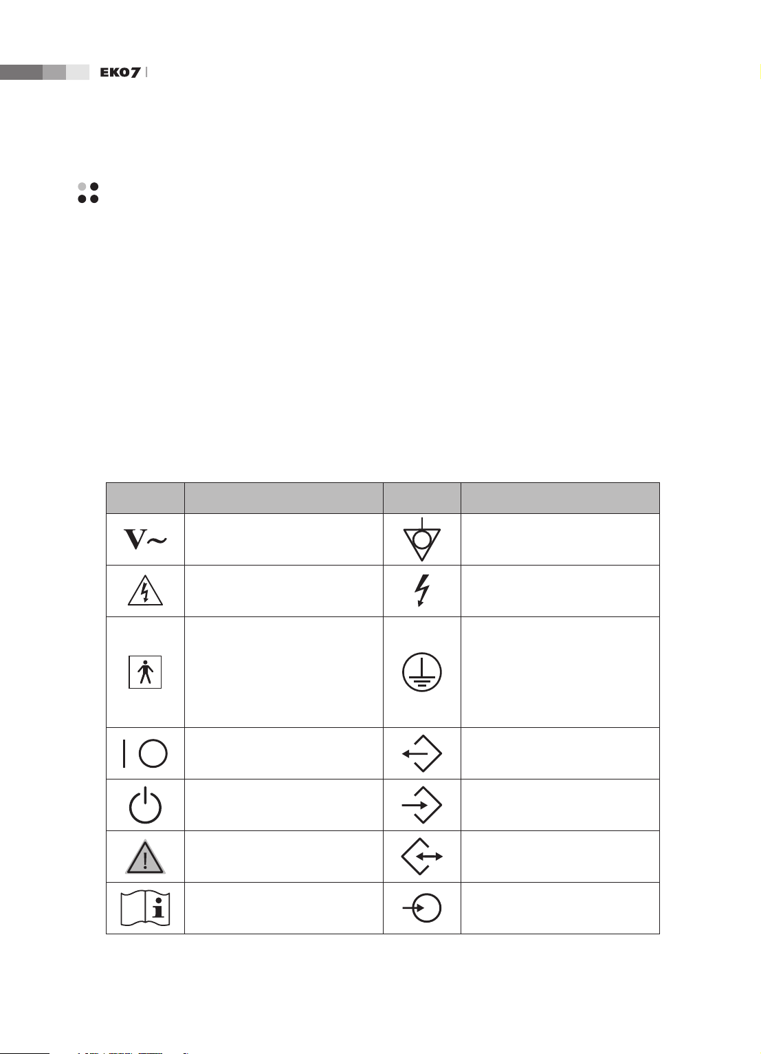
Safety Symbols
The International Electro Technical Commission (IEC) has established a set of symbols for medical
electronic equipment, which classify a connection or warn of potential hazards. The classications and
symbols are shown below.
Symbols Description Symbols Description
AC (alternating current) voltage
source
Indicates a caution for risk of
electric shock.
Isolated patient connection (Type
BF applied part).
Power switch (Supplies/cuts the
power for product)
Identies an equipotential ground.
Indicates dangerous voltages over
1000V AC or over 1500V DC.
Identies the point where the
system safety ground is fastened
to the chassis. Protective earth
connected to conductive parts
of Class I equipment for safety
purposes.
Data Output port
1-
On/Off button Data Input port
Caution Data Input/Output port
Refer to the operation manual
Left and right Audio / Video input
4
Page 19
Chapter 1 Safety
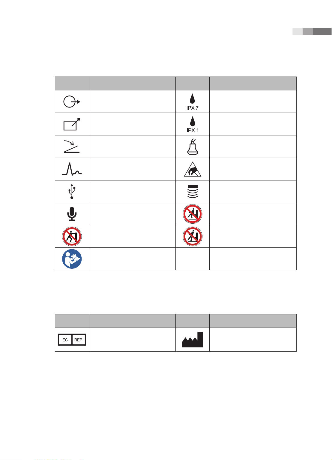
Symbols Description Symbols Description
Left and right Audio / Video output
Remote print output Protection against dripping water.
Foot switch connector Probe connector
ECG connector
USB connector Probe connector
Microphone connector
Do not push the product Do not lean against the product
Follow the operation manual
Protection against the effects of
immersion.
ESD (Electrostatic discharge)
caution symbol
Do not sit on control panel
Symbols
Symbols Description Symbols Description
Authorized Representative In The
European Community
Manufacture :
SAMSUNG MEDISON CO., LTD
1 -
5
Page 20
Operation Manual
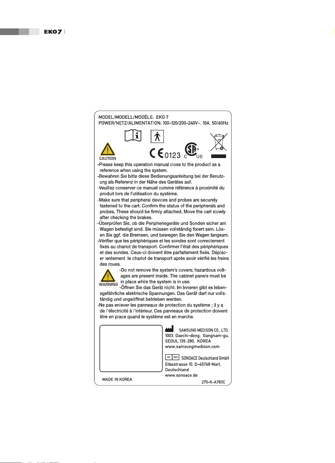
Labels
To protect the system, you may see ‘Warning’ or ‘Caution’ marked on the surface of the product.
1-
[Label 1. ID label]
6
Page 21
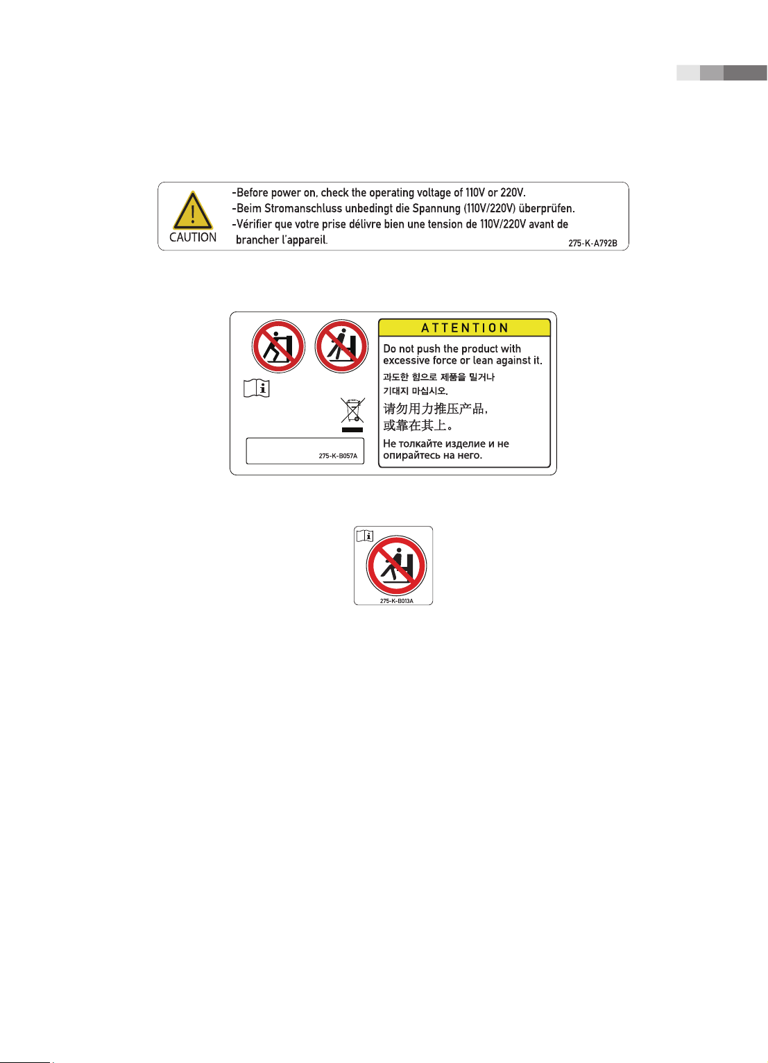
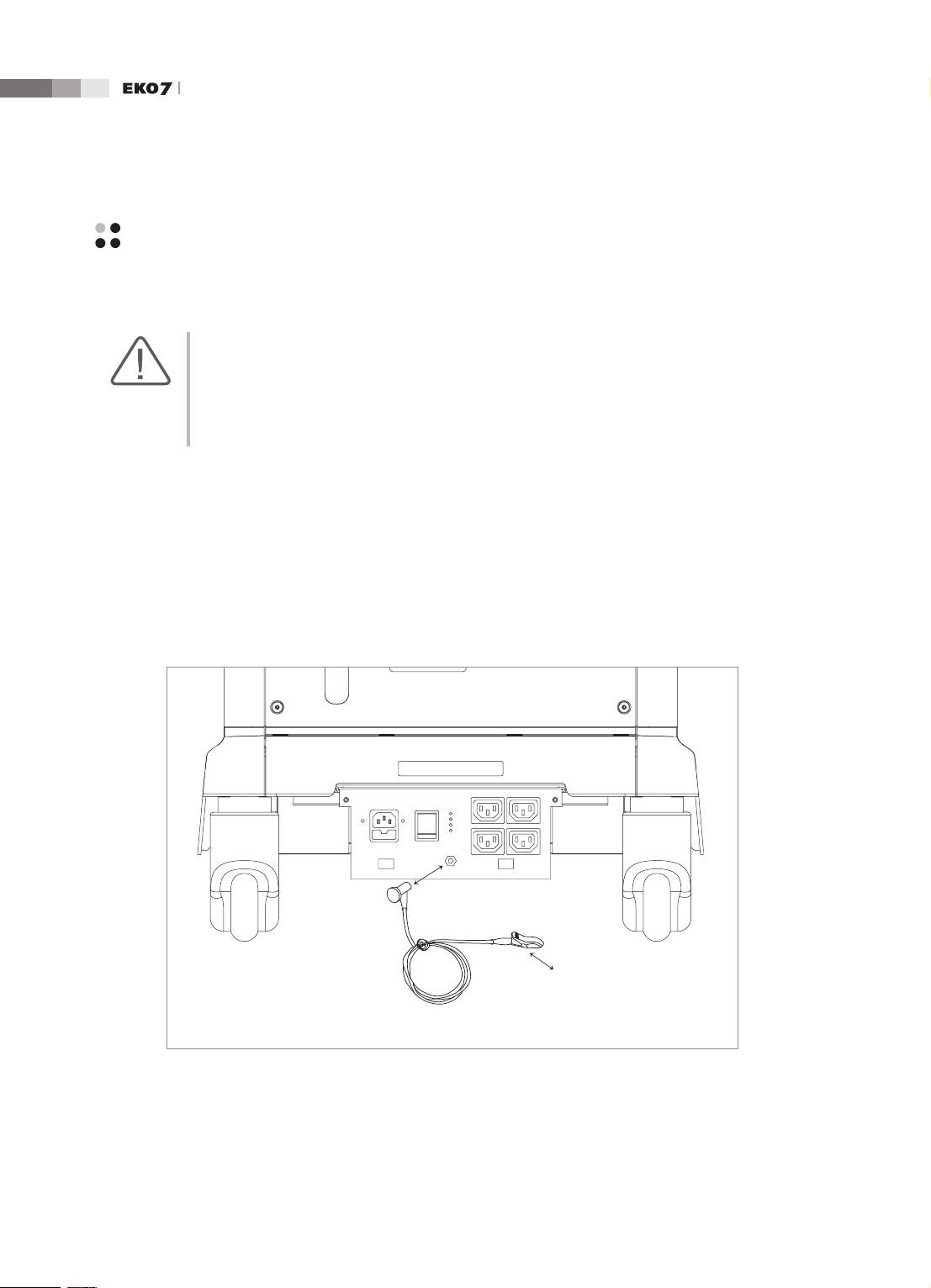
[Label 2. Marked below OUTLET]
Chapter 1 Safety
[Label 3. Safety note for “TIP-OVER” Precaution]
[Label 4. Prohibition of seating on Control panel]
1 -
7
Page 22
Operation Manual
Electrical Safety
This equipment has been veried as a Class I device with Type BF applied parts.
CAUTION:
As for US requirement, the LEAKAGE CURRENT might be measured from a center-tapped circuit
when the equipment connects in the United States to 240V supply system.
To help assure grounding reliability, connect to a “hospital grade” or “hospital only” grounded
power outlet.
Prevention of Electric Shock
In a hospital, dangerous currents are due to the potential differences between connected equipment
and touchable conducting parts found in medical rooms. The solution to the problem is consistent
equipotential bonding. Medical equipment is connected with connecting leads made up of angled
sockets to the equipotential bonding network in medical rooms.
1-
Equipotential Terminal
Connection Lead
(Socket)
Earth in Medical Room
Equipotential Connector
[Figure 1.1 Equipotential bonding]
8
Page 23

Chapter 1 Safety
Additional equipment connected to medical electrical equipment must comply with the respective IEC
or ISO standards (e.g. IEC 60950 for data processing equipment). Furthermore all congurations shall
comply with the requirements for medical electrical systems (see IEC 60601-1-1 or clause 16 of the
3 Ed. of IEC 60601-1, respectively). Anybody connecting additional equipment to medical electrical
equipment congures a medical system and is therefore responsible that the system complies with the
requirements for medical electrical systems. Attention is drawn to the fact that local laws take priority
over the above-mentioned requirements. If in doubt, consult your local representative or the technical
service department.
WARNING:
Electric shock may exist result if this system, including and all of its externally mounted recording
and monitoring devices, is not properly grounded.
Do not remove the covers on the system; hazardous voltages are present inside. Cabinet panels
must be in place while the system is in use. All internal adjustments and replacements must be
made by a qualified MEDISON Customer Service Department.
Check the face, housing, and cable before use. Do not use and disconnect the power source, if
the face is cracked, chipped, or torn, the housing is damaged, or if the cable is abraded.
Always disconnect the system from the wall outlet prior to cleaning the system.
All patient contact devices, such as probes and ECG leads, must be removed from the patient
prior to application of a high voltage defibrillation pulse.
Never use the product in proximity to any flammable anesthetic gases (N2O) or oxidizing gases.
There is a risk of explosion.
Avoid places where the system is likely to be difficult to operate the disconnection device.
CAUTION:
The system has been designed for 100-120VAC and 200-240VAC; you should select the input
voltage of printer and VCR. Prior to connecting a peripheral power cord, verify that the voltage
indicated on the power cord matches the voltage rating of the peripheral device.
An isolation transformer protects the system from power surges. The isolation transformer
continues to operate when the system is in standby.
Do not immerse the cable in liquids. Cables are not waterproof.
The auxiliary socket outlets installed on this system are rated 100-120V and 200-240V with
maximum total load of 200W. Use these outlets only for supplying power to equipment that is
intended to be part of the ultrasound system. Do not connect additional multiple-socket outlets
or extension cords to the system.
Do not touch SIP/SOP and the patient simultaneously. There is a risk of electric shock from
leakage current.
1 -
9
Page 24

Operation Manual
ECG-Related Information
WARNING:
This device is not intended to provide a primary ECG monitoring function, and therefore does
not have means of indicating an inoperative electrocardiograph.
Do not use ECG electrodes of HF surgical equipment. Any malfunctions in the HF surgical
equipment may result in burns to the patient.
Do not use ECG electrodes during cardiac pacemaker procedures or other electrical stimulators.
Do not use ECG leads and electrodes in an operating room.
ESD
Electrostatic discharge (ESD), commonly referred to as a static shock, is a naturally occurring
phenomenon. ESD is most prevalent during conditions of low humidity, which can be caused by
heating or air conditioning. During low humidity conditions, electrical charges naturally build up on
individuals, creating static electricity. An ESD occurs when an individual with an electrical energy
build-up comes in contact with conductive objects such as metal doorknobs, le cabinets, computer
equipment, and even other individuals. The static shock or ESD is a discharge of the electrical energy
build-up from a charged individual to a lesser or non-charged individual or object.
1-
10
CAUTION:
The level of electrical energy discharged from a system user or patient to an ultrasound system
can be significant enough to cause damage to the system or probes.
Always perform the pre-ESD preventive procedures before using connectors marked with the
ESD warning label.
Apply anti-static spray on carpets or linoleum.
−
Use anti-static mats.
−
Ground the product to the patient table or bed.
−
It is highly recommended that the user be given training on ESD-related warning symbols and
preventive procedures.
Page 25

Chapter 1 Safety
EMI
Although this system has been manufactured in compliance with existing EMI (ElectroMagnetic
Interference) requirements, use of this system in the presence of an electromagnetic eld can cause
momentary degradation of the ultrasound image.
If this occurs often, MEDISON suggests a review of the environment in which the system is being
used, to identify possible sources of radiated emissions. These emissions could be from other
electrical devices used within the same room or an adjacent room. Communication devices such as
cellular phones and pagers can cause these emissions. The existence of radios, TVs, or microwave
transmission equipment nearby can also cause interference.
CAUTION: In cases where EMI is causing disturbances, it may be necessary to relocate this system.
EMC
The testing for EMC(Electromagnetic Compatibility) of this system has been performed according
to the international standard for EMC with medical devices (IEC60601-1-2). This IEC standard was
adopted in Europe as the European norm (EN60601-1-2).
Guidance and manufacturer’s declaration - electromagnetic emission
This product is intended for use in the electromagnetic environment specied below. The customer
or the user of this product should assure that it is used in such an environment.
Emission test Compliance Electromagnetic environment -guidance
The Ultrasound System uses RF energy only for its
RF Emission
CISPR 11
RF Emission
CISPR 11
Harmonic Emission
IEC 61000-3-2
Flicker Emission
IEC 61000-3-3
Group 1
Class B
Class A
Complies
internal function. Therefore, its RF emissions are very
low and are not likely to cause any interference in nearby
electronic equipment.
The Ultrasound System is suitable for use in all
establishments, including domestic establishments and
those directly connected to the public low-voltage power
supply network that supplies building used for domestic
purpose.
1 -
11
Page 26
Operation Manual
Approved Cables, Transducers and Accessories for EMC
■
Approved Cable for Electromagnetic Compliance
Cables connected to this product may affect its emissions;
Use only the cable types and lengths listed below table.
Cable Type Length
VGA Shielded Normal
RS232C Shielded Normal
USB Shielded Normal
LAN(RJ45) Twisted pair Any
S-Video Shielded Normal
Foot Switch Shielded 2.5m
B/W Printer Unshielded Coaxial Normal
MIC Unshielded Any
Printer Remote Unshielded Any
Audio R.L Shielded Normal
VHS Shielded Normal
ECG AUX input Shielded < 3m
Parallel Shielded Normal
■
Approved Transducer for Electromagnetic Compliance
The probe listed in ‘Chapter 9. Probes’ when used with this product, have been tested to comply
with the group1 class B emission as required by International Standard CISPR 11.
■
Approved Accessories for Electromagnetic Compliance
Accessories used with this product may effect its emissions.
CAUTION: When connecting other customer-supplied accessories to the system, such as a remote
printer or VCR, it is the user’s responsibility to ensure the electromagnetic compatibility of the
system. Use only CISPR 11 or CISPR 22, CLASS B compliant devices.
WARNING: The use of cables, transducers, and accessories other than those specified may result in
increased emission or decreased Immunity of the Ultrasound System.
1-
12
Page 27

Chapter 1 Safety
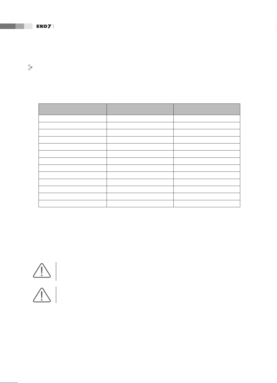
Immunity test IEC 60601 Test level Compliance level
Electrotatic
discharge (ESD)
IEC 61000-4-2
Electrical fast
transient/burst
IEC 61000-4-4
Surge
IEC 61000-4-5
Voltage
dips, short
interruptions and
voltage variations
on power supply
input lines
IEC 61000-4-11
±6KV Contact
±8KV air
±2KV
for power supply lines
±1KV
for input/output lines
±1KV differential mode
±2KV common mode
<5% Uт for 0.5cycle
(>95% dip in Uт)
40% Uт for 5 cycle
(60% dip in Uт )
70% Uт for 25 cycle
(30% dip in Uт)
<5% Uт for 5 s
(<95% dip in Uт )
±6KV Contact
±8KV air
±2KV
for power supply lines
±1KV
for input/output lines
±1KV differential mode
±2KV common mode
<5% Uт for 0.5cycle
(>95% dip in Uт)
40% Uт for 5 cycle
(60% dip in Uт )
70% Uт for 25 cycle
(30% dip in Uт)
<5% Uт for 5 s
(<95% dip in Uт )
Electromagnetic
environment -guidance
Floors should be wood,
concrete or ceramic tile.
If oors are covered with
synthetic material, the relative humidity should be at
least 30%.
Mains power quality should
be that of a typical commercial or hospital environment.
Mains power quality should
be that of a typical commercial or hospital environment.
Mains power quality
should be that of a typical
commer-cial or hospital
environment. If the user
of this product requires
continued operation during
power mains interrup-tions,
it is recommended that this
product be powered from
an uninterruptible power
supply or a battery.
Power frequency
(50/60Hz)
magnetic eld
3 A/m 3 A/m
IEC 61000-4-8
NOTE Uт is the a.c. mains voltage prior to application of the test level.
Power frequency magnetic
elds should be at levels
characteristic of a typical
location in a typical
commer-cial or hospital
environment.
1 -
13
Page 28
Operation Manual
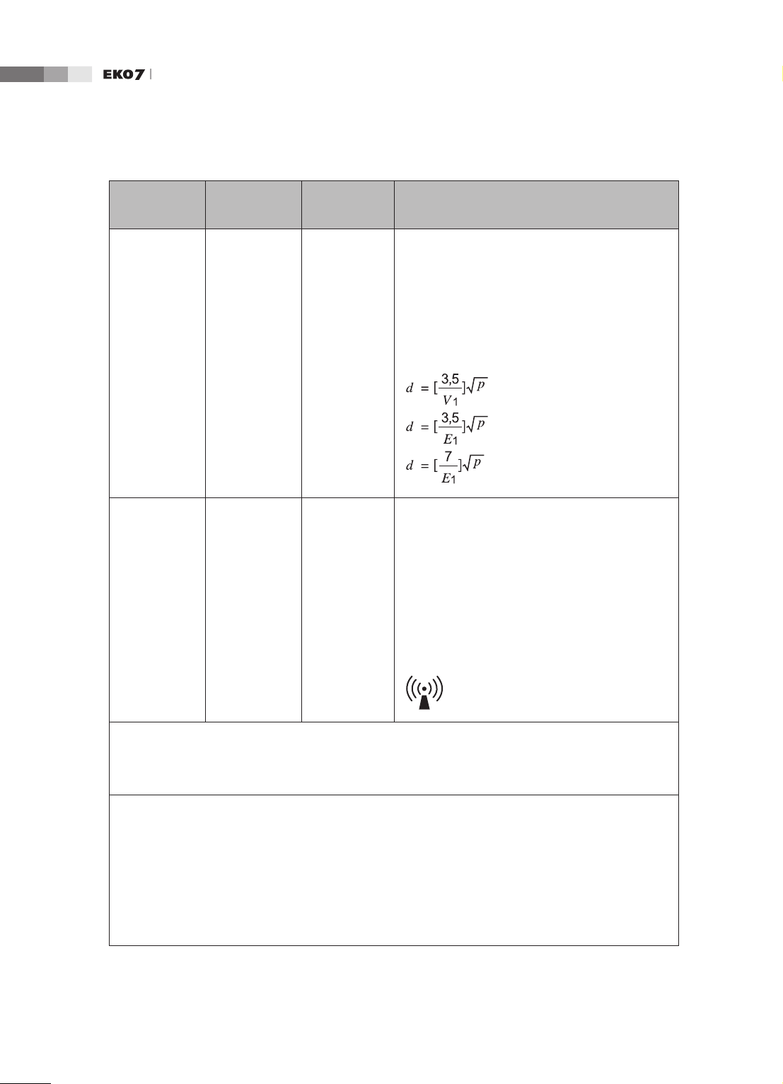
Immunity test
Conducted
RF
IEC 61000-46
Radiated RF
IEC 61000-43
IEC 60601
Test level
3 Vrms
150 kHz
to 80MHz
3 V/m
80 MHz
to 2.5GHz
Compliance
level
0.01V
3V/m
Electromagnetic
environment - guidance
Portable and mobile RF communications
equipment should be used no closer to any part
of the Ultrasound System, including cables, than
the recommended separation distance calculated
from the equation applicable to the frequency of
the transmitter.
Recommended separation distance
80MHz to 800MHZ
800MHz to 2.5GHz
where P is the maximum output power rating
of the transmitter in watts (W) according to the
transmitter manufacturer and d is the recommended separation distance in meters (m).
Field strengths from xed RF transmitters, as
determined by an electromagnetic site survey,
should be less than the compliance level in each
frequency range.
b
a
Interference may occur in the vicinity of equipment
marked with the following symbol :
NOTE 1) At 80MHz and 800MHz, the higher frequency range applies.
NOTE 2) These guidelines may not apply in all situations. Electromagnetic propagation is affected by
absorption and reection from structures, objects and people.
a
Field strengths from xed transmitters, such as base stations for radio (cellular/cordless) telephones
and land mobile radios, amateur radio, AM and FM radio broadcast and TV broadcast cannot be
predicted theoretically with accuracy. To assess the electromagnetic environment due to xed RF
transmitters, an electromagnetic site survey should be considered. If the measured eld strength in the
location in which the Ultrasound System is used exceeds the applicable RF compliance level above,
the Ultrasound System should be observed to verify normal operation. If abnormal performance is
observed, additional measures may be necessary, such as re-orienting or relocating the Ultrasound
System or using a shielded location with a higher RF shielding effectiveness and lter attenuation.
b
Over the frequency range 150kHz to 80MHz, eld strengths should be less than [V1] V/m.
1-
14
Page 29
Chapter 1 Safety
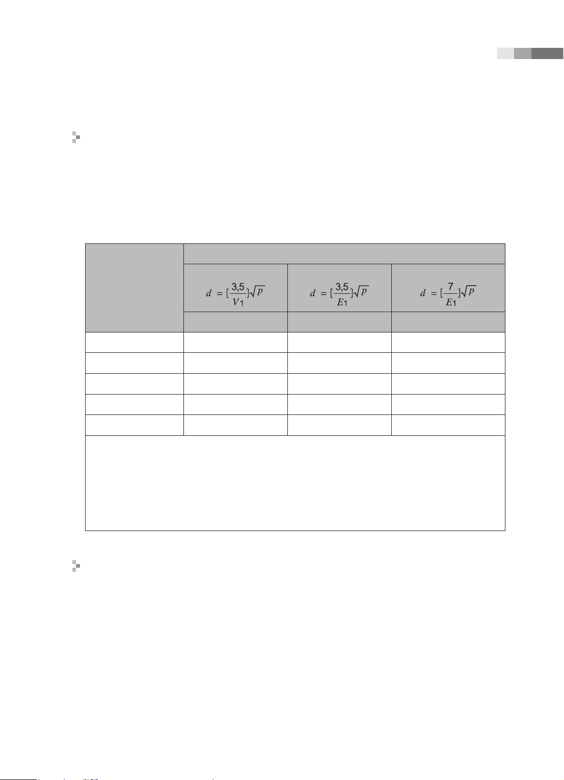
Recommended separation distances between portable and mobile RF
communications equipment and the EKO 7
This product is intended for use in an electromagnetic environment in which radiated RF
disturbances are controlled. The customer or the user of this product can help Prevent
electromagnetic interference by maintaining a minimum distance between portable and mobile RF
communications equipment (transmitters) and this product as recommended below, according to
the maximum output power of the communications equipment.
Separation distance according to frequency of transmitter [m]
Rated maximum
output power of
transmitter
[W]
0.01 35.00 0.11 0.23
0.1 110.68 0.36 0.73
1 350.00 1.16 2.33
10 1106.80 3.68 7.37
100 3500.00 11.66 23.33
For transmitters rated at a maximum output power not listed above, the recommended separation distance
d in meters (m) can be estimated using the equation applicable to the frequency of the transmitter,
where p is the maximum output power rating of the transmitter in watts (W) according to the transmitter
manufacturer.
NOTE 1) At 80MHz and 800MHz, the separation distance for the higher frequency range applies.
NOTE 2) These guidelines may not apply in all situations. Electromagnetic propagation is affected by
absorption and reection from structures, objects and people.
Electromagnetic environment – guidance
150kHz to 80MHz
V1=0.01Vrms E1=3 V/m E1=3V/m
80MHz to 800MHz
800MHz to 2.5GHz
The Ultrasound System must be used only in a shielded location with a minimum RF shielding
effectiveness and, for each cable that enters the shielded location. Field strengths outside the
shielded location from fixed RF transmitters, as determined by an electromagnetic site survey,
should be less than 3V/m.
It is essential that the actual shielding effectiveness and lter attenuation of the shielded location be
veried to assure that they meet the minimum specication.
1 -
15
Page 30

Operation Manual
CAUTION: If the system is connected to other customer-supplied equipment, such as a local area
network (LAN) or a remote printer, Medison cannot guarantee that the remote equipment will work
correctly in the presence of electromagnetic phenomena.
Avoiding Electromagnetic Interference
Typical interference on Ultrasound Imaging Systems varies depending on Electromagnetic
phenomena. Please refer to following table:
Imaging Mode ESD
2D
Change of operating
mode, system settings,
M
or system reset.
Brief ashes in the
displayed or recorded
image.
Color
Doppler
1
RF
2
Power Line
3
For sector imaging probes,
white radial bands or
ashes in the centerlines of
the image.
For linear imaging
probes, white vertical
White dots, dashes, diagonal
lines, or diagonal lines near
the center of the image.
bands, sometimes more
pronounced on the sides of
the image.
Increase in the image
background noise or white
M mode lines.
Color ashes, radial or
vertical bands, increase
in background noise, or
changes in color image.
Horizontal lines in the
spectral display or tones,
abnormal noise in the audio,
or both.
White dots, dashes, diagonal
lines, or increase in image
background noise
Color ashes, dots, dashes,
or changes in the color noise
level.
Vertical lines in the spectral
display, popping type noise in
the audio, or both.
ESD caused by discharging of electric charge build-up on insulated surfaces or persons.
RF energy from RF transmitting equipment such as portable phones, hand-held radios, wireless devices,
commercial radio and TV, and so on.
Conducted interference on powerlines or connected cables caused by other equipment, such as switching
power supplies, electrical controls, and natural phenomena such as lightning.
A medical device can either generate or receive electromagnetic interference. The EMC standards
describe tests for both emitted and received interference.
Medison Ultrasound System do not generate interference in excess of the referenced standards.
An Ultrasound System is designed to receive signals at radio frequency and is therefore susceptible
1-
16
Page 31

Chapter 1 Safety
to interference generated by RF energy sources. Examples of other source of interference are
medical device, information technology products, and radio and television transmission towers.
Tracing the source of radiated interference can be a difcult task. Customers should consider the
following in an attempt to locate the source:
▶
Is the interference intermittent or constant?
▶
Does the interference show up only with one transducers operating at the same frequency or
with several transducer?
▶
Do two different transducer operating at the same frequency have the same problem?
▶
Is the interference present if the system is moved to a different location in the facility?
▶
The answers to these questions will help determine if the problem reside with the system or the
scanning environment. After you answer the question, contact your local MEDISON customer
service department.
1 -
17
Page 32

Operation Manual
Mechanical Safety
Moving the Equipment
WARNING: The product weighs more than 100kg. Be extra careful when transporting it. Careless
transportation of the product may result in product damage or personal injury.
■
Before transporting the product, check that the brakes on wheels are unlocked. Also, make
sure to retract the monitor arm completely so that it is secured in a stationary position.
■
Always use the handles at the back of the console and move the product slowly.
This product is designed to resist shocks. However, excessive shock, for example if the product
falls over, may cause serious damage.
If the system operates abnormally after repositioning, please contact the MEDISON Customer
Service Department.
The Brakes
Brakes are mounted to wheels of the console. To lock the brakes, press the top part of the brake
with your foot. To unlock them, press the part labelled OFF at the bottom of the brake with your
foot.
You can use the brakes to control the movement of the product. We recommend that you lock the
brakes when using the product.
Precautions on Ramps
Always make sure that the control panel is facing the direction of movement.
WARNING: Be aware of the castors, especially when moving the system. MEDISON recommends
that you exercise caution when moving the product up or down ramps.
When moving the product down a ramp or resting it temporarily on a ramp, the product may tilt
over even with the brakes on depending on the direction of the product. Do not rest the product on
ramps.
1-
18
Page 33

Chapter 1 Safety
Safety Note
CAUTION:
Never attempt to modify the product in any way.
Check the operational safety when using the product after a prolonged break in service.
Make sure that other objects, such as metal pieces, do not enter the system.
Do not block the ventilation slots.
To prevent damage to the power cord, be sure to grip the plug head – not the cord – when
unplugging.
Excessive bending or twisting of cables on patient-applied parts may cause failure or intermittent
operation of the system.
Improper cleaning or sterilization of a patient-applied part may cause permanent damage.
Please refer to “Chapter 8. Maintenance” for detailed information on protecting, cleaning and
disinfecting the equipment.
Safety Note for Monitor
When adjusting the height or position of the monitor, be careful of the space in the middle of the
monitor arm. Having your ngers or other body parts caught in it may result in injury.
[Figure 1.2 Safety note for monitor]
1 -
19
Page 34

Operation Manual
Caution for Using Control Panel
CAUTION:
Do not press on the control panel with excessive force or lean against it.
Do not sit on the control panel or apply too much force to it.
When adjusting the height or position of the control panel, be careful not to leave your ngers or
hand in area between the control panel and the lift - they may get trapped and hurt.
[Figure 1.3 Safety note for control panel]
1-
20
Page 35

Chapter 1 Safety
Biological Safety
For more safety information on probes and biopsy, please refer to Chapter 9 'Probes.’
WARNING:
Ultrasound waves may have damaging effects on cells and, therefore, may be harmful to the
patient. If there is no medical benefit, minimize the exposure time and maintain the ultrasound
wave output level at low. Please refer to the ALARA principle.
Do not use the system if an error message appears on the video display indicating that a
hazardous condition exists. Note the error code, turn off the power to the system, and call your
local MEDISON Customer Service Department.
Do not use a system that exhibits erratic or inconsistent updating. Discontinuities in the
scanning sequence are indicative of a hardware failure that should be corrected before use.
The system limits the maximum contact temperature to 43 degree Celsius, and the ultrasonic
waves output observes American FDA regulations.
ALARA Principle
Guidance for the use of diagnostic ultrasound is defined by the “as low as reasonably achievable”
(ALARA) principle. The decision as to what is reasonable has been left to the judgment and insight of
qualied personnel. No set of rules can be formulated that would be sufciently complete to dictate the
correct response for every circumstance. By keeping ultrasound exposure as low as possible, while
obtaining diagnostic images, users can minimize ultrasonic bioeffects.
Since the threshold for diagnostic ultrasound bioeffects is undetermined, it is the sonographer’s
responsibility to control the total energy transmitted into the patient. The sonographer must reconcile
exposure time with diagnostic image quality. To ensure diagnostic image quality and limit exposure
time, the ultrasound system provides controls that can be manipulated during the exam to optimize the
results of the exam.
The ability of the user to abide by the ALARA principle is important. Advances in diagnostic ultrasound
not only in the technology but also in the applications of the technology, have resulted in the need
for more and better information to guide the user. The output indices are designed to provide that
important information
There are a number of variables, which affect the way in which the output display indices can be used
to implement the ALARA principle. These variables include mass, body size, location of the bone
relative to the focal point, attenuation in the body, and ultrasound exposure time. Exposure time is an
especially useful variable, because the user controls it. The ability to limit the index values over time
support the ALARA principle.
1 -
21
Page 36

Operation Manual
Applying ALARA
The system-imaging mode used depends upon the information needed. 2D-mode and M-mode
imaging provide anatomical information, while Doppler, Power, and Color imaging provide
information about blood flow. Scanned modes, like 2D-mode, Power, or Color, disperse or
scatter the ultrasonic energy over an area, while an unscanned mode, like M-mode or Doppler,
concentrates ultrasonic energy. Understanding the nature of the imaging mode being used allows
the sonographer to apply the ALARA principle with informed judgment. The probe frequency,
system set-up values, scanning techniques, and operator experience aid the sonographer in
meeting the denition of the ALARA principle.
The decision as to the amount of acoustic output is, in the nal analysis, up to the system operator.
This decision must be based on the following factors: type of patient, type of exam, patient history,
ease or difculty of obtaining diagnostically useful information, and the potential localized heating
of the patient due to probe surface temperatures. Prudent use of the system occurs when patient
exposure is limited to the lowest index reading for the shortest amount of time necessary to achieve
acceptable diagnostic results.
Although a high index reading does not mean that a bioeffect is actually occurring, a high index
reading should be taken seriously. Every effort should be made to reduce the possible effects of a
high index reading. Limiting exposure time is an effective way to accomplish this goal.
There are several system controls that the operator can use to adjust the image quality and limit
the acoustic intensity. These controls are related to the techniques that an operator might use
to implement ALARA. These controls can be divided into three categories: direct, indirect, and
receiver control.
Direct Controls
Application selection and the output intensity control directly affect acoustic intensity. There are
different ranges of allowable intensity or output based on your selection. Selecting the correct
range of acoustic intensity for the application is one of the rst things required during any exam. For
example, peripheral vascular intensity levels are not recommended for fetal exams. Some systems
automatically select the proper range for a particular procedure, while others require manual
selection. Ultimately, the user bears the responsibility for proper clinical use. The MEDISON system
provides both automatic and user-denable settings.
Output has direct impact on acoustic intensity. Once the application has been established, the
output control can be used to increase or decrease the intensity output. The output control allows
you to select intensity levels less than the dened maximum. Prudent use dictates that you select
the lowest output intensity consistent with good image quality.
1-
22
Page 37

Chapter 1 Safety
Indirect Controls
The indirect controls are those that have an indirect effect on acoustic intensity. These controls
affect imaging mode, pulse repetition frequency, focus depth, pulse length, and probe selection.
The choice of imaging mode determines the nature of the ultrasound beam. 2D-mode is a scanning
mode, Doppler is a stationary or unscanned mode. A stationary ultrasound beam concentrates
energy on a single location. A moving or scanned ultrasound beam disperses the energy over a
wide area and the beam is only concentrated on a given area for a fraction of the time necessary in
unscanned mode.
Pulse repetition frequency or rate refers to the number of ultrasound bursts of energy over a
specic period of time. The higher the pulse repetition frequency, the more pulses of energy in a
given period of time. Several controls affect pulse repetition frequency: focal depth, display depth,
sample volume depth, color sensitivity, number of focal zones, and sector width controls.
Focus of the ultrasound beam affects the image resolution. To maintain or increase resolution
at a different focus requires a variation in output over the focal zone. This variation of output is a
function of system optimization. Different exams require different focal depths. Setting the focus to
the proper depth improves the resolution of the structure of interest.
Pulse length is the time during which the ultrasonic burst is turned on. The longer the pulse, the
greater the time-average intensity value. The greater the time-average intensity, the greater the
likelihood of temperature increase and cavitations. Pulse length or burst length or pulse duration is
the output pulse duration in pulsed Doppler. Increasing the Doppler sample volume increases the
pulse length.
Probe selection affects intensity indirectly. Tissue attenuation changes with frequency. The higher
the probe operating frequency, the greater the attenuation of the ultrasonic energy. Higher probe
operating frequencies require higher output intensity to scan at a deeper depth. To scan deeper at
the same output intensity, a lower probe frequency is required. Using more gain and output beyond
a point, without corresponding increases in image quality, can mean that a lower frequency probe
is needed.
■
Receiver Controls
Receiver controls are used by the operator to improve image quality. These controls have no
effect on output. Receiver controls only affect how the ultrasound echo is received. These
controls include gain, TGC, dynamic range, and image processing. The important thing to
remember, relative to output, is that receiver controls should be optimized before increasing
output. For example; before increasing output, optimize gain to improve image quality.
1 -
23
Page 38

Operation Manual
Additional Considerations
Ensure that scanning time is kept to a minimum, and ensure that only medically required scanning
is performed. Never compromise quality by rushing through an exam. A poor exam will require
a follow-up, which ultimately increases the time. Diagnostic ultrasound is an important tool in
medicine, and, like any tool, should be used efciently and effectively.
Output Display Features
The system output display comprises two basic indices: a mechanical index and a thermal index.
The thermal index consists of the following indices: soft tissue (TIs), bone (TIb) and cranial bone
(TIc). One of these three thermal indices will be displayed at all times. Which one depends upon
the system preset or user choice, depending upon the application at hand.
The mechanical index is continuously displayed over the range of 0.0 to 1.9, in increments of 0.1.
The thermal index consists of the three indices, and only one of these is displayed at any one time.
Each probe application has a default selection that is appropriate for that combination. The TIb or
TIs is continuously displayed over the range of 0.0 to maximum output, based on the probe and
application, in increments of 0.1.
The application-specic nature of the default setting is also an important factor of index behavior.
A default setting is a system control state which is preset by the manufacturer or the operator.
The system has default index settings for the probe application. The default settings are invoked
automatically by the ultrasound system when power is turned on, new patient data is entered into
the system database, or a change in application takes place.
The decision as to which of the three thermal indices to display should be based on the following criteria:
Appropriate index for the application: TIs is used for imaging soft tissue; and TIb for a focus at or
near bone. Some factors might create articially high or low thermal index readings e.g. presence
of uid or bone, or the ow of blood. A highly attenuating tissue path, for example, will cause the
potential for local zone heating to be less than the thermal index displays.
Scanned modes versus unscanned modes of operation affect the thermal index. For scanned
modes, heating tends to be near the surface; for unscanned modes, the potential for heating tends
to be deeper in the focal zone.
Always limit ultrasound exposure time. Do not rush the exam. Ensure that the indices are kept to a
minimum and that exposure time is limited without compromising diagnostic sensitivity.
1-
24
Page 39

Chapter 1 Safety
■
Mechanical Index (MI) Display
Mechanical bioeffects are threshold phenomena that occur when a certain level of output
is exceeded. The threshold level varies, however, with the type of tissue. The potential for
mechanical bioeffects varies with peak pressure and ultrasound frequency. The MI accounts for
these two factors. The higher the MI value, the greater the likelihood of mechanical bioeffects
occurring but there is no specic MI value that means that a mechanical effect will actually occur.
The MI should be used as a guide for implementing the ALARA principle.
■
Thermal Index (TI) Display
The TI informs the user about the potential for temperature increase occuring at the body surface,
within body tissue, or at the point of focus of the ultrasound beam on bone. The TI is an estimate
of the temperature increase in specic body tissues. The actual amount of any temperature rise
is inuenced by factors such as tissue type, vascularity, and mode of operation etc. The TI should
be used as a guide for implementing the ALARA principle.
The bone thermal index (TIb) informs the user about potential heating at or near the focus after
the ultrasound beam has passed through soft tissue or uid, for example, at or near second or
third trimester fetal bone.
The cranial bone thermal index (TIc) informs the user about the potential heating of bone at or
near the surface, for example, cranial bone.
The soft tissue thermal index (TIs) informs the user about the potential for heating within soft
homogeneous tissue.
You can select either TIs or TIb using the TIs/TIb selection on the Miscellaneous system setups.
TIc is displayed when you select a trans-cranial application.
■
Mechanical and Thermal indices Display Precision and Accuracy
The Mechanical and Thermal Indices on the system are precise to 0.1 units.
The MI and TI display accuracy estimates for the system are given in the Acoustic Output Tables
manual. These accuracy estimates are based on the variability range of probes and systems,
inherent acoustic output modeling errors and measurement variability, as described below.
The displayed values should be interpreted as relative information to help the system operator
achieve the ALARA principle through prudent use of the system. The values should not be
interpreted as actual physical values investigated tissue or organs. The initial data that is used
to support the output display is derived from laboratory measurements based on the AIUM
measurement standard. The measurements are then put into algorithms for calculating the
displayed output values.
1 -
25
Page 40

Operation Manual
Many of the assumptions used in the process of measurement and calculation are conservative
in nature. Over-estimation of actual in situ exposure, for the vast majority of tissue paths, is built
into the measurement and calculation process. For example:
The measured water tank values are de-rated using a conservative, industry standard,
attenuation coefcient of 0.3dB/cm-MHz.
Conservative values for tissue characteristics were selected for use in the TI models.
Conservative values for tissue or bone absorption rates, blood perfusion rates, blood heat
capacity, and tissue thermal conductivity were selected.
Steady state temperature rise is assumed in the industry standard TI models, and the assumption is
made that the ultrasound probe is held steady in one position long enough for steady state to be reached.
A number of factors are considered when estimating the accuracy of display values: hardware
variations, algorithm accuracy estimation and measurement variability. Variability among probes
and systems is a signicant factor. Probe variability results from piezoelectric crystal efciencies,
process-related impedance differences, and sensitive lens focusing parameter variations.
Differences in the system pulse voltage control and efciencies are also a contributor to variability.
There are inherent uncertainties in the algorithms used for estimating acoustic output values over
the range of possible system operating conditions and pulse voltages. Inaccuracies in laboratory
measurements are related to differences in hydrophone calibration and performance, positioning,
alignment and digitization tolerances, and variability among test operators.
The conservative assumptions of the output estimation algorithms of linear propagation, at all
depths, through a 0.3dB/cm-MHz attenuated medium are not taken into account in calculation of
the accuracy estimate displayed. Neither linear propagation, nor uniform attenuation at the 0.3dB/
cm-MHz rate, occur in water tank measurements or in most tissue paths in the body. In the body,
different tissues and organs have dissimilar attenuation characteristics. In water, there is almost
no attenuation. In the body, and particularly in water tank measurements, non-linear propagation
and saturation losses occur as pulse voltages increase.
The display accuracy estimates take into account the variability ranges of probes and systems,
inherent acoustic output modeling errors, and measurement variability. Display accuracy
estimates are not based on errors in, or caused by measuring according to, the AIUM
measurement standards. They are also independent of the effects of non-linear loss on the
measured values.
1-
26
Page 41

Chapter 1 Safety
Control Effects - Control affecting the indices
As various system controls are adjusted, the TI and MI values may change. This will be most
apparent as the POWER control is adjusted; however, other system controls will affect the onscreen output values.
■
Power
Power controls the system acoustic output. Two real-time output values are on the screen: a TI
and a MI. They change as the system responds to POWER adjustments.
In combined modes, such as simultaneous Color, 2D-mode and pulsed Doppler, the individual
modes each add to the total TI. One mode will be the dominant contributor to this total. The
displayed MI will be from the mode with the largest peak pressure.
2D-mode Controls
■
2D-mode size
Narrowing the sector angle may increase the frame rate. This action will increase the TI. Pulse
voltage may be automatically adjusted down with software controls to keep the TI below the
system maximums. A decrease in pulse voltage will decrease MI.
■
Zoom
Increasing the zoom magnication may increase frame rate. This action will increase the TI. The
number of focal zones may also increase automatically to improve resolution. This action may
change MI since the peak intensity can occur at a different depth.
■
Persistence
A lower persistence will decrease the TI. Pulse voltage may be automatically increased. An
increase in pulse voltage will increase MI.
■
Focal no.
More focal zones may change both the TI and MI by changing frame rate or focal depth
automatically. Lower frame rates decrease the TI. MI displayed will correspond to the zone with
the largest peak intensity.
■
Focus
Changing the focal depth will change the MI. Generally, higher MI values will occur when the
focal depth is near the natural focus of the transducer.
1 -
27
Page 42

Operation Manual
Color and Power Controls
■
Color Sensitivity
Increasing the color sensitivity may increase the TI. More time is spent scanning for color images.
Color pulses are the dominant pulse type in this mode.
■
Color Sector Width
Narrower color sector width will increase color frame rate and the TI will increase. The system
may automatically decrease pulse voltage to stay below the system maximum. A decrease in
pulse voltage will decrease the MI. If pulsed Doppler is also enabled then pulsed Doppler will
remain the dominant mode and the TI change will be small.
■
Color Sector Depth
Deeper color sector depth may automatically decrease color frame rate or select a new color
focal zone or color pulse length. The TI will change due to the combination of these effects.
Generally, the TI will decrease with increased color sector depth. MI will correspond to the peak
intensity of the dominant pulse type, which is a color pulse. However, if pulsed Doppler is also
enabled then pulsed Doppler will remain the dominant mode and the TI change will be small.
■
Scale
Using the SCALE control to increase the color velocity range may increase the TI. The system
will automatically adjust pulse voltage to stay below the system maximums. A decrease in pulse
voltage will also decrease MI.
■
Sec Width
A narrower 2D-mode sector width in Color imaging will increase color frame rate. The TI will
increase. MI will not change. If pulsed Doppler is also enabled, then pulsed Doppler will remain
as the primary mode and the TI change will be small.
M-mode and Doppler Controls
■
Speed
M-mode and Doppler sweep speed adjustments will not affect the MI. When M-mode sweep
speed changes, TI changes.
1-
28
Page 43

Chapter 1 Safety
■
Simultaneous and Update Methods
Use of combination modes affects both the TI and MI through the combination of pulse types.
During simultaneous mode, the TI is additive. During auto-update and duplex, the TI will display
the dominant pulse type. The displayed MI will be from the mode with the largest peak pressure.
■
Sample Volume Depth
When Doppler sample volume depth is increased the Doppler PRF may automatically decrease.
A decrease in PRF will decrease the TI. The system may also automatically decrease the pulse
voltage to remain below the system maximum. A decrease in pulse voltage will decrease MI.
Doppler, CW, M-mode, and Color Imaging Controls
When a new imaging mode is selected, both the TI and the MI will change to default settings. Each
mode has a corresponding pulse repetition frequency and maximum intensity point. In combined
or simultaneous modes, the TI is the sum of the contribution from the modes enabled and MI is the
MI for the focal zone and mode with the largest derated intensity. If a mode is turned off and then
reselected, the system will return to the previously selected settings.
■
Probe
Each probe model available has unique specications for contact area, beam shape, and center
frequency. Defaults are initialized when you select a probe. MEDISON factory defaults vary with
probe, application, and selected mode. Defaults have been chosen below the FDA limits for
intended use.
■
Depth
An increase in 2D-mode depth will automatically decrease the 2D-mode frame rate. This would
decrease the TI. The system may also automatically choose a deeper 2D-mode focal depth. A
change of focal depth may change the MI. The MI displayed is that of the zone with the largest
peak intensity.
■
Application
Acoustic output defaults are set when you select an application. MEDISON factory defaults vary
with probe, application, and mode. Defaults have been chosen below the FDA limits for intended use
.
1 -
29
Page 44

Operation Manual
Related Guidance Documents
For more information about ultrasonic bioeffects and related topics refer to the following;
▶
AIUM Report, January 28, 1993, “Bioeffects and Safety of Diagnostic Ultrasound”
▶
Bioeffects Considerations for the Safety of Diagnostic Ultrasound, J Ultrasound Med., Sept.
1998: Vol. 7, No. 9 Supplement
▶
Acoustic Output Measurement Standard for Diagnostic Ultrasound Equipment. (AIUM, NEMA. 1998)
▶
Acoustic Output Labeling Standard for Diagnostic Ultrasound Equipment (AIUM, 1998)
▶
Second Edition of the AIUM Output Display Standard Brochure, Dated March 10, 1994. (A
copy of this document is shipped with each system.)
▶
Information for Manufacturer Seeking Marketing Clearance of Diagnostic Ultrasound Systems
and Transducers. FDA. September 1997. FDA.
▶
Standard for Real-Time Display of Thermal and Mechanical Acoustic Output Indices on
Diagnostic Ultrasound Equipment. (Revision 1, AIUM, NEMA. 1998)
▶
WFUMB. Symposium on Safety of Ultrasound in Medicine: Conclusions and Recommendations
on Thermal and Non-Thermal Mechanisms for Biological Effects of Ultrasound, Ultrasound in
Medicine and Biology, 1998: Vol. 24, Supplement1.
Acoustic Output and Measurement
Since the first usage of diagnostic ultrasound, the possible human biological effects (bioeffects)
of ultrasound exposure have been studied by various scientific and medical institutions. In
October 1987, the American Institute of Ultrasound in Medicine(AIUM) ratified a report prepared
by its Bioeffects Committee (Bioeffects Considerations for the Safety of Diagnostic Ultrasound, J
Ultrasound Med., Sept. 1988: Vol.7, No.9 Supplement), sometimes referred to as the Stowe Report,
which reviewed available data on possible effects of ultrasound exposure. Another report “Bioeffects
and Safety of Diagnostic Ultrasound,” dated January 28, 1993 provides more up to date information.
The acoustic output for this system has been measured and calculated in accordance with the
December 1985 “510(K) Guide for Measuring and Reporting Acoustic Output of Diagnostic
Ultrasound Medical Devices,” except that the hydrophone meets the requirements of “Acoustic
Output Measurement Standard for Diagnostic Ultrasound Equipment” (NEMA UD 2-1992)
1-
30
Page 45

Chapter 1 Safety
In Situ, Derated, and Water Value Intensities
All intensity parameters are measured in water. Since water does not absorb acoustic energy,
these water measurements represent a worst case value. Biological tissue does absorb acoustic
energy. The true value of the intensity at any point depends on the amount and type of tissue and
the frequency of the ultrasound that passes through the tissue. The intensity value in the tissue, In
Situ, has been estimated using the following formula:
In Situ = Water [
where: In Situ = In Situ Intensity Value
Water = Water Value Intensity
e = 2.7183
a = Attenuation Factor
Tissue a(dB/cm-MHz)
Brain .53
Heart .66
Kidney .79
Liver .43
Muscle .55
l = skin line to measurement depth (cm)
f = Center frequency of the transducer/system/mode combination(MHz)
Since the ultrasonic path during an examination is likely to pass through varying lengths and types
of tissue, it is difcult to estimate the true In Situ intensity. An attenuation factor of 0.3 is used
general reporting purpose; therefore, the In Situ value which is commonly reported uses the formula:
]
for
In Situ (derated) = Water [
Since this value is not the true In Situ intensity, the term “derated” is used.
The maximum derated and the maximum water values do not always occur at the same operating
condition; therefore, the reported maximum water and derated values may not be related to the In
Situ (derated) formula. Take for example a multi-zone array transducer that has maximum water
value intensities in its deepest zone: the same transducer may have its largest derated intensity in
one if its shallowest focal zones.
]
1 -
31
Page 46

Operation Manual
Acoustic Output and Measurement
The terms and symbols used in the acoustic output tables are dened in the following paragraphs.
ISPTA.3 The derated spatial-peak temporal-average intensity (milliwatts per square centimeter).
ISPPA.3 The derated spatial-peak pulse-average intensity (watts per square centimeter). The
value of IPA.3 at the position of global maximum MI (IPA.3@MI) may be reported
instead of ISPPA.3 if the global maximum MI is reported.
MI The Mechanical Index. The value of MI at the position of ISPPA.3, (MI@ISPPA.3) may
be reported instead of MI (global maximum value) if ISPPA.3 is 190W/cm
2
Pr.3 The derated peak rarefactional pressure (megapascals) associated with the transmit
pattern giving rise to the reported MI value.
WO The ultrasonic power (milliwatts). For the operating condition giving rise to ISPTA.3,
WO is the total time-average power;. For operating conditions subject to reporting
under ISPPA.3, WO is the ultrasonic power associated with the transmit pattern giving
rise to the value reported under ISPPA.3
Fc The center frequency (MHz). For MI and ISPPA.3, Fc is the center frequency
associated with the transmit pattern giving rise to the global maximum value of the
respective parameter. For ISPTA.3, for combined modes involving beam types of
unequal center frequency, Fc is dened as the overall ranges of center frequencies of
the respective transmit patterns.
ZSP The axial distance at which the reported parameter is measured (centimeters).
x-6,y-6 are respectively the in-plane (azimuth) and out-of-plane (elevation) -6 dimensions in the
x-y plane where ZSP is found (centimeters).
PD The pulse duration (microseconds) associated with the transmit pattern giving rise to
the reported value of the respective parameter.
PRF The pulse repetition frequency (Hz) associated with the transmit pattern giving rise to
the reported value of the respective parameter.
EBD The entrance beam dimensions for the azimuth and elevation planes (centimeters).
EDS The entrance dimensions of the scan for the azimuth and elevation planes (centimeters).
1-
32
Page 47

Chapter 1 Safety
Acoustic Measurement Precision and Uncertainty
The Acoustic Measurement Precision and Acoustic Measurement Uncertainty are described below.
Quantity Precision Total Uncertainty
PII.3 (derated pulse intensity integral) 3.2 % +21 % to - 24 %
Wo (acoustic power) 6.2 % +/- 19 %
Pr.3 (derated rarefaction pressure) 5.4 % +/- 15 %
Fc (center frequency) < 1 % +/- 4.5 %
■
Systematic Uncertainties.
For the pulse intensity integral, derated rarefaction pressure Pr.3, center frequency and pulse
duration, the analysis includes considerations of the effects on accuracy of:
Hydrophone calibration drift or errors.
Hydrophone / Amp frequency response.
Spatial averaging.
Alignment errors.
Voltage measurement accuracy, including.
▶
Oscilloscope vertical accuracy.
▶
Oscilloscope offset accuracy.
▶
Oscilloscope clock accuracy.
▶
Oscilloscope Digitization rates.
▶
Noise.
The systematic uncertainties Acoustic power measurements using a Radiation Force are
measured through the use of calibrated NIST acoustic power sources.
We also refer to a September 1993 analysis done by a working group of the IEC technical
committee 87 and prepared by K. Beissner, as a rst supplement to IEC publication 1161.
The document includes analysis and discussion of the sources of error / measurement effects due to:
Balance system calibration.
Absorbing (or reecting) target suspension mechanisms.
Linearity of the balance system.
Extrapolation to the moment of switching the ultrasonic transducer (compensation for ringing and
thermal drift).
Target imperfections.
Absorbing (reecting) target geometry and nite target size.
Target misalignment.
1 -
33
Page 48

Operation Manual
Ultrasonic transducer misalignment.
Water temperature.
Ultrasonic attenuation and acoustic streaming.
Coupling or shielding foil properties.
Plane-wave assumption.
Environmental inuences.
Excitation voltage measurement.
Ultrasonic transducer temperature.
Effects due to nonlinear propagation and saturation loss.
The overall ndings of the analysis give a rough Acoustic Power accuracy gure of +/- 10% for
the frequency range of 1 - 10 MHz.
1-
34
Page 49

Chapter 1 Safety
Environmental Protection
CAUTION:
For disposing of the system or accessories that have come to the end of their lifespan, contact
the vendor or follow appropriate disposal procedures.
You are responsible for complying with the relevant regulations for disposing of wastes.
The lithium ion battery used in the product must be replaced by a MEDISON service engineer or
an authorized dealer.
Waste Electrical and Electronic Equipment
This symbol is applied in the European Union and other European countries.
This symbol on the product indicates that this product shall not be treated as household waste.
Instead it shall be handed over to the applicable collection point for the recycling of electrical and
electronic equipment. By ensuring this product is disposed of correctly, you will help prevent potential
negative consequences for the environment and human health, which could otherwise be caused by
inappropriate waste handling of this product. The recycling of materials will help to conserve natural
resources. For more detailed information about recycling of this product, please contact your local
city ofce, your electrical and electronic waste disposal service or the shop where you purchased the
product.
1 -
35
Page 50

Page 51

Chapter 2
Introduction
©
Specications 3
©
ProductConguration 5
Monitor .................................................................. 7
Control Panel ......................................................... 9
Console ................................................................ 15
Peripheral Devices .............................................. 17
Probe .................................................................... 19
ECG Lead ............................................................ 20
Accessories .......................................................... 22
Optional Functions ............................................... 22
Page 52

Page 53

Specifications
Height: 1325mm (with monitor)
Physical
Dimensions
Imaging modes
Width: 532mm
Depth: 981mm
Weight: more than 105kg (with monitor)
2D imaging mode
M imaging mode
Color Doppler Imaging (CDI) mode
Power Doppler Imaging (PDI) mode
Directional Power Doppler Imaging (DPDI) mode
Tissue Doppler Imaging Mode
Tissue Doppler Wave Mode
Pulse Wave (PW) Spectral Doppler imaging mode
Continuous Wave (CW) Spectral Doppler imaging mode
Dual modes
Quad modes
Combined modes
Simultaneous mode
Zoom
Chapter 2 Introduction
Gray Scale
Focusing
Probes
(Type BF / IPX7)
Probe connections
Monitor
ECG
Rear Panel
Input / Output
Connections
256 (8 bits)
Transmit focusing, maximum of eight points (four points simultaneously selectable)
Digital dynamic receive focusing (continuous)
Phased Array
P2-4BA, P3-8CA, P4-12
Linear Array
L3-8, L5-13IS
Curved Linear Array
C1-4EC, C2-6IC
TEE
MPT3-7
CW
CW2.0,CW4.0
4 probe connectors (including one CW probe connector)
19 inch LCD monitor
Type BF
VHS and SVHS VCR left and right audio
B/W printer video and remote control
VGA monitor
USB
LAN
2 -
3
Page 54

Operation Manual
Image Storage
Applications
Electrical
Parameters
Measurement
Packages
Signal processing
(Pre-processing)
Signal processing
(Post-processing)
Maximum 5400 frames for CINE memory
Maximum 8192 Lines for LOOP memory
Image ling system
Obstetrics, Abdomen, Cardiac, Pediatric, Vascular, Small Parts, TCD, Contrast
100-120V/200-240VAC, 10A, 50/60Hz
Adult Echo, Arterial, Carotid, Fetal Echo, Pediatric Echo, Renal, TCD, Venous
* Refer the Chapter 5 for additional information
TGC control
Mode-independent gain control
Acoustic power control (adjustable)
Dynamic aperture
Dynamic apodization
Dynamic range control (adjustable)
Image view area control
M-mode sweep speed control
Frame average
Edge Enhancement / Blurring
Gamma-scale windowing
Image orientation (left/right and up/down, rotation)
White on black/black on white
Zoom
Measurement
Auxiliary
User Interface
Pressure Limits
Humidity Limits
Temperature Limits
Trackball operation of multiple cursors
2D mode: Linear measurements and area measurements using elliptical
approximation or trace
M mode: Continuous readout of distance, time, and slope rate
Doppler mode: Velocity and trace
VCR
Video Page Printer
Color Video Page Printer
USB Video Printer
USB Color Video Printer
Inkjet Printer
Laser Printer
Foot Switch (IPX1)
USB Flash Memory Media
Monitor
English, German, French, Spanish, Italian, Russian, Chinese
Operating: 700hPa to 1060hPa
Storage: 700hPa to 1060hPa
Operating: 30% to 75%
Storage & Shipping: 20% to 90%
Operating: 10 OC ~ 35OC
Storage & Shipping: -25OC ~ 60OC
2-
4
Page 55

Chapter 2 Introduction
Product Configuration
This Product consists of the monitor, the control panel, the console, the peripheral devices, and the
probes.
Monitor
①
Monitor arm
②
Keyboard
③
Control panel
④
Lift
⑤
Probe holder
⑥
DVD drive and USB port
⑦
[Figure 2.1 Front of the EKO 7]
Speaker
⑧
ECG port
⑨
Probe port
⑩
CW probe port
⑪
Air lter
⑫
Wheel
⑬
2 -
5
Page 56

Operation Manual
Handle
①
Storage compartments
②
Ventilation
③
USB and LAN ports
④
Rear panel
⑤
Cable holder
⑥
Power connection part
⑦
2-
[Figure 2.2 Back of the EKO 7]
6
Page 57

Chapter 2 Introduction
Monitor
Ultrasound images and other information are displayed on the color LCD monitor.
Monitor Display
The monitor displays ultrasound images, operation menus and a variety of other information. The
screen is divided into five areas: ① Title area, ② Measurement Menu area ③ Image Area, ④
Thumbnail area, and ⑤ User Information area.
1
3
2
4
5
[Figure 2.3 Monitor Display]
■
Title Area
Displays patient name, hospital name, application, frame rate and depth, probe information,
acoustic output information, and date and time.
■
Preview and Measurement Menu Area
Displays the selected thumbnail image. During measurement, displays the measurement menus.
2 -
7
Page 58

Operation Manual
■
Image Area
Displays ultrasound images. Image information, annotation, and measurement information are
also displayed.
■
Thumbnail Area
The images saved by pressing the Acquire button are displayed. Click a thumbnail to enlarge. Up
to 9 images are displayed.
In BodyMarker mode, body markers are displayed
■
User Information Area
The user information area provides a variety of information necessary for system use e.g. current
system status, image information, selectable items, etc.
Tips!
Displaying the current status of the system
: Shows the LAN connection status.
2-
8
Page 59

Control Panel
The system can be controlled by using the control panel.
Chapter 2 Introduction
[Figure 2.4 Control Panel]
The control panel consists of a keyboard, soft menus, buttons, dials, dial-buttons, a slide, and a
trackball.
The dial-button can be used both as a dial and a button.
Functions of the Control Panel
The following are the descriptions and instructions for the controls on the control panel. For more
information on controls with multiple functions, see Chapter 3 and later in this manual.
2 -
9
Page 60

Operation Manual
On/Off
Patient
Probe
Preset
End Exam
Report
Protocol
Review
Depth /
Focus
Zoom
Button Turns the system on/off.
Button
Button
Button
Button
Button
Displays the
entry.
Displays the
and applications.
Displays the menu to select or change applications and presets on the soft
menu screen.
Finishes the exam of the currently selected patient and resets the related data.
Displays the
current application and other information.
Button Displays the
Patient Information
Probe Selection
Report
Protocol
Button Runs SONOVIEW
Allows you to select the Depth or Focus function. The button function is
Dial-button
changed each time you press this button. The default is Depth.
Depth: Adjusts the scanning depth of the image.
Focus: Moves focus onto the area to observe.
Dial-button
Press this button to set Write Zoom.
Rotate the dial-button to adjust zoom.
screen for patient selection and information
screen to select or change probes
screen that shows the measurement results of the
screen with which the StressEcho can be used.
TM
which is the image filing program.
2-
10
Baseline
Scale
Angle
Pointer
Q Scan
Acquire
Record
Print
Freeze
PD
Dial Adjusts the baseline in Doppler mode.
Dial Adjusts the speed of blood flow or frequency range in Doppler mode.
Dial
Adjusts the angle of sample volume in Spectral Doppler mode. It is also
used to adjust the indicator angle or the probe angle for a body marker.
Button Displays an arrow-shaped pointer on the screen.
Press this button to turn the Quick Scan function on. The ‘Q Scan’ mark
Button
is displayed on the top of the image. It can be used only in specific
applications of specific probes.
Press the Q Scan or Exit button to exit Q Scan mode
Button
Saves an image or a report displayed on the screen in the system database.
Saves a video in the Live status and a still image in the Freeze status.
Button Records image using the VCR connected to the system.
Button Prints image on the screen using the printer connected to the system.
Button Pauses/Resumes scanning.
Dial-button
Press this dial-button to start/stop Power Doppler mode.
Rotate this dial-button to adjust gain.
Page 61

Chapter 2 Introduction
TDI
Color
2D
PW
CW
M
Set / Exit
Trace
Dial-button
Dial-button
Press this dial-button to start/stop TDI mode.
Rotate this dial-button to adjust gain.
Press this dial-button to start/stop Color Doppler mode.
Rotate this dial-button to adjust gain.
Press this dial-button to start 2D mode. In multi-image mode, this button
Dial-button
changes the screen to single mode.
Rotate this dial-button to adjust gain.
Dial-button
Press this dial-button to start/stop PW Spectral Doppler mode.
Rotate this dial-button to adjust gain.
Press this dial-button to start/stop CW Spectral Doppler mode.
Dial-button
Rotate this dial-button to adjust gain.
This dial-button can be only used with the Phased Array or Static CW probe.
Dial-button
Press this dial-button to start/stop M mode.
Rotate this dial-button to adjust gain.
Carries out the Set or Exit function.
Button
- Set: Selects an item or value using the trackball or changes the function
of the trackball
-
Exit: Exits the currently used function and returns to the previous function.
Button Starts the Trace function which is one of the basic measurements.
Caliper
Update
Clear
Calculator
Trackball
TGC
Button Starts to measure distance, circumference, area, and volume.
Switches image to the Panning status. If you press this button in Spectral
Button
Doppler mode, you enter D only mode.
If you press this button while measuring distance, you can change the
beginning or end point.
Button
Deletes text, Indicator, body marker, and measurement result, etc.
displayed on an image.
Button Starts measurements by application.
Trackball Moves the cursor on the screen and scrolls through CINE images.
Slide
Adjusts TGC values for each depth using 8 slides. TGC stands for Time
Gain Compensation.
CAUTION: Too large a difference in the gain value settings of adjacent TGC slides may lead to the
generation of stripes in an image.
2 -
11
Page 62

Operation Manual
■
Soft Menu
Consists of the Soft Menu screen and soft menu dial-buttons. On the Soft Menu screen, the
functions available for the current situation are displayed. To select or change a soft menu item,
use dial-buttons [1] to [6] at the bottom on the Soft Menu screen.
3
Tips!
■
Keyboard
2
Using Soft Menu dial-buttons
Depending on the situation, a Soft menu dial-button can be used to access items in both sections.
Each press of the soft menu dial-button selects the top and bottom sections in turn.
The item being used is highlighted with borders.
①
Press the dial-button to turn the function on or off.
②
Rotate the dial-button to select a value.
③
The keyboard is used to type in text.
1
[Figure 2.5 Soft Menu]
2-
[Figure 2.6 Keyboard]
12
Page 63

F1
Chapter 2 Introduction
Setup Displays the Setup screen.
F2
F3
F4
F5
F6
F7
ECG Displays the ECG menu on the Soft Menu screen.
Text
Starts Text mode. But if the check box is selected in Setup> Utility >
Quick Text, you can enter text without pressing this button.
Indicator Starts Indicator mode.
BodyMarker Starts BodyMarker mode.
Set to Single, Dual, or Quad. The button function changes
sequentially each time it is pressed, to Dual→ Quad → Single.
Dual: Switches to Dual mode to compare two images of
▶
Single / Dual / Quad
different diagnosis modes on the screen.
Quad: Switches to Quad mode to compare four images of
▶
different diagnosis modes on the screen.
Single: Switches to Single mode in which only one diagnosis
▶
mode is available.
Select Active Window Changes the screen activated in Dual or Quad mode.
F8
F9
F10
Utility Displays the Utility menu on the Soft Menu screen.
VCR
Help Displays the Help Manual on the screen.
Space Bar
Displays a menu allowing you to play recorded images on the Soft
Menu screen.
Changes the current soft menu in Combined mode. Each press
changes the current soft menu to the soft menu of the other diagnosis
mode being used in the current Combined mode.
2 -
13
Page 64

Tips!
Operation Manual
and → buttons
←
You can use the dual mode with ← and → buttons.
← button → button
Not in dual mode
In dual mode
Adjusting the Control Panel
CAUTION:
Do not apply excessive force to the control panel.
Use the handle at the back of the body when moving the product.
■
Adjusting to the right and left
Starting the dual mode (The
active window is left).
If the active window is left,
screen is changed to single
mode.
If the active window is right,
system changes the active
window to left.
Starting the dual mode (The
active window is right)
If the active window is left,
system changes the active
window to right.
If the active window is right,
screen is changed to single
mode.
Hold the handle of the control panel and move it carefully to the right or left.
■
Adjusting the height
Press the lever on the handle of the control panel and move it carefully up or down.
2-
14
Page 65

Chapter 2 Introduction
Console
The console consists of two parts – the inner unit and the outer unit. The interior of the console
mainly contains devices that produce ultrasound images. On the exterior of the console are various
connectors, probe holders, storage compartments, handles, wheels, etc.
Rear Panel
A monitor and other peripheral devices like printer, VCR, etc. are connected via the rear panel at
the back of the system.
S-VHS port (I/O): Connects the VCR in S-VHS
①
mode.
VHS port (I/O): Connects the VCR in VHS mode.
②
Audio port (I/O): Used to input and output audio
1
S-VHS S-VHS
2
VHS VHS
3
AUDIO/L AUDIO/L
③
signals
Microphone port (Input): Connect a microphone to
④
this port.
Print Remote port (Output): Connect an echo printer
⑤
to this port for remote printing.
B/W printer port (Output): Connect an echo printer
⑥
to this port.
AUDIO/L AUDIO/L
DVI
7
R.G.B
8
[Figure 2.7 Rear Panel]
PRINT
REMOTE
6
B/W
4
5
PRINTER
DVI port (Output): Outputs digital signals to the
⑦
monitor.
Foot switch port: Connect a foot switch to this port.]
⑧
2 -
15
Page 66

Operation Manual
Power Connection Part
The power connection part is located at the bottom on the rear panel.
4
2
6
3
[Figure 2.8 Power Connection Part]
Power Inlet: For the power cable to connect to external power
①
Fuse holder: For the inlet fuse
②
Input rating change switch (Outlet): Selects the input power.
③
Power Outlet (Input): The part to which power is provided from the internal power device of the
④
product.
Output rating change switch: Select the output power.
⑤
Power switch: Supplies or blocks power to the entire system.
⑥
Probe Holder
A probe holder is mounted at the left and right side of the control panel.
5
2-
16
Page 67

Peripheral Devices
NOTE: Refer to the operation manual of peripheral device about its operating.
Internal Peripheral Devices
These are peripheral devices mounted in the system.
■
DVD-Multi
DVD+RW , DVD-RW, DVD-R, DVD+R, DVD-ROM, CD-R, CD-RW, CD-ROM
■
Hard Disc Drive
500 Gbytes.
Chapter 2 Introduction
External Peripheral Devices
These are peripheral devices that can be connected for use when needed and are connected via
the USB port located at the rear panel.
CAUTION: When using a peripheral device from a USB port, always turn the power off before
connecting/disconnecting the device. Connection/discon-nection of USB devices during power-on
may lead to malfunction of the system and USB devices.
NOTE:
When remove the removable disk, use Utility > Storage manager.
USB ports are located both on the front panel and the rear panel of the console.
We recommend that you connect USB storage devices (External USB HDD, flash memory media,
etc.) to the ports on the front panel and other USB peripheral devices to the rear panel for added
convenience.
The following products are recommended:
■
Video Cassette Recorder (VCR)
Panasonic MD835, SONY DVO-1000MD, JVC BD-X201
2 -
17
Page 68

Operation Manual
■
Video Page printer
▶
Color : Mitsubishi CP91W, SONY UP-20, SONY UP-25MD
▶
Black and White : Mitsubishi P93WM, SONY UP-897MD
■
USB Video printer
▶
Color : Mitsubishi CP-30DW, SONY UP-D21MD, SONY UP-D23MD, SONY UP-D25MD
▶
Black and Whiite : Mitsubishi P93DW, Mitsubishi P95DW, SONY UP-D897
CAUTION:
You must install a Microsoft Windows XPTM or above (English) compatible printer and driver.
Contact MEDISON Customer Service Center for inquiries about printer driver installation.
When connecting the printer, ensure that the printer is configured under Microsoft Windows TM
or system setup and has been chosen as the default printer.
Please check the port used in printer before connecting. Printers should be connected to the
Printer port while the USB printer connected to the USB port.
■
USB to RS-232C Serial Cable
USB to Serial (RS-232C) Converter with FTDI Chipset (FTDI FT232BM Compatible)
NOTE: For more information about the Open Line Transfer, refer to `Chapter 5. Measurements and
Calculations’.
■
Foot Switch
Set the function of the foot switch Setup > Peripherals > Foot Switch; Freeze, Update, Record,
Print, or Store .
■
Others
Flash Memory media
NOTE:
If you use the USB 1.1 flash memory, the system cannot recognize it. In the case of this, delete
the flash memory from the console and quip again.
Regarding file formats that are not ordinarily saved: Please check first to see if it is possible to
save the file format on a desktop PC before trying to save the file on a Flash Memory.
2-
18
Page 69

Chapter 2 Introduction
Probe
Probes are devices that generate ultrasound waves and process reected wave data for the purpose
of image formation.
NOTE: For more information, refer to `Chapter 9 Probes’.
Connecting probes
Be sure to connect or disconnect probes when the power is off to ensure the safety of the system
and the probes.
Equip probes to the probe connectors on the front panel of the system. A maximum of three probes
1.
can be connected at one time. The CW probe should only be connected to its own connector.
2. Turn the connector-locking handle clockwise.
[Figure 2.9 Probe Connector]
2 -
19
Page 70

Operation Manual
ECG Lead
ECG Cable
Color code Label Color code Label
White RA Red R
Black LA Yellow L
Green RL Black N
AHA (USA) IEC (Europe,Asia,ROW)
RA LA
RL
RL
LA
RA
R L
N
L
N
R
2-
20
Page 71

Chapter 2 Introduction
[Figure 2.10 ECG Cable Connection]
2 -
21
Page 72

Operation Manual
Accessories
An accessory box containing the items below is supplied with the product.
CAUTION: Main cord set, separately certified according to the relevant standards, is to be used
when supplied to EU and USA/CAN.
NOTE: Accessories can be different according to the country.
[Figure 2.11 Accessories]
Optional Functions
This product has the following optional functions:
▶
DICOM
▶
Spatial Compound
▶
Dynamic MR+
For further information about optional functions, please refer to the relevant chapters in this manual.
2-
22
▶
AutoIMT
▶
Stressecho
▶
Strain
Page 73

Chapter 3
Starting Diagnosis
©
Power Supply 3
Powering On ........................................................... 3
Powering Off ........................................................... 3
©
Probes & Applications 4
Probe Selection and Application ............................5
Changing Application.............................................. 5
Editing Probe Preset Values................................... 5
©
Patient Information 7
Patient Information for Application .........................9
Finding Patient Information .................................. 14
Managing Patient Exams ..................................... 16
Reviewing Measurements .................................... 22
Page 74

Page 75

Chapter 3 Starting Diagnosis
Power Supply
Boot the system for use.
CAUTION: Make sure to connect the probe and peripheral devices that will be used before
powering on the system. If you attempt to connect them during system use, it may lead to patient
injury or fatal damage to the console.
Powering On
Press the On/Off button when the power is off. Booting begins, and the product logo appears on the
screen. When booting is completed, the 2D mode screen appears in End Exam status.
CAUTION: Before starting the diagnosis, you must register the patient information.
NOTE:
The product should be turned on about 10 seconds after the power switch at the back of the
product is turned on.
During system booting, do not press any key on the keyboard. It may cause product malfunction.
Powering Off
Press the On/Off button while using the system.
CAUTION: If you hold down the On/Off button for five seconds or longer, the product power is
turned off forcibly. This may cause hard disk damage.
3 -
3
Page 76

Operation Manual
Probes & Applications
Before scanning, select a probe and an application.
CAUTION: Please refer to Chapter 9 “Probes” for more information about the probes supported by
this system.
Press the Probe button on the control panel and then the Probe Selection screen will appear. In this
window, you can select or change probes and applications and edit probe presets.
3-
[Figure 3.1 Probe Selection]
[Figure 3.2 Probe Selection – Softmenu]
4
Page 77

Chapter 3 Starting Diagnosis
Probe Selection and Application
1. Select a probe and an application on the screen by using the trackball and the Set button.
2. Press the [5] OK dial-button on the softmenu to make a selection. Press the [6] Cancel dialbutton on the softmenu to cancel a selection.
Tips!
Selecting a probe with a softmenu button
Press a softmenu button for the probe that you want.
Changing Application
1. After checking the currently selected probe, select an application using the trackball and Set
button.
2. Press the [5] Ok dial-button on the softmenu. Press the [6] Cancel dial-button on the softmenu to
cancel a selection.
Editing Probe Preset Values
The probe settings are preset with optimal values for each application. However, if needed, you can
change the preset values as follows:
1. After checking the currently selected probe and application, change the probe settings using the
trackball and Set button under Preset.
▶
A userset such as User1 and User2 can be selected for each setting. Usersets are available
under Preset.
Tips!
2. Press the [5] Ok dial-button on the softmenu. Press the [6] Cancel dial-button on the softmenu to
cancel a selection.
Userset
If user presets are specified as User 1, User 2, etc., the specified name will appear in the title area.
For example, if the Cardiac application along with the preset User1 is selected, ‘Cardiac/User1’ will
be displayed in the title area.
3 -
5
Page 78

Operation Manual
Tips!
Changing probe settings with the Preset button
[Figure 3.3 Preset– Softmenu]
1. Press the Preset button on the control panel. The current probe settings are shown in the
Softmenu.
2. Rotate the [1] - [3] dial-button on the softmenu to select desired settings.
3. Apply the selected settings to the system.
Press the softmenu dial-button [1] App. Load to apply the selected application to the
−
system.
Press the softmenu dial-button [3] Pre. Load to apply the selected preset to the system.
−
NOTE: To change the value for presets, press Preset. Refer to ‘Chapter 7. Utilities’ for details.
3-
6
Page 79

Chapter 3 Starting Diagnosis
Patient Information
Press the Patient button on the control panel and the Patient Information screen will appear on the
screen.
In this screen, you can enter, search, or change patient information. Patient information includes basic
information such as the patient ID, name, DOB, and gender, together with additional information for
applications.
NOTE: The ID and name fields are required.
Entering Basic Patient Data
You can enter or change basic patient data at the top of the Patient Information screen. Use the
trackball and the Set button to select the desired eld.
[Figure 3.4 The Patient Information]
3 -
7
Page 80

Operation Manual
■
ID
Enter a patient ID.
▶
To enter it manually, enter an ID in the ID eld.
▶
To enter it automatically, select Auto ID Creation and click New. The icon is changed to .
If you enter an ID that exists already, the icon next to the ID eld is changed to .
▶
■
Name
Enter patient’s full name. The name that you have entered will appear in the title area and reports.
▶
Last Name: Enter the patient’s last name.
▶
First Name: Enter the patient’s rst name.
▶
Middle Name: Enter the patient’s middle name.
■
Representation
Specify how the names of Asian patients, including Korean, Chinese and Japanese are displayed.
▶
Roman: Type in Roman letters.
▶
Ideographic: Type in ideographic letters.
▶
Phonetic: Type in phonetic letters.
NOTE:
This button appears on the screen only in products that support Asian patient names.
For information on specifying the order or the way in which names are displayed, refer to ‘Screen
Display Settings’ in Chapter 7. ‘Utilities’ to set an order or method for displaying a name.
■
Birth
Enter the patient’s birth date in the specied format.
■
Age
Enter the patient’s age in “yy-mm” format. When a birth date is specied in the Birth eld, this
information is automatically calculated and displayed.
■
Gender
Select the patient’s gender.
■
Accession
When viewing the worklist for a patient via the DICOM server, this information is automatically lled.
3-
8
Page 81

Chapter 3 Starting Diagnosis
Patient Information for Application
In Study Information, enter additional patient information or change the existing patient information
required for a diagnosis.
1. In the Patient Information screen, press the Study Information tab.
2. In Category, select an application.
3. Enter additional information required for a diagnosis.
Clicking Clear Measure deletes all existing measurements entered.
General
In Category, select General. Enter additional information. The items in General are also included in
the patient information screen for other applications.
■
Height
Enter the patient’s height in Inches (in.) or Centimetres (cm). Click the unit button to change the
unit. When the unit is changed, the entered number is automatically recalculated and displayed
in the changed unit.
■
Weight
Enter the patient’s weight in Ounces (oz), Pounds (lb) or Kilograms (Kg). Click the unit to change it.
■
BSA
When height and weight are entered, BSA (Body Surface Area) is automatically calculated and
displayed.
■
HR
Enter a heart rate.
■
Diag. Physician
Enter the name of the physician who diagnosed the patient. When there is more than one
physician available, you can use the combo button to make a selection.
3 -
9
Page 82

Operation Manual
Tips!
Typing in Korean, Japanese or Chinese
Diag. Physician, Ref. Physician, Sonographer, Description and Indication can be entered in Korean,
Japanese or Chinese. Choose the desired language by using the [6] Language dial-button on the
softmenu.
■
Ref. Physician
Enter the name of the reference physician. When there is more than one physician available, you
can use the combo button to make a selection.
■
Sonographer
Enter the name of the sonographer who scanned the patient. When there is more than one
sonographer available, you can use the combo button to make a selection.
■
Description
Enter a description of the diagnosis. If a description is entered, it can be searched for and viewed
under Description in SONOVIEW.
3-
[Figure 3.5 Study Information - General]
10
Page 83

Chapter 3 Starting Diagnosis
Adult Echo
In Category, select Adult Echo. Enter additional information for Cardiac.
■
BP
Enter maximum/minimum blood pressures.
[Figure 3.6 Study Information – Adult Echo]
Pediatric Echo
In Category, select Pediatric Echo. Enter additional information for Pediatric Cardiac.
[Figure 3.7 Study Information – Pediatric Echo]
Fetal Echo
In Category, select Fetal Echo. Enter additional information for Fetal Cardiac.
■
LMP
Enter the last menstrual period for a patient.
You can enter it manually in the specied format, or have it automatically calculated and
displayed with the GA entered.
3 -
11
Page 84

Operation Manual
■
GA (LMP)
It indicates the gestational age of a patient.
You can enter it manually in the specied format, or have it automatically calculated and
displayed with the LMP entered.
■
EDD (LMP)
With the LMP or GA entered, EDD (Expected Date of Delivery) is calculated and displayed.
Tips!
■
Estab. Due Date
Calculating EDD (LMP)
EDD can be calculated by entering LMP or GA.
When LMP is entered: GA and EDD are automatically calculated and displayed on the screen.
When GA is entered: LMP and EDD are automatically calculated and displayed on the screen.
Enter EDD in the specied format.
■
Ovul. Date
Enter an ovulation date in the specified format. LMP, GA, and EDD will be automatically
calculated and displayed.
Tips!
Calculating LMP and EDD (LMP) with Ovul. Date
The following formulae are used:
LMP = Ovul. Date - 14
EDD = (280 -14) + Ovul. Date
3-
12
Page 85

■
Number of Fetuses
Enter the number of fetuses, up to maximum of 4.
[Figure 3.8 Study Information – Fetal Echo]
Vascular
Chapter 3 Starting Diagnosis
In Category, select Vascular. Enter additional information for vascular.
[Figure 3.9 Study Information – Vascular]
TCD
In Category, select TCD. Enter additional information for TCD.
[Figure 3.10 Study Information – TCD]
3 -
13
Page 86

Operation Manual
Finding Patient Information
In the Patient Information screen, select the Search tab. You can search the patient information with
following two methods.
Local Search
Search through the information stored in the system.
[Figure 3.11 Search - Local]
Perform the following steps:
1. Under Search Source, select Local.
2. Under Search By, select the desired search criteria.
▶
Select Patient ID to search by patient ID, or select Patient Name to search by patient name.
3. After enter the required ID or name in the search box, click Search. The list of patients who
match the search criteria will be displayed.
To display a list of all the patients that are available in the system, click Search All.
Tips!
Clicking items such as ID or Name sorts entries in alphabetical or numerical order for the
selected criteria.
4. To apply information on the selected patient to the system, click Apply after selecting a patient
from the patient list.
▶
To delete the ID and all other information of the selected patient, click Delete.
▶
To select all patients in the list, click Select All.
3-
14
Page 87

Chapter 3 Starting Diagnosis
WARNING: If a patient ID is deleted, all related data and images stored in SONOVIEW are erased.
Worklist Search
Perform a search by connecting to the DICOM Modality Worklist server in the hospital network.
NOTE: Worklist search is available only when DICOM is enabled. The Worklist Server can be specified
at Setup > DICOM. For more information, please refer to “Setting DICOM” in Chapter 7 ‘Utilities’.
Perform the following steps:
1. Under Search Source, select Worklist.
2. After entering at least one item out of Patient ID, Last Name, Accession # (worklist number)
and Procedure ID, click Search. The list of patients who match the criteria will be displayed.
Tips!
Clicking items such as Date/Time or Patient Name sorts entries in alphabetical or numerical order
for the selected criteria.
3. To apply information on the selected patient to the system, click Apply after selecting a patient
from the patient list.
[Figure 3.12 Search - Worklist]
3 -
15
Page 88

Operation Manual
Managing Patient Exams
In the Patient Information screen, select the Exam View tab. The list of exams for the patient ID
applied in the previous search will appear.
NOTE: The exam list appears only when a patient searches is completed and the related patient
information is applied to the system.
The list provides following information as well as Patient ID, Name, Age, and Gender;
▶
Exam Date
▶
Images: the number of saved images
▶
Measure: measurement status
▶
SR: i.e., Structured Report. Whether a report has been prepared
▶
SE: i.e., Stress Echo. Whether the SE test has been conducted
▶
SC: i.e., Storage Commit. Exam transfer status
▶
Q: Strain data availability (Quantication)
▶
Lock status
Tips!
Clicking items such as Patient ID or Name sorts entries in alphabetical or numerical order for the
selected criteria.
[Figure 3.13 Exam View]
3-
16
Page 89

Chapter 3 Starting Diagnosis
Executing Exam
Use the trackball and the Set button to select an exam, and then click Review Exam or Continue
Exam on the screen. For an exam currently being executed, the button is displayed as Current
Exam and disabled.
NOTE: If the selected exam has been executed in the past 24 hours, the button in the lower left
corner is displayed as Continue Exam. If the exam was executed earlier than this, the button is
displayed as Review Exam.
■
Continue Exam
In addition to using the Resume Exam function, you can update the current scan with the exam
executed previously.
The selected exam appears on the screen and scanning is available. The initial execution date
for the corresponding exam (Exam Resumed) is displayed in the feedback area.
Double-clicking a stored image in the thumbnail area at the bottom of the screen retrieves the
image and displays the stored image information. In the retrieved exam screen, you can perform
measurements or enter text, bodymarkers or indicators.
■
Review Exam
The selected exam appears on the screen. Double-clicking a stored image in the thumbnail area
at the bottom of the screen retrieves the image and displays the initial execution date for the
corresponding exam (Exam Reviewed) and the stored image information. In the retrieved exam
screen, you can perform measurements or enter text, bodymarkers or indicators.
Viewing Exam
Select an exam by using the trackball and the Set button, and click Review on the screen. Switch
to the SONOVEIW screen.
NOTE: For information on using SONOVIEW, please refer to Chapter 6 “Image Management.”
3 -
17
Page 90

Operation Manual
Deleting Exam
Select an exam by using the trackball and the Set button, and click Delete on the screen. All
images for the exam will be deleted. However, an exam in progress or a locked exam cannot be
deleted.
NOTE: Once deleted, exams cannot be restored.
Tips!
Sending Exams via DICOM
To select more than one image, press the Set button while holding down the Ctrl key on the
keyboard.
You can send the selected exams via the DICOM network.
NOTE: Before using this feature, make sure that DICOM is properly configured. For information on
configuring DICOM, please refer to “Setting DICOM” in Chapter 7 ‘Utilities’.
Perform the following steps to send the selected exam via DICOM:
1. Select an exam(s) and then click Send on the screen. The DICOM Storage window will
appear.
Tips!
To select more than one image, press the Set button while holding down the Ctrl key on the
keyboard.
2. Select an image or report to send. You can select images under Storage Image, and reports
under Storage SR.
3. Clicking Transfer starts a transfer and displays the transfer progress (%). To cancel the
transfer, click Close.
▶
To check the DICOM connection with the server before sending the exam, click Test.
3-
18
Page 91

[Figure 3.14 DICOM Storage]
Chapter 3 Starting Diagnosis
Printing Exams via DICOM
NOTE: Before using this feature, make sure that DICOM is properly configured. For information on
configuring DICOM, please refer to “Setting DICOM” in Chapter 7 ‘Utilities’.
Perform the following steps to print the selected exam via DICOM:
1. After selecting an exam, click Print on the screen. The DICOM Printer window will be
displayed.
Tips!
To select more than one image, press the Set button while holding down the Ctrl key on the
keyboard.
2. Click Transfer. The transfer will be started and its progress (%) will be displayed. To cancel,
click Close.
▶
To check the DICOM connection with the server before sending the exam, click Test.
3 -
19
Page 92

Operation Manual
[Figure 3.15 DICOM Printer]
Exporting Exam
Perform the following steps to export the selected exam to an external storage device:
1. After selecting an exam, click Export on the screen. The Image Export window will be
displayed.
Tips!
To select more than one image, press the Set button while holding down the Ctrl key on the
keyboard.
2. Under Drive, select the target storage device.
3. In File Name, specify the lename. By default, the same lename is assigned to all images in
the exam
with a serial number appended to each lename.
,
4. In File Format, specify the format in which les will be saved. Select from BMP, JPEG, TIFF or
DICOM.
5. In Export Option, specify the export option(s) as below:
▶
2D cine: The saved Cine images are converted to an AVI le and then exported.
▶
Hide Patient information: Images are exported without patient ID and name.
6. Under Directory, select a target location. To create a new directory, click
the directory name. To delete the existing directory, click
Files lists the existing les in the
and then specify
storage device.
7. Click Export to start exporting. To cancel, click Close.
3-
20
Page 93

[Figure 3.16 Image Export]
Chapter 3 Starting Diagnosis
Backing up Exam
You can back up the selected exams in an external storage device.
NOTE: Before using this feature, make sure that DICOM is properly configured. For information on
configuring DICOM, please refer to “Setting DICOM” in Chapter 7 ‘Utilities’.
1. Connect a storage media for backup. MO, CD-ROM or Flash Memory can be used.
2. Select an exam(s) and then click Backup on the screen.
Tips!
To select more than one image, press the Set button while holding down the Ctrl key on the
keyboard.
3. A conrmation window will appear asking whether
to continue the backup. Click Yes to continue.
Click No to cancel.
4. The Select Drive window will appear. Under Drive,
select the media where the selected exams will be
saved.
5
. Click Ok to start the backup. Click Cancel to cancel.
[Figure 3.17 Exam Backup]
3 -
21
Page 94

Operation Manual
Reviewing Measurements
In the Patient Information screen, press the Measure Data tab. You can view the measurements
entered or save them in an Excel le. The * symbol next to Exam Date indicates that the data is the
current measurement data.
■
Package
Select a measurement package to display on the screen. Enter the measurement date.
■
Refresh
Update the measurement data. New measurements, or the measurements entered, are added.
■
Save
The Save To Excel window appears, allowing you to save information on the screen in an Excel
le. By default, the Excel le name is set to the measurement ID.
After specifying the target path and file name, click Save to save the information. To cancel
saving, click Close.
NOTE: Checking the HTML checkbox saves information in an HTML file instead of an Excel file.
[Figure 3.18 Measure Data - View]
3-
22
Page 95

Chapter 4
Diagnosis Modes
©
Information 3
Diagnosis Mode Type ............................................. 3
Basic Use ............................................................... 4
©
Basic Mode 7
2D Mode ................................................................. 7
M Mode ................................................................ 12
Color Doppler Mode ............................................. 15
Power Doppler Mode ........................................... 19
PW Spectral Doppler Mode .................................. 22
CW Spectral Doppler Mode ................................. 27
TDI Mode .............................................................. 29
TDW Mode ........................................................... 30
©
Combined Mode 31
2D/C/PW Mode .................................................... 31
2D/PD/PW Mode .................................................. 31
2D/C/CW Mode .................................................... 31
2D/PD/CW Mode .................................................. 31
2D/C/M Mode ....................................................... 32
2D/C Live Mode .................................................... 32
2D/TDI/TDW ......................................................... 32
©
Multi-Image Mode 33
Dual Mode ............................................................ 33
Quad Mode ........................................................... 35
Page 96

Page 97

Chapter 4 Diagnosis Modes
Information
Diagnosis Mode Type
This product supports a variety of diagnosis modes including Basic Mode, Combined Mode, and MultiImage Mode.
■
Basic Mode: Consists of different modes, each of which has a specic usage and function. By
default, 2D Mode is applied together with other mode.
■
Combined Mode: For an image, two or three Basic Modes are applied at the same time. By
default, 2D Mode is applied together with other mode. An image is viewed in a single screen.
■
Multi-Image Mode: The screen is divided into two (dual) or four (quad) sub screens, each of
which is used to view an image. Since each sub screen can display a different image, it can
be a very useful feature, allowing multilateral views of an organ.
The types of diagnosis mode that are available with the product are shown below:
Mode Type
2D Mode
Color Doppler Mode
Power Doppler Mode
Basic Mode
Combined Mode
Multi-Image Mode
NOTE:
Diagnosis modes and the soft menu may be limited depending on the type of probe
selected.
M Mode
PW Spectral Doppler Mode
CW Spectral Doppler Mode
Tissue Doppler Imaging Mode
Tissue Doppler Wave Mode
2D/C/PW Mode
2D/PD/PW Mode
2D/C/CW Mode
2D/PD/CW Mode
2D/C/M Mode
2D/C Live Mode
2D/TDI/TDW Mode
Dual Mode
Quad Mode
4 -
3
Page 98

Operation Manual
Basic Use
The items that can be used commonly in each diagnosis mode are shown below:
Using Control Panel
The items that can be used in each diagnosis mode are provided as menu items. You can change
the image format or optimize an image to facilitate your diagnosis.
■
Gain
Use the dial-button on the control panel. The Gain button appears differently depending on the
diagnosis mode, and it is usually in the form of a dial-button used to select a diagnosis mode.
You can adjust the brightness of an image. If you rotate the Gain dial-button clockwise, its value
increases.
■
TGC (Time Gain Compensation)
Use the TGC slide on the control panel.
In general, ultrasound penetration gets weaker with depth. TGC can be used to compensate for
this effect.
The product provides eight TGC slides for varying depths, allowing you to adjust Gain by area.
Among the eight slides, the top slide represents the shallowest area, while the lower slides
represent the deeper ones.
Move the slide to the right (+) to increase Gain, brightening the image.
■
Focus
Use the Focus dial-button on the control panel.
You can adjust the focusing point. As you rotate the Focus dial clockwise, the focusing point
becomes shallower.
■
Depth
Use the Depth dial-button on the control panel.
You can adjust the scanning depth of an image. As you rotate the dial-button clockwise, the
depth increases.
4-
4
Page 99

Chapter 4 Diagnosis Modes
The allowable range for adjustment varies with the selected probe.
NOTE:
The same dial-button is used for Focus and Depth. Press the button to choose which
function.
■
Zoom
Use the Zoom dial-button on the control panel.
You can magnify an image. An image can be magnied by either Read Zoom or Write Zoom.
- Read Zoom
This function allows you to zoom an image saved in a hard disk.
1. Rotate the Zoom dial-button on the control panel .
2. Use the trackball to move the Zoom box. You can locate the Zoom box in an image with the
Zoom Navigation box on the left side of the screen.
3. View the magnied image. If you rotate the dial-button clockwise, the image is magnied.
- Write Zoom
This function allows you to magnify and scan an image in real time.
1. Use the Zoom dial-button on the control panel. The Write Zoom box will appear on the
screen.
2. Magnify an image and scan it. Use the Set button to move and resize the Zoom box. Each
time you press the Set button, the current zoom box status will be displayed at the bottom
of the screen.
-
PreZoom position: You can move the Zoom box. Use the trackball to move the Zoom box.
- PreZoom size: You can resize the
3. If you press the
Zoom
button in the PreZoom position status, the status is changed to Write
Zoom status. If you press the
Zoom
box. Use the trackball to resize the
Zoom
button in the Pre Zoom size status, the status is moved
Zoom
box .
to the PreZoom position status.
Press the Zoom dial-button again to exit Zoom Mode. Or Press the Exit button on the control
panel. In Write Zoom Mode, changing the depth also exits Zoom Mode automatically.
4 -
5
Page 100

Operation Manual
■
QuickScan
NOTE:
The QuickScan function is available with specific probes and applications only.
Use the Q Scan button on the control panel. The "Q Scan’’ mark will appear at the top of an
image.
In 2D Mode, it is used to optimize the contrast and brightness of an image by adjusting Gain
and TGC automatically. In PW Spectral Doppler Mode, it is used to optimize the spectrum by
adjusting Scale and Baseline automatically.
Press the Q Scan button again to exit QuickScan Mode. Or Press the Exit button on the control
panel.
Using Soft Menu
The items that are commonly used in each diagnosis mode during scanning are provided as
softmenu items. You can use the softmenu dial-button corresponding to a specic menu item on
the control panel. If you rotate the dial-button, the setting for the selected item changes.
Change pages by pressing the Space Bar on the keyboard if the soft menu is more than two pages
long.
4-
6
 Loading...