

DX-9R
1. Disassembly and Reassembly
2. Alignment and Adjustment
VHS DECK CONTENTS
3 File with the SERVICE MANUAL.
MECHANICAL MANUAL DX-9R
ELECTRONICS
© Samsung Electronics Co., Ltd. NOV. 1998
Printed in Korea
AC68-00001A
MECHANICAL
Manual
Samsung Electronics
1-1
Œ
´
ˇ
¨
ˆ
Ø
∏
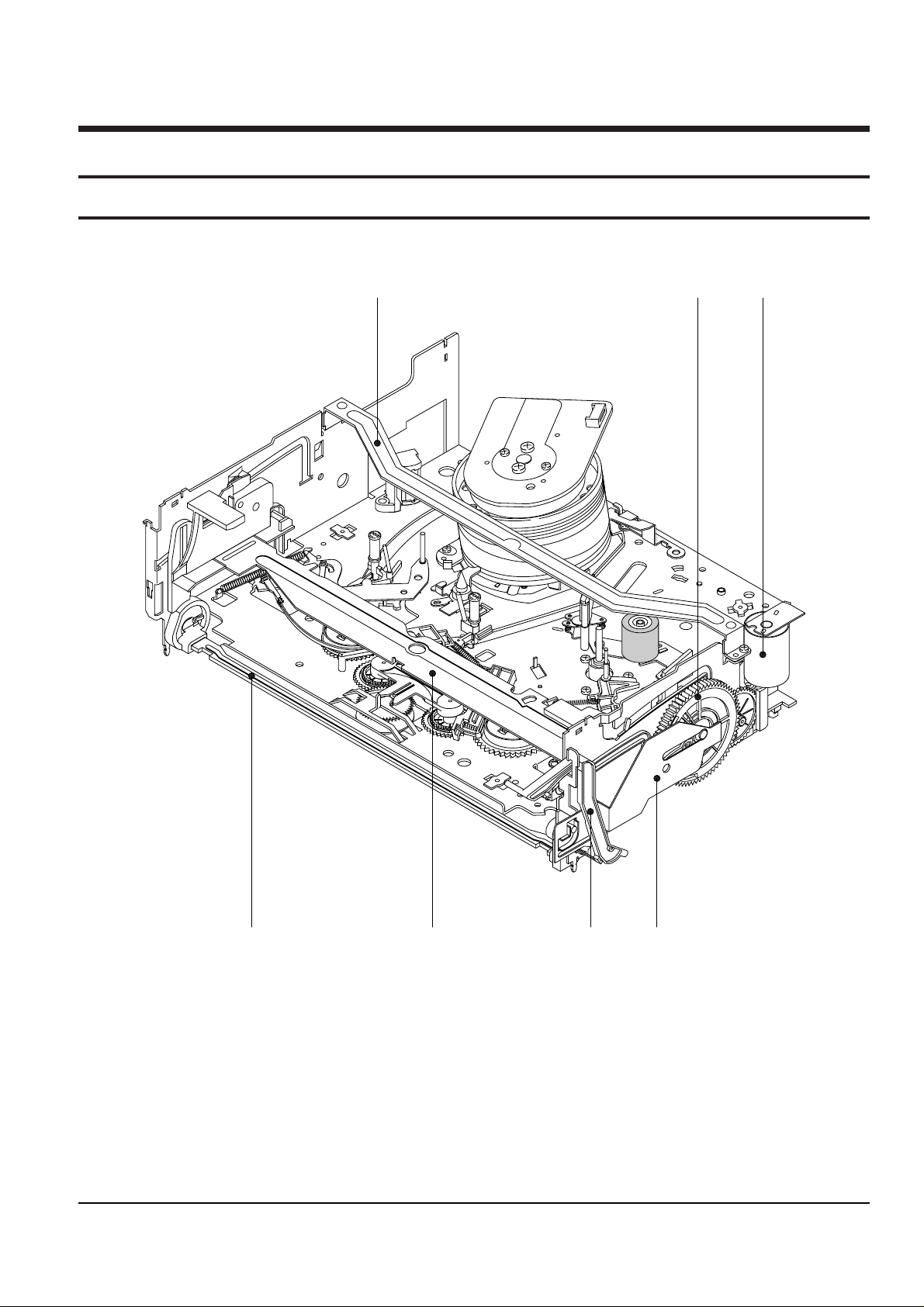
Fig. 1-1 Top parts Location-1
ΠBRACKET FL TOP
´ GEAR FL CAM
ˇ MOTOR LOADING ASS’Y
¨ LEVER FL ARM ASS’Y
ˆ HOLDER FL CASSETTE ASS’Y
Ø LEVER FL DOOR
∏ SLIDER FL DRIVE
1. Disassembly and Reassembly
1-1 Deck Parts Locations
1-1-1 Top View
1-2
Samsung Electronics
Disassembly and Reassembly
Œ
´ ˇ
¨
ˆ
Ø
∏
”
’
˝
Ô
Ò
Ú Æ ı
Ò
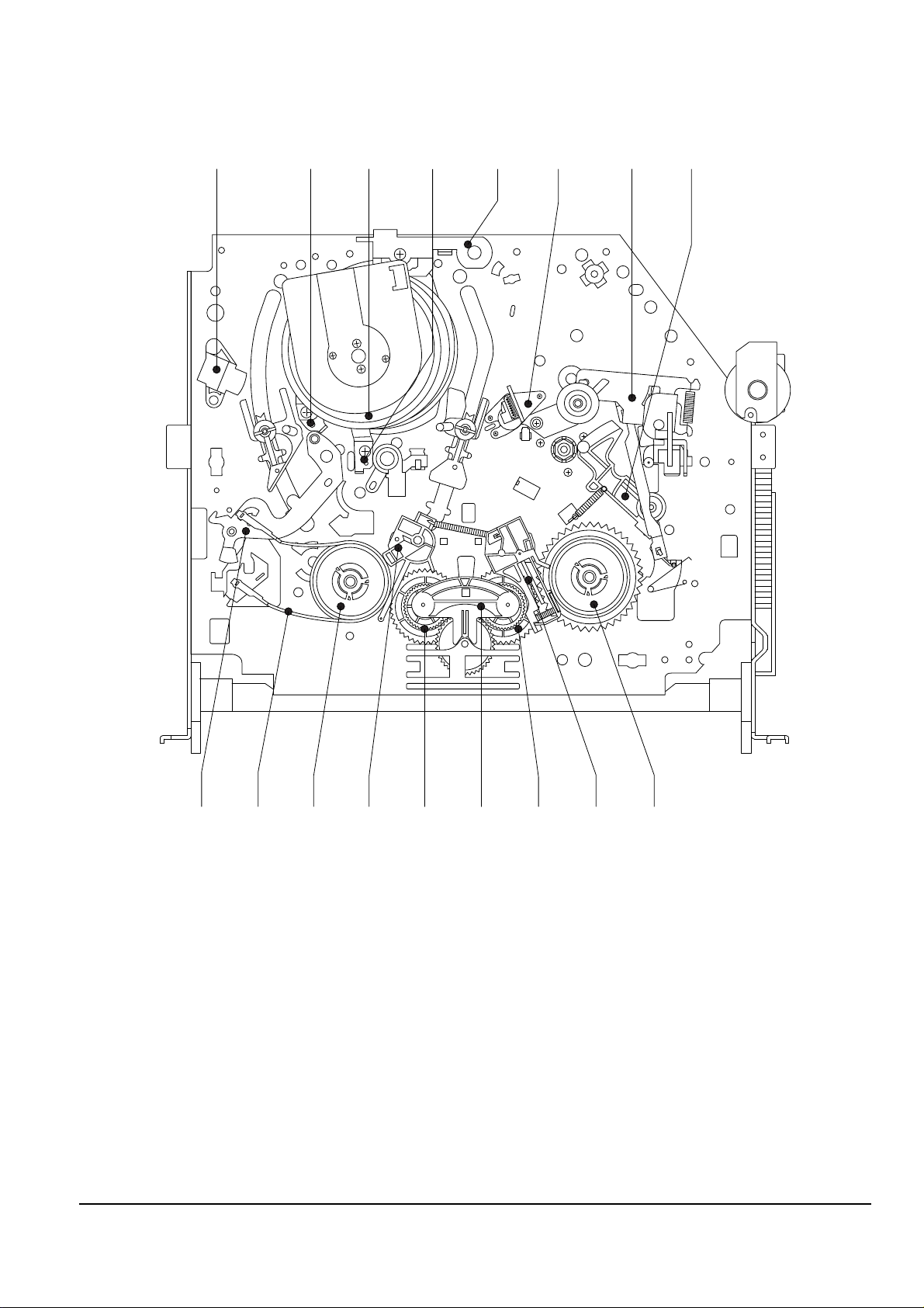
Fig. 1-2 Top Parts Location-2
ΠFE HEAD
´ PLATE CYLINDER C
ˇ CYLINDER ASS’Y
¨ PLATE CYLINDER B
ˆ PLATE CYLINDER A
Ø ACE HEAD ASS’Y
∏ UNIT PINCH ASS’Y
” LEVER #9 GUIDE ASS’Y
’ LEVER TENSION ASS’Y
˝ BAND BRAKE ASS’Y
Ô DISK S REEL
LEVER S BRAKE ASS’Y
Ò GEAR IDLE
Ú LEVER IDLE
Æ LEVER T BRAKE ASS’Y
ı DISK T REEL
Disassembly and Reassembly
Samsung Electronics
1-3
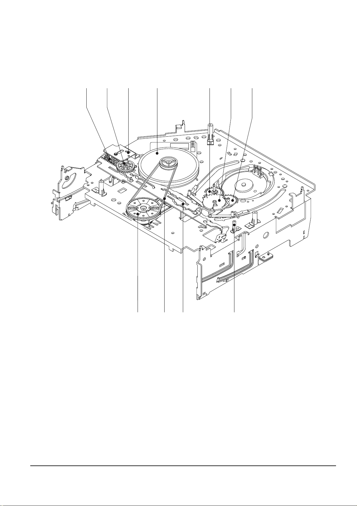
1-1-2 Bottom View
Œ
´
ˇ
¨
ˆ Ø ∏
”
’ ˝
Ô
Fig. 1-3 Bottom Parts Location
ΠGEAR JOINT 1
´ GEAR JOINT 2
ˇ BRAKET GEAR
¨ MOTOR CAPSTAN ASS’Y
ˆ LEVER T LOAD ASS’Y
Ø GEAR LOADING DRIVE
∏ LEVER S LOAD ASS’Y
” HOLDER CLUTCH ASS’Y
’ BELT PULLEY
˝ SLIDER CAM
Ô SLEEVE TENSION
1-4
Samsung Electronics
Disassembly and Reassembly
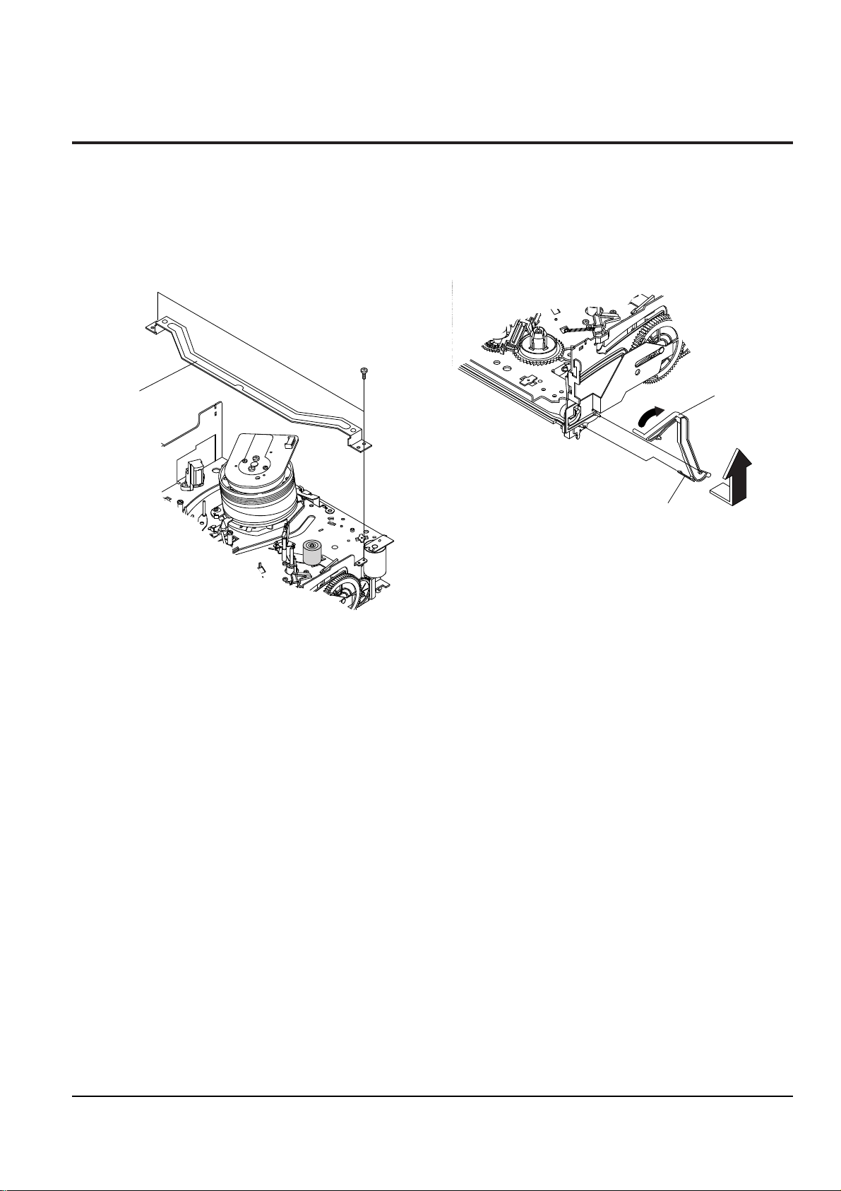
1-2-1 Bracket FL Top Removal
1) Remove 2 screws Œ.
2) Remove the Bracket FL Top ´.
Note : Take care not to change assembly direction.
Π2 SCREWS
´ BRACKET FL TOP
1-2-2 Lever FL Door Removal
1) Rotate the Lever FL Door Πin the direction of
arrow ÒAÓ.
2) Release the Hook ´, remove the Lever FL Door Œ
in the direction of arrow ÒBÓ.
´ HOOK
ΠLEVER FL DOOR
"A"
"B"
1-2 Main Deck
Fig. 1-4 Bracket FL Top Removal
Fig. 1-5 Lever FL Door Removal
Disassembly and Reassembly
Samsung Electronics
1-5
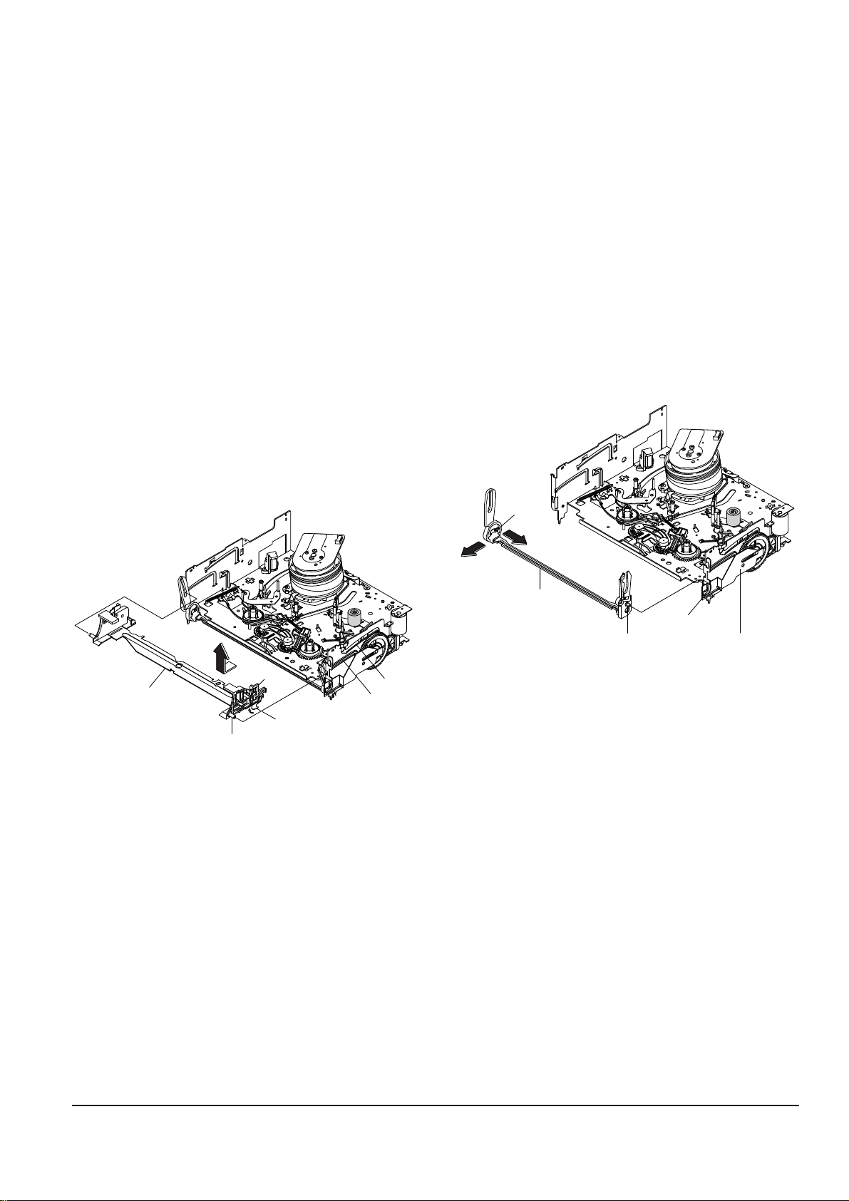
1-2-3 Holder FL Cassette Ass’y Removal
1) Remove the Lever FL Door. (Refer to Fig. 1-5)
2) Pull the Holder FL Cassette AssÕy Œ to the eject
position.
3) Pull the Holder FL Cassette AssÕy Œ as grasping
the Holder FL Cassette AssÕy Œ and Lever FL
Cassette-R ´ in the same time to release hooking
from Main Base until the Boss [A], [B] of Holder
FL Cassette AssÕy Œ is taken out from the Rail [C],
[D].
4) Lift the Holder FL Cassette AssÕy Œ in the direction of arrow ÒBÓ in this time, you have to grasp
the Lever FL Cassette-R ´ continuously until the
Holder FL Cassette AssÕy Œ is taken out completely.
Note : Be sure to insert Lever FL Cassette-R ´ in the
direction of ÒAÓ to prevent separation and breakage
of the Lever FL Cassette-R ´ at disassembling and
reassembling.
ΠHOLDER FL
CASSETTE ASS'Y
´ LEVER FL CASSETTE-R
BOSS [A]
BOSS [B]
RAIL [C]
RAIL [D]
"A"
"B"
1-2-4 Lever FL Arm Ass’y Removal
1) Remove the Lever FL Door. (Refer to Fig. 1-5)
2) Remove the Holder FL Cassette AssÕy.
(Refer to Fig. 1-6)
3) Release the Hook Πin the direction of arrow
ÒAÓ, pull out the Lever FL Arm AssÕy ¨ from the
Boss of Main Base.
4) Remove the Lever FL Arm AssÕy ¨ in the direction of arrow ÒBÓ.
Assembly : When reinstalling, be sure to reassemble
Lever FL Arm AssÕy ¨ after you insert the Boss ´ in
Groove [A] of Slider FL Drive ˇ.
ΠHOOK
´ BOSS
¨ LEVER FL
ARM ASS'Y
ˇ SLIDER FL DRIVE
GROOVE [A]
"A"
"B"
Fig. 1-6 Holder FL Cassette Ass’y Removal
Fig. 1-7 Lever FL Arm Ass’y Removal
1-6
Samsung Electronics
Disassembly and Reassembly
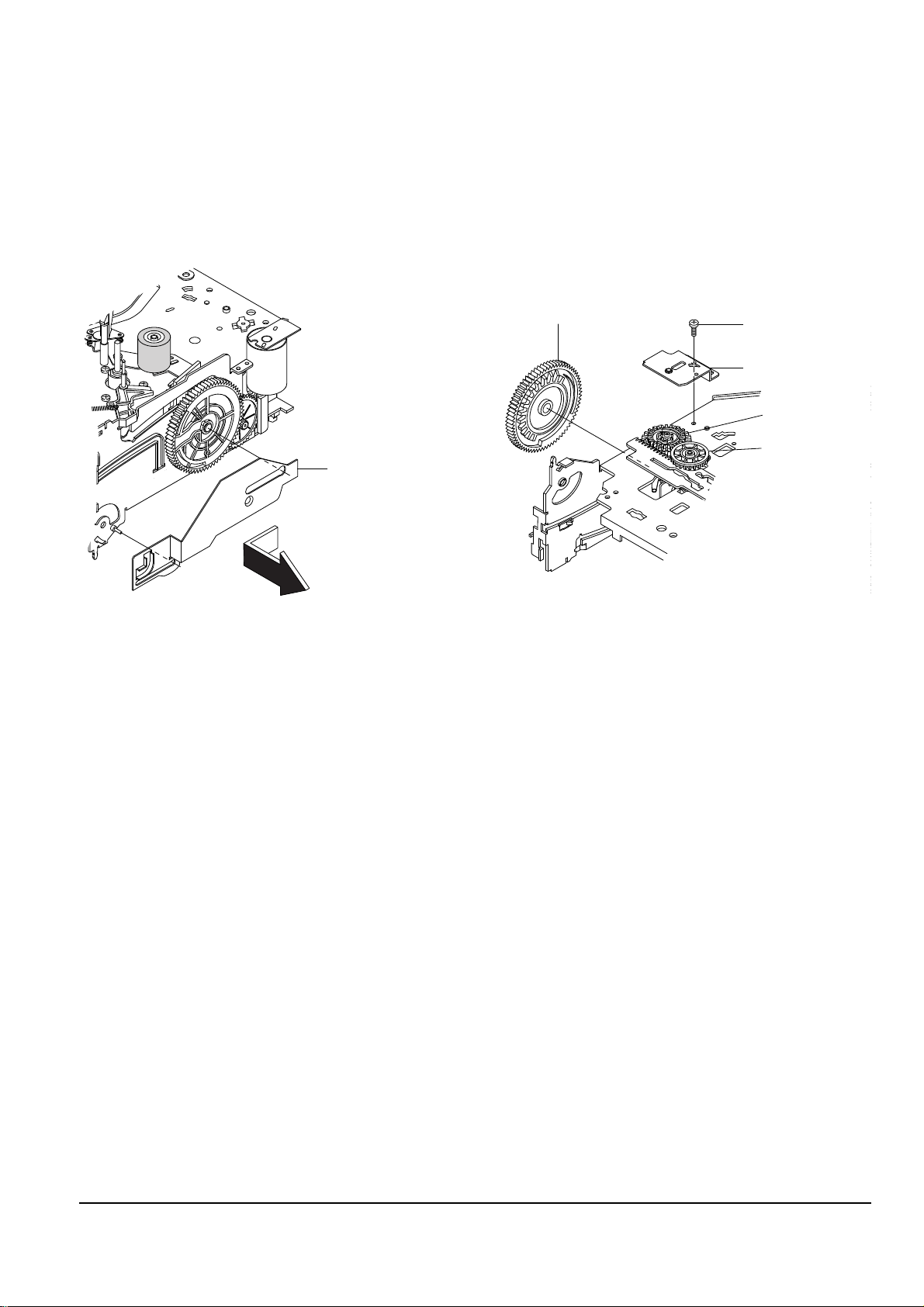
1-2-5 Slider FL Drive Removal
1) Pull the Slider FL Drive Πto the front direction.
2) Remove the Slider FL Drive Πin the direction of
arrow. (Refer to Fig. 1-8)
ΠSLIDER FL DRIVE
1-2-6 Bracket Gear, Gear FL Cam,
Gear Joint 1, 2 Removal
1) Remove screw Œ.
2) Lift the Bracket Gear ´.
3) Remove the Gear FL Cam ˇ.
4) Lift the Gear Joint 2 ¨, Gear Joint 1 ˆ.
ΠSCREW
´ BRACKET GEAR
ˇ GEAR FL CAM
ˆ GEAR JOINT 1
¨ GEAR JOINT 2
Fig. 1-8 Slider FL Drive Removal
Fig. 1-9 Bracket Gear, Gear FL Cam, Gear Joint 1, 2
Removal
Disassembly and Reassembly
Samsung Electronics
1-7
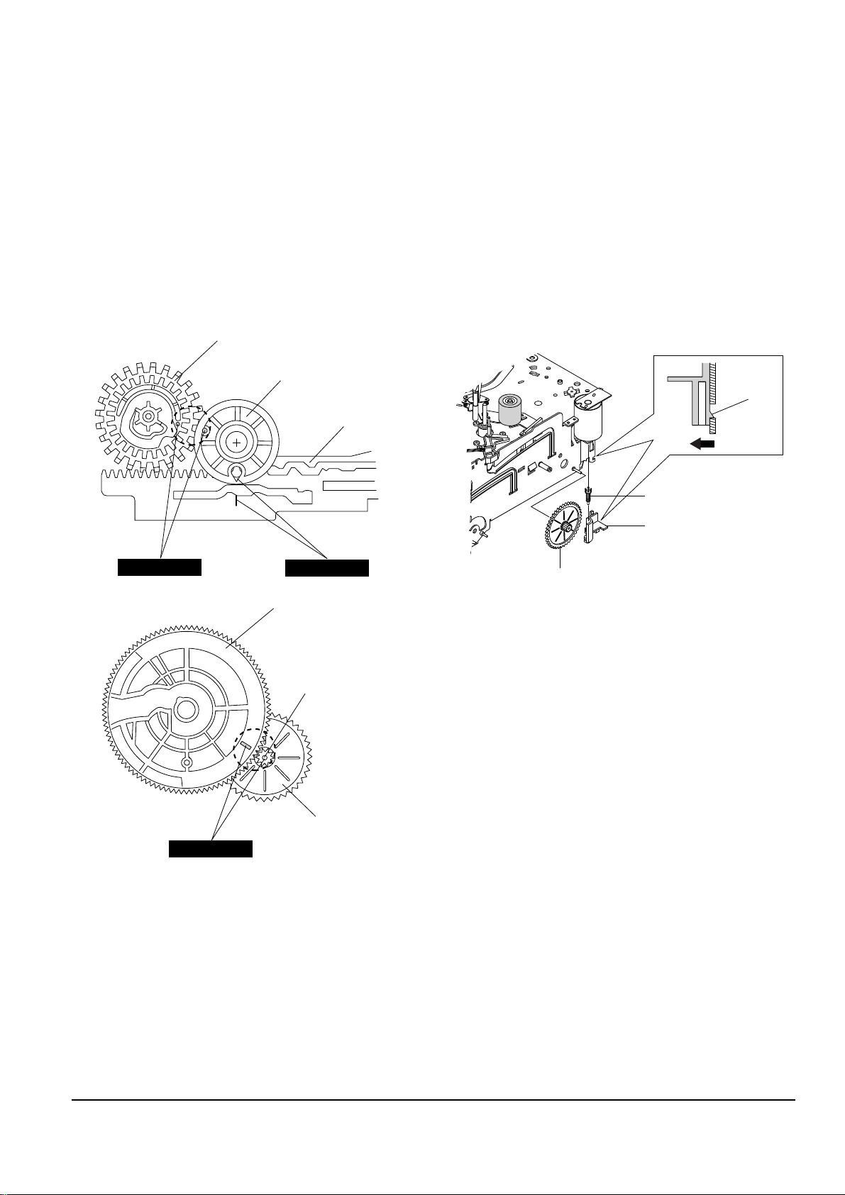
1-2-7 Assembly of Gear FL Cam,
Gear Joint 1, 2
1) Be sure to align dot mark of Gear Joint 1 Πwith
dot mark of Gear Joint 2 ´ as shown Fig. 1-10
(Refer to Timing Point 1), confirm the Timing Point
2 of the Gear Joint 2 ´ and Slider Cam ˇ.
2) Align the Gear FL Cam ¨ with the Gear Worm
Wheel Post as shown detail drawing. (Refer to
Timing Point 3)
ΠGEAR JOINT 1
´ GEAR JOINT 2
ˇ SLIDER CAM
TIMING POINT 1
¨ GEAR FL CAM
GEAR WORM WHEEL
POST
TIMING POINT 2
TIMING POINT 3
1-2-8 Holder Worm, Gear Worm,
Gear Worm Wheel Removal
1) Release the Hook [A] in the direction of arrow and,
remove the Holder Worm Œ.
2) Remove the Gear Worm ´.
3) Remove the Gear Worm Wheel ˇ. (After remov-
ing the Gear FL Cam as shown Fig. 1-9)
Note : Secure the Hook [A] after installing the Holder
Worm Œ.
ΠHOLDER WORM
´ GEAR WORM
HOOK [A]
ˇ GEAR WORM WHEEL
Fig. 1-10 Assembly of Gear FL Cam, Gear Joint 1,2
Fig. 1-11 Holder Worm, Gear Worm,
Gear Worm Wheel Removal
 Loading...