

Samsung DCS, DCS COMPACT, DCS COMPACT II, DCS-816 User Manual

SAMSUNG
DCS
COMBINED
PROGRAMMING
MANUAL
DCS
DCS COMPACT
for
DCS COMPACT II
DCS-816
DCS-408
DCS-408i

Publication Information
Samsung Telecoms reserves the right without prior notice to revise information in
this publication for any reason.
Samsung Telecoms also reserves the right without prior notice to make changes in
design or components of equipment as engineering and manufacturing may warrant.
Disclaimer
Samsung Telecoms is not responsible for errors or problems arising from customers
not installing, programming or operating their Samsung systems as described in this
manual.
Copyright 2001
Samsung Telecoms (UK) Limited
All rights reserved. No part of this manual may be reproduced in any form or by any
means – graphic, electronic or mechanical, including recording, taping, photocopy or
information retrieval system – without express written permission of the publisher of
this material.
Part No.:12623 Version 2.0

EU Declaration of Conformity
For other directives relevant to DCS Compact II, DCS-816, DCS-408 and DCS-408i systems,
refer to the Samsung website at:
www.samsung-telecoms.co.uk

DCS CONTENTS
COMBINED PROGRAMMING MANUAL NOVEMBER 2001
Contents
Part
1 Introduction to Programming .....................................1–1
1.1 Using this Manual...........................................................................1–1
1.2 Programming Overview ..................................................................1–2
1.3 Programming Levels......................................................................1–2
1.3.1 System Level ............................................................................ 1–2
1.3.2 Customer Level ......................................................................... 1–2
1.3.3 Station Level............................................................................. 1–3
1.4 Keys Used for Programming ..........................................................1–3
1.4.1 Soft Keys .................................................................................. 1–3
1.4.2 Other Keys ............................................................................... 1–3
1.5 Programming Procedures..............................................................1–4
1.5.1 Precautions When Programming ............................................... 1–4
1.5.2 Opening System or Customer Level Programming ..................... 1–4
1.5.3 Opening Station Level Programming.......................................... 1–5
1.5.4 Programmi ng DCS-408 and 408i Systems..................................1–5
2 Program (MMC) List and Default Data ......................2–1
2.1 Program (MMC) List.......................................................................2–1
2.2 Default Data....................................................................................2–3
2.3 System Configuration: Quick Reference...................................... 2–9
3 Special Applications ....................................................3–1
Voice Mail / Auto Attendant Integration...................................................3–2
Individual Station Page............................................................................3–4
CLIP (Calling Line Identification Presentation)........................................3–5
Toll Restriction (Call Barring) Overview ...................................................3–6
S0 Overview.............................................................................................3–8
4 MMCs (in numerical order) ........................................4–1

DCS INTRODUCTION
COMBINED PROGRAMMING MANUAL NOVEMBER 2001
Part 1. Introduction to Programming
This manual describes the MMC pro gramming required for the following types of Samsung DCS keyphone system:
• DCS
• DCS Compact (Compact I)
• DCS Compact II
• DCS-816
• DCS-408
• DCS-408i.
In this manual, these systems are referred to as “DCS,” “Compact I (CI),” “Compact II
(CII)," "816," "408" and “408i” respectively. Programming requirements for these system
types are generally the same, but occasionally there are differences. Users of 408 and
408i systems should also read Programming DCS-408 and 408i Systems in section 1.5.4
of this manual. Unless otherwise stated, references to “DCS” include Compact I sy stems.
The different system types are discussed fully in the separate Samsung General De-
scription manuals for each system, where these have been published.
Software Version Numbers
The software version numbers of the systems for which this programming manual is
relevant are: DCS and Compact II=V6.10 or later; 816=V1.09 or later; 408 and
408i=1.04 or later.
1.1 Using This Manual
• It is recommended that you read the whole of Part 1 of this manual which provides a
useful overview to MMC programming procedures.
• For a comprehensive list of available MMCs, see Part 2.
• For quick reference, Part 2 also provides a table listing the default settings for each
MMC and indicating which systems can use each MMC . A “Y” (“Yes”) in the appropriate column indicates that it can be used for that system.
• To quickly check allowed configuration settings for each type of system—number of
trunk group members, card port numbers, and so on—see section 2.3 System Con-
figuration: Quick Reference in Part 2.
• To begin programming, refer to the appropriate MMC(s) in Part 4. Check the se-
lected MMC header bar to make sure the program is available on your system, if
you haven’t already done so.
• Refer to Part 3, Special Applications, for further information on voice mail / auto at-
tendant integration, individual station paging, CLIP (Calling Line Identification Presentation), toll restriction (call barring) and S
0 programming.
1-1

DCS INTRODUCTION
COMBINED PROGRAMMING MANUAL NOVEMBER 2001
1.2 Programming Overview
When the keyphone system arrives from the factory it contains default data. This needs
to be customised, using the MMC programs, to suit the customer’s requirements.
MMC stands for Man Machine Code and each MMC is assigned a three-digit code (100,
101, and so on). These MMCs are used to view, create or change customer data on a
display keyphone (called KMMC programming). For example, MMC 601 is used to cr eate a station group; sy stem speed dial numbers are entered in MMC 705; key functions
are assigned to individual keyphones (or “keysets”) using MMC 722; and system dialling codes (such as extension numbers and feature codes) can be changed in MMC
724.
1.3 Programming Levels
There are three levels of programming: System level, Customer level and Station level.
System and Customer levels allow system-wide programming and are under passcode
protection to restrict access. System programming is done by the system installer (or
system technician), usually on a one-off basis, but also to manage any changes in the
customer’s requirements. Customer programming is done by the system administrator,
on a day to day basis, to manage station users’ requirements. Station level programming does not require a passcode, allowing station users to make simple changes to
their keyset features.
To prevent conflicting data from being entered, only one person at a time can enter System or Customer programming. If you attempt to enter programming mode while another keyset is being used for programming, your display shows [xxx PGM MODE]
where “xxx” is the key set extension number of the station in programming mode. While
programming is in progress, normal system operation is not affected.
1.3.1 System Level
This level is entered via MMC 800 and requires the installer’s (technician’s) passcode.
This is the highest level and allows access to all system programs, station programs
and mainte nance programs. The installer (sometimes called the installing technician)
also decides which programs are accessible to the customer (the system administrator)
at Customer level.
• All MMCs are accessible at this level.
1.3.2 Customer Level
This level is entered via MMC 200 and requires the customer’s passcode. It allows access to station programs and system programs permitted by the system installer in
MMC 802. When the system administrator uses the customer passcode to access station programs, data for all stations can be viewed or changed. Changes can be made
either system-wide or to selected keysets. (The system administrator should also refer
to the System Administration manual for their keyphone system if this is available.)
• Accessible MMCs at this level are designated by the installer.
1-2
DCS INTRODUCTION
COMBINED PROGRAMMING MANUAL NOVEMBER 2001
1.3.3 Station Level
The system administrator or keyset user can access certain programs at a station without using a passcode. At this level, only data for the selected station can be changed.
You should refer to the instructions provided in the Samsung DCS Keyset User Guide.
• Accessible MMCs at this level are nos. 100–121.
1.4 Keys Used for Programming
Programming may be done from any 6-button (6B), 12-button (12B) or 24-button (24B)
keyset with a liquid crystal display (LCD). (Refer to the Samsung DCS Keyset User Guide
for a full description of keyset operation.)
1.4.1 Soft Keys
The three keys directly below
the LCD are called soft keys.
The left-hand soft key is designated as the LEFT soft key. This
key is used to save any
changed data while programming, or to move the cu rsor to
the left on the LCD.
The right-hand soft key is designated as the RIGHT soft key.
This key is used to save any
changed data while programming, or to move the cursor to
the right on the LCD.
DCS Euro Display Keysets
1.4.2 Other Keys
The following keys perform special functions:
VOLUME UP (+) / DOWN ( –) Scroll up/down through available options*
KEYPAD Enter data using keys 0 –9 and [, and dial options*
HOLD Clear previous entry
ANS/RLS Select “ALL” option (e.g. to make data apply to all,
rather than selected, stations)
SPEAKER Store data and advance to next MMC
TRSF Enter programming mode or
Store data and exit programming mode
* Note: Many MMCs allow you to dial codes using the keypad to select options quickly. Alternatively, you can press the VOLUME Up and Down keys (+ and – ) to scroll through and select options. Use whic hever method you prefer.
1-3
DCS INTRODUCTION
try
y-
select the country and press the RIGHT soft key.
Use the VOLUME Up/Down keys to select YES and press the RIGHT soft key. When
scribed next. The
COMBINED PROGRAMMING MANUAL NOVEMBER 2001
The 6, 12 or 24 extra programmable keys can be set up to perform specific functions
when pressed during normal operation. During programming, some of these keys also
perform other specific functions. This is described in the individual MMC program procedure where applicable.
1.5 Programming Procedures
1.5.1 Precautions When Programming
• The keyset must be on-hook (handset down) to allow programming.
• Programming is available on any digital keyset with an LCD.
• Programming is available only on digital telephones (not analogue ones).
• If ‘INVALID DATA’ appears in the LCD while programming, you should re-enter the
correct data.
• When you have successfully completed an entry, the LCD automatically changes for
the next step.
• Programming halts if you have not pressed a key for a certain period of time (30 se conds by default, but this can be changed).
• Programming halts if you pick up the handset while programming.
• If you pick up the handset while programming, or the telephone plug is pulled out,
any new data shown in the LCD are saved.
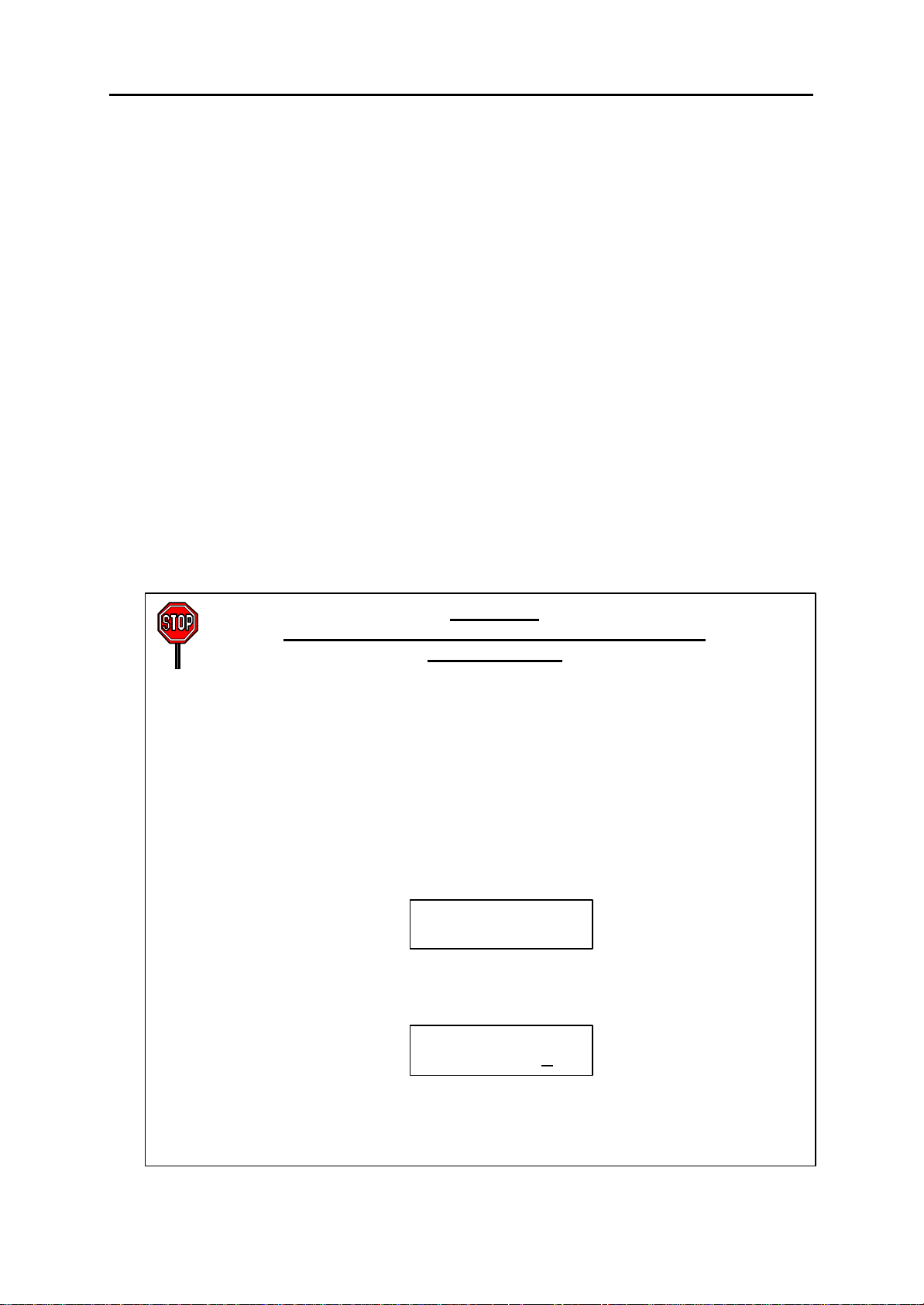
IMPORTANT
When installing and programming a ‘default’ system
for the first time:
The system requires that you select the correct software version for your coun
(e.g. by selecting “UK”) before you can do any other programming via either a ke
phone (KMMC programming) or a PC (PCMMC programming).
To select the country:
1. Press the TRSF key.
2. Enter 800 followed by the default passcode (4321)
The system sounds a warning and displays on the keyset:
Use the VOLUME Up/Down keys to
The keyset displays:
ENABLE TECH. PROG
SELECT COUNTRY
DEFAULTING SYSTM
ARE YOU SURE?NO
defaulted to the correct version, you can open programming as de
country version selected can be changed in MMC 812, Select Country.
1-4

DCS INTRODUCTION
COMBINED PROGRAMMING MANUAL NOVEMBER 2001
1.5.2 Opening System or Customer Programming
To open programming:
1. Press the TRSF key.
2. Enter the MMC program number 200 (for Customer level programming) or 800 (for
System level programming).
3. Enter the relevant passcode.
4. Press key 1 (or use the VOLUME Up or Down key) to select ‘ENABLE’.
5. Press the SPEAKER key to have the program selection mode appear (or press the
TRSF key to halt programming).
6. Enter the MMC number, or select the program number with the Up or Down key and
press the SPEAKER key.
When opening system programming, you are advised to check MMC 812 (Select Country) to ensure that the correct country has been selected before you do any other programming.
Carefully follow the instructions given with each MMC to program your system correctly.
1.5.3 Opening Station Level Programming
To open programming:
1. Press the TRSF key.
2. Enter the MMC program number.
Carefully follow the instructions given with each MMC to program your system correctly.
1.5.4 Programming DCS-408 and 408i Systems
Although physically similar in appearance, the “408” and “408i” are different systems and
may have different programming requirements and features. For example, the 408i supports ISDN whereas the 408 does not. Thus, an MMC relevant to one system may not be
relevant to the other. Similarly, where an MMC relates to both systems, some features
available on the 408i system may not be available on the 408 system, and vice versa.
This will be indicated in the MMC description, where appropriate.
These systems also differ significantly from all other keyphone systems, both in size and
physical appearance. In comparison with other systems, when programming your 408 or
408i:
• Extension, group and trunk numbers are two digits by default (e.g. extension 21,
trunk 71, etc). All other systems use 3-digit numbers by default (e.g. extension 201,
trunk 701, etc).* Examples of programming shown in this manual use 3-digit numbers for convenience only.
(*Unless changed by the system installer in MMC 724.)
• You can set up to four ‘Normal’ station groups. Group types AA, VM/AA and UCD
are not permitted.
• Only two trunk groups, 8 and 9, are available. (All other systems support groups 9
and 80–82.)
1-5

DCS MMC LIST
COMBINED PROGRAMMING MANUAL NOVEMBER 2001
Part 2. Program MMC List & Default Data
2.1 Program (MMC) List
100: STATION LOCK 317: ASSIGN STATION/STATION USE
101: CHANGE USER PASSCODE 318: DISTINCTIVE RING
102: CALL FORWARD 319: BRANCH GROUP
103: SET ANSWER MODE 400: CUSTOMER ON/OFF PER TRUNK
104: STATION NAME 401: CO/PBX LINE
105: STATION SPEED DIAL 402: TRUNK DIAL TYPE
106: STATION SPEED DIAL NAME 403: TRUNK TOLL CLASS
107: KEY EXTENDER 404: TRUNK NAME
108: STATION STATUS 405: TRUNK NUMBER
109: DATE DISPLAY 406: TRUNK RING ASSIGNMEN T
110: STATION ON/OFF 407: FORCED TRUNK RELEASE
111: KEYSET RING TONE 408: ASSIGN TRUNK MUSIC ON HOLD SOURCE
112: ALARM REMINDER 409: TRUNK STATUS READ
113: VIEW MEMO NUMBER 410: ASSIGN DISA TRUNK
114: STATION VOLUME 411: ASSIGN E1 SIGNAL TYPE
115: SET PROGRAMMED MESSAGE 412: ASSIGN TRUNK SIGNAL
116: ALARM AND MESSAGE 414: MPD/PRS SIGNAL
119: SET CLIP DISPLAY 415: REPORT TRUNK ABANDON DATA
121: KEYSET LANGUAGE 416: ASSIGN AC15 TRANSLATION
200: OPEN CUSTOMER PROGRAMMING 417: PRI CRC4 OPTION
201: CHANGE CUSTOMER PASSCODE 418: CARD RESTART
202: CHANGE FEATURE PASSCODES 419: BRI OPTION
203: ASSIGN UA DEVICE 420: PRI OPTION
204: COMMON BELL CONTROL 421: MSN DIGIT
205: ASSIGN LOUD BELL 422: ASSIGN TRUNK COS
206: BARGE-IN TYPE 423: S/T MODE
207: ASSIGN VM/AA PORT 424: S0 MAPPING
208: ASSIGN RING TYPE 426: TRUNK GAIN CONTROL
209: ASSIGN ADD-ON MODULE 427: R2MFC SIGNAL
210: CUSTOMER ON/OFF 428: ASSIGN TRUNK/TRUNK USE
211: DOOR RING ASSIGNMENT 500: SYSTEM-WIDE COUNTERS
212: ALARM RINGING STATION 501: SYSTEM-WIDE TIMERS
213: ALARM MESSAGE 502: STATION-WIDE TIMERS
214: DISA ALARM RINGING STATION 503: TRUNK-WIDE TIMERS
215: VOICE DIALLER OPTION S 504: PULSE MAKE/BREAK RATIO
216: VOICE DIALLER ASSIGNMENTS 505: ASSIGN DATE AND TIME
217: CCC OPTION 506: TONE CADENCE
219: COMMON RELAY SERVICE TYPE 507: ASSIGN AUTO NIGHT TIME
220: ISDN SERVICE TYPE 508: CALL COST
300: CUSTOMER ON/OFF PER STATION 509: C.O. TONE CADENCE
301: ASSIGN STATION COS 510: SLI RING CADENCE
302: PICKUP GROUPS 511: MW LAMP CAD
303: ASSIGN BOSS/SECRETARY 512: ASSIGN HOLIDAY
304: ASSIGN STA TION/TRUNK USE 600: ASSIGN OPERATOR GROUP
305: ASSIGN FORCED CODE 601: ASSIGN STATION GROUP
306: HOT LINE 602: STATION GROUP NAME
308: ASSIGN BACKGROUND MUSIC SOURCE 603: ASSIGN TRUNK GROUP
309: ASSIGN STATION MUSIC ON HOLD 604: ASSIGN STATION TO PAGE ZONE
310: LCR CLASS OF SERVICE 605: ASSIGN EXTERNAL PAGE ZONE
311: ASSIGN SIM PARAMETER 606: ASSIGN SPEED BLOCK
312: ALLOW CLIP 607: UCD OPTIONS
313: ASSIGN PIN CODE 608: ASSIGN CLIP REVIEW BLOCK
314: CONFIRM OUTGOING CAL L 700: COPY COS CONTENTS
315: SET RELOCATION 701: ASSIGN COS CONTENTS
316: COPY STATION USABLE 702: TOLL DENY TABLE
2-1

DCS MMC LIST
COMBINED PROGRAMMING MANUAL NOVEMBER 2001
703: TOLL ALLOWANCE TABLE 736: ASSIGN AA MOH
704: ASSIGN WILD CHARACTER 737: DECT SYSTEM CODE
705: ASSIGN SYSTEM SPEED DIAL 738: DECT CLEAR REGISTRATION
706: SYSTEM SPEED DIAL BY NAME 739: BSI DOWNLOAD
707: AUTHORISATION CODE 740: STATION PAIR
708: ACCOUNT CODE 741: BSI CARD RESTART
709: PBX ACCESS CODE 742: BSI STATUS
710: LCR DIGIT TABLE 743: DECT BASE STATION (DBS) STATUS
711: LCR TIME TABLE 744: DECT REGISTRATION ON/OFF
712: LCR ROUTE TABLE 745: BSI CARRIER
713: LCR MODIFY DIGIT TABLE 750: VM CARD RESTART
714: DDI NUMBER & NAME TRANSLATION 751: ASSIGN MAILBOX
715: PROGRAMMED STATION MESSAGE 752: AUTO RECORD
716: UK LCR OPTION 753: WARNING DESTINATION
717: PIN CODE 754: VM HALT
718: MY AREA CODE 755: VM ALARM
720: COPY KEY PROGRAMMING 756: ASSIGN VM MOH
721: SAVE STATION KEY PROGRAMMING 757: VM IN/OUT
722: STATION KEY PROGRAMMING 800: ENABLE TECHNICIAN PROGRAM
723: SYSTEM KEY PROGRAMMING 801: CHANGE TECHNICIAN PA SSCODE
724: DIAL NUMBERING PLAN 802: CUSTOMER ACCESS MMC NUMBER
725: SMDR OPTIONS 803: ASSIGN TENANT GROUP
726: VM/AA OPTIONS 804: SYSTEM I/O PARAMETER
727: SYSTEM VERSION DISPL AY 805: TX LEVEL & GAIN
728: CLIP TRANSLATION TA BLE 806: CARD PRE-INSTALL
730: AA RECORD GAIN 807: VOLUME CONTROL
731: AA RAM CLEAR 808: T1 TRUNK CODING
732: AA TRANSLATION TABLE 809: SYSTEM MMC LANGUAGE
733: AA PLAN TABLE 810: HALT PROCESSING
734: AA MESSAGE MATCH 811: RESET SYSTEM
735: AA USE T ABLE 812: SELECT COUNTRY
2-2

DCS DEFAULT DATA
COMBINED PROGRAMMING MANUAL NOVEMBER 2001
2.2 Default Data
Station Programs
DCS CI CII 816 408 408i
100: STATION LOCK Y Y Y Y Y Y ALL STATIONS UNLOCKED
101: CHANGE USER PASSCODE Y Y Y Y Y Y ALL STATION PASCODES=1234
102: CALL FORWARD Y Y Y Y Y Y ALL STATION=0 (FWD CANCEL)
103: SET ANSWER MODE Y Y Y Y Y Y
104: STATION NAME Y Y Y Y Y Y NONE
105: STATION SPEED DIAL Y Y Y Y Y Y NONE
106: STATION SPEED DIAL NAME Y Y Y Y Y Y NONE
107: KEY EXTENDER Y Y Y Y Y Y NONE
108: STATION STATUS Y Y Y Y Y Y SEE MMC 108
109: DATE DISPLAY Y Y Y Y Y Y COUNTRY: WESTERN
110: STATION ON/OFF Y Y Y Y Y Y AUTO HOLD: OFF
111: KEYSET RING TONE Y Y Y Y Y Y SELECTION=5
112: ALARM REMINDER Y Y Y Y Y Y ALARMS SET TO NOTSET
113: VIEW MEMO NUMBER Y Y Y Y Y Y NO MEMOS ENTERED
114: STATION VOLUME Y Y Y Y Y Y RING VOL: 4
115: SET PROGRAMMED MESSAGE Y Y Y Y Y Y NO MESSAGES SELECTED
116: ALARM AND MESSAGE Y Y Y Y Y Y ALARMS SET TO NOTSET
119: SET DISPLAY Y Y Y Y N Y NAME FIRST
121: KEYSET LANGUAGE Y N Y Y Y Y ENGLISH
ALL KEYSETS ‘RING’
RING FREQUENCY DEFAULT=5
CLOCK: 24-HOUR
DISPLAY: LOWERCASE
AUTO TIMER: ON
HEADSET MODE: OFF
HOT KEYPAD: ON
KEY TONE: ON
PAGE REJOIN: ON
RING PREFERENCE: ON
CALL COST: OFF
AME BGM: OFF
AME PSWD: OFF
OFF HOOK RING VOL: 4
HANDSET VOL: 4
SPEAKER VOL: 13
BGM VOL: 13
2-3

DCS DEFAULT DATA
COMBINED PROGRAMMING MANUAL NOVEMBER 2001
System Programs
200: OPEN CUSTOMER PROGRAMMING Y Y Y Y Y Y CLOSED (DISABLED)
201: CHANGE CUSTOMER PASSCODE Y Y Y Y Y Y PASSCODE =1234
202: CHANGE FEATURE PASSCODES Y N Y Y Y Y DAY/NIGHT=0000
203: ASSIGN UA DEVICE Y Y Y Y Y Y NONE
204: COMMON BELL CONTROL Y Y Y Y Y Y CONTINUOUS
205: ASSIGN LOUD BELL Y N Y Y Y Y UNASSIGNED
206: BARGE-IN TYPE Y Y Y Y Y Y NO BARGE IN
207: ASSIGN VM/AA PORT Y Y Y Y Y Y NORMAL PORT
208: ASSIGN RING TYPE Y Y Y Y Y Y ICM RING
209: ASSIGN ADD-ON MODULE Y Y Y Y N N NONE FOR MASTER
210: CUSTOMER ON/OFF Y Y Y Y Y Y SEE MMC 210
211: DOOR RING ASSIGNMENT Y Y Y Y Y Y STATION GROUP 500 (or 50)
212: ALARM RINGING STATION Y N Y N N N ALL SENSORS RING 500
213: ALARM MESSAGE Y N Y N N N NONE
214: DISA ALARM RINGING STATION Y Y Y Y Y Y DAY/NIGHT=500 (or 50)
215: VOICE DIALLER OPTIONS Y Y Y N N N 2CH-7USER-20BIN
216: VOICE DIALLER ASSIGNMENTS Y Y Y N N N NONE
217: CCC OPTION N Y N N N N NONE
219: COMMON RELAY SERVICE TYPE N N Y Y Y Y SEE MMC 219
220: ISDN SERVICE TYPE Y Y Y Y N Y VOICE
300: CUSTOMER ON/OFF PER STATION Y Y Y Y Y Y STN CALL PRT : OFF
301: ASSIGN STATION COS Y Y Y Y Y Y DAY CLASS = 1
302: PICKUP GROUPS Y Y Y Y Y Y ALL STATIONS GROUP 1
303: ASSIGN BOSS/SECRETARY Y Y Y Y Y Y NONE
304: ASSIGN STATION/TRUNK USE Y Y Y Y Y Y DIAL = YES
305: ASSIGN FORCED CODE Y Y Y Y Y Y NONE
306: HOT LINE Y Y Y Y Y Y NONE
308: ASSIGN BACKGROUND MUSIC
SOURCE
309: ASSIGN STATION MUSIC ON HOLD Y Y Y Y Y Y NONE
310: LCR CLASS OF SERVICE Y Y Y Y Y Y LEAST COST ROUTING
DCS CI CII 816 408 408i
Y Y Y Y Y Y NONE
DISA ALARM=5678
ALARM CLR=8765
AA RECORD=4321
DECT (BSI) REGISTER =4321
DAY/NIGHT
FWD DLY USE : OFF
OTHER FEATURES SET TO
ON
NIGHT CLASS = 1
ANS = YES
COS 1
2-4

DCS DEFAULT DATA
COMBINED PROGRAMMING MANUAL NOVEMBER 2001
DCS CI CII 816 408 408i
311: ASSIGN SIM PARAMETER Y N N N N N SIM TYPE = DTE
312: ALLOW CLIP Y Y Y Y N Y RCV=YES, SEND=YES,
313: ASSIGN PIN CODE N Y N N N N ALL STATIONS ARE CODE
314: CONFIRM OUTGOING CALL Y N Y Y Y Y NONE
315: SET RELOCATION Y N Y Y Y Y NONE
316: COPY STATION USABLE Y N Y Y N N NONE
317: ASSIGN STATION/STATION USE Y N Y Y N N DIAL=YES
318: DISTINCTIVE RING Y N Y Y Y Y T=F-STN, C=F-STN
319: BRANCH GROUP – – – – – – NOT USED IN UK
400: CUSTOMER ON/OFF PER TRUNK Y Y Y Y Y Y 1A2 EMULATE: OFF
401: C.O./PBX LINE Y Y Y Y Y Y ALL TRUNKS C.O. LINE
402: TRUNK DIAL TYPE Y Y Y Y Y N ALL TRUNKS DTMF
403: TRUNK TOLL CLASS Y Y Y Y Y Y ALL TRUNKS F-STN
404: TRUNK NAME Y Y Y Y Y Y NO NAMES ENTERED
405: TRUNK NUMBER Y Y Y Y Y Y NO NUMBERS ENTERED
406: TRUNK RING ASSIGNMENT Y Y Y Y Y Y ALL TRUNKS DAY/NIGHT:
407: FORCED TRUNK RELEASE Y Y Y Y Y Y NONE
408: ASSIGN TRUNK MUSIC ON HOLD
SOURCE
409: TRUNK STATUS READ Y Y Y Y Y Y SEE MMC 409
410: ASSIGN DISA TRUNK Y Y Y Y Y Y ALL TRUNKS NORMAL
411: ASSIGN E1 SIGNAL TYPE – – – – – – NOT USED IN UK
412: ASSIGN TRUNK SIGNAL Y Y Y N N N IMMEDIATE
414: MPD/PRS SIGNAL Y Y Y Y Y N NONE
415: REPORT TRUNK ABANDON DATA Y Y Y Y N Y REPORT=YES
416: ASSIGN AC15 TRANSLATION Y Y Y N N N UNUSE DID TRANS
417: PRI CRC4 OPTION Y N Y N N N CRC4 ON
418: CARD RESTART Y Y Y Y N Y NONE
Y Y Y Y Y Y TONE
CALL MODE = MANUAL
ANS MODE = MANUAL
AUTO BAUD = ON
DTR CHECK = ON
ECHO = ON
PROTOCOL = V110
SPEED = 9600
CHAR LENGTH = 8 BITS
PARITY = NONE
STOP BIT = 1
INFO=CO Tel
#1
TRUNK INC DND: OFF
TRUNK FORWARD: ON
LCR ALLOW:OFF
DAY/NIGHT
500 (or 50)
2-5

DCS DEFAULT DATA
COMBINED PROGRAMMING MANUAL NOVEMBER 2001
DCS CI CII 816 408 408i
419: BRI OPTION Y Y Y Y N Y CHANNEL ANY: YES
420: PRI OPTION Y N Y N N N CHANNEL ANY: YES
421: MSN DIGIT Y Y Y Y N Y NONE
422: ASSIGN TRUNK COS Y Y Y Y Y Y DAY CLASS: 1
423: S/T MODE Y Y Y Y N Y TRUNK
424: S0 MAPPING Y Y Y Y N Y NONE
426: TRUNK GAIN CONTROL Y N Y Y Y Y RX=+0.0 dB, TX=+0.0 dB
427: R2MFC SIGNAL N N N N N N NOT USED IN UK
428: ASSIGN TRUNK/TRUNK USE Y N Y Y N N DIAL=YES
500: SYSTEM-WIDE COUNTERS Y Y Y Y Y Y SEE MMC 500
501: SYSTEM-WIDE TIMERS Y Y Y Y Y Y SEE TABLE OF TIMERS
502: STATION-WIDE TIMERS Y Y Y Y Y Y NO ANS FWD: 015 SEC
503: TRUNK-WIDE TIMERS Y Y Y Y Y Y ANS.BAK TM: 600 MS
504: PULSE MAKE/BREAK RAT IO Y Y Y Y Y N MAKE/BREAK = 33
505: ASSIGN DATE AND TIME Y Y Y Y Y Y FOLLOWS S/W VERSION
506: TONE CADENCE Y Y Y Y Y Y SEE MMC 506
507: ASSIGN AUTO NIGHT TIME Y Y Y Y Y Y NONE
508: CALL COST Y Y Y Y Y Y UNIT COST PER MP: 200
509: C.O. TONE CADENCE N Y N N N N SEE MMC 509
510: SLI RING CADENCE Y Y Y Y Y Y SEE MMC 510
511: MW LAMP CAD Y N Y N N N ON: 1000MS, OFF: 1000MS
512: ASSIGN HOLIDAY Y N Y Y Y Y NONE
600: ASSIGN OPERATOR GROUP Y Y Y Y Y Y DAY/NIGHT: 500 (or 50)
BRI MODE: P-P DDI
DLSEND: OVERLAP
BRI CODING: A-LAW
POWERFEED: NO
PRI MODE: DDI
DLSEND: OVERLAP
NIGHT CLASS: 1
(ALL TRUNKS)
AND VALUES IN MMC 501
DTMF DURATION: 100 MS
FIRST DGT DELAY: 600 MS
CLEARING: 002 SEC
CO SUPV TM: 400 MS
DTMF DURATION: 100 MS
FIRST DGT DELAY: 600 MS
FLASH TIME: 070 MS
NO RING TM: 004 SEC
PAUSE TIME: 003 SEC
PRS DET TM: 000 MS
RNG DET.TM: 300 MS
WINK: 200 MS
MF/DP INT TM: 0800 MS
MFR DLY TM: 000 SEC
PULSES PER SECOND = 10
RELEASE DATE
PENCE
CALL COST RATE: 100%
2-6

DCS DEFAULT DATA
COMBINED PROGRAMMING MANUAL NOVEMBER 2001
DCS CI CII 816 408 408i
601: ASSIGN STATION GROUP Y Y Y Y Y Y SEE MMC 601
602: STATION GROUP NAME Y Y Y Y Y Y NONE
603: ASSIGN TRUNK GROUP Y Y Y Y Y Y SEE MMC 603
604: ASSIGN STATION TO PAGE ZONE Y Y Y Y Y Y NO STATIONS ASSIGNED
605: ASSIGN EXTERNAL PAGE ZONE Y Y Y Y Y Y NONE
606: ASSIGN SPEED BLOCK Y Y Y Y Y Y SYSTEM: SEE MMC 606
607: UCD OPTIONS Y Y Y Y N N SEE MMC 607
608: ASSIGN CLIP REVIEW BLOCK Y Y Y Y N Y ONE BIN OF 10 ENTRIES
700: COPY COS CONTENTS Y Y Y Y Y Y NONE
701: ASSIGN COS CONTENTS Y Y Y Y Y Y TOLL LEVEL: ALL COS=A
702: TOLL DENY TABLE Y Y Y Y Y Y ALL ENTRIES=0
703: TOLL ALLOWANCE TABLE Y Y Y Y Y Y ALL ENTRIES=0
704: ASSIGN WILD CHARACTER Y Y Y Y Y Y ALL X, Y, Z=1
705: ASSIGN SYSTEM SPEED DIAL Y Y Y Y Y Y NONE
706: SYSTEM SPEED DIAL BY NAME Y Y Y Y Y Y NO NAMES
707: AUTHORISATION CODE Y Y Y Y Y Y NONE
708: ACCOUNT CODE Y Y Y Y Y Y NONE
709: PBX ACCESS CODE Y Y Y Y Y Y NONE
710: LCR DIGIT TABLE Y Y Y Y Y Y DEPENDS ON S/W VER-
711: LCR TIME TABLE Y Y Y Y Y Y SEE MMC 711
712: LCR ROUTE TABLE Y Y Y Y Y Y SEE MMC 712
713: LCR MODIFY DIGIT TABLE Y Y Y Y Y Y DEPENDS ON S/W VER-
714: DDI NUMBER AND NAME TRANSLA-
TION
715: PROGRAMMED STATION
MESSAGE
716: UK LCR OPTIONS Y Y Y Y Y Y SEE MMC 716
717: PIN CODE N Y N N N N NONE
718: MY AREA CODE – – – – – – NOT USED IN UK
720: COPY KEY PROGRAMMING Y Y Y Y Y Y NONE
721: SAVE STATION KEY PROGRAMMING Y Y Y Y Y Y RESTORE
722: STATION KEY PROGRAMMING Y Y Y Y Y Y SEE MMC 722
723: SYSTEM KEY PROGRAMMING Y Y Y Y Y Y SEE MMC 723
724: DIAL NUMBERING PLAN Y Y Y Y Y Y SEE MMC 724
725: SMDR OPTIONS Y Y Y Y Y Y SEE MMC 725
726: VM/AA OPTIONS Y Y Y Y Y Y SEE MMC 726
Y Y Y Y N Y SEE MMC 714
Y Y Y Y Y Y 20 MESSAGES (10 PRE-
’ALL ZONE’ IS SET
STATIONS: ONE BIN OF 10
ENTRIES
ALL FEATURES (EXCL.
OVERRIDE)=YES
SION
SION
PROGRAMMED) (SEE MMC
715)
2-7

DCS DEFAULT DATA
COMBINED PROGRAMMING MANUAL NOVEMBER 2001
DCS CI CII 816 408 408i
727: SYSTEM VERSION DISPLAY Y Y Y Y Y Y INSTALLED CARD VERSIONS
728: CLIP TRANSLATION TABLE Y Y Y Y N Y NONE
730: AA RECORD GAIN Y N Y Y N N +0.0 dB
731: AA RAM CLEAR Y Y Y Y N N NONE
732: AA TRANSLATION TABLE Y Y Y Y N N SEE MMC 732
733: AA PLAN TABLE Y Y Y Y N N SEE MMC 733
734: AA MESSAGE MATCH Y Y Y Y N N MSG INDEX NO.
735: AA USE TABLE Y Y Y Y N N PLAN 01
736: ASSIGN AA MOH Y Y Y Y N N NOT USE
737: DECT SYSTEM CODE Y Y Y N N N AUTH CODE: FFFF
738: DECT CLEAR REGISTRATION Y Y Y N N N FORCED MODE
739: BSI DOWNLOAD Y Y Y N N N NONE
740: STATION PAIR Y Y Y Y N N NONE
741: BSI CARD RESTART Y Y Y N N N NONE
742: BSI STATUS Y Y Y N N N NONE
743: DBS STATUS Y Y Y N N N NONE
744: DECT REGISTRATION ON/OFF Y Y Y N N N DISABLE
745: BSI CARRIER Y Y Y N N N 1111111111
750: VM CARD RESTART Y N Y N N N DOWNLOAD=YES
751: ASSIGN MAILBOX Y N Y N N N ALL STN=YES, ALL GRP=NO
752: AUTO RECORD Y N Y N N N MB=NONE, PORT=NONE
753: WARNING DESTINATION Y N Y N N N DEST=500
754: VM HALT Y N Y N N N NONE
755: VM ALARM Y N Y N N N THRESHOLD=80%
756: ASSIGN VM MOH Y N Y N N N NOT USE
757: VM IN/OUT Y N Y N N N IN/OUT
800: ENABLE TECHNICIAN PROGRAM Y Y Y Y Y Y DISABLE
801: CHANGE TECHNICIAN PASSCODE Y Y Y Y Y Y DEFAULT PASSCODE = 4321
802: CUSTOMER ACCESS MMC NO. Y Y Y Y Y Y SEE MMC 802
803: ASSIGN TENANT GROUP Y N N N N N ALL ASSIGNMENTS TENANT 1
804: SYSTEM I/O PARAMETER Y Y Y Y Y Y SEE MMC 804
805: TX LEVEL AND GAIN Y Y Y Y Y Y SEE MMC 805
806: CARD PRE-INSTALL Y Y Y Y N N NONE
807: VOLUME CONTROL Y Y Y Y Y Y SEE MMC 807
808: T1 TRUNK CODING – – – – – – NOT USED IN UK
809: SYSTEM MMC LANGUAGE Y N Y Y Y Y ENGLISH
810: HALT PROCESSING Y Y Y Y N N NONE
811: RESET SYSTEM Y Y Y Y Y Y NONE
812: SELECT COUNTRY Y N Y Y Y Y NONE
SYSTEM ID: 000
CALL=I
2-8

2.3 System Configuration: Quick Reference
Description DCS Compact I Compact II 816 408 408i
AA card port numbers 3951–8 3951–6 381–61 381–4 N/A N/A
AA Translation tables 1 & 2 (entries) 100 100 100 50 N/A N/A
Account codes 500 250 200 200 100 100
Authorisation codes 250 100 100 30 10 10
BGM port numbers 3701–2 371–2 371–2 371–2 371 371
CALL keys (max.) 8 8 5 4 2 2
Classes of Service (COS) 30 30 30 10 4 4
CLIP Translation Table entries 250 250 200 200 N/A 100
Daughterboards (keyset) KSU Any DLI port Motherboard None None None
2-9
DDI entries 200 200 200 50 N/A 20
DECT ports 48 24 24 N/A N/A N/A
LCR Digit Table (max. entries) 500 500 500 300 100 100
MOH port numbers 3701–2 371–2 371–2 371–2 371 371
Operator Groups (part of Stat ion Group) 1 1 1 1 1 1
Operator Group members (sequential / dis-
tributed ring)
Operator Group members (unconditional
ring)
Page zones (no. of internal) 4 4 4 4 2 2
Page zones (no. of external) 4 4 4 1 1 1
Pickup Groups 20 20 20 8 4 4
S0 bus ports 32 32 24 16 None 2
32 30 30 16 8 8
32 30 10 16 8 8

2.3 System Configuration: Quick Reference (cont’d)
2-10
Description DCS Compact I Compact II 816 408 408i
Speed dials (total) 1500 500 600 500 300 300
Speed dials (system)(max.) 500 500 500 300 200 200
Station Groups (number of) 30 30 20 10 4 4
Station Group members (sequential / dis-
48 30 30 16 8 8
tributed ring)
Station Group members (unconditional
32 30 10 16 8 8
ring)
Station Group numbers 500–529 500–529 500–519 500–509 50–53 50–53
Trunk Groups (number of) 11 11 11 4 2 2
Trunk Group members 80 10 40 10 4 4
Trunk Group numbers 9, 80–89 9, 80–89 9, 80–89 9, 80–82 9, 8 9, 8
UCD Groups 102 10
2
53 34 N/A N/A
Voice dial card port numbers 3551–2 3551–2 355–6 N/A N/A N/A
Notes:
1
Misc 2 card=381–4, AA card=381 –6, both cards installed=381–90
2
UCD Group can be created from any Station Group 501 –529 (CI) or last 10 Station Groups 520–529 (DCS)
3
UCD Group can only be created from last 10 Station Groups 510 –519
4
UCD Group can only be created from last three Station Groups 507–509

DCS SPECIAL APPLICATIONS
COMBINED PROGRAMMING MANUAL NOVEMBER 2001
Part 3. Special Applications
Part 3 provides additional information covering the following topics:
• Voice Mail / Auto Attendant Integration
• Individual Station Page
• CLIP (Calling Line Identification Presentation)
• Toll Restriction (Call Barring) Overview
• S
0 Overview
3-1

DCS SPECIAL APPLICATIONS
COMBINED PROGRAMMING MANUAL NOVEMBER 2001
Voice Mail/Auto Attendant Integration
(In-Band / SMDI )
This section focuses mainly on in -band integration. Systems may alternatively accommodate Bellcore standard SMDI—available by setting in MMC 210 (SMDI VMS SET option).
Because of the increased popularity of voice mail and auto attendant use, all DCS systems
include many programmable options to address this demand. The degree of integration
that can be achieved depends on the abilities of the voice mail/auto attendant (VM/AA) system as well as the telephone system.
The following describes the capabilities provided by systems for voice mail via in-band int egration.
Hardware Provisions
• The VM/AA system must be connected to single line circuits on any SLI card.
• Each port is equipped with a dedicated DTMF receiver for detecting DTMF signa lling
from the VM/AA.
• These ports also provide an instant break in loop current when the calling party
hangs up. This is called a disconnect signal.
Software Provisions
• Screened Or Unscreened Transfer
There are no special codes needed to transfer a call. Simply hookflash, receive
transfer dial tone and dial the destination.
• Direct In Lines
Any C.O. call can be assigned to ring at an individual station or a station hunt group
assigned to the VM/AA.
• Calls or Recalls to the Operator
Dialling 0 will always result in a ringback signal. If the operator is busy, the call continues to ring in queue to the operator.
• Message Waiting
A VM/AA port can leave a message at any station or group of stations. The message
waiting indication can be set or cancelled at any station or station group with or without the stations ringing.
3–2

DCS SPECIAL APPLICATIONS
COMBINED PROGRAMMING MANUAL NOVEMBER 2001
In-Band Signalling
Systems can be programmed to send the calling station’s extension number after
the voice mail system answers. These DTMF signals may include a leading digit to
indicate the type of call and additional information about the original caller. DTMF
signals may also be substituted for call progress tones to speed up voice mail call
processing. This program allows call forwarding to a mailbox and bypassing of the
main greeting for automatic message retrieval. Blind (unscreened) transfers may be
performed because the recall will be correctly identified.
Note: The effectiveness of this program depends on the ability of the voice mail system to
make use of this information.
• Station Hunt Group With Overflow
Each station group can have an individual overflow destination with an individual
overflow timer. The overflow destination will ring whenever a call to the group is not
answered. If the voice mail system becomes inoperative, calls are automatically
routed to the overflow destination.
• Internal Call Forwarding to Voice Mail
This option in MMC 300 provides the ability to allow or deny call forwarding of internal calls to voice mail. This feature conserves disk drive space by only storing calls
originating outside the system.
• One-Touch Voice Mail Access
One-touch speed dial keys can be programmed to automatically dial, log into and retrieve messages from voice mail.
• Call Progress Tones
The only tones sent to a VM/AA port are dial tone, busy and ringback. To eliminate
confusion, busy tone is substituted for DND or error tones on voice mail ports only.
3–3

DCS SPECIAL APPLICATIONS
COMBINED PROGRAMMING MANUAL NOVEMBER 2001
Individual Station Page
Keyphone systems were not designed to permit page announcements to individual keysets.
However, a forced auto answer key (FAUTO) can be used to do this.
1. Program a keyset for RING in MMC 103.
2. Assign a FAUTO key (in MMC 722) to each keyset that is allowed to page individual
keysets.
3. Call another station. When you hear ringback tone, press the FAUTO key. The ringing
will stop and an Auto Answer call is set up.
Note: To prevent the use of this feature from getting out of control, only assign FAUTO keys to those
keysets needing to page individual keysets.
3–4

DCS SPECIAL APPLICATIONS
low the
COMBINED PROGRAMMING MANUAL NOVEMBER 2001
CLIP
(Calling Line Identification Presentation)
Hardware Provisions
ISDN trunk cards.
Software Provisions
The MMCs related to CLIP are listed below with a short description of their uses. They are listed
in the recommended order in which they should be programmed. This sequence is suggested
so that the installer/technician gets a better understanding of how the feature works. There is no
technical reason to strictly follow this sequence.
l MMC 312
(ALLOW CLIP)
l MMCs 722 and 723
(STATION & SYSTEM KEY
PROGRAMMING)
l MMC 728
(CLIP TRANSLATION TABLE)
l MMC 725
(SMDR OPTIONS)
l MMC 119
(SET CLIP DISPLAY)
l MMC 501
(SYSTEM-WIDE TIMERS)
Used to determine which keysets are allowed to receive CLIP displays.
It is strongly recommended that all keysets allowed
CLIP in MMC 312 are programmed with a CLIP key
using this MMC.
Allows for the creation of a list of names that correspond to numbers received from the Central Office
(C.O.). These names will be displayed when a call
rings in that has NUMBER ONLY data provided by the
C.O.
Provides the ability to print CLIP data and abandoned
calls on the Station Message Detail Recording
(SMDR) re port.
Station users can determine what CLIP data is displayed when a call rings at the user’s station.
You may need to adjust the CLIP DISPLAY timer. This
is the length of time that CLIP data is displayed at u sers’ stations after the CLIP key is pressed.
l MMC 415
(REPORT TRUNK ABANDON
DATA)
l MMC 608
(ASSIGN CLIP REVIEW BLOCK)
l MMC 701
(ASSIGN COS CONTENTS)
l MMC 724
(DIAL NUMBERING PLAN)
Used to determine which trunks will record data in the
Call Abandon list and print with an Abandon “A” flag
on the SMDR report.
Used to assign CLIP Review blocks to keysets to allow the user to review CLIP data for previous calls
All CLIP features are included in this MMC so that the
system installer can allow or deny them.
CLIP features are included in this MMC to al
system installer to assign an access code where necessary.
3–5
.

DCS SPECIAL APPLICATIONS
COMBINED PROGRAMMING MANUAL NOVEMBER 2001
Toll Restriction (Call Barring)
Overview
The system allows each station to be assigned a class of service (COS) for day and night
modes. Into this COS is brought the dialling restrictions to be applied to each station. Dialling restrictions are applied in MMC 702 (Toll Deny Table) and MMC 703 (Toll Allowance
Table).
Eight levels of restriction are available to stations: A, B, C, D, E, F, G and H. Level A imposes no restrictions on station dialling; level H restricts stations to internal calls only; and
levels B to G are programmable. In addition, the Wild Card Table (MMC 704) can be used to
provide more flexibility when programming.
Toll Restriction Ru les
• The Deny Table entries prevent certain numbers being dialled.
• The Allowance Table entries are the ONLY exceptions to the Deny Table entries.
• Listing codes in the Allowance Table with no entries in the Deny Table gives “no
restriction”.
• A wild card in any position in the Deny Table means an exception exists in the Allowance Table for the digits defined by the wild card.
• A wild card at the end of an entry means that more digits may be dialled.
• Never put a single wild card as an entry in the Allowance Ta ble.
• When changing an entry in the BCDEFG status, ALL digits must be entered.
Use of Deny Table
Example
Let’s assume that you want to restrict (bar) the dialling of the following codes to your users:
0860 and 0850 car phone numbers, 0891and 0898 premium rate numbers, 00 International
numbers and 01 STD numbers. You would set up the Deny Table as follows:
TOLL DENY TABLE
ENTRY DIGITS B C D E F G
001 0860 1 0 0 0 0 0
002 0850 1 0 0 0 0 0
003 0891 1 1 1 1 0 0
004 0898 1 1 1 1 0 0
005 00 1 1 0 0 0 0
006 01 1 0 0 1 0 0
Note: The number of entries allowed varies between systems (see MMC 702).
From the above table (“1” means a number is barred):
• Stations with Toll Level B applied will be barred all the codes listed.
• Stations with Toll Level C applied will be barred 0891, 0898 and 00 calls.
• Stations with Toll Level D applied will be barred 0891 and 0898 calls.
• Stations with Toll Level E applied will be barred 0891, 0898 and 01 calls.
3–6

DCS SPECIAL APPLICATIONS
COMBINED PROGRAMMING MANUAL NOVEMBER 2001
• Stations with Toll Levels F or G applied will have no restrictions.
Use of Wild Cards and the Allowance Table
The Wild Card Table in MMC 704 appears as follows.
WILD CARD 0 1 2 3 4 5 6 7 8 9 * #
X 0 0 0 0 0 0 0 0 0 0 0 0
Y 0 0 0 0 0 0 0 0 0 0 0 0
Z 0 0 0 0 0 0 0 0 0 0 0 0
The digits 0–9, * and # are values that each of the wild cards X, Y and Z can take. This is
explained later. (You are also unlikely to use any wild card apart from X.)
In the Deny Table, the STD code 01 has been barred to users with a B or E Toll level. It may,
however, be necessary to allow some STD codes to be dialled. For example, the codes
01869, 01993, and 01235 are codes local to Oxford and you may want users in the Oxford
area to have access to these codes, with all other STD codes barred. You can achieve this
using the Wild Card Table and Toll Allowance Table as follows:
Delete entry 006 in the Deny Table and add the following entry:
TOLL DENY TABLE
ENTRY DIGITS B C D E F G
006 01XXX 1 1 1 1 0 0
and in the Toll Allowance Table make the following entries:
TOLL ALLOWANCE TABLE
ENTRY DIGITS B C D E F G
001 01869 1 1 1 1 0 0
002 01993 1 1 1 1 0 0
003 01235 1 1 1 1 0 0
In the above table, any station assigned a Toll level B, C, D or E will be allowed to dial only
01869, 01993 and 01235 numbers, but all other STD codes will be barred. Stations with a
Toll level F or G will be barred from dialling all STD codes.
The changes necessary in the Wild Card Table to implement these requirements are shown
below, where the Wild Card character X represents any value between 0 and 9 (i.e. a “1” is
placed in the field for any value that X is allowed to represent).
WILD CARD 0 1 2 3 4 5 6 7 8 9 # *
X 1 1 1 1 1 1 1 1 1 1 0 0
Y 0 0 0 0 0 0 0 0 0 0 0 0
Z 0 0 0 0 0 0 0 0 0 0 0 0
3–7

DCS SPECIAL APPLICATIONS
COMBINED PROGRAMMING MANUAL NOVEMBER 2001
S0 Overview
Contents
Introduction ..................................................................... 3–9
Specifications ..................................................................3–9
PRI ............................................................................ 3–9
BRI............................................................................ 3–9
ISDN Services .......................................................... 3–10
Installation ...................................................................... 3–12
Operation ....................................................................... 3–12
Ports ....................................................................... 3–12
PRI and BRI LT-T Mode ............................................ 3–13
BRI LT-S Mode .........................................................3–13
Features Reference Tables............................................. 3–14
Related Timers ......................................................... 3–14
PRI and BRI LT-T Port ............................................... 3–14
PRI and BRI LT-S Port ............................................... 3–16
Pin Assignment of Connectors ....................................... 3–16
PRI .......................................................................... 3–16
BRI.......................................................................... 3–16
BRI Related MMC Procedure.......................................... 3–18
3–8

DCS SPECIAL APPLICATIONS
COMBINED PROGRAMMING MANUAL NOVEMBER 2001
Introduction
In the DCS there are two line cards for ISDN. One is the PRI card containing one Primary
Rate Interface; the other is the BRIN card containing four Basic Rate Interfaces. For Compact (I and II) and 816 systems there are two types of BRI card, one with two BRI access,
the other with four.
The following topics are covered:
Hardware specification of each card
Installation
Operation
ISDN features supported
Note: 1. This document is based on BRI and PRI V2.0 (Nov 4 1996) or later. Therefore, some fe a-
tures are not applicable to the old version.
2. Main CPU software versions required are 4.0 or later (DCS), 2.3 or later (CII), 1.02 or later
(816).
Specifications
PRI
(The PRI option is not applicable to Compact I, 816 or 408/408i systems.)
The card has the following configuration:
Contains one PRI access with RJ-45 interface having 120Ω line termination.
Operates in LT-T mode only. You can only connect to a PSTN ISDN Network Termination
Port (NT).
BRI
The different types of BRI card are shown in Table 1.
System Card name Number of
BRI access
DCS BRIN
BRI (old)
Compact II 4BRI
2BRI
Compact I &
816
4BRI
2BRI
Table 1 - BRI cards
4
4
4
2
4
2
Power feeding
to S port
YES
NO
YES
YES
NO
NO
Note: The only difference between these cards is the number of access, and power feeding capability.
3–9

DCS SPECIAL APPLICATIONS
COMBINED PROGRAMMING MANUAL NOVEMBER 2001
Each BRI / BRIN access has the following features:
Each port operates in either LT-T or LT-S mode. Every setting is done by MMC - there is
no jumper or DIP switch to set. You can connect an NT line or ISDN terminals. (See note,
below.)
For LT-S ports, you can decide whether or not power is supplied to that port by MMC
419.
32 numbers (DCS—range 7801 to 7832) or 24 numbers (Compact II—range 7801 to
7824) are reserved for terminals attached to the LT-S ports. Each number can be assigned to only one port. However, a port can have more than one number. (That is, two
ISDN terminals with the same MSN number cannot exist in different LT -S ports.)
Each S0 bus must be terminated with a 100Ω termination resistor. The original BRI cards
did not have this resistor. However, it is fitted to cards manufactured from mid 1997. It is
important that this termination is present on each installation, and should be checked by
the installer.
Note: 1. In BRI, LT -T and LT-S mode can be selected only by MMC programming. However, you
should connect the Tx and Rx cable pair from the MDF correctly. Tx and Rx connections are
reversed between LT-T and LT-S mode (see Table 15).
2. If you are connecting a T0 port to an NT, take care if there is a termination present some-
where other than on the BRI card on the bus.
ISDN Services
Outgoing calls when origination party is non-S 0 terminal
When an extension seizes an ISDN TRK or S0 terminal attached to the system, the ISDN
bearer capability (BC) and high layer compatibility (HLC) will be coded as in Table 2.
ORIGINATION BC HLC
DGP (Digital keyphone) Speech Telephony
SLT (ICM/CO ring in MMC 208) 3.1 kHz Audio Telephony
SLT (DATA ring in MMC 208) 3.1 kHz Audio Telephony
Table 2 - Coding of BC/HLC when an extension seizes an
ISDN TRK or S0 terminal
Incoming calls when destination party is non-S0 terminal
When an incoming call is present on the ISDN TRK or S0 port, the call will be accepted if the
following condition is satisfied (Table 3). Calls with other BC or HLC will be rejected.
3–10

DCS SPECIAL APPLICATIONS
COMBINED PROGRAMMING MANUAL NOVEMBER 2001
BC HLC DESTINATION
Speech Telephony DGP (Digital keyphone)
SLT (ICM/CO ring in MMC 208)
3.1 kHz Audio Telephony SLT (ICM/CO ring in MMC 208)
3.1 kHz Audio None DGP
SLT (ICM/CO ring in MMC 208)
3.1 kHz Audio Fax G2/3 SLT (DATA ring in MMC 208)
Table 3 - Accepted BC and HLC when destination is a non-S0 terminal
Accepted BC and HLC combinations on the ISDN TRK or S0 port
For calls between S0 and ISDN TRK, the following BC and HLC combinations (Table 4) will
be accepted, regardless of which party is the originator.
BC HLC LLC
Speech Telephony A-law
3.1 kHz Audio Telephony A-law
3.1 kHz Audio none A-law
3.1 kHz Audio Fax G2/3 A-law
Unrestricted Digital Info none none
Unrestricted Digital Info Teletex none
Unrestricted Digital Info OSI none
Unrestricted Digital Info Video New none
Unrestricted Digital Info Mixed none
56 kHz Data none none
V.110 none proper value
V.120 none proper value
Video none none
7 kHz Audio none none
Unrestricted Digital Info Fax G4 Fax G4
Table 4 - Accepted BC and HLC when destination is a non-S0 terminal
Supported bearer capability
Speech, Unrestricted Data, 3.1 kHz Audio, 7 kHz Audio, Video
Supported high layer compatibility
Telephony, G3 Fax, G4 Fax, Mixed Mode, Teletex, Videotex, Telex, OSI.
3–11
 Loading...