

Page 1

A3 Color Copier
CLX-9252/9352 series
SERVICE
A3 Color Copier Contents
MANUAL
1. Precautions
2. Product Description
3. Replacement Procedure
4. Service Mode
5. Updating Firmware
6. Preventive Maintenance
7. Troubleshooting
8. System Diagram
9. System Recovery
10. Reference Information
Page 2

chapter 1 Precautions
1.1 Safety Warning …………………………………………………… 1-1
1.2 Caution for safety ………………………………………………… 1-2
1.3 ESD Precautions ………………………………………………… 1-5
chapter 2 Product description
2.1 Specifi cations …………………………………………………… 2-1
2.2 System confi guration …………………………………………… 2-9
2.3 Sensor location …………………………………………………… 2-18
Contents
2.4 Paper handling section ………………………………………… 2-22
2.4.1 Components ………………………………………………… 2-24
2.4.2 Functions …………………………………………………… 2-25
2.4.3 Paper tray …………………………………………………… 2-26
2.4.4 Pick up unit …………………………………………………… 2-27
2.4.5 Registration unit …………………………………………… 2-28
2.4.6 MPF unit ……………………………………………………… 2-29
2.5 Image formation ………………………………………………… 2-30
2.5.1 Printing process overview ………………………………… 2-30
2.5.2 Imaging unit ………………………………………………… 2-32
2.5.3 Cartridge transfer unit ……………………………………… 2-36
2.6 Fuser unit ………………………………………………………… 2-39
2.6.1 Fuser unit overview ………………………………………… 2-39
2.6.2 Function of components …………………………………… 2-40
2.6.3 Fuser unit drive ……………………………………………… 2-41
2.6.4 Temperature control ………………………………………… 2-42
2.7 Laser scanning unit ……………………………………………… 2-43
2.7.1 Laser scanning unit overview ……………………………… 2-43
2.7.2 Laser scanning optical path ………………………………… 2-44
2.7.3 Laser synchronizing detectors …………………………… 2-45
2.7.4 Automatic line position adjustment ………………………… 2-46
Page 3

Contents
2.7.5 Shutter mechanism ………………………………………… 2-49
2.8 Printer Drive system ……………………………………………… 2-50
2.8.1 Drive Motors ………………………………………………… 2-50
2.8.2 Main drive unit (OPC, DEVE, ITB, T1 DIS/ENG) ………… 2-52
2.8.3 Pick-up Drive ………………………………………………… 2-53
2.8.4 MP, Regi and Duplex Drive ………………………………… 2-54
2.8.5 Fuser Exit and Duplex Return Drives ……………………… 2-55
2.8.6 LSU shutter Drive …………………………………………… 2-56
2.8.7 WTB leveling drive ………………………………………… 2-56
2.8.8 Toner Supply Drive …………………………………………… 2-57
2.9 Scanner system ………………………………………………… 2-58
2.9.1 Scannner system overview ………………………………… 2-58
2.9.2 Scanning System components …………………………… 2-59
2.10 DADF system …………………………………………………… 2-61
2.10.1 DADF systme overview …………………………………… 2-61
2.10.2 Electric parts layout ………………………………………… 2-62
2.10.3 Description of drive system operations …………………… 2-63
2.11 Printer Electronics confi guration ……………………………… 2-69
2.11.1 Main controller …………………………………………… 2-71
2.11.2 OPE controller …………………………………………… 2-78
2.11.3 DADF controller …………………………………………… 2-82
2.11.4 Interface part ……………………………………………… 2-83
2.11.5 Connection part …………………………………………… 2-83
2.11.6 SMPS board1 …………………………………………… 2-84
2.11.7 SMPS board2 …………………………………………… 2-86
2.11.8 FDB board ………………………………………………… 2-88
2.11.9 HVPS board ……………………………………………… 2-89
2.11.10 Eraser PBA ……………………………………………… 2-93
2.11.11 Side Joint PBA …………………………………………… 2-93
2.11.12 Fuser PBA ………………………………………………… 2-94
2.11.13 Waste Sensor PBA ……………………………………… 2-94
2.11.14 LED Panel PBA …………………………………………… 2-94
2.11.15 CRUM PBA ……………………………………………… 2-95
2.11.16 Development CRUM Interface PBA …………………… 2-95
Page 4

2.11.17 Deve CRUM Joint PBA ………………………………… 2-96
2.11.18 Toner CRUM Joint PBA ………………………………… 2-96
2.11.19 Scan Joint PBA …………………………………………… 2-97
2.11.20 White-LED(WLED) CTL PBA …………………………… 2-98
2.11.21 White-LED(WLED) AL FRONT PBA …………………… 2-98
2.12 Heating cables ………………………………………………… 2-99
chapter 3 Replacement procedure
3.1 General Disassembly Procedure Precautions ………………… 3-1
3.2 Cover ……………………………………………………………… 3-2
Contents
3.2.1 Front cover …………………………………………………… 3-2
3.2.2 Inner cover …………………………………………………… 3-4
3.2.3 Left cover …………………………………………………… 3-8
3.2.4 Rear cover …………………………………………………… 3-9
3.2.5 Right cover …………………………………………………… 3-9
3.3 OPE unit …………………………………………………………… 3-10
3.4 Scan unit ………………………………………………………… 3-15
3.4.1 Scan Assembly ……………………………………………… 3-16
3.4.2 Scan Glass …………………………………………………… 3-19
3.4.3 Lamp Assembly ……………………………………………… 3-20
3.4.4 Scanner Board ……………………………………………… 3-22
3.4.5 Scanner Paper Sensor …………………………………… 3-23
3.5 Fuser unit ………………………………………………………… 3-24
3.5.1 NC thermistor and thermostat ……………………………… 3-25
3.5.2 Fuser NIP Motor …………………………………………… 3-26
3.5.3 Halogen lamp ………………………………………………… 3-29
3.5.4 EEPROM and photo sensor ……………………………… 3-31
3.5.5 Gear ………………………………………………………… 3-32
3.5.6 Heat roller …………………………………………………… 3-33
3.5.7 Fuser belt …………………………………………………… 3-35
3.5.8 Pressure roller and pressure roller bearing ……………… 3-37
3.5.9 Cautions for reassembly …………………………………… 3-39
Page 5

Contents
3.6 Cartridge transfer unit …………………………………………… 3-44
3.7 Main Board ……………………………………………………… 3-48
3.8 Hard Disk Drive (HDD) …………………………………………… 3-50
3.9 SMPS Board ……………………………………………………… 3-51
3.10 FDB (Fuser Drive Board) ……………………………………… 3-52
3.11 HVPS board ……………………………………………………… 3-53
3.12 Lift Motor ………………………………………………………… 3-54
3.13 Toner motor and Toner PBA …………………………………… 3-55
3.14 Oznoe Filter Fan ………………………………………………… 3-56
3.15 Side Joint PBA ………………………………………………… 3-57
3.16 Main Drive Unit ………………………………………………… 3-58
3.17 Pick-Up Drive Unit ……………………………………………… 3-60
3.18 MP/Regi Drive Unit ……………………………………………… 3-62
3.19 Duplex Fan ……………………………………………………… 3-63
3.20 Fuser Duct Fan ………………………………………………… 3-64
3.21 Exit Drive Unit …………………………………………………… 3-65
3.22 DADF Unit ……………………………………………………… 3-67
3.23 Paper Handling section ………………………………………… 3-77
3.13.1 Pick up unit ………………………………………………… 3-77
3.13.2 Regi Bracket Assy ………………………………………… 3-79
3.13.3 Cover-Side unit …………………………………………… 3-81
3.13.3.1 Duplex unit …………………………………………… 3-82
3.13.3.2 MP tray ……………………………………………… 3-83
3.13.4 Exit unit …………………………………………………… 3-85
3.14 LSU ……………………………………………………………… 3-88
3.15 Cassette heating cable ………………………………………… 3-90
chapter 4 Service mode (Diagnostic mode)
4.1 Entering/Exiting Diagnostics Mode ……………………………… 4-1
4.2 Serive mode menu tree …………………………………………… 4-2
4.2.1 Information tab ……………………………………………… 4-2
4.2.2 Maintenance counts Tab ………………………………… 4-3
Page 6

Contents
4.2.3 Diagnostics Tab …………………………………………… 4-4
4.2.4 Service Functions ………………………………………… 4-5
4.3 Information Tab …………………………………………………… 4-6
4.3.1 General ……………………………………………………… 4-6
4.3.2 Supply status ……………………………………………… 4-6
4.3.3 Software version …………………………………………… 4-8
4.3.4 Service Hours ……………………………………………… 4-8
4.3.5 Fault Log …………………………………………………… 4-8
4.3.6 Print reports ………………………………………………… 4-8
4.4 Maintenance Counters Tab ……………………………………… 4-13
4.4.1 Fault counters ……………………………………………… 4-13
4.4.2 Jam counters ……………………………………………… 4-14
4.4.3 Part replacement count …………………………………… 4-16
4.5 Diagnotics Tab …………………………………………………… 4-17
4.5.1 Engine diagnostics ………………………………………… 4-17
4.5.1.1 NVM Read/Write ……………………………………… 4-17
4.5.1.2 Engine Test Routines ………………………………… 4-20
4.5.2 Fax diagnostics …………………………………………… 4-28
4.5.2.1 Fax NVM Read/Write ………………………………… 4-28
4.5.2.2 Fax Test Routines …………………………………… 4-29
4.5.3 Scanner diagnostics ……………………………………… 4-31
4.5.3.1 Shading Test …………………………………………… 4-31
4.5.3.2 Scanner/DADF NVM Read/Write …………………… 4-31
4.5.3.3 Scanner/DADF Test Routines ……………………… 4-32
4.5.4 Adjustment ………………………………………………… 4-33
4.5.4.1 Print Adjustment ……………………………………… 4-33
4.5.4.2 Copy Adjustment ……………………………………… 4-35
4.5.4.3 Scan Area Adjustment ………………………………… 4-36
4.5.4.4 DADF Adjustment …………………………………… 4-38
4.5.4.5 Finisher Adjustment …………………………………… 4-40
4.5.4.6 Buckle Adjustment …………………………………… 4-43
4.5.5 ACS(Auto Color Sensing) ………………………………… 4-45
4.5.6 Color Management ………………………………………… 4-46
4.5.6.1 Auto Color Registration ……………………………… 4-46
Page 7

Contents
4.5.6.2 Full Color Registration ………………………………… 4-47
4.5.6.2 Auto Color Tone Adjustment ………………………… 4-48
4.5.7 TR Contorl Mode …………………………………………… 4-51
4.6 Sevice functions ………………………………………………… 4-52
4.6.1 Main Memory Clear ……………………………………… 4-52
4.6.2 Hard Disk Maintenance …………………………………… 4-52
4.6.3 Debug Log ………………………………………………… 4-52
4.6.4 Port ………………………………………………………… 4-53
4.6.5 Capture Log ………………………………………………… 4-53
4.6.6 Toner Save ………………………………………………… 4-53
4.6.7 Count Setting of Large Page ……………………………… 4-53
4.6.8 System Recovery ………………………………………… 4-54
4.6.9 User Data Management …………………………………… 4-54
4.6.10 Cool Down Mode ………………………………………… 4-54
chapter 5 Updating Firmware
5.1 Updating from the Printer Control Panel ……………………… 5-2
5.2 Updating from the Network …………………………………… 5-8
chapter 6 Preventive maintenance (PM)
6.1 PM Supplies ……………………………………………………… 6-1
6.2. PM Procedures ………………………………………………… 6-4
6.2.1 Toner cartridge ……………………………………………… 6-4
6.2.2 Imaging unit ………………………………………………… 6-6
6.2.3 Cartridge Transfer Unit …………………………………… 6-10
6.2.4 2nd Transfer roller ………………………………………… 6-14
6.2.5 Fuser Unit …………………………………………………… 6-15
6.2.6 Pick up/ Retard/ Forward roller …………………………… 6-16
6.2.7 Ozone Filter ………………………………………………… 6-16
6.2.8 Dust Filters ………………………………………………… 6-17
6.2.9 DADF Pick up roller Assy ………………………………… 6-18
Page 8

6.2.10 DADF friction pad ………………………………………… 6-18
6.2.11 MP Pick up/ Retard/ Forward roller …………………… 6-19
6.3. Cleaning the PM parts ………………………………………… 6-21
6.3.1 Cleaning the charge scorotron …………………………… 6-21
6.3.2 Cleaning the pick up roller ………………………………… 6-22
6.3.3 Cleaning the Regi roller …………………………………… 6-23
6.3.4 Cleaning the tray1 feed roller ……………………………… 6-23
6.3.5 Cleaning the tray2 feed roller ……………………………… 6-24
6.3.6 Cleaning the LSU window ………………………………… 6-25
chapter 7 Troubleshooting
Contents
7.1 Procedure of checking the symptoms ………………………… 7-1
7.2 Error code and troubleshooting ………………………………… 7-3
7.2.1 Error code and error message …………………………… 7-3
7.2.2 Error Code Details ………………………………………… 7-15
7.3 Image quality problems and solutions ………………………… 7-121
7.3.1 Vertical white band / Dark band …………………………… 7-124
7.3.2 Horizontal white band / dark band ………………………… 7-126
7.3.3 Color spot …………………………………………………… 7-127
7.3.4 Foggy background ………………………………………… 7-128
7.3.5 Blurred image ……………………………………………… 7-129
7.3.6 Incorrect color registration ………………………………… 7-130
7.3.7 Uneven pitch and jitter image ……………………………… 7-132
7.3.8 Skewed image ……………………………………………… 7-133
7.3.9 Low image density ………………………………………… 7-134
7.3.10 Blank copy, Black copys ………………………………… 7-141
7.3.11 Uneven density in sub scan direction …………………… 7-143
7.3.12 Uneven density in main scan direction ………………… 7-144
7.3.13 Gradation reproduction failure …………………………… 7-145
7.3.14 Void areas, white spots ………………………………… 7-147
7.3.15 Poor fusing performance, offset ………………………… 7-148
7.3.16 Stain on the paper back side …………………………… 7-149
7.3.17 White Halo ………………………………………………… 7-150
Page 9

7.4. DADF skew testing ……………………………………………… 7-151
7.5 Other Errors ……………………………………………………… 7-153
chapter 8 System diagram
8.1 Main 1 ……………………………………………………………… 8-1
8.2 Main 2 ……………………………………………………………… 8-2
8.3 Main 3 …………………………………………………………… 8-3
8.4 Main 4 …………………………………………………………… 8-4
8.5 SCAN & DADF …………………………………………………… 8-5
Contents
chapter 9
chapter 10
8.6 DADF ……………………………………………………………… 8-6
System Recovery
9.1 Entry Point ………………………………………………………… 9-1
9.2 USB ………………………………………………………………… 9-2
9.3 Network …………………………………………………………… 9-4
9.4 Confi rmation Page ……………………………………………… 9-5
9.5 Error Page ………………………………………………………… 9-6
9.6 Progress Page …………………………………………………… 9-7
9.7 Error List …………………………………………………………… 9-8
9.8 HDD Repair ……………………………………………………… 9-8
9.9 HDD Failure ……………………………………………………… 9-10
Reference information
10.1 Tools for troubleshooting ……………………………………… 10-1
10.2 Abbreviations …………………………………………………… 10-4
Page 10
1. Prec
a
n
o
(2) Use only Samsung replacement parts
t
e
s
f
IEC 825. Cl
n
t
o
-
o
utions
1. Warning and cautio
In order to prevent accidents and to prevent damage t
below carefully before servicing the printer and follow
1.1 Safety Warning
(1) Only to be serviced by appropriately qualified servi
High voltages and lasers inside this product are da
qualified service technician.
.
There are no user serviceable parts inside the prin
additions to the printer as these could cause the pr
fire hazards.
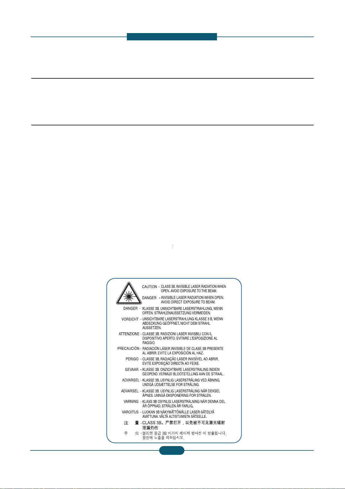
(3) Laser Safety Statement
The Printer is certified in the U.S. to conform to th
Subchapter J for Class 1(1) laser products, and el
orming to the requirements of
laser system and printer are designed so there is n
Class I level during normal operation, user mainte
ass I las
for s afety
the equipment please read the precautions listed
them closely.
ce technician.
ngerous. This printer should only be serviced by a
er. Do not make any unauthorized changes or
inter to malfunction and create an electric shock or
requirements of DHHS 21 CFR, chap ter 1
ewhere, it is certified as a Class I laser product coner products are not considered to be hazardous. The
ever any human access to laser radiation above a
ance, or prescribed service condition.
Warning >> Never operate or service the printer with
assembly. The reflected beam, although invisible, can
When using this product, these basic safety pre-cauti
electric shock, and personal injury.
he protective cover removed from Laser Scanner
damage your eyes.
ns should always be followed to reduce risk of fire,
Service Manual
1
1
SAMSUNG ELECTRONICS
Page 11

a
1.2 Caution for safety
i
o
e
w
w
u
p
e
d
(2)
() y p pp p
o
(5)
a
() p g p
f
c
t
c
r
a
cable immediately, do not reuse or repair the dama
a
m
o
p
i
p
c
d
w
e
h
-
t
y sp
yp
cable. Some chemicals can attack the coating on
1.2.1 Toxic material
1. Prec
utions
This product contains toxic materials that could cause
(1) If the LCD control panel is damaged it is possible f
with the skin should be avoided. Wash any splash
doctor. If the liquid gets into the mouth or is swallo
(2) Please keep Drum cartridge and Toner cartridge a
Drum cartridge and Toner Cartridge may be harmf
1.2.2 Electric shock and fire safety
Failure to follow the following instructions could cause
(1) Use only the correct voltage, failure to do so could
electric shock.
Use only the power cable supplied with the printer.
cable to overheat and potentially cause a fire.
(3) Do not overload the power socket, this could lead t
lead to a fire.
(4) Do not allow water or other liquids to spill into the p
paper clips, pins or other foreign objects to fall into
to an electric shock or fire hazard.
Never touch the plugs on either end of the power c
When servicing the printer remove the power plug
(6) Use caution when inserting or removing the power
firmly and pull. The power connector must be inser
overheating possibly leading to a fire.
(7) Take care of the power cable. Do not allow it to be
damaged. Do not place objects on top of the powe
overheat and cause a fire. Exposed cables could c
the power cable, weakening the cover or exposing
(8) Ensure that the power sockets and plugs are not cr
should be repaired immediately. Take care not to c
the machine.
(9) Use caution during thunder or lightning storms. Sa
from the power source when such weather conditi
ower cord if it is still connected to the wall socket
(10) Avoid damp or dusty areas, install the printer in a
machine near a humidifier or in front of an air con
can lead to overheating and cause a fire or cause
(11) Do not position the printer in direct sunlight. This
possibly leading to the printer failing to work prop
(12) Do not insert any metal objects into the machine t
could make contact with a high voltage conductor
llness if ingested.
r the liquid inside to leak. This liquid is toxic. Contac
s from eyes or skin immediately and contact your
ed see a doctor immediately.
ay from children. The toner powder contained in the
l and if swallowed you should contact a doctor.
recautions
lectric shock or potentially cause a fire.
amage the printer and potentially cause a fire or
Use of an incorrectl
overheating of the cables inside the wall and could
rinter, this can cause electric shock. Do not allow
the printer these could cause a short circuit leading
ble with wet hands, this can cause electric shock.
rom the wall socket.
onnector. When removing the power connector, grip it
ed completely, otherwise a poor contact could cause
ome twisted, bent sharply around corners or wise
cable. If the power cable is damaged it could
use an electric shock. Replace the damaged power
cables causing fire and shock risks.
cked or broken in any way. Any such defects
ut or damage the power cable or plugs when moving
sung recommends that this machine be disconnected
ns are expected. Do not touch the machine or the
n these weather conditions.
lean well ventilated location. Do not position the
itioner. Moisture and dust built up inside the machine
parts to rust.
ill cause the temperature inside the printer to rise
rly and in extreme conditions could lead to a fire.
rough the ventilator fan or other part of the casing, it
inside the machine and cause an electric shock.
ecified cable could cause the
Service Manual
1
2
SAMSUNG ELECTRONICS
Page 12

a
1.2.3 Handling Precautions
a
(1) Ensure the printer is installed on a level surface, ca
v
o
u
o
o
u
g
o
t
g
(3) Disconnect printer interface cables and power cabl
u
x
-
The OPC Drum can be irreparably damaged if it e
d
c
o
g
)
C
t
-
supporting its weight. Failure to do so could
p
light
1. Prec
utions
The following instructions are for your own personal s
product.
cause the printer to tip or fall.
(2) The printer contains many rollers, gears and fans.
fingers, hair or clothing in any of these rotating de
(3) Do not place any small metal objects, containers
which if spilled could get into the machine and ca
(4) Do not install the machine in areas with high dust
a humidifier or heater. Damage could be caused t
(5) Do not place candles, burning cigarettes, etc on th
(6) When reinstalling the imaging unit or ITB unit at p
1.2.4 Assembly / Disassembly Preca
Replace parts carefully and always use Samsung par
cable routing before dismantling any part of the machi
Please carry out the following procedures before dism
(1) Check the contents of the machine memory and m
if the main board or network card is replaced.
(2) Ensure that power is disconnected before servicin
(4) Only use approved spare parts. Ensure that part n
temperature rating are correct.
(5) When removing or re-fitting any parts do not use e
plastic.
(6) Take care not to drop any small parts into the mac
(7) Handling of the OPC Drum
Take care not to expose the OPC Drum either to
room lighting. Exposure for as little as 5 minutes
properties and will result in print quality degradati
Remove the OPC Drum and store it in a black ba
working with the Covers (especially the top cover
damage the OPC Drum.
- Take care not to scratch the green surface of OP
If the green surface of the Drum Cartridge is scra
compromised.
fety, to avoid injury and so as not to damage the
of
Take great care to ensure that you do not catch your
ices.
f water, chemicals or other liquids close to the printer
se damage, shock or fire hazard.
r moisture levels, beside on open window or close to
the printer in such areas.
e printer, These could cause a fire.
wer off, perform the OPC-ACR surely.
tions
s. Take care to note the exact location of parts and
ne. Ensure all parts and cables are replaced correctly.
antling the printer or replacing any parts.
ake a note of any user settings. These will be erased
or replacing any electrical parts.
.
mber, product name, voltage, current and
cessive force, especially when fitting screws into
hine.
to
irect sunlight or to fluorescent or incandescent
an damage the surface of the photoconductive
n. Take extra care when servicing the printer.
or other lightproof container. Take care when
open as light is admitted to the OPC area and can
Drum Unit.
ched or touched the print quality will be
.
Service Manual
1-1
3
3
SAMSUNG ELECTRONICS
Page 13

1. Prec
a
u
r
o
w
v
quip
qp
e
h
h
m
-
e
utions
1.2.5 Disregarding this warning may
(1) Be careful with high temperature compone nts.
The fuser unit works at a high temperature. Use ca
cool down before disassembly.
(2) Do not put fingers or hair into the rotating parts.
When operating a printer, keep your hands and hai
motor, fan, etc.).
(3) When moving the printer :
- When transporting/installing the equipment, employ f
- Be sure not to hold the movable parts or units (e.g. th
equipment.
- Be sure to use a dedicated outlet with 110V/220V po
- The equipment must be grounded for safety.
- Select a suitable place for installation. Avoid excessi
sunlight.
- Provide proper ventilation since the equipment emits
- The e
-Be sure to fix and plug in the power cable securely aft
-If you are moving the machine a short distance, you s
(e.g : same building through elevator)
-If you are moving the machine a long distance, you s
& staple unit, tape and disassemble all trays. (e.g :
ment must be installed near the socket outl
cause bodily injury
tion when working on the printer. Wait for the fuser to
away form the rotating parts (Paper feeding entrance,
ur people and be sure to hold the lifting handles.
e control panel, DADF) when transporting the
er input.
e heat, high humidity, dust, vibration and direct
a slight amount of ozone.
et and must be accessible.
r the installation so that no one trips over it.
ould separate the finisher.
ould remove toner & imaging unit, lock scan carrier
oved by truck or so)
1
Service Manual
4
SAMSUNG ELECTRONICS
Page 14

a
1.3 ESD Precautions
d
integrated circuits, some field effect transistors, and se
h
p
n
o
h
m
d
4. Use only an anti
static solder removal device. Som
y
v
s
g
E
d
n
electricity sufficient to damage an ESD
-
chip components
solder removal devices not classified as anti
v
s
1. Prec
utions
Certain semiconductor devices can be easily damage
commonly called “Electrostatically Sensitive (ES) Dev
The techniques outlined below should be followed to
caused by static electricity.
Caution >>Be sure no power is applied to the chassis
1. Immediately before handling a semiconductor com
off any electrostatic charge on your body by touchi
commercially available wrist strap device, which sh
prior to applying power to the unit under test.
2. After removing an electrical assembly equipped wit
such as aluminum or copper foil, or conductive foa
vicinity of the assembly.
3. Use only a grounded tip soldering iron to solder or
“
”
-
static” can generate electrical charges sufficient to
5. Do not use Freon-propelled chemicals. When spra
damage ESDs.
6. Do not remove a replacement ESD from its protecti
Most replacement ESDs are packaged with all lead
or a comparable conductive material.
by static electricity. Such components are
ices” or ESDs. Examples of typical ESDs are:
“”
.
elp reduce the incidence of component damag e
or circuit, and observe all other safety precautions.
onent or semiconductor-equipped assembly, drain
g a known earth ground. Alternatively, employ a
uld be removed for your personal safety reasons
ESDs, place the assembly on a conductive surface ,
, to prevent electrostatic charge buildup in the
esolder ESDs.
“
-
damage ESDs.
ed, these can generate electrical charges sufficient to
e packaging until immediately before installing it.
shorted together by conductive foam, aluminum foil,
7. Immediately before removing the protective shortin
touch the protective material to the chassis or circui
8. Maintain continuous electrical contact between the
until completely plugged or soldered into the circuit.
9. Minimize bodily motions when handling unpackage
the brushing together of clothing fabric and lifting o
.
material from the leads of a replacement ESD,
t assembly into which the device will be installed.
SD and the assembly into which it will be installed,
replacement ESDs. Normal motions, such as
e’s foot from a carpeted floor, can generate static
Service Manual
1
5
SAMSUNG ELECTRONICS
Page 15

2. Product
d
-
Print and Copy speed (Color/Mono)
A9 Dual Core 1GHz
Booklet Finisher(3K)
2. Product description
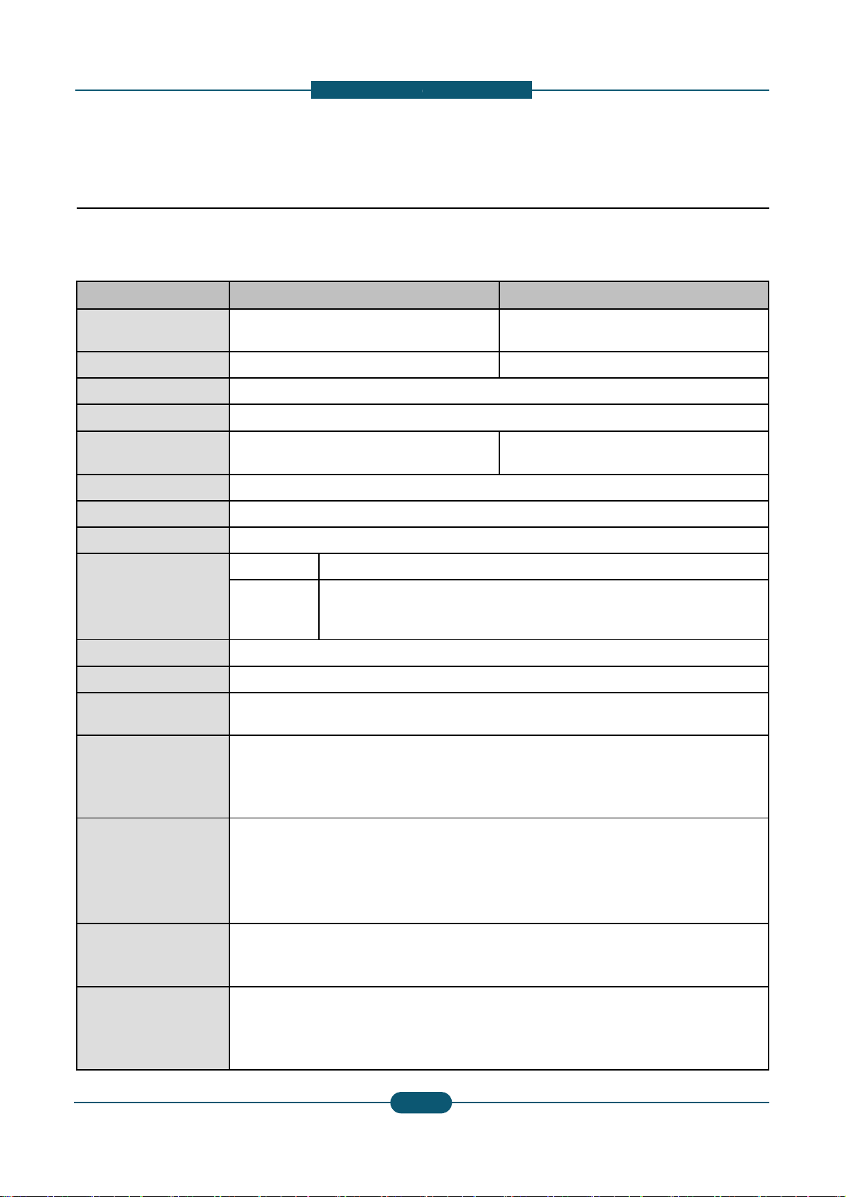
2.1 Specifications
2.1.1 Product Overview
escription
CLX-9252NA : Up to 25 ppmin A4
CLX-9352NA : Up to 35 ppmin A4
Scan Speed
60 ipm @ 300 dpi
CLX-9252/9352 series
Processor
HDD : 320 GB
1.5GB memory
Options
HCF, DCF, Standard Finisher(1K)
, Fax etc.
• 8.9” Full color touch LCD
• XOA(eXtensible Open Architecture) support
Service Manual
2
1
SAMSUNG ELECTRONICS
Page 16
d
2.1.2 Specifications
0
0
c
s
s
W
0
1
W
C
h
2
h
e
-
General Specifications
2. Product
escription
Item CLX-9252NA
Printing Speed (A4)
(Color / Mono)
FCOT (Color / Mono) < 10.6 sec / < 9.0 sec
Warm-up Time < 45 sec from Power Save
Duplex Printing Speed Same as rated engine speed
Scanning Speed (A4)
Memory 1.5GB
HDD 320 GB
CPU
Resolution
Gradation 256
Size (W x D x H ) 675.5 x 722 x 1153 mm (26.6 x
Weight
25 ppm/ 25 ppm
60 ipm @ 300 dpi
40 ipm @ 600 dpi
A9 Dual Core 1GHz
Optical • 600 x 600 dpi
• Draft 600 x 60
Enhanced
96.71 Kg (213.21 lbs.) (without
110 Kg (312 lbs.) (including con
• Default 600 x 6
• Up to 600 x 60
CLX-9352NA
35 ppm/ 35 ppm
< 8.5 sec / < 7.5 sec
60 ipm @ 300 dpi
40 ipm @ 600 dpi
x 1bit
00 x 2 bit
x 4 bit
28.4 x 45.4 inches)
onsumables and options )
umables without options)
Noise (dB)
Power consumption
Power requirement
Power output rating for
heating wire in
DCF/HCF
Service Manual
• Low Power mode : 34 dB(A)
• Ready mode : 43 dB(A)
• Printing mode : 54 dB(A)
• Copying mode : 57 dB(A)
• Average operating mode : Les
• Ready mode : Less than 250
• Low power mode : Less than 5
• Power save mode : Less than
• Power off mode : Less than 0
AC 110-127 V , 50/60 Hz or: A
Note - See the Rating label on t
type of current.
AC 110-127 V , 50/60 Hz or AC
Note - See the Rating label on t
of current.
The voltage rating of heating wir
than 1,100 W
W
1 W
220-240 V , 50/60 Hz
e machine for the correct voltage, frequency (hertz) and
20-240 V , 50/60 Hz
e machine for correct voltage, frequency (hertz) and type
is the same as the machine’s voltage rating.
2
2
SAMSUNG ELECTRONICS
Page 17
d
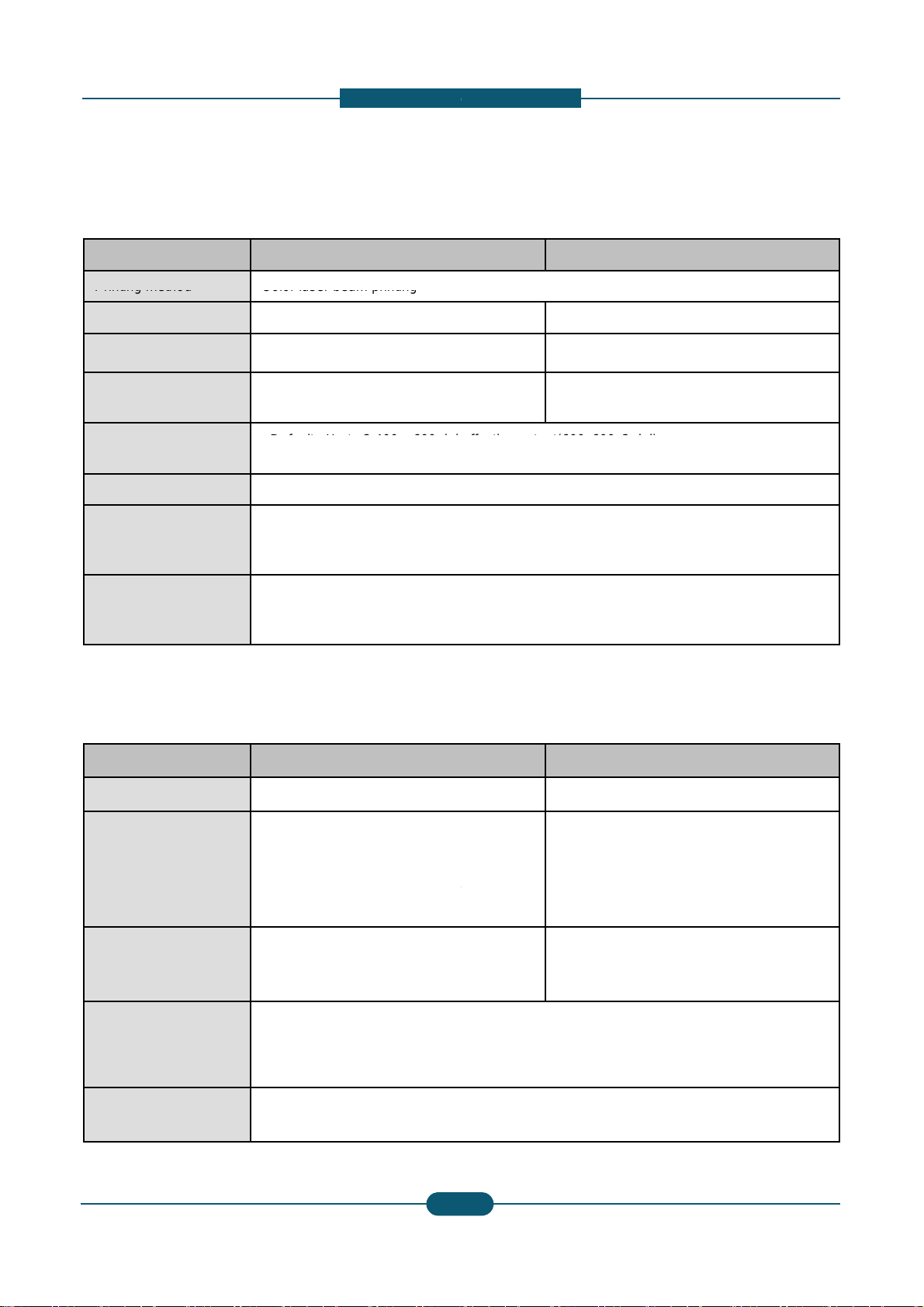
Printer Specifications
Printing method
Color laser beam printing
r
Default
400
600 dpi
e
P
a
.
X
e
e
Duplex copy speed
Duplex to Duplex (2
-
2)
e
6
%
-
t(600x600x2 dpi)
Duplex to Duplex (2
-
2)
2. Product
escription
Item CLX-9252NA
Printing speed Up to 25 ppm (A4), 25 ppm (Lett
Duplex printing speed Up to 25 ipm (A4), 25 ipm (Lette
First print out time
(Color / Mono)
Print resolution
Printer language PCL5Ce, PCL6C, PostScript 3,
OS compatibility
Interface
< 12.2 sec / < 10.6 sec
•
• Max : Up to 9,600 x 600 dpi eff
• Windows: 2000 ,XP,2003 ,Vist
• Various Linux OS
• Macintosh: Mac OS X 10.5~10
• High speed USB 2.0
• Ethernet 10/100/1000 Base T
• FDI (optional)
: Up to 2,
x
Copier specifications
CLX-9352NA
er) Up to 35 ppm (A4), 35 ppm (Letter)
) Up to 35 ipm (A4), 35 ipm (Letter)
< 10.5 sec / < 9.5sec
effective outpu
ctive output(600x600x2 dpi)
DF 1.5+, TIFF, PJL, XPS
,2008 ,Win7
6
(embedded type)
Item CLX-9252NA
Copy Speed Up to 25 cpm (A4), 25 cpm (Lett
Simplex to Duplex (1-2)
: Up to 25 ipm in A4 (25 ipm in L
: Up to 8 ipm in A4 (8 ipm in Lett
@ normal mode
• Black & white: 9.0 seconds
First copy out time
Copy resolution • Platen : 600 x 600 dpi
Zoom range
Service Manual
(from ready)
• Color: 10.6 seconds (from read
• Document feeder: Up to 600 x
• Platen : 25% to 400%
• Document feeder: 25% to 400
CLX-9352NA
r) Up to 35 cpm (A4), 35 cpm (Letter)
Simplex to Duplex (1-2)
y)
2
3
tter)
r)
00 dpi
: Up to 35 ipm in A4 (35 ipm in Letter)
: Up to 22 ipm in A4 (22 ipm in Letter) @
normal mode
• Black & white: 7.5 seconds
(from ready)
• Color: 8.5 seconds (from ready)
SAMSUNG ELECTRONICS
Page 18
d
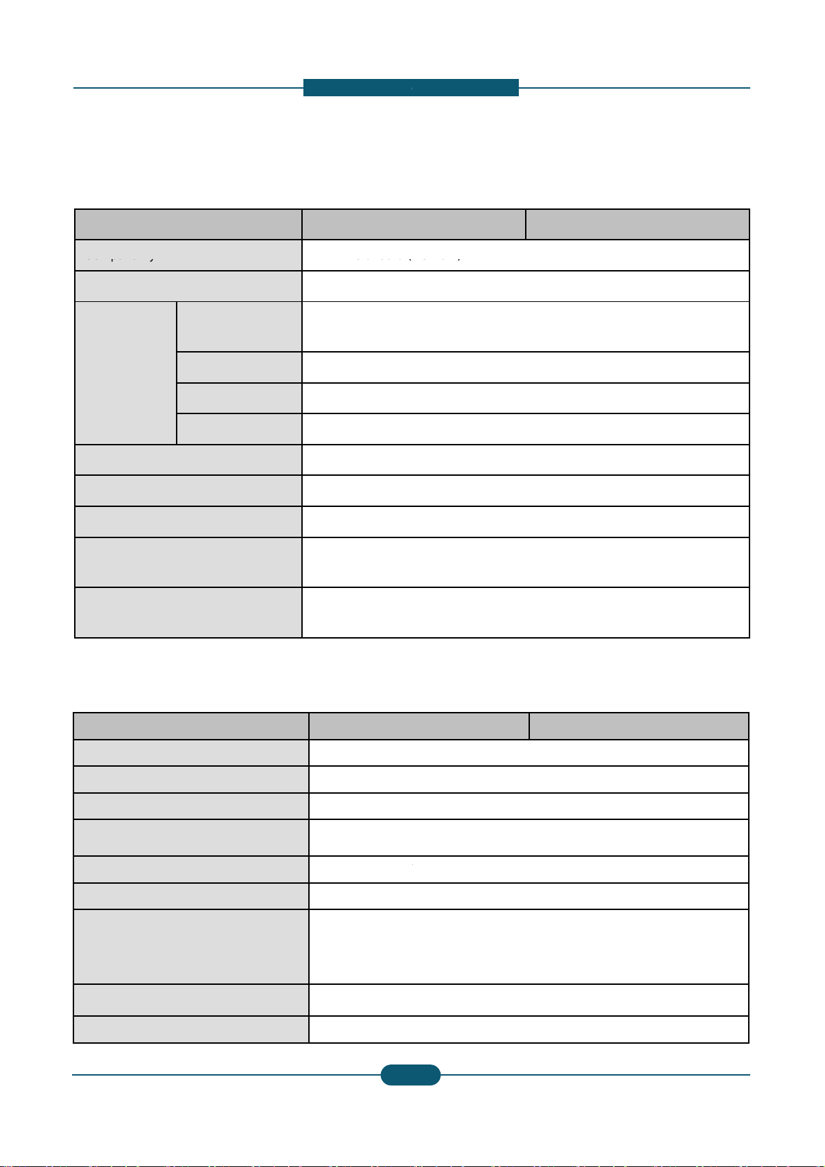
Scanner specifications
Compatibility
TWAIN standard (
p
0
0
0
0
Effecti
idth
M
297
(11
h
e
Applicable line
Public Switched T
/
x
6
-
Network)
7 inches)
Network (PSTN) or behind PABX
x
2. Product
escription
Item CLX-9252NA
Scanning method Color CCD
TWAIN standard
Resolution
Network Scan File format PDF, TIFF, JPEG
Effective scanning length Max. 432 mm (17
ve scanning w
Color bit depth
Mono bit depth
Scan to USB 100, 200, 300, 40
Scan to Email 100, 200, 300, 40
Scan to Server 100, 200, 300, 40
Up to 600 x 600 d
(Up to 4,800 x 4,8
ax.
mm
Internal: 30 bit
External: 24 bit
1 bit for lineart &
8 bit for gray scal
CLX-9352NA
i
0 dpi by software enhancement)
, 600 dpi
, 600 dpi
, 600 dpi
inches)
.
alftone
Fax Specifications
Item CLX-9252NA
Compatibility Super G3
Data coding MH/MR/MMR/JB
Modem speed 33.6kbps
Transmission speed Up to 3 seconds
Maximum document length 356 mm (14 inch
• Standard : 203
Resolution
Memory HDD Backup
Auto dialer up to 500 numbe
Service Manual
• Fine : 203 x 19
• Super Fine : 30
• Ultra Fine : 600
IG/JPEG
page
es)
98 dpi
dpi
0 x 300 dpi
x 600 dpi
rs
2
4
CLX-9352NA
SAMSUNG ELECTRONICS
Page 19

d
Paper Specifications
Input Paper Capacity
040
tte
p
F
.
High Capacity Feeder : A4 /
p
k
a
c
iRec
6
~
4
0
b
-
000 (High C
r
)
100 (MP T
)
Letter
y
2. Product
escription
Item CLX-9252NA
• Standard : 1,040 (Cassette
•Maximum : 1,
Output Paper Capacity
Paper Size
Paper Type
Paper Weight
• Standard : 500 (Center Out
• Maximum : 3,250 (Booklet
• Cassette :
•MP Tray :
•
• Cassette :
Label, CardStoc
• MP Tray :
• High Capacity Feeder :
• Cassette : 60 ~ 216 gsm
• MP Tray : 60 ~ 253 gsm
• High Capacity Feeder : 60
(Casse
148 x 210 mm
98 x 148 mm(3
Plain Pa
Printer Default,
Color Paper, C
Letterhead, Re
er, Th
Pla
(1
(1
CLX-9352NA
1 & 2) + 100 (MP Tray)
1 & 2) + 2,
ut Tray)
inisher)
(5.83”x 8.27”) ~ 305 x 457 mm (12”x 18”)
8”x 5.8”) ~ 320 x 1200 mm (12.6”47”)
in Paper, Bond, Punched, Pre-Printed, Recycled,
, Letterhead, Thick, Cotton, Colored, Archive, Glossy
Plain Paper, Thick Paper, Thin Paper, Bond Paper,
rdStock, Labels, Transparency, Envelope, Preprinted,
cled Paper, Cotton, Archive, Gloss
n Paper, Thin Paper, Bond, Punched, Pre-Printed,
cled, Letterhead,Thick paper
6lb Bond ~ 90lb Index)
lb Bond ~ 90lb Cover)
120 gsm
(16lb Bond ~ 90lb Index)
apacity Feede
+
ray
Original Capacity for DADF 100 sheets
Original Size for DADF
Original Weight for DADF
• Full supported Size : 140 X
• Auto-detected Size : A3, B
• Simplex : 42 ~ 163 gsm (3
• Duplex : 50 ~ 128 gsm (30l
140mm ~ 297 x 432mm (5.5" x 5.5" ~ A3/Ledger)
, B4 SEF, A4, A4 SEF, B5, B5 SEF, A5, A5 SEF
lb Book ~ 90lb Index)
Book ~ 34lb Bond)
Service Manual
2
5
SAMSUNG ELECTRONICS
Page 20

d
Consumables
r
0
0
* Decl
ith 6%
n
a
-
Product
2. Product
Model name
N.A / KOR ELS
escription
Life CLX-9252NA CLX-9352NA
Black Tone
Cyan Toner
Magenta Toner
Yellow Toner
Black Imaging Unit CLT-R607K
Cyan Imaging Unit CLT-R607C
Magenta Imaging Unit CLT-R607M
Yellow Imaging Unit CLT-R607Y
Waste Toner Container CLT-W606
ared yield value in accordance w
CLT-K606S CLT-K60
CLT-C606S CLT-C60
CLT-C607S CLT-C60
CLT-M606S CLT-M6
CLT-M607S CLT-M6
CLT-Y606S CLT-Y60
CLT-Y607S CLT-Y60
patter
** Image counts are based on one color on each pag
Magenta, Cyan, Black), the number of image is 4 im
62S 25K pages O O
62S 20K pages
72S 15K pages O O
62S 20K pages
72S 15K pages O O
62S 20K pages
72S 15K pages O O
75K pages O O
75K pages O O
75K pages O O
75K pages O O
75K images O O
X (Not
Available)
X (Not
Available)
X (Not
Available)
e. If you print a document in full color (Yellow,
ges.
O
O
O
Service Manual
2
6
SAMSUNG ELECTRONICS
Page 21

d
m
Option Unit
0
0
5
5
CLX-HPU001
2-4
r
Fax Kit
CLX-FAX160
G3
c
u
a
0
H
0
of H
-
Hol
(EU)
37/38, PC Fax SW, Fax Manual Softcopy
Wire is the same as the machine s voltage rating)
2. Product
escription
Option Unit Model name Re
Stand CLX-DSK10T
Dual Cassette Tray CLX-PFP000 52
HCF
(High Capacity Feeder)
Bridge Unit CLX-BRG200
Standard Finisher CLX-FIN40S 1,2
Booklet Finisher CLX-FIN40L 3,2
Punch Kit
Working Table CLX-WKT000
Foreign Device Interface
(FDI) Kit
CLX-HCF102 2,0
CLX-HPU000 2-3
CLX-KIT10F Se
ark
Sheet Tray x 2
0 Sheets (LTR, A4)
0 Stacking, Stapling (4 Pos)
0 Stacking, Stapling (4 Pos), Booklet
Holes (NA)
es
ial Port
Fax Multiline Kit CLX-FAX260 G3
SmarThru Workflow Do
CounThru2 Co
Advanced PDF Kit Se
CLX-DHK11C
Heating wire for Cassette,
HCF, DCF
CLX-DHK12C
11
of
22
,
T.
ument Distribution Solution
nter and Cost Management Solution
rchable PDF, Barcode, etc.
V, 10W (equipped by service person at field, voltage rating
eating Wire is the same as the machine’s voltage rating)
V, 10W (equipped by service person at field, voltage rating
’
Service Manual
2
7
SAMSUNG ELECTRONICS
Page 22
d
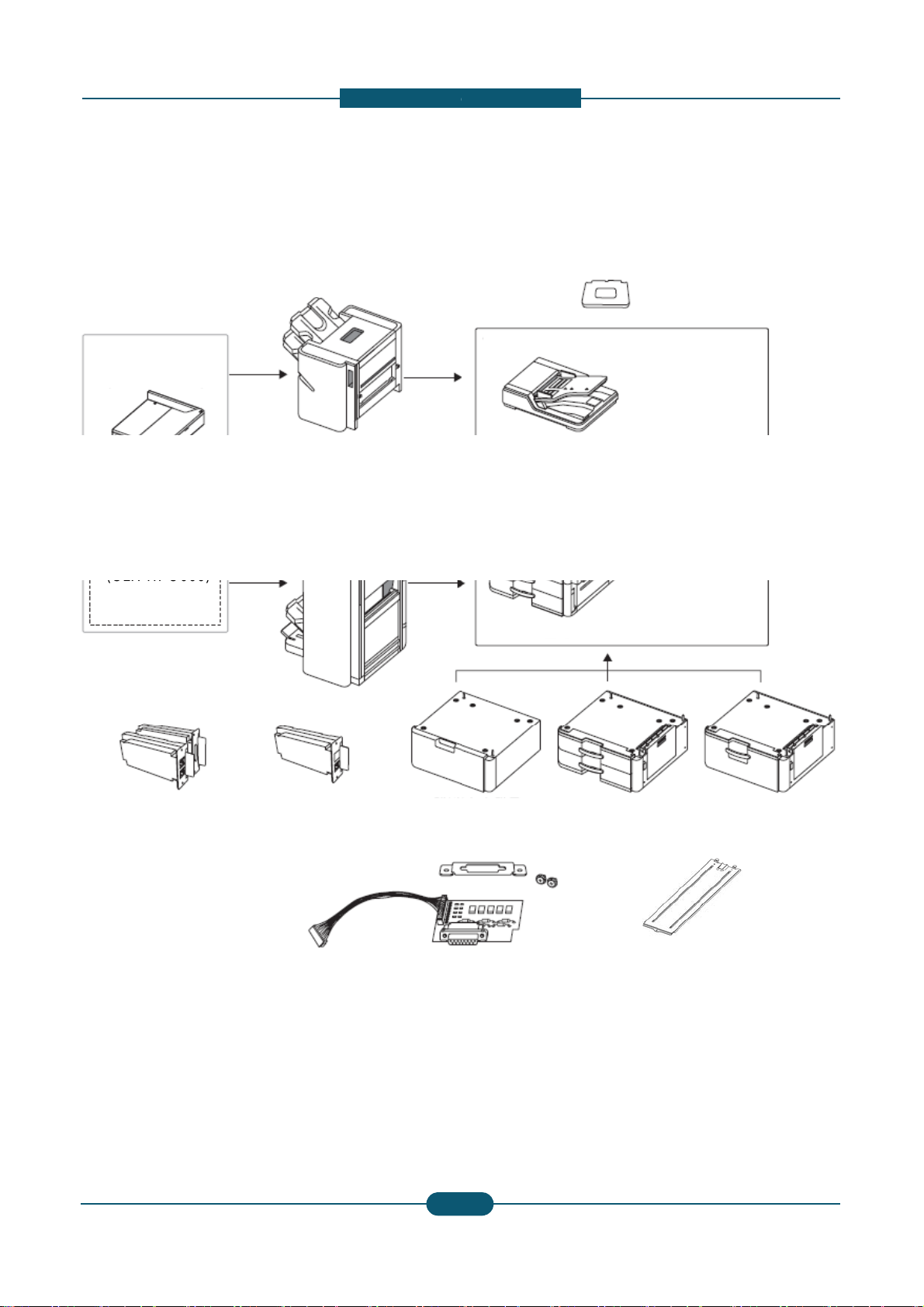
Option unit configuration
(CLX
FIN40S)
(CLX
HPU000)
D
D
X
-
1,250-sheet standard finisher
Bridge kit
(CLX-BRG200)
3,250-sheet booklet finisher
(CLX-FIN40L)
2. Product
escription
Working Table
(CLX-WKT000)
-
Duplex Automatic Document Feeder
2/3 hole Punch kit
-
2/4 hole Punch kit
(CLX-HPU001)
Fax kit
(CLX-FAX160)
Fax multi-line kit
(CLX-FAX260)
(CLX-
(CL
St
and
SK10T)
F
I kit
-KIT10F)
Main unit
(CLX-PFP000)
Optional tray
Cassette Heating cable
(CLX-DHK11C/12C)
High capacity feeder
(CLX-HCF102)
Service Manual
2
8
SAMSUNG ELECTRONICS
Page 23

2. Product
d
C
p
Job seperator
SCX-JST000
X
-
y
XOO
escription
Cosmos / Cosmos-R Option Unit Com
Item Model
Stand CLX-DSK10T O
DCF CLX-PFP000 O
HCF CLX-HCF102 O
Bridge Unit CLX-BRG200 O
1K Finisher CLX-FIN40S O
3K Finisher CLX-FIN40L O
CLX-HPU000 O
Punch Kit
CLX-HPU001 O
Staples Cartridge SCX-STP000 O
Working Table CLX-WKT000 O
FDI Kit CLX-KIT10F O
CLX-FAX150 O
Fax Kit
CLX-FAX160 X
CLX-9250/9350
(Cosmos Color)C(
atibilit
LX-9252/9352
osmos-R Color)
OOO
OOO
OOO
OOO
OOO
OOO
OOO
OOO
OOO
OOO
OOO
XOX
OXO
SCX-8030/8040
(Cosmos Mono)
SCX-8230/8240
(Cosmos-R Mono)
Fax Multi Kit
Heating Wire
for HCF, DCF
Heating Wire
for Scan
CLX-FAX250 O
CLX-FAX260 X
CLX-DHK11C O
CLX-DHK12C O
CLX-DHK11S O
CLX-DHK12S O
XOX
OXO
OOO
OOO
XOX
XOX
Service Manual
2
9
SAMSUNG ELECTRONICS
Page 24
2. Product
d
1
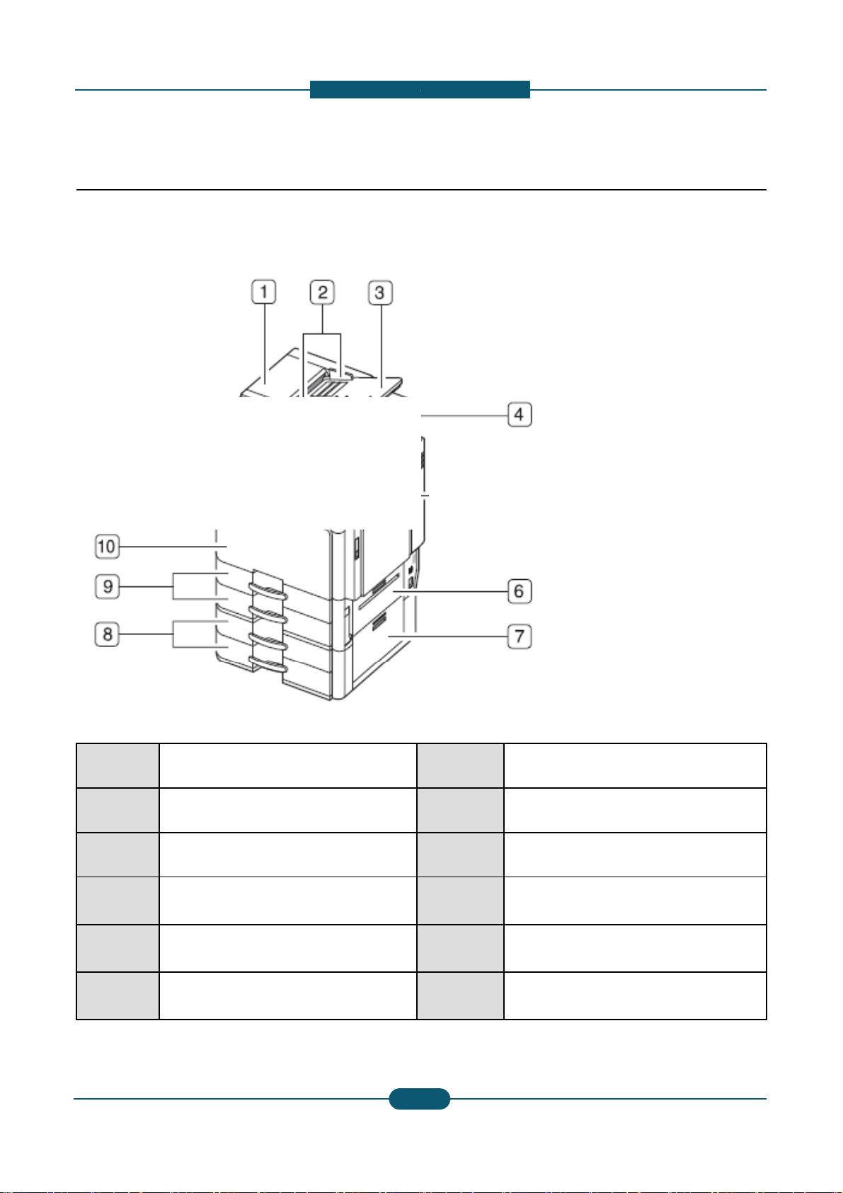
2.2 System configuration
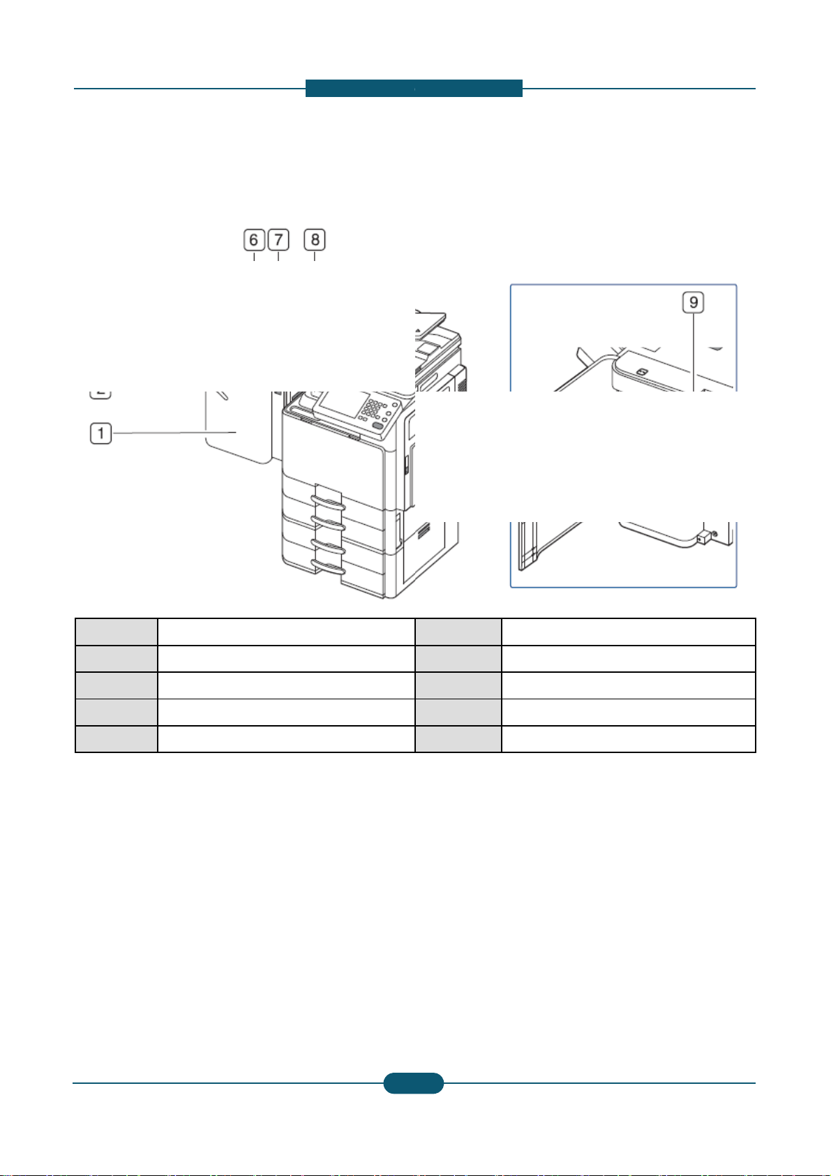
Front view 1
escription
1
2
3
4
6 Standard tray right bottom door
7
Service Manual
Duplex automatic document feeder
cover
Duplex automatic document feeder
width guides
Duplex automatic document feeder
input tray
Duplex automatic document feeder
output tray
Optional dual cassette feeder right
bottom door
8
9 Standard tray (tray 1, tray 2)
10 Front door
11 Front door hand le
12 Contro l panel
13 Cente r tray
2-
0
Optional dual cassette feeder (tray 3,
tray 4)
SAMSUNG ELECTRONICS
Page 25
d
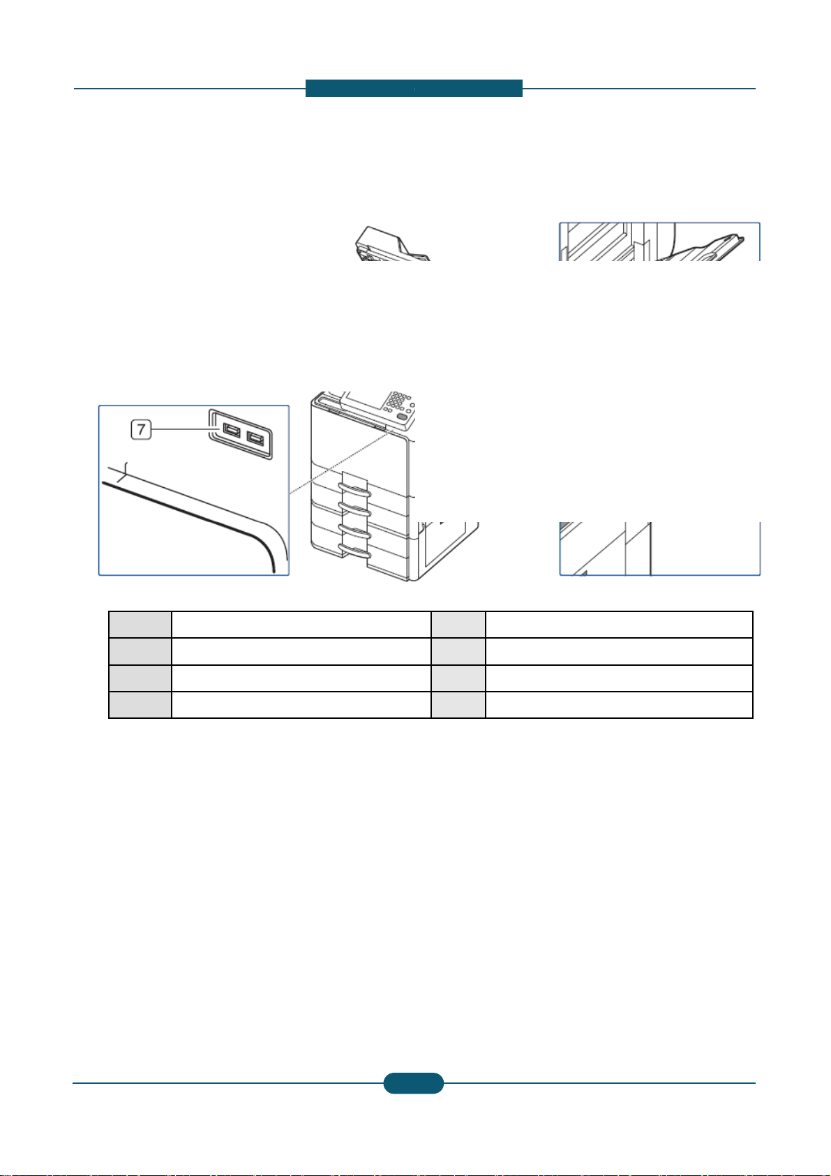
Front view 2
2
White sheet
1
6
Power receptacle
2. Product
escription
1 Scanner glass
3 Multi-purpose tray
4 Multi-purpose tray paper width guide
5 Power-switch
7 USB port (2 EA)
Service Manual
2-
1
SAMSUNG ELECTRONICS
Page 26

d
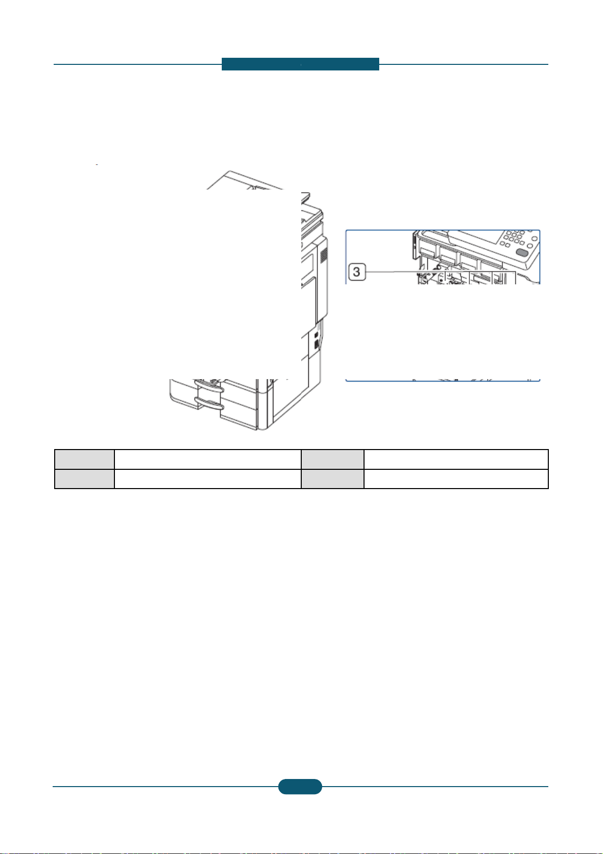
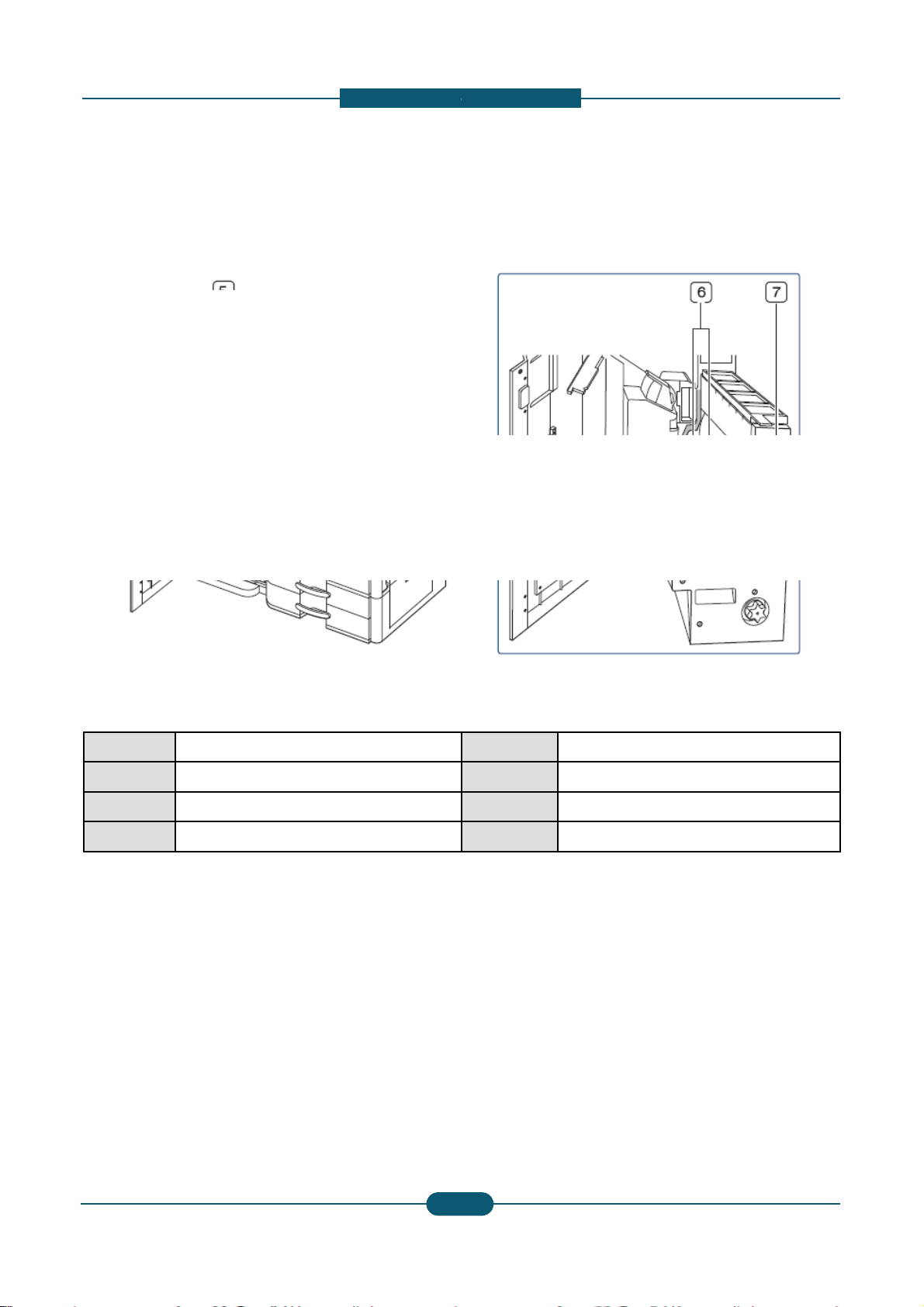
Rear view
1
2. Product
escription
4
1 Optional dual cassette feeder cable
2 DADF cable
3 Scanner locking screw
6
5
4 USB host port
5 Finisher connector
6 Network port
2-
Service Manual
2
SAMSUNG ELECTRONICS
Page 27
d
Inner view
1
2. Product
escription
1 Waste toner container
2 Toner cartridge
3 Imaging units
4 Inner cover
2-
Service Manual
3
SAMSUNG ELECTRONICS
Page 28
2. Product
d
V
1
escription
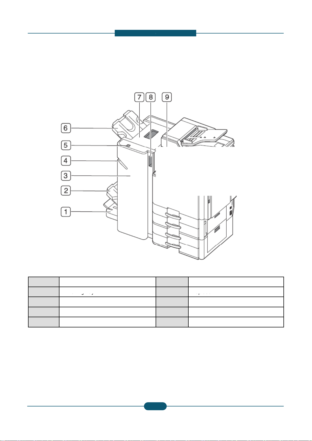
iew with standard finisher (option
al)
1 Standard finisher front door
2 Manual stapler
3 Manual stapler button
4 Finishing tray
5 Top tray
6 Top door
7 Standard finisher Front door handle
8 Bridge Unit
9 Staple
Service Manual
2-
4
SAMSUNG ELECTRONICS
Page 29
2. Product
d
a
2
Finishing tray
1
7
Top door
escription
View with booklet finisher1 (option
l)
1 Booklet tray
3 Booklet finisher front door
4 Manual stapler
5 Manual stapler button
Service Manual
6 Top tray
8 Booklet finisher front door handle
9 Bridge Unit
2-
5
SAMSUNG ELECTRONICS
Page 30
2. Product
d
a
1
escription
View with booklet finisher2 (option
l)
1 Knife wheel
2 Booklet maker handle
3 Fold wheel
4 Booklet jam removal wheel
5 Staple
6 Booklet Staple (2 EA)
7 Booklet maker cover
2-
Service Manual
6
SAMSUNG ELECTRONICS
Page 31

2. Product
d
p
y
pg
y
a
/
d
1
y
15
escription
Layout
1
2
3
4
5
6
7
17
16
14
13
12
8
9
1 DADF 7 Laser s
2 Du
3 Output tray 9 2ndtray
4 Toner cartridges 10 Option
5 Image Transfer Belt
lex guide 8 1sttra
11 Pick up
(ITB) unit
(Stand
Forwar
11
10
canning unit 13 2ndtransfer roller unit
14 Fuser unit
15 Flatbed scanner
l tray
HCF / DCF)
/ Retard /
rollers
16 Document output tray
17 Document input tray
Service Manual
6 Imaging units 12 MP tra
2-
7
SAMSUNG ELECTRONICS
Page 32

d
o
Paper Path
D
Finisher
1
Simplex
2. Product
escription
The following diagram displays the path the paper foll
path
ws during the printing process.
ADF
path
path
Duplex
path
Service Manual
2-
8
SAMSUNG ELECTRONICS
Page 33

d
2.3 Sensor location
a
S1
PBA SENSOR ACR
S7
PHOTO
INTERRUPTER
1
JC32
00012A
JC92
02580A
0604
001393
2. Product
escription
The following diagrams display the printer sensor loc
tions.
Ref. Description
S3 SENSOR-HUMIDITY
S4 PBA SENSOR ACR
S5 PBA SENSOR ACR
S6 SWITCH FRONT COVER
S8 PHOTO-INTERRUPTER
S9 PHOTO-INTERRUPTER
S10 PHOTO-INTERRUPTER
S11 PHOTO-INTERRUPTER
S12 SENSOR-PAPER SIZE
Service Manual
Part
Number
Controller PCB
JC32-00005A
JC32-00012A
JC32-00012A
JC32-00012A
-
0604-001393
0604-001393
PBA-MAIN
CLX-9352NA
:
-
CLX-9252NA
: JC92-02581A
0604-001393
0604-001393
JC32-00013A
2-
9
SAMSUNG ELECTRONICS
Page 34

2. Product
d
S17
PHOTO
INTERRUPTER
2
S23
SENSOR
DEVELOPER
: JC92
02580A
0604
001370
PBA
MAIN
Part
A
JC32
00010A
escription
Ref. Description
S13 SENSOR-PAPER SIZE
S14 SENSOR-HUMIDITY
S15 PBA-COVER OPEN SENSOR
S16 PHOTO-INTERRUPTER
-
S18 PHOTO-INTERRUPTER
S19 CCD
Part
Number
JC32-00013A
JC32-00005A
JC92-02143A
0604-001393
-
0604-001370
0605-001158
Controller PCB
PBA-MAIN
CLX-9352NA
-
CLX-9252NA
: JC92-02581A
PBA-SCAN JOINT
(JC92-02144A)
-
CLX-9352NA
: JC92-02580A
CLX-9252NA
: JC92-02581A
Service Manual
Ref. Description
S20 SENSOR-DEVELOPER
S21 SENSOR-DEVELOPER
S22 SENSOR-DEVELOPER
-
Number
JC32-00010A
JC32-00010A
JC32-00010A
-
2-
0
Controller PCB
PBA-MAIN
CLX-9352NA
: JC92-02580A
CLX-9252N
: JC92-02581A
SAMSUNG ELECTRONICS
Page 35

2. Product
d
2
CLX-9252NA
escription
Ref. Description
S31 PHOTO-INTERRUPTER
S32 PHOTO-INTERRUPTER
S33 PHOTO-INTERRUPTER
S34 PHOTO-INTERRUPTER
S35 PHOTO-INTERRUPTER
S36 PHOTO-INTERRUPTER
S37 PHOTO-INTERRUPTER
Service Manual
Part
Number
Controller PCB
0604-001393
0604-001393
PBA-ENGINE
0604-001393
CLX-9352NA
0604-001393
: JC92-02129A
0604-001381
0604-001393
: JC92-02239A
0604-001393
2-
1
SAMSUNG ELECTRONICS
Page 36

2. Product
d
S40
PHOTO
INTERRUPTER
S
2
0604
001393
0604-001399
escription
Ref. Description
S38 PHOTO-INTERRUPTER
S39 PHOTO-INTERRUPTER
S41 PHOTO-INTERRUPTER
S42 PHOTO-INTERRUPTER
S43 PHOTO-INTERRUPTER
S44 PHOTO-INTERRUPTER
45 PHOTO-INTERRUPTER
S46 PHOTO-INTERRUPTER
S47 VR-SLIDE
S48 PHOTO-INTERRUPTER
S49 PHOTO-INTERRUPTER
S50 PHOTO-INTERRUPTER
S51 PHOTO-INTERRUPTER
Part
Number
0604-001393
0604-001393
0604-001393
0604-001393
0604-001393
0604-001393
0604-001381
2102-001020
0604-001393
0604-001381
0604-001393
0604-001393
Controller PCB
PBA-MAIN
CLX-9352NA
: JC92-02580A
CLX-9252NA
: JC92-02581A
S52 PHOTO-INTERRUPTER
S53 PHOTO-INTERRUPTER
S54 PHOTO-INTERRUPTER
S55 PHOTO-INTERRUPTER
0604-001393
0604-001381
0604-001393
0604-001393
Service Manual
2-
2
SAMSUNG ELECTRONICS
Page 37

2. Product
d
u
e
s
p
p
Tray1 paper
motor
2
T
e
e
T2
Tray2 upper limit detection
2.4 Paper handling section
escription
The paper feeding system mainly consists of the Pick
Registration roller, MP Paper sensor, Paper Empty s
Tray Feed sensor, Registration sensor, and Drive sy
Return
Exit tray1 paper
full detection
Exit tray1 jam detection
Return
Paper jam detection
Paper curl detection
ath solenoid
Exit
Fuser
p roller, Forward roller, Retard roller, Transport roller,
nsor, Tray Paper Stock sensor, MP Feed sensor,
tem for these components.
Exit2 tray path solenoid
Exit tray2 paper
full detection
Duplex jam detection1
Duplex
Paper regi. time detection
Tray1 paper remaining
quantity detection
Tray1 paper
empty detection
Paper tray
size detection
Tray2 paper
empty detection
Tray2 paper
size detection
Service Manual
ITB
Regi
MPF solenoid
Tray1 upper limit detection
Tray1 lift
Tray2 lift
motor
ray2 pap
quantity d
Pick Up
r remaining
tection
2-
3
Duplex jam detection2
Duplex clutch
MPF
clutch
MPF paper
empty
detection
MPF media size detection
Tray1 transport detection
Tray2 transport detection
MPF
MPF media
size detection
(Long media)
SAMSUNG ELECTRONICS
Page 38

2. Product
d
s
r
Tray1 paper empty detection
Detects tray1 paper e
i
p
s
r
T
Detects t
e
i
p
T
o
Paper jam detection
Detects fuser jam
MPF solenoid
MPF pick up roller up
s
s
o
Duplex jam detection 2
Detects duplex jam 2
p
e
e
e
2
y
CN4@ Cassette Joint PBA, 3Pin
y
ty
CN4@ C
PBA, 3Pi
CN5 @ SIDE JOINT PBA, 3PIN
CN2 @ SIDE JOINT PBA, 3PIN
CN6 @ SIDE JOINT PBA, 3PIN
y
escription
Name Funct
Tray1 paper size detection Detects tray1 paper
Tray1 paper remaining quantity
detection
Detects tray1 paper
Tray1 upper limit detection Detects tray1 upper l
Tray1 transport detection Detects tray1 paper
Tray2 paper size detection Detects tray2 paper
Tray2 paper remaining quantity
detection
ray2 paper empty detection
Detects tray2 paper
ray2 paper
Tray2 upper limit detection Detects tray2 upper l
Tray2 transport detection Detects tray2 paper
Paper regi. time detection Detects paper regi.
Paper curl detection Detects paper positi
Face down tray jam detection Detects exit jam
Face down tray paper full
detection
Detect paper full
Exit2 tray path solenoid Change paper path
ion connector & pin information
ize (installation) CN2@ Cassette Joint PBA, 4Pin
emaining quantit
CN8@ Cassette Joint PBA, 6Pin
mit CN3@ Cassette Joint PBA, 3Pin
ass CN3@ Cassette Joint PBA, 3Pin
ize (installation) CN2@ Cassette Joint PBA, 4Pin
emaining quantit
mp
CN8@ Cassette Joint PBA, 6Pin
assette Joint
n
mit CN3@ Cassette Joint PBA, 3Pin
ass CN3@ Cassette Joint PBA, 3Pin
ime CN18@ Engine PBA, 3PIN
n CN5@ SIDE JOINT PBA, 6PIN
CN18@ Engine PBA, 3PIN
CN18@ Engine PBA, 3PIN
CN8 @ SIDE JOINT PBA, 3PIN
Return path solenoid Change paper path
MPF media size detection Detects MPF paper
MP media size detection
(Long media)
Detects MPF paper
MPF clutch MPF driving control
Duplex clutch Duplex driving contr
Duplex jam detection 1 Detects duplex jam 1
Exit tray 2 paper full detection Detects exit tray2 pa
MPF Paper empty detection Detects MPF paper
Tray1 Lift Motor Lifting knock up plat
Tray2 Lift Motor Lifting knock up plat
CN18@ Engine PBA, 3PIN
ize CN7 @ SIDE JOINT PBA, 3PIN
ize CN7 @ SIDE JOINT PBA, 3PIN
CN2 @ SIDE JOINT PBA, 2PIN
l CN4 @ SIDE JOINT PBA, 2PIN
CN6 @ SIDE JOINT PBA, 3PIN
er full CN6 @ SIDE JOINT PBA, 3PIN
mpt
CN7 @ SIDE JOINT PBA, 3PIN
CN4@ Cassette Joint PBA, 3Pin
CN4@ Cassette Joint PBA, 3Pin
Service Manual
2-
4
SAMSUNG ELECTRONICS
Page 39

d
2.4.1 Components
i
2
25
forward rollers
19
13
Tray 4 feed roller
full
2. Product
escription
The following diagrams display the positions of the pr
22
23
21
nter components
24
20
16
14
17
18
15
1 Tray 1 Paper tray
2 Tray 2 Paper tray
3 Tray 3 Paper tray
4 Tray 4 Paper tray
5 Tray 1 pick up / retard /
6 Tray 2 pick up / retard /
forward rollers
7 Tray 3 pick up / retard /
forward rollers
8 Tray 4 pick up / retard /
forward rollers
9 MP Tray pick up /
retard / forward rollers
10 Tray 1 feed roller
11 Tray 2 feed roller
12 Tray 3 feed roller
14 Bypass feed roller
9
10
1
5
11
2
6
12
7
15 Sensor registration
16 Roller registration
nd
17 Roller 2
18 Sensor fuser in
19 Roller fuser
20 Sensor fuser out
transfer
3
13
8
21 Roller exit
22 Roller face down exit
4
23 Actuator face down bin
24 Sensor duplex return
25 Roller duplex return
Service Manual
2-
5
SAMSUNG ELECTRONICS
Page 40

d
d
2.4.2 Functions
Pickup Roller (paper tray and bypass feed)
o
Retard Roll
d)
d
e
d
yg (pp y yp
e
a
e
This sensor detects whether paper is set in the bypass
o
a
d
c
Feed Sensor
e
r
r
2
)
tray
When it is, bypass feeding always comes
2. Product
escription
This section describes the functions of the paper han
This roller moves up and down and draws out the pap
the feed roller.
Forward Roller (paper tray and bypass feed)
This roller is placed against the retard roller. It transp
transport roller.
er (paper tray and bypass fee
This roller is placed against the feed roller. When two
pickup roller, the load of the torque limiter of the retar
sheets. As a result, the retard roller is stopped and th
only one sheet is transported from the pickup roller, th
roller.
Conveying Roller (paper tray and bypass fee
This roller transports the paper sent from the feed roll
Registration Roller
Paper transported from the transport roller is pushed
edge of the paper. Then, the registration rollers rotat
ling components.
er from the bypass tray or drawer and transports it to
rts the paper from the pickup roller to the
sheets of paper or more are transported from the
roller is heavier than the frictional force between the
lower paper does not advance any further. When
e retard roller rotates following the feed
r to the registration roller.
gainst the registration roller which aligns the leading
to transport the paper to the transfer unit.
Bypass Paper Sensor
before drawer feeding.
Empty Sensor (Tray 1 / Tray 2)
This is a transmissive-type sensor and it detects the a
When there is no paper in the drawer, the actuator bl
determines that there is no paper.
Paper Stock Sensor
This is a transmissive-type sensor which detects the
actuator. When the remaining paper is consumed an
blocks
the light path for the transmissive-type sensor to dete
This sensor detects if the leading edge or trailing edg
detects jamming such as missfeeding.
Registration Sensor
This sensor detects that the leading edge of the pape
trailing edge of the paper has passed the registration
.
vailability of paper in the drawer by using an actuator.
cks the light path of the sensor, and the sensor
mount of remaining paper in the drawer using an
approximately 100 sheets remain, the actuator
t that there is less paper.
of the paper has passed the feed roller. It also
has reached the registration roller and that the
oller.
Service Manual
2-
6
SAMSUNG ELECTRONICS
Page 41

d
2.4.3 Paper tray
e
p, pp
A
m
•
Paper
:
7
s
o
2
2. Product
escription
The paper trays consist of the Main trays, Optional tra
The MP tray is located on the right side of the machin
envelopes, and custom size paper.
Paper size is set using the Size Guides in each tray.
paper size.
ys (DCF,HCF), and one Multi-Purpose (MP) tray.
and allows feeding of specialty media stock,
djust the Front, Rear, and End Guides to match the
Specification
• Structure : Paper tray Type, Auto Paper Size
• Capacity : 520 Sheets ( 80g/㎡ standard Xerox Pre
-. Plain paper : A5, A4, A3, B5, B4, Letter, 11"×1
-. Special Paper : 12"×18", Label, Card stock
• Weight : plain paper 60 ~ 216g/㎡
• Plate knock up Lift type : Lift Motor + Up Limit Sens
Service Manual
inum)
"(Ledger), Statement, Legal
(Label : 50 sheets, Thick Card
tock [170~216 g/㎡ : 350 sheets)
r
2-
7
SAMSUNG ELECTRONICS
Page 42

d
2.4.4 Pick up unit
w
o
roller serve to make sure that a single sheet of paper i
c
2
s moved to the paper path, and the paper is moved
2. Product
escription
When pickup takes place, the pickup roller moves do
The pickup roller moves down when the pickup solen
as far as the registration roller by the work of the verti
pickup roller:
Actuator-Empty Sensor
n to come into contact with the surface of the paper.
id is activated. The forward roller and the retard
al path roller. The following is a diagram of the
Forward Roller
Retard Roller
Pick Up Roller
Service Manual
2-
8
SAMSUNG ELECTRONICS
Page 43

d
t
l
2.4.5 Registration unit
roller in order to match paper and an image on the dru
a
■
Specification
F
F
Duplex Side Margin
±
2.0 mm
Tray3
2
the predetermined registration point
HCF : 4.23
±
2.0 mm )
2. Product
escription
The registration roller is driven by the registratio n mul
between the registration roller and the registration mu
Sh
Jam removal lever
Regi sensor
i motor. The registration clutch (CL6) is located
ti motor, and it controls ON/OFF of the registration
at
.
ft-regi
Regi roller
Transparency
detection sensor
1) Skew in Simplex
-. Top Skew : 1.5 mm
-. Side Skew : 2.0 mm
2) Dog Ear, Trees, Nicks, Wrinkling
-. Special Media : 1/500
3) Margin
-. Top Margin : 4.23 ± 1.5 mm ( Tray3, 4, HC
-. Side Margin : 4.23 ± 1.5 mm ( Tray3, 4, HC
-. Duplex Top Margin : 4.23 ± 2.0 mm ( Tray3
.
-
: 4.23
(
: 4.23 ± 2.0 mm )
: 4.23 ± 2.0 mm )
, 4, HCF : 4.23 ± 2.0 mm )
, 4,
Service Manual
2-
9
SAMSUNG ELECTRONICS
Page 44

d
2.4.6 MPF unit
P
n
g sp
L
gp
pp (
), pp (
n
3
MPF Clutch
g)
)(ggg)
The following is a diagram of the MFP unit:
MPF Pick up roller
Empty sensor
MPF
Tray
2. Product
escription
Long paper sensor
Specification
• Tray capacity : 100 sheets( 80g/㎡ standard Xerox
• Media Size : Max 12.6”×17.7” (320.6×450㎜) / Mi
• Media weight : Plain paper 60 ~ 253g/㎡
• Feedin
eed : 30 ppm (CLX-9352NA), 20 ppm (C
•Auto size sensing : A6 SEF, Statement SEF, B5 S
LTR(Letter) LEF, A3, A4 LEF
Paper Separation
When the by-pass paper detection [A] sensor detects
the by-pass solenoid [B] drops the pick-up roller [C] o
After that, the pick-up roller moves one
sheet of paper to the feed roller.
This machine uses an FRR (Feed and
Reverse Roller) system for feeding paper.
There is friction between the feed roller [E]
and retard roller [D]. This friction separates
the top sheet of paper from the stack.
reminum )
3.87”×5.8” (98×148㎜)
X-9252NA) in Letter/A4 LEF (Long Edge Feedin
EF, A4 SEF, A5 LEF, B4 B5(JIS) LEF, 11x17,
paper and the machine gets a by-pass printing job,
to the top of the paper stack on the by-pass tray.
Service Manual
2-
0
SAMSUNG ELECTRONICS
Page 45

d
2.5 Image creation
v
e
M
a
a
b
of a Drum unit and Development unit
Each Drum unit
n
d
g
o
iti
s
h
h
e
e
p
r
3
r
C
a
has an OPC drum, Charge
Scorotron
Eraser and
[E]
2. Product
escription
This section describes the image creation process us
2.5.1 Printing process ov er
This color printing system includes the LSU with four l
unit. The 4 imaging units are: Yellow, Magenta, Cyan
d by the printer.
iew
Paper path
ser beams, four imaging units, ITB unit and transfer
nd Black (from left to right as shown in the diagram).
This machine uses four Imaging units, and four laser
.
Cleaning blade. From the left, the Imaging unit statio
The OPC drum [A] is charged with a negative voltage
from the LSU (Laser Scanning unit) [B]. The light pro
discharging on the surface of the OPC drum. The ne
image due to an electric field. The toner (real image)
the positive bias applied to the first transfer roller [C].
paper by a pos
Process Steps
1. OPC drum charge: The Charge Scorotron gives t
2. Laser exposure: Light produced by a laser diode
3. Development: This machine uses a dual-compon
negatively charged toner to the latent image on th
imaging units (one for each color).
4. Transfer:
a. First transfer: The first transfer rollers op
the transfer belt. Four toner images are supe
ve charge applied to the second tran
eams for color printing. Each Imaging unit consists
s are: yellow, cyan, magenta, and black.
by the Charge Scorotronand is exposed by the light
uced by the laser creates a latent image by
atively charged toner is attracted to the latent drum
n each OPC drum is moved to the transfer belt by
All four toners (color image) are transferred to the
er roller
e drum a negative charge.
its the charged OPC through the lens and mirrors.
nt development system. The magnetic roller carries
drum surface. This machine uses four independent
osite the OPC drums transfer toner from the drums to
-imposed onto the belt.
.
,
b. Second transfer: The transfer roller transfe
Service Manual
s the toner from the transfer belt to the media.
2-
1
SAMSUNG ELECTRONICS
Page 46

2. Product
d
b
a
v
D
n
s
p
pg
o
3
escription
5. Cleaning for OPC drum: The cleaning brush and
after image transfer to the paper.
6. Quenching for OPC drum: Quenching is done by i
at the end of every job.
7. Cleaning and quenching for transfer belt: The cle
grounding roller inside the transfer belt unit remo
lade remove remaining toner on the drum surface
lluminating the whole area of the drum with the laser
ning brush and blade clean the belt surface. The
es the remaining charge on the belt.
8. ID sensors: The ID sensors detect the density of I
sensors for the line position adjustment (front, ce
[A]: Line position adjustment (front)
[B]: Line position adjustment (center) & proce
[C]: Line position adjustment (rear)
[D]: Humidity Sensor (Internal).
The ID sensor out
ut is used for the following:
- Process control and for automatic line positi
- Skew correction
- Color registration adjustments for the latent i
sensor patterns on the transfer belt. Three ID
ter, and rear) and process control.
s control
n
mage.
2-
Service Manual
2
SAMSUNG ELECTRONICS
Page 47

d
2.5.2 Imaging unit
e
b
r
g
b
o
u
u
C
3
2. Product
escription
2.5.2.1 Imaging unit ov ervi
Each Imaging Unit consists of the OPC drum unit and
OPC drum, Charge Scorotron, Eraser, and Cleaning
two mixing augers, developer, and a TD sensor. Fou
(drum unit, development unit, etc.), however, the Ima
The diameter of the drum is 30 mm (circumference: a
The developing gap between a drum and the corresp
they are assembled as one Imaging unit at the factory
The cleaning blade removes excess toner from the dr
The CRUM chip in the image unit stores the data abo
OP
Magnetic Roller
w
the development unit. The OPC drum unit has an
lade. The development unit has a magnetic roller,
color Imaging Units contain identical components
ing Units are not interchangeab le.
out 94.2 mm).
nding magnetic roller cannot be adjusted becaus e
.
m surface after image transfer to the transfer belt.
t the Imaging unit.
Drum
Cleaning blade
Eraser
harge scorotron
Mixing Auger
Service Manual
C
2-
3
SAMSUNG ELECTRONICS
Page 48

d
2.5.2.2 Drum drive
o
Y
e
Phase sync for each OPC
runout
prints the pattern on
K
D
C
3
r
the ITB and is adjusted by the data automatically
r
BLDC motor
2. Product
escription
Each color OPC and Mag Roller is driven by each col
Drive transmission gear
Drum phas
Coupling
Drum-Y
Drum-M
r motor.
senso
M Drum phase senso
C Drum phase sensor
.
K Drum phase sensor
rum-
Coupling OPC
Coupling Deve
Drum-
Drive motor BLDC
Gear-Drive OPC
Service Manual
2-
4
SAMSUNG ELECTRONICS
Page 49

2. Product
d
h
t
o
m
b
g
q
a
A
2.5.2.4 D
t
n
e
n
e
m
3
Mixing
Sensor
[B]
[] g g
escription
2.5.2.3 Phase Control Mec
The printer uses the drum gear position sensors to de
mode shows when it detects that the drum motor is n
initialize the relative positions of the gears when the
prevents phase fluctuation between printouts caused
There is an interrupter on each drum gear. The drum
interrupters. This mechanism makes sure that outp ut
Immediately after the printer power turns on, recovers
opened and closed, the printer executes the drum ph
occurs:
• When a new imaging unit is installed.
• When a new cartridge transfer belt unit is installed.
lso, when the printer detects a shift in the drum posit
executes the drum phase adjustment.
evelopmen
anism
ect whether the drum motors are rotating. Diagnostic
t moving. These sensors also help the printer to
ain switch is turned on, and during initializing. This
y incorrect gear meshing at the start of the job.
ear position sensors detect the positions of these
uality does not vary.
from the energy saver mode, or the front door is
se adjustment if one of the following conditions
ions during the line position adjustment, the printer
[A] Developme
This printer uses a dual-component development syst
the drum units; one for each color). Each new unit co
in each unit is supplied to the magnetic roller [A] by th
surface of the roller. The diameter of the magnetic rol
t Roller
[C] TD
Mixing Auger
m and has four imaging units (which are included in
tains 330g of magnetic toner carrier. The developer
two mixing augers [B] and is attracted onto the
ler is 18 mm.
[B]
Auger
Each imaging unit has a TD(Toner Developer) sensor
controlling the operating range of toner density. The i
information about the imaging unit is stored.
Service Manual
[C]. The TD sensor [C] in the imaging unit is used for
aging unit is equipped with a CRUM in which some
2-
5
SAMSUNG ELECTRONICS
Page 50

2. Product
d
d
h
h
3
escription
Two mixing augers [A] circulate the developer forwar
mix the developer and toner well.
This occurs at the following times:
• During TD calibration
• During development.
Filters [B] on the top of the development unit ensure t
During the operating, this prevents contamination of t
[B] Filter
and backward to agitate the developer in order to
at the internal pressure does not become too high.
e imaging unit by the toner.
[A] Auger
2-
Service Manual
6
SAMSUNG ELECTRONICS
Page 51

2. Product
d
u
s
a
th
iti
is
e
o
8
Paper Transfer Ro
A
3
escription
2.5.3 Cartridge Transfer un
2.5.3.1 Cartridge Transfer
The toner is moved from the four drums to the ITB by
rotation of the ITB (four toner images are super-impo
drums on the diagram shows the direction of ITB rotat
toner image from the transfer belt to the paper. The p
in the transfer unit cleans the belt surface with the cle
collected from the belt is transported to the toner colle
em are for the line pos
6
on adjustment. The other
4
1
2
it
nit overview
the four image transfer rollers. This is done with one
ed onto the belt). The arrow above the C and M
ion. The ITB drive roller then moves the four-colo r
aper transfer roller is an idle roller. The cleanin g unit
ning blade and tension roller. The used toner
ction bottle. There are three ACR sensors. Two of
for process control.
7
3
8
YM
CK
5
9
1
2
3
4
5
6
7
9
Image Transfer B
Image Transfer R
ITB Drive Roller
Tension Roller
Rotation Encoder
Cleaning Blade
ACR Sensor
Toner Collection
lt (ITB)
ller
uger
Service Manual
2-
7
SAMSUNG ELECTRONICS
Page 52

2. Product
d
3
2.5.3.2 T ransfer belt driv e
escription
The ITB drive motor [A] drives the image transfer belt
drive roller [C]. The speed of ITB drive depends on th
[B] and the Cleaning unit by using gears and the ITB
e process line speed.
[B]
[A]
[C]
2-
Service Manual
8
SAMSUNG ELECTRONICS
Page 53

2. Product
d
n
a
iti
lt
T
t
C
3
t cl
hile the i
t
escription
2.5.3.3 T ransfer belt c leani
The ITB-cleaning unit removes toner (during printing)
or automatic line pos
makes one rotation. The ITB drive motor drives the I
The cleaning blade [A] in the cleaning unit always con
toner from the belt. Then the toner collection auger [
container.
The Film [D] on the Cleaning Unit protects against ton
roller is transferred to the tension roller [E]. The Gear
on adjustment) on the belt. Be
[E]
[D]
g
nd the ACR sensor patterns (during process control
eaning is completed w
B-cleaning unit.
acts the image transfer belt [B], and removes used
] transports the toner towards the waste toner
er contamination. The driving power from the drive
[F] drives the Gear [G].
[B]
mage transfer belt
[C]
[A]
[F]
[C]
[G]
[E]
Other Side
Service Manual
2-
9
SAMSUNG ELECTRONICS
Page 54

d
2.6 Fuser unit
d
u
l
2.6.1 Fuser unit overview
h
m
p
c
4
Halogen Lamp
2. Product
escription
This section describes the image fusing process use
A belt fusing system is used. This has a faster warmsystem.
The heating roller is made of a thin steel pipe to quick
fusing roller and pressure roller are made of soft silico
nip. These rollers do not contain a fusing lamp. The
center heating lamp, heats the center and the other la
direction). NC sensors (non-contact type thermistors)
heating roller, control the temperature of the fusing be
ends, respectively.
Two NTC thermistors and two thermostats, located at
system from overheating by the heating lamps. Tem
the center heating lamp and side heating lamp, respe
temperatures.
by the printer.
p time than a conventional fusing and pressure roller
y increase the temperature of the fusing belt. The
ne rubber, which flatten slightly, increasing the fusing
eating roller contains two fusing lamps (one lamp,
p, side heating lamp, heats the ends in the axial
, located near the center and the rear end of the
lt just above the heating roller at the center and the
the center and the front end, protect the fusing
erature is normally controlled by turning on and off
tively, corresponding to predetermined target
Pressure Roller
Service Manual
Fuser Ro
2-
Fusing Belt
Heat Roller
Thermistor
(0.5mm-1.0mm
distance)
Thermostat
ller
NC Sensor
0
SAMSUNG ELECTRONICS
Page 55

2. Product
d
t
L
a
e
g
h
The fuser belt couples the heat roller with the fuser ro
h
r
t
belts easier
The melted toner is soaked into the pap
p
e
h
h
4
conducts heat from the heat roller to the fuser
improve the fusing ability, a fuser roller with
escription
2.6.2 Fuser unit componen
The Fuser unit includes the following components:
1. Center heater lamp (LAMP1) / Side heater lamp (
These halogen lamps heat the heat roller. The cente
(LAMP2) are lit alternately to heat the heat roller. E
coil of the center heater lamp (LAMP1) is in the cent
sides. The heater lamps are fixed inside of the heat
2. Heat roller
The heat roller is a steel roller which cond u cts heat
heat roller in this equipment is a thin roller which en
time is shortened.
3. Fuser belt
roller and paper. The thin fuser belt reduces warmin
fuser belt from adhering to the toner, the surface of t
4. Fuser roller
s
AMP2)
r heater lamp (LAMP1) and the side heater lamp
ch heater lamp has its coil in a different location. The
r, those of the side heater lamp (LAMP2) are on both
roller so that they will not rotate separately.
enerated by the heater lamp to the fuser belt. The
ances heat conduction, and thus the warming-up
It
g up time and mode changing time. To prevent the
e fuser belt is fluorinated.
The fuser roller is pressed against the pressure rolle
between the fuser roller and pressure roller, the hea
.
soft rubber is employed to expand the nip width.
5. Pressure roller
The pressure roller is a rubber roller which ensures
roller / fuser belt, and it is pressed on the fuser roller
effectively to the paper.
6. NC sensor
NC sensors detect the surface temperature of the ce
which controls the heater lamps.
7. Thermostat
These thermostats cut off the power supply to the h
becomes abnormally hot as a result of problems suc
are used to prevent abnormal operation. When the t
the other damaged parts in the fuser unit).
with the fuser belt in-between. By this pressure
conduction to the paper is enhanced so that toner
. To
roper nip width between the pressure roller and fuser
/ fuser belt by springs in order to fuse toner
nter and the rear end of the fuser belt/ heat roller
ater lamps by opening the circuit when the fuser belt
as a NC sensor malfunction. These thermostats
ermostat is triggered, it must be replaced (as well as
Service Manual
2-
1
SAMSUNG ELECTRONICS
Page 56

d
2.6.3 Fuser unit drive
fuser belt [E]
E
4
2. Product
escription
The fusing/paper exit motor [A] drives the fuser roller [
driven by pressure with the fuser belt [E] and roller [C]
.
Fuser Belt [E]
Heat Roller [D]
C] through the gear train. The pressure roller [B] is
. The heat roller [D] is driven by pressure with the
xit Motor [A]
Fuser Roller [C]
Service Manual
Pressure Roller [B]
2-
2
SAMSUNG ELECTRONICS
Page 57

2. Product
d
detect the standby temperature
Then the CPU raises
s
g
e
s
e
h
4
the temperature up to the printing temperature
2.6.4 Temperature control
escription
When the main switch turns on, the CPU turns on the
.
NC Sensor2
NC Sensor1
Thermo
fusing lamp. The lamp stays on until the NC sensors
.
Lamp 1(700W) :
Center heating
tat 1 Thermostat 2
Lamp 2(600W) :
Side heating
Overheat Protection
The CPU cuts power to the fusing lamp in the followin
• The heating roller temperature detected by the NC s
The following components are destroyed when thermi
• Two thermostats for the heating roller get into line wi
• If one of the thermostat temperatures becomes high
lamp. If the other thermostat temperature becomes
the fusing lamp.
cases:
nsors becomes higher than 198℃.
tor overheat protection fails:
th the common ground line of the fusing lamp.
r than 170°C, it opens and cuts power to the fusing
igher than 170°C, it also opens and cuts power to
Service Manual
2-
3
SAMSUNG ELECTRONICS
Page 58

2. Product
d
O
s
o
PBA on right side.
1
4
1
2.7 Laser Scanning Unit
escription
2.7.1 Laser Scanning Unit
The Laser Scanning Unit (LSU) consists of 2 polygon
the surface of 4 OPC drums. For this process, there i
reflective mirrors on optical path for each color. K Col
the front, C Color and Y Color scan the laser beam fr
adjustment function which adjusts the scanning line m
protect the glass on the LSU surface from contaminati
5
C: Scan direction
7
verview
motors and 2 LD units and forms a latent image on
a collimator lens, cylindrical lens, 2 F-Theta Lens, 3
or and M Color scan the laser beam from the rear to
m the front to the rear. Also, the LSU has a skew
anually and the shutter & shutter driving device to
on. To interface with the printer, the LSU has a joint
Y: Scan direction
6
K: Scan direction
K C M
3
4
Service Manual
M: Scan direct
232
2-
ion
4
1 LD PBA
2 P/Mirror Motor
3 F1 Lens
4 F2 Lens
Y
5
3
5 Skew Adjust
6
Assy
6 Shutter &
Shutter Drive
Motor Assy
7 LSU Temp PBA
SAMSUNG ELECTRONICS
Page 59

2. Product
d
a
t
t
Process Speed
115 mm/sec
4
t
161 mm/sec
escription
2.7.2 Laser Scanning Optic
K C M
[A]
[C] [D] [D] [C]
The laser beam from the LSU is placed at intervals of
polygon motors. F2 Lens [A] determines the slope of
the secondary scanning direction. This is adjusted at
SET difference is adjusted by Skew adjustme n t in the
the primary scanning. The LSU has 2 types dependin
printer models is shown in the table below:
l path
Y
104mm for each color. All colors use the same
he primary scanning line and the image position of
he factory. The primary scanning line slope by the
LSU. Reflecting mirrors [C], [D] for each color adjust
g on printing speed. The difference between the two
Mode CLX-9252NA(25ppm)
LD Unit
P/Motor speed 19,016 rpm
H/W interface
Service Manual
Laser Diode : Single Beam
driving IC : for Single LD
KC Harness : 28 Pin
MY Harness : 24 Pin
CLX-9352NA(35ppm) Remarks
Laser Diode : Dual Beam
driving IC : for Dual LD
27,165 rpm
KC Harness : 34 Pin
MY Harness : 32 Pin
2-
5
SAMSUNG ELECTRONICS
Page 60

2. Product
d
d
B
optics
housing unit. The four BD boards detect the fol
h
n
[C
4
[D]
escription
2.7.3 Laser synchronizing
The machine has four beam detector sensor boards (
-
• [A]: Scanning start position for black
• [B]: Scanning start position for cyan
• [C]: Scanning start position for magenta
• [D]: Scanning start position for yellow.
The printer recognizes each color from the time that t
Main Scan Start Detection
4 beams are detected by the BD PBA at the scanning
signal. The following diagram shows the data scanni
Cyan (& Yellow) use the same polygon motors scanni
etectors
D PBA). There is one at each corner of the laser
ey are detected.
start point and create the horizontal sync (Hsync)
g direction for each color. Black (& Magenta) and
ng in opposite directions.
[A]
Service Manual
[B]
2-
6
SAMSUNG ELECTRONICS
Page 61

2. Product
d
o
p
p(,,,,,,
c
K
C
e
4
)
)y,,
r
K
escription
2.7.4 Automatic line positi
During automatic line position adjustment, line pattern
aces between the lines (KK, CC, MM, YY, KC, KM,
s
sensors. The controller takes the average of the spa
magnification:
• Sub scan line position for CMY
• Main scan line position for CMY
• Magnification ratio for CMY
• Skew for CMY
The transfer belt-cleaning unit cleans the transfer belt
Front
K
KC
n adjustment
s are created eight times on the transfer belt. The
are measured by the front, center, and rear ID
KY
es, then adjusts the following positions and
after the patterns are measured.
ente
K
Rear
CC
KM
MM
KY
YY
KK, CC, MM, YY: Spaces betwe
KC, KM, KY: Spaces between a
C
C
M
M
Y
Y
n two lines of the same color.
black line and each color line.
2-
Service Manual
7
SAMSUNG ELECTRONICS
Page 62

2. Product
d
M
a
C
i
2.7.4.3 M
ification Adjust
t for
n
function
e
∆
g
t
s
Line position adjustment is automatically performed wh
h
4
s
all conditions below are satisfied
escription
2.7.4.1 Sub Scan Line Position for C
The adjustment of the sub-scan line position for CMY
The printer measures the gaps between the lines of e
gaps for a color are not correct, the printer moves the
do this, it changes the laser write timing for that color.
2.7.4.2 Main Scan Line Position for
When the printer detects that the image is out of posit
write start timing for each scan line.
agn
When the printer detects that magnification adjustme
the required color.
men
2.7.4.4 Skew for CMY
The adjustment of the skew for CMY is based on the l
Y
is based on the line position for K (color registration).
ch color in the pattern on the transfer belt. When the
image of the color up or down the sub scan axis. To
MY
on in the main scan direction, it changes the laser
t is necessary, it changes the LD clock frequency for
ine position for K.
2.7.4.5 Adjustment Conditions
Line position adjustment can be turned on or off. How
.
Line position adjustment timing depends on several s
• ∆t = Elapsed Time.
T = Temperature change of LSU (Laser Scannin
•
• position adjustment and the current tempera
• Pages = Total printed pages after previous line po
2.7.4.6 Initial Adjustments
Line position adjustment starts automatically after war
printer recovers from energy saver mode.
• ∆t (Elapsed Time after previous job) > Time thres
• ∆T > Temperature threshold (LSU temp. : 4 ℃)
ever, it is normally recommended to turn on this
ttings. These settings include the following:
Unit) between the temperature of the previous line
ure.
ition adjustment.
ming up when the power is turned on, or when the
old (default: 3 hours)
.
Service Manual
2-
8
SAMSUNG ELECTRONICS
Page 63

2. Product
d
t
∆
d
n
a
e
a
n
e
Th
[A] f
[
4
[B]
2.7.4.7 Interval During Print Job
escription
Line position adjustment interrupts printing and then s
occurs when the machine checks at the sheet interval
when one of these conditions occurs:
•
T > Temperature threshold (LSU temperature: [
• Pages > Output threshold for all outputs (default:
2.7.4.8 Waste Toner Container Not-I
Line position adjustment starts automatically when wa
triggered after removing the Imaging Unit or when ch
new Imaging Unit, line position adjustment is automati
2.7.4.9 Printer Magnification Chang
Line position adjustment starts automatically when m
2.7.4.10 Main Scan Skew Adjustme
arts automatically when one of these conditions
. Line position adjustment is automatically done
efault: 4°C])
1000 pages)
stalled / Installed
ste toner container is not-installed/installed. This is
nging Imaging Unit. When the machine detects a
cally performed.
s
gnification is changed in the printer adjustment menu.
t
Skew adjustment assembly [A] consists of the worm g
detects and adjusts the scanning line slope manually.
e skew adjustment assembly
respectively, based on the adjustment part[3]. This me
or magenta, cyan,
ar[1] and worm gear[2]. When executing ACR, it
and yellow adjusts the angle of the F2 lens
chanism corrects main scan skew.
3]
[A]
[1]
[B]
[2]
Service Manual
2-
9
SAMSUNG ELECTRONICS
Page 64

2. Product
d
e
v
the idle gear [C] (open = black arrow direction, close =
a
e
n
[D]
o
p
r
5
white arrow direction)
[B]
2.7.5 Shutter Mechanism
escription
The laser optics housing unit is equipped with a shutt
of the laser optics housing. The shutter motor [A] mo
When detecting the printing job, the drive motor [A] sp
the idle gear moves from the photo sensor [D] and m
job is finished, the drive motor [A] works until the rib b
and the shutter is switched off.
• Shutter on: Shutter door is opened for Printing a
photo sensor
• Shutter off: Shutter door is closed and the rib bel
When there is no printing job, the shutter is off and a
not on at printing, the “LSU Unit Failure #U2-5113: Tu
.
r. As a result, toner and dust do not fall on the glass
es the shutter [B] in the direction of the arrow with
ins and it turns the idle gear [C] drive. The rib below
kes the shutter move to position. When the printing
low the idle gear [C] blocks the photo sensor [D]
d the rib below the idle gear [C] does not block the
w the idle gear [C] blocks the photo sensor [D].
rinting job cannot be executed. When the shutter is
n off then on” error message will display.
.
[A]
Service Manual
[C]
[ Shutter open ]
[D]
[ Shutter closed ]
2-
0
SAMSUNG ELECTRONICS
Page 65

2. Product
d
a
2.8.1 Drive Motors
6
Left
5
y
2.8 Printer Drive system
escription
This section describes the printer drive system parts
The following diagram displays the locations of the pri
1
2
Side
10
3
nd process.
nter drive motors.
4
5
5
The following table list the descriptions for the tagged
No. ITEM Type
1 Duplex Return HB-STEP
2 Fuser / Exit
BLDC
PM-STEP
7
drive locations.
Qt
1 Return driving at Duplex
1 Fuser / Exit driving
1 Fuser pressure Mode
9
8
Function
Service Manual
2-
1
SAMSUNG ELECTRONICS
Page 66

2. Product
d
E-CLT
E-CLT
7
ITB
BLDC
10
T2 Dis/Eng
DC
5
2
MP / Dup driving control
2
Pick-Up 1,2 driving control
1
ITB
1
T2 Dis
/Engage
escription
No. ITEM Type
HB-STEP
3 MP/DUP
4 Regi. HB-STEP
HB-STEP
5 Pick-Up
6
Toner supply
gear box
DC
DC
OPC / DEVE BLDC
T1 Dis/En PM-STEP
Qty Function
1
MP / Dup / F-up driving
(return driving at F-up)
1 Regi. Roll driving
1 Pick-Up Roll driving
2 CST Lift
4
Toner transfer in Toner Bottle
driving Duct
4 OPC/DEVE
1
T1 Dis/Engage
8 LSU Shutter PM-STEP
9
Waste Toner
Container
PM-STEP
1 LSU shutter driving
1 Waste Toner Container leveling
Service Manual
2-
2
SAMSUNG ELECTRONICS
Page 67

2. Product
d
s
r
5
/Engag
gg
escription
2.8.2 Main drive unit (OPC,
Front View
Rear View
DEVE, ITB, T1 DIS/ENG)
OPC Coupling
Deve (Auger)
Coupling
T1 HV
T1 Di
Coup
MagR HV
Sco
ITB CouplingITB Connector
e
ling
Grid HV
otron HV
Imaging unit
Connector
Information
Service Manual
SEC-CODE : JC93-00044B
Part Name : DRIVE-MAIN
2-
3
SAMSUNG ELECTRONICS
Page 68

2. Product
d
r
t
H-Step
Belt
Pulley Gear
Gear
E-C
5
Pick-up
Pick
up 1 driving
2.8.3 Pick-up Driv e
The following is a diagram of the Pick-up drive:
Mic
Clu
escription
o-
ch
Feed
Coupling
Feed
Power Train Pick-up drive : Same H-Step
Gear
Pick-up
Information
SEC-CODE : JC93-00065B
Part Name : DRIVE-PICK UP
motor is raising 2 tray by e-clutch
-
Feed 1 driving
Service Manual
Gear Gear
Feed 2 driving
2-
4
Gear E-Clutch Pick-up 2 driving
SAMSUNG ELECTRONICS
Page 69

2. Product
d
D
e
lReg
Information
--H
Step
Belt
Pulley Gear
Regi. driving
e
5
escription
2.8.4 MP, Regi, and Duplex
The following is a diagram of the drives that power th
Dup
rive
MP, Regi, and Duplex systems:
ex Drive
i Drive
SEC-CODE : JC93-00066B
Part Name : DRIVE-MP REGI
Power Train
H-Step
Regi drive .: 1 H-Step drives
Duplex and MP drives : 1 H
Belt Pulley Gear
Pulley Gear
E-Clutch
MP Drive
independently.
Step rising by E-Clutch
MP driving
B
lt
Pulley Gear
E-Clutch
DUP driving
Service Manual
2-
5
SAMSUNG ELECTRONICS
Page 70

2. Product
d
x
e
t
B
i
X
u
5
t
escription
2.8.5 Fuser Exit and Duple
The following diagram displays the locations of the Fu
Exit Drive
HB-S
Dupl
Return Drives
ser and Duplex Return drives:
ep
x Return Drive
LDC
Fuser Drive
Information
SEC-CODE : JC93-00057B
Part Name : DRIVE EXIT
Power Train
1. BLDC FUSER A/B FUSER IDLE B
EXIT RDCN EXIT IDLE A E
2. H-Step DUP RDCN
Service Manual
Fuser/Exit : BLDC is interloc
Duplex Return : HB-Step is
Duplex Ret
ked.
nterlocked.
FUSER IDLE A FUSER
IT IDLE B Exit Roll driving
rn driving
2-
6
Fuser driving Roll
SAMSUNG ELECTRONICS
Page 71

2. Product
d
U
A
U
T
5
Step (PM)
Worm
GEAR WTB RDCN
r
Part Name : DRIVE
WTB
GEAR WTB IDLE A
WTB Leveling driving
2.8.6 LSU Shutter Drive
escription
The following diagram displays the location of the LS
Worm (PM Step)
GEAR SHUTTER IDLE A
GE
Power Train PM Step motor & Worm : LS
Step (PM) Worm GEAR SHUTTER IDLE A
Shutter drive assembly:
Position control senso
Information
SEC-CODE : JC93-00068A
Part Name : DRIVE-LSU SHUTTER
R SHUTTER IDLE B
Shutter driving
GEAR SHUTTER IDLE B
LSU Shutter Driving
2.8.7 WTB Leveling Drive
The following diagram displays the WTB Leveling driv
GEAR WTB RDCN
WTB Gear
GE
Power Train PM Step motor & Worm : W
e:
Information
SEC-CODE : JC93-00067A
-
Worm (PM Step)
AR WTB IDLE A
B Leveling driving
Service Manual
2-
7
SAMSUNG ELECTRONICS
Page 72

2. Product
d
5
2.8.8 Toner Supply Drive
escription
The following photo displays the location of the Toner
Information
SEC-CODE : JC31-00124A
Part Name : MOTOR GEARED-T_SUPPLY
Supply drive:
Bottle Coupling
Duct Coupling
2-
Service Manual
8
SAMSUNG ELECTRONICS
Page 73

d
2.9 Scanner system
t
2.9.1 S
e
r
c
h
s
5
2. Product
escription
This section describes the printer scanner system par
canner System Over
During the scanning process, the surface of a docum
The light reflected from the paper is led through mirro
electrical conversion is performed, converting the opti
This analog signal is changed to a digital signal, whic
necessary for image formation. After that, arithmetic o
then transmitted to the data writing processor.
In this machine, a reduction-type CCD for color proce
with color filters (Red, Green, and Blue).
DADF Glass Glass-Scan
s and processes.
view
nt is exposed to Full Rate(FR) module light.
s, a lens, and a slit to a CCD where optical-to-
al image data into an electrical (analog) signal.
then undergoes various corrective processes
perations are performed on the digital signal, which is
sing is used. CCD is arranged in 3 lines and covered
FR module Lens CCD Board
Service Manual
HR module
Auto Paper Sensor Driving Pulley
2-
9
SAMSUNG ELECTRONICS
Page 74

2. Product
d
m
t
1. DADF gl
h
a
WLED
o
E
g
c
6
g
escription
2.9.2 Scanning System Co
The following shows the construction and purpose of
ass
The DADF glass is used when a docu me n t is read by
White-LED is illuminated on the Document through thi
The document is transported on the DADF glass by th
Do not use such solvents, as alcohol when cleaning t
to be scratched by Document.
2. FR(Full Rate)-Carriage
FR-Module is consists of the White-LED , Light-Guide
It is driven by the scan motor (HB Step Motor) and sc
ponents
he scanning system:
the Automatic Document Feeder. The light from the
s glass.
e DADF operation.
e surface of the DADF glass, as it is coated so as not
, mirror-1 etc.
ns the document on the glass.
LightGuide
•White-LED
This is a light source for scanning the document
Rear 2 EA)
• Light-Guide
This is to efficiently transfer the light creating WL
transparent Plastic Regin.
• Mirror-1
This mirror directs the li
Service Manual
ht reflected from the Do
Mirro
r-1
n the glass. ( There are 4 White-LEDs. (Front 2 EA,
D to the surface of the document . made of the
ument to the mirror-2
2-
0
SAMSUNG ELECTRONICS
Page 75

d
3. HR(Half Rate)-Carriage
e
H
e
t
Mirror
3
a
Th
tly
6
2. Product
escription
HR-Module mainly consists of the mirror-2, mirror-3,
the mirror-1 through the mirrors-2 and -3 to the lens.
of the FR module.
The speed and distance are half that of the FR modul
Mirror-2
-
4. Lens
The light reflected from the mirror-3 is concentrat ed
CCD is aligned accurately.
tc. The reflected light on document is passed from
R module is driven by the same scan motor as that
.
o the CCD. The distance between the Lens and
5. CCD board
Processes such as signal amplification, signal integr
electrical signal which was converted by the CCD.
6. Auto Paper Sensor
e size of an original placed on the glass is instan
Align-frame.
7. Pulley-Driving
The Steel Wire is coiled to this part and rotated by th
the FR/HR module.
tion, and A/D conversion are applied on the
detected using the Auto Paper Sensor fixed on the
e scan motor. This also transfers the power to move
Service Manual
2-
1
SAMSUNG ELECTRONICS
Page 76

2. Product
d
u
e
o
e
gstee
a
e
n
R5
Original document tray
Paper input
u
r
6
R6
edge of the pape
tray
escription
2.10 Duplex Automatic Doc
This section describes the DADF system parts and pr
2.10.1 D ADF System Ov ervi
The following diagram and table include locations and
R1
R8 R9
R2 R4
R3
R7
ment Feeder(DADF) System
cesses.
w
descriptions of the DADF system.
R5
Simplex Path
Duplex Path
Symbol Part Name Function
R1
R2 Forward roller
R3 Retard Pad Prevent th
R4 Pick up roller Picks up a
R6 Exit tray Paper outp
R7 Exit roller
R8 Feed in roller Feeds an o
R9 Feed out roller Transfers a
Simplex & Duplex
registration roller
Aligns the l
Separates
paper path.
Sends an o
reverse pat
ing
n original from the tray and transfers it to the
multi-feeding.
original from the tray.
.
t tray
riginal to the exit tray and forms the duplex
h.
iginal before scanning.
scanned original to the exit roller.
r for registration.
Service Manual
2-
2
SAMSUNG ELECTRONICS
Page 77

2. Product
d
S2
Ref.
Description
S7
6
S11
PBA-WIDTH SENSOR
Part Code
Controller Board
0604-001393
PBA-ADF
JC92
02167A
PBA-ADF
2.10.2 Electric parts lay out
escription
The following diagram and table include locations and
S1
S3
S8
S4
S9
S10
descriptions of the electrical components of the DADF.
S5
S6
S7
S1
S2
S3
S4
S5
S6
S8 BLCD MOTOR
S9
S10
PHOTO-INTERRUPTER
(Cover)
PHOTO-INTERRUPTER
(Regi)
PHOTO-INTERRUPTER
(Detect)
PHOTO-INTERRUPTER
(Exit Idle)
PHOTO-INTERRUPTER
(Paper Length)
PHOTO-INTERRUPTER
(Paper Width)
PHOTO-INTERRUPTER
(Exit)
CLUTCH-ELECTRIC
{ Pick Up}
CLUTCH-ELECTRIC
(Regi)
0604-001415 PBA-ADF
0604-001393 PBA-ADF
0604-001393 PBA-ADF
0604-001393 PBA-ADF
0604-001393 PBA-ADF
0604-001393 PBA-ADF
0604-001393 PBA-ADF
0604-001393 PBA-ADF
0604-001393 PBA-ADF
-
Service Manual
2-
3
SAMSUNG ELECTRONICS
Page 78

2. Product
d
Pick
DADF
f
d
n
x
6
up clutch section
2.10.3 D ADF Driv e System
Regi clutch section
escription
DADF motor drive section
consists of one motor and two clutch to trans
• A BLDC motor drives the system for simplex and
• The Pick up and Regi clutch controls the driving o
• The Cam type gear and solenoid is used for duple
er the paper.
uplex job.
/off.
reverse.
Service Manual
2-
4
SAMSUNG ELECTRONICS
Page 79

2. Product
d
s
U
P
A
e
s
e
ected by the
The ADF roller and Pick up Roller is connected by the
a
a
clutch work
e
p
6
y
belt.
escription
2.10.3.1 DADF Original Drive As
CLUTCH-ELECTRIC
GEAR-PICKUP_IDLE SHAFT-PICKU
fter detecting the paper, one motor controls the driv
The CLUTCH-ELECTRIC provides the power to pick
DADF-G
embl
IDE PICK UP ASS’Y
system totally.
up the paper.
The CLUTCH can’t rotate inversely. The Spring that i
to COVER-OPEN. When the CLUTCH does not drive
Th
ADF roller and Pick up Roller is conn
The ADF roller is provided with the power while the p
roller. When the pick up drive is stopped and Registr
The normal process is :
• When the original is setting up, the detect-sensor is
.
Then, the pick-up roller moves down and contacts an
• When the Registration sensor detects the paper, th
• When the Detect-Sensor detects that the tray is em
status.
included in DADF-GUIDE PICK UP ASS’Y is connected
, it makes Stand-by status and fix the stopper operation.
belt.
per is picked up and transferred to the Registration
tion roller is driven, the ADF roller become idle.
activated, and printing job starts, the motor and pick up
original in the tray.
pick up clutch stops.
ty, the motor stops and the machine enters stand-b y
Service Manual
2-
5
SAMSUNG ELECTRONICS
Page 80

2. Product
d
a
ROLLER
e
p
t
6
y
IDEL TAKE AWAY
escription
2.10.3.2 DADF Original Re gistr
CLUTCH-ELECTRIC
ROLLER-REGI
tion (Regi) Drive Assembl
-
BELT-TIMMING GEAR
GEAR-KNOB
GEAR-REDUCTION
The Regi drive uses the CLUTCH-ELECTRIC to driv
ROLLER FEED.
The Registration Roller aligns the leading edge of the
roller is rotated for alignment.
The CLUTHC-ELETRIC repeats on/off to align each
The GEAR-KNOB and GEAR-REDUCTION uses the
ROLLER-EXIT with the power. This structure makes
the Registration Roller and transfer the paper to
original. When original is placed in the Nip, the
aper.
BELT to provide the PULLEY connecting
he user remove the jammed paper easily.
Service Manual
2-
6
SAMSUNG ELECTRONICS
Page 81

2. Product
d
d
BELT
-
TIMMING GE
O
R
e
e
Motor is driven continually to maintain stable paper tra
6
y
_
escription
2.10.3.3 D ADF Original Fee
PULLEY-FEED
The ROLLER FEED is driven by the BELT-TIMMING
Drive Assembl
R
LLER-FEED
OLLER-M_IDLE SCF
that is connected to Motor.
The ROLLER-FEED and ROLLER-M IDLE SCF mak
The Motor transfers the paper through interlocking th
the feeding force by using a spring pressure method.
Roller-Feed in and the Roller-Feed out. At scan, the
.
Service Manual
2-
7
SAMSUNG ELECTRONICS
Page 82

2. Product
d
s
ROLLER
EXIT
L
LINK
EXIT_IDLE
F
-
e
_
6
s
y
escription
2.10.3.4 D ADF Exit Drive As
GEAR-EXIT
ROL
SHAFT-EXIT_IDLE
HOLDER-EXIT_IDLE
The power from the Motor is transferred to GEAR-EX
exit. At duplex mode, counter rotation occurs.
embl
ER-EXIT_IDLE
PULLEY-FEED
/R
IT and ROLER-EXIT. The paper is transferred to the
To keep the pressure of the Exit Roller, the ROLLER
when it is rotated inversely, it make the space betwe
The space between rollers is adjusted by LINK-EXIT
EXIT_IDLE is pressurized by spring. At duplex mode,
n rollers to protect the jam.
IDLE and SENSOR-EXIT_IDLE.
Service Manual
2-
8
SAMSUNG ELECTRONICS
Page 83

2. Product
d
A
e
GEAR
-
EXIT are driven
e
6
escription
2.10.3.5 Original Return Drive D
SOLENOID-DADF
LINK-EXIT_IDLE
GEAR-CAM OUTER
rive Assembly
GEAR-CAM INNER
GEAR-EXIT
The solenoid works at only duplex mode.
t Duplex Mode, when the motor rotates inversely, th
.
When the GEAR-EXIT rotates, the solenoid drives th
Roller-Exit and Idle Roller.
solenoid is on and the GEAR-CAM OUTER and
GEAR-CAM and it makes the space between the
Service Manual
2-
9
SAMSUNG ELECTRONICS
Page 84

2. Product
d
n
s
Main Controll
c
g
r
h
h
a
m
7
escription
2.11 Printer Electronics Co
The CLX-9x52 series Electrical Circuit System con
•
• DADF Controller
• OPE Controller
• USB HUB Controller
• HVPS
•SMPS
Diagram of the CLX-9x52 Series Electri
er
figuration
ists of the following:
al Circuit
The main controller controls all modules required to p
The main controller receives print data from the host t
receives copy data from the scan controller. It takes t
data.
The main controller uses the Cortex A9 Dual Core 1
perform these jobs successfully. The main controller
the USB HUB Controller to display some of the syste
Service Manual
int, that is, LSU, HVPS, FAN, Fuser, etc.
rough the network or USB port, and it
is information and generates printable video bitmap
GHz CPU, 1.5GB Memory, and a 320GB HDD to
lso communicates with the OPE Controller through
information.
2-
0
SAMSUNG ELECTRONICS
Page 85

2. Product
d
e
b
u
e
P
A
t
c
S
7
t
Main Board
escription
The USB HUB Controller interfaces with the Video Co
such as USB memory sticks and Authentication devic
The OPE Controller displays the status of the system
actions or the Video controller.
The DADF Controller controls some mechanisms req
communicates with the Scan Controller to synchroniz
the scanning data to the Video Controller through the
MICOM at the Engine Controller activates each con
optimized energy-saving algorithm for optimal efficien
side is used to safely shut down the system power. It i
ntroller, the OPE Controller, and some USB Devices
s such as Common Access Card readers.
y using the WSVGA TFT LCD in response to user
ired to scan by feeder continuously and
the scanning timing. The Scan Controller transfers
CIe high speed bus.
roller’s power and turns off power according to an
y. The soft Power Switch in the OPE Controller left-
s controlled by the MICOM.
FDB (Fuser Drive Board)
SMPS Board2
Fax Board
HVPS Board1
MPS Board1
Service Manual
HVPS Board2
2-
1
SAMSUNG ELECTRONICS
Page 86

d
2.11.1 Main controller
r
)
r
A
7
2. Product
escription
The main controller is integrated the engine controlle
(Cortex A9 1Ghz Dual Core ) and 1.5GB DDR3 as
It uses a SATA Bridge to access the hard drive (HDD
Controller. The engine control part manages the elect
nd it provides the high voltage, PWM, controls the te
units like a DCF, HCF, Finisher.
, video controller. It consists of a Main Processor
the system memory.
and a USB Controller to interface with the OPE
onic photo system and sends the video data to LSU.
mperature for fuser unit. It controls various optional
2-
Service Manual
2
SAMSUNG ELECTRONICS
Page 87

d
Main Controller
5
SCAN I/F CONNECTOR
7
A
5
2. Product
7
6
escription
4
2
3
1
12
Connection
1 USB DEVICE PORT
2 USB HOST PORT
(Back-Sided)
3 NETWORK PORT
4 USB HUB CONTROLLER
PBA I/F PORT
6 MSOK PBA I/F
CONNECTOR
7 HDD I/F CONNECTOR
8 POWER CONNECTOR
8
Information
•
SEC-CODE
CLX-9352NA : JC92-02580
CLX-9252NA : JC92-02581A
PBA Name : PBA-MAIN
•
Service Manual
2-
3
SAMSUNG ELECTRONICS
Page 88

d
2.11.1.1 MSOK
y
o
d
7
2. Product
escription
The MSOK PBA is used to store all system informatio
two EEPROMs, and a secured EEPROM. The Flash
each) are used for all system operation information (s
and service information). The secured EEPROM is f
When a Video Controller PBA needs to be exchange
Video Controller PBA to retain the system information
n. It is composed of a Non-Volatile Flash Memory,
Memory (8 MB size) and two EEPROMs (256K-bit
stem parameter, device status, tech information,
r the system security information and is 2K-bit.
, the MSOK PBA should be re-installed to the new
.
2-
Service Manual
4
SAMSUNG ELECTRONICS
Page 89

d
2.11.1.2 Fax-Joint PBA
e
7
2. Product
escription
The Fax-Joint PBA is used for interfacing between th
method of this PBA is UART type.
1 2 3
Information
SEC-CODE : JC92-02584A
PBA Name : PBA-FAX JOINT
main controller, the modem PBA. The Interface
Connection
1 MAIN PBA I/F CONNECTOR
2 Primary MODEM CARD I/F CONNECTOR
3 Secondary MODEM CARD I/F CONNECTO
Service Manual
R
2-
5
SAMSUNG ELECTRONICS
Page 90

2. Product
d
P
connectors, one for the telephone line connection and
3
EXTERNAL PHONE I/F CONNECTOR
7
the other for an external phone connection
escription
2.11.1.3 Primar y Modem Card -
There are two types of modem cards in the CLX-9x52
and receive FAX data through a telephone line. This
1
Information
Optional
NA. The Primary Modem Card is used to transfer
BA is controlled by the FCON PBA and has two
.
3
2
FAX-Kit model name : CLX-FAX160
SEC-CODE : JC92-02558A
PBA Name : PBA-FAX CARD
Connection
1 FAX JOINT I/F CONNECTOR
2 TEL LINE I/F CONNECTOR
Service Manual
2-
6
SAMSUNG ELECTRONICS
Page 91

2. Product
d
d
,
,
d
SEC
CODE
JC92
2
TEL LINE I/F CONNECTOR
7
p
py y,
escription
2.11.1.4 Secondary Modem Car
The Secondary Modem card is used for FAX processi
this card is installed
data is processed using this card. The secondary mo
phone connector.
a customer can use another fax l
1
- Optional
ng with FCON as the second FAX number. When
ine. If the
em card has only a Tel line connector, no external
rimary modem card is busy, then fax
2
Information
FAX-Kit model name : CLX-FAX260
-
PBA Name : PBA-SECOND FAX CARD
:
-xxxxxx
Connection
1 FAX JOINT I/F CONNECTOR
Service Manual
2-
7
SAMSUNG ELECTRONICS
Page 92

2. Product
d
c
e
L
7
escription
2.11.1.5 Foreign Device Interfa
The FDI Module as a Option is used to track machine
some special users. The Module interfaces to the Vid
1
Information
e(FDI) – Optional
usage such as the number of print or copy pages for
o Controller.
SEC-CODE : JC92-01616A
PBA Name : PBA SUB-FDI
Connection
1 CONNECTOR TO VIDEO CONTROL
ER
2-
Service Manual
8
SAMSUNG ELECTRONICS
Page 93

d
2.11.2 OPE Controller
A
h
t
g
i
V
a
t
V
C3C
C
USB PHY
C
HUB
USB
7
py, pp ,
r
r
er
Co
er
Co o e
2. Product
escription
The Main OPE Controller is composed of an SOC (
128 MB NAND-Flash Memory, and an 8.9 inch touc
The AM3715 is used to interface with users through
some Keys, and some LEDs. A received command
USB interface of the HUB Controller PBA.
8.9”
WS
olt
Shif
USB
OTG
USB
HOST
I2C
UART
MMC
USB HOST
PORT2
USB HOST
PORT1
TUSB1210
HUB
USB
HUB
GL850G
USB2.0
M3715-1GHz processor), 128 MB DDR2 memory,
screen LCD (1024 x 600).
he LCD display, which can support the touch screen,
s delivered to the Video Main Controller through the
TFT COLOR
GA 1024*600
ge
Touch
e
Controller
AM3715-1GHz
LCD
ontrolle
ortex-A8
1GHz
2KB/32KB
L2 256KB
mDDR
ntroll
32-bit
200MHz
mDDR
128MB
I2C
PRCM
GRAPHI
C
ACCEL.
OpenGL
OpenVG
GPMC
ntroll
16-bit
NAND
128MB
OPE
CONTROLLER
PMIC
OSC
26Mhz
32.768
Khz
KEY
24ea
5*5
KEY SUB
LED
*7-Bank
BUZZER
Service Manual
USB
GL850
G
MCB
Chorus4N
HOST
[ OPE Control
ler diagram ]
2-
9
SAMSUNG ELECTRONICS
Page 94

d
OPE main controller
PBA Name : OPE MAIN
8
2. Product
escription
3
Information
SEC-CODE : JC92-02583A
4
2
1
Connection
1 KEY PBA I/F CONNECTOR
2 HUB PBA I/F CONNECTOR
3 LCD I/F CONNECTOR
4 TSP I/F CONNECTOR
Service Manual
2-
0
SAMSUNG ELECTRONICS
Page 95

d
2.11.2.1 Sub Key PBA
8
2. Product
escription
Buzzer
1
Information
SEC-CODE : JC92-02585A
PBA Name : KEY
Connection
1 INTERFACE CONNECTOR TO OPE MA
IN
2-
Service Manual
1
SAMSUNG ELECTRONICS
Page 96

2. Product
d
R
SEC
CODE :
JC92
02586A
T
8
A
A
escription
2.11.2.2 USB HUB CONTROLLE
1
5
2
46
PBA
3
Information
-
PBA Name : HUB
Connection
1 MAIN PWR CONNECTOR FROM
2 OPE MAIN PWR CONNECTOR TO
3 USB HOST PORT FOR INTERFAC
4 USB UPSTREAM PORT TO THE V
5 CASSETTE Indicating LED
6 WLAN PORT
-
HE MAIN CONTROLLER
THE OPE MAIN PB
E EXT.DEVICES
IDEO MAIN PB
Service Manual
2-
2
SAMSUNG ELECTRONICS
Page 97

d
A
S
A
2.11.3 DADF Controller
IC f
BLDC
o
SEC
CODE :
JC92
02446A
2
e
a
8
r
r
2. Product
escription
DF PBA controls the DADF driving. It uses RENE
memory, 24KB RAM) and interfaces with MAIN PB
or motor driving and controls one
motor,
Information
AS’s uPD70F3824(48MHz Main Clock, 256KB Flash
through UART communication. It has one Motor Driver
ne solenoid, two clutch, ten sensors.
-
PBA Name : PBA-ADF
Connection
1 Scan Joint PBA
2 Exit Solenoid
3 Length Sensor 1,2,3 / Width Sensor 1,
4 Exit Sensor
5 Exit Idle Sensor
6 BLDC Motor
7 Cover Open Sensor / Regi Sensor / D
8 Pickup Clutch / Regi Clutch / Scan Re
-
tect Senso
d Senso
Service Manual
2-
3
SAMSUNG ELECTRONICS
Page 98

d
a
2.11.4 Interface Part
pp
a
M
m
g
r
r
a
8
py
2. Product
escription
The CLX-9x52 series provides clear interface specific
due to the design strategy for common-use and stand
Controller and the Engine Controller uses two pairs of
makes it possible to have a sliding connection to the
Controller use a PCIe interface to achieve high perfor
standard harnesses are used to reduce manufacturin
2.11.5 Connection Part
Controllers require connections to all of the system un
Solenoid, Sensor, and other PBAs. The Engine Cont
electronic signals through signal wires. The signal wi
starting and stopping the motors, operating clutches,
tions of all components and modules in the system,
rdization. The main interface between the Main
drawer type board-to-board connectors, which
ain Controller. The Main Controller and the IP
ance. In the connection of mechanical parts,
costs and to allow convenient maintenance.
its such as the BLDC motor, Stepping Motor, Clutch,
oller contains various types of connectors, to deliver
es provide electronic control signals that are used for
ctivating solenoids, sensing the unit state, etc.
Service Manual
2-
4
SAMSUNG ELECTRONICS
Page 99

d
2.11.6 SMPS Board1
p
e
a
m
M
P
U
M
n
U
8
2. Product
escription
The SMPS (Switching Mode Power Supply) Board su
boards through a Main Controller. The voltage provid
input. It has safety protection modes for over current
plies electric power to the Main Board and other
d includes +5V, and +24V from a 110V/220V power
nd overload.
Specification
General Input/Output Voltage
1) AC 110V (90V ~ 135V)
2) AC 220V (180V ~ 270V)
3) Input Current: 10A (110V)
4) Output Power: 270W
DC 5V : 30W
DC 24V : 240W
Service Manual
5A (220V)
Infor
SEC CO
PBA NA
Con
1IN
2O
3S
4O
2-
ation
110V 220V
DE JC44-00093A JC44-00100A
E SMPS Type5 V1 SMPS Type5 V2
ection
UT_AC
TPUT 24V1/2/3/4
PS ENABLE
TPUT 5V1/2
5
SAMSUNG ELECTRONICS
Page 100

d
◆ Input / Output connector
2
AC_N
P
r
+24V3
5
8
2
24V ON/OFF
2. Product
escription
AC Input Connector( CN1 )
PIN ASSIGN PIN NO Description
1AC_L
AC Input
DC Output Connector( CN3 )
Description PIN NAME PIN ASSIGN
Power +24V1 1
24V Ground GND 2
Power +24V2 3
24V Ground +GND 4
owe
24V Ground GND 6
Power +24V4 7
CONTROL SIGNAL Connector( CN2 )
PIN ASSIGN PIN NO Description
1GND
CONTROL
SIGNAL
3GND
DC Output Connector( CN4 )
Description PIN NAME PIN ASSIGN
Power +5V1 1
5V Ground GND 2
Power +5V2 3
5V Ground GND 4
24V Ground GND 8
Service Manual
2-
6
SAMSUNG ELECTRONICS
 Loading...