

Page 1
5 Troubleshooting
5-1 Parts Level Troubleshooting
Notes: 1. If a picture does not appear, Click the Brightness and Contrast button on the front panel, and then increase the value
of Brightness and Contrast.
2. Check the following circuits.
• No raster appears: Power circuit, Horizontal output circuit, H/V control circuit, and H/V output circuit.
• High voltage develops but no raster appears: Video output circuits.
• High voltage does not develop: Horizontal output circuits.
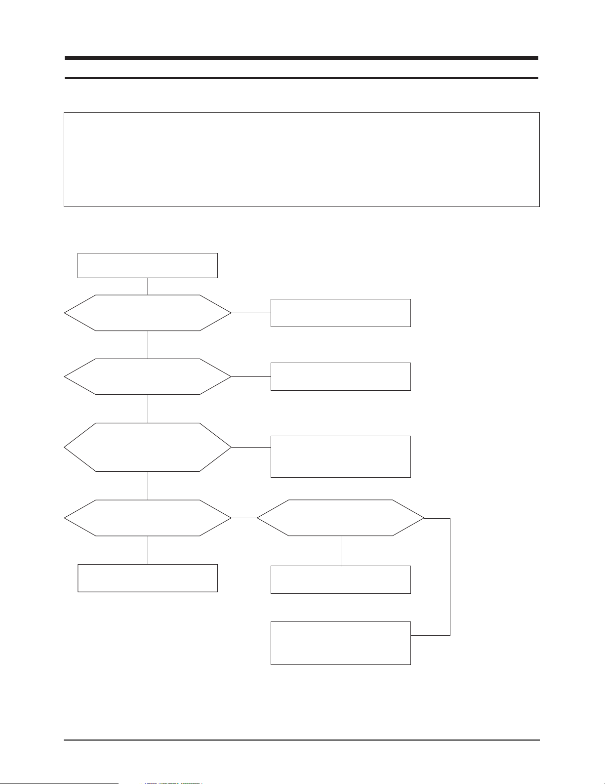
5-1-1 No Power Supply
Check and replace FH1,
D601, IC601 and ZD601.
Check the Voltage at
C605 plus polarity point.
Yes
IC601 Pin 1 waveform is correct?
Yes
The secondary
voltage of T601 is correct?
(Is it same as in the
schemetic diagram)
Yes
Check IC622 (KA78R12) Pin 2?
•
Is the voltage 12VDC?
•
Yes
Done
No
No
No
No
Check and replace FH601, D601.
Check and replace
IC601, ZD601, D603.
Check TR, IC and diode
related to every B+line.
Does 4VDC at Pin 5 of IC201?
No
Check MICOM. (IC201)
Yes
•
Check and replace IC622.
•
Check each IC connected to 12V.
LE17IS/LE19IS/LE19IT 5-1
Page 2
5 Troubleshooting
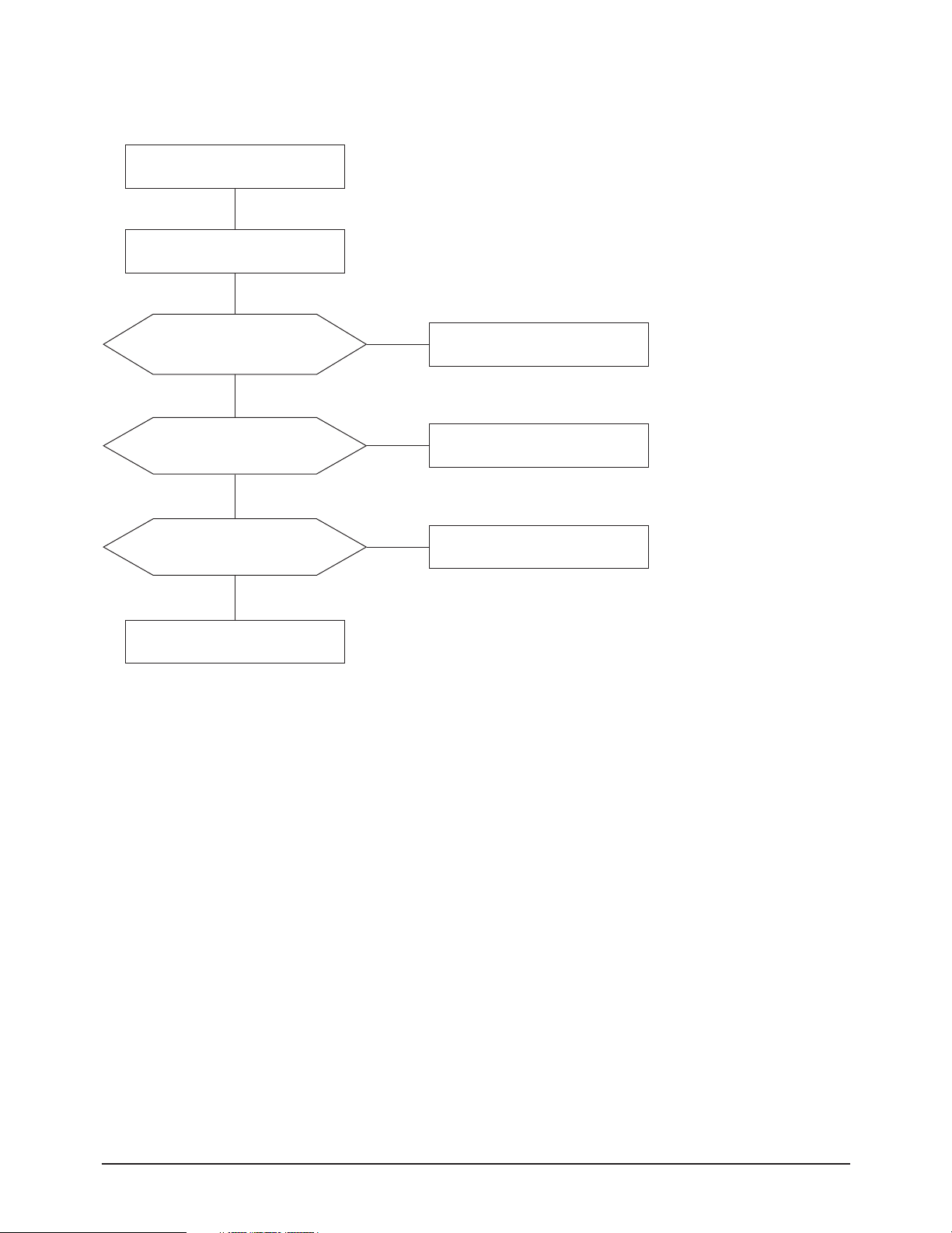
5-1-2 DPMS Failure
Check signal source
H/V sync. video signal.
Make No H/V sync.
( That is power off mode).
LED blinks?
Does +12V Line off?
(Check the IC622 output Pin 2)
Yes
Is +14V_V Line off?
(Check the Q625 Collector)
Yes
Does Q622 activate?
Yes
Done
No
No
No
Check IC201 Pin 5
or replace IC201.
Check Q625, D627.
Check IC201 Pin 6
or replace IC201.
5-2 LE17IS/LE19IS/LE19IT
Page 3

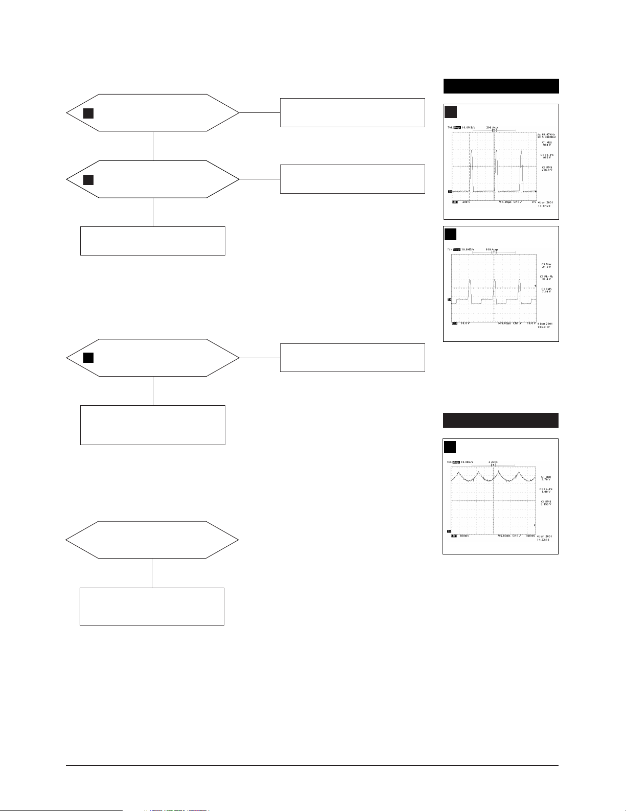
5-1-3 H_Deflection Failure
5 Troubleshooting
IC401 Pin 28 waveform is correct?
1
Yes
2
Q413 drain waveform is correct?
Yes
3
Q401 gate, drain
4
waveforms are correct?
Yes
Q490 base, collector
5
6
waveforms are correct?
WAVEFORMS
No
No
No
No
1. Check that DC 12V is displayed
at Pin 29 of IC401.
2. Replace IC401.
Check Q411, Q412.
Check Q403, Q404, IC401
Check +12VDCline.
Check and replace D406 and Q413.
Check DY connector connection.
IC401, #28
1
CH1 P-P = 10.96 V CH1 RMS = 6.180 V
Q401, Drain
4
Q413, Drain
2
Q490, Base
5
Q401, Gate
3
CH1 P-P = 11.6 V CH1 RMS = 6.944V
Q490, Collector
6
LE17IS/LE19IS/LE19IT 5-3
Page 4
5 Troubleshooting
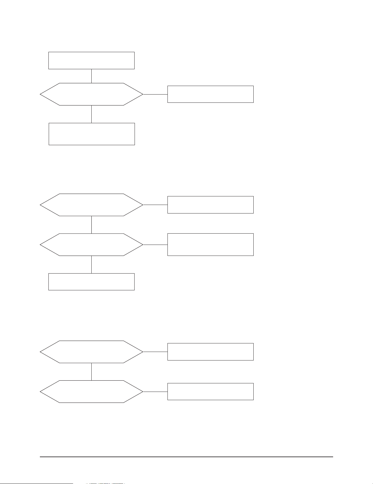
5-1-4 S Correction Failure
Check S1 ~ S4 signal.
Refer to the S-correction table page?
S1~S4 signals are correct at
each frequency block?
Yes
Check and replace
C451~C456, Q451~Q454, Q455~Q458.
5-1-5 H_Lin. Failure
IC201 Pin 23 voltage varies with
different H_Lin. DAC values?
Yes
Q459 Emitter voltage varies with
different H_Lin. DAC values?
Yes
No
No
No
Check and replace IC201.
Replace IC201.
Check +7 V line.
Check parts around Q459.
Check L441.
5-1-6 Invariable H_Size
IC401 Pin 28 pulse width
H_Size DAC values?
Yes
Q413 drain pulse width
output duty varies with different
H_Size DAC values?
No
Check and replace IC401, IC201.
No
Check parts around Q411, Q412.
5-4 LE17IS/LE19IS/LE19IT
Page 5
5-1-7 Abnormal H_Size
5 Troubleshooting
WAVEFORMS
Voltage waveforms at
6
Q490 Collector are correct?
Yes
7
T401 Pin 5 wareform is correct?
Yes
Check parts around
IC401 Pin 15 and 16.
5-1-8 Side Pin or Trap Failure
IC401 Pin 24 output exists?
8
The waveform is correct?
Yes
No
No
No
Repeat the troubleshooting
steps for H_deflection failure.
Replace T401.
Check and replace IC401.
Q490, Collector
6
T401, #5
7
Repeat troubleshooting for
5-1-7 abnormal H-Size.
5-1-9 Para. or Pin Balance Failure
IC401 Pin 24 output varies with
different DAC values?
No
Replace IC401.
WAVEFORMS
IC401, #24
8
LE17IS/LE19IS/LE19IT 5-5
Page 6

5 Troubleshooting
5-1-10 Tilt Failure
Check tilt connector.
IC201 Pin 24 output duty varies
with different DAC values?
Yes
Q323 collector voltage varies
with different DAC values?
Yes
Check and replace CRT.
5-1-11 V Deflection Failure
Is 14V at IC301 present at Pin 2?
Is -14V at IS301 present at Pin 4?
Yes
No
No
No
Check and replace IC201.
Check and replace Q323.
Refer to 5-1-1 No Power supply.
WAVEFORMS
IC401, #23
9
IC401 Pin 23 output exists?
9
The waveform is correct?
Yes
IC301 Pin 5 output exists?
10
The waveform is correct?
Yes
Check DY connector.
No
No
Check and replace IC401.
Check and replace
parts around IC301.
IC301, #5
10
5-6 LE17IS/LE19IS/LE19IT
Page 7

5-1-12 V Size or Pos. Variation Failure
5 Troubleshooting
IC401 Pin 23 output varies with
different DAC values?
Yes
Check and replace IC401 and IC301.
5-1-13 High Voltage Failure
Does Q590 gate driving pulse
11
exist? The waveform is correct?
Yes
Are there voltages
(350V, 30V, -210V, etc)
at secondary part of FBT?
No
No
No
Check parts around IC401.
Check bias voltage.
Check +12 V line.
Check and replace
Q502, Q503, R511, IC501.
Check and replace D531, D532, D533.
WAVEFORMS
Q590, Gate
11
Done
Yes
LE17IS/LE19IS/LE19IT 5-7
Page 8

5 Troubleshooting
5-1-14 ABL Failure
Input full white pattern to monitor.
IC102 Pin22 input exists and
varies with different patterns?
No
Check CN102.
T501 Pin 8 Voltage exists?
Yes
Check parts around IC501 Pin 8.
Yes
Check and replace IC102.
No
Check and replace T501.
5-1-15 Focus Failure
IC401 Pin 32 and C563
12
13
output are correct?
Yes
Some parts around
S-corrcetion circuit and
Q551 are correct?
Yes
Some parts around
T501 are correct?
Yes
Check the connection between FBT
Pin 13, CRT socket PCB.
No
No
No
Check and replace IC401.
Replace failed part.
Replace failed part.
WAVEFORMS
C563, 60V
12
CH1 P-P = 2.20 V CH1 RMS = 2.776 V
T501, #13
13
CH1 P-P = 580 V CH1 RMS = 278.2 V
5-8 LE17IS/LE19IS/LE19IT
Page 9

5-1-16 No Video
5 Troubleshooting
Check signal cable and connection.
IC102 Pins 5, 6 and 7
inputs are correct?
Yes
IC102 Pins 19, 20 and 21
outputs are correct?
Yes
IC106 Pins 8, 9 and 11
inputs are correct?
Yes
Are there waveforms at CRT
14
socket Pin red, green, blue?
Yes
No
No
No
No
Check parts around CN101.
Check VDCon IC102
and replace IC102.
Check +12 V line.
Check and replace IC106.
Check +80 V line.
Check and replace IC102 and
components around IC106.
WAVEFORMS
CRT Socket, Red, Green, Blue
14
G2 voltage is right?
Heater Voltage is correct?
Yes
Change CRT.
Done
No
Check D622, Q604 and G2 wire.
Check CN102 wire assy.
LE17IS/LE19IS/LE19IT 5-9
Page 10

5 Troubleshooting
5-1-17 Micom Failure
IC201 Pin 11 input is 5V?
Yes
15 16
IC201 Pin 13 and 14
inputs are correct?
Yes
IC201 Pin 18 input is high active?
Yes
All in/output values are correct?
Yes
Done
No
No
No
No
Check IC621.
Check X201, C203 and C204.
Check and replace IC201.
Replace IC201.
WAVEFORMS
3.42 V (IC201, #13)
15
CH1 P-P = 3.42 V CH1 RMS = 2.500V
3.16 V (IC201, #14)
16
CH1 P-P = 3.16 V CH1 RMS = 2.560 V
5-10 LE17IS/LE19IS/LE19IT
Page 11

5-1-18 OSD Failure
5 Troubleshooting
Check CN102 and connector assy.
17
IC102 Pin 1 and 24
18
waveforms are correct?
Yes
Does the voltage change on
IC201 Pins 41, 42 when you
push the control button?
Yes
Check IC201.
Done
No
No
Check and replace
H-BLK, VS-OUT
Check 5V Line.
Check CN203 and assy.
WAVEFORMS
IC102, #1
17
IC102, #24
18
LE17IS/LE19IS/LE19IT 5-11
Page 12

5 Troubleshooting
5-1-19 User Control Failure
Check connector assy.
IC201 Pin38 inputs are right
at each function?
Yes
Check and replace IC201.
Done
5-1-20 Degaussing Failure
Check degaussing connector.
RL601 operation is correct?
No
Check and replace function key.
Yes
Check D-Coil, TH601.
No
Q621 base input is correct?
No
IC201 Pin 19 output is correct?
Yes
Done
Yes
No
Check and replace Q621.
Check and replace IC201.
Check user function key.
5-12 LE17IS/LE19IS/LE19IT
Page 13

5-2 General Troubleshooting
5-2-1 No Picture
5 Troubleshooting
LED blinks?
No
G2 voltage is correct?
Yes
Heater voltage is correct?
Yes
19
R, G, B cathode is correct?
Yes
Check the CRT socket.
Replace the CRT.
Yes
No
No
No
Go to 5-2-2 shut down
troubleshooting guide.
Check D543, ZD541, ZD542
Q542 and G2 wire.
Also check around FBT circuits.
Check CN201 assy and D622, Q604.
Return to the no video (5-1-16)
troubleshooting guide.
WAVEFORMS
R, G, B, Video
19
5-2-2 Shut Down
LED is blinking rapidly
(Once per 300ms sec)?
No
LED is blinking once a second?
Yes
Check signal cable and signal source.
Yes
Check SDA (IC201 Pin 42) and SCL
(IC201 Pin 41) Replace IC241, IC201.
LE17IS/LE19IS/LE19IT 5-13
Page 14

5 Troubleshooting
5-2-3 Missing Color
Proper video levels exist at
CN101 Pin 1, 3 and 5.
Yes
Proper AC voltage exist
at all cathodes?
Yes
Proper DC voltage exist
at all cathodes?
Yes
G2 voltage is correct?
Yes
Change the CRT.
No
No
No
No
Check signal.
Refer to 5-1-16 no video.
Check IC106 Pin 8, 9 and 11.
Check FBT.
Done
5-14 LE17IS/LE19IS/LE19IT
Page 15

5-2-4 Visible Retrace
Check white balance adjustment.
5 Troubleshooting
G2 voltage is correct?
Yes
Blank pulse at R132 on video board?
Yes
Done
5-2-5 Unsynchronized Image
Compare input sync. of IC201
Pin 30 and 31 with output sync.
of IC201 28 and 29.
No
Check G2 control volume and FBT.
No
Check parts around CN201, Q541.
Are they all correct?
Yes
Are H_Out and V_Out
of IC401 Pin 23 and 26 correct?
Yes
Is H_FLYBACK of
IC102 Pin 24 correct?
Yes
Check clamp pulse of IC102
Pin 23 replace IC201.
Done
No
Check and replace IC201.
No
Check and replace IC401.
No
Check CN102 assy.
LE17IS/LE19IS/LE19IT 5-15
Page 16

5 Troubleshooting
5-2-6 Poor Focus
Age focus VR.
Improved focus?
No
Check focus leads from
FBT to CRT socket.
Check the CRT socket.
Dynamic focus circuit is correct?
Yes
Replace the CRT and verify focus.
Yes
No
Age monitor and
check for focus change.
Refer to 5-1-15 dynamic
focus failure.
5-2-7 Purity Failure
Degauss.
Purity is correct?
Degaussing circuit is correct?
Replace CRT and verify purity.
Yes
Done
No
No
Refer to 5-1-20 degaussing failure.
Yes
5-16 LE17IS/LE19IS/LE19IT
 Loading...