

Page 1

TRUE DIVERSITY
MICROPROCESSOR
WIRELESS SYSTEM
®
OWNERS MANUAL
Series
Series
WIRELESS SYSTEM
AND
Page 2

Produced by On The Right Wavelength for Samson Technologies Corp.
Copyright 1998, Samson Technologies Corp.
Printed May 1998
Samson Technologies Corp.
575 Underhill Blvd.
P.O. Box 9031
Syosset, NY 11791-9031
Phone: 1-800-3-SAMSON (1-800-372-6766)
Fax: 516-364-3888
Table of Contents
ENGLISH
Introduction 3
Guided Tour - VR3TD Receiver Front Panel 5
Guided Tour - VR3TD Receiver Rear Panel 6
Guided Tour - VR3 Receiver Front Panel 7
Guided Tour - VR3 Receiver Rear Panel 8
Guided Tour - VT3L / VT3 Transmitter 9
Guided Tour - VH3 Transmitter 11
Setting Up and Using Your VHF TD Series / VHF Series System 12
Appendix A: VT3L Multipin Wiring Guide and Chart 51
Appendix B: Carrying Case 52
Specifications 53
FRANCAIS
Introduction 15
Tour d'horizon - Façade avant du VR3TD 17
Tour d'horizon - Façade arrière du VR3TD 18
Tour d'horizon - Façade avant du VR3 19
Tour d'horizon - Façade arrière du VR3 20
Tour d'horizon - VT3L / VT3 21
Tour d'horizon - VH3 23
Réglage et utilisation du système VHF TD Series / VHF Series 24
DEUTSCHE
Einleitung 27
Übersicht: VR3TD Vorderseite 29
Übersicht: VR3TD Rückseite 30
Übersicht: VR3 Vorderseite 31
Übersicht: VR3 Rückseite 32
Übersicht: VT3L / VT3 33
Übersicht: VH3 35
Aufbau und Betrieb des VHF TD Series / VHF Series 36
ESPANOL
Introducción 39
Recorrido guiado - Panel frontal del VR3TD 41
Recorrido guiado - Panel trasero del VR3TD 42
Recorrido guiado - Panel frontal del VR3 43
Recorrido guiado - Panel trasero del VR3 44
Recorrido guiado - VT3L / VT3 45
Recorrido guiado - VH3 47
Ajuste y utilización de su sistema VHF TD Series / VHF Series 48
2
Page 3

Introduction
Congratulations on purchasing the Samson VHF TD Series or VHF Series Wireless
System! Although this product is designed for easy operation, we suggest you first take
some time to go through these pages so you can fully understand how we’ve implemented
a number of unique features.
Every wireless system consists of at least two components—a transmitter and a receiver,
both of which must be tuned to the same channel (that is, the same radio frequency) in
order to operate correctly.* The Samson VHF TD Series or VHF Series system you have
purchased operates in the 173.8 - 213.2 MHz frequency range and contains either a
VR3TD or VR3 receiver as well as one of the following transmitters: a VT3L belt-pack
transmitter (for lavalier microphone or headset applications); a VT3 belt-pack transmitter
(for instrument applications); or a VH3 hand-held microphone transmitter. For
convenience and security, the VHF TD Series and VHF Series system is packaged in a
custom impact-resistant polypropylene plastic carrying case that provides room for all
components (see Appendix B on page 50 for more information).
The VT3L beltpack transmitter provides a Switchcraft P3 mini-XLR jack for connection to a
variety of popular headsets and lavalier microphones, including:
Samson QV headset
Samson QE headset**
Audio-Technica ATM-75 headset
Audio-Technica
MT-350 lavalier
Audio-Technica Pro-8HE headset**
Audio-Technica 831H-7 lavalier
Countryman IsoMax headset
Crown
CM-311(E) headset
Foster ECM-40 lavalier
Sennheiser MKE-2 lavalier
Sony ECM-44 lavalier
Sony ECM-55 lavalier
Sony
ECM-77 lavalier
The VH3 hand-held microphone transmitter is available in a selection of popular mic
capsules, including:
Electro Voice
ND 757A N/DYM dynamic
Electro Voice ND 857 N/DYM dynamic
Electro Voice BK-1 condenser
Samson
Q MIC dynamic
Sennheiser MKE-4032 condenser
Shure SM58 dynamic
Shure SM85 condenser
Shure
SM87 condenser
* Your receiver and transmitter have been factory preset to utilize the same channel.
** Optimized for aerobics workouts, this waterproof headset is recommended for usage in
high-humidity environments such as physical fitness centers.
3
ENGLISH
Page 4

Introduction
The VR3 receiver provided with the VHF Series wireless system utilizes non-diversity
technology, incorporating a single antenna for ease of use and minimal cost. The VR3TD
receiver provided with the VHF TD Series system utilizes a patented technological
breakthrough called “Microprocessor True Diversity,” whereby a single chassis houses
two antennas (called “Antenna A” and “Antenna B”) and a receiver circuit. A built-in
computer chip continuously scans RF signals from the two antennas and determines
which one has the clearest and strongest reception, automatically (and silently) switching
that signal to the receiver. This allows you to maintain the wireless communication link
over a much broader area range than would be allowed by a receiver utilizing a single
antenna and also virtually eliminates multipath dropouts, interference and phase
cancellation problems. In addition, special sample-and-hold linking circuitry ensures that
correct phase correlation is maintained at all times, with no noise or pops during antenna
switching. The result is performance which exceeds that of conventional antenna true
diversity systems and the highest quality audio fidelity available in
any wireless system.
Finally, the provision of Signetics® noise reduction produces crystal-clear sound with
minimized background noise and hiss.
In this manual, you’ll find a more detailed description of the features of your VHF TD
Series or VHF Series system, as well as a guided tour through all components, step-bystep instructions for setting up and using your system and full specifications. If your
VHF TD Series or VHF Series system was purchased in the United States, you’ll also find
a warranty card enclosed—don’t forget to fill it out and mail it! This will enable you to
receive online technical support and will allow us to send you updated information about
other Samson products in the future. If your VHF TD Series or VHF Series system was
purchased outside of the United States, contact your local distributor for warranty details.
SPECIAL NOTE for U.S. purchasers: Should your VHF TD Series or VHF Series system
ever require servicing, a
Return Authorization number (RA) is necessary. Without this
number, the unit will not be accepted. Please call Samson at 1-800-372-6766 for a
Return Authorization number prior to shipping your unit. Please retain the original packing
materials and, if possible, return the unit in its original carton and packing materials.
If your VHF TD Series or VHF Series system was purchased outside of the United States,
contact your local distributor for servicing information.
4
ENGLISH
Page 5

5
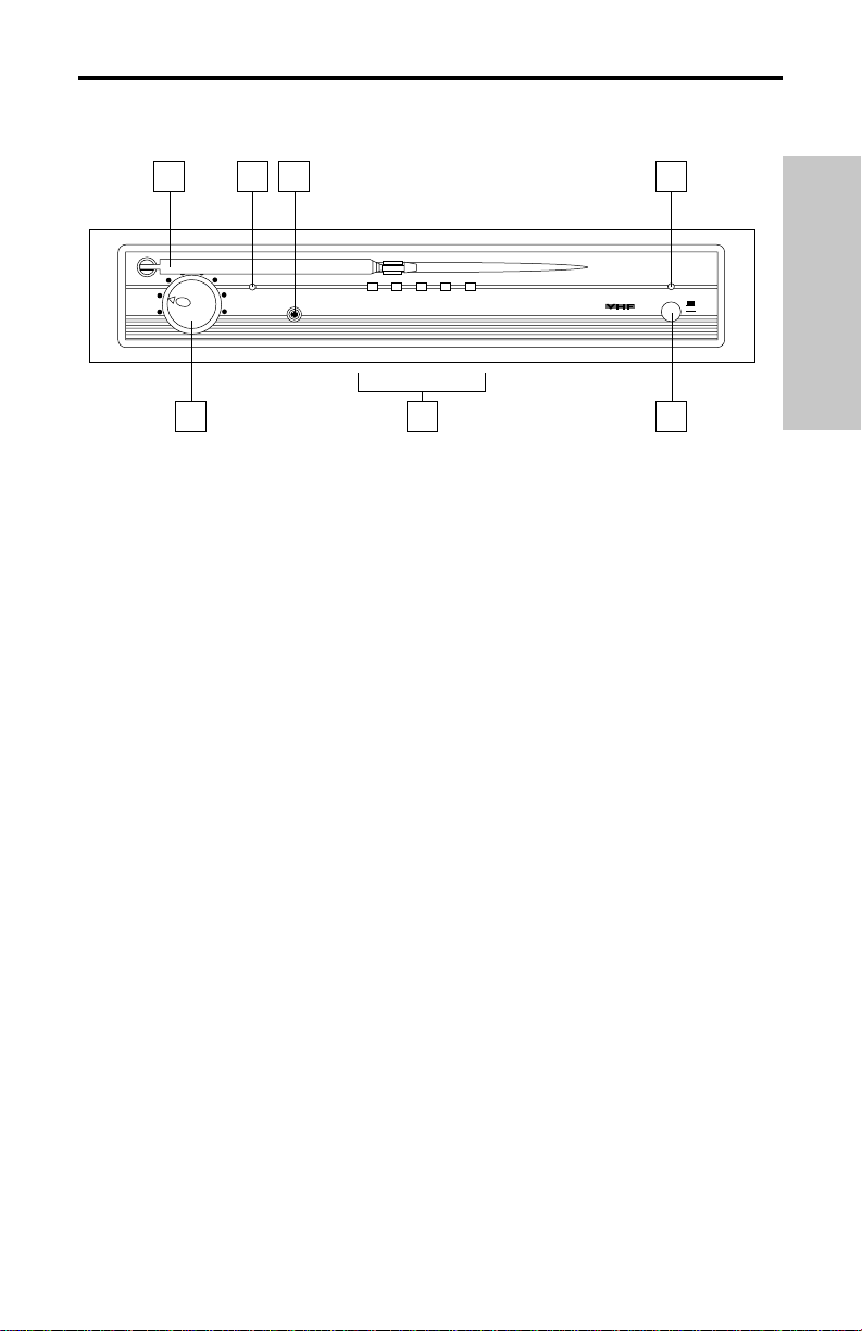
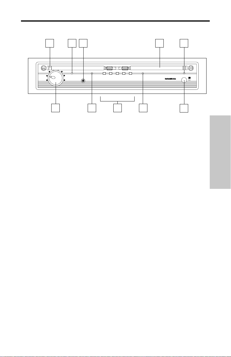
Guided Tour - VR3TD Front Panel
1: Antennas (A and B) - The antenna mountings allow full rotation for optimum
placement. In normal operation, both Antenna A (the antenna on the left) and Antenna B
(the antenna on the right) should be placed in a vertical position. Both antennas can be
folded inward for convenience when transporting the VR3TD. See the “Setting Up and
Using Your VHF TD Series / VHF Series System” section on page 10 in this manual for
more information about antenna positioning.
2: Volume control - This knob sets the level of the audio signal being output through both
the balanced and unbalanced output jacks on the rear panel. Reference level is obtained
when the knob is turned fully clockwise.
3: “TX ON” LED - Lights when carrier signal of sufficient strength is being received by the
VR3TD.
4: SQL (Squelch) control - This control determines the maximum range of the VR3TD
before audio signal dropout. Although it can be adjusted using the supplied plastic
screwdriver, it should normally be left at its factory setting. See the “Setting Up and Using
Your VHF TD Series / VHF Series System” section on page 10 in this manual for more
information.
5: A/B LEDs - When signal is being received, one of these will be lit yellow, showing you
whether the (left) “A” or (right) “B” receiver is currently being used. The VR3TD constantly
scans its two antennas and automatically selects whichever is receiving the strongest,
clearest signal. This
Microprocessor True Diversity switching is completely inaudible, but it
effectively increases overall range while virtually eliminating potential interference and
phase cancellation problems.
6: AF Level meter - This “ladder” display (similar to the VU bar meter used on audio
devices) indicates the strength of the incoming audio signal. When the “100%” segment is
lit, the incoming signal is optimized at unity gain; when the “125%” segment is lit, the signal
is overloading. When only the left-most “10%” segment is lit, the incoming signal is at just
10% of optimum strength. If no segments are lit, little or no signal is being received.
See the “Setting Up and Using Your VHF TD Series / VHF Series System” section on page
10 in this manual for more information.
7: Power LED - This lights green whenever the VR3TD is turned on.
8: Power switch - Use this to turn the VR3TD power on and off. When it is on, the Power
LED (see #7 above) is lit.
ENGLISH
1
VOLUME
3 4
SQL. MIN.
ANT. A
MAX.
5
10% 25% 75% 100%
VR3TD VHF TRUE DIVERSITY RECEIVER
125%
6
ANT. B
TX
2
SAMSON
5
1 7
Series
POWER
OFF
ON
8
Page 6
6
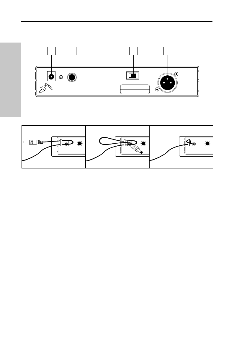
Guided Tour - VR3TD Rear Panel
1: DC input - Connect the supplied 12 volt 250 mA power adapter here, using the strain
relief as shown in the illustration below. WARNING: The substitution of any other kind of
power adapter can cause severe damage to the VR3TD and will void your warranty.
2: Unbalanced output* - Use this unbalanced high impedance (5K Ohm) 1/4" jack when
connecting the VR3TD to consumer (-10) audio equipment. Wiring is as follows: tip hot,
sleeve ground.
3: Audio Output Level switch - Sets the audio output level attenuation of the balanced
output (see #4 below) to -20 dBm (line level) or -40 dBm (mic level). See the “Setting Up
and Using Your VHF TD Series / VHF Series System” section on page 10 in this manual
for more information.
4: Balanced output* - Use this electronically balanced low impedance (600 Ohm) XLR
jack when connecting the VR3TD to professional (+4) audio equipment. Pin wiring is as
follows: Pin 1 ground (shield), Pin 2 high (hot), and Pin 3 low (cold).
* If required, both the unbalanced and balanced outputs can be used simultaneously.
Using the strain relief: Gather up a loop of wire and pass it through the strain relief,
then pass the adapter plug through the loop in order to create a knot.
ENGLISH
1
DC INPUT
AC CABLE LOCK
CABLE LOCK LOOP THRU AND TIE
+
CAUTION
USE SAMSON
AC ADAPTER
ONLY
2
UNBALANCED OUTPUT
-
-10 dB 5KΩ
S. No.
CH :
Diversity Receiver
F:
3
BALANCED SWITCH
LINE
MIC
POWER RATING
DC 12V, 1.9W(160mA)
LINE:
-20dBm600Ω
MIC:
-40dBm600Ω
4
BALANCED OUTPUT
XLR:
①GND
②HOT
③COLD
-
Page 7
Guided Tour - VR3 Front Panel
1: Antenna - The antenna mounting allows full rotation for optimum placement. In normal
operation, the antenna should be placed in a vertical position. It also can be folded inward
for convenience when transporting the VR3. See the “Setting Up and Using Your VHF TD
Series / VHF Series System” section on page 10 in this manual for more information about
antenna positioning.
2: Volume control - This knob sets the level of the audio signal being output through both
the balanced and unbalanced output jacks on the rear panel. Reference level is obtained
when the knob is turned fully clockwise.
3: “TX ON” LED - Lights when carrier signal of sufficient strength is being received by the
VR3.
4: SQL (Squelch) control - This control determines the maximum range of the VR3
before audio signal dropout. Although it can be adjusted using the supplied plastic
screwdriver, it should normally be left at its factory setting. See the “Setting Up and Using
Your VHF TD Series / VHF Series System” section on page 10 in this manual for more
information.
5: AF Level meter - This “ladder” display (similar to the VU bar meter used on audio
devices) indicates the strength of the incoming audio signal. When the “100%” segment is
lit, the incoming signal is optimized at unity gain; when the “125%” segment is lit, the signal
is overloading. When only the left-most “10%” segment is lit, the incoming signal is at just
10% of optimum strength. If no segments are lit, little or no signal is being received.
See the “Setting Up and Using Your VHF TD Series / VHF Series System” section on page
10 in this manual for more information.
6: Power LED - This lights green whenever the VR3 is turned on.
7: Power switch - Use this to turn the VR3 power on and off. When it is on, the Power
LED (see #6 above) is lit.
7
ENGLISH
VOLUME
1
3 4
TX
SQL. MIN.
MAX.
10% 25% 75% 100%
VR3 VHF FM RECEIVER
2
125%
SAMSON
5
Series
POWER
6
OFF
ON
7
Page 8

Guided Tour - VR3 Rear Panel
1: DC input - Connect the supplied 12 volt 250 mA power adapter here, using the strain
relief as shown in the illustration below. WARNING: The substitution of any other kind of
power adapter can cause severe damage to the VR3 and will void your warranty.
2: Unbalanced output* - Use this unbalanced high impedance (5K Ohm) 1/4" jack when
connecting the VR3 to consumer (-10) audio equipment. Wiring is as follows: tip hot,
sleeve ground.
3: Audio Output Level switch - Sets the audio output level attenuation of the balanced
output (see #4 below) to -20 dBm (line level) or -40 dBm (mic level). See the“Setting Up
and Using Your VHF TD Series / VHF Series System” section on page 10 in this manual
for more information.
4: Balanced output* - Use this electronically balanced low impedance (600 Ohm) XLR
jack when connecting the VR3 to professional (+4) audio equipment. Pin wiring is as
follows: Pin 1 ground (shield), Pin 2 high (hot), and Pin 3 low (cold).
* If required, both the unbalanced and balanced outputs can be used simultaneously.
8
ENGLISH
Using the strain relief: Gather up a loop of wire and pass it through the strain relief,
then pass the adapter plug through the loop in order to create a knot.
1
DC INPUT
AC CABLE LOCK
CABLE LOCK LOOP THRU AND TIE
+
CAUTION
USE SAMSON
AC ADAPTER
ONLY
2
UNBALANCED OUTPUT
-
-10 dB 5KΩ
S. No.
CH :
Non-Diversity Receiver
F:
3
BALANCED SWITCH
LINE
MIC
POWER RATING
DC 12V, 1.9W(160mA)
LINE:
-20dBm600Ω
MIC:
-40dBm600Ω
4
BALANCED OUTPUT
XLR:
①GND
②HOT
③COLD
-
Page 9
9
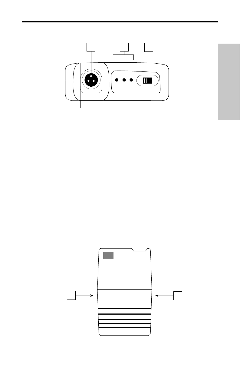
Guided Tour - VT3L / VT3
1: Input connector - The input device is connected here. The VT3L is supplied with
either a lavalier or headset microphone (connected via a Switchcraft mini-XLR jack), while
the VT3 is supplied with a permanently connected cable that terminates at a 1/4" plug.
A wiring chart showing the connections to popular lavalier and headset microphones can
be found on page 49 of this manual.
2: Battery level meter - This set of three multicolor LEDs indicates relative battery
power, indicating whether the installed battery is at low (red), mid (yellow) or high (green)
strength. One or more of these will light whenever the VT3L or VT3 is powered on (see
#5 on the next page). When all three are lit, the battery is at maximum strength. When
only the red “low” indicator lights, RF performance is degraded and the battery needs to
be replaced.
3: Audio on-off switch - When set to the “on” position, audio signal is transmitted.
When set to the “off” position, the audio signal is muted. Because the carrier signal
remains during muting, no “pop” or “thud” will be heard. Note that turning this off does
not
turn off the transmitter power—it is simply a way to temporarily mute the transmission of
audio signal. If you don’t plan on using the transmitter for extended periods, turn off the
transmitter power by using the power on-off switch (see #5 on the next page).
4: Battery door release - Press gently inwards on these two indents in order to open the
battery door of the VT3L or VT3 and access the Power on-off switch (see #5 on the next
page) and Gain control (see #6 on the next page).
ENGLISH
AUDIO
3
ON
▲
1
2
LOW MID HIGH
BATTERY
SAMSON
VT3
4
VHF BELTPACK TRANSMITTER
INPUT
SAMSON
4
Page 10
10
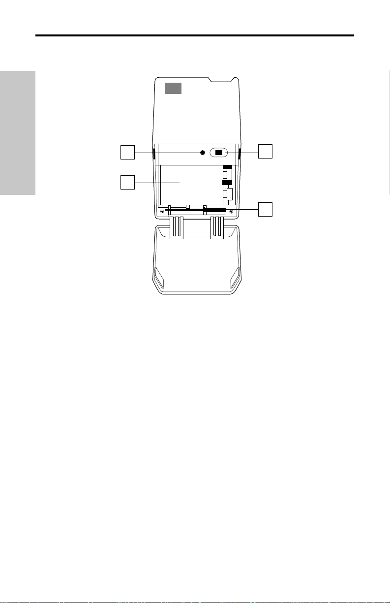
Guided Tour - VT3L / VT3
5: Power on-off switch* - Use this to turn the VT3L / VT3 on or off (to conserve battery
power, be sure to leave it off when not in use).
6: Gain control (trimpot) - This input sensitivity control has been factory preset to provide
optimum level for the particular lavalier or headset model being used (in the case of the
VT3, it is preset for optimum instrument level) and so we recommend that this not be
adjusted manually. If necessary, however, you can use the supplied plastic screwdriver
(see #8 below) to raise or lower the VT3L / VT3 Gain control. See the “Setting Up and
Using Your VHF TD Series / VHF Series System” section on page 10 in this manual for
more information.
7: Battery holder - Insert a standard 9-volt alkaline battery here, being sure to observe
the plus and minus polarity markings shown. We recommend the Duracell MN 1604 type
battery. Although rechargeable Ni-Cad batteries can be used, they do not supply adequate
current for more than four hours.
WARNING: Do not insert the battery backwards; doing
so can cause severe damage to the VT3L / VT3 and will void your warranty.
8: Plastic screwdriver - Specially designed for use in adjusting the VT3L / VT3 Gain
control (see #7 above) and/or receiver Squelch control (see #4 on pages 3 and 5). See the
“Setting Up and Using Your VHF TD Series / VHF Series System” section on page 10 in
this manual for more information.
* Be sure to mute the audio signal at your external mixer or amplifier before turning
transmitter power on or off, or an audible pop may result.
ENGLISH
VT3
6
INPUT
SAMSON
GAIN
ON
POWER
▲
5
7
SAMSON
8
Page 11
11
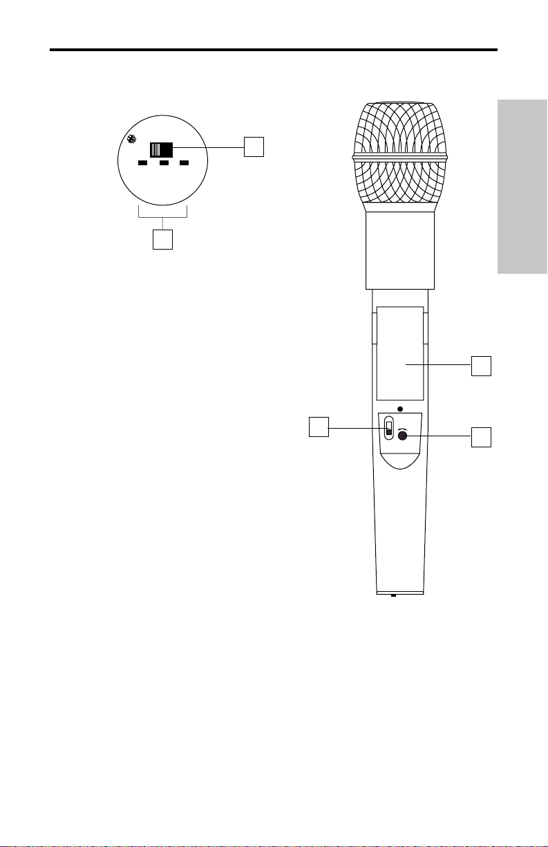
Guided Tour - VH3
1: Audio on-off switch - When set to the “on”
position, audio signal is transmitted. When set to
the “off” position, the audio signal is muted.
Because the carrier signal remains during muting,
no “pop” or “thud” will be heard. Note that turning
this off does
not turn off the transmitter power—it is
simply a way to temporarily mute the transmission
of audio signal. If you don’t plan on using the VH3
for extended periods, turn off its power by using
the power on-off switch (see #3 below).
2: Battery level meter - This set of three
multicolor LEDs indicates relative battery power,
indicating whether the installed battery is at low
(red), mid (yellow) or high (green) strength.
One or more of these will light whenever the VH3
is powered on (see #3 below). When all three are
lit, the battery is at maximum strength. When only
the red “low” indicator lights, RF performance is
degraded and the battery needs to be replaced.
3: Power on-off switch* - Use this to turn the
VH3 on or off (to conserve battery power, be sure
to leave it off when not in use).
4: Gain control (trimpot) - This input sensitivity
control has been factory preset to provide optimum
level for the particular microphone capsule provided with your VHF TD Series or
VHF Series system and so we recommend that this not be adjusted manually. If necessary, however, you can use the supplied plastic screwdriver to raise or lower the input
level. See the “Setting Up and Using Your VHF TD Series / VHF Series System” section
on page 10 in this manual for more information.
5: Battery holder - Insert a standard 9-volt alkaline battery here, being sure to observe
the plus and minus polarity markings shown. We recommend the Duracell MN 1604 type
battery. Although rechargeable Ni-Cad batteries can be used, they do not supply
adequate current for more than four hours.
WARNING: Do not insert the battery
backwards; doing so can cause severe damage to the VH3 and will void your warranty.
* Be sure to mute the audio signal at your external mixer or amplifier before turning
transmitter power on or off, or an audible pop may result.
ENGLISH
x
x
x
x
x
x
x
x
T
AUDIO
Ch2
2
C
A
N
A
D
A
:
X
X
X
X
X
X
X
X
X
1
SAMSON
ON
MIN
3
MAX
OFF
POWER
LEVEL
Z
B
3
OFF ON
H
V
R
C
C
LOW MID HIGH
D
BATTERY LEVEL
I
C
C
F
5
4
Page 12

12
Setting Up and Using Your VHF TD Series/ VHF Series System
The basic procedure for setting up and using your VHF TD Series or VHF Series Wireless
System takes only a few minutes:
1. For the VHF TD Series / VHF Series system to work correctly, both the receiver and
transmitter must be set to the same channel. Remove all packing materials (save them
in case of need for future service) and check to make sure that the supplied receiver and
transmitter are set to the same channel. If these channels do not match, contact your
distributor or, if purchased in the United States, Samson Technical Support at
1-800-372-6766.
2. Physically place the receiver where it will be used (the general rule of thumb is to
maintain “line of sight” between the receiver and transmitter so that the person using or
wearing the transmitter can see the receiver). An optional rack-mount kit (available from
your Samson dealer) allows the VR3TD or VR3 to be mounted in a standard 19" rack if
desired. Extend the antenna or antennas and place them in a vertical position.
3. Make sure the Power on-off switch in your VT3L / VT3 belt-pack or VH3 handheld
transmitter is set to “Off.”
4a. If your system contains a VT3L or VT3 belt-pack transmitter, press gently inwards on
both battery cover release indents to open the battery door. Note that this door is hinged
and not intended to be removed from the transmitter case. Please use care when opening
this door as undue force will destroy the hinge.
4b. If your system contains a VH3 handheld transmitter, unscrew the bottom section of
the microphone by turning it counterclockwise and then slide it off.
5. Place a fresh 9-volt alkaline battery in the transmitter battery holder, taking care to
observe the polarity markings. If you are using a VT3L or VT3 belt-pack transmitter, gently replace the battery door by swinging it up and pressing until it clicks. If you are using a
SH4 handheld transmitter, replace the bottom section of the microphone by sliding it on
and then screwing it back on. Whichever transmitter you are using, leave it off for the
moment.
6. Make the physical cable connection between the VR3TD or VR3 output jack and the
line or mic level audio input of your amplifier or mixer. If you are using the balanced XLR
jack (preferable, since it will deliver an electromagnetically cleaner signal), be sure to set
the receiver rear panel Audio Output Level switch correctly. If required, both the balanced
and unbalanced outputs can be used simultaneously. Leave your amplifier (and/or mixer)
off at this time.
7. Turn the Volume knob on the VR3TD or VR3 completely counterclockwise. Using the
strain relief, connect the supplied AC adapter to the DC Input on the rear panel of the
VR3TD or VR3, then plug the adapter into any standard AC outlet. Press the front panel
Power switch to turn on the VR3TD or VR3; the green “Power” LED will light up, but all
other front panel LEDs will remain unlit.
8. Turn on the power to the VT3L, VT3 or VH3 transmitter (using its Power on-off switch);
all three Battery strength LEDs will light if the battery is sufficiently strong. At this point,
the “TX” LED on the front panel of the receiver will light. If you are using an VR3TD
receiver, either the “A” or “B” yellow LED on the front panel will also light, depending upon
which antenna is receiving the stronger signal.
ENGLISH
Page 13

13
Setting Up and Using Your
VHF TD Series/ VHF Series System
9. Now it’s time to set the audio levels. Turn on your connected amplifier and/or mixer but
keep its volume all the way down. Next, make sure that your transmitter is unmuted by
setting its Audio switch to “On.” Then set the Volume knob on the VR3TD or VR3 fully
counterclockwise. If you are using the VH3 transmitter or if you are using the VT3L
transmitter with a connected lavalier microphone or headset, speak or sing into the mic at a
normal performance level while observing the VR3TD or VR3 front panel AF Level meter.
If you are using the VT3 transmitter with a connected instrument, play the instrument at
normal performance level while observing the VR3TD or VR3 front panel AF Level meter.
If the “100%” (unity gain) segment is lighting steadily, with just occasional higher
excursions, the audio level is correctly set. If not, use the supplied plastic screwdriver to
slowly adjust the VH3, VT3L, or VT3 Gain control (trimpot) until the VR3TD or VR3 AF
Level meter “100%” (unity gain) segment lights steadily (with occasional higher excursions). Then slowly raise the VR3TD or VR3 Volume knob to the 2 o’clock position (unity
gain) and, finally, set the volume of your amplifier/mixer until the desired level is reached.
If you are using a VT3L beltpack transmitter equipped
with a lavalier microphone, note that correct lavalier
placement is critical to sound quality. We
recommend that you place it as shown in the
illustration on the right—as close to your mouth as
possible but off to one side (to minimize nasality)
and unobstructed by clothing. Bear in mind also that
omni microphones (mics which pick up signal from all
directions) are more prone to feedback problems than
unidirectional (cardioid or supercardioid) ones; in
general, you can avoid feedback by taking care not to
use any microphone directly in front of a PA speaker
(if this is unavoidable, try using an equalizer to
attenuate those high- or mid-range frequencies which
are causing the feedback “squealing”).
10. If you hear distortion at the desired volume level (or if the “125%” segment LED in the
AF Level meter is lighting frequently), first check that the VR3TD or VR3 rear panel Audio
Output Level switch is set correctly. Next, make sure that the gain structure of your audio
system is correctly set (consult the owners manual of your mixer and/or amplifier for
details). If you still hear distortion, do the following:
• If you are using a VH3 handheld transmitter or an VT3L transmitter with connected
lavalier microphone or headset, its Gain control has been factory preset to provide
optimum level for the particular microphone model being used and so no adjustment
should be necessary. Any distortion present should therefore simply be a matter of
the microphone being too close to the mouth; try moving it further away. If this does
not solve the problem, use the supplied plastic screwdriver to turn the Gain control
(trimpot) on the VH3 or VT3L slowly counterclockwise until the distortion disappears.
• If you are using a VT3 transmitter with an instrument such as electric guitar or bass,
lower the output level of the instrument until the distortion disappears. Alternatively,
you can use the supplied plastic screwdriver to turn the Gain control (trimpot) on the
VT3 slowly counterclockwise until the distortion disappears.
Note that, following this setup procedure, you can always lower the Volume knob of the
VR3TD or VR3 in order to further attenuate the output signal if necessary.
ENGLISH
VT3L
SAMSON
VHF BELTPACK TRANSMITTER
INPUT
Page 14

14
Setting Up and Using Your
VHF TD Series/ VHF Series System
11. Conversely, if you hear a weak, noisy signal at the desired volume level (and with the
Volume control of the receiver turned fully clockwise), again make sure that the VR3TD or
VR3 rear panel Audio Output Level switch is set correctly and that the gain structure of
your audio system is correctly set. If it is and the signal coming from the VR3TD or VR3 is
still weak and/or noisy, do the following:
• If you are using a VH3 transmitter or an VT3L transmitter with connected lavalier
microphone or headset, its Gain control has been factory preset to provide optimum
level for the particular microphone model being used and so no adjustment should be
necessary. Any weakness of signal should therefore simply be a matter of the
microphone being too far from the mouth; try moving it closer. If this does not solve
the problem, use the supplied plastic screwdriver to turn the Gain control (trimpot) on
the VH3 or VT3L slowly clockwise until the signal reaches an acceptable level.
• If you are using a VT3 transmitter with an instrument such as electric guitar or bass,
raise the output level of the instrument until a good signal is achieved. Alternatively,
you can use the supplied plastic screwdriver to turn the Gain control (trimpot) on the
VT3 slowly clockwise until the signal reaches an acceptable level.
12. Temporarily turn down the level of your mixer/amplifier system and turn off the power
to your transmitter, leaving the VR3TD or VR3 on. Then restore the previously set level of
your mixer/amplifier. With the transmitter off, the receiver output should be totally silent—if
it is, skip ahead to the next step. If it isn’t (that is, if you hear some noise), you may need
to adjust the receiver’s front panel Squelch control. When the Squelch control is at its
minimum setting, the VHF TD Series / VHF Series system always provides maximum
range without dropout; however, depending upon the particular environment your system is
used in, you may need to reduce that range somewhat in order to eliminate band noise or
interference when the transmitter is turned off. To do so, use the provided screwdriver to
rotate the Squelch control completely counterclockwise (to the “Min” position), then slowly
turn it clockwise until the noise disappears. If no noise is present at any position, leave it at
its fully counterclockwise “Min” position (so as to have the greatest overall range available).
13. When first setting up the VHF TD Series or VHF Series System in a new environment,
it’s always a good idea to do a walkaround in order to make sure that coverage is provided
for your entire performance area. Accordingly, turn down the level of your audio system
and turn on both the transmitter and receiver. Then, with the transmitter unmuted, restore
the level of your audio system and while speaking, singing, or playing your instrument, walk
through the entire area that will need to be covered. As you do so, the “TX” LED on the
front panel of the VR3TD or VR3 should always remain lit. If you are using a VHF TD
Series system, one of the yellow “A” and “B” LEDs on the VR3TD receiver should always
be lit, though occasionally switching to show you which antenna is receiving the stronger
signal. Always try to minimize the distance between transmitter and receiver as much as
possible so that the strongest possible signal is received from all planned transmission
points. In fixed installations such as A/V or corporate conference rooms or for extended
range applications (where the transmitter and receiver are more than 150 feet apart), it
may be desirable to angle the receiver antenna or antennas differently from their vertical
position or to install the receiver in the same room as the transmitters (and, if necessary,
to extend the wiring to remote audio equipment).
If you have followed all the steps above and are experiencing difficulties, contact your
local distributor or, if purchased in the United States, call Samson Technical Support
(1-800-372-6766) between 9 AM and 5 PM EST.
ENGLISH
Page 15

Introduction
Merci d'avoir fait confiance au système sans fil VHF Samson VHF TD Series ou VHF
Series ! Ces deux produits sont très simples d'emploi, mais nous vous conseillons tout de
même de lire ces quelques pages pour tirer parti de tout leur potentiel.
Un système sans fil est composé d'au moins deux éléments (émetteur et récepteur) qui
doivent être réglés sur le même canal (sur la même haute fréquence) pour fonctionner
correctement.* Le système Samson VHF TD Series ou VHF Series que vous avez acquis
fonctionne sur une plage de fréquence de 173,8 à 213,2 MHz et est équipé d'un récepteur
VR3TD ou VR3 ainsi que l'un des émetteurs suivants : émetteur de ceinture VT3L (pour les
microphones cravate et serre-tête), émetteur de ceinture VT3 (pour instruments) ou
microphone main VH3. Pour davantage de sécurité et pour faciliter leur transport, les
systèmes VHF TD Series et VHF Series sont livrés dans un boîtier antichoc en plastique
polypropylene (voir Annexe B, page 50 pour de plus amples détails).
L'émetteur de ceinture VT3L dispose d'un connecteur mini-XLR Switchcraft P3 qui peut
accueillir la plupart des microphones serre-tête et cravate, dont les modèles suivants :
Samson QV (serre-tête)
Samson QE (serre-tête)**
Audio-Technica ATM-75 (serre-tête)
Audio-Technica MT-350 (cravate)
Audio-Technica Pro-8HE (serre-tête)**
Audio-Technica
831H-7 (cravate)
Countryman IsoMax (serre-tête)
Crown CM-311(E) (serre-tête)
Foster ECM-40 (cravate)
Sennheiser
MKE-2 (cravate)
Sony ECM-44 (cravate)
Sony ECM-55 (cravate)
Sony ECM-77 (cravate)
Le microphone main VH3 est disponible avec la majorité des capsules, dont les modèles
suivants :
Electro Voice
ND 757A N/DYM dynamique
Electro Voice
ND 857 N/DYM dynamique
Electro Voice BK-1 à condensateur
Samson Q MIC dynamique
Sennheiser MKE-4032 à condensateur
Shure
SM58 dynamique
Shure SM85 à condensateur
Shure SM87 à condensateur
* L'émetteur et le récepteur ont été réglés d'usine sur le même canal.
** Optimisé pour les applications sportives, l'utilisation de ce micro serre-tête étanche est
recommandée en environnement très humide comme les salles de sport et les centres de
remise en forme.
15
FRANCAIS
Page 16

Introduction
Le récepteur VR3 du système sans fil VHF Series fait appel à la technologie non-diversity,
incorpore une seule antenne pour une plus grande simplicité d'emploi et des coûts plus
faibles. Le récepteur VR3TD du système VHF TD Series fait appel à une technologie
brevetée du nom de True Diversity à microprocesseur, dans laquelle deux antennes
(appelées "Antenne A" et "Antenne B") et un circuit de réception sont placés dans seul
châssis. Le processeur électronique intégré examine en permanence les deux antennes
pour détecter la présence de signaux HF afin de déterminer celle qui dispose de la
meilleure réception et commute automatiquement (et en silence) le signal vers le
récepteur. Ce procédé permet d'obtenir une portée de la liaison sans fil bien plus grande
que ne pourrait l'offrir un récepteur utilisant une seule antenne et supprime également les
problèmes de perte de signal, d'interférences et de déphasage. En outre, le circuit de
liaison sample-and-hold assure en permanence une bonne corrélation de phase sans
bruit et sans pop lors de la commutation de l'antenne. Vous obtenez des performances
bien supérieures aux systèmes d'antenne true diversity et une qualité sonore de haute
fidélité quel que soit le système sans fil utilisé. Enfin, le réducteur de bruit Signetics
permet d'offrir un son très clair avec un bruit de fond et un sifflement réduits au minimum.
Ce manuel vous donne une description détaillée des caractéristiques et fonctions des
systèmes VHF TD Series et VHF Series, un petit tour d'horizon des éléments qui les
composent, les consignes de configuration et d'utilisation de votre système et leurs
caractéristiques techniques. Si vous avez acquis votre système VHF TD Series ou
VHF Series aux Etats-Unis, remplissez la carte de garantie fournie et retournez-la nous.
Vous pourrez ainsi bénéficier de l'assistance technique en ligne et recevoir les dernières
informations sur les produits Samson. Si vous avez acquis votre système VHF TD Series
ou VHF Series hors des Etats-Unis, contactez votre revendeur local.
16
FRANCAIS
Page 17
17
Tour d'horizon - Façade avant du VR3TD
1 : Antennes (A et B) - Les antennes pivotent pour une placement optimal. En
fonctionnement normal, l'antenne A (celle de gauche) et l'antenne B (celle de droite)
doivent être placées à la verticale. Vous pouvez replier les antennes pour faciliter le
transport du VR3TD. Reportez-vous au chapitre "Réglage et utilisation du système VHF TD
Series / VHF Series", page 22, pour de plus amples détails sur le placement des antennes.
2 : Potentiomètre de volume - Ce potentiomètre permet d'ajuster le niveau des signaux
audio envoyés aux sorties symétrique et asymétrique de la façade arrière. Tournez-le au
maximum vers la droite pour obtenir le niveau de référence.
3 : Témoin "TXON" - S'allume lorsqu'un signal de porteuse suffisamment puissant est
reçu par le VR3TD.
4 : Réglage de squelch SQL - Ce réglage permet de définir la portée maximale du
VR3TD avant perte du signal audio. Même si vous pouvez l'ajuster à l'aide du tournevis en
plastique fourni, il est recommandé de ne pas toucher au réglage d'usine. Reportez-vous
au chapitre "Réglage et utilisation du système VHF TD Series / VHF Series", page 22, pour
de plus amples détails.
5 : Témoins A/B - Un des deux témoins (correspondant à l'antenne en action, A pour
l'antenne A de gauche et B pour l'antenne B de droite) s'allume en jaune lors de la
réception des signaux. Le VR3TD examine en permanence les deux antennes et
sélectionne automatiquement celle qui reçoit le signal le plus puissant et le plus clair.
Cette commutation Microprocessor True Diversity est absolument inaudible et permet
d'accroître véritablement la portée générale tout en éliminant les problèmes éventuels de
déphasage et d'interférence.
6 : Afficheur de niveau audio - Cet afficheur (similaire au VU-mètre des appareils audio)
vous indique la force du signal audio reçu. Lorsque le segment "100 %" s'allume, le signal
d'entrée est optimisé au gain unitaire ; lorsque le segment "125 %" s'allume, le signal
surcharge. Lorsque seul le segment "10 %" le plus à gauche s'allume, cela signifie que le
signal d'entrée est à 10 % de sa puissance optimale. Si aucun segment ne s'allume, cela
signifie qu'aucun signal n'est reçu ou seulement un signal très faible. Reportez-vous au
chapitre "Réglage et utilisation du système VHF TD Series / VHF Series", page 22, pour de
plus amples détails.
7 : Témoin d'alimentation - Ce témoin s'allume en verte lorsque vous mettez le VR3TD
sous tension.
8 : Interrupteur d'alimentation Power - Il permet de mettre sous et hors tension le
VR3TD. Le témoin d'alimentation (n°7) s'allume en verte lorsque l'appareil est sous tension.
FRANCAIS
1
VOLUME
3 4
SQL. MIN.
ANT. A
MAX.
5
10% 25% 75% 100%
VR3TD VHF TRUE DIVERSITY RECEIVER
125%
6
ANT. B
TX
2
SAMSON
5
1 7
Series
POWER
OFF
ON
8
Page 18

18
Tour d'horizon - Façade arrière du VR3TD
1 : Connecteur d'alimentation - Reliez-y l'adaptateur 12 volts 250 mA fourni en veillant à
bien faire le noeud de sécurité comme le montre l'illustration ci-dessous.
AVERTISSEMENT : L'utilisation d'un adaptateur non conforme peut endommager gravement le VR3TD et annulerait la garantie.
2 : Sortie asymétrique* - Cette sortie asymétrique haute impédance (5 kOhms) au
format jack 6,35 mm vous permet de relier le VR3TD à des appareils audio de type
domestique (-10). Câblage : point chaud sur pointe, masse sur corps.
3 : Sélecteur de niveau de sortie audio - Permet d'atténuer le niveau de la sortie
symétrique de -20 dBm (niveau ligne) ou -40 dBm (niveau micro). Reportez-vous au
chapitre "Réglage et utilisation du système VHF TD Series / VHF Series", page 22, pour de
plus amples détails.
4 : Sortie symétrique* - Cette sortie symétrique basse impédance (600 Ohms) au format
XLR vous permet de relier le VR3TD à des appareils audio de type professionnel (+4).
Câblage : masse (blindage) sur broche 1, point chaud sur broche 2 et point froid sur
broche 3.
* Vous pouvez utiliser simultanément la sortie symétrique et la sortie asymétrique.
Noeud de sécurité : Faites une boucle avec le cordon et faites la passer dans la sécurité, puis faites
passer la prise du cordon dans la boucle de façon à obtenir un noeud.
FRANCAIS
1
DC INPUT
AC CABLE LOCK
CABLE LOCK LOOP THRU AND TIE
+
CAUTION
USE SAMSON
AC ADAPTER
ONLY
2
UNBALANCED OUTPUT
-
-10 dB 5KΩ
S. No.
CH :
Diversity Receiver
F:
3
BALANCED SWITCH
LINE
MIC
POWER RATING
DC 12V, 1.9W(160mA)
LINE:
-20dBm600Ω
MIC:
-40dBm600Ω
4
BALANCED OUTPUT
XLR:
①GND
②HOT
③COLD
-
Page 19

Tour d'horizon - Façade avant du VR3
1 : Antenne - L'antenne pivote pour une placement optimal. En fonctionnement normal,
l'antenne doit être placée à la verticale mais vous pouvez la replier pour transporter plus
facilement le VR3. Reportez-vous au chapitre "Réglage et utilisation du système VHF TD
Series / VHF Series", page 22, pour de plus amples détails sur le placement des antennes.
2 : Potentiomètre de volume - Ce potentiomètre permet d'ajuster le niveau des signaux
audio envoyés aux sorties symétrique et asymétrique de la façade arrière. Tournez-le au
maximum vers la droite pour obtenir le niveau de référence.
3 : Témoin "TXON" - S'allume lorsqu'un signal de porteuse suffisamment puissant est
reçu par le VR3.
4 : Réglage de squelch SQL - Ce réglage permet de définir la portée maximale du VR3
avant perte du signal audio. Même si vous pouvez l'ajuster à l'aide du tournevis en
plastique fourni, il est recommandé de ne pas toucher au réglage d'usine. Reportez-vous
au chapitre "Réglage et utilisation du système VHF TD Series / VHF Series", page 22, pour
de plus amples détails.
5 : Afficheur de niveau audio - Cet afficheur (similaire au VU-mètre des appareils audio)
vous indique la puissance du signal audio reçu. Lorsque le segment "100 %" s'allume, le
signal d'entrée est optimisé au gain unitaire ; lorsque le segment "125 %" s'allume, le signal surcharge. Lorsque seul le segment "10 %" le plus à gauche s'allume, cela signifie que
le signal d'entrée est à 10 % de sa puissance optimale. Si aucun segment ne s'allume,
cela signifie qu'aucun signal n'est reçu ou seulement un signal très faible. Reportez-vous
au chapitre "Réglage et utilisation du système VHF TD Series / VHF Series", page 22, pour
de plus amples détails.
6 : Témoin d'alimentation - Ce témoin s'allume en verte lorsque vous mettez le VR3
sous tension.
7 : Interrupteur d'alimentation Power - Il permet de mettre sous et hors tension le VR3.
Le témoin d'alimentation (n°6) s'allume en verte lorsque l'appareil est sous tension.
19
FRANCAIS
VOLUME
1
3 4
TX
SQL. MIN.
MAX.
10% 25% 75% 100%
VR3 VHF FM RECEIVER
2
125%
SAMSON
5
Series
POWER
6
OFF
ON
7
Page 20

Tour d'horizon - Façade arrière du VR3
1 : Connecteur d'alimentation - Reliez-y l'adaptateur 12 volts 250 mA fourni en veillant
à bien faire le noeud de sécurité comme le montre l'illustration ci-dessous.
AVERTISSEMENT : L'utilisation d'un adaptateur non conforme peut endommager gravement le VRX et annulerait la garantie.
2 : Sortie asymétrique* - Cette sortie asymétrique haute impédance (5 kOhms) au
format jack 6,35 mm vous permet de relier le VRX à des appareils audio de type
domestique (-10). Câblage : point chaud sur pointe, masse sur corps.
3 : Sélecteur de niveau de sortie audio - Permet d'atténuer le niveau de la sortie
symétrique de -20 dBm (niveau ligne) ou -40 dBm (niveau micro). Reportez-vous au
chapitre "Réglage et utilisation du système VHF TD Series / VHF Series", page 22, pour
de plus amples détails.
4 : Sortie symétrique* - Cette sortie symétrique basse impédance (600 Ohms) au format
XLR vous permet de relier le VRX à des appareils audio de type professionnel (+4).
Câblage : masse (blindage) sur broche 1, point chaud sur broche 2 et point froid sur
broche 3.
* Vous pouvez utiliser simultanément la sortie symétrique et la sortie asymétrique.
20
Noeud de sécurité : Faites une boucle avec le cordon et faites la passer dans la sécurité, puis faites
passer la prise du cordon dans la boucle de façon à obtenir un noeud.
FRANCAIS
1
DC INPUT
AC CABLE LOCK
CABLE LOCK LOOP THRU AND TIE
+
CAUTION
USE SAMSON
AC ADAPTER
ONLY
2
UNBALANCED OUTPUT
-
-10 dB 5KΩ
S. No.
CH :
Non-Diversity Receiver
F:
3
BALANCED SWITCH
LINE
MIC
POWER RATING
DC 12V, 1.9W(160mA)
LINE:
-20dBm600Ω
MIC:
-40dBm600Ω
4
BALANCED OUTPUT
XLR:
①GND
②HOT
③COLD
-
Page 21

21
Tour d'horizon - VT3L / VT3
1 : Connecteur d'entrée - Reliez-y le microphone ou l'instrument. Le VT3L est fourni
avec un microphone serre-tête (relié au niveau de la prise mini-XLR Switchcraft
mini-XLR), alors que le VT3 est fourni avec un câble relié en permanence et disposant
d'une prise jack 6,35 mm. Reportez-vous page 49 pour y trouver le schéma de câblage
des microphones serre-tête et cravate les plus courants.
2 : Témoins d'usure de la pile - Ces trois diodes vous renseignent sur l'usure de la pile :
la diode rouge s'allume lorsque la pile doit être changée, la diode jaune s'allume lorsque
vous avez consommé la moitié de la pile et la diode verte s'allume lorsque la pile est
neuve ou presque. Une de ces trois diode clignote lors de la mise sous tension du
VT3L/VT3 (voir n°5 de la page suivante). Lorsque la diode rouge "low" clignote, les
performances RF baissent et il faut changer la pile.
3 : Interrupteur Audio - Lorsqu'il est placé sur "on", les signaux audio sont transmis.
Lorsqu'il est placé sur "off", la transmission est coupée. Comme le signal de porteuse
reste actif lorsque la transmission est coupée, aucun bruit parasite n'apparaît. Attention :
le fait de faire basculer l'interrupteur sur "off" ne met pas l'émetteur hors tension (cela
coupe simplement la transmission des signaux audio). Si vous prévoyez de ne pas
utiliser l'émetteur pendant une période prolongée, éteignez-le à l'aide de l'interrupteur
d'alimentation Power. (voir n°5 de la page suivante).
4 : Ouverture du compartiment de la pile - Poussez délicatement la trappe tout en
appuyant légèrement sur les deux encoches afin d'ouvrir le compartiment de la pile du
VT3L/VT3. Vous avez ainsi accès à l'interrupteur d'alimentation (voir n°5 de la page
suivante) et au potentiomètre de gain (voir n°6 de la page suivante).
FRANCAIS
AUDIO
3
ON
▲
1
2
LOW MID HIGH
BATTERY
SAMSON
VT3
4
VHF BELTPACK TRANSMITTER
INPUT
SAMSON
4
Page 22

22
Tour d'horizon - VT3L / VT3
5 : Interrupteur d'alimentation Power* - Il permet de mettre sous et hors tension les
VT3L et VT3. Pour ne pas gaspiller inutilement la pile, veillez à bien mettre le VT3L/VT3
hors tension, position "off", lorsque vous ne l'utilisez pas.
6 : Potentiomètre de gain - La sensibilité à l'entrée a été optimisée d'usine pour
l'utilisation de micro cravate ou serre-tête (dans le cas du VT3, il est préréglé sur le niveau
instrument optimal). Nous vous conseillons par conséquent de ne pas y toucher. Il reste
possible, néanmoins, de le modifier à l'aide du tournevis en plastique fourni (voir n°8
ci-dessous) pour augmenter ou diminuer le gain du VT3L / VT3. Reportez-vous au chapitre
"Réglage et utilisation du système VHF TD Series / VHF Series", page 22, pour de plus
amples détails.
7 : Compartiment de la pile - Placez-y une pile alcaline 9 volts standard en respectant
bien la polarité (+ et -). Nous vous recommandons d'utiliser une pile de type Duracell MN
1604. Même si vous avez la possibilité d'utiliser des piles Nickel Cadmium rechargeables,
celles-ci ne peuvent fournir la puissance adéquate plus de quatre heures.
AVERTISSEMENT : N'insérez pas la pile à l'envers car cela pourrait endommager
gravement le VT3L/VT3 et annulerait la garantie.
8 : Tournevis en plastique - Ce tournevis permet d'ajuster les réglages du gain du
VT3L/VT3 (voir n°7 ci-dessus) et du squelch de l'émetteur (voir n°4 des pages 15 et 17).
Reportez-vous au chapitre "Réglage et utilisation du système VHF TD Series / VHF
Series", page 22, pour de plus amples détails.
* Veillez à bien couper les signaux audio au niveau du mélangeur et de l'amplificateur
avant de mettre sous ou hors tension l'émetteur pour éviter toute apparition de bruits
parasites.
FRANCAIS
VT3
INPUT
SAMSON
6
GAIN
ON
POWER
▲
5
7
SAMSON
8
Page 23

23
Tour d'horizon - VH3
1 : Interrupteur Audio - Lorsqu'il est placé sur
"on", les signaux audio sont transmis. Lorsqu'il est
placé sur "off", la transmission est coupée. Comme
le signal de porteuse reste actif lorsque la
transmission est coupée, aucun bruit parasite
n'apparaît. Attention : le fait de faire basculer
l'interrupteur sur "off" ne met pas l'émetteur hors
tension (cela coupe simplement la transmission
des signaux audio). Si vous prévoyez de ne pas
utiliser le VH3 pendant une période prolongée,
éteignez-le à l'aide de l'interrupteur d'alimentation
Power (voir n°3 ci-dessous).
2 : Témoins d'usure de la pile - Ces trois diodes
vous renseignent sur l'usure de la pile : la diode
rouge s'allume lorsque la pile doit être changée, la
diode jaune s'allume lorsque vous avez consommé
la moitié de la pile et la diode verte s'allume
lorsque la pile est neuve ou presque. Une de ces
trois diode clignote lors de la mise sous tension du
VT3L/VT3 (voir n°3 ci-dessous). Lorsque la diode
rouge "low" clignote, les performances RF baissent
et il est nécessaire de changer la pile.
3 : Interrupteur d'alimentation Power* - Il
permet de mettre sous et hors tension le VH3.
Pour ne pas gaspiller inutilement la pile, veillez à
bien mettre le VH3 hors tension, position "off",
lorsque vous ne l'utilisez pas.
4 : Potentiomètre de gain - La sensibilité à l'entrée a été optimisée d'usine pour
l'utilisation des capsules fournies avec votre VHF TD Series ou votre VHF Series. Nous
vous conseillons par conséquent de ne pas le modifier. Il reste possible, néanmoins, de le
modifier à l'aide du tournevis en plastique fourni pour augmenter ou diminuer le niveau
d'entrée. Reportez-vous page 22, pour de plus amples détails.
5 : Compartiment de la pile - Placez-y une pile alcaline 9 volts standard en respectant
bien la polarité (+ et -). Nous vous recommandons d'utiliser une pile de type Duracell MN
1604. Même si vous avez la possibilité d'utiliser des piles Nickel Cadmium rechargeables,
celles-ci ne peuvent fournir la puissance adéquate plus de quatre heures.
AVERTISSEMENT : N'insérez pas la pile à l'envers car cela pourrait endommager
gravement les VH3 et annulerait la garantie.
* Veillez à bien couper les signaux audio au niveau du mélangeur ou de l'amplificateur
avant de mettre sous ou hors tension l'émetteur pour éviter toute apparition de bruits
parasites.
x
FRANCAIS
x
x
x
T
Z
B
AUDIO
3
OFF ON
H
V
R
C
C
LOW MID HIGH
D
BATTERY LEVEL
I
C
C
F
Ch2
x
x
x
x
C
A
N
A
D
A
:
X
X
X
X
X
X
X
X
X
1
2
SAMSON
5
ON
3
MIN
MAX
OFF
POWER
LEVEL
4
Page 24

24
Réglage et utilisation du système VHF TD Series / VHF Series
La procédure de réglage de base des systèmes sans fil VHF TD Series ou VHF Series ne
prend que quelques minutes.
1. Pour que les systèmes VHF TD Series / VHF Series fonctionnent correctement, il faut
que le récepteur et l'émetteur soient réglés sur le même canal. Retirez l'emballage
(gardez-le au cas où l'appareil nécessiterait une réparation) et vérifiez que l'émetteur et le
récepteur sont réglés sur le même canal. Dans le cas contraire, contactez votre
revendeur.
2. Placez le récepteur à l'endroit où vous désirez l'utiliser. Il est d'usage de le placer dans
un endroit visible par la personne utilisant ou portant l'émetteur. Un kit de mise en rack
optionnel (disponible chez votre revendeur Samson) vous permet d'installer les VR3TD et
VR3 dans un rack 19 pouces standard. Déployez l'antenne et placez-la à la verticale.
3. Vérifiez que l'interrupteur d'alimentation des émetteurs de ceinture VT3L / VT3 ou du
microphone main VH3 est bien en position "Off".
4a. Si votre système se compose d'un émetteur de ceinture VT3L ou VT3, ouvrez le compartiment de la pile en en appuyant délicatement sur les encoches du couvercle et en le
faisant glisser. Attention à ne pas endommager le couvercle en le retirant.
4b. Si votre système se compose d'un microphone main VH3, dévissez le fond du
microphone en le tournant vers la gauche, puis faites-le glisser.
5. Placez une pile alcaline 9 volts neuve dans l'émetteur en respectant bien la polarité
indiquée. Si vous utilisez un émetteur de ceinture VT3L ou VT3, replacez délicatement le
couvercle du compartiment de la pile jusqu'à ce que vous entendiez un clic. Si vous
utilisez un microphone main VH3, replacez le fond du microphone en le faisant glisser,
puis en le vissant. Laisser l'émetteur se charger un moment.
6. Reliez le câble du connecteur de sortie du VR3TD ou du VR3 à l'entrée niveau ligne ou
niveau micro de votre amplificateur ou de votre mélangeur. Si vous utilisez la prise XLR
symétrique (préférable, car elle est moins soumise aux interférences électromagnétiques),
veillez à placer le sélecteur de niveau de sortie sur la bonne position. Vous pouvez, si
nécessaire, utiliser simultanément les sorties symétrique et asymétrique. N'allumez pas
encore votre amplificateur ou votre mélangeur.
7. Tournez le potentiomètre de volume du VR3TD/VR3 au maximum à droite. Reliez
l'adaptateur au connecteur d'alimentation en façade arrière du VR3TD/VR3 en veillant
bien à faire un noeud de sécurité, puis branchez l'adaptateur à une prise secteur.
Appuyez sur l'interrupteur d'alimentation Power de la façade avant pour mettre le
VR3TD/VR3 sous tension. La diode verte "Power" doit s'allumer alors que tous les autres
témoins doivent rester éteints.
8. Mettez l'émetteur VT3L, VT3 ou VH3 sous tension (à l'aide de l'interrupteur
d'alimentation) ; le témoin vert "HIGH" s'allume si la pile est suffisamment puissante.
A ce moment-là, le témoin "TX" de la façade avant de l'émetteur se met à clignoter.
Si vous utilisez un récepteur VR3TD, le témoin jaune "A" ou "B" de la façade avant se met
également à clignoter en fonction de l'antenne qui reçoit le signal le plus puissant.
9. Passons au réglage des niveaux audio. Mettez l'amplificateur et le mélangeur sous
tension mais laissez leur niveau au minimum. Placez ensuite l'interrupteur Audio sur "On"
pour activer la transmission de l'émetteur. Tournez le potentiomètre Volume du
VR3TD/VR3 au maximum à gauche. Si vous utilisez un émetteur VH3 ou VT3L avec un
microphone cravate ou serre-tête, parlez ou chantez dans le micro à niveau normal tout
en regardant simultanément sur l'afficheur de niveau audio en façade avant du
VR3TD/VR3. Si vous utilisez un émetteur VT3 auquel vous avez relié un instrument, jouez
FRANCAIS
Page 25

25
Réglage et utilisation du système
VHF TD Series / VHF Series
de votre instrument à niveau normal tout en observant l'afficheur de niveau audio sur la
façade avant du VR3TD/VR3. Si le segment "100 %" (gain unitaire) s'allume en continu
avec seules quelques crêtes plus élevées, le niveau est réglé correctement. Sinon, ajustez
lentement le potentiomètre de gain du VH3, VT3L ou VT3 à l'aide du tournevis en plastique
fourni jusqu'à ce que le segment "100 %" (gain unitaire) de l'afficheur de niveau du
VR3TD/VR3 reste allumé en permanence. Amenez ensuite le potentiomètre de volume du
VR3TD/VR3 en position 2 heures (gain unitaire), puis, en dernier lieu, ajustez le volume de
l'amplificateur ou du mélangeur jusqu'à ce que vous obteniez le niveau désiré. Si vous
utilisez un émetteur de ceinture VT3L équipé d'un microphone cravate, la qualité sonore
dépend grandement de la bonne position du microphone. Nous vous conseillons de le placer aussi près
que possible de votre bouche (voir illustration). Veillez
toutefois à ne pas le placer directement dans l'axe de
votre bouche pour ne pas donner de coloration trop
nasale au son ni à placer de vêtement entre votre
bouche et le micro. N'oubliez pas que les micros
omnidirectionnels (qui captent le signal dans toutes
les directions) sont plus enclins aux problèmes de
Larsen que les micros unidirectionnels (
cardioïdes ou
supercardioïdes). Pour éviter tout risque d'ac-
crochage, éloignez le plus possible le microphone des
enceintes. Si cela est impossible, servez-vous d'un
correcteur pour atténuer les fréquences aiguës et
médiums incriminées.
10. Si vous entendez de la distorsion au volume
désiré (ou si le segment "125%" de l'afficheur de niveau audio s'allume fréquemment),
commencez par vérifier si le sélecteur de niveau de sortie en façade arrière est placé sur la
bonne position. Vérifiez ensuite le bon réglage du gain de votre système audio (consultez
le manuel d'utilisation de votre amplificateur et/ou de votre mélangeur). Si la distorsion persiste, voici quelques mesures à prendre :
• Si vous utilisez un microphone main VH3 ou un émetteur VT3L relié à un microphone
cravate ou serre-tête, son gain a été optimisé d'usine pour le modèle de microphone
utilisé. Vous n'avez ainsi aucun réglage à faire. Dans ce cas, la distorsion provient
sans doute de la trop grande proximité du microphone et de la bouche. Essayez par
conséquent de repousser légèrement le microphone. Si le problème persiste, tournez
le potentiomètre de gain du VH3/VT3L légèrement vers la gauche à l'aide du tournevis
en plastique fourni jusqu'à ce que la distorsion disparaisse.
• Si vous utilisez un émetteur VT3 relié à un instrument comme une guitare électrique
ou basse, faites baisser le niveau de sortie de l'instrument jusqu'à ce que la distorsion
disparaisse. Vous pouvez également tourner le potentiomètre de gain du VT3
légèrement vers la gauche à l'aide du tournevis en plastique fourni jusqu'à ce que
la distorsion disparaisse.
Remarque : Vous pouvez toujours faire baisser, si nécessaire, le niveau de sortie du
VR3TD/VR3 à l'aide de son potentiomètre de volume.
11. Inversement, si le signal est faible et le bruit de fond élevé au niveau désiré (alors que
le potentiomètre de volume du récepteur est tourné au maximum à droite), vérifiez que le
sélecteur de niveau de sortie en façade arrière du VR3TD/VR3 est placé sur la bonne
FRANCAIS
VT3L
SAMSON
VHF BELTPACK TRANSMITTER
INPUT
Page 26

26
Réglage et utilisation du système
VHF TD Series / VHF Series
position et le bon réglage du gain de votre système audio. Si le problème persiste, voici
quelques mesures à prendre :
• Si vous utilisez un émetteur VH3 ou VT3L relié à un microphone cravate ou serre-tête,
son gain a été optimisé d'usine pour le modèle de microphone utilisé. Aucun réglage
n'est donc nécessaire. Le problème est probablement dû à la trop grande distance
séparant le microphone et la bouche. Rapprochez donc le microphone. Si le problème
persiste, tournez le potentiomètre de gain du VH3/VT3L légèrement vers la droite à
l'aide du tournevis en plastique fourni jusqu'à ce que le signal atteigne un niveau
acceptable.
• Si vous utilisez un émetteur VT3 relié à un instrument comme une guitare électrique
ou une basse, relevez le niveau de sortie de l'instrument jusqu'à ce que vous
entendiez un signal de qualité. Vous pouvez également tourner le potentiomètre de
gain du VT3 progressivement vers la droite à l'aide du tournevis en plastique jusqu'à
ce que le signal atteigne un niveau acceptable.
12. Amenez le niveau de l'amplificateur/mélangeur à zéro puis mettez l'émetteur hors
tension tout en laissant le VR3TD ou le VR3 activé. Ramenez le mélangeur/amplificateur à
son niveau précédent. Lorsque l'émetteur est éteint, la sortie du récepteur doit être
totalement silencieuse. Si elle l'est, passez directement à l'étape suivante. Dans le cas
contraire (si vous entendez du bruit), il faut peut-être ajuster le réglage de squelch situé
sur la façade avant du récepteur. Lorsque le squelch est réglé au minimum, le système
VHF TD Series / VHF Series offre toujours une portée maximale sans perte de signal.
Néanmoins, selon l'environnement dans lequel le système est utilisé, il peut être
nécessaire de réduire légèrement la portée pour supprimer les bruits de bande ou les
interférences qui se produisent lors de la mise hors tension de l'émetteur. Il suffit pour cela
de tourner le potentiomètre de squelch totalement vers la gauche à l'aide du tournevis
fourni (vers la position "Min"), puis de le ramener progressivement vers la droite jusqu'à ce
que le bruit disparaisse. Si vous n'entendez pas de bruit sur quelque position que ce soit,
laissez le potentiomètre totalement sur la gauche en position "Min" (pour pouvoir disposer
de la plus grande portée offerte).
13. Lorsque vous réglez le système VHF TD Series ou VHF Series pour la première fois
dans un nouvel environnement, il est conseillé de tester le bon fonctionnement du système
à tous les points du site. Pour cela, baissez le niveau de votre système audio, puis mettez
l'émetteur et le récepteur sous tension. Vérifiez que les transmissions de l'émetteur ne sont
pas coupées, puis ramenez le système audio à son niveau précédent. Tout en parlant,
chantant ou jouant de votre instrument, déplacez-vous sur la totalité de la zone à couvrir.
Pendant ce temps, le témoin "TX" de la façade avant du VR3TD/VR3 doit toujours rester
éclairé. Si vous utilisez un système VHF TD Series, il faut que l'un des deux témoins jaune
"A" ou "B" du récepteur VR3TD reste en permanence éclairé, même lors du basculement
éventuel d'une antenne de réception à l'autre. Veillez toujours à réduire au minimum la
distance qui sépare l'émetteur du récepteur pour que le signal reçu de tous les points de
transmission indiqués soit toujours le plus fort possible. Dans les installations fixes comme
les structures audiovisuelles, les salles de conférence ou pour les applications mettant en
jeu de grandes distances (lorsque l'émetteur et le récepteur sont éloignés de plus de 500
mètres), il est recommandé d'incliner la ou les antennes de réception et d'installer le
récepteur et les émetteurs dans la même pièce (et, si nécessaire, de rallonger les câbles
jusqu'au appareils audio distants).
Si, malgré tout, vous continuez de rencontrer des problèmes, veuillez contacter votre
revendeur Samson.
FRANCAIS
Page 27

Einleitung
Wir wollen Ihnen zum Erwerb des SAMSON VHF TD Series bzw. VHF Series
Drahtlossystem gratulieren und uns herzlich bei Ihnen bedanken. Obwohl dieses Produkt
auf einfache Handhabung ausgelegt ist, empfehlen wir Ihnen, sich diese Anleitung vor
Inbetriebnahme zunächst sorgfältig und vollständig durchzulesen, damit Sie alle
Eigenschaften dieses Gerätes verstehen und es so optimal nutzen können.
Drahtlose Übertragungssysteme bestehen aus mindestens zwei Komponenten, nämlich
einem Sender und einem Empfänger, die auf den gleichen Kanal (d. h. die gleiche Sende/Empfangsfrequenz) eingestellt sein müssen, um ordnungsgemäß zu funktionieren. Das
von Ihnen erworbene VHF TD Series / VHF Series arbeitet in einem Frequenzbereich von
173,8 bis 213,2 MHz und beinhaltet einen VR3TD- bzw. VR3-Empfänger und den Sender
VT3L (welcher sich mit Ansteck- oder Headset-Mikrofonen einsetzten läßt), den Sender
VT3 (zur Verbindung mit Instrumenten) oder den Sender VH3, welcher in ein drahtloses
Handmikrofon integriert ist. Aus Gründen der Sicherheit und Handlichkeit werden die
Systeme VHF TD Series und VHF Series mit einer passenden schlagfesten Plastikhülle
ausgeliefert, die Platz für alle Bestandteile des Systems bietet (weitere Informationen
finden Sie in Anhang B auf Seite 50).
Der Sender VT3L weist eine Mini-XLR-Buchse (Switchcraft P3) auf, an die sich eine
Vielzahl von Headsets und Ansteckmikrofonen anschließen lassen, darunter u. a.:
Samson QV Kopfbügelmikrofon
Samson QE Kopfbügelmikrofon**
Audio-Technica
ATM-75 Kopfbügelmikrofon
Audio-Technica MT-350 Ansteckmikrofon
Audio-Technica Pro-8HE Kopfbügelmikrofon**
Audio-Technica 831H-7 Ansteckmikrofon
Countryman IsoMax Kopfbügelmikrofon
Crown
CM-311(E) Kopfbügelmikrofon
Foster ECM-40 Ansteckmikrofon
Sennheiser MKE-2 Ansteckmikrofon
Sony ECM-44 Ansteckmikrofon
Sony
ECM-55 Ansteckmikrofon
Sony ECM-77 Ansteckmikrofon
Der Handmikrofonsender VH3 ist mit einer Reihe gängiger Mikrofonkapseln erhältlich,
darunter:
Electro Voice
ND 757A N/DYM Dynamikmikrofon
Electro Voice ND 857 N/DYM Dynamikmikrofon
Electro Voice BK-1 Kondensatormikrofon
Samson
Q MIC Dynamikmikrofon
Sennheiser MKE-4032 Kondensatormikrofon
Shure SM58 Dynamikmikrofon
Shure SM85 Kondensatormikrofon
Shure
SM87 Kondensatormikrofon
* Die zu Ihrem System gehörenden Sende- und Empfängereinheiten wurden werksseitig
auf den gleichen Kanal eingestellt.
** Bei den Kopfbügelmikrofonen Audio-Technica Pro-8HE und Samson QE handelt es sich
um Spezialmodelle, die für Anwendungen in Umgebungen mit hoher Feuchtigkeit (wie
beispielsweise Fitness-Studios u. ä.) konzipiert wurden.
27
DEUTSCHE
Page 28

Einleitung
Der dem VHF Series-System beiliegende Empfänger VR3 arbeitet auf der Basis der
Non-Diversity Technology und verfügt nur über eine Antenne, was die Handhabung
erleichtert und die Kosten reduziert. Das System VHF TD Series hingegen wird mit dem
Empfänger VR3TD ausgeliefert und verwendet eine bahnbrechende und patentierte
neuartige Technik, die als Microprocessor True Diversity bezeichnet wird. Bei diesem
Empfänger sind die beiden Antennen „A“ und „B“ sowie die Empfangsschaltung in ein
Gehäuse integriert. Ein eingebauter Computerchip tastet die Trägersignale der beiden
Antennen kontinuierlich ab, bestimmt, welche der beiden Antennen einen besseren
Empfang hat, und schaltet dieses Signal automatisch (und unhörbar) auf den Empfänger.
Dadurch ist der Nutzbereich des Empfängers weitaus größer als bei einem Empfänger mit
nur einer Antenne, und Signalausfälle, Störgeräusche und Phasenauslöschungen werden
vollständig unterbunden. Weiterhin sorgt ein besonderer S/H-Schaltkreis dafür, daß eine
korrekte Phasenlage fortwährend garantiert ist und keine Rausch- oder Klickgeräusche
beim Umschalten zwischen den Antennen auftreten können. Daraus resultiert eine
Leistungsfähigkeit, die der konventioneller Drahtlosmikrofone mit True DiversityTechnologie in hohem Maße überlegen ist und höchste Klangqualität garantiert.
Abschließend sei angemerkt, daß das in alle Systeme integrierte
Rauschunterdrückungssystem Signetics® einen kristallklaren Klang garantiert, der
praktisch frei ist von Hintergrund- und Störgeräuschen.
In diesem Handbuch finden Sie eine ausführliche Beschreibung der Eigenschaften des
VHF TD Series bzw. VHF Series, eine Übersicht über alle Systemkomponenten, schrittweise Anweisungen zu Aufstellung und Betrieb des Systems sowie die technischen
Daten. Sollten beim Betrieb der Systeme VHF TD Series oder VHF Series
Betriebsstörungen oder Probleme auftreten, so wenden Sie sich an Ihren Kundendienst
oder an den SAMSON-Vertrieb Ihres Landes. Dort erhalten Sie auch Informationen zu
den Garantieleistungen.
28
DEUTSCHE
Page 29

29
Übersicht: VR3TD Vorderseite
1. Antennen (A und B) - Die Antennenhalter haben einen Drehradius von 360°, um eine
optimale Aufstellung zu erlauben. Bei normalem Betrieb sollten die beiden Antennen A
(links) und B (rechts) senkrecht aufgestellt werden. Die Antennen lassen sich zum
Transport des VR3TD einschieben. Weitere Informationen über Aufstellung und Betrieb der
Antennen erhalten Sie unter der Überschrift „Aufbau und Betrieb des VHF TD Series / VHF
Series“ auf Seite 34 in dieser Anleitung.
2. Lautstärkeregler - Mit diesem Regler stellen Sie den Pegel des Audiosignals ein,
welches über die symmetrierten und die unsymmetrierten Anschlüsse auf der Rückseite
des Empfängers ausgegeben wird. Der Referenzpegel ist eingestellt, wenn der Regler am
rechten Anschlag steht (Einstellung „10“).
3. “TXON”-LED - Diese LED leuchtet, wenn der VR3TD ein ausreichend starkes Signal
empfängt.
4. SQL-(„Squelch“)-Regler - Dieser Regler bestimmt den maximalen Empfangsbereich
des VR3TD vor dem Abschneiden des Audiosignals. Obwohl Sie den Regler mit Hilfe des
beiliegenden Plastikschraubdrehers einstellen können, empfehlen wir Ihnen, die
werksseitige Einstellung beizubehalten. Weitere Informationen erhalten Sie unter der
Überschrift „Aufbau und Betrieb des VHF TD Series / VHF Series“ auf Seite 34 in dieser
Anleitung.
5. A/B-LEDs - Wenn ein Signal empfangen wird, leuchtet eine dieser beiden LEDs gelbe
auf und zeigt so an, welche der beiden Antennen A (links) und B (rechts) gerade verwendet wird. Der VR3TD prüft das Empfangssignal beider Antennen kontinuierlich und wählt
automatisch das stärkere und damit klarere Empfangssignal aus. Diese Microprocessor
True Diversity-Schaltung arbeitet vollständig unhörbar, erhöht jedoch die Gesamtreichweite
und verhindert zuverlässig Interferenzen und Phasenauslöschungen.
6. AF Level-Anzeige - Diese LED-Kette arbeitet ähnlich wie die Aussteuerungsanzeige
bei Audiogeräten und zeigt die Stärke des empfangenen Audiosignals an. Wenn das
„100%“-Segment leuchtet, ist die Qualität des empfangenen Audiosignals optimal. Leuchtet
die „125%“-Anzeige, so ist das Audiosignal übersteuert. Wenn nur das „10%“-Segment
leuchtet, hat das empfangene Audiosignal einen Pegel, der nur zehn Prozent des optimalen Pegels beträgt. Leuchtet gar kein Segment, so wird ein zu schwaches oder gar kein
Signal empfangen. Weitere Informationen erhalten Sie unter der Überschrift „Aufbau und
Betrieb des VHF TD Series / VHF Series“ auf Seite 34 in dieser Anleitung.
7. Power-LED - Diese Anzeige leuchtet, wenn der VR3TD eingeschaltet ist.
8. Netzschalter - Mit diesem Schalter schalten Sie den VR3TD ein und aus. Wenn das
Gerät eingeschaltet ist, leuchtet die Power-LED (7).
DEUTSCHE
1
VOLUME
3 4
SQL. MIN.
ANT. A
MAX.
5
10% 25% 75% 100%
VR3TD VHF TRUE DIVERSITY RECEIVER
125%
6
ANT. B
TX
2
SAMSON
5
1 7
Series
POWER
OFF
ON
8
Page 30

30
Übersicht: VR3TD Rückseite
1. Anschluß für das Netzteil - Schließen Sie hier das beiliegende Netzteil wie unten
dargestellt an. ACHTUNG: Verwenden Sie niemals ein anderes als das beiliegende
Netzgerät, da ansonsten der VR3TD beschädigt werden könnte und Ihre Garantie erlischt.
2. Audioausgang (unsymmetriert) - Verbinden Sie Audiogeräte, an die Signale mit
einem Pegel von –10 dB (Consumer-Pegel) angeschlossen werden müssen, über diesen
Anschluß mit dem VR3TD. Die Ausgangsimpedanz beträgt 5 k(.
3. Einstellschalter für den Ausgangspegel - Mit diesem Schalter stellen Sie die
Abschwächung des Ausgangssignals für den symmetrierten Ausgang (4) auf –20 dBm
(Line-Pegel) oder –40 dBm (Mikrofonpegel) ein. Weitere Informationen erhalten Sie unter
der Überschrift „Aufbau und Betrieb des VHF TD Series / VHF Series“ auf Seite 34 in
dieser Anleitung.
4. Audioausgang (symmetriert) - Verbinden Sie Audiogeräte, an die Signale mit einem
Pegel von +4 dB (Professional-Pegel) angeschlossen werden müssen, über diesen
Anschluß mit dem VR3TD. Die Ausgangsimpedanz beträgt 600 (. Die Belegung der Stifte
ist wie folgt: Pin 1 - Erde; Pin 2 - +-Pol; Pin 3 - –Pol.
* Falls notwendig, können Sie den unsymmetrierten und den symmetrierten Ausgang
gleichzeitig verwenden.
Verwendung der Zugsicherung: Ziehen Sie zunächst eine Kabelschlinge durch die Zugsicherung.
Schieben Sie dann den Netzteilanschluß durch die Schlinge und ziehen Sie diesen Knoten
vorsichtig zu.
DEUTSCHE
1
DC INPUT
AC CABLE LOCK
CABLE LOCK LOOP THRU AND TIE
+
CAUTION
USE SAMSON
AC ADAPTER
ONLY
2
UNBALANCED OUTPUT
-
-10 dB 5KΩ
S. No.
CH :
Diversity Receiver
F:
3
BALANCED SWITCH
LINE
MIC
POWER RATING
DC 12V, 1.9W(160mA)
LINE:
-20dBm600Ω
MIC:
-40dBm600Ω
4
BALANCED OUTPUT
XLR:
①GND
②HOT
③COLD
-
Page 31

Übersicht: VR3 Vorderseite
1. Antenne - Der Antennenhalter hat einen Drehradius von 360°, um eine optimale
Aufstellung zu erlauben. Bei normalem Betrieb sollte die Antenne senkrecht aufgestellt
werden. Sie läßt sich zum Transport des VR3 einschieben. Weitere Informationen über
Aufstellung und Betrieb der Antenne erhalten Sie unter der Überschrift „Aufbau und Betrieb
des VHF TD Series / VHF Series“ auf Seite 34 in dieser Anleitung.
2. Lautstärkeregler - Mit diesem Regler stellen Sie den Pegel des Audiosignals ein,
welches über die symmetrierten und die unsymmetrierten Anschlüsse auf der Rückseite
des Empfängers ausgegeben wird. Der Referenzpegel ist eingestellt, wenn der Regler am
rechten Anschlag steht (Einstellung „10“).
3. “TXON”-LED - Diese LED leuchtet, wenn der VR3 ein ausreichend starkes Signal
empfängt.
4. SQL-(„Squelch“)-Regler - Dieser Regler bestimmt den maximalen Empfangsbereich
des VR3 vor dem Abschneiden des Audiosignals. Obwohl Sie den Regler mit Hilfe des
beiliegenden Plastikschraubdrehers einstellen können, empfehlen wir Ihnen, die
werksseitige Einstellung beizubehalten. Weitere Informationen erhalten Sie unter der
Überschrift „Aufbau und Betrieb des VHF TD Series / VHF Series“ auf Seite 34 in dieser
Anleitung.
5. AF Level-Anzeige - Diese LED-Kette arbeitet ähnlich wie die Aussteuerungsanzeige
bei Audiogeräten und zeigt die Stärke des empfangenen Audiosignals an. Wenn das
„100%“-Segment leuchtet, ist die Qualität des empfangenen Audiosignals optimal. Leuchtet
die „125%“-Anzeige, so ist das Audiosignal übersteuert. Wenn nur das „10%“-Segment
leuchtet, hat das empfangene Audiosignal einen Pegel, der nur zehn Prozent des
optimalen Pegels beträgt. Leuchtet gar kein Segment, so wird ein zu schwaches oder gar
kein Signal empfangen. Weitere Informationen erhalten Sie unter der Überschrift „Aufbau
und Betrieb des VHF TD Series / VHF Series“ auf Seite 34 in dieser Anleitung.
6. Power-LED - Diese Anzeige leuchtet, wenn der VR3 eingeschaltet ist.
7. Netzschalter - Mit diesem Schalter schalten Sie den VR3 ein und aus. Wenn das Gerät
eingeschaltet ist, leuchtet die Power-LED (6).
31
DEUTSCHE
VOLUME
1
3 4
TX
SQL. MIN.
MAX.
10% 25% 75% 100%
VR3 VHF FM RECEIVER
2
125%
SAMSON
5
Series
POWER
6
OFF
ON
7
Page 32

Übersicht: VR3 Rückseite
1. Anschluß für das Netzteil - Schließen Sie hier das beiliegende Netzteil wie unten
dargestellt an. ACHTUNG: Verwenden Sie niemals ein anderes als das beiliegende
Netzgerät, da ansonsten der VRX beschädigt werden könnte und Ihre Garantie erlischt.
2. Audioausgang (unsymmetriert) - Verbinden Sie Audiogeräte, an die Signale mit
einem Pegel von –10 dB (Consumer-Pegel) angeschlossen werden müssen, über diesen
Anschluß mit dem VRX Die Ausgangsimpedanz beträgt 5 k(.
3. Einstellschalter für den Ausgangspegel - Mit diesem Schalter stellen Sie die
Abschwächung des Ausgangssignals für den symmetrierten Ausgang (4) auf –20 dBm
(Line-Pegel) oder –40 dBm (Mikrofonpegel) ein. Weitere Informationen erhalten Sie unter
der Überschrift „Aufbau und Betrieb des VHF TD Series / VHF Series“ auf Seite 34 in
dieser Anleitung.
4. Audioausgang (symmetriert) - Verbinden Sie Audiogeräte, an die Signale mit einem
Pegel von +4 dB (Professional-Pegel) angeschlossen werden müssen, über diesen
Anschluß mit dem VRX. Die Ausgangsimpedanz beträgt 600 (. Die Belegung der Stifte ist
wie folgt: Pin 1 - Erde; Pin 2 - +-Pol; Pin 3 - –Pol.
* Falls notwendig, können Sie den unsymmetrierten und den symmetrierten Ausgang
gleichzeitig verwenden.
32
Verwendung der Zugsicherung: Ziehen Sie zunächst eine Kabelschlinge durch die Zugsicherung.
Schieben Sie dann den Netzteilanschluß durch die Schlinge und ziehen Sie diesen Knoten
vorsichtig zu.
DEUTSCHE
1
DC INPUT
AC CABLE LOCK
CABLE LOCK LOOP THRU AND TIE
+
CAUTION
USE SAMSON
AC ADAPTER
ONLY
2
UNBALANCED OUTPUT
-
-10 dB 5KΩ
S. No.
CH :
Non-Diversity Receiver
F:
3
BALANCED SWITCH
LINE
MIC
POWER RATING
DC 12V, 1.9W(160mA)
LINE:
-20dBm600Ω
MIC:
-40dBm600Ω
4
BALANCED OUTPUT
XLR:
①GND
②HOT
③COLD
-
Page 33

33
Übersicht - VT3L / VT3
1. Audioeingang - Schließen Sie hier die Signalquelle an. Der VT3L wird entweder mit
Kopfbügel- oder Ansteckmikrofon ausgeliefert, welches über den Mini-XLR-Anschluß mit
dem Sender verbunden wird. Der VT3 dagegen verfügt über ein fest angeschlossenes
Kabel mit Klinkenbuchse (6,35 mm). Ein Verbindungsdiagramm für verbreitete Ansteckund Kopfbügelmikrofone finden Sie auf Seite 49 in diesem Handbuch.
2. Batterieanzeige - Diese drei LEDs zeigen die relative Leistungsfähigkeit der
eingesetzten Batterie an. Ist die Batterie voll aufgeladen, so leuchtet die grüne LED.
Eine mittlere Leistungsfähigkeit wird durch die gelbe LED signalisiert, während eine fast
vollständig entladene Batterie durch die rote LED angezeigt wird. Sobald der Sender
eingeschaltet wird, leuchtet eine dieser LEDs. Wenn die rote LED leuchtet, sollten Sie
die Batterie austauschen.
3. Audio On/Off-Schalter - Wenn dieser Schalter in der Stellung „On“ steht, wird das
Audiosignal gesendet. Steht der Schalter dagegen in der Einstellung „Off“, so wird das
Signal nicht übertragen. Da jedoch das Trägersignal auch in der „Off“-Stellung gesendet
wird, werden beim Ein- und Ausschalten keine Nebengeräusche hörbar. Beachten Sie,
daß bei Ausschalten dieses Schalters nicht der Sender selbst abgeschaltet wird; der
Schalter dient lediglich dazu, das Audiosignal vorübergehend stummzuschalten. Wenn
Sie den Sender für längere Zeit nicht benutzen wollen, verwenden Sie zum Abschalten
den Power-Schalter (5).
4. Batterieabdeckung - Drücken Sie vorsichtig auf die beiden Einschnitte in der
Abdeckung, um das Batteriefach zu öffnen. Sie gelangen so auch an den Power-Schalter
(5) und den Gain-Regler (6).
DEUTSCHE
AUDIO
3
ON
▲
1
2
LOW MID HIGH
BATTERY
SAMSON
VT3
4
VHF BELTPACK TRANSMITTER
INPUT
SAMSON
4
Page 34

34
Übersicht - VT3L / VT3
5. Power-Schalter - Schalten Sie den Sender mit diesem Schalter ein und aus. Wenn Sie
den Sender für längere Zeit nicht verwenden, schalten Sie den Schalter aus („Off“), um die
Lebensdauer der eingelegten Batterie zu verlängern.
6. Gain-Regler - Dieser Regler bestimmt die Eingangsempfindlichkeit des Senders und
wurde werksseitig optimal für das mitgelieferte Mikrofonmodell (VT3L) bzw. für den
Instrumentenpegel (VT3) eingestellt. Aus diesem Grund empfehlen wird, die Einstellung
nicht zu ändern. Falls eine Änderung des Pegels dennoch notwendig werden sollte,
können Sie diese mit Hilfe des beiliegenden Plastikschraubdrehers (8) vornehmen. Weitere
Informationen erhalten Sie unter der Überschrift „Aufbau und Betrieb des VHF TD Series /
VHF Series“ auf Seite 34 in dieser Anleitung.
7. Batteriefach - Legen Sie hier eine normale 9-V-Batterie ein. Beachten Sie beim
Einlegen die Polarität der Batterie (+ und –). Sie können zwar wiederaufladbare Batterien
(NiCad-Akkus) verwenden, allerdings reduziert sich dann die maximale Betriebszeit auf
nicht mehr als vier Stunden.
ACHTUNG: Legen Sie die Batterien niemals umgedreht in
den Sender ein, da ansonsten der VT3L/VT3 beschädigt werden könnte und Ihre Garantie
erlischt.
8. Plastikschraubdreher - Dieser Schraubdreher dient der Bedienung des
Eingangspegelreglers am Sender (7) und/oder des Squelch-Reglers am Empfänger
(siehe unter 4 auf den Seiten 27 und 29). Weitere Informationen erhalten Sie unter der
Überschrift „Aufbau und Betrieb des VHF TD Series / VHF Series“ auf Seite 34 in dieser
Anleitung.
* Vergewissern Sie sich, daß das Audiosignal an Ihrem Mischpult oder Verstärker
stummgeschaltet ist, bevor Sie den Sender abschalten, da ansonsten ein hörbares
Knacken entsteht.
DEUTSCHE
VT3
INPUT
SAMSON
6
GAIN
ON
POWER
▲
5
7
SAMSON
8
Page 35

35
Übersicht - VH3
1. Audio On/Off-Schalter - Wenn dieser Schalter
in der Stellung „On“ steht, wird das Audiosignal
gesendet. Steht der Schalter dagegen in der
Einstellung „Off“, so wird das Signal nicht übertragen. Da jedoch das Trägersignal auch in der „Off“-
Stellung gesendet wird, werden beim Ein- und
Ausschalten keine Nebengeräusche hörbar.
Beachten Sie, daß bei Ausschalten dieses
Schalters nicht der Sender selbst abgeschaltet
wird; der Schalter dient lediglich dazu, das
Audiosignal vorübergehend stummzuschalten.
Wenn Sie den Sender für längere Zeit nicht
benutzen wollen, verwenden Sie zum Abschalten
den Power-Schalter (3).
2. Batterieanzeige - Diese drei LEDs zeigen die
relative Leistungsfähigkeit der eingesetzten
Batterie an. Ist die Batterie voll aufgeladen, so
leuchtet die grüne LED. Eine mittlere
Leistungsfähigkeit wird durch die gelbe LED
signalisiert, während eine fast vollständig
entladene Batterie durch die rote LED angezeigt
wird. Sobald der Sender eingeschaltet wird, leuchtet eine dieser LEDs. Wenn die rote LED
leuchtet, sollten Sie die Batterie austauschen.
3. Power-Schalter - Schalten Sie den Sender mit diesem Schalter ein und aus. Wenn
Sie den Sender für längere Zeit nicht verwenden, schalten Sie den Schalter aus („Off“),
um die Lebensdauer der eingelegten Batterie zu verlängern.
4. Gain-Regler - Dieser Regler bestimmt die Eingangsempfindlichkeit des Senders und
wurde werksseitig optimal für die mitgelieferte Mikrofonkapsel eingestellt. Aus diesem
Grund empfehlen wird, die Einstellung nicht zu ändern. Falls eine Änderung des Pegels
dennoch notwendig werden sollte, können Sie diese mit Hilfe des beiliegenden
Plastikschraubdrehers vornehmen. Weitere Informationen erhalten Sie unter der Überschrift „Aufbau und Betrieb des VHF TD Series / VHF Series“ auf Seite 34.
5. Batteriefach - Legen Sie hier eine normale 9-V-Batterie ein. Beachten Sie beim
Einlegen die Polarität der Batterie (+ und –). Sie können zwar wiederaufladbare Batterien
(NiCad-Akkus) verwenden, allerdings reduziert sich dann die maximale Betriebszeit auf
nicht mehr als vier Stunden.
ACHTUNG: Legen Sie die Batterien niemals umgedreht in
den Sender ein, da ansonsten der VH3 beschädigt werden könnte und Ihre Garantie
erlischt.
* Vergewissern Sie sich, daß das Audiosignal an Ihrem Mischpult oder Verstärker
stummgeschaltet ist, bevor Sie den Sender abschalten, da ansonsten ein hörbares
Knacken entsteht.
DEUTSCHE
x
x
x
x
x
x
x
x
T
Z
B
3
OFF ON
H
V
R
C
C
LOW MID HIGH
D
BATTERY LEVEL
I
C
C
F
C
A
AUDIO
N
A
D
A
Ch2
:
X
X
X
X
X
X
X
X
X
1
SAMSON
2
ON
MIN
3
MAX
OFF
POWER
LEVEL
5
4
Page 36

36
Aufbau und Betrieb des VHF TD Series / VHF Series
Sie benötigen nur ein paar Minuten, um das VHF TD Series /VHF Series-System betriebsbereit zu machen. Gehen Sie wie folgt vor:
1. Damit das System korrekt arbeiten kann, ist es notwendig, daß der Sende/Empfangskanal von Sender und Empfänger übereinstimmen. Entfernen Sie zunächst alle
Verpackungsmaterialien (bewahren Sie diese jedoch für den Fall auf, daß Sie sie irgendwann noch einmal benötigen) und vergewissern Sie sich, daß die Kanäle des Senders
und des Empfängers übereinstimmen. Sollte dies nicht der Fall sein, so wenden Sie sich
an Ihren Kundendienst oder den SAMSON-Vertrieb Ihres Landes.
2. Plazieren Sie den Empfänger an der geeigneten Stelle. Als Faustregel gilt, daß
zwischen Sender und Empfänger „Sichtkontakt“ bestehen sollte. Sie können den
VR3TD/VR3 auch mit Hilfe eines optional erhältlichen Adapters in ein 19“-Standardrack
einbauen. Ziehen Sie die Antenne bzw. die Antennen des Empfängers vollständig aus und
bringen Sie sie in eine senkrechte Position.
3. Vergewissern Sie sich, daß der Netzschalter des Empfängers und der Power-Schalter
des Senders auf „Off“ stehen.
4a. für die Sender VT3L und VT3: Drücken Sie die Einschnitte der Batterieabdeckung
nach unten, um diese zu öffnen. Die Abdeckung ist mit einem Scharnier versehen. Gehen
Sie vorsichtig vor, um das Scharnier nicht abzubrechen.
4b. für den Sender VH3: Schrauben Sie den unteren Teil des Mikrofons gegen den
Uhrzeigersinn auf und ziehen Sie ihn dann ab.
5. Setzen Sie eine neue 9-V-Batterie in das Batteriefach. Beachten Sie dabei die
Polaritätsmarken. Falls Sie einen der Sender VT3L oder VT3 verwenden, klappen Sie die
Batterieabdeckung wieder zu und schließen Sie sie mit leichtem Druck. Falls Sie den
Sender VH3 verwenden, setzen Sie den unteren Teil des Mikrofons wieder auf und
schrauben Sie ihn im Uhrzeigersinn fest. Lassen Sie den Sender zunächst abgeschaltet.
6. Verbinden Sie nun den Audioausgang des Empfängers VR3TD/VR3 mit dem
entsprechenden LINE- bzw. MIC-Eingang Ihres Mischpults oder Verstärkers. Wir
empfehlen Ihnen, den symmetrierten XLR-Ausgang des VR3TD/VR3 zu verwenden, da
dieses Signal qualitativ hochwertiger ist als das des unsymmetrierten Ausgangs. Falls Sie
den XLR-Ausgang verwenden, vergewissern Sie sich, daß der Einstellschalter für den
Ausgangspegel korrekt eingestellt ist. Falls notwendig, können Sie auch beide Ausgänge
gleichzeitig nutzen. Schalten Sie Ihr Mischpult und/oder Ihren Verstärker noch nicht ein.
7. Drehen Sie den Volume-Regler des VR3TD/VR3 bis zum linken Anschlag. Verbinden
Sie das Netzteil mit dem entsprechenden Anschluß auf der Rückseite des VR3TD/VR3
und schließen Sie es dann an eine Netzsteckdose an. Schalten Sie den VR3TD/VR3 nun
durch Betätigung des Netzschalters ein. Die grüne Power-LED auf der Vorderseite des
Geräts leuchtet.
8. Schalten Sie den Power-Schalter Ihres Senders ein. Die grüne Batterie-LED leuchtet
nun, falls die Batterie über ausreichend Leistung verfügt. Gleichzeitig leuchtet am
Empfänger die TX-Anzeige auf (beim VR3TD leuchtet außerdem eine der beiden
Antennenanzeigen „A“ oder „B“ auf, abhängig davon, welche der beiden Antennen das
stärkere Signal empfängt).
9. Stellen Sie nun wie nachfolgend beschrieben die Audiopegel ein. Schalten Sie dazu
zunächst Ihr Mischpult und/oder Ihren Verstärker ein und regeln Sie dessen Lautstärke
ganz nach unten. Setzen Sie nun gegebenenfalls den Audio On/Off-Schalter des Senders
auf „On“ und drehen Sie nachfolgend den AF Level-Regler des VR3TD/VR3 bis zum
linken Anschlag. Falls Sie den Sender VH3 oder den Sender VT3L mit angeschlossenem
Ansteck- oder Kopfbügelmikrofon verwenden, sprechen oder singen Sie nun mit gewohnter Lautstärke in das Mikrofon und beobachten Sie dabei die AF Level-Anzeige am
DEUTSCHE
Page 37

37
Aufbau und Betrieb des
VHF TD Series / VHF Series
VR3TD/VR3. Falls Sie den Sender VT3 mit einem angeschlossenen Instrument verwenden, spielen Sie nun dieses Instrument in gewohnter Weise und beobachten Sie dabei die
AF Level-Anzeige am VR3TD/VR3. Wenn das „100%“-Segment dauerhaft und das darüber
liegende nur gelegentlich leuchtet, ist der Audiopegel korrekt eingestellt. Wenn nicht,
stellen Sie mit dem beiliegenden Schraubdreher den Gain-Regler des Senders korrekt ein,
bis das „100%“-Segment dauerhaft und das darüber liegende gelegentlich leuchtet.
Bewegen Sie nachfolgend den Volume-Regler des VR3TD/VR3 auf die „2-Uhr“-Stellung
(dies ist die Unity Gain-Einstellung, d. h. das Audiosignal wird mit dem Pegel ausgegeben,
mit dem es empfangen wurde). Stellen Sie schließlich die Lautstärke Ihres Mischpults oder
Verstärkers wie gewünscht ein. Falls Sie den Sender VT3L mit angeschlossenem
Ansteckmikrofon benutzen, beachten Sie bitte, daß die Signalqualität in höchstem Maße
von der Positionierung des Mikrofons abhängt. Wir empfehlen Ihnen, das Mikrofon wie in
der Abbildung dargestellt anzubringen, d. h. so nah wie möglich am Mund, aber leicht zu
einer Seite versetzt (dadurch verhindern Sie, daß Ihre
Stimme nasal klingt). Beachten Sie, daß das Mikrofon
nicht mit Kleidungsteilen überdeckt ist. Außerdem sollten
Sie bedenken, daß
omnidirektionale Mikrofone (Mikrofone
mit Kugelcharakteristik) weitaus anfälliger für
Rückkopplungen sind als Richtmikrofone (Mikrofone mit
Nieren- bzw. Supernierencharakteristik). Generell sollte ein
Betrieb von Mikrofonen unmittelbar vor einer
Lautsprecheranlage vermieden werden; falls dies nicht zu
umgehen ist, sollten Sie mit einem Equalizer diejenigen
Frequenzen im Höhen- und Mittenbereich abschwächen,
welche das berüchtigte Rückkopplungs-„Pfeifen“
verursachen.
10. Falls das Signal mit dem von Ihnen eingestellten Pegel verzerrt ausgegeben wird
(oder das „125%“-Segment in der AF Level-Anzeige konstant leuchtet), prüfen Sie
zunächst, ob der Einstellschalter für den Ausgangspegel auf der Rückseite des
VR3TD/VR3 korrekt eingestellt ist. Sollte dies der Fall sein, so überprüfen Sie die
Verstärkungseinstellungen Ihres Mischpults oder Verstärkers. Informationen darüber, wie
diese Einstellungen vorgenommen werden, finden Sie in den zugehörigen
Bedienungsanleitungen. Sollte sich das Problem auf diese Weise nicht beheben lassen, so
gehen Sie wie folgt vor:
• für die Sender VH3 und VT3L: Der Audioeingangsregler an diesem Sender wurde
werksseitig optimal für das mitgelieferte Ansteck- bzw. Headset-Mikrofon eingestellt, d.
h. in der Regel sollte keine Nachregelung erforderlich sein. Versuchen Sie also
zunächst, das Problem dadurch zu lösen, das Sie das Mikrofon ein wenig vom Mund
weg bewegen. Sollte das Signal jedoch weiter verzerrt sein, so drehen Sie mit dem
beiliegenden Plastikschraubdreher den Eingangspegelregler langsam gegen den
Uhrzeigersinn (d. h. auf die Position „Min“ zu), bis der Verzerrung nicht mehr hörbar ist.
• für den Sender VT3: Senken Sie den Ausgangspegel des Instruments (E-Gitarre, Baß)
so weit ab, daß die Verzerrungen aufhören. Alternativ können Sie auch mit dem
beiliegenden Plastikschraubdreher den Eingangspegelregler langsam gegen den
Uhrzeigersinn (d. h. auf die Position „Min“ zu) drehen, bis der Verzerrung nicht mehr
hörbar ist.
Beachten Sie, daß Sie bei den genannten Vorgehensweisen auch immer den AF LevelRegler am Empfänger VR3TD/VR3 ein wenig herunterregeln können, um das
Ausgangssignal abzuschwächen, falls dies notwendig sein sollte.
DEUTSCHE
INPUT
VT3L
SAMSON
Page 38

38
Aufbau und Betrieb des
VHF TD Series / VHF Series
11. Falls das Signal im Gegensatz zum vorher beschriebenen zu schwach sein sollte,
obwohl der Volume-Regler am rechten Anschlag steht, überprüfen Sie auch hier zunächst,
ob der Einstellschalter für den Ausgangspegel auf der Rückseite des VR3TD/VR3 und die
Verstärkungseinstellungen Ihres Mischpults oder Verstärkers korrekt eingestellt sind. Sollte
sich das Problem auf diese Weise nicht beheben lassen, so gehen Sie wie folgt vor:
• für die Sender VH3 und VT3L: Der Audioeingangsregler an diesem Sender wurde werksseitig optimal für das mitgelieferte Ansteck- bzw. Headset-Mikrofon eingestellt, d. h. in der
Regel sollte keine Nachregelung erforderlich sein. Versuchen Sie also zunächst, das
Problem dadurch zu lösen, das Sie das Mikrofon etwas näher an den Mund heran bewegen. Sollte das Signal jedoch weiter zu schwach sein, so drehen Sie mit dem beiliegenden Plastikschraubdreher den Eingangspegelregler langsam im Uhrzeigersinn (d. h. auf
die Position „Max“ zu), bis das Signal einen akzeptablen Pegel erreicht.
• für den Sender VT3: Erhöhen Sie zunächst den Ausgangspegel des Instruments
(E-Gitarre, Baß) so weit, daß das Signal gut zu hören ist. Alternativ können Sie auch mit
dem beiliegenden Plastikschraubdreher den Eingangspegelregler langsam im
Uhrzeigersinn drehen, bis das Signal einen akzeptablen Pegel erreicht.
12. Regeln Sie nun die Lautstärke Ihres Mischpults und/oder Verstärkers zunächst einmal
ganz herunter und schalten Sie Ihren Sender ab, lassen Sie den Empfänger jedoch
eingeschaltet. Stellen Sie nun die zuvor eingestellte Lautstärke des Mischpults/Verstärkers
wieder her. Bei ausgeschaltetem Sender sollte der Empfänger nun keinerlei
Ausgangssignal ausgeben. Falls dies so ist, gehen Sie weiter zu Schritt 13. Sollte jedoch
ein Rauschen zu hören sein, so müssen Sie möglicherweise den Squelch-Regler auf der
Vorderseite des VR3TD/VR3 nachstellen. Wenn dieser Regler in Minimalstellung steht, hat
der UR1 die größte Reichweite, allerdings kann es abhängig von den tatsächlichen
Umgebungsgegebenheiten notwendig sein, diese Reichweite etwas zu verkürzen, um bei
abgeschaltetem Sender Bandrauschen oder andere Störgeräusche zu beseitigen. Tun Sie
dies, indem Sie zunächst mit dem beiliegenden Plastikschraubdreher den Squelch-Regler
ganz an den linken Anschlag drehen (Position „Min“) und ihn dann langsam im
Uhrzeigersinn drehen, bis das Rauschen verschwindet. Sollte kein Rauschen auftreten, so
belassen Sie den Regler in der Position „Min“ - Sie erreichen damit die größte Reichweite.
13. Wenn Sie das VHF TD Series - bzw. VHF Series-System zum ersten Mal in einer
neuen Umgebung verwenden, sollten Sie sich zunächst ein Bild vom Nutzbereich machen.
Regeln Sie also die Lautstärke Ihres Mischpults und/oder Verstärkers zunächst einmal
ganz herunter und schalten Sie Sender und Empfänger ein. Stellen Sie nun die zuvor
eingestellte Lautstärke des Mischpults/Verstärkers wieder her. Sprechen, singen oder spielen Sie an allen notwendigen Stellen auf der Bühne u. ä. und überprüfen Sie dabei den
Empfang des Signals. Die TX-Anzeige auf der Vorderseite des VR3TD/VR3 sollte
währenddessen konstant leuchten. Sie werden außerdem feststellen, daß die A/BAnzeigen sich abwechselnd ein- oder ausschalten, je nachdem, welche Antenne das
stärkere Signal empfängt. Versuchen Sie generell, einen möglichst geringen Abstand zwischen Sender und Empfänger zu halten, so daß von allen potentiellen Übertragungspunkten
ein möglichst starkes Signal gesendet wird. Bei Festinstallationen (Fernsehstudios,
Konferenzsäle) oder bei Anwendungen mit sehr hohem Übertragungsbereich (mehr als 50
m) kann es notwendig sein, den senkrechten Aufstellwinkel der Antennen zu ändern oder
den Empfänger in dem Raum aufzustellen, in dem sich auch der Sender befindet (in letzterem Fall muß dann ggf. die Audioverkabelung zwischen Empfänger und Mischpult
und/oder Verstärker verlängert werden).
Falls Sie wie beschrieben vorgegangen sind und dabei Probleme aufgetreten sein sollten,
wenden Sie sich an Ihren Kundendienst oder an den SAMSON-Vertrieb Ihres Landes.
DEUTSCHE
Page 39

Introducción
¡Muchas gracias por comprar el sistema inalámbrico Samson VHF TD Series o
VHF Series! Aunque este aparato ha sido diseñado para ser muy sencillo de manejar, le
recomendamos que pierda un poco de tiempo en leer estas páginas para así dominar
totalmente las funciones que hemos incluido en él.
Todos los sistemas inalámbricos están formados por al menos dos componentes básicos un transmisor y un receptor, los cuales deben ser sintonizados al mismo canal (es decir, la
misma frecuencia de radio) para que funcionen correctamente*. El sistema VHF TD Series
/ VHF Series de Samson que acaba de comprar funciona en el rango de frecuencia de los
173,8 - 213,2 MHz y contiene un receptor VR3TD o VR3 así como uno de los
transmisores siguientes: un transmisor de petaca VT3L (para micros lavalier y de
diadema); un VT3 (para aplicaciones con instrumentos), o bien un transmisor de micrófono
manual VH3. Por motivos de seguridad, el sistema VHF TD Series y VHF Series viene en
un embalaje especial de transporte hecho en plástico polypropylene resistente a los golpes
que deja espacio suficiente a todas las piezas (para más información vea el apéndice B en
la página 50).
El transmisor de petaca dispone de un conector XLR mini de tipo Switchcraft P3 para su
conexión a una gran cantidad de micros lavalier o de diadema, entre los que se incluyen:
Samson QV de diadema
Samson QE de diadema
Audio-Technica ATM-75 de diadema
Audio-Technica
MT-350 lavalier
Audio-Technica Pro-8HE de diadema
Audio-Technica 831H-7 lavalier
Countryman IsoMax de diadema
Crown
CM-311(E) de diadema
Foster ECM-40 lavalier
Sennheiser MKE-2 lavalier
Sony ECM-44 lavalier
Sony
ECM-55 lavalier
Sony ECM-77 lavalier
El transmisor de micro manual VH3 está disponible para una gran gama de las cápsulas
de micro más habituales, entre las que se incluyen:
Electro Voice
ND 757A N/DYM dinámico
Electro Voice ND 857 N/DYM dinámico
Electro Voice BK-1 condensador
Samson
Q MIC dinámico
Sennheiser MKE-4032 condensador
Shure SM58 dinámico
Shure SM85 condensador
Shure
SM87 condensador
* * El transmisor y el receptor vienen ajustados de fábrica para utilizar el mismo canal.
** ** Optimizado para los trabajos de profesionales del aerobic, este micro de diadema
está recomendado para su uso en ambientes muy húmedos como en gimnasios y centros
de preparación física.
39
ESPANOL
Page 40

Introducción
El receptor VR3 incluido en el sistema inalámbrico VHF Series utiliza tecnología de no
diversificación, incorporando una sola antena para facilitar su uso y reducir los costes.
El receptor VR3TD que viene en el sistema VHF TD Series utiliza un avance tecnológico
patentado llamado “Microprocesador de Diversidad Real”, en el que una única carcasa
alberga dos antenas (llamadas “Antena A” y “Antena B”) y un circuito receptor. Un
microprocesador interno realiza un barrido continuo de las señales RF desde las dos
antenas y determina cual de ellas tiene la recepción más clara y potente, activando de
forma automática (y silenciosa) esa señal al receptor. Esto le permite mantener la
comunicación inalámbrica en un rango de zona más amplio de lo que le permite un
receptor que utilice una sola antena, a la vez que prácticamente elimina las interferencias,
caídas de línea por multirutas y los problemas de cancelación de fase. Además, una
circuitería especial de muestreo-y-mantenimiento le asegura el mantenimiento de la
correcta correlación de fase en todo momento, sin que se produzcan ruidos o petardeos
durante los cambios entre las antenas. El resultado es un rendimiento y una ejecución
que sobrepasan a la de los sistemas convencionales de diversidad real con antena y la
mayor calidad y fidelidad audio posible en ningún otro sistema inalámbrico. Finalmente,
la inclusión del sistema de reducción de ruidos Signetics® ofrece un sonido nítido con
una reducción al mínimo de los ruidos y siseos de fondo.
En este manual, encontrará una descripción totalmente detallada de las características de
su nuevo sistema VHF TD Series o VHF Series, así como un recorrido guiado a través de
todos los componentes, instrucciones paso-a-paso sobre los ajustes y el funcionamiento
de su sistema así como todas las especificaciones técnicas de la unidad. Si su VHF TD
Series o VHF Series fue adquirido en los Estados Unidos, encontrará también una tarjeta
de garantía incluida en el embalaje -- no olvide rellenarla y enviarla por correo! Esto le
permitirá recibir soporte técnico online y hará que podamos enviarle información actualizada sobre otros productos Samson en el futuro. Si su VHF TD Series o VHF Series fue
adquirido fuera de los Estados Unidos, contacte con su distribuidor local para saber sobre
los detalles de la garantía.
40
ESPANOL
Page 41

41
Recorrido Guiado - Panel frontal del VR3TD
1: Antenas (A y B) - Los puntos de montaje de antena permiten una rotación total para
conseguir una colocación óptima de las mismas. En su funcionamiento normal, tanto la
antena A (la de la izquierda), como la antena B (la de la derecha) deberían estar
colocadas en una posición vertical. Ambas antenas son telescópicas y pueden ser
recogidas dentro de si mismas para un mejor transporte del VR3TD. Vea la sección
“Ajuste y utilización del sistema VHF TD Series / VHF Series” en la página 46 de este
manual para una mayor información acerca de la instalación y colocación de las antenas.
2: Control de volúmen - Este mando ajusta el nivel de la señal audio que está saliendo
tanto por los conectores balanceados como por los no balanceados del panel trasero.
El nivel de referencia se obtiene al girar este mando totalmente a la derecha.
3: LED “TXON”- Se ilumina cuando el VR3TD está recibiendo una señal portadora de
fuerza suficiente.
4: Control SQL (Squelch) - Este control determina el rango máximo del VR3TD antes de
la desaparición de la señal audio. Aunque se puede ajustar utilizando el destornillador de
plástico que se incluye, debería dejarlo normalmente en su ajuste de fábrica. Para más
información al respecto vea “Ajuste y utilización del sistema VHF TD Series / VHF Series”
en la página 46 de este manual.
5: Pilotos A/B - Cuando se está recibiendo señal, uno de estos pilotos se iluminará en
amarillo indicando que se está utilizando en ese momento el receptor “A” (izquierda) o el
“B” (derecha). El VR3TD realiza un barrido constantemente entre las dos antenas y elige
automáticamente la que esté recibiendo la señal más potente y clara. Esta activación del
microprocesador de diversidad real es completamente inaudible y permite aumentar de
forma eficaz el rango global a la vez que elimina prácticamente las interferencias
potenciales y los problemas de cancelación de fase.
6: Medidor de nivel AF- Esta indicación “en escalera” (similar al medidor de barras VU
que se utiliza en las unidades audio) indica la fuerza de la señal audio. Cuando se ilumina
el segmento “100%”, la señal saliente es mejorada en la ganancia unitaria; cuando se
ilumina el segmento “125%”, la señal estará siendo realzada en un 25%. De manera
opuesta, cuando solo se ilumine el segmento “10%” de más a la izquierda, la señal
saliente estará al 10% de su fuerza óptima. Si no se ilumina ningún segmento, se estará
dando salida a una señal muy pequeña o a ninguna señal en absoluto. Para más
información, vea la sección “Ajuste y utilización del sistema VHF TD Series / VHF Series”
en la página 46 de este manual.
7: LED de encendido - Queda iluminado en verde siempre que el VR3TD está encendido.
8: Interruptor de encendido - Utilice este interruptor para encender y apagar el VR3TD.
Cuando está encendido, el piloto de encendido (vea #7 arriba) está iluminado en verde.
ESPANOL
1
VOLUME
3 4
SQL. MIN.
ANT. A
MAX.
5
10% 25% 75% 100%
VR3TD VHF TRUE DIVERSITY RECEIVER
125%
6
ANT. B
TX
2
5
1 7
SAMSON
Series
POWER
OFF
ON
8
Page 42

42
Recorrido Guiado - Panel trasero del VR3TD
1: Entrada DC - Conecte aquí el adaptador de corriente de 12 voltios y 250 mA que se
incluye, utilizando la pestaña anti-tirones tal como se ve en la ilustración de abajo.
ATENCION: No utilice ningún otro adaptador distinto a este; el hacer esto puede producir
serios daños en el VR3TD y anulará su garantía.
2: Salida no balanceada* - Utilice este conector jack de 1/4” no balanceado de alta
impedancia (5K Ohm) cuando conecte el VR3TD a aparatos de sonido no profesionales
(-10). El cableado es el siguiente: punta-activo, lateral-masa.
3: Interruptor de nivel de salida de audio - Ajusta la atenuación de nivel de salida audio
de la salida balanceada (vea #4 siguiente) a -20 dBm (nivel de línea) o -40 dBm (nivel de
micro). Vea la sección de “Ajuste y utilización del sistema VHF TD Series / VHF Series” en
la página 46 de este manual para más información.
4: Salida balanceada* - Utilice este conector XLR balanceado electrónicamente y de baja
impedancia (600 Ohm) cuando conecte el VR3TD a unidades de audio profesional (+4). El
cableado de las puntas es el siguiente: punta 1 masa, punta 2 alto (activo) y punta tres
bajo (pasivo).
* Si es necesario, se pueden utilizar de forma simultánea tanto las salidas balanceadas
como no balanceadas.
Uso del gancho anti-tirones: Coja una pequeña vuelta de cable y pásela por el gancho, y después pase
el conector del adaptador por dentro de esta vuelta para formar un nudo.
ESPANOL
1
DC INPUT
AC CABLE LOCK
CABLE LOCK LOOP THRU AND TIE
+
CAUTION
USE SAMSON
AC ADAPTER
ONLY
2
UNBALANCED OUTPUT
-
-10 dB 5KΩ
S. No.
CH :
Diversity Receiver
F:
3
BALANCED SWITCH
LINE
MIC
POWER RATING
DC 12V, 1.9W(160mA)
LINE:
-20dBm600Ω
MIC:
-40dBm600Ω
4
BALANCED OUTPUT
XLR:
①GND
②HOT
③COLD
-
Page 43

Recorrido Guiado - Panel frontal del VR3
1: Antena - El punto de montaje de la antena le permite una rotación total para conseguir
una colocación óptima de la misma. En su funcionamiento normal la antena debería estar
colocada en una posición vertical. Esta antena es telescópica y puede ser recogida dentro
de si misma para un mejor transporte del VR3. Vea la sección “Ajuste y utilización del
sistema VHF TD Series / VHF Series” en la página 46 de este manual para una mayor
información acerca de la instalación y colocación de las antenas.
2: Control de volúmen - Este mando ajusta el nivel de la señal audio que está saliendo
tanto por los conectores balanceados como por los no balanceados del panel trasero. El
nivel de referencia se obtiene al girar este mando totalmente a la derecha.
3: LED “TXON”- Se ilumina cuando el VR3 está recibiendo una señal portadora de fuerza
suficiente.
4: Control SQL (Squelch) - Este control determina el rango máximo del VR3 antes de la
desaparición de la señal audio. Aunque se puede ajustar utilizando el destornillador de
plástico que se incluye, debería dejarlo normalmente en su ajuste de fábrica. Para más
información al respecto vea “Ajuste y utilización del sistema VHF TD Series / VHF Series”
en la página 46 de este manual.
5: Medidor de nivel AF- Esta indicación “en escalera” (similar al medidor de barras VU
que se utiliza en las unidades audio) indica la fuerza de la señal audio. Cuando se ilumina
el segmento “100%”, la señal saliente es mejorada en la ganancia unitaria; cuando se ilumina el segmento “125%”, la señal estará siendo realzada en un 25%. De manera opuesta, cuando solo se ilumine el segmento “10%” de más a la izquierda, la señal saliente
estará al 10% de su fuerza óptima. Si no se ilumina ningún segmento, se estará dando
salida a una señal muy pequeña o a ninguna señal en absoluto. Para más información,
vea la sección “Ajuste y utilización del sistema VHF TD Series / VHF Series” en la página
46 de este manual.
6: LED de encendido - Queda iluminado en verde siempre que el VR3 está encendido.
7: Interruptor de encendido - Utilice este interruptor para encender y apagar el VR3.
Cuando está encendido, el piloto de encendido (vea #6 arriba) está iluminado en verde.
43
ESPANOL
VOLUME
1
3 4
TX
SQL. MIN.
MAX.
10% 25% 75% 100%
VR3 VHF FM RECEIVER
2
125%
SAMSON
5
Series
POWER
6
OFF
ON
7
Page 44
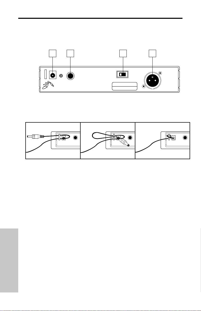
Recorrido Guiado - Panel trasero del VR3
1: Entrada DC - Conecte aquí el adaptador de corriente de 12 voltios y 250 mA que se
incluye, utilizando la pestaña anti-tirones tal como se ve en la ilustración de abajo.
ATENCION: No utilice ningún otro adaptador distinto a este; el hacer esto puede producir
serios daños en el VR3 y anulará su garantía.
2: Salida no balanceada* - Utilice este conector jack de 1/4” no balanceado de alta
impedancia (5K Ohm) cuando conecte el VR3 a aparatos de sonido no profesionales
(-10). El cableado es el siguiente: punta-activo, lateral-masa.
3: Interruptor de nivel de salida de audio - Ajusta la atenuación de nivel de salida audio
de la salida balanceada (vea #4 siguiente) a -20 dBm (nivel de línea) o -40 dBm (nivel de
micro). Vea la sección de “Ajuste y utilización del sistema VHF TD Series / VHF Series”
en la página 46 de este manual para más información.
4: Salida balanceada* - Utilice este conector XLR balanceado electrónicamente y de
baja impedancia (600 Ohm) cuando conecte el VR3 a unidades de audio profesional (+4).
El cableado de las puntas es el siguiente: punta 1 masa, punta 2 alto (activo) y punta tres
bajo (pasivo).
* Si es necesario, se pueden utilizar de forma simultánea tanto las salidas balanceadas
como no balanceadas.
44
Uso del gancho anti-tirones: Coja una pequeña vuelta de cable y pásela por el gancho, y después pase
el conector del adaptador por dentro de esta vuelta para formar un nudo.
ESPANOL
1
DC INPUT
AC CABLE LOCK
CABLE LOCK LOOP THRU AND TIE
+
CAUTION
USE SAMSON
AC ADAPTER
ONLY
2
UNBALANCED OUTPUT
-
-10 dB 5KΩ
S. No.
CH :
Non-Diversity Receiver
F:
3
BALANCED SWITCH
LINE
MIC
POWER RATING
DC 12V, 1.9W(160mA)
LINE:
-20dBm600Ω
MIC:
-40dBm600Ω
4
BALANCED OUTPUT
XLR:
①GND
②HOT
③COLD
-
Page 45

45
Recorrido Guiado - VT3L / VT3
1: Conector de entrada - Aquí se conecta la unidad de entrada. El VT3L viene con un
micrófono lavalier o de diadema (conectado a través de un conector jack XLR mini de tipo
Switchcraft), mientras que el VT3 viene con un cable conectado de forma permanente
que termina en una clavija de 1/4”. En la página 49 de este manual puede encontrar una
tabla de cableado que le muestra las conexiones de los micro lavalier y de diadema más
comunes.
2: Medidor de nivel de pila - Este grupo de tres pilotos LED multicolor indica la carga
relativa de la pila, marcando si la pila instalada está con una carga baja (en rojo), media
(amarillo) o alta (verde). Siempre que el VT3L o VT3 esté encendido estará iluminado uno
de estos pilotos (vea #5 en la página siguiente). Cuando se ilumina el indicador rojo de
“carga baja”, el rendimiento RF se va reduciendo y conviene que cambie la pila lo antes
posible.
3: Interruptor on-off de audio - Cuando se coloca en la posición “on” se transmite la
señal audio. Cuando se coloca en la posición “off”, la señal audio queda anulada. Dado
que la señal portadora sigue activa durante la anulación del audio, no se produce ningún
“petardeo” ni “chasquido”. Tenga en cuenta que el colocar en off este interruptor no hace
que se apague el transmisor—simplemente es una forma de anular temporalmente la
transmisión de la señal audio. Si piensa no utilizar el transmisor durante un periodo de
tiempo largo, apague el transmisor entero utilizando el interruptor on-off de encendido
(vea #5 en la página siguiente).
4: Cierres de la tapa de la pila - Pulse hacia dentro con cuidado sobre estas pestañas
para abrir la tapa de la pila del VT3L o VT3 y acceder así también al interruptor de
encendido on-off (vea #5 en la página siguiente) y al control de ganancia (vea #6 en la
página siguiente).
ESPANOL
AUDIO
INPUT
3
ON
▲
1
2
LOW MID HIGH
BATTERY
SAMSON
VT3
SAMSON
4
VHF BELTPACK TRANSMITTER
4
Page 46

46
Recorrido Guiado - VT3L / VT3
5: Interruptor on-off de encendido* - Utilice este interruptor para encender o apagar el
VT3L / VT3 (para mantener la pila durante más tiempo, asegúrese de dejar la unidad apagada cuando no la utilice).
6: Control de ganancia (ajuste giratorio) - Este control de sensibilidad de entrada ha
sido prefijado en fábrica para ofrecerle el nivel óptimo con el modelo de micro lavalier o de
diadema concreto que utilice (en el caso del VT3, viene prefijado para el mejor nivel de
instrumento) y por tanto le recomendamos que no lo ajuste manualmente. Si fuese
necesario hacerlo, no obstante, puede utilizar el destornillador de plástico que se incluye
(vea #8 más abajo) para disminuir o aumentar el nivel de entrada del VT3L / VT3. Vea la
sección de “Ajuste y utilización del sistema VHF TD Series / VHF Series” en la página 46
de este manual para más información.
7: Receptáculo de la pila - Coloque aquí una pila alcalina de 9 voltios standard,
asegurándose de seguir las indicaciones de colocación de los polos positivo y negativo.
Recomendamos las pilas del tipo Duracell MN 1604. Aunque se pueden usar también pilas
recargables de niquel-cadmio, estas no dan una corriente adecuada durante más de
cuatro horas.
ATENCION: No coloque la pila al revés; el hacerlo puede producir daños
graves en el VT3L / VT3 y anularía la garantía.
8: Destornillador de plástico - Diseñado especialmente para su uso en el ajuste del
control de nivel de entrada audio del VT3L / VT3 (vea #7 anterior) y/o el control Squelch
del receptor (vea #4 en las páginas 39 y 41). Vea la sección de “Ajuste y utilización del sistema VHF TD Series / VHF Series” en la página 46 de este manual para más información.
* Asegúrese de anular la señal audio en su mezclador o amplificador exterior antes de
encender o apagar el transmisor, o puede que se produzca algún chasquido audible.
ESPANOL
VT3
INPUT
SAMSON
6
GAIN
ON
POWER
▲
5
7
SAMSON
8
Page 47

47
Recorrido Guiado - VH3
1: Interruptor on-off de audio - Cuando se ajusta
a la posición “on”, la señal audio es transmitida.
Cuando se coloca en la posición “off”, la señal
audio queda anulada. Dado que la señal portadora
sigue activa durante la anulación de la otra, no se
escuchará ningún “petardeo” o “chasquido”. Tenga
en cuenta que al colocar este interruptor en “off”
no apagará la unidad—sencillamente es una forma
de anular o dejar en mute temporalmente la transmisión de la señal audio. Si piensa no usar el VH3
durante un periodo de tiempo largo, apague el
transmisor por medio del interruptor on-off de
encendido (vea #3 siguiente).
2: Medidor de nivel de pila - Este grupo de tres
pilotos LED multicolor indican la carga relativa de
la pila, marcando si la pila instalada está con una
carga baja (en rojo), media (amarillo) o alta
(verde). Siempre que el VH3 esté encendido
estará iluminado uno de estos pilotos (vea #3
siguiente). Cuando se ilumina el indicador rojo de
“carga baja”, el rendimiento RF se va reduciendo y
conviene que cambie la pila lo antes posible.
3: Interruptor on-off de encendido* - Utilice este interruptor para encender o apagar el
VH3 (para mantener más tiempo la carga de la pila, asegúrese de dejar este interruptor
en “off” cuando no utilice la unidad).
4: Control de ganancia (ajuste giratorio) - Este control de sensibilidad de entrada ha
sido prefijado de fábrica para ofrecerle el mejor nivel posible para la cápsula de micro
concreta que venga con su sistema VHF TD Series o VHF Series por lo que no le
recomendamos que lo ajuste manualmente a otra posición. No obstante, si fuese
necesario hacerlo, puede utilizar el destornillador de plástico que se incluye para
aumentar o disminuir el nivel de entrada. Vea la sección de ““Ajuste y utilización del sistema VHF TD Series / VHF Series” en la página 46 de este manual para más información.
5: Receptáculo de la pila - Introduzca aquí una pila alcalina de 9 voltios standard,
asegurándose de colocar correctamente los polos positivo y negativo según las marcas.
Recomendamos utilizar pilas del tipo Duracell MN 1604. Si bien es posible utilizar también
pilas de niquel-cadmio recargables, tenga en cuenta que no ofrecen una corriente a buen
nivel durante más de cuatro horas.
ATENCION. Nunca introduzca la pila al revés; esto
puede dañar el VH3 e invalidará la garantía.
* Asegúrese de anular la señal audio en su mezclador o amplificador exterior antes de
encender o apagar esta unidad, ya que en caso contrario puede que se produzca algún
chasquido audible.
ESPANOL
x
x
x
x
x
x
x
x
T
AUDIO
Ch2
2
C
A
N
A
D
A
:
X
X
X
X
X
X
X
X
X
1
SAMSON
ON
MIN
3
MAX
OFF
POWER
LEVEL
5
4
Z
B
3
OFF ON
H
V
R
C
C
LOW MID HIGH
D
BATTERY LEVEL
I
C
C
F
Page 48

48
Ajuste y utilización de su sistema VHF TD Series / VHF Series
El proceso básico de ajuste y utilización de su sistema VHF TD Series / VHF Series solo
conlleva unos pocos minutos:
1. Para que el sistema VHF TD Series / VHF Series funcione correctamente, tanto el
receptor como el emisor deberán estar ajustados al mismo canal. Separe todas las partes
del embalaje (y guárdelas por si fuese necesaria cualquier reparación en el futuro) y
asegúrese que el receptor y el transmisor que vienen dentro estén ajustados al mismo
canal. Si los canales no coincidiesen, contacte con su distribuidor o, si lo adquirió en los
Estados Unidos, con el servicio de asistencia técnica de Samson en el 1-800-372-6766.
2. Coloque físicamente el receptor en el lugar donde lo vaya a usar (por regla general
debe intentar mantener una “línea recta de visión” entre el receptor y el transmisor, de tal
forma que la persona que utilice o lleve el transmisor pueda ver en todo momento el
receptor). Un kit de montaje en rack opcional (disponible en su distribuidor) permite montar el VR3TD o VR3 en un rack standard de 19” si quiere. Extienda la antena o antenas y
colóquelas en posición vertical.
3. Asegúrese de que el interruptor on-off de encendido de su transmisor de petaca VT3L /
VT3 o del transmisor manual VH3 estén en “Off”.
4a. Si su sistema consta de un transmisor de petaca VT3L / VT3, pulse suavemente hacia
dentro en las pestañas de sujeción para abrir la tapa de la pila. Tenga en cuenta que esta
tapa tiene un gozne y no ha de ser separada de la carcasa del transmisor. Tenga cuidado
cuando abra esta tapa dado que puede dañar los goznes si utiliza demasiada fuerza.
4b. Si su sistema consta de un transmisor de micro manual VH3, desenrosque la sección
inferior del micro girándola hacia la izquierda y luego sepárela tirando hacia abajo.
5. Coloque en ambos casos una pila alcalina de 9 voltios nueva en el receptáculo de la
pila del transmisor, siguiendo las indicaciones de polaridad marcadas. Si está utilizando el
transmisor de petaca VT3L o VT3, vuelva a colocar la tapa de la pila empujando hasta
que oiga un “click”. Si utiliza el transmisor de micro VH3, vuelva a colocar la sección inferior del micro en su sitio deslizándola hacia arriba y volviéndola a enroscar. Sea cual sea
el transmisor que utilice, déjelo apagado por el momento.
6. Haga las conexiones de cables físicas entre el conector de salida del VR3TD o VR3 y
la entrada audio con nivel de micro o de línea que corresponda en su amplificador o
mezcladora. Si está utilizando una toma XLR balanceada (lo cual es preferible, dado que
desarrolla una señal electromagnéticamente más limpia), asegúrese de ajustar correctamente el interruptor de nivel de salida de audio del panel trasero del receptor. Si fuese
necesario, puede utilizar simultáneamente tanto las salidas balanceadas como las no
balanceadas. Llegados a este punto, deje su amplificador (y/o mezclador) apagado.
7. Gire el mando de volumen del VR3TD o VR3 completamente a la izquierda. Utilizando
el enganche anti-tirones, conecte el adaptador de corriente AC que viene incluido a la
entrada DC del panel trasero del receptor, y luego coloque el otro extremo en una salida
de corriente AC normal. Pulse el interruptor de encendido del panel frontal para encender
el VR3TD o VR3; el piloto verde “Power” se iluminará, si bien el resto de pilotos LED del
panel frontal seguirán apagados.
8. Encienda el transmisor VT3, VT3L o VH3 (utilizando el interruptor on-off de encendido);
el piloto verde “HIGH” de carga de pila se iluminará si la pila está suficientemente cargada. En este punto, se iluminará el piloto “TX” en el panel frontal del receptor. Si está usando un receptor VR3TD, se iluminará también el piloto amarillo “A” o “B” en el panel frontal,
dependiendo de cual sea la antena que esté recibiendo la señal más fuerte.
9. Ha llegado el momento de fijar los niveles audio. Conecte el amplificador y/o mezclador
que tenga conectado pero mantenga su volumen al mínimo. Luego, asegúrese de que su
transmisor no esté anulado ajustando su interruptor Audio a “On”. Ajuste luego la posición
ESPANOL
Page 49

49
Ajuste y utilización de su sistema
VHF TD Series / VHF Series
del mando de volumen del VR3TD o VR3 totalmente a la izquierda. Si está usando el
transmisor VH3 o si está utilizando el transmisor VT3L con un micro de diadema o lavalier
conectado, hable o cante en el micro a un nivel de ejecución normal a la vez que observa
el medidor de nivel AF del panel frontal del VR3TD o VR3. Si está utilizando el transmisor
VT3 con un instrumento conectado a él, toque en el instrumento a un nivel de ejecución
normal mientras observa el medidor de nivel AF del panel frontal del VR3TD o VR3. Si se
queda iluminado fijo el segmento “100%” (ganancia unitaria), con solo excursiones superiores ocasionales, entonces el nivel audio estará correctamente ajustado. Si no, utilice el
destornillador de plástico que se incluye para ajustar lentamente el control de ganancia del
VH3, VT3 o VT3L (mando giratorio) hasta que en el medidor de nivel AF del VR3TD o VR3
quede iluminado fijo el segmento “100%” (ganancia unitaria), con leves y ocasionales
excursiones superiores. Después aumente lentamente el mando de volumen del VR3TD o
VR3 a la posición de las dos en punto (ganancia unitaria) y, finalmente, ajuste el volumen
de su amplificador/mezclador hasta que consiga el nivel deseado. Si está utilizando un
transmisor de petaca VT3L con un micro lavalier, tenga en cuenta que la correcta
colocación del micro lavalier resulta crítica para la calidad de sonido a conseguir.
Recomendamos que lo sitúe tal y como le mostramos en esta ilustración—tan cerca de
sus labios como pueda pero desplazado hacia un lado (para reducir al mínimo el efecto
nasal) y evitando que ninguna ropa interfiera. Tenga en cuenta también que los micrófonos
omnidireccionales (micros que captan la señal en todas las
direcciones) son más propensos a dar problemas de feedback
o realimentación que los unidireccionales (cardioicos o
supercardioicos); por lo general, podrá evitar la realimentación
teniendo cuidado de no colocar ningún micrófono directamente
delante de un altavoz PA (en caso de que esto sea imposible,
pruebe a utilizar un ecualizador para atenuar esas frecuencias
de rangos medio y alto que son las causantes del “pitido” de
realimentación).
10. Si escucha alguna distorsión al nivel de volumen elegido
(o si se enciende con demasiada frecuencia el segmento LED “125%” en el medidor de
nivel AF), primero compruebe que el interruptor de nivel de salida audio del panel trasero
del VR3TD o VR3 esté correctamente ajustado. Luego, asegúrese de que la estructura de
ganancia de su sistema de audio haya sido ajustada correctamente (consulte el manual de
instrucciones de su mezclador y/o amplificador). Si escucha cualquier distorsión, haga lo
siguiente:
• Si está usando un transmisor manual VH3 o un transmisor VT3L con un micro lavalier
o de diadema conectado, le recordamos que su control de ganancia ha sido ajustado
en fábrica para ofrecerle el mayor nivel para el modelo de micro concreto que esté
usando, por lo que no es necesario ningún ajuste. Por esta razón, cualquier distorsión
que se produzca simplemente será cuestión de un micro colocado demasiado cerca de
la boca; pruebe a alejarlo un poco. Si esto no arregla el problema, utilice el destornillador que se incluye para girar lentamente a la izquierda el control de nivel de ganancia
(ajuste giratorio) del VH3 o VT3L hasta que desaparezca la distorsión.
• Si está utilizando el transmisor VT3 con un instrumento como una guitarra o un bajo
eléctrico, disminuya el nivel de salida del instrumento hasta que desaparezca la distorsión. De forma alternativa, puede utilizar el destornillador de plástico para girar lentamente a la izquierda el control de ganancia (ajuste giratorio) hasta que desaparezca la
distorsión.
Tenga en cuenta que, tras realizar este proceso de ajuste, siempre puede disminuir el
mando de volumen del VR3TD o VR3 para atenuar la señal de salida.
ESPANOL
VT3L
VHF BELTPACK TRANSMITTER
INPUT
SAMSON
Page 50

50
Ajuste y utilización de su sistema
VHF TD Series / VHF Series
11. De forma opuesta, si escucha en la salida una señal ruidosa y débil al nivel de
volumen que haya elegido (y con el control de volumen del receptor girado a tope a la
derecha), asegúrese nuevamente de que la estructura de ganancia de su sistema de
sonido haya ajustada correctamente. Si todo esto estuviese bien y la señal que viene del
VR3TD o VR3 siguiese siendo débil y/o con ruidos, haga lo siguiente:
•Si está utilizando un transmisor VH3 o VT3L con un micro lavalier o de diadema
conectado, hay que tener en cuenta que su control de nivel ha sido ya fijado previamente
en fábrica para ofrecer el mejor nivel posible para el micro concreto que se utilice, por lo
que no debería ser necesario hacer más ajustes. Cualquier debilidad en la señal debería
ser motivada por tanto por una colocación demasiado lejana del micro con respecto a los
labios; pruebe a colocarlo más cerca. Si esto no le soluciona nada, utilice el
destornillador que se incluye para girar lentamente hacia la derecha el control de
ganancia del VH3 o VT3L hasta que la señal quede a un nivel que considere aceptable.
• Si está utilizando un transmisor VT3 con un instrumento del tipo de una guitarra o bajo
eléctrico conectado, aumente el nivel de salida del instrumento hasta conseguir una
señal razonable. De forma alternativa, también puede utilizar también el destornillador
para girar el control de ganancia (ajuste) del VT3 lentamente hacia la derecha hasta
hacer que la señal llegue a un nivel aceptable.
12. Disminuya al mínimo temporalmente el nivel de su sistema mezclador/amplificador y
apague su transmisor, dejando el VR3TD o VR3 encendido. Después vuelva a colocar el
nivel ajustado previamente en su amplificador/mezclador. Con el transmisor apagado, el
receptor debería estar totalmente en silencio—si es así, pase al punto siguiente. Si no
ocurre esto (es decir, si escucha algún tipo de ruido), puede que deba ajustar el control
Squelch del panel frontal del receptor. Cuando este control está en su ajuste mínimo, el
sistema VHF TD Series / VHF Series siempre permite un rango máximo sin cortes ni caí-
das; no obstante, dependiendo del entorno concreto en el que utilice su sistema, puede
que tenga que reducir algo este rango para eliminar el ruido de banda que aparece cuando
el transmisor está apagado. Para hacerlo, utilice el destornillador que se incluye para girar
el control Squelch completamente a la izquierda (hasta la posición “Min”), y luego vaya
subiendo lentamente la posición a la derecha hasta que el ruido desaparezca. En caso de
que no se produjese ningún ruido en ninguna posición, deje este control en su posición
“Min” de más a la izquierda (para tener el mayor rango posible).
13. Cuando ajuste su sistema VHF TD Series / VHF Series por primera vez en un entorno
o ambiente nuevo, siempre resulta una buena idea dar una vuelta por el lugar para
asegurarse de la cobertura que tiene en toda la zona de ejecución. De acuerdo a ello,
disminuya el nivel de su sistema audio y encienda tanto el transmisor como el receptor.
Luego, con el transmisor activo (es decir sin anulación), restaure el nivel de su sistema
audio y a la vez que va hablando o cantando, o tocando su instrumento, vaya andando por
toda la zona que deba cubrir. Mientras lo hace, debería ver el piloto “TX” iluminado
siempre en el panel frontal del VR3TD o VR3. Si está usando un sistema VR3TD, debería
ver siempre iluminado uno de los pilotos amarillo “A” y “B” en el receptor VR3TD,
ocasionalmente cambiando de uno a otro para indicarle cual de las antenas está
recibiendo la señal más fuerte de las dos. Intente siempre reducir al mínimo la distancia
entre el transmisor y el receptor para conseguir recibir siempre la señal más potente
posible desde cualquier punto de transmisión. En instalación fijas como en salas de A/V o
salones de conferencias o para aplicaciones de rango ampliado (en las que el transmisor y
el receptor están separados más de 50 metros), puede que le resulte recomendable
colocar las antenas en un ángulo diferente a la vertical o colocar el receptor en la misma
sala que los transmisores (y, si fuese necesario, alargar los cables que van a los aparatos
exteriores de audio).
ESPANOL
Page 51

MANUFACTURER MODEL PIN 1 PIN 2 PIN 3
AKG C410
SHIELD
WHITE JUMP TO PIN 2
RED
AUDIO TECHNICA AT831
YELLOW x 2
RED x 2 JUMP TO PIN 2
SHIELD
AUDIO TECHNICA ATM75
YELLOW x 2
RED x 2 JUMP TO PIN 2
SHIELD
AUDIO TECHNICA ATPRO8HE
YELLOW x 2
N/C RED x 2
SHIELD
AUDIO TECHNICA ATPRO35X
YELLOW x 2
RED x 2 JUMP TO PIN 2
SHIELD
AUDIO TECHNICA MT350
SHIELD WHITE JUMP TO PIN 2
CROWN CM311(E)
SHIELD
RED JUMP TO PIN 2
WHITE
SONY ECM44
SHIELD
RED JUMP TO PIN 2
WHITE
SONY ECM55
SHIELD
RED JUMP TO PIN 2
WHITE
SONY ECM77
SHIELD
RED JUMP TO PIN 2
WHITE
SONY ECM144
SHIELD WHITE JUMP TO PIN 2
SENNHEISER MKE2
SHIELD
JUMP TO PIN 2
BLUE
RED
SENNHEISER MKE40
SHIELD
JUMP TO PIN 2
BLUE
RED
SENNHEISER MKE48
SHIELD
JUMP TO PIN 2
BLUE
RED
SAMSON ECM40
SHIELD WHITE JUMP TO PIN 2
COUNTRYMAN ISOMAX
SHIELD WHITE JUMP TO PIN 2
GUITAR
SHIELD N/C AUDIO
PIN INFORMATION
SWITCHCRAFT
GROUND +Vdc AUDIO
TA3F
Procedure for wiring VT3L connector: Unscrew rubber boot 1 and pass
wire through 1 and 2. Solder wire to 3 after removing from 4 (use chart
above). Reinsert 3 to 4 with attached wire (3 is keyed to fit 4). Plug 2 into
3 again (2 is keyed to 3) and crimp wire. Rescrew rubber boot 1 to 4.
Appendix A: VT3L Multipin
Wiring Guide and Chart
51
1 2 3 4
SWITCHCRAFT TA3F
Page 52

Appendix B: Carrying Case
To ensure the longevity of your VHF TD Series / VHF Series system, and for convenience
when on the road, your VHF TD Series / VHF Series system includes an impact-resistant
polypropylene plastic carrying case with foam rubber padding. As shown in the illustration
below, custom cutouts in the interior padding provide secure placement for all components
in your system.
52
SAMSON
Page 53

53
Transmitter / Emetteur / Sender / Transmisor (VT3L, VT3 and VH3):
Transmission Mode Frequency modulation, 80KF3E, 20 kHz peak deviation
Frequency Range 173.80 MHz to 213.20 MHz, 25 frequencies
Band A (European / UK models) 160.10 to 177.90 MHz
Band B (European / UK models) 189.10 to 210.10 MHz
OSC System Crystal controlled, x9 multiplication
RF Power 20 mW (USA models), 2 mW (European / UK models)
Operating Range 300 ft.
Frequency Stability ± 10 ppm
Approvals Complies with ETS 300 422 and FCC Part 74
Radiating Harmonic and Spurious Emission Below limits of applicable regulations
Antenna Type Internal
Audio Frequency Response 40 Hz to 16 kHz ±3 dB
Pre-Emphasis 50 µSec
Noise Reduction System NE571 based compandor
Signal To Noise Ratio > 100 dB
Maximum Input Level 0 dBv (VT3L, VT3), -20 dBv (VH3)
T.H.D. < 1% @ 1 kHz
Current Consumption 32 mA (typical)
Battery Life (MN1604 9-volt alkaline) 14 hours (typical)
Operating Temperature -10 to +55 degrees C
Controls
VT3L / VT3 Power On/Off, Mute On/Off, Level Control (Trimpot)
VH3 Power On/Off, Audio On/Off, Level Control (Trimpot)
LED Indicator Battery high/medium/low
Dimensions
VT3L / VT3 65 (W) x 22 (H) x 100 (D) mm (2.6 x .87 x 4 in.)
VH3 37 (W) x 240 (H) mm (1.46 x 9.45 in.)
Weight 110 grams • 3.9 oz.
Receiver / Récepteur / Empfänger / Receptor (VR3TD and VR3):
Receiving System
VR3TD Single conversion Superheterodyne, Microprocessor True Diversity*
VR3 Single conversion Superheterodyne, Non-Diversity
Frequency Range 173.80 MHz to 213.20 MHz, 25 frequencies
Band A (European / UK models) 160.10 to 177.90 MHz
Band B (European / UK models) 189.10 to 210.10 MHz
Receiving Mode 80KF3E
Sensitivity < 3 µV for 20 dB SINAD, < 10 µV for 50 dB S/N
Selectivity 120 kHz BW, nominal @ -6 dB, ± 300 kHz (adj CH), -75 dB
Squelch Sensitivity 2.5 µV to 250 µV adjustable
IF 10.7 MHz
Local Oscillator System Crystal controlled
Noise Reduction System NE571 based compandor
De-emphasis 50 µsec.
Signal To Noise Ratio > 100 dB (IHF-A) line out, >90 dB (IHF-A), mic out
Audio Frequency Response 40 Hz to 16 kHz ±3 dB
T.H.D. < 1% @ 1 kHz
Audio Output Levels -10 dB unbalanced (1/4" phone connector),
-20 dBm / -40 dBm balanced (XLR connector)
Audio Output Impedance 5 kΩ unbalanced, 600 Ω balanced
Antennas 1/4 wavelength telescopic
Operating Temperature -10 to +55 degrees C
Controls Volume, Squelch, Power
LED Indicators
VR3TD TX On / Antenna A or B (2 LEDs) / Power / AF Level (5 LEDs)
VR3 TX On / Power/ AF Level (5 LEDs)
Power Requirement 12 Volts DC, 80 mA typical (160 mA max.), AC adapter supplied
Dimensions (W x H x D, without antennas) 215 x 44 x 80 mm (8.5 x 1.75 x 3.2 in.)
Weight (including antennas) 300 g • 0.7 lb.
Unit conforms
* US Patent 5,465,411
Specifications
Page 54

FCC Rules and Regulations
Samson wireless systems are type accepted under
FCC rules parts 90, 74 and 15.
Licensing of Samson equipment is the user’s
responsibility and licensability depends on the user’s
classification, application and frequency selected.
This device complies with RSS-210 of
Industry & Science Canada.
Operation is subject to the following two conditions:
(1) this device may not cause harmful interference
and (2) this device must accept any interference
received, including interference that may cause
undesired operation.
 Loading...