

Page 1
S C l a s s S i g n a l P r o c e s s o r s
4 INPUT 4 ZONE STEREO MIXER
Page 2

Safety Instructions/Consignes de sécurité/Sicherheitsvorkehrungen/Instrucciones de seguridad
ACHTUNG:
Um die Gefahr eines Brandes oder Stromschlags zu verringern, sollten
Sie dieses Gerät weder Regen noch Feuchtigkeit aussetzen.Um die Gefahr eines
Stromschlags zu verringern, sollten Sie weder Deckel noch Rückwand des Geräts ent-
fernen. Im Innern befinden sich keine Teile, die vom Anwender gewartet werden kön-
nen. Überlassen Sie die Wartung
qualifiziertem Fachpersonal.
Der Blitz mit Pfeilspitze
im gleichseitigen Dreieck soll den Anwender vor nichtisolierter “gefährlicher Spannung”
im Geräteinnern warnen. Diese Spannung kann so hoch sein, dass die Gefahr eines
Stromschlags besteht. Das Ausrufezeichen im gleichseitigen Dreieck soll den Anwender
auf wichtige Bedienungs- und Wartungsan leitungen aufmerksam machen, die im mit-
gelieferten Informationsmaterial näher beschrieben werden.
Wichtige Sicherheitsvorkehrungen
facturers instructions.
for your safety. When the provided plug does not fit your outlet, consult an electri-
Pour éviter tout risque d’électrocution ou d’incendie, ne pas exposer
Pour éviter tout risque d’électrocution, ne pas
fiées. Si votre prise murale ne correspond pas au modèle fourni, consultez votre
jection liquide dans l’appareil, introduction d’un objet dans le boîtier, etc.).
Page 3

www.samsontech.com
the S zone
C
C
Usng the Ducker-Switch Chart 17
Page 4

The S zone is a professional quality 4-channel zone mixer
you’ll find a convenient two-band equalizer allowing you
jack, level control and internal super speaker allow you to
Page 5

Volume control, Stereo/Mono switch and our dedi-
The Samson S zone four-channel stereo zone mixer utilizes state-of-the-art, high quality audio circuit technol-
Page 6
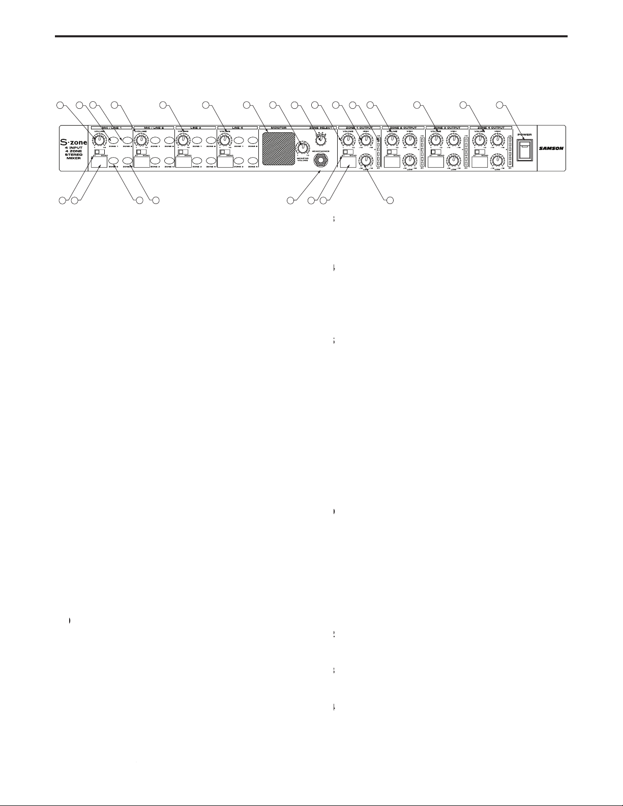
1 VOLUME
– Rotary control used to adjust the level of
2 ZONE 1
– When the LED Backlit switch is pressed
3 ZONE
– When the LED Backlit switch is pressed in,
4 STEREO/MONO
- This switch is used to
5 SCRIBE STRIP
– Convenient area for marking the
6 ZONE 3
– When the LED Backlit switch is pressed in,
7 ZONE 4
– When the LED Backlit switch is pressed in,
8 MIC/LINE 2
– Channel 2 input with the same knob
9 LINE 3
– Channel 3 input with the same knob and
LINE 4
– Channel 4 input with the same knob and
11 MONITOR SPEAKER
– This built-in, miniature super-
12 MONITOR VOLUME
- This rotary control is used
ZONE SELECT switch
– This four-position switch is
HEADPHONE JACK
- Connect any standard stereo
15
VOLUME
– This rotary control is used to control the
16
HIGH
– High frequency equalizer rotary control
OUTPUT METER
– Six-segment LED meter display-
18
STEREO/MONO switch
- This switch is used to
19
SCRIBE STRIP
– Convenient area for marking the
20
LOW
ZONE OUTPUT 2
– ZONE 2 OUTPUT with the same
ZONE OUTPUT 3
– ZONE 3 OUTPUT with the same
ZONE OUTPUT 4
– ZONE 4 OUTPUT with the same
POWER switch
Page 7
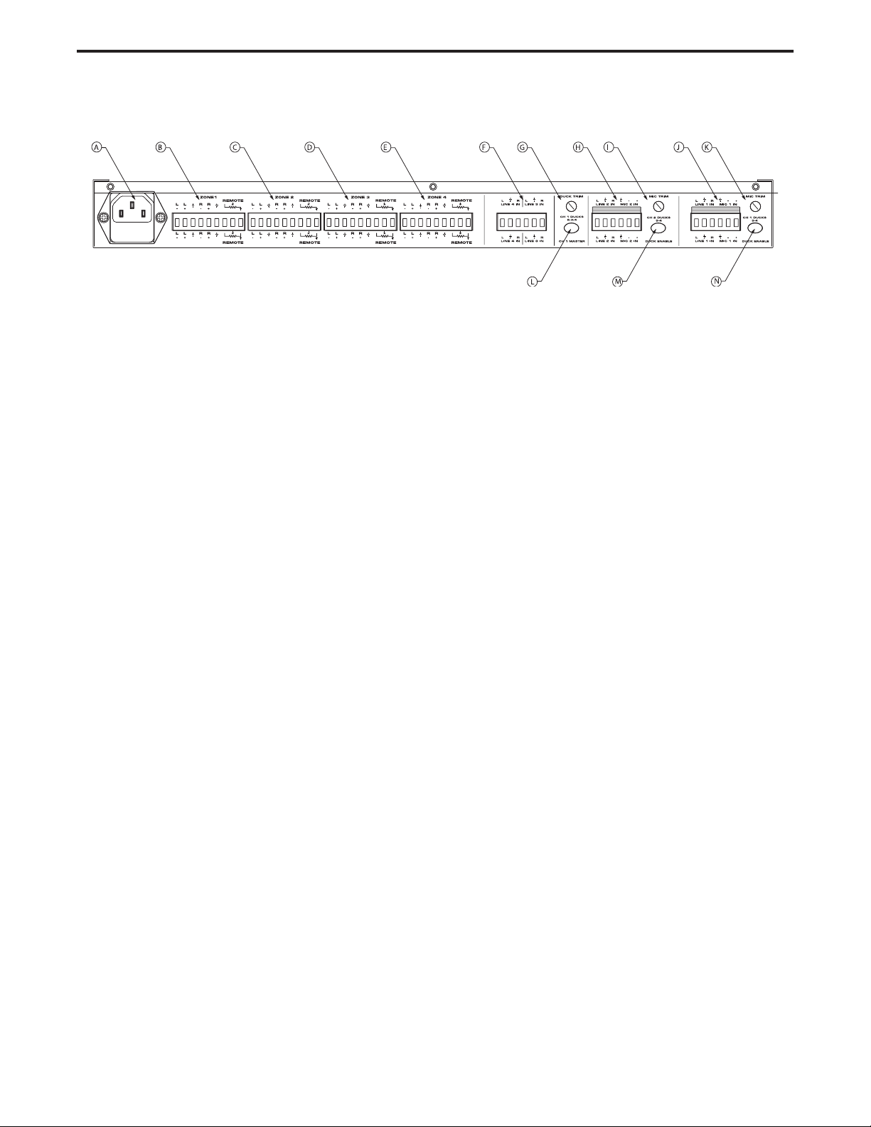
I MIC TRIM
– The rotary control is used to adjust
J MIC/LINE 1
– This connector includes the con-
K MIC TRIM
– The rotary control is used to adjust
L CH 1 MASTER switch
– This switch is used to
M DUCK ENABLE
N DUCK ENABLE
– Channel 1 will act as a duck-
signal on Channel 1.
A AC INPUT FUSE HOLDER
– Connect the supplied 3-
B ZONE 1 OUTPUT
C ZONE 2 OUTPUT
– This connector includes the Zone
D ZONE 3 OUTPUT
– This connector includes the Zone
E ZONE 4 OUTPUT
– This connector includes the Zone
F LINE 3 AND 4 INPUT
- This connector is used to
G DUCK TRIM
– This rotary control is used to adjust
H MIC/LINE 2
– This connector includes the connec-
Page 8

your installation plan you need to consider several design
The S zone provides four input channels with the ability
TV monitors, Radio Tuners, DJ mixers or any other line level
you should consider using an equipment rack, such as the
To select the speakers you need to consider a few impor-
you need to run a 70-volt distributed sound system. The
Page 9

you are making direct connection from the amplifiers in the
Page 10

you start connecting your S zone. If you’re a professional
pair of active (self powered) speakers. If you are using passive
speakers, the S zone’s ZONE OUTPUT should be connected to
Page 11

set too high, the channel will distort. Use your ears to set the
you may need to lower the ZONE OUTPUT VOLUME control, or
you may want to turn the power amp all the way up, and
You may also need to lower the
ZONE OUTPUT VOLUME control, or the power amp's volume
so that the VU Meter reads about 0 dB. Then adjust the vol-
VOLUME control knob on CHANNEL 1 to the 0 posi-
Page 12

These inputs are set to accept –10 dBV levels, which is the
These inputs are set to accept –10 dBV levels, which is the
The S zone’s rear panel is where you will find all (except the
The microphone inputs accept low impedance (100 to 600
the S zone
Input Wiring for Channel 3 and
Input Wiring for Channel 1 and
Page 13

you run a balanced wire you benefit from CMR (Common
To connect the Zone Outputs to a balanced input using
To connect the S zone’s Zone Outputs to an unbalanced
Zone Output Balance Line
Input Wiring for Channel 1 and
Zone Output Unbalance Line
Page 14

The S zone provides four stereo inputs that can also be set
The S zone’s inputs are laid out in four separate input strips
The S zone is a stereo device and thanks to the STEREO/
To learn more of output using stereo and mono outputs
“Setting the Outputs for Stereo or Mono”
The S zone channel input strips each have assignment
you can test the signals by using the S zones MONITOR
put
Page 15

The following section explains a simple procedure to route
switch to the Zone that you
speaker or headphones as you change the ZONE SELECT
switch.
The S zone features a unique monitor section located in
The
ZONE SELECT
is a four-position switch used to assign
Output Volume Control Kn
Page 16

Then, follow these steps.
and look for the level display on the
The S zone has four output zones, which are controlled
The S zone is a stereo device and thanks to the STEREO/
Zone Output
Zone Output
Page 17

To set the Zone Output equalizer for vocal operation you
To set the Zone Output equalizer for music playback you
program material (music or speech) that will ultimately be
great with little or no added equalization on the Zone Output.
system in any sound zone. If you do not have an analyzer, use
your ears and adjust the equalization to a setting that sounds
good to you.
The LOW Frequency EQ control provides up to 12 dB of
The next section explains how to apply some common
EQ Contour
Zone Output Equalizer
Page 18

The S zone allows you to set up a sophisticated music and
The S zone can use either Channel 1, 2 or even Channel 1
The next section details the operation of the DUCK EN-
TRIM control. Once there is no input present on Channel 1,
TRIM control
you can use the CHANNEL 1 MASTER switch so that Chan-
Page 19

The diagram below shows the possible settings for using
Page 20

®
®
®
®
®
®
Page 21

S zone’s Four Room Set-up
A/V monitor is connected to the line input on channel 3. The microphones connected to the S zone channel 1 and 2’s input are set to duck the music playing in each of the zones.
Page 22

There are several ways to interface the S zone, depending on your exact monitoring set-up. Follow the cable diagrams
Mic Input Wiring for Channel 1 and 2
Input Wiring for Channel 1 and
2
Input Wiring for Channel 3 and
4
Input Wiring for Channel 3 and
4
Page 23

Mic 600Ω XLR balanced
Line 22K Ω
Mic -14 dBV balanced
Line +24 dBV
Mic 60 dB
Line 26 dB
Balanced 200 Ohms
Unbalanced 100 Ohms
THD <.02%
Tone Controls
LOW +/- 15 dB at 100 Hz
HIGH +/- 15 dB at 10 kHz
Inputs 6 PIN Euroblock
Outputs
PIN Euroblock
Mains Voltages/selectable USA/Canada ~120 V AC, 60 Hz
U.K./Australia ~240 V AC, 50 Hz
Europe ~230 V AC, 50 Hz
200-240 V AC: 125 mA (slow-blow)
19 in. (w) x 7.5 (d) x 1.75 (h)
482 mm (w) x 190 (d) x 44 (h)
5.1 lb. (2.31 kg)
Page 24

Page 25

Page 26

Page 27

Page 28

www.samsontech.com
 Loading...