

Samson SCOM User Manual

S Class Signal Processors
STEREO COMPRESSOR
STEREO
COMPRESSOR
GAIN REDUCTION dB INPUT / OUTPUT LEVEL dB
30 24 2127 18 15 9 612 4 2 1 -30 -18-12-24 -6 -3 +3 +60 +9 +12 +18
THRESHOLDTRIGGER RATIO ATTACK RELEASE OUTPUT ENHANCER
-10
10
GATE KEY
050
-30
FAST
SLOW
dB
RELEASE SPECTRA KEY AUTO I/O METER
OFF +10
20
dB
COMPRESSOR / LIMITEREXPANDER/GATE
4:1
50
LISTEN
62
+10
1
+20-40
.3 300
mSec
dB
GAIN REDUCTION dB INPUT / OUTPUT LEVEL dB
20015
.05 5
-10
+20-20
dB
Sec
0
1
3.15
STEREO LINK
5
IN/OUT 1
73
+10
OFF 10
IN/OUT 2
30 24 2127 18 15 9 612 4 2 1 -30 -18-12-24 -6 -3 +3 +60 +9 +12 +18
THRESHOLDTRIGGER RATIO ATTACK RELEASE OUTPUT ENHANCER
-10
10
20
GATE
GATE KEY
050
-30
FAST
OFF +10
SLOW
dB
RELEASE
4:1
+10
1
+20-40
dB
dB
SPECTRA KEY AUTO I/O METER
COMPRESSOR / LIMITEREXPANDER/GATE
50
LISTEN
62
20015
.3 300
mSec
.05 5
0
1
3.15
-10
+10
+20-20
dB
Sec
Sec
OFF 10
CH 2
CH 2CH 1
POWER
5
73
1
Safety Instructions
Caution: To reduce the hazard of electrical
shock, do not remove cover or back.
No user serviceable parts inside. Please refer all
servicing to qualified personnel.
WARNING: To reduce the risk of fire or electric shock, do not expose this unit to rain or moisture.
The lightning flash with an arrowhead symbol within an equilateral triangle, is intended to alert the user to the
presence of uninsulated "dangerous voltage" within the products enclosure that may be of sufficient magnitude
to constitute a risk of electric shock to persons.
The exclamation point within an equilateral triangle is intended to alert the user to the presence of important
operating and maintenance (servicing) instructions in the literature accompanying the product.
Important Safety Instructions
1. Please read all instructions before operating the unit.
2. Keep these instructions for future reference.
3. Please heed all safety warnings.
4. Follow manufacturers instructions.
5. Do not use this unit near water or moisture.
6. Clean only with a damp cloth.
7. Do not block any of the ventilation openings. Install in accordance with the manufacturers instructions.
8. Do not install near any heat sources such as radiators, heat registers, stoves, or other apparatus
(including amplifiers) that produce heat.
9. Do not defeat the safety purpose of the polarized or grounding-type plug. A polarized plug has two
blades with one wider than the other. A grounding type plug has two blades and a third grounding
prong. The wide blade or third prong is provided for your safety. When the provided plug does not fit
your outlet, consult an electrician for replacement of the obsolete outlet.
10. Protect the power cord from being walked on and pinched particularly at plugs, convenience receptacles and at the point at which they exit from the unit.
11. Unplug this unit during lightning storms or when unused for long periods of time.
12. Refer all servicing to qualified personnel. Servicing is required when the unit has been damaged in
any way, such as power supply cord or plug damage, or if liquid has been spilled or objects have fallen into the unit, the unit has been exposed to rain or moisture, does not operate normally, or has
been dropped.
ENGLISH
FOR CONTINUED PROTECTION AGAINST RISK
OF FIRE, REPLACE ONLY WITH SAME TYPE FUSE
CAUTION
ATTENTION
UTILISER UN FUSIBLE DE
RECHANGE DE MÊME TYPE
WARNING
DO NOT EXPOSE THIS EQUIPMENT
TO RAIN OR MOISTURE
AVIS
RISQUE DE CHOC ELECTRONIQUE
NE PAS OUVRIR
RISK OF ELECTRIC SHOCK
DO NOT OPEN

ENGLISH
Forward by Ray Kennedy 3
Introduction 4
S•com Features 5
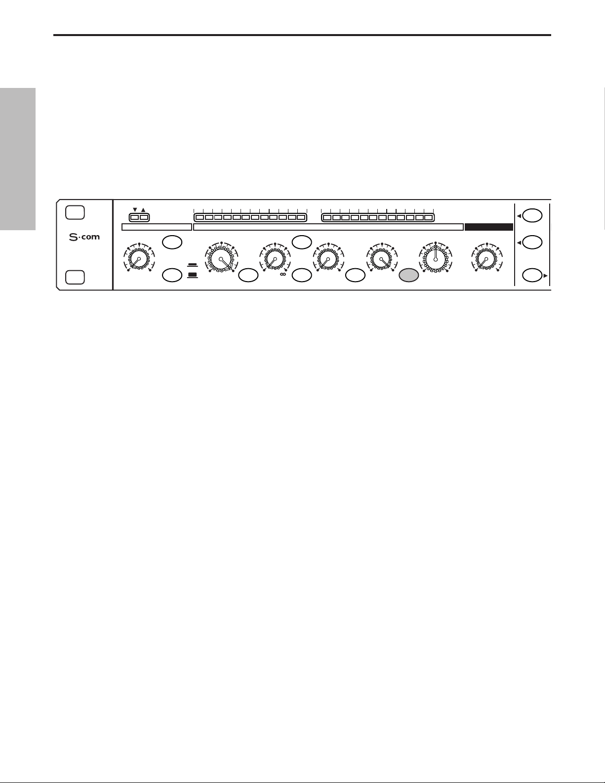
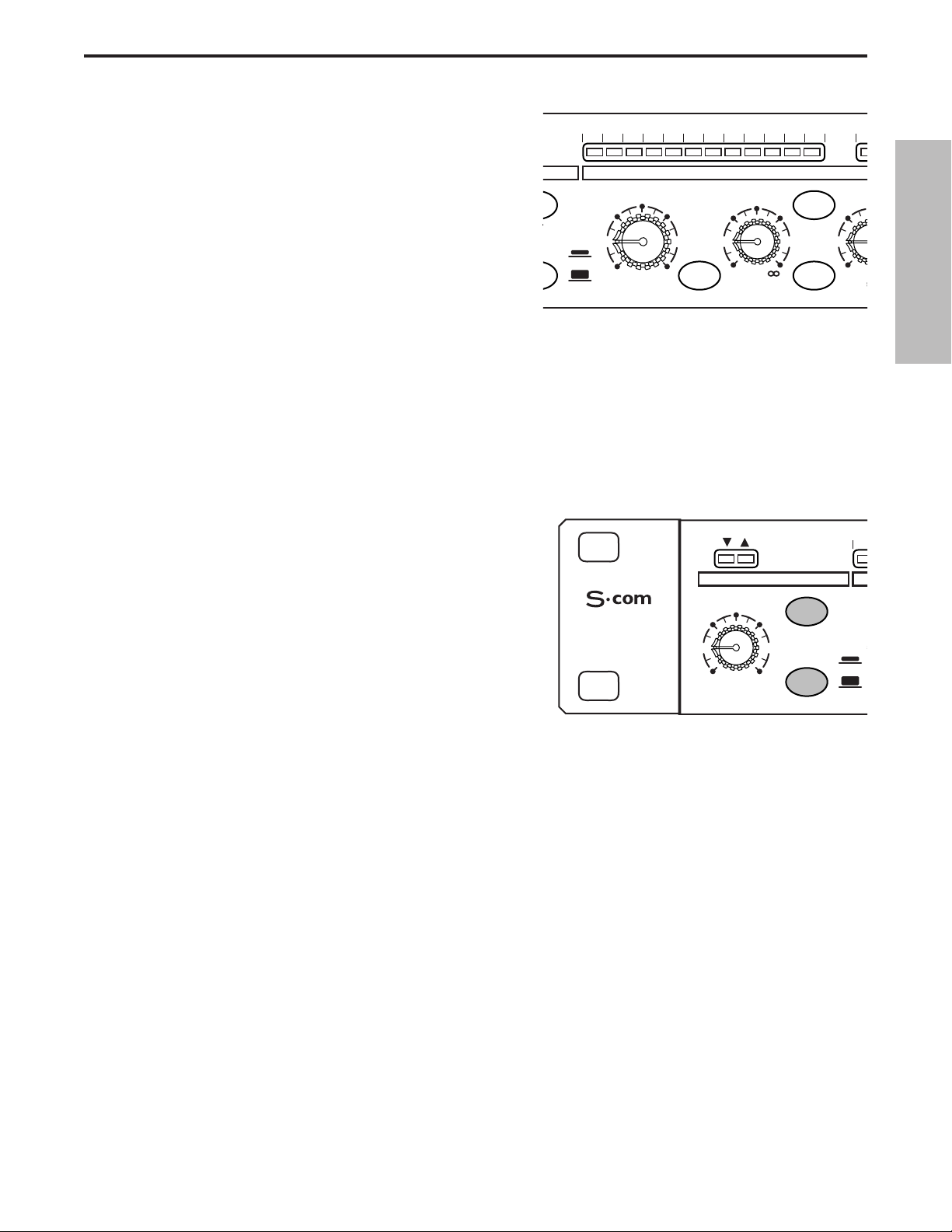
Controls and Functions
Front Panel Layout 6-7
Rear Panel Layout 6-7
Operating the S•com
Setting Up the S•com 8
Compressing A Signal 8
Gating A Signal 9
Using The Expander 9
Using the Spectra 10
Using the Enhancer 10
Dynamics Processing 101 11-12
Applications 13-14
System Set-ups 15-16
S•com Connections 17
Specifications 60-61
Block Diagram 62
Copyright 2001, Samson Technologies Corp.
Printed May, 2001
Samson Technologies Corp.
575 Underhill Blvd.
P.O. Box 9031
Syosset, NY 11791-9031
Phone: 1-800-3-SAMSON (1-800-372-6766)
Fax: 516-364-3888
www.samsontech.com
Table of Contents
Table des matières Inhalt Contenido
DEUTSCHE
Vorwort von Ray Kennedy 32
S•com Features 33
Regler und Funktionen
Vorderseite 34-35
Rückseite 34-35
Bedienung des S•com
S•com einrichten 36
Signal komprimieren 36
Signal gaten 37
Expander einsetzen 37
Expander einsetzen 38
Enhancer einsetzen 38
Dynamikbearbeitung 101 39-40
Anwendungen 41-42
System-Einrichtungsbeispiele 43-44
S•com Anschlüsse 45
Technische Daten 60-61
ESPAÑOL
Prólogo de Ray Kennedy 46
Características y funciones del S•com 47
Controles y funciones
Distribución del panel frontal 48-49
Distribución del panel posterior 48-49
Utilizar el S•com
Preparar el S•com 50
Comprimir una señal 50
Aplicar una compuerta a una señal 51
Utilizar el Expander 51
Utilizar el Spectra 52
Utilizar el Enhancer 52
Procesamiento de la dinámica 101 53-54
Aplicaciones 55-56
Instalaciones del sistema 57-58
Conexiones del S•com 59
Especificaciones 60-61
FRANÇAIS
Note de Ray Kennedy 18
Caractéristiques du S•com 19
Réglages et fonctions
Face avant 20-21
Face arrière 20-21
Utilisation du S•com
Configuration du S•com 22
Compression d’un signal 22
Utilisation du Noise Gate 23
Utilisation de l’expanseur 23
Utilisation du circuit Spectra 24
Utilisation de l’Enhancer 24
Éléments de base sur les processeurs de
dynamique 25-26
Applications 27-28
Configurations du système 29-30
Connexions du S•com 31
Caractéristiques techniques 60-61

3
Forward By Ray Kennedy
The use of compressors and limiters in recording and mixing are some of the most important
tools available and much more useful than many realize. To me, compression is much more of a
sound than a dynamics control device. Each model has its own sound and ideal application which
is why I have about forty units to choose from. Learning which type of unit and what settings to use
takes a lot of trial and experimentation but eventually you’ll find the best applications.
Peak limiting and soft compression are basically good for maximizing levels to tape or disk without a lot of coloration. Essentially knocking the peaks down and bringing the quieter portions of a
sound up louder by narrowing the dynamic range.Slow attack and fast release times allow for more
transparent sound. I personally like the sound of compression and use it at times to extremes.
Depending on the type of unit and the settings, so many tonal characters can be achieved from
thickening, adding ambience, toughening, softening, equalizing and much more. My favorite 'manic
compression"' trick is to make vocals feel suspended in the mix, dry and intimate, as if the singer
is right there in your face but not too loud. My partner Steve Earle says the amount of compression
we use on the vocals on his records lets people know what he had for breakfast.
In many ways, it becomes a replacement for reverb and used in extreme, it pulls in all the ambience
around a vocal mic as well as digging out character from down in your vocal cords. On an overhead
or room mic, you can actually change the perceived size of the room by making it suck in the decaying sound as it travels away. Again slow attack and fast release times will bring the best results
because you can hit the threshold much harder.
Stereo bus limiting and compression is also a very good method for actually gluing tracks together
and making bands sound tighter than they really are. It also allows for more saturation to analog
two track as well as fuller modulation to digital formats. For me, it is not unusual to hit three stereo
limiters before getting to the hard disk in mastering, which the final parts will be cut from.
Quite often running a signal through several compressors will allow some interesting results which
cannot be achieved with one unit.There certainly are no rules but it is important to know that there
are many different designs in squashing sound. Some are entirely tube, some tube and optical, just
optical, FET transistors, VCA's (voltage control amplifiers) Pure Class A, Class A/B, Digital, as well
as other combinations.
Now, we have finally arrived in an age of very high quality VCA's which are not too expensive and
are allowing for very sophisticated and versatile designs, as are the S-Class units from Samson.
Ray Kennedy
Ray Kennedy is a Nashville based Producer, Engineer and
Songwriter whose production company Twang Trust, a partnership between Ray and singer songwriter Steve Earle, has been
credited with well known artist recordings and performances
including Steve Earle, Art Garfunkel, Willie and Waylon, Farm
Aid, The Del McCoury Band, Nancy Griffith, Lucinda Williams,
David Alan Coe, Shaver, V-Roys, and Rosie Flores.
ENGLISH

4
Thank you for purchasing the Samson S•com dynamics processor. The Samson S•com is
a one-space dual channel dynamics processor optimized for recording, live sound reinforcement systems, DJ set-ups and commercial installations. The S•com is a complete dynamics
processing solution offering two channels of full function Compressor, Expander/Gate,
Spectra and Enhancer. S•com’s convenient meters provide instant status of important gain
management settings.
In these pages, you’ll find a detailed description of the features of the S•com dynamics
processor, as well a description of its front and rear panels, step-by-step instructions for its
setup and use, and full specifications.You’ll also find a warranty card enclosed—please
don’t forget to fill it out and mail it in so that you can receive online technical support and so
we can send you updated information about these and other Samson products in the future.
With proper care and adequate air circulation, your S•com will operate trouble free for many
years. We recommend you record your serial number in the space provided below for future
reference.
Serial number:
Date of purchase:
Should your unit ever require servicing, a Return Authorization number (RA) must be
obtained before shipping your unit to Samson. Without this number, the unit will not be
accepted. Please call Samson at 1-800-3SAMSON (1-800-372-6766) for a Return
Authorization number prior to shipping your unit. Please retain the original packing materials and if possible, return the unit in the original carton and packing materials.
Introduction
ENGLISH
5
S•com Features
The Samson S com dynamics processor utilizes the latest technology in gain management design. Here are
some of its main features:
• Full featured, dual channel dynamics processor including Compressor/Limiter, Expander/Gate, Spectra
and Variable Enhancer.
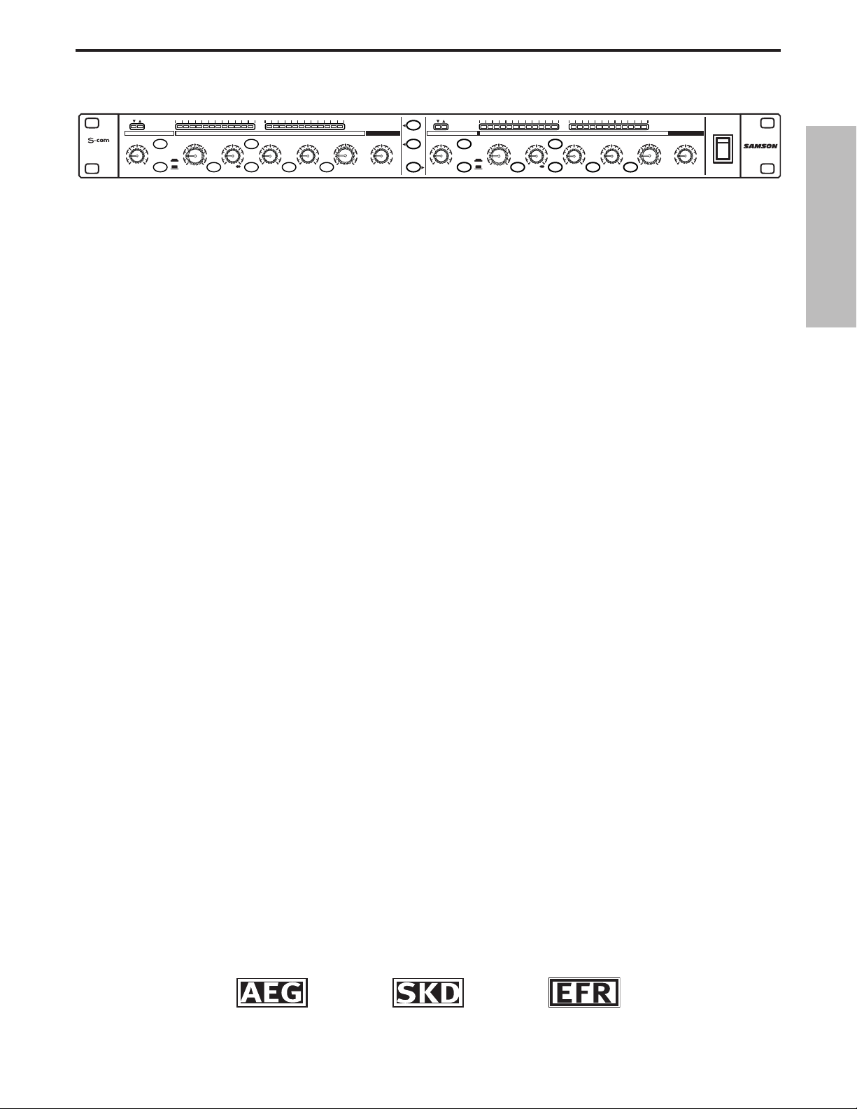
• SKD (Smart Knee Detector) switches from soft to hard knee based on the level of input signal.
• AEG (Automatic Envelope Generator) mode constantly adjusts the Compressor’s Attack and Release
times based on input signal. Manual adjustment of Attack and Release time is also facilitated.
• 12 Segment LED Input/Output Meter, plus 12 Segment LED Gain Reduction Meter.
• External Keying with Key Listen Switch available on front panel.
• Adjustable Enhancer to restore high-end loss resulting from heavy gain reduction.
• Expander/Gate with variable Threshold control and switchable Fast and Slow Release time.
• Gate function can be switched from hard Off to Light Downward Expander.
• Gate Open and Closed LED's.
• Spectra circuit enabling mid-high frequency contour for removing sibilance.
• Advanced circuit design, utilizing low noise operational amplifiers and high quality VCAs.
• Stereo Link Switch.
• Servo balanced inputs and outputs on XLR and 1/4” connectors.
• Switchable +4 and –10 operating levels.
• High quality 41 position detent pots and backlit switches.
• The stylish bead blasted electric blue anodized front-panel is as easy to read as it is to look at.
• Three-year extended warranty.
ENGLISH
Auto Envelope
GENERATOR
Smart Knee
DETECTOR
Enhanced
Frequency
RECOVERY
STEREO
COMPRESSOR
GAIN REDUCTION dB INPUT / OUTPUT LEVEL dB
30 24 2127 18 15 9 612 4 2 1 -30 -18 -12-24 -6 -3 +3 +60 +9 +12 +18
THRESHOLDTRIGGER RATIO ATTACK RELEASE OUTPUT ENHANCER
-10
10
GATE KEY
-30
FAST
+20-40
SLOW
dB
RELEASE SPECTRA KEY AUTO I/O METER
OFF +10
20
050
dB
COMPRESSOR / LIMITEREXPANDER/GATE
4:1
50
LISTEN
62
+10
.3 300
1
dB
mSec
OFF 10
STEREO LINK
IN/OUT 1
IN/OUT 2
20
GATE
GATE KEY
050
OFF +10
dB
RELEASE
5
73
0
1
20015
3.15
-10
.05 5
Sec
+10
+20-20
dB
GAIN REDUCTION dB INPUT / OUTPUT LEVEL dB
30 24 2127 18 15 9 612 4 2 1 -30 -18 -12-24 -6 -3 +3 +60 +9 +12+18
THRESHOLDTRIGGER RATIO ATTACK RELEASE OUTPUT ENHANCER
-10
10
-30
FAST
+20-40
SLOW
dB
COMPRESSOR / LIMITEREXPANDER/GATE
4:1
50
LISTEN
62
+10
SPECTRA KEY AUTO I/O METER
.3 300
1
dB
1
20015
3.15
.05 5
mSec
Sec
Sec
0
-10
+10
+20-20
dB
CH 2
CH 2CH 1
OFF 10
POWER
5
73
6
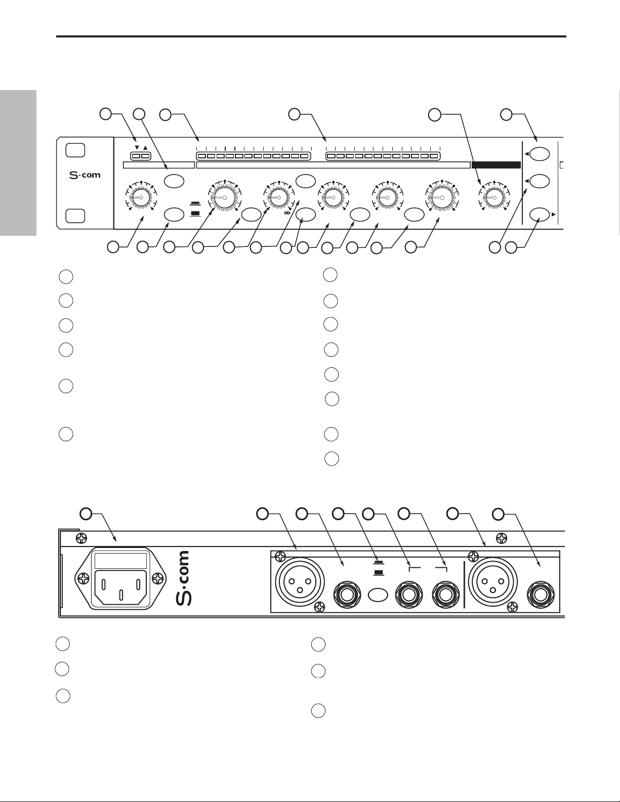
Controls and Functions
A AC INLET - IEC standard AC Power cable
Connector.
B CHANNEL 2 XLR INPUT - XLR Balanced line
input.
C CHANNEL 2 1/4”TRS INPUT - 1/4” TRS
Balanced line input.
D OPERATING LEVEL SWITCH - Switches the oper-
ating level from -10dB to +4dB.
E CHANNEL 2 KEY INPUT - Input connection
allowing external control of the S•com plus’
Compressor detection circuit.
F CHANNEL 1 KEY OUTPUT - S• com plus’ detec-
tor circuit is sent here. Use the Key Output to
process the compressor’s detector through an
external effect like an equalizer.
1 GATE OPEN & CLOSED LED - Indicates when the
gate is open and closed
2 GATE SWITCH - Selects either Gate or Expander
mode.
3 GAIN REDUCTION METER - Displays the amount of
Gain Reduction when Compressor circuit is activated.
4 INPUT/OUTPUT METER - Displays the Input or
Output signal level based on the settings of the I/O
meter switch.
5 ENHANCE LEVEL- Used to set the level of the S•
com’s Enhanced Spectrum Recovery circuit restoring
the high end loss resulting from extreme Gain
Reduction.
6 STEREO LINK SWITCH- When engaged channel 2’s
functions are controlled by the settings on channel 1.
.
0
7 CHANNEL 2 CONTROLS - The same knob and
switch complement as channel 1 .
8 MAINS POWER SWITCH -
When turned on, acti-
vates the S•com plus.
9 RACK EARS - Used for mounting into a standard 19
inch rack.
10 TRIGGER- Controls the threshold level that the
Expander/Gate becomes active.
11 RELEASE SWITCH - Selects FAST or SLOW Release
Time for EXPANDER/GATE.
12 THRESHOLD - Used to set the minimum signal
level at which the Compressor circuit begins to
function.
13 SPECTRA SWITCH - Enables the S•com’s SPECTRA
circuit for high frequency contouring.
14 RATIO - Controls the amount of Gain Reduction in
proportion to the amount of signal over the selected threshold level.
D
OUTPUT
D
UT
UT
OUTPUT
CHANNEL 2
0
ENGLISH
REAR PANEL LAYOUT
FRONT PANEL LAYOUT
1
STEREO
COMPRESSOR
OFF +10
10
2
3
30 24 2127 18 15 9 612 4 2 1 -30 -18 -12-24 -6 -3 +3 +60 +9 +12 +18
20
GATE KEY
050
dB
11
FAST
SLOW
RELEASE SPECTRA KEY AUTO I/O METER
12
13
GAIN REDUCTION dB INPUT / OUTPUT LEVEL dB
THRESHOLDTRIGGER RATIO ATTACK RELEASE OUTPUT ENHANCER
10
-10
-30
+10
+20-40
dB
14
15
4
COMPRESSOR / LIMITEREXPANDER/GATE
4:1
LISTEN
62
1
dB
17
16
50
.3 300
mSec
18
20015
19
.05 5
20
Sec
CH 1
5
OFF 10
22
6
73
23
STEREO LINK
IN/OUT 1
IN/OUT 2
5
5
1
3.15
21
0
-10
+10
+20-20
dB
A
B
-1
F G
INP
H
C
D
BALANCE
INP
E
BALANCE
7
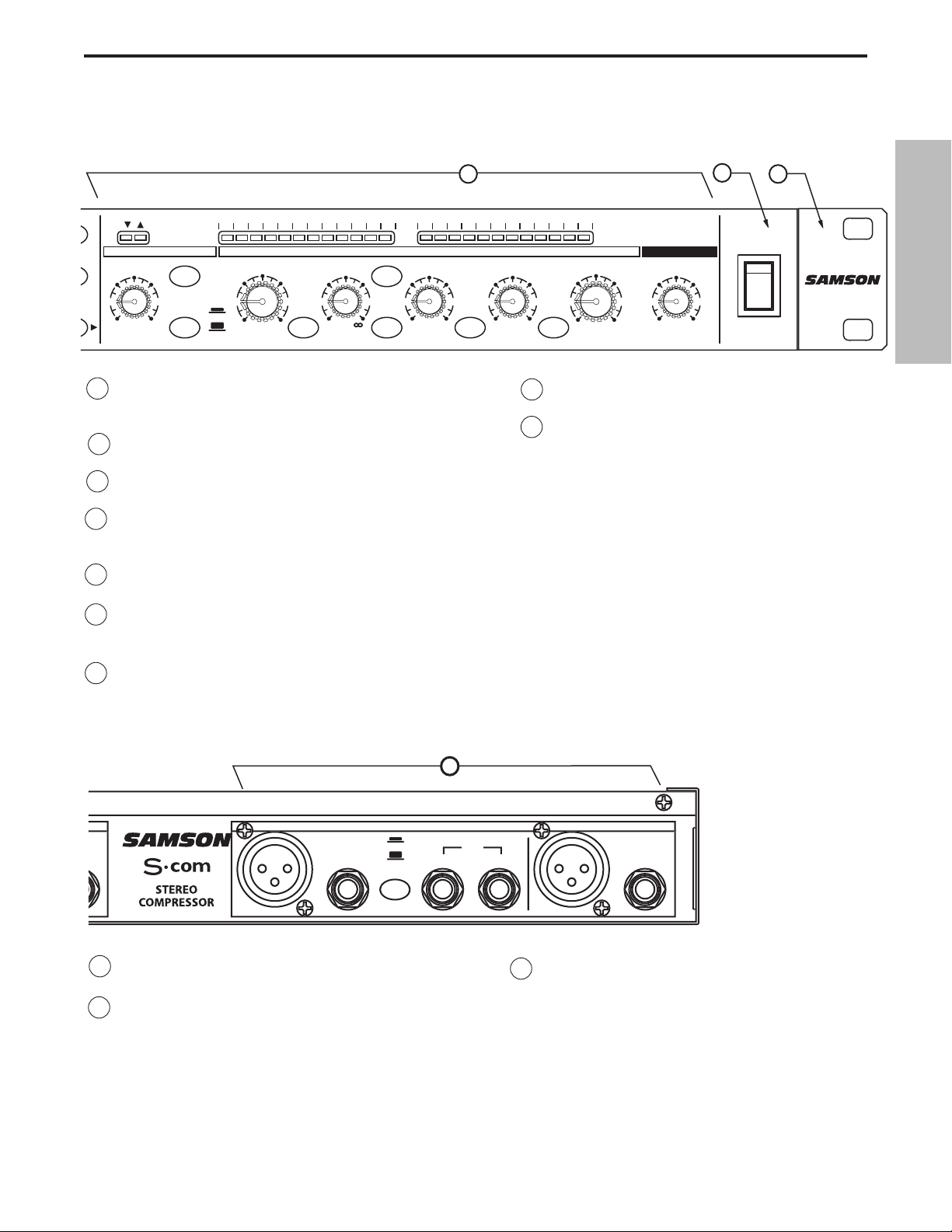
Controls and Functions
G CHANNEL 2 XLR OUTPUT - XLR Balanced line out-
put.
H CHANNEL 2 1/4”TRS OUTPUT - 1/4” TRS
Balanced line output.
I CHANNEL 1 - Same inputs and outputs as
Channel 1.
15 KEY LISTEN SWITCH - When engaged, the signal pres-
ent at the KEY INPUT is sent directly to the channel output.
16 KEY SWITCH- Selects the key input so that an external
signal may trigger the compressor.
17 ATTACK - Adjusts the amount of time the compressor
takes to reach full gain reduction.
18 AUTO - Activates S •com plus’ AEG (Auto Envelope
Generator) which dynamically adjusts the attack and
release time based on signal content.
19 RELEASE - Adjusts the length of time the compressor
takes to return the signal to it’s original level.
20 INPUT/ OUTPUT METER SELECT SWITCH - Selects
either Input or Output level to be displayed on the
Input/Output Meter.
21 LEVEL - Controls the amount of Output level.
22 CHANNEL 1 IN/OUT SWITCH- Activates
S•com Channel 1.
23 CHANNEL 2 IN/OUT SWITCH- Activates
S•com Channel 2.
D
D
OUTPUT
D
UT
UT
OUTPUT
C
1
0
ENGLISH
GAIN REDUCTION dB INPUT / OUTPUT LEVEL dB
THRESHOLDTRIGGER RATIO ATTACK RELEASE OUTPUT ENHANCER
-10
10
-30
+10
+20-40
dB
SPECTRA KEY AUTO I/O METER
COMPRESSOR / LIMITEREXPANDER/GATE
4:1
LISTEN
62
1
dB
50
.3 300
mSec
LINK
1
2
20
OFF +10
dB
30 24 2127 18 15 9 612 4 2 1 -30 -18 -12-24 -6 -3 +3 +60 +9 +12 +18
GATE KEY
GATE
050
RELEASE
FAST
SLOW
7
8
9
POWER
CH 2
CH 2
1
20015
.05 5
Sec
Sec
3.15
0
-10
+10
+20-20
dB
5
OFF 10
POWER
73
I
HANNEL
E
BALANCE
INP
-1
INP
BALANCE
8
Operating The S•com
Whether you are an experienced audio engineer, just starting out, or you just want to experiment, follow the
steps below to get going. Further sections in this manual will cover basic dynamics and the associated parameters, system set-ups and applications for using dynamics processing in recording and live sound applications.
SETTING UP THE S•com
• Connect one or both sets of inputs and outputs to the designated connectors on the rear panel.
• Set the controls to the following positions:
In this configuration, the S•com is simply passing audio at unity gain with no dynamics processing. It is a good
idea to check your gain structure at this point. Use the Input/Output meter to match the level.
Send a signal to either or both of the S•com’s inputs and outputs.
• Press the METER switch to see that the input and output levels are matched.
COMPRESSING A SIGNAL
S•com's Compressor section can be used for a variety of gain management tasks including printing signals to a
multi-track recorder, as a mix-down effect, mastering, and for increasing the loudness of a live PA system. To
begin compressing your signal, follow the steps below:
• Follow the section above, “SETTING UP THE S•com” for normalizing the controls.
• Press the CHANNEL IN switch (located in the middle of the unit) to the IN position.
• Press in the AUTO switch (located in-between ATTACK and RELEASE).
• Adjust the Ratio to 2:1.
EXPANDER/GATE TRIGGER – OFF
GATE SWITCH – OUT
FAST RELEASE – OUT
COMPRESSOR THRESHOLD – +20dBu (fully clockwise)
SPECTRA - OUT
RATIO – 1:1
KEY SWITCH - OUT
ATTACK – 0.3 (fully counter-clockwise)
AUTO SWITCH- OUT
RELEASE -5 (fully clockwise)
METER SWITCH – IN
OUTPUT LEVEL – O dBu
ENHANCER - OFF (fully counter-clockwise)
STEREO LINK SWITCH – OUT
CHANNEL 1 ENGAGE – OUT
ENGLISH
STEREO
COMPRESSOR
20
OFF +10
dB
30 24 2127 18 15 9 612 4 2 1 -30 -18 -12-24 -6 -3 +3 +60 +9 +12 +18
GATE KEY
050
FAST
SLOW
RELEASE SPECTRA KEY AUTO I/O METER
GAIN REDUCTION dB INPUT / OUTPUT LEVEL dB
THRESHOLDTRIGGER RATIO ATTACK RELEASE OUTPUT ENHANCER
-10
10
-30
+10
+20-40
dB
COMPRESSOR / LIMITEREXPANDER/GATE
-10
0
+10
+20-20
dB
4:1
LISTEN
62
1
dB
50
.3 300
mSec
1
20015
.05 5
Sec
3.15
CH 1
OFF 10
STEREO LINK
5
IN/OUT 1
73
IN/OUT 2
9
Operating The S•com
• Now gradually turn down the THRESHOLD level and
listen for the compression. For a visual representation,
the amount of compression is indicated on the GAIN
REDUCTION meter.
• Press out the AUTO button to experiment with manually
controlled ATTACK and RELEASE times.
OT
S
5
T
GATING A SIGNAL
Unwanted noises, buzzes and hisses can be easily removed by using S•com’ s GATE. The idea is to have the
Gate open only when your desired signal is playing and to mute off (Gate closed) the unwanted noise, buzz and
hiss. To Gate your signal, do the following:
• Follow the section above,” SETTING UP THE S•com” for normalizing the controls.
• To engage the Gate, make sure that the EXPANDER/GATE switch is pressed in.
0
3
• Press the RELEASE switch to the IN position to select
FAST release time.
• Now increase the THRESHOLD level and listen as the
signal begins to gate. For a visual representation of the
gate opening and closing, look at the GATE
OPEN/CLOSED LED’s located above the
EXPANDER/GATE TRIGGER control.
USING THE DOWNWARD EXPANDER
You can set the S•com's Gate section to work as a DOWNWARD EXPANDER to lower the volume of a signal.
Try the simple steps below:
• Follow the section above, “SETTING UP THE S•com” for normalizing the controls.
• To engage the EXPANDER, make sure that the EXPANDER/GATE button is switched to the OUT posi-
tion.
• Press the RELEASE switch out to select a SLOW RELEASE.
• Now increase the TRIGGER level and listen as the signal begins to get softer.
ENGLISH
30 24 2127 18 15 9 612 4 2 1 -3
E
E KEY
-30
FAST
SLOW
SE SPECTRA KEY
GAIN REDUCTION dB
THRESHOLD RATIO AT
-10
10
+10
dB
+20-40
1
4:1
dB
COMPRESS
LISTEN
62
15
.3
m
3
STEREO
COMPRESSOR
EXPANDER/GATE
TRIGGER
20
GATE
050
OFF +10
dB
RELEASE
-
FAST
SLOW

10
Operating The S•com
USING THE ENHANCER
The S•com’s ENHANCER switch can be engaged to activate the EFR (Enhanced Frequency Recovery) circuit.
By engaging the ENHANCER, the S•com EFR restores the high frequency content that can be lost when high
gain reduction is applied. The S•com EFR achieves this by adding back the high-end of the original signal in an
amount that is equal to the amount of gain reduction.
• Follow the section above, “SETTING UP THE S•com” for normalizing the controls and run a signal such
as a CD through the S•com plus.
• Press the CHANNEL IN switch (located in the middle of the
unit) to the IN position.
• Press in the AUTO switch (located in-between ATTACK and
RELEASE).
• Adjust the Ratio to 6 - 8:1.
• Gradually turn up the ENHANCER and listen to how the
high end is restored.
USING THE SPECTRA
The S•com’s SPECTRA is a powerful tool for removing annoying problems like heavy sibilance on vocal tracks
or bright cymbals. To listen to the SPECTRA try the following:
• Follow the section above, “SETTING UP THE S•com” for nor-
malizing the controls.
• Press the CHANNEL IN switch (located in the middle of the
unit) to the IN position.
• Run a signal with extra sibilance through the S•com.
• To engage the SPECTRA, make sure that the SPECTRA
switch is pressed in.
• Now listen how S•com’s Spectra reduces the sibilance.
E
5
A
1
E
ENGLISH
30 24 2127 18 15 9 612 4 2 1
GAIN REDUCTION dB
THRESHOLD RATIO
-10
10
-30
FAST
SLOW
+10
+20-40
dB
SPECTRA KEY
COMPR
4:1
KEY
LISTEN
62
1
1
dB
+10
CH 1
ENHANCER
5
OFF 10
73
STEREO LINK
IN/OUT 1
IN/OUT 2
50
EXP
TRIGG
20
OFF +
dB

11
Dynamics Processing 101
To begin to understand dynamics processing, we must first understand what dynamics are. Dynamics, or the
dynamic range of a signal or audio device, is the amount of level between the softest and loudest possible output. Dynamics processing is applied to a signal to manage the changes in level. Various types of processing
units are available to control dynamics including Noise Gates, Expanders, Compressors, Limiters and DeEssers. All of these processes have a unique effect on a signal, but one common element they share is that in
one way or another they control gain. Some dynamics processors control gain in a subtle way by slightly reducing how soft and loud a signal is, while others make drastic changes in gain like reducing the signal until it’s off.
Applications for dynamics processing can be categorized by two distinct groups; first, to treat a signal that has
an unpredictable dynamic range and make it predictable, and second, to create a "sound" by squeezing out the
dynamic range. Whether used for a live sound application, recording, mixing or mastering, dynamic processors
like the S•com are valuable tools for controlling gain. The following is a basic overview of dynamics processing
and how it is used to improve the quality of recorded and live sound.
COMPRESSOR
A good compressor is one of the most useful tools in live sound and recording. Compressors are used to control
the dynamic range of a signal, which offers a variety of benefits including leveling a signal that’s being recorded,
having an instrument sit in the mix, and increasing the loudness of a sound system to name a few. Drastic
amounts of compression will also result in an effect that becomes more of a sound, than just controlling gain. To
understand how a compressor works, it is necessary to become familiar with the basic parameters which include
threshold, ratio, attack time, and release time.
Threshold
Threshold is the level that once the signal exceeds, gain reduction is applied. The normal range of adjustment for
the threshold level is –40 to +20 dBu. If the threshold level is set above the highest level of the signal being sent
to the compressors, the gain reduction is never triggered. Therefore, the compressor is virtually by-passed. If
the threshold level is set very low so that any signal will trigger gain reduction, the compressor is working as an
automatic leveler.
Ratio
The ratio control is used to set the proportion of gain reduction in relationship to the input signal. For example if
the ratio is set to 2:1 and the signal crosses above the threshold level, an increase in level of 2 dB will produce a
1 dB increase in level at the output. A ratio setting of ∞ to 1 means that an infinite amount of input signal is
needed to raise the output level by 1 dB. This means that the output level stays constant even when the input
crosses over the threshold level.
Attack Time
Attack time is the amount of time that a compressor takes to effect the gain reduction after the signal rises above
the threshold level. A well-designed compressor has adjustable attack times ranging from 300 µs (microseconds) to 300 ms (milliseconds). A good compressor will sound smooth as it begins to control the gain regardless
of the attack time.
Release Time
The release time is set to control how long the compressor takes to return the input signal back to its original
level once the signal falls below the threshold level. The acceptable range for release time is from 50µs to 5 seconds. In normal use, faster release times are used for spoken word and longer release times are generally better
for instrumental music.
Auto Attack and Release
Today, sophisticated compressors often incorporate a dynamic or Auto Attack and Release mode. The S•com’s
AEG (Auto Envelope Generator) is such a mode which when engaged, automatically adjusts the attack and
release time based on the dynamically changing input signal.
ENGLISH

12
Dynamics Processing 101 - Continued
Soft-Knee / Hard-Knee
In order to prevent harsh, unnatural envelopes on compressed signals sophisticated dynamics processors like
the S•com feature an SKD (Smart Knee Detector) or automatic knee circuit. The Smart Knee Detector automatically switches from Soft-Knee when the signal is less than 10 dB over Threshold, to Hard-Knee when the signal
is 10db above Threshold. In Soft-Knee mode, there is a gradual effect on gain change, which begins as the signal approaches the Threshold level. In Hard-Knee mode, gain reduction is linear based on the Threshold and
Ratio controls. Any signal that falls below the Threshold level will be unprocessed.
Noise Gates
Noise gates are used to remove unwanted noise and/or bleed from recorded tracks in the studio or from open
microphones in live sound systems. Noise gates can also be used as a sound effect, most commonly to chop
the end of a reverb let’s say on a snare drum so that the entire snare sound ends just before the beat. The basic
principle of a noise gate is to work as an automatic mute switch. Mute off (Gate Open) when the desired signal
is present and mute on (Gate Closed) when the desired signal is not present. In order to get the gate to work
predictably, it is necessary to set a threshold, or trigger level that will determine when the gate will open. If the
signal is below the trigger the gate will remain closed. When the signal is above the trigger, the gate will trigger
open allowing the desired signal to pass and be heard. Noise gates often have other adjustable controls like
attack, hold, range and release. Many noise gates like the S•com use sophisticated circuits to control some of
these parameters automatically.
Downward Expander
The purpose of a well-designed Downward Expander is to increase the perceived dynamic range of a system.
This is accomplished by decreasing the gain during the softer sections, thereby lowering the relative noise floor.
When the signal level is below the desired trigger level, the expander lowers the overall gain by the selected
amount.
Stereo Link Mode
The S•com can be configured from dual-mono operation to stereo by using the Stereo Link switch. In Stereo
Link mode, Channel 2 functions are controlled by the settings of Channel 1 with the exception of IN/OUT and
KEY.
Side Chain / External Key
The S•com features a side-chain or external Key function. The external Key function is used to externally
process the compressor’s detector circuit. There are many useful applications for processing the detector circuit
including Equalizing for frequency dependent compression, De-Essing - the use of EQ to remove sibilance, and
externally keying off a vocal track for Ducking effects to name a few. Selecting the Key function on S•com’s front
panel, interrupts the compressors detector path and routes it to the Key Output jack.The Key Input jack receives
the externally processed signal, which will now control the compressor’s detector.
ENGLISH

13
Applications
Using the Expander/Gate to Remove Hiss and Noise
The S•com is an extremely useful tool in reducing the level of unwanted noises. By using the Expander/Gate you
can effectively fade the noise into the noise floor or abruptly turn the unwanted signal completely off.
Let’s say you want to reduce the bleed or cross talk that occurs when different instruments are recorded in close
proximity to each other. You have recorded an acoustic guitar simultaneously in the same room as with some
other acoustic instruments. The problem is that you hear a lot of the other instruments playing when the acoustic
guitar is silent. This can cause phasing and comb filtering problems due to microphone placement, so having the
bleeding signal drop into the noise floor is desirable.To do this, set the S•com to Expander mode with the
Release switch set to Slow and adjust the Threshold so that the acoustic guitar signal is well above the threshold
level. When the signal from the acoustic guitar track falls below the threshold level, the signal subtly fades into
the noise floor.
Now let’s say you’re attempting to remove the pick-up noise and hum from a guitar track that was recorded
through a loud amplifier. The hum and noise is most noticeable in-between the rhythm of the performance, so
you want to have the gate close during the silent parts and open during the musical passages. To do this, set the
S•com to Gate mode and adjust the Trigger level so that the gate is open just during the musical guitar parts,
and so that the gate is closed during the silent passages so that the hum and noise is muted.
Gating Drums
Using noise gates on drums is particularly useful in recording and in live sound. When a drum kit is set up with
individual microphones on each drum in a live PA system, there’s potential for great sound. However, there are
several gain management problems that can occur. Several microphones like the ones on the tom-toms, will
only be used occasionally and until the time that the tom-tom is actually played, its microphone is merely picking
up unwanted sound from other instruments on stage. This adds a lot of unwanted mush in the mix and also
adds to feedback problems. Use the S•com to gate the signal of the tom-tom by selecting Gate with the
Expander/Gate switch. Now adjust the Trigger control so that the gate opens only when the tom-tom is played,
and at the same time, so that the gate is closed even when the adjacent tom-tom is played. This same technique is useful on drums that have been recorded on individual tracks. By using the Gate to mute the bleed of
the other drums ,you can effectively reduce the comb filtering produced by phase cancellation due to microphone proximity.
Gating Longer Sounds
When using a noise-gate on sound with a longer decay like piano, it is usually necessary to use a longer release
time. Run the piano signal through the S•com and set the Expander/Gate Release switch to Slow. Adjust the
Trigger level on sustained passages to get the best results. Be sure to listen for the natural decay of the instru-
ment and allow the gate to remain open until just after end of the decay.
ENGLISH

Leveling a Vocal Track
When recording a vocal track, the vocalist may change the distance between them and the microphone, or they
may naturally have a lot of dynamic range in their performance. In either case, the sound engineer must decide
how much compression should be used to balance the natural performance and printing a good level to tape or
disk. Set up the S•com with a medium attack and release time and a ratio of 4:1. You can also use the Auto
button to engage the AEG (Auto Envelope Generator) for automatic attack and release. Now adjust the
Threshold level so that the Gain Reduction meters show 6 to 10 dB of gain reduction. Adjust the Ratio control if
necessary.
Leveling a Guitar or Bass
Guitar and especially bass guitar can have a lot of level change between strings and even frets on the fingerboard. Using compression when recording guitars and bass will even out these differences. Set up the compressor section of the S•com with a medium attack and release time and a ratio of 4:1. You can also use the
Auto button to engage the AEG (Auto Envelope Generator) for automatic attack and release. Now adjust the
Threshold level so that the Gain Reduction meters show 10 to 12 dB of gain reduction. You’ll notice that the each
note is at the same loudness and the overall sustain is increased.
Compressing Drums
Adding compression on drums can make a boomy kick drum tighten up, almost as if you were tightening the
head of a drum. Set the S•com to a fairly quick attack time and use a ratio of 6:1. Set the Threshold so that the
Gain Reduction meter reads 12 to 15 dB. Adjust the Ratio control if necessary. You can use the same basic set
up on snare and toms as well.
Getting a Track to Sit in the Mix
By using a heavy amount of compression you can get the effect of the vocal suspending in the mix. While this
may be a bit radical for some, the effect can be dramatic especially if the vocal is mixed without any reverb or
delay. Set up the compressor section of the S•com with a medium attack and release time and a ratio of 6:1.
You can also use the Auto button to engage the AEG (Auto Envelope Generator) for automatic attack and
release. Now adjust the Threshold level to so that the Gain Reduction meters show 21 to 24 dB of gain reduc-
tion.
Speaker Protection
There are several ways to use a compressor to protect a speaker system and many considerations can be made
including whether the speaker system is crossed-over actively or passively.
If the speaker system is stereo using a passive crossover, then the line output of the mixer or equalizer is run
directly into the S•com inputs. The S•com should be last in the chain before the power amps with its outputs
feeding the inputs of the amp. Now set the S•com to Stereo Link mode and use the Auto button to engage the
AEG (Auto Envelope Generator) for automatic attack and release. Adjust the Threshold and Ratio so that the
system’s entire dynamic range is under control.
When using an active crossover, multiple compressors can be used to compress each section of the PA. For
example, if the PA is using an active crossover to run a four-way mono system, two S•coms’ can be used for four
band compression. By compressing each output of the crossover, you can maximize the output level while minimizing the gain to sensitive speakers like the mid-range. Run the low and low-mid frequencies into two channels
of the first S•com and the high-mid and high frequencies into channel one and two of the second S•com.
Applications
14
ENGLISH

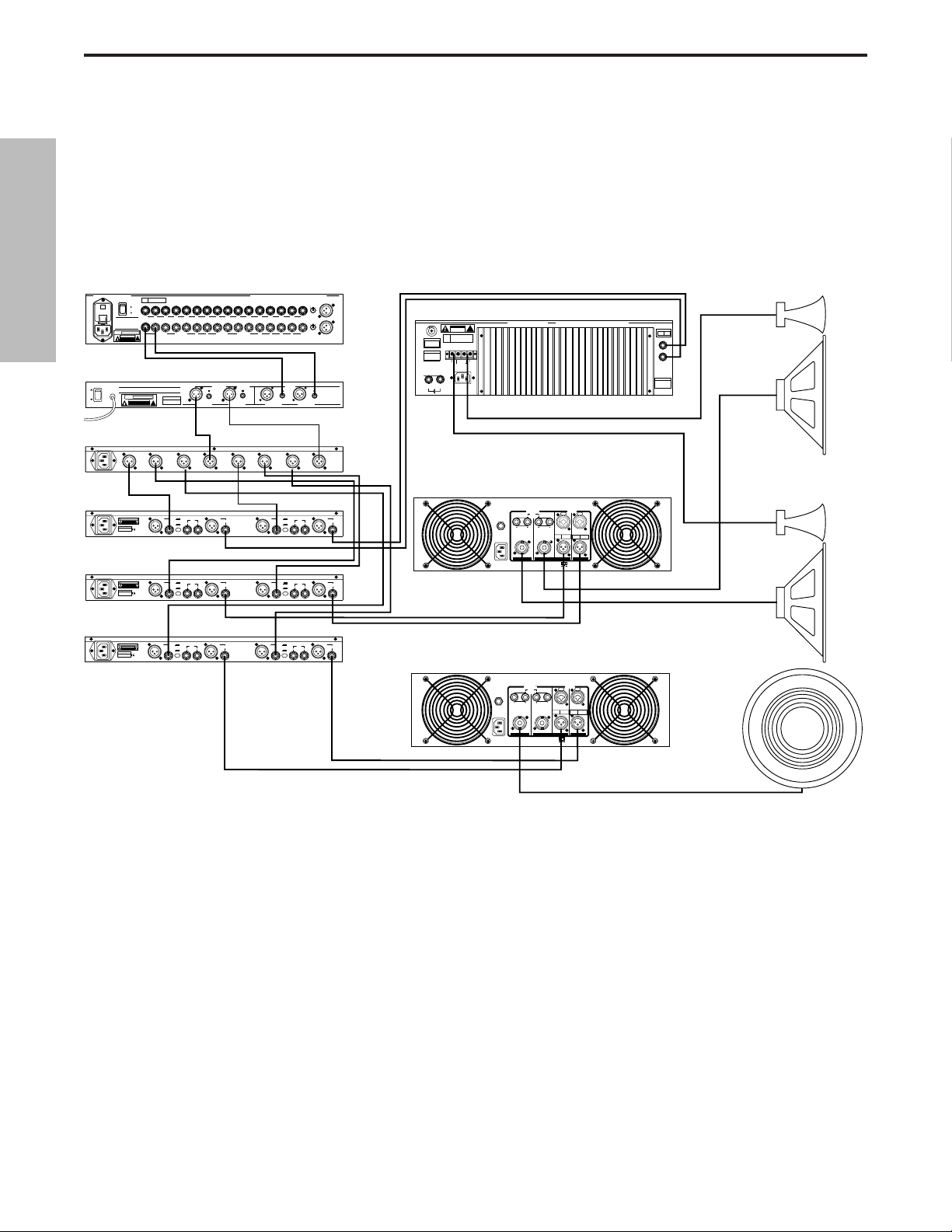
S•com System Set-Ups
LIVE SOUND SYSTEM WITH STEREO COMPRESSION
In this example, the S•com is inserted after the mixer and before the graphic equalizer,
thereby compressing the full range signal from the mixer.
15
ENGLISH
PL1602 Mixer
PL 1602
16 CHANNEL LINE MIXER
S / N
POWER
110
ON
OFF
AVIS:
RISQUE DE CHOC ELECTRIQUE
NE PAS OUVRIR
DO NOT EXPOSE THIS EQUIPMENT
TO RAIN OR MOISTURE
POWER
120V - 60 Hz 35W
RATING
CAUTION
RISK OF ELECTRIC SHOCK
~115V(0.3A)
230V(0.15A)
50/60Hz 30W
S•Com
SERIAL NUMBER
MADE IN CHINA
_ mA SLOW BLOW FUSE FOR 115V
_ mA SLOW BLOW FUSE FOR 220V
E30 Dual 15 Band EQ
E30 2/3 OCTAVE STEREO 15 BAND GRAPHIC EQUALIZER
AVIS: RISQUE DE CHOC ELECTRIQUE NE PAS OUVRIR. DO NOT EXPOSE
THIS EQUIPMENT TO RAIN OR MOISTURE.
ON
~AC INPUT
OFF
POWER
115V/230V 50/60Hz13W
BUS
INSERTS
BALANCED 600 +4db
!
MIXER LINKING
DO NOT OPEN
TIP + RING - SLEEVE GND
+4
BALANCED
CAUTION
INPUT
RISK OF ELECTRIC SHOCK
DO NOT OPEN.
POWER
RATING
RISK OF ELECTRIC SHOCK
120V - 60 Hz 20W
CAUTION
DO NOT OPEN
-10
INPUT OUTPUT
2
1
LEVEL
3
BALANCED <100Ω
0db UNITY GAIN
SERIAL NUMBER
!
S•3 Way
CH 2
HIGH
OUTPUT
2
2
2
1
1
CH 2
CH 2
MID
HIGH
3
3
3
OUTPUT
OUTPUT
MONO
MONO
HIGH-MID
HIGH
OUTPUT
OUTPUT
INPUTS BALANCED 10K‰ -30 to +4db TIP + RING - SLEEVE GND.
AUX
RETURNS
UNBALANCED 10K‰
CHANNEL 2
KEY
2
3
OUTPUTS
BALANCED
<100KΩ 0db
UNITY GAIN
CH 2
LOW
OUTPUT
2
1
1
CH 2
LOW
3
OUTPUT
2R
1L2R3L4RLRLR
1L
AUX SEND
UNBALANCED
2K‰ +4db
XLR
PIN 1 GND
BALANCED
PIN 2 HOT
OUTPUT
PIN 3 NEG
1
S com Plus
PHONE
TIP - POS
RING - NEG
SLEEVE - GND
BALANCED <100Ω
0db UNITY GAIN
CH 2
INPUT
2
1
CH 2
INPUT
3
SAMSON TECHNOLOGIES CORP., NEW YORK, U.S.A.
1L2R3L4R5L6R7L8R9L10R11L12R13L14R15L16R
6R 5L 4R 3L 2R 1L
INSERTS TIP RETURN RING SEND
CHANNEL 1
+4
KEY
BALANCED
INPUT
INPUT
-10
OUTPUT
2
1
LEVEL
3
INPUTS
BALANCED
0db UNITY GAIN
BALANCED
BALANCED
10KΩ
<100KΩ 0db
UNITY GAIN
CH 1
HIGH
OUTPUT
CH 1
HIGH
OUTPUT
CHANNEL ACHANNEL BCHANNEL ACHANNEL B
CH 1
LOW
OUTPUT
2
2
1
1
CH 1
CH 1
LOW
MID
3
3
OUTPUT
OUTPUT
MONO
MONO
LOW
LOW-MID
OUTPUT
OUTPUT
MIC 1
-10
2
3
0
1
-40+4
TRIM
-10
2
3
0
1
-40+4
TRIM
MIC 3MAIN OUT
BALANCED
OUTPUT
2
1
3
BALANCED
0db UNITY GAIN
BALANCED
10KΩ
SAMSON
TECHNOLOGIES
CORP.,
NEW YORK, U.S.A.
Servo 550 Power Amp (High)
CAUTION
RISK OF ELECTRIC SHOCK
DO NOT OPEN
F
E
U
S
SERIAL
FUSE
NUMBER
FUSE RATING
12A/250V (115V)
6A/250V (230V)
USE CLASS 2 WIRING MAXIMUM LOAD IMPEDANCE 4Ω
CAUTION
HEATSINK MAY BE
HOT! DO NOT BLOCK
AIRFLOW OR OVERHEATING MAY OCCUR
TO PREVENT SHOCK DO
GROUND
+RIGHT
NOT OPEN. NO USER
SERVICABLE PARTS
INSIDE. REFER SERVICING
TO QUALIFIED SERVICE
OUTPUT 250W/4Ω
PERSONNEL. TO PREVENT
FIRE OR SHOCK HAZARD
DO NOT EXPOSE TO RAIN
OR MOISTURE.
RIGHT
~AC INPUT
LEFT
115V/230W, 50/60HZ
510W (115V)900W (230V)
SERVO 550 STUDIO AMPLIFIER
!
LEFT+
SAMSON TECHNOLOGIES CORP., HICKSVILLE, NEW YORK
BRIDGED
TIP RING SLEEVE
SLEEVE GND
MONO STEREO
LEFT
RIGHT
INPUTS
(BALANCED
10KΩ/0dBm0)
TIP +
RING -
S1500 Power Amp (Mid)
INPUT
MODE
CHANNEL
STEREO
1 INPUT
2 WAY
2
1
CHANNEL
STEREO
1 INPUT
3 WAY
3
MONO
MONO
INPUT
4 WAY
PUSH TO RESET
115V 60Hz, 920W
OUTPUT
20A/250V
(4Ω~8Ω) (4Ω~8Ω)
~AC INPUT
(4Ω~8Ω) (4Ω~8Ω)
CH 2 CH 1
BALANCED
0dBm
TIP=HOT
TRS
RING=COLD
BALANCED
SLEEVE=GND
CH 2 CH 1
BRIDGED PARALLEL
STEREO
BALANCED
0dBm
3=COLD
XLR
2=HOT
BALANCED
1=GND
Left High / Mid
Right High / Mid
S2000 Power Amp
(Bridged Mono Low)
INPUT
OUTPUT
PUSH TO RESET
25A/250V
115V 60Hz, 1100W
(4Ω~8Ω) (4Ω~8Ω)
~AC INPUT
(4Ω~8Ω) (4Ω~8Ω)
CH 2 CH 1
BALANCED
0dBm
TRS
BALANCED
CH 2 CH 1
BRIDGED PARALLEL
STEREO
BALANCED
0dBm
TIP=HOT
3=COLD
XLR
RING=COLD
2=HOT
BALANCED
SLEEVE=GND
1=GND
Mono
Sub
16
S•com System Set-Ups
LIVE SOUND SYSTEM WITH MULTIBAND COMPRESSION
In this example, three S•com’s are inserted after the mixer, equalizer and crossover, thereby
providing individual compression on the low, mid and high frequencies.
ENGLISH
PL1602 Mixer
PL 1602
16 CHANNEL LINE MIXER
S / N
POWER
110
ON
OFF
AVIS:
RISQUE DE CHOC ELECTRIQUE
NE PAS OUVRIR
DO NOT EXPOSE THIS EQUIPMENT
TO RAIN OR MOISTURE
POWER
120V - 60 Hz 35W
RATING
CAUTION
RISK OF ELECTRIC SHOCK
~115V(0.3A)
230V(0.15A)
50/60Hz 30W
E30 Dual 15 Band EQ
ON
OFF
POWER
S•3 Way
BALANCED 600 +4db
!
DO NOT OPEN
TIP + RING - SLEEVE GND
E30 2/3 OCTAVE STEREO 15 BAND GRAPHIC EQUALIZER
AVIS: RISQUE DE CHOC ELECTRIQUE NE PAS OUVRIR. DO NOT EXPOSE
THIS EQUIPMENT TO RAIN OR MOISTURE.
~AC INPUT
POWER
120V - 60 Hz 20W
RATING
CAUTION
RISK OF ELECTRIC SHOCK
!
DO NOT OPEN
115V/230V 50/60Hz13W
CH 2
HIGH
OUTPUT
2
2
1
CH 2
HIGH
3
OUTPUT
MONO
HIGH
OUTPUT
S•Com
CAUTION
RISK OF ELECTRIC SHOCK
DO NOT OPEN.
2
SERIAL NUMBER
MADE IN CHINA
_ mA SLOW BLOW FUSE FOR 115V
_ mA SLOW BLOW FUSE FOR 220V
S•Com
CAUTION
RISK OF ELECTRIC SHOCK
DO NOT OPEN.
2
SERIAL NUMBER
MADE IN CHINA
_ mA SLOW BLOW FUSE FOR 115V
_ mA SLOW BLOW FUSE FOR 220V
S•Com
CAUTION
RISK OF ELECTRIC SHOCK
DO NOT OPEN.
2
SERIAL NUMBER
MADE IN CHINA
_ mA SLOW BLOW FUSE FOR 115V
_ mA SLOW BLOW FUSE FOR 220V
Left High / Mid
Right High / Mid
Mono
Sub
2R
1L2R3L4RLRLR
AUX SEND
UNBALANCED
2KΩ +4db
OUTPUTS
BALANCED
<100KΩ 0db
UNITY GAIN
CH 2
INPUT
2
1
CH 2
INPUT
3
SAMSON TECHNOLOGIES CORP., NEW YORK, U.S.A.
6R 5L 4R 3L 2R 1L
1L
INSERTS TIP RETURN RING SEND
BALANCED <100Ω
0db UNITY GAIN
BALANCED
0db UNITY GAIN
BALANCED
<100KΩ 0db
UNITY GAIN
CH 1
HIGH
OUTPUT
2
2
1
1
CH 1
CH 1
MID
HIGH
3
3
OUTPUT
OUTPUT
MONO
LOW-MID
OUTPUT
INPUTS BALANCED 10KΩ -30 to +4db TIP + RING - SLEEVE GND.
AUX
BUS
RETURNS
INSERTS
MIXER LINKING
UNBALANCED 10KΩ
BALANCED <100Ω
0db UNITY GAIN
SERIAL NUMBER
CH 2
LOW
OUTPUT
2
1
1
CH 2
CH 2
LOW
MID
3
3
OUTPUT
OUTPUT
MONO
HIGH-MID
OUTPUT
MIC 1
-10
2
3
0
1
-40+4
TRIM
1L2R3L4R5L6R7L8R9L10R11L12R13L14R15L16R
-10
2
3
0
1
-40+4
TRIM
MIC 3MAIN OUT
INPUTS
BALANCED
0db UNITY GAIN
BALANCED
BALANCED
10KΩ
10KΩ
SAMSON
TECHNOLOGIES
CORP.,
NEW YORK, U.S.A.
CHANNEL ACHANNEL BCHANNEL ACHANNEL B
MODE
CHANNEL
CH 1
STEREO
1 INPUT
LOW
2 WAY
OUTPUT
2
2
1
1
CH 1
CHANNEL
STEREO
LOW
1 INPUT
3 WAY
3
3
OUTPUT
MONO
MONO
MONO
LOW
INPUT
4 WAY
OUTPUT
Servo 550 Power Amp (High)
CAUTION
RISK OF ELECTRIC SHOCK
DO NOT OPEN
F
E
U
S
SERIAL
FUSE
NUMBER
FUSE RATING
12A/250V (115V)
6A/250V (230V)
USE CLASS 2 WIRING MAXIMUM LOAD IMPEDANCE 4Ω
CAUTION
HEATSINK MAY BE
HOT! DO NOT BLOCK
AIRFLOW OR OVERHEATING MAY OCCUR
TO PREVENT SHOCK DO
GROUND
+RIGHT
NOT OPEN. NO USER
SERVICABLE PARTS
INSIDE. REFER SERVICING
TO QUALIFIED SERVICE
OUTPUT 250W/4Ω
PERSONNEL. TO PREVENT
FIRE OR SHOCK HAZARD
DO NOT EXPOSE TO RAIN
OR MOISTURE.
RIGHT
~AC INPUT
LEFT
115V/230W, 50/60HZ
510W (115V)900W (230V)
SERVO 550 STUDIO AMPLIFIER
!
LEFT+
SAMSON TECHNOLOGIES CORP., HICKSVILLE, NEW YORK
BRIDGED
TIP RING SLEEVE
MONO STEREO
LEFT
RIGHT
INPUTS
(BALANCED
10KΩ/0dBm0)
TIP +
RING SLEEVE GND
S1500 Power Amp (Mid)
INPUT
PUSH TO RESET
115V 60Hz, 1100W
PUSH TO RESET
~AC INPUT
115V 60Hz, 920W
25A/250V
~AC INPUT
OUTPUT
20A/250V
(4Ω~8Ω) (4Ω~8Ω)
(4Ω~8Ω) (4Ω~8Ω)
CH 2 CH 1
OUTPUT
(4Ω~8Ω) (4Ω~8Ω)
(4Ω~8Ω) (4Ω~8Ω)
CH 2 CH 1
BALANCED
TRS
BALANCED
BRIDGED PARALLEL
BALANCED
0dBm
TIP=HOT
TRS
RING=COLD
BALANCED
SLEEVE=GND
CH 2 CH 1
BRIDGED PARALLEL
STEREO
0dBm
TIP=HOT
RING=COLD
SLEEVE=GND
CH 2 CH 1
STEREO
INPUT
BALANCED
BALANCED
0dBm
3=COLD
XLR
2=HOT
BALANCED
1=GND
BALANCED
0dBm
3=COLD
XLR
2=HOT
1=GND
CHANNEL 2
+4
KEY
BALANCED
INPUT
-10
INPUT OUTPUT
1
LEVEL
3
CHANNEL 2
+4
KEY
BALANCED
INPUT
-10
INPUT OUTPUT
1
LEVEL
3
CHANNEL 2
+4
KEY
BALANCED
INPUT
-10
INPUT OUTPUT
1
LEVEL
3
XLR
PIN 1 GND
BALANCED
PIN 2 HOT
OUTPUT
PIN 3 NEG
2
1
S com
3
PHONE
TIP - POS
RING - NEG
SLEEVE - GND
XLR
PIN 1 GND
BALANCED
PIN 2 HOT
OUTPUT
PIN 3 NEG
2
1
S com
3
PHONE
TIP - POS
RING - NEG
SLEEVE - GND
XLR
PIN 1 GND
BALANCED
PIN 2 HOT
OUTPUT
PIN 3 NEG
2
1
S com
3
PHONE
TIP - POS
RING - NEG
SLEEVE - GND
CHANNEL 1
+4
KEY
BALANCED
INPUT
2
1
3
BALANCED
INPUT
2
1
3
BALANCED
INPUT
2
1
3
BALANCED
OUTPUT
INPUT
-10
OUTPUT
2
1
LEVEL
3
CHANNEL 1
+4
KEY
BALANCED
OUTPUT
INPUT
-10
OUTPUT
2
1
LEVEL
3
CHANNEL 1
+4
KEY
BALANCED
OUTPUT
INPUT
-10
OUTPUT
2
1
LEVEL
3
S2000 Power Amp
(Bridged Mono Low)
17
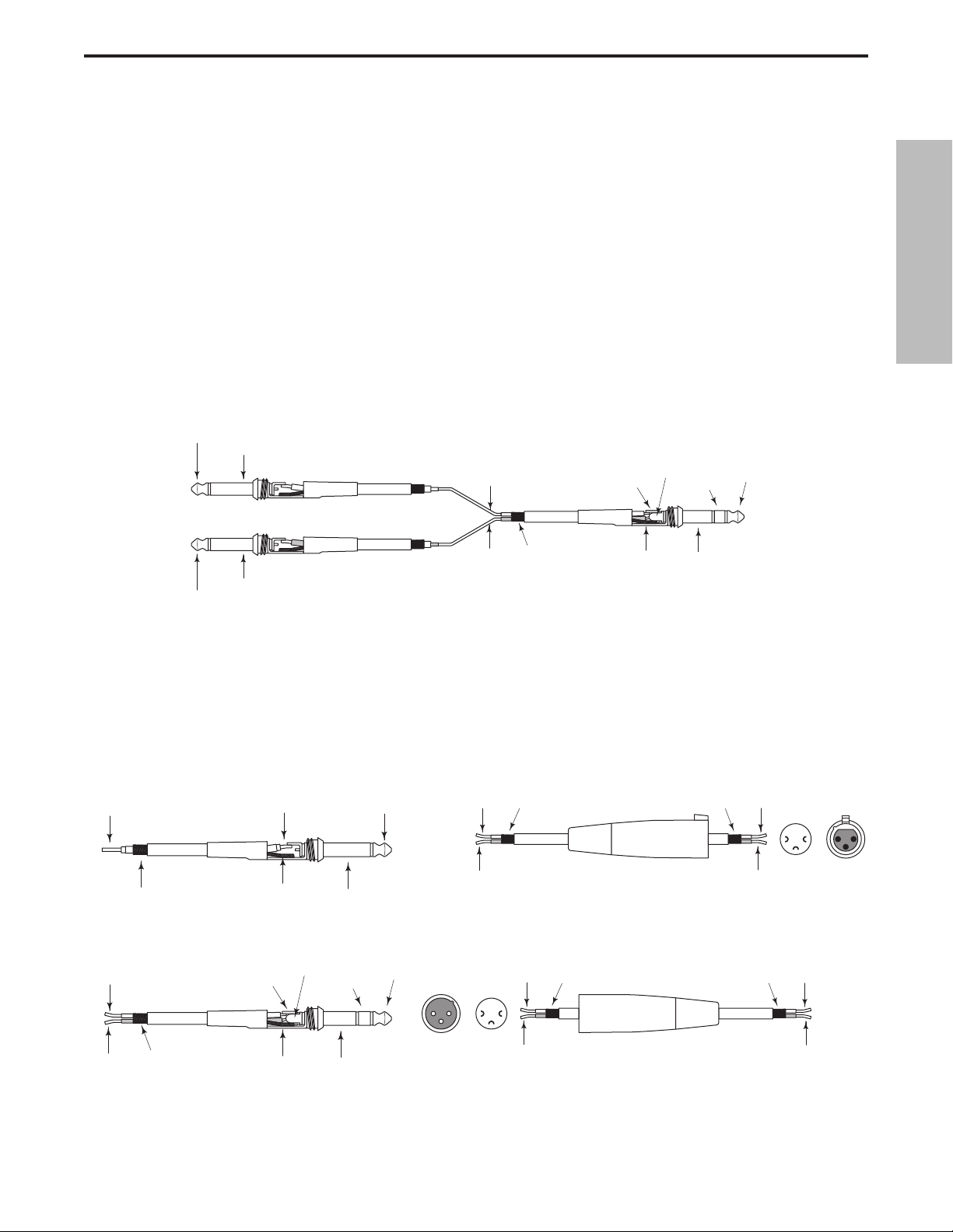
S•com Connections
Unbalanced 1/4”Connector
Insert Cable 1/4” male TRS connector to two male 1/4”
in send and return configuration.
XLR Balanced Wiring Guide
CONNECTING THE S•com
The are several ways to interface the S•com to support a variety of applications. The S•com features servo-balanced inputs and outputs, so connecting balanced and unbalanced signals is possible without any signal loss.
The S•com can be used on a single instrument by connecting to a channel’s insert points, or on an entire mix
"in-line" between a mixer’s outputs and a power amp or equalizer.
INSERT POINTS
Many mixers today provide channel and bus or group inserts. Insert points are input and output patch points
that interrupt the channel or bus signal so that external processors can be connected. Channel insert points are
ideal for connecting to when using the S•com to process a single channel like a vocal, bass or guitar. Bus
insert points are ideal for compressing groups of instruments like vocals, strings or drums. If you are connecting
to a channel’s insert points, you may have a single TRS jack for Send & Return. In this case, use an Insert "Y"
Cable that configured like the one in the wiring diagram below.
IN-LINE
In live sound operation the S•com can be installed in-line between a mixer and equalizer or power amplifier. For
these applications the S•com provides both 1/4" TRS connectors and XLR connectors to easily interface with
most any professional audio device. Follow the wiring examples below for your particular installation.
Balanced TRS 1/4” Connector
ENGLISH
Tip (send)
Sleeve (common)
Send (tip)
Send (tip)
Return (ring)
Ring (return)
Tip (send)
Return (ring)
Sleeve (common)
Tip (return)
Common
Common
Sleeve (common)
Signal
Ground
Ground
Tip (signal)Signal
Sleeve (ground)
Hot
Cold
Female XLR
Hot (2)
Common (1)Common
1
2
21
3
Solder Points End View
Cold (3)
3
Signal (tip)
Signal (ring)
Ground
Signal (ring)
Signal (tip)
Ground
Ring (signal)
Sleeve (ground)
Tip (signal)
2
12
3
End View Solder Points
1
3
Hot (2)
Common (1) Common
Cold (3)
Male XLR
Hot
Cold

18
Note de Ray Kennedy
Les compresseurs et limiteurs sont des outils fondamentaux pour l’enregistrement et le mixage.
Beaucoup ne réalisent pas à quel point ils sont essentiels. Pour moi, la compression est bien plus
qu’un simple processeur de dynamique. Chaque modèle possède son propre son et se révèle idéal
pour des applications bien spécifiques. C’est pourquoi je dispose d’un choix d’environ quarante compresseurs. L’apprentissage des spécificités de chaque compresseur et de ses réglages est un
procédé qui nécessite beaucoup d’expérimentations.
Les limiteurs de crêtes et les compresseurs conviennent généralement très bien pour optimiser le
niveau des bandes ou des disques sans ajouter trop de coloration sonore.En somme, il s’agit de supprimer les crêtes et d’accentuer les passages les plus faibles d’un signal en resserrant la plage
dynamique. Des temps d’attaque et de rétablissement élevés permettent d’obtenir un son plus trans-
parent. Personnellement, j’apprécie vraiment le son de la compression et je l’utilise parfois de manière
assez poussée. Selon le type d’appareil et de réglage, vous pouvez obtenir tellement de caractéris-
tiques sonores grâce à la compression, en ajoutant de l’ambiance, en durcissant, en adoucissant le
son ou en appliquant une correction... Mon réglage de compression préféré est de “suspendre” les
voix dans le mixage, sans réverbération et intimistes, comme si le chanteur se trouvait juste devant
vous, sans que le son soit trop fort. Steve Earl, mon partenaire, dit que la compression de sa voix
durant les enregistrements permet presque à l’auditeur de savoir ce qu’il a mangé au petit-déjeuner.
De bien des manières, la compression finit par remplacer la réverbération et, poussée à l’extrême,
elle ajoute toute l’ambiance nécessaire à un micro et fait ressortir le caractère profond de vos cordes
vocales.Sur un micro d’ambiance, vous pouvez modifier la perception de la taille de la pièce en faisant
durer le son en cours de déclin. De nouveau, un long temps d’attaque et un court temps de rétablissement offrent les meilleurs résultats car vous pouvez utiliser des réglages de seuil plus poussés.
La limitation et la compression du bus stéréo est aussi une excellente manière de souder les pistes
ce qui donne l’impression que les groupes ont un son plus dense. Cela permet également d’obtenir
un niveau supérieur avant saturation lors de la copie sur deux pistes analogiques, ainsi qu’une modulation accrue des formats numériques. Il est assez fréquent que j’applique trois limiteurs stéréo avant
d’en arriver au Mastering sur disque dur et d’en garder les parties définitives qui en seront extraites.
Souvent, le fait d’appliquer plusieurs compresseurs à un même signal permet d’obtenir des résultats
intéressants, qui ne peuvent être obtenus avec un seul compresseur. Bien entendu, il n’y a pas de
règles fixes, mais il est important de savoir que le traitement du son peut être réalisé de nombreuses
façons. Certains traitements sont entièrement à lampes, d’autres lampes et optique, uniquement
optiques, transistors FET, VCA pure classe A, classe A/B, numériques, et bien d’autres combinaisons
encore.
Aujourd’hui, nous pouvons enfin disposer de VCA de très haute qualité, pas trop chers et permettant
des traitements sonores sophistiqués et polyvalents, comme les appareils S-Class de Samson.
Ray Kennedy
Ray Kennedy est producteur, ingénieur du son et parolier. Il est
basé à Nashville où se trouve la société de production
Twang Trust, créée en partenariat par Ray et le chanteur/parolier Steve Earle. Twang Trust a réalisé les enregistrements
d’artistes de renom comme Steve Earle,
Art Garfunkel, Willie Nelson et Waylon Jennings, Farm Aid,
The Del McCoury Band, Nancy Griffith, Lucinda Williams,
David Alan Coe, Shaver, V-Roys et Rosie Flores.
FRANÇAIS
Caractéristiques du S•com
Le processeur de dynamique Samson S com utilise une technologie de pointe en matière de gestion du gain.
Voici quelques-unes de ses principales caractéristiques :
• Processeur de dynamique complet à deux canaux, avec compresseur/limiteur, expanseur/Noise Gate et
Enhancer.
• La fonction SKD (détecteur Smart Knee) permet de passer d’une courbe Soft Knee à Hard Knee, selon
le niveau d’entrée du signal.
• Le mode AEG (générateur d’enveloppe automatique) ajuste automatiquement les temps d’attaque et de
rétablissement du compresseur en fonction du signal d’entrée. Il est également possible d’effectuer un
réglage manuel des temps d’attaque et de rétablissement.
• Afficheur de niveau d’entrée/sortie 12 segments à LED et afficheur de réduction de gain 12 segments à LED.
• Possibilité de contrôle externe du circuit de commande avec commutateur Key en face avant.
• Enhancer réglable permettant de restaurer la perte des aigus résulant d’une réduction de gain massive.
• Expanseur/Noise Gate avec seuil de déclenchement variable et temps de rétablissement réglable (rapi-
de/lent).
• La fonction de Noise Gate peut être réglée de Off (désactivée) à une fonction d’expanseur léger.
• LED d’indication d’ouverture et de fermeture du Noise Gate.
• Circuit Spectra permettant un ciselage des médiums pour supprimer les sibilantes.
• Circuits haute technologie, utilisant des amplificateurs à faible bruit et des VCA de haute qualité.
• Fonction Stereo Link de couplage stéréo.
• Entrées et sorties à symétrie électronique sur connecteurs XLR et Jacks 6,35 mm.
• Niveau d’utilisation commutable +4 dBu/ -10 dBV.
• Potentiomètres crantés 41 positions de haute qualité et touches rétro-éclairées.
• L’aspect agréable de la façade stylée en acier anodisé bleu électrique facilite la lecture des réglages.
• Garantie de 3 ans.
19
FRANÇAIS
STEREO
COMPRESSOR
GAIN REDUCTION dB INPUT / OUTPUT LEVEL dB
30 24 2127 18 15 9 612 4 2 1 -30 -18 -12-24 -6 -3 +3 +60 +9 +12+18
THRESHOLDTRIGGER RATIO ATTACK RELEASE OUTPUT ENHANCER
-10
10
GATE KEY
-30
FAST
+20-40
SLOW
dB
RELEASE SPECTRA KEY AUTO I/O METER
OFF +10
20
050
dB
COMPRESSOR / LIMITEREXPANDER/GATE
4:1
50
LISTEN
62
+10
.3 300
1
dB
mSec
OFF 10
STEREO LINK
IN/OUT 1
IN/OUT 2
20
GATE
GATE KEY
050
OFF +10
dB
RELEASE
5
73
0
1
20015
3.15
-10
.05 5
Sec
+10
+20-20
dB
GAIN REDUCTION dB INPUT / OUTPUT LEVEL dB
30 24 2127 18 15 9 612 4 2 1 -30 -18 -12-24 -6 -3 +3 +60 +9 +12+18
THRESHOLDTRIGGER RATIO ATTACK RELEASE OUTPUT ENHANCER
-10
10
-30
FAST
+20-40
SLOW
dB
COMPRESSOR / LIMITEREXPANDER/GATE
4:1
50
LISTEN
62
+10
SPECTRA KEY AUTO I/O METER
.3 300
1
dB
1
20015
3.15
.05 5
mSec
Sec
Sec
0
-10
+10
+20-20
dB
CH 2
CH 2CH 1
OFF 10
POWER
5
73
 Loading...