

Page 1

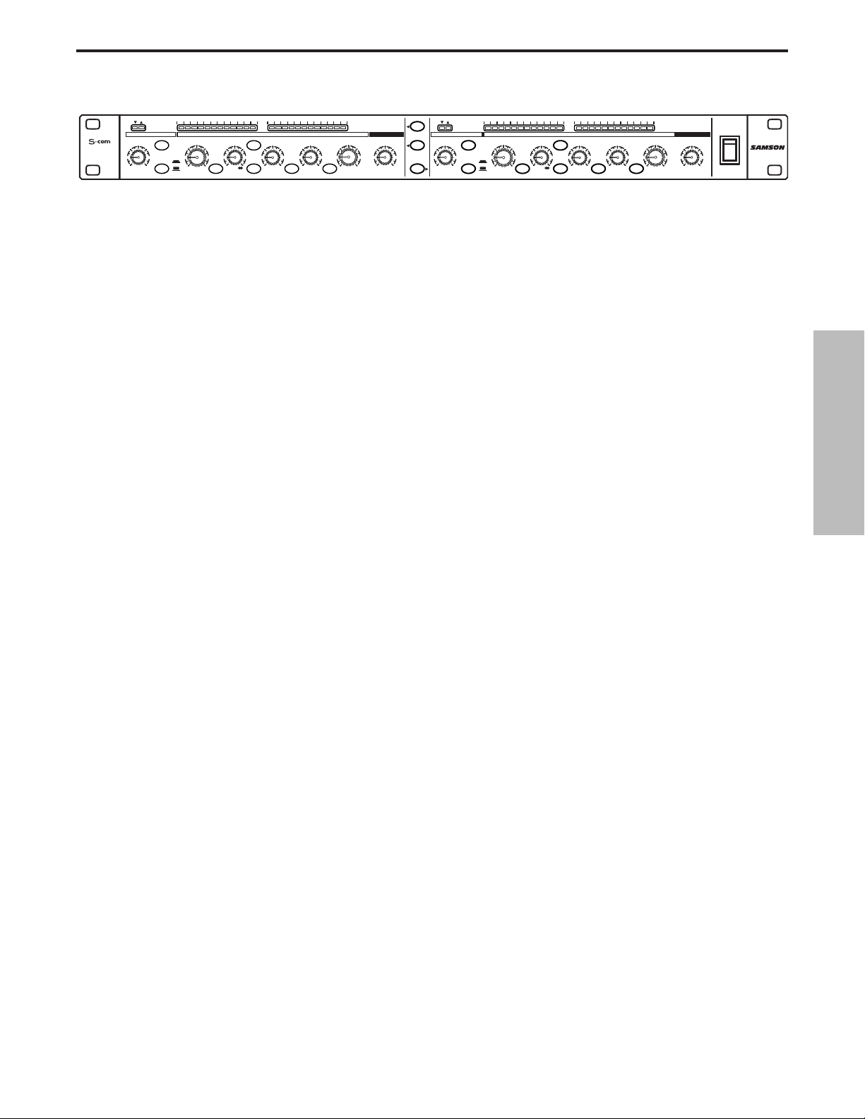
S Class Signal Processors
STEREO COMPRESSOR
STEREO
COMPRESSOR
GAIN REDUCTION dB INPUT / OUTPUT LEVEL dB
30 24 2127 18 15 9 612 4 2 1 -30 -18-12-24 -6 -3 +3 +60 +9 +12 +18
THRESHOLDTRIGGER RATIO ATTACK RELEASE OUTPUT ENHANCER
-10
10
GATE KEY
050
-30
FAST
SLOW
dB
RELEASE SPECTRA KEY AUTO I/O METER
OFF +10
20
dB
COMPRESSOR / LIMITEREXPANDER/GATE
4:1
50
LISTEN
62
+10
1
+20-40
.3 300
mSec
dB
GAIN REDUCTION dB INPUT / OUTPUT LEVEL dB
20015
.05 5
-10
+20-20
dB
Sec
0
1
3.15
STEREO LINK
5
IN/OUT 1
73
+10
OFF 10
IN/OUT 2
30 24 2127 18 15 9 612 4 2 1 -30 -18-12-24 -6 -3 +3 +60 +9 +12 +18
THRESHOLDTRIGGER RATIO ATTACK RELEASE OUTPUT ENHANCER
-10
10
20
GATE
GATE KEY
050
-30
FAST
OFF +10
SLOW
dB
RELEASE
4:1
+10
1
+20-40
dB
dB
SPECTRA KEY AUTO I/O METER
COMPRESSOR / LIMITEREXPANDER/GATE
50
LISTEN
62
20015
.3 300
mSec
.05 5
0
1
3.15
-10
+10
+20-20
dB
Sec
Sec
OFF 10
CH 2
CH 2CH 1
POWER
5
73
Page 2
1
Safety Instructions
Caution: To reduce the hazard of electrical
shock, do not remove cover or back.
No user serviceable parts inside. Please refer all
servicing to qualified personnel.
WARNING: To reduce the risk of fire or electric shock, do not expose this unit to rain or moisture.
The lightning flash with an arrowhead symbol within an equilateral triangle, is intended to alert the user to the
presence of uninsulated "dangerous voltage" within the products enclosure that may be of sufficient magnitude
to constitute a risk of electric shock to persons.
The exclamation point within an equilateral triangle is intended to alert the user to the presence of important
operating and maintenance (servicing) instructions in the literature accompanying the product.
Important Safety Instructions
1. Please read all instructions before operating the unit.
2. Keep these instructions for future reference.
3. Please heed all safety warnings.
4. Follow manufacturers instructions.
5. Do not use this unit near water or moisture.
6. Clean only with a damp cloth.
7. Do not block any of the ventilation openings. Install in accordance with the manufacturers instructions.
8. Do not install near any heat sources such as radiators, heat registers, stoves, or other apparatus
(including amplifiers) that produce heat.
9. Do not defeat the safety purpose of the polarized or grounding-type plug. A polarized plug has two
blades with one wider than the other. A grounding type plug has two blades and a third grounding
prong. The wide blade or third prong is provided for your safety. When the provided plug does not fit
your outlet, consult an electrician for replacement of the obsolete outlet.
10. Protect the power cord from being walked on and pinched particularly at plugs, convenience receptacles and at the point at which they exit from the unit.
11. Unplug this unit during lightning storms or when unused for long periods of time.
12. Refer all servicing to qualified personnel. Servicing is required when the unit has been damaged in
any way, such as power supply cord or plug damage, or if liquid has been spilled or objects have fallen into the unit, the unit has been exposed to rain or moisture, does not operate normally, or has
been dropped.
ENGLISH
FOR CONTINUED PROTECTION AGAINST RISK
OF FIRE, REPLACE ONLY WITH SAME TYPE FUSE
CAUTION
ATTENTION
UTILISER UN FUSIBLE DE
RECHANGE DE MÊME TYPE
WARNING
DO NOT EXPOSE THIS EQUIPMENT
TO RAIN OR MOISTURE
AVIS
RISQUE DE CHOC ELECTRONIQUE
NE PAS OUVRIR
RISK OF ELECTRIC SHOCK
DO NOT OPEN
Page 3

ENGLISH
Forward by Ray Kennedy 3
Introduction 4
S•com Features 5
Controls and Functions
Front Panel Layout 6-7
Rear Panel Layout 6-7
Operating the S•com
Setting Up the S•com 8
Compressing A Signal 8
Gating A Signal 9
Using The Expander 9
Using the Spectra 10
Using the Enhancer 10
Dynamics Processing 101 11-12
Applications 13-14
System Set-ups 15-16
S•com Connections 17
Specifications 60-61
Block Diagram 62
Copyright 2001, Samson Technologies Corp.
Printed May, 2001
Samson Technologies Corp.
575 Underhill Blvd.
P.O. Box 9031
Syosset, NY 11791-9031
Phone: 1-800-3-SAMSON (1-800-372-6766)
Fax: 516-364-3888
www.samsontech.com
Table of Contents
Table des matières Inhalt Contenido
DEUTSCHE
Vorwort von Ray Kennedy 32
S•com Features 33
Regler und Funktionen
Vorderseite 34-35
Rückseite 34-35
Bedienung des S•com
S•com einrichten 36
Signal komprimieren 36
Signal gaten 37
Expander einsetzen 37
Expander einsetzen 38
Enhancer einsetzen 38
Dynamikbearbeitung 101 39-40
Anwendungen 41-42
System-Einrichtungsbeispiele 43-44
S•com Anschlüsse 45
Technische Daten 60-61
ESPAÑOL
Prólogo de Ray Kennedy 46
Características y funciones del S•com 47
Controles y funciones
Distribución del panel frontal 48-49
Distribución del panel posterior 48-49
Utilizar el S•com
Preparar el S•com 50
Comprimir una señal 50
Aplicar una compuerta a una señal 51
Utilizar el Expander 51
Utilizar el Spectra 52
Utilizar el Enhancer 52
Procesamiento de la dinámica 101 53-54
Aplicaciones 55-56
Instalaciones del sistema 57-58
Conexiones del S•com 59
Especificaciones 60-61
FRANÇAIS
Note de Ray Kennedy 18
Caractéristiques du S•com 19
Réglages et fonctions
Face avant 20-21
Face arrière 20-21
Utilisation du S•com
Configuration du S•com 22
Compression d’un signal 22
Utilisation du Noise Gate 23
Utilisation de l’expanseur 23
Utilisation du circuit Spectra 24
Utilisation de l’Enhancer 24
Éléments de base sur les processeurs de
dynamique 25-26
Applications 27-28
Configurations du système 29-30
Connexions du S•com 31
Caractéristiques techniques 60-61
Page 4

3
Forward By Ray Kennedy
The use of compressors and limiters in recording and mixing are some of the most important
tools available and much more useful than many realize. To me, compression is much more of a
sound than a dynamics control device. Each model has its own sound and ideal application which
is why I have about forty units to choose from. Learning which type of unit and what settings to use
takes a lot of trial and experimentation but eventually you’ll find the best applications.
Peak limiting and soft compression are basically good for maximizing levels to tape or disk without a lot of coloration. Essentially knocking the peaks down and bringing the quieter portions of a
sound up louder by narrowing the dynamic range.Slow attack and fast release times allow for more
transparent sound. I personally like the sound of compression and use it at times to extremes.
Depending on the type of unit and the settings, so many tonal characters can be achieved from
thickening, adding ambience, toughening, softening, equalizing and much more. My favorite 'manic
compression"' trick is to make vocals feel suspended in the mix, dry and intimate, as if the singer
is right there in your face but not too loud. My partner Steve Earle says the amount of compression
we use on the vocals on his records lets people know what he had for breakfast.
In many ways, it becomes a replacement for reverb and used in extreme, it pulls in all the ambience
around a vocal mic as well as digging out character from down in your vocal cords. On an overhead
or room mic, you can actually change the perceived size of the room by making it suck in the decaying sound as it travels away. Again slow attack and fast release times will bring the best results
because you can hit the threshold much harder.
Stereo bus limiting and compression is also a very good method for actually gluing tracks together
and making bands sound tighter than they really are. It also allows for more saturation to analog
two track as well as fuller modulation to digital formats. For me, it is not unusual to hit three stereo
limiters before getting to the hard disk in mastering, which the final parts will be cut from.
Quite often running a signal through several compressors will allow some interesting results which
cannot be achieved with one unit.There certainly are no rules but it is important to know that there
are many different designs in squashing sound. Some are entirely tube, some tube and optical, just
optical, FET transistors, VCA's (voltage control amplifiers) Pure Class A, Class A/B, Digital, as well
as other combinations.
Now, we have finally arrived in an age of very high quality VCA's which are not too expensive and
are allowing for very sophisticated and versatile designs, as are the S-Class units from Samson.
Ray Kennedy
Ray Kennedy is a Nashville based Producer, Engineer and
Songwriter whose production company Twang Trust, a partnership between Ray and singer songwriter Steve Earle, has been
credited with well known artist recordings and performances
including Steve Earle, Art Garfunkel, Willie and Waylon, Farm
Aid, The Del McCoury Band, Nancy Griffith, Lucinda Williams,
David Alan Coe, Shaver, V-Roys, and Rosie Flores.
ENGLISH
Page 5

4
Thank you for purchasing the Samson S•com dynamics processor. The Samson S•com is
a one-space dual channel dynamics processor optimized for recording, live sound reinforcement systems, DJ set-ups and commercial installations. The S•com is a complete dynamics
processing solution offering two channels of full function Compressor, Expander/Gate,
Spectra and Enhancer. S•com’s convenient meters provide instant status of important gain
management settings.
In these pages, you’ll find a detailed description of the features of the S•com dynamics
processor, as well a description of its front and rear panels, step-by-step instructions for its
setup and use, and full specifications.You’ll also find a warranty card enclosed—please
don’t forget to fill it out and mail it in so that you can receive online technical support and so
we can send you updated information about these and other Samson products in the future.
With proper care and adequate air circulation, your S•com will operate trouble free for many
years. We recommend you record your serial number in the space provided below for future
reference.
Serial number:
Date of purchase:
Should your unit ever require servicing, a Return Authorization number (RA) must be
obtained before shipping your unit to Samson. Without this number, the unit will not be
accepted. Please call Samson at 1-800-3SAMSON (1-800-372-6766) for a Return
Authorization number prior to shipping your unit. Please retain the original packing materials and if possible, return the unit in the original carton and packing materials.
Introduction
ENGLISH
Page 6
5
S•com Features
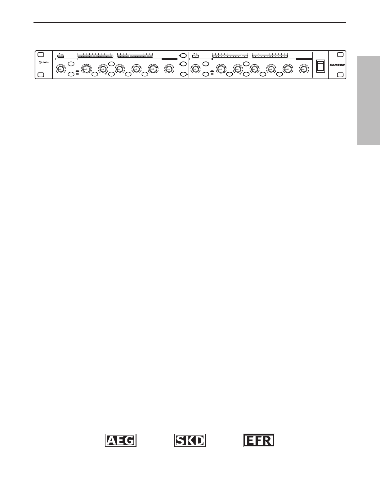
The Samson S com dynamics processor utilizes the latest technology in gain management design. Here are
some of its main features:
• Full featured, dual channel dynamics processor including Compressor/Limiter, Expander/Gate, Spectra
and Variable Enhancer.
• SKD (Smart Knee Detector) switches from soft to hard knee based on the level of input signal.
• AEG (Automatic Envelope Generator) mode constantly adjusts the Compressor’s Attack and Release
times based on input signal. Manual adjustment of Attack and Release time is also facilitated.
• 12 Segment LED Input/Output Meter, plus 12 Segment LED Gain Reduction Meter.
• External Keying with Key Listen Switch available on front panel.
• Adjustable Enhancer to restore high-end loss resulting from heavy gain reduction.
• Expander/Gate with variable Threshold control and switchable Fast and Slow Release time.
• Gate function can be switched from hard Off to Light Downward Expander.
• Gate Open and Closed LED's.
• Spectra circuit enabling mid-high frequency contour for removing sibilance.
• Advanced circuit design, utilizing low noise operational amplifiers and high quality VCAs.
• Stereo Link Switch.
• Servo balanced inputs and outputs on XLR and 1/4” connectors.
• Switchable +4 and –10 operating levels.
• High quality 41 position detent pots and backlit switches.
• The stylish bead blasted electric blue anodized front-panel is as easy to read as it is to look at.
• Three-year extended warranty.
ENGLISH
Auto Envelope
GENERATOR
Smart Knee
DETECTOR
Enhanced
Frequency
RECOVERY
STEREO
COMPRESSOR
GAIN REDUCTION dB INPUT / OUTPUT LEVEL dB
30 24 2127 18 15 9 612 4 2 1 -30 -18 -12-24 -6 -3 +3 +60 +9 +12 +18
THRESHOLDTRIGGER RATIO ATTACK RELEASE OUTPUT ENHANCER
-10
10
GATE KEY
-30
FAST
+20-40
SLOW
dB
RELEASE SPECTRA KEY AUTO I/O METER
OFF +10
20
050
dB
COMPRESSOR / LIMITEREXPANDER/GATE
4:1
50
LISTEN
62
+10
.3 300
1
dB
mSec
OFF 10
STEREO LINK
IN/OUT 1
IN/OUT 2
20
GATE
GATE KEY
050
OFF +10
dB
RELEASE
5
73
0
1
20015
3.15
-10
.05 5
Sec
+10
+20-20
dB
GAIN REDUCTION dB INPUT / OUTPUT LEVEL dB
30 24 2127 18 15 9 612 4 2 1 -30 -18 -12-24 -6 -3 +3 +60 +9 +12+18
THRESHOLDTRIGGER RATIO ATTACK RELEASE OUTPUT ENHANCER
-10
10
-30
FAST
+20-40
SLOW
dB
COMPRESSOR / LIMITEREXPANDER/GATE
4:1
50
LISTEN
62
+10
SPECTRA KEY AUTO I/O METER
.3 300
1
dB
1
20015
3.15
.05 5
mSec
Sec
Sec
0
-10
+10
+20-20
dB
CH 2
CH 2CH 1
OFF 10
POWER
5
73
Page 7
6
Controls and Functions
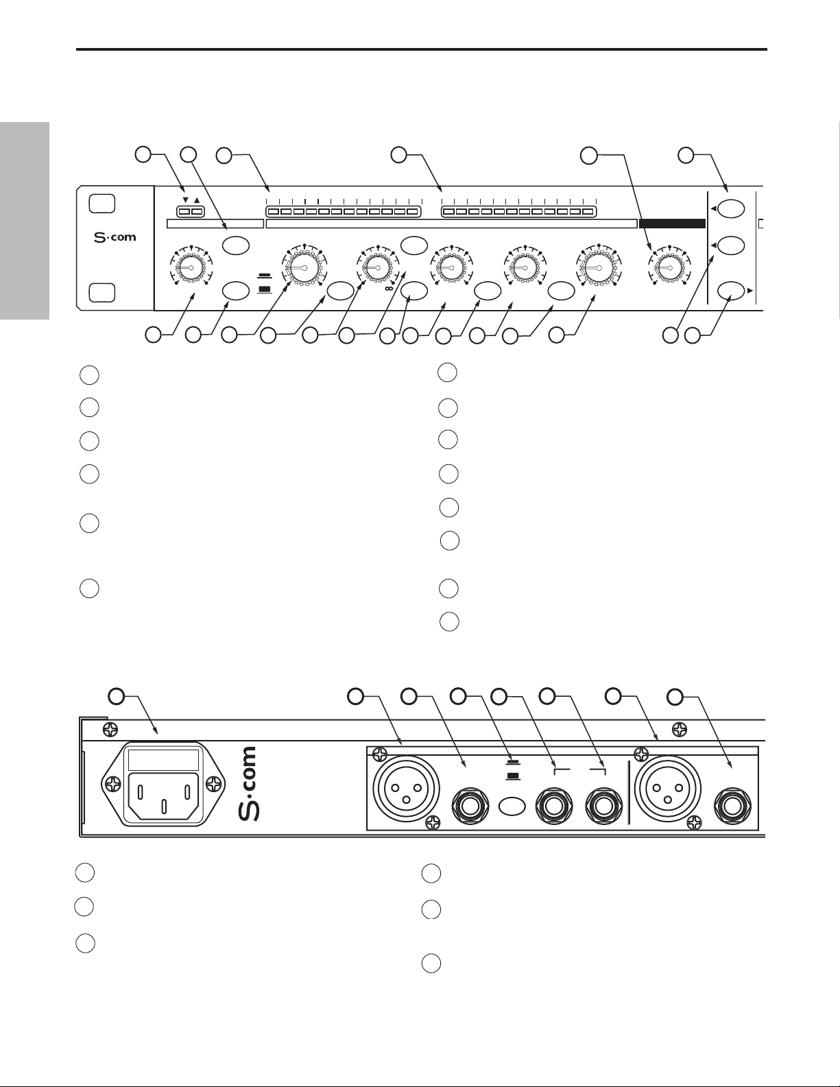
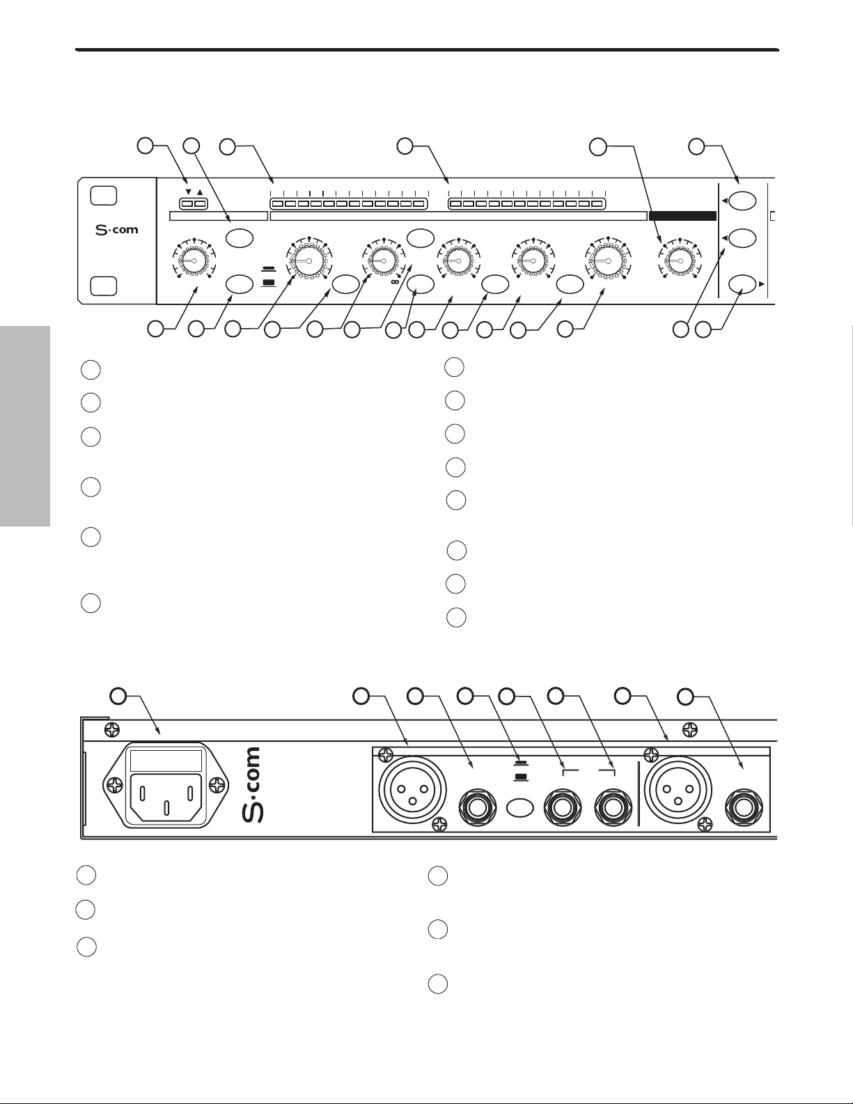
A AC INLET - IEC standard AC Power cable
Connector.
B CHANNEL 2 XLR INPUT - XLR Balanced line
input.
C CHANNEL 2 1/4”TRS INPUT - 1/4” TRS
Balanced line input.
D OPERATING LEVEL SWITCH - Switches the oper-
ating level from -10dB to +4dB.
E CHANNEL 2 KEY INPUT - Input connection
allowing external control of the S•com plus’
Compressor detection circuit.
F CHANNEL 1 KEY OUTPUT - S• com plus’ detec-
tor circuit is sent here. Use the Key Output to
process the compressor’s detector through an
external effect like an equalizer.
1 GATE OPEN & CLOSED LED - Indicates when the
gate is open and closed
2 GATE SWITCH - Selects either Gate or Expander
mode.
3 GAIN REDUCTION METER - Displays the amount of
Gain Reduction when Compressor circuit is activated.
4 INPUT/OUTPUT METER - Displays the Input or
Output signal level based on the settings of the I/O
meter switch.
5 ENHANCE LEVEL- Used to set the level of the S•
com’s Enhanced Spectrum Recovery circuit restoring
the high end loss resulting from extreme Gain
Reduction.
6 STEREO LINK SWITCH- When engaged channel 2’s
functions are controlled by the settings on channel 1.
.
0
7 CHANNEL 2 CONTROLS - The same knob and
switch complement as channel 1 .
8 MAINS POWER SWITCH -
When turned on, acti-
vates the S•com plus.
9 RACK EARS - Used for mounting into a standard 19
inch rack.
10 TRIGGER- Controls the threshold level that the
Expander/Gate becomes active.
11 RELEASE SWITCH - Selects FAST or SLOW Release
Time for EXPANDER/GATE.
12 THRESHOLD - Used to set the minimum signal
level at which the Compressor circuit begins to
function.
13 SPECTRA SWITCH - Enables the S•com’s SPECTRA
circuit for high frequency contouring.
14 RATIO - Controls the amount of Gain Reduction in
proportion to the amount of signal over the selected threshold level.
D
OUTPUT
D
UT
UT
OUTPUT
CHANNEL 2
0
ENGLISH
REAR PANEL LAYOUT
FRONT PANEL LAYOUT
1
STEREO
COMPRESSOR
OFF +10
10
2
3
30 24 2127 18 15 9 612 4 2 1 -30 -18 -12-24 -6 -3 +3 +60 +9 +12 +18
20
GATE KEY
050
dB
11
FAST
SLOW
RELEASE SPECTRA KEY AUTO I/O METER
12
13
GAIN REDUCTION dB INPUT / OUTPUT LEVEL dB
THRESHOLDTRIGGER RATIO ATTACK RELEASE OUTPUT ENHANCER
10
-10
-30
+10
+20-40
dB
14
15
4
COMPRESSOR / LIMITEREXPANDER/GATE
4:1
LISTEN
62
1
dB
17
16
50
.3 300
mSec
18
20015
19
.05 5
20
Sec
CH 1
5
OFF 10
22
6
73
23
STEREO LINK
IN/OUT 1
IN/OUT 2
5
5
1
3.15
21
0
-10
+10
+20-20
dB
A
B
-1
F G
INP
H
C
D
BALANCE
INP
E
BALANCE
Page 8
7
Controls and Functions
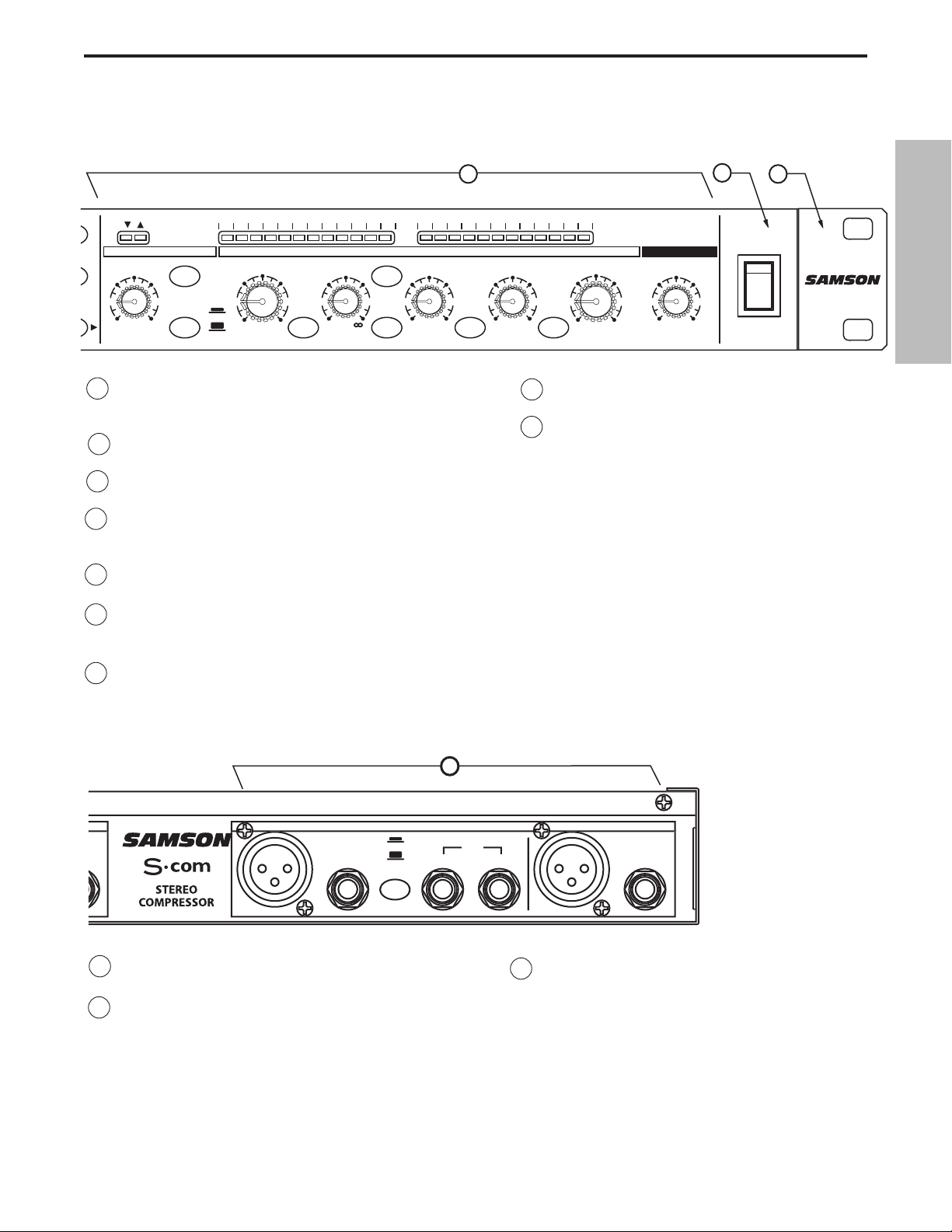
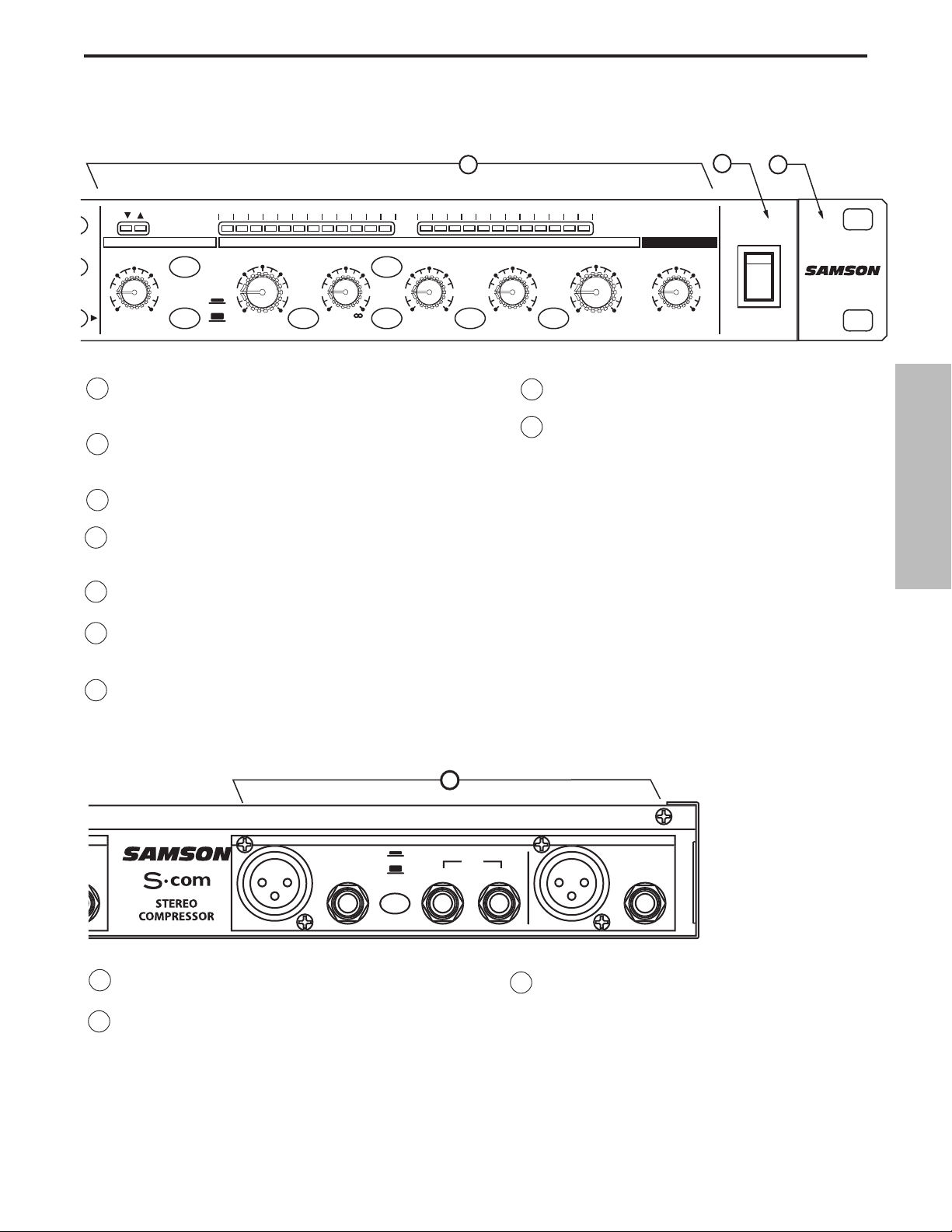
G CHANNEL 2 XLR OUTPUT - XLR Balanced line out-
put.
H CHANNEL 2 1/4”TRS OUTPUT - 1/4” TRS
Balanced line output.
I CHANNEL 1 - Same inputs and outputs as
Channel 1.
15 KEY LISTEN SWITCH - When engaged, the signal pres-
ent at the KEY INPUT is sent directly to the channel output.
16 KEY SWITCH- Selects the key input so that an external
signal may trigger the compressor.
17 ATTACK - Adjusts the amount of time the compressor
takes to reach full gain reduction.
18 AUTO - Activates S •com plus’ AEG (Auto Envelope
Generator) which dynamically adjusts the attack and
release time based on signal content.
19 RELEASE - Adjusts the length of time the compressor
takes to return the signal to it’s original level.
20 INPUT/ OUTPUT METER SELECT SWITCH - Selects
either Input or Output level to be displayed on the
Input/Output Meter.
21 LEVEL - Controls the amount of Output level.
22 CHANNEL 1 IN/OUT SWITCH- Activates
S•com Channel 1.
23 CHANNEL 2 IN/OUT SWITCH- Activates
S•com Channel 2.
D
D
OUTPUT
D
UT
UT
OUTPUT
C
1
0
ENGLISH
GAIN REDUCTION dB INPUT / OUTPUT LEVEL dB
THRESHOLDTRIGGER RATIO ATTACK RELEASE OUTPUT ENHANCER
-10
10
-30
+10
+20-40
dB
SPECTRA KEY AUTO I/O METER
COMPRESSOR / LIMITEREXPANDER/GATE
4:1
LISTEN
62
1
dB
50
.3 300
mSec
LINK
1
2
20
OFF +10
dB
30 24 2127 18 15 9 612 4 2 1 -30 -18 -12-24 -6 -3 +3 +60 +9 +12 +18
GATE KEY
GATE
050
RELEASE
FAST
SLOW
7
8
9
POWER
CH 2
CH 2
1
20015
.05 5
Sec
Sec
3.15
0
-10
+10
+20-20
dB
5
OFF 10
POWER
73
I
HANNEL
E
BALANCE
INP
-1
INP
BALANCE
Page 9
8
Operating The S•com
Whether you are an experienced audio engineer, just starting out, or you just want to experiment, follow the
steps below to get going. Further sections in this manual will cover basic dynamics and the associated parameters, system set-ups and applications for using dynamics processing in recording and live sound applications.
SETTING UP THE S•com
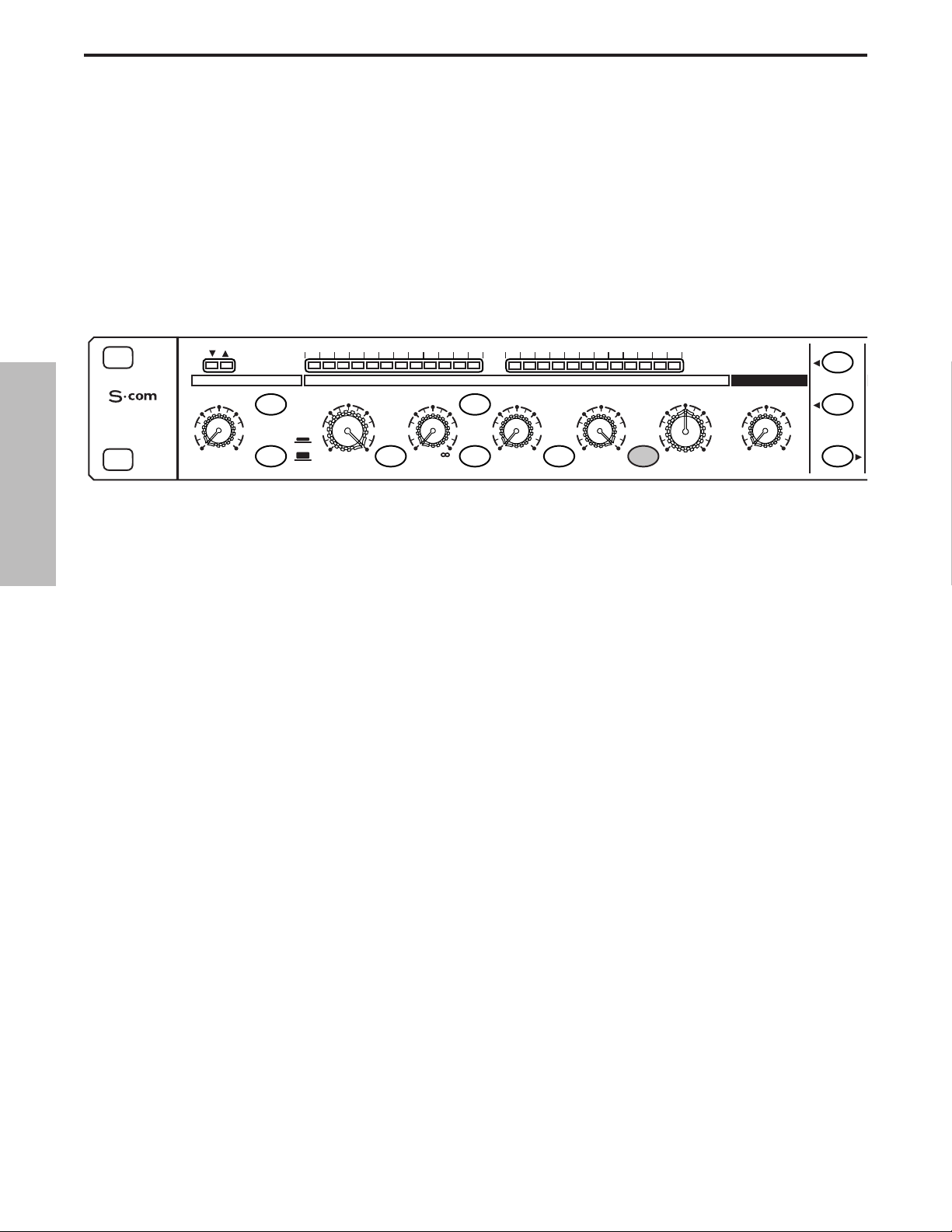
• Connect one or both sets of inputs and outputs to the designated connectors on the rear panel.
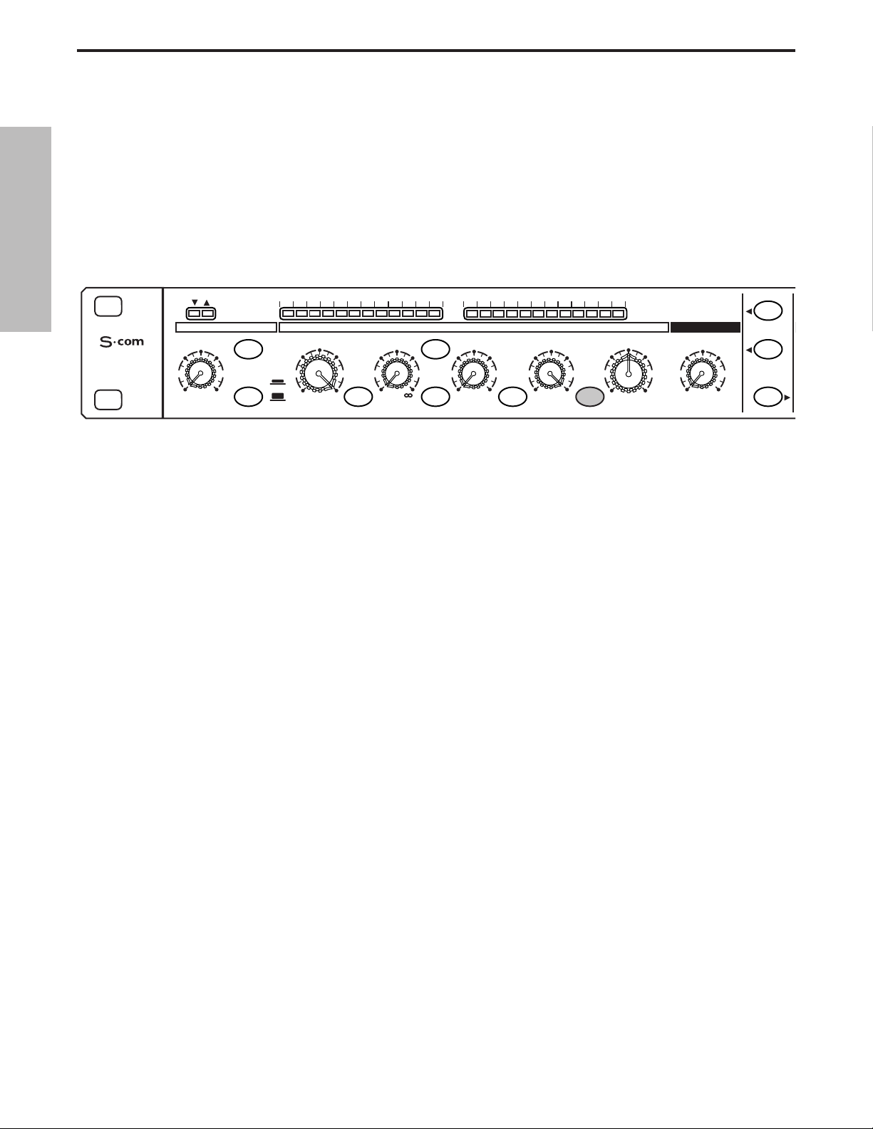
• Set the controls to the following positions:
In this configuration, the S•com is simply passing audio at unity gain with no dynamics processing. It is a good
idea to check your gain structure at this point. Use the Input/Output meter to match the level.
Send a signal to either or both of the S•com’s inputs and outputs.
• Press the METER switch to see that the input and output levels are matched.
COMPRESSING A SIGNAL
S•com's Compressor section can be used for a variety of gain management tasks including printing signals to a
multi-track recorder, as a mix-down effect, mastering, and for increasing the loudness of a live PA system. To
begin compressing your signal, follow the steps below:
• Follow the section above, “SETTING UP THE S•com” for normalizing the controls.
• Press the CHANNEL IN switch (located in the middle of the unit) to the IN position.
• Press in the AUTO switch (located in-between ATTACK and RELEASE).
• Adjust the Ratio to 2:1.
EXPANDER/GATE TRIGGER – OFF
GATE SWITCH – OUT
FAST RELEASE – OUT
COMPRESSOR THRESHOLD – +20dBu (fully clockwise)
SPECTRA - OUT
RATIO – 1:1
KEY SWITCH - OUT
ATTACK – 0.3 (fully counter-clockwise)
AUTO SWITCH- OUT
RELEASE -5 (fully clockwise)
METER SWITCH – IN
OUTPUT LEVEL – O dBu
ENHANCER - OFF (fully counter-clockwise)
STEREO LINK SWITCH – OUT
CHANNEL 1 ENGAGE – OUT
ENGLISH
STEREO
COMPRESSOR
20
OFF +10
dB
30 24 2127 18 15 9 612 4 2 1 -30 -18 -12-24 -6 -3 +3 +60 +9 +12 +18
GATE KEY
050
FAST
SLOW
RELEASE SPECTRA KEY AUTO I/O METER
GAIN REDUCTION dB INPUT / OUTPUT LEVEL dB
THRESHOLDTRIGGER RATIO ATTACK RELEASE OUTPUT ENHANCER
-10
10
-30
+10
+20-40
dB
COMPRESSOR / LIMITEREXPANDER/GATE
-10
0
+10
+20-20
dB
4:1
LISTEN
62
1
dB
50
.3 300
mSec
1
20015
.05 5
Sec
3.15
CH 1
OFF 10
STEREO LINK
5
IN/OUT 1
73
IN/OUT 2
Page 10
9
Operating The S•com
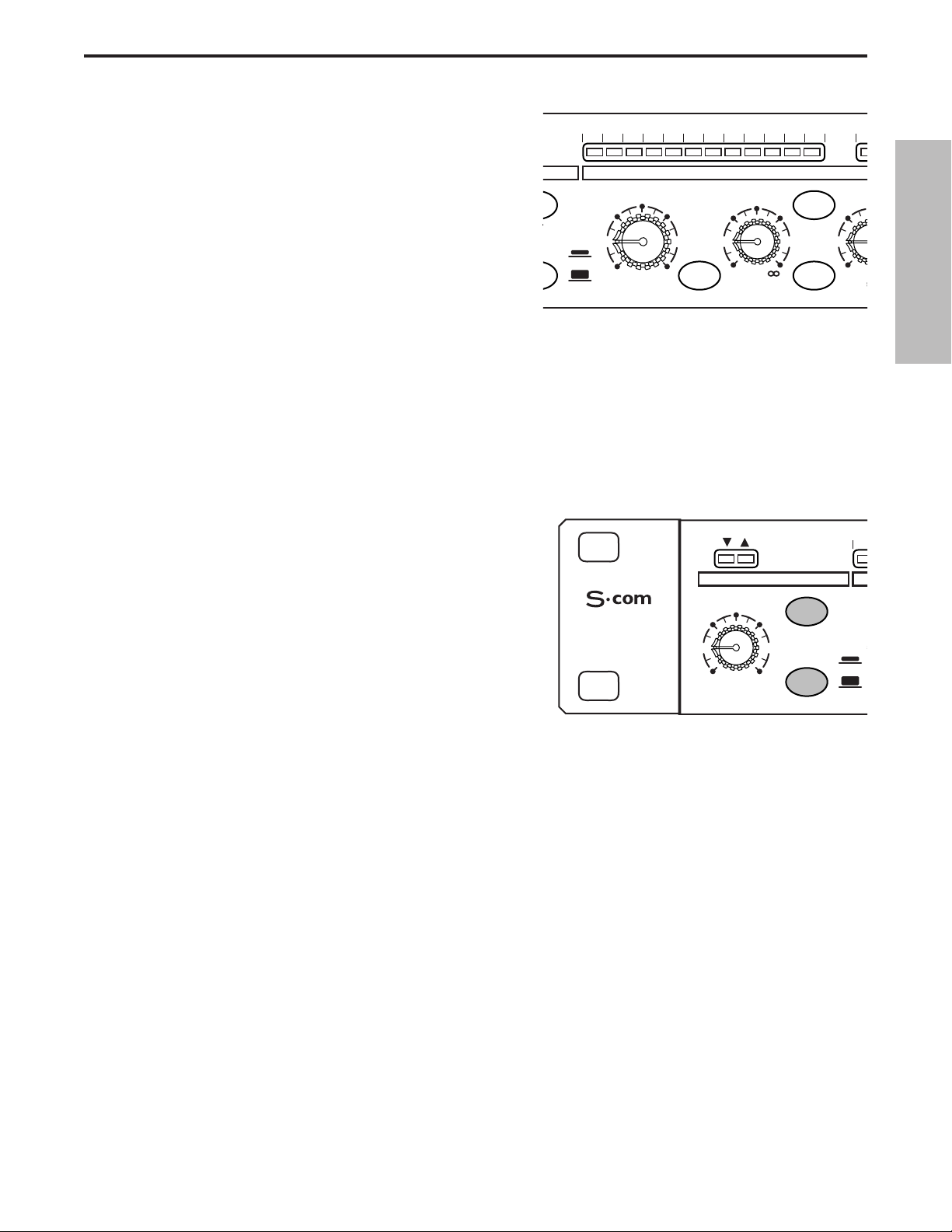
• Now gradually turn down the THRESHOLD level and
listen for the compression. For a visual representation,
the amount of compression is indicated on the GAIN
REDUCTION meter.
• Press out the AUTO button to experiment with manually
controlled ATTACK and RELEASE times.
OT
S
5
T
GATING A SIGNAL
Unwanted noises, buzzes and hisses can be easily removed by using S•com’ s GATE. The idea is to have the
Gate open only when your desired signal is playing and to mute off (Gate closed) the unwanted noise, buzz and
hiss. To Gate your signal, do the following:
• Follow the section above,” SETTING UP THE S•com” for normalizing the controls.
• To engage the Gate, make sure that the EXPANDER/GATE switch is pressed in.
0
3
• Press the RELEASE switch to the IN position to select
FAST release time.
• Now increase the THRESHOLD level and listen as the
signal begins to gate. For a visual representation of the
gate opening and closing, look at the GATE
OPEN/CLOSED LED’s located above the
EXPANDER/GATE TRIGGER control.
USING THE DOWNWARD EXPANDER
You can set the S•com's Gate section to work as a DOWNWARD EXPANDER to lower the volume of a signal.
Try the simple steps below:
• Follow the section above, “SETTING UP THE S•com” for normalizing the controls.
• To engage the EXPANDER, make sure that the EXPANDER/GATE button is switched to the OUT posi-
tion.
• Press the RELEASE switch out to select a SLOW RELEASE.
• Now increase the TRIGGER level and listen as the signal begins to get softer.
ENGLISH
30 24 2127 18 15 9 612 4 2 1 -3
E
E KEY
-30
FAST
SLOW
SE SPECTRA KEY
GAIN REDUCTION dB
THRESHOLD RATIO AT
-10
10
+10
dB
+20-40
1
4:1
dB
COMPRESS
LISTEN
62
15
.3
m
3
STEREO
COMPRESSOR
EXPANDER/GATE
TRIGGER
20
GATE
050
OFF +10
dB
RELEASE
-
FAST
SLOW
Page 11

10
Operating The S•com
USING THE ENHANCER
The S•com’s ENHANCER switch can be engaged to activate the EFR (Enhanced Frequency Recovery) circuit.
By engaging the ENHANCER, the S•com EFR restores the high frequency content that can be lost when high
gain reduction is applied. The S•com EFR achieves this by adding back the high-end of the original signal in an
amount that is equal to the amount of gain reduction.
• Follow the section above, “SETTING UP THE S•com” for normalizing the controls and run a signal such
as a CD through the S•com plus.
• Press the CHANNEL IN switch (located in the middle of the
unit) to the IN position.
• Press in the AUTO switch (located in-between ATTACK and
RELEASE).
• Adjust the Ratio to 6 - 8:1.
• Gradually turn up the ENHANCER and listen to how the
high end is restored.
USING THE SPECTRA
The S•com’s SPECTRA is a powerful tool for removing annoying problems like heavy sibilance on vocal tracks
or bright cymbals. To listen to the SPECTRA try the following:
• Follow the section above, “SETTING UP THE S•com” for nor-
malizing the controls.
• Press the CHANNEL IN switch (located in the middle of the
unit) to the IN position.
• Run a signal with extra sibilance through the S•com.
• To engage the SPECTRA, make sure that the SPECTRA
switch is pressed in.
• Now listen how S•com’s Spectra reduces the sibilance.
E
5
A
1
E
ENGLISH
30 24 2127 18 15 9 612 4 2 1
GAIN REDUCTION dB
THRESHOLD RATIO
-10
10
-30
FAST
SLOW
+10
+20-40
dB
SPECTRA KEY
COMPR
4:1
KEY
LISTEN
62
1
1
dB
+10
CH 1
ENHANCER
5
OFF 10
73
STEREO LINK
IN/OUT 1
IN/OUT 2
50
EXP
TRIGG
20
OFF +
dB
Page 12

11
Dynamics Processing 101
To begin to understand dynamics processing, we must first understand what dynamics are. Dynamics, or the
dynamic range of a signal or audio device, is the amount of level between the softest and loudest possible output. Dynamics processing is applied to a signal to manage the changes in level. Various types of processing
units are available to control dynamics including Noise Gates, Expanders, Compressors, Limiters and DeEssers. All of these processes have a unique effect on a signal, but one common element they share is that in
one way or another they control gain. Some dynamics processors control gain in a subtle way by slightly reducing how soft and loud a signal is, while others make drastic changes in gain like reducing the signal until it’s off.
Applications for dynamics processing can be categorized by two distinct groups; first, to treat a signal that has
an unpredictable dynamic range and make it predictable, and second, to create a "sound" by squeezing out the
dynamic range. Whether used for a live sound application, recording, mixing or mastering, dynamic processors
like the S•com are valuable tools for controlling gain. The following is a basic overview of dynamics processing
and how it is used to improve the quality of recorded and live sound.
COMPRESSOR
A good compressor is one of the most useful tools in live sound and recording. Compressors are used to control
the dynamic range of a signal, which offers a variety of benefits including leveling a signal that’s being recorded,
having an instrument sit in the mix, and increasing the loudness of a sound system to name a few. Drastic
amounts of compression will also result in an effect that becomes more of a sound, than just controlling gain. To
understand how a compressor works, it is necessary to become familiar with the basic parameters which include
threshold, ratio, attack time, and release time.
Threshold
Threshold is the level that once the signal exceeds, gain reduction is applied. The normal range of adjustment for
the threshold level is –40 to +20 dBu. If the threshold level is set above the highest level of the signal being sent
to the compressors, the gain reduction is never triggered. Therefore, the compressor is virtually by-passed. If
the threshold level is set very low so that any signal will trigger gain reduction, the compressor is working as an
automatic leveler.
Ratio
The ratio control is used to set the proportion of gain reduction in relationship to the input signal. For example if
the ratio is set to 2:1 and the signal crosses above the threshold level, an increase in level of 2 dB will produce a
1 dB increase in level at the output. A ratio setting of ∞ to 1 means that an infinite amount of input signal is
needed to raise the output level by 1 dB. This means that the output level stays constant even when the input
crosses over the threshold level.
Attack Time
Attack time is the amount of time that a compressor takes to effect the gain reduction after the signal rises above
the threshold level. A well-designed compressor has adjustable attack times ranging from 300 µs (microseconds) to 300 ms (milliseconds). A good compressor will sound smooth as it begins to control the gain regardless
of the attack time.
Release Time
The release time is set to control how long the compressor takes to return the input signal back to its original
level once the signal falls below the threshold level. The acceptable range for release time is from 50µs to 5 seconds. In normal use, faster release times are used for spoken word and longer release times are generally better
for instrumental music.
Auto Attack and Release
Today, sophisticated compressors often incorporate a dynamic or Auto Attack and Release mode. The S•com’s
AEG (Auto Envelope Generator) is such a mode which when engaged, automatically adjusts the attack and
release time based on the dynamically changing input signal.
ENGLISH
Page 13

12
Dynamics Processing 101 - Continued
Soft-Knee / Hard-Knee
In order to prevent harsh, unnatural envelopes on compressed signals sophisticated dynamics processors like
the S•com feature an SKD (Smart Knee Detector) or automatic knee circuit. The Smart Knee Detector automatically switches from Soft-Knee when the signal is less than 10 dB over Threshold, to Hard-Knee when the signal
is 10db above Threshold. In Soft-Knee mode, there is a gradual effect on gain change, which begins as the signal approaches the Threshold level. In Hard-Knee mode, gain reduction is linear based on the Threshold and
Ratio controls. Any signal that falls below the Threshold level will be unprocessed.
Noise Gates
Noise gates are used to remove unwanted noise and/or bleed from recorded tracks in the studio or from open
microphones in live sound systems. Noise gates can also be used as a sound effect, most commonly to chop
the end of a reverb let’s say on a snare drum so that the entire snare sound ends just before the beat. The basic
principle of a noise gate is to work as an automatic mute switch. Mute off (Gate Open) when the desired signal
is present and mute on (Gate Closed) when the desired signal is not present. In order to get the gate to work
predictably, it is necessary to set a threshold, or trigger level that will determine when the gate will open. If the
signal is below the trigger the gate will remain closed. When the signal is above the trigger, the gate will trigger
open allowing the desired signal to pass and be heard. Noise gates often have other adjustable controls like
attack, hold, range and release. Many noise gates like the S•com use sophisticated circuits to control some of
these parameters automatically.
Downward Expander
The purpose of a well-designed Downward Expander is to increase the perceived dynamic range of a system.
This is accomplished by decreasing the gain during the softer sections, thereby lowering the relative noise floor.
When the signal level is below the desired trigger level, the expander lowers the overall gain by the selected
amount.
Stereo Link Mode
The S•com can be configured from dual-mono operation to stereo by using the Stereo Link switch. In Stereo
Link mode, Channel 2 functions are controlled by the settings of Channel 1 with the exception of IN/OUT and
KEY.
Side Chain / External Key
The S•com features a side-chain or external Key function. The external Key function is used to externally
process the compressor’s detector circuit. There are many useful applications for processing the detector circuit
including Equalizing for frequency dependent compression, De-Essing - the use of EQ to remove sibilance, and
externally keying off a vocal track for Ducking effects to name a few. Selecting the Key function on S•com’s front
panel, interrupts the compressors detector path and routes it to the Key Output jack.The Key Input jack receives
the externally processed signal, which will now control the compressor’s detector.
ENGLISH
Page 14

13
Applications
Using the Expander/Gate to Remove Hiss and Noise
The S•com is an extremely useful tool in reducing the level of unwanted noises. By using the Expander/Gate you
can effectively fade the noise into the noise floor or abruptly turn the unwanted signal completely off.
Let’s say you want to reduce the bleed or cross talk that occurs when different instruments are recorded in close
proximity to each other. You have recorded an acoustic guitar simultaneously in the same room as with some
other acoustic instruments. The problem is that you hear a lot of the other instruments playing when the acoustic
guitar is silent. This can cause phasing and comb filtering problems due to microphone placement, so having the
bleeding signal drop into the noise floor is desirable.To do this, set the S•com to Expander mode with the
Release switch set to Slow and adjust the Threshold so that the acoustic guitar signal is well above the threshold
level. When the signal from the acoustic guitar track falls below the threshold level, the signal subtly fades into
the noise floor.
Now let’s say you’re attempting to remove the pick-up noise and hum from a guitar track that was recorded
through a loud amplifier. The hum and noise is most noticeable in-between the rhythm of the performance, so
you want to have the gate close during the silent parts and open during the musical passages. To do this, set the
S•com to Gate mode and adjust the Trigger level so that the gate is open just during the musical guitar parts,
and so that the gate is closed during the silent passages so that the hum and noise is muted.
Gating Drums
Using noise gates on drums is particularly useful in recording and in live sound. When a drum kit is set up with
individual microphones on each drum in a live PA system, there’s potential for great sound. However, there are
several gain management problems that can occur. Several microphones like the ones on the tom-toms, will
only be used occasionally and until the time that the tom-tom is actually played, its microphone is merely picking
up unwanted sound from other instruments on stage. This adds a lot of unwanted mush in the mix and also
adds to feedback problems. Use the S•com to gate the signal of the tom-tom by selecting Gate with the
Expander/Gate switch. Now adjust the Trigger control so that the gate opens only when the tom-tom is played,
and at the same time, so that the gate is closed even when the adjacent tom-tom is played. This same technique is useful on drums that have been recorded on individual tracks. By using the Gate to mute the bleed of
the other drums ,you can effectively reduce the comb filtering produced by phase cancellation due to microphone proximity.
Gating Longer Sounds
When using a noise-gate on sound with a longer decay like piano, it is usually necessary to use a longer release
time. Run the piano signal through the S•com and set the Expander/Gate Release switch to Slow. Adjust the
Trigger level on sustained passages to get the best results. Be sure to listen for the natural decay of the instru-
ment and allow the gate to remain open until just after end of the decay.
ENGLISH
Page 15

Leveling a Vocal Track
When recording a vocal track, the vocalist may change the distance between them and the microphone, or they
may naturally have a lot of dynamic range in their performance. In either case, the sound engineer must decide
how much compression should be used to balance the natural performance and printing a good level to tape or
disk. Set up the S•com with a medium attack and release time and a ratio of 4:1. You can also use the Auto
button to engage the AEG (Auto Envelope Generator) for automatic attack and release. Now adjust the
Threshold level so that the Gain Reduction meters show 6 to 10 dB of gain reduction. Adjust the Ratio control if
necessary.
Leveling a Guitar or Bass
Guitar and especially bass guitar can have a lot of level change between strings and even frets on the fingerboard. Using compression when recording guitars and bass will even out these differences. Set up the compressor section of the S•com with a medium attack and release time and a ratio of 4:1. You can also use the
Auto button to engage the AEG (Auto Envelope Generator) for automatic attack and release. Now adjust the
Threshold level so that the Gain Reduction meters show 10 to 12 dB of gain reduction. You’ll notice that the each
note is at the same loudness and the overall sustain is increased.
Compressing Drums
Adding compression on drums can make a boomy kick drum tighten up, almost as if you were tightening the
head of a drum. Set the S•com to a fairly quick attack time and use a ratio of 6:1. Set the Threshold so that the
Gain Reduction meter reads 12 to 15 dB. Adjust the Ratio control if necessary. You can use the same basic set
up on snare and toms as well.
Getting a Track to Sit in the Mix
By using a heavy amount of compression you can get the effect of the vocal suspending in the mix. While this
may be a bit radical for some, the effect can be dramatic especially if the vocal is mixed without any reverb or
delay. Set up the compressor section of the S•com with a medium attack and release time and a ratio of 6:1.
You can also use the Auto button to engage the AEG (Auto Envelope Generator) for automatic attack and
release. Now adjust the Threshold level to so that the Gain Reduction meters show 21 to 24 dB of gain reduc-
tion.
Speaker Protection
There are several ways to use a compressor to protect a speaker system and many considerations can be made
including whether the speaker system is crossed-over actively or passively.
If the speaker system is stereo using a passive crossover, then the line output of the mixer or equalizer is run
directly into the S•com inputs. The S•com should be last in the chain before the power amps with its outputs
feeding the inputs of the amp. Now set the S•com to Stereo Link mode and use the Auto button to engage the
AEG (Auto Envelope Generator) for automatic attack and release. Adjust the Threshold and Ratio so that the
system’s entire dynamic range is under control.
When using an active crossover, multiple compressors can be used to compress each section of the PA. For
example, if the PA is using an active crossover to run a four-way mono system, two S•coms’ can be used for four
band compression. By compressing each output of the crossover, you can maximize the output level while minimizing the gain to sensitive speakers like the mid-range. Run the low and low-mid frequencies into two channels
of the first S•com and the high-mid and high frequencies into channel one and two of the second S•com.
Applications
14
ENGLISH
Page 16

S•com System Set-Ups
LIVE SOUND SYSTEM WITH STEREO COMPRESSION
In this example, the S•com is inserted after the mixer and before the graphic equalizer,
thereby compressing the full range signal from the mixer.
15
ENGLISH
PL1602 Mixer
PL 1602
16 CHANNEL LINE MIXER
S / N
POWER
110
ON
OFF
AVIS:
RISQUE DE CHOC ELECTRIQUE
NE PAS OUVRIR
DO NOT EXPOSE THIS EQUIPMENT
TO RAIN OR MOISTURE
POWER
120V - 60 Hz 35W
RATING
CAUTION
RISK OF ELECTRIC SHOCK
~115V(0.3A)
230V(0.15A)
50/60Hz 30W
S•Com
SERIAL NUMBER
MADE IN CHINA
_ mA SLOW BLOW FUSE FOR 115V
_ mA SLOW BLOW FUSE FOR 220V
E30 Dual 15 Band EQ
E30 2/3 OCTAVE STEREO 15 BAND GRAPHIC EQUALIZER
AVIS: RISQUE DE CHOC ELECTRIQUE NE PAS OUVRIR. DO NOT EXPOSE
THIS EQUIPMENT TO RAIN OR MOISTURE.
ON
~AC INPUT
OFF
POWER
115V/230V 50/60Hz13W
BUS
INSERTS
BALANCED 600 +4db
!
MIXER LINKING
DO NOT OPEN
TIP + RING - SLEEVE GND
+4
BALANCED
CAUTION
INPUT
RISK OF ELECTRIC SHOCK
DO NOT OPEN.
POWER
RATING
RISK OF ELECTRIC SHOCK
120V - 60 Hz 20W
CAUTION
DO NOT OPEN
-10
INPUT OUTPUT
2
1
LEVEL
3
BALANCED <100Ω
0db UNITY GAIN
SERIAL NUMBER
!
S•3 Way
CH 2
HIGH
OUTPUT
2
2
2
1
1
CH 2
CH 2
MID
HIGH
3
3
3
OUTPUT
OUTPUT
MONO
MONO
HIGH-MID
HIGH
OUTPUT
OUTPUT
INPUTS BALANCED 10K‰ -30 to +4db TIP + RING - SLEEVE GND.
AUX
RETURNS
UNBALANCED 10K‰
CHANNEL 2
KEY
2
3
OUTPUTS
BALANCED
<100KΩ 0db
UNITY GAIN
CH 2
LOW
OUTPUT
2
1
1
CH 2
LOW
3
OUTPUT
2R
1L2R3L4RLRLR
1L
AUX SEND
UNBALANCED
2K‰ +4db
XLR
PIN 1 GND
BALANCED
PIN 2 HOT
OUTPUT
PIN 3 NEG
1
S com Plus
PHONE
TIP - POS
RING - NEG
SLEEVE - GND
BALANCED <100Ω
0db UNITY GAIN
CH 2
INPUT
2
1
CH 2
INPUT
3
SAMSON TECHNOLOGIES CORP., NEW YORK, U.S.A.
1L2R3L4R5L6R7L8R9L10R11L12R13L14R15L16R
6R 5L 4R 3L 2R 1L
INSERTS TIP RETURN RING SEND
CHANNEL 1
+4
KEY
BALANCED
INPUT
INPUT
-10
OUTPUT
2
1
LEVEL
3
INPUTS
BALANCED
0db UNITY GAIN
BALANCED
BALANCED
10KΩ
<100KΩ 0db
UNITY GAIN
CH 1
HIGH
OUTPUT
CH 1
HIGH
OUTPUT
CHANNEL ACHANNEL BCHANNEL ACHANNEL B
CH 1
LOW
OUTPUT
2
2
1
1
CH 1
CH 1
LOW
MID
3
3
OUTPUT
OUTPUT
MONO
MONO
LOW
LOW-MID
OUTPUT
OUTPUT
MIC 1
-10
2
3
0
1
-40+4
TRIM
-10
2
3
0
1
-40+4
TRIM
MIC 3MAIN OUT
BALANCED
OUTPUT
2
1
3
BALANCED
0db UNITY GAIN
BALANCED
10KΩ
SAMSON
TECHNOLOGIES
CORP.,
NEW YORK, U.S.A.
Servo 550 Power Amp (High)
CAUTION
RISK OF ELECTRIC SHOCK
DO NOT OPEN
F
E
U
S
SERIAL
FUSE
NUMBER
FUSE RATING
12A/250V (115V)
6A/250V (230V)
USE CLASS 2 WIRING MAXIMUM LOAD IMPEDANCE 4Ω
CAUTION
HEATSINK MAY BE
HOT! DO NOT BLOCK
AIRFLOW OR OVERHEATING MAY OCCUR
TO PREVENT SHOCK DO
GROUND
+RIGHT
NOT OPEN. NO USER
SERVICABLE PARTS
INSIDE. REFER SERVICING
TO QUALIFIED SERVICE
OUTPUT 250W/4Ω
PERSONNEL. TO PREVENT
FIRE OR SHOCK HAZARD
DO NOT EXPOSE TO RAIN
OR MOISTURE.
RIGHT
~AC INPUT
LEFT
115V/230W, 50/60HZ
510W (115V)900W (230V)
SERVO 550 STUDIO AMPLIFIER
!
LEFT+
SAMSON TECHNOLOGIES CORP., HICKSVILLE, NEW YORK
BRIDGED
TIP RING SLEEVE
SLEEVE GND
MONO STEREO
LEFT
RIGHT
INPUTS
(BALANCED
10KΩ/0dBm0)
TIP +
RING -
S1500 Power Amp (Mid)
INPUT
MODE
CHANNEL
STEREO
1 INPUT
2 WAY
2
1
CHANNEL
STEREO
1 INPUT
3 WAY
3
MONO
MONO
INPUT
4 WAY
PUSH TO RESET
115V 60Hz, 920W
OUTPUT
20A/250V
(4Ω~8Ω) (4Ω~8Ω)
~AC INPUT
(4Ω~8Ω) (4Ω~8Ω)
CH 2 CH 1
BALANCED
0dBm
TIP=HOT
TRS
RING=COLD
BALANCED
SLEEVE=GND
CH 2 CH 1
BRIDGED PARALLEL
STEREO
BALANCED
0dBm
3=COLD
XLR
2=HOT
BALANCED
1=GND
Left High / Mid
Right High / Mid
S2000 Power Amp
(Bridged Mono Low)
INPUT
OUTPUT
PUSH TO RESET
25A/250V
115V 60Hz, 1100W
(4Ω~8Ω) (4Ω~8Ω)
~AC INPUT
(4Ω~8Ω) (4Ω~8Ω)
CH 2 CH 1
BALANCED
0dBm
TRS
BALANCED
CH 2 CH 1
BRIDGED PARALLEL
STEREO
BALANCED
0dBm
TIP=HOT
3=COLD
XLR
RING=COLD
2=HOT
BALANCED
SLEEVE=GND
1=GND
Mono
Sub
Page 17
16
S•com System Set-Ups
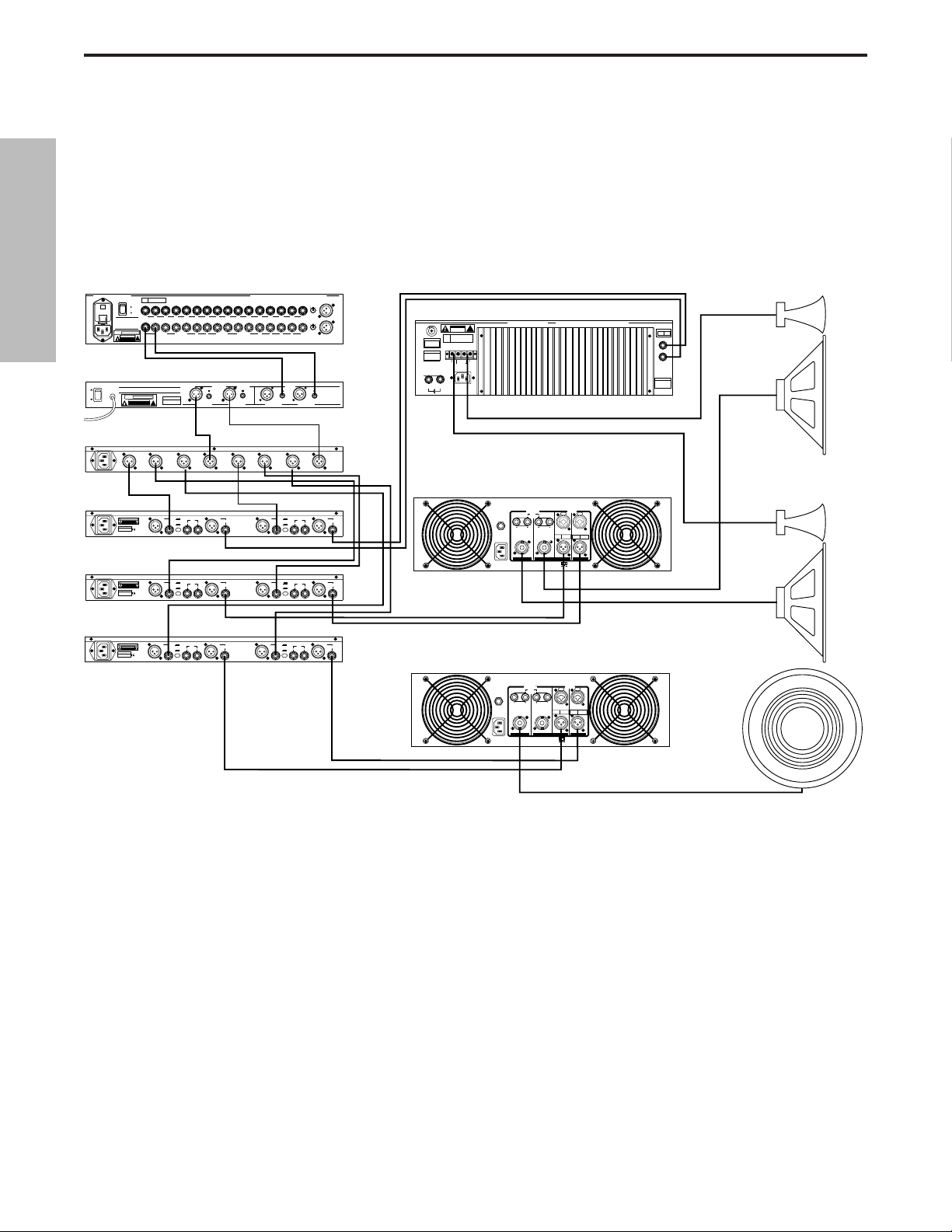
LIVE SOUND SYSTEM WITH MULTIBAND COMPRESSION
In this example, three S•com’s are inserted after the mixer, equalizer and crossover, thereby
providing individual compression on the low, mid and high frequencies.
ENGLISH
PL1602 Mixer
PL 1602
16 CHANNEL LINE MIXER
S / N
POWER
110
ON
OFF
AVIS:
RISQUE DE CHOC ELECTRIQUE
NE PAS OUVRIR
DO NOT EXPOSE THIS EQUIPMENT
TO RAIN OR MOISTURE
POWER
120V - 60 Hz 35W
RATING
CAUTION
RISK OF ELECTRIC SHOCK
~115V(0.3A)
230V(0.15A)
50/60Hz 30W
E30 Dual 15 Band EQ
ON
OFF
POWER
S•3 Way
BALANCED 600 +4db
!
DO NOT OPEN
TIP + RING - SLEEVE GND
E30 2/3 OCTAVE STEREO 15 BAND GRAPHIC EQUALIZER
AVIS: RISQUE DE CHOC ELECTRIQUE NE PAS OUVRIR. DO NOT EXPOSE
THIS EQUIPMENT TO RAIN OR MOISTURE.
~AC INPUT
POWER
120V - 60 Hz 20W
RATING
CAUTION
RISK OF ELECTRIC SHOCK
!
DO NOT OPEN
115V/230V 50/60Hz13W
CH 2
HIGH
OUTPUT
2
2
1
CH 2
HIGH
3
OUTPUT
MONO
HIGH
OUTPUT
S•Com
CAUTION
RISK OF ELECTRIC SHOCK
DO NOT OPEN.
2
SERIAL NUMBER
MADE IN CHINA
_ mA SLOW BLOW FUSE FOR 115V
_ mA SLOW BLOW FUSE FOR 220V
S•Com
CAUTION
RISK OF ELECTRIC SHOCK
DO NOT OPEN.
2
SERIAL NUMBER
MADE IN CHINA
_ mA SLOW BLOW FUSE FOR 115V
_ mA SLOW BLOW FUSE FOR 220V
S•Com
CAUTION
RISK OF ELECTRIC SHOCK
DO NOT OPEN.
2
SERIAL NUMBER
MADE IN CHINA
_ mA SLOW BLOW FUSE FOR 115V
_ mA SLOW BLOW FUSE FOR 220V
Left High / Mid
Right High / Mid
Mono
Sub
2R
1L2R3L4RLRLR
AUX SEND
UNBALANCED
2KΩ +4db
OUTPUTS
BALANCED
<100KΩ 0db
UNITY GAIN
CH 2
INPUT
2
1
CH 2
INPUT
3
SAMSON TECHNOLOGIES CORP., NEW YORK, U.S.A.
6R 5L 4R 3L 2R 1L
1L
INSERTS TIP RETURN RING SEND
BALANCED <100Ω
0db UNITY GAIN
BALANCED
0db UNITY GAIN
BALANCED
<100KΩ 0db
UNITY GAIN
CH 1
HIGH
OUTPUT
2
2
1
1
CH 1
CH 1
MID
HIGH
3
3
OUTPUT
OUTPUT
MONO
LOW-MID
OUTPUT
INPUTS BALANCED 10KΩ -30 to +4db TIP + RING - SLEEVE GND.
AUX
BUS
RETURNS
INSERTS
MIXER LINKING
UNBALANCED 10KΩ
BALANCED <100Ω
0db UNITY GAIN
SERIAL NUMBER
CH 2
LOW
OUTPUT
2
1
1
CH 2
CH 2
LOW
MID
3
3
OUTPUT
OUTPUT
MONO
HIGH-MID
OUTPUT
MIC 1
-10
2
3
0
1
-40+4
TRIM
1L2R3L4R5L6R7L8R9L10R11L12R13L14R15L16R
-10
2
3
0
1
-40+4
TRIM
MIC 3MAIN OUT
INPUTS
BALANCED
0db UNITY GAIN
BALANCED
BALANCED
10KΩ
10KΩ
SAMSON
TECHNOLOGIES
CORP.,
NEW YORK, U.S.A.
CHANNEL ACHANNEL BCHANNEL ACHANNEL B
MODE
CHANNEL
CH 1
STEREO
1 INPUT
LOW
2 WAY
OUTPUT
2
2
1
1
CH 1
CHANNEL
STEREO
LOW
1 INPUT
3 WAY
3
3
OUTPUT
MONO
MONO
MONO
LOW
INPUT
4 WAY
OUTPUT
Servo 550 Power Amp (High)
CAUTION
RISK OF ELECTRIC SHOCK
DO NOT OPEN
F
E
U
S
SERIAL
FUSE
NUMBER
FUSE RATING
12A/250V (115V)
6A/250V (230V)
USE CLASS 2 WIRING MAXIMUM LOAD IMPEDANCE 4Ω
CAUTION
HEATSINK MAY BE
HOT! DO NOT BLOCK
AIRFLOW OR OVERHEATING MAY OCCUR
TO PREVENT SHOCK DO
GROUND
+RIGHT
NOT OPEN. NO USER
SERVICABLE PARTS
INSIDE. REFER SERVICING
TO QUALIFIED SERVICE
OUTPUT 250W/4Ω
PERSONNEL. TO PREVENT
FIRE OR SHOCK HAZARD
DO NOT EXPOSE TO RAIN
OR MOISTURE.
RIGHT
~AC INPUT
LEFT
115V/230W, 50/60HZ
510W (115V)900W (230V)
SERVO 550 STUDIO AMPLIFIER
!
LEFT+
SAMSON TECHNOLOGIES CORP., HICKSVILLE, NEW YORK
BRIDGED
TIP RING SLEEVE
MONO STEREO
LEFT
RIGHT
INPUTS
(BALANCED
10KΩ/0dBm0)
TIP +
RING SLEEVE GND
S1500 Power Amp (Mid)
INPUT
PUSH TO RESET
115V 60Hz, 1100W
PUSH TO RESET
~AC INPUT
115V 60Hz, 920W
25A/250V
~AC INPUT
OUTPUT
20A/250V
(4Ω~8Ω) (4Ω~8Ω)
(4Ω~8Ω) (4Ω~8Ω)
CH 2 CH 1
OUTPUT
(4Ω~8Ω) (4Ω~8Ω)
(4Ω~8Ω) (4Ω~8Ω)
CH 2 CH 1
BALANCED
TRS
BALANCED
BRIDGED PARALLEL
BALANCED
0dBm
TIP=HOT
TRS
RING=COLD
BALANCED
SLEEVE=GND
CH 2 CH 1
BRIDGED PARALLEL
STEREO
0dBm
TIP=HOT
RING=COLD
SLEEVE=GND
CH 2 CH 1
STEREO
INPUT
BALANCED
BALANCED
0dBm
3=COLD
XLR
2=HOT
BALANCED
1=GND
BALANCED
0dBm
3=COLD
XLR
2=HOT
1=GND
CHANNEL 2
+4
KEY
BALANCED
INPUT
-10
INPUT OUTPUT
1
LEVEL
3
CHANNEL 2
+4
KEY
BALANCED
INPUT
-10
INPUT OUTPUT
1
LEVEL
3
CHANNEL 2
+4
KEY
BALANCED
INPUT
-10
INPUT OUTPUT
1
LEVEL
3
XLR
PIN 1 GND
BALANCED
PIN 2 HOT
OUTPUT
PIN 3 NEG
2
1
S com
3
PHONE
TIP - POS
RING - NEG
SLEEVE - GND
XLR
PIN 1 GND
BALANCED
PIN 2 HOT
OUTPUT
PIN 3 NEG
2
1
S com
3
PHONE
TIP - POS
RING - NEG
SLEEVE - GND
XLR
PIN 1 GND
BALANCED
PIN 2 HOT
OUTPUT
PIN 3 NEG
2
1
S com
3
PHONE
TIP - POS
RING - NEG
SLEEVE - GND
CHANNEL 1
+4
KEY
BALANCED
INPUT
2
1
3
BALANCED
INPUT
2
1
3
BALANCED
INPUT
2
1
3
BALANCED
OUTPUT
INPUT
-10
OUTPUT
2
1
LEVEL
3
CHANNEL 1
+4
KEY
BALANCED
OUTPUT
INPUT
-10
OUTPUT
2
1
LEVEL
3
CHANNEL 1
+4
KEY
BALANCED
OUTPUT
INPUT
-10
OUTPUT
2
1
LEVEL
3
S2000 Power Amp
(Bridged Mono Low)
Page 18
17
S•com Connections
Unbalanced 1/4”Connector
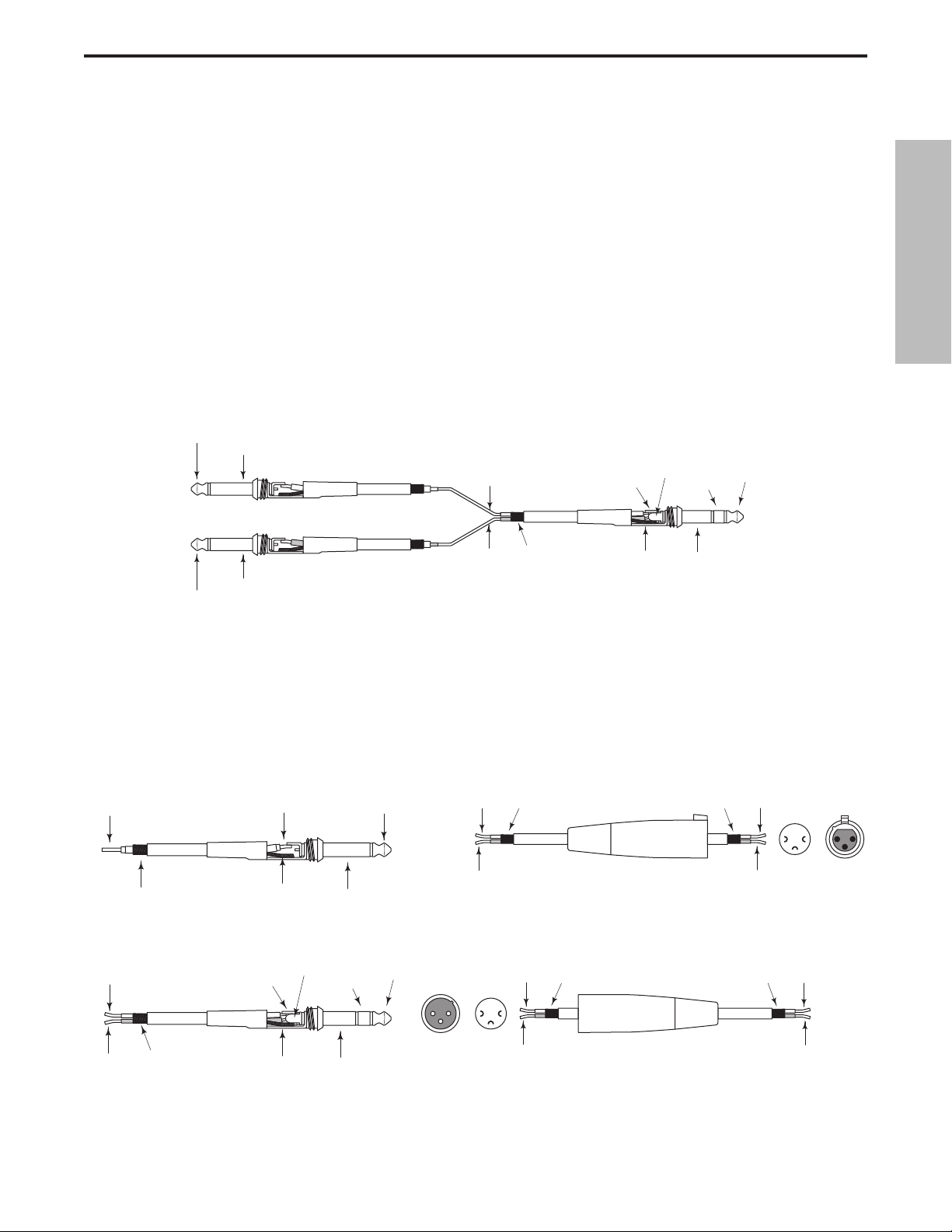
Insert Cable 1/4” male TRS connector to two male 1/4”
in send and return configuration.
XLR Balanced Wiring Guide
CONNECTING THE S•com
The are several ways to interface the S•com to support a variety of applications. The S•com features servo-balanced inputs and outputs, so connecting balanced and unbalanced signals is possible without any signal loss.
The S•com can be used on a single instrument by connecting to a channel’s insert points, or on an entire mix
"in-line" between a mixer’s outputs and a power amp or equalizer.
INSERT POINTS
Many mixers today provide channel and bus or group inserts. Insert points are input and output patch points
that interrupt the channel or bus signal so that external processors can be connected. Channel insert points are
ideal for connecting to when using the S•com to process a single channel like a vocal, bass or guitar. Bus
insert points are ideal for compressing groups of instruments like vocals, strings or drums. If you are connecting
to a channel’s insert points, you may have a single TRS jack for Send & Return. In this case, use an Insert "Y"
Cable that configured like the one in the wiring diagram below.
IN-LINE
In live sound operation the S•com can be installed in-line between a mixer and equalizer or power amplifier. For
these applications the S•com provides both 1/4" TRS connectors and XLR connectors to easily interface with
most any professional audio device. Follow the wiring examples below for your particular installation.
Balanced TRS 1/4” Connector
ENGLISH
Tip (send)
Sleeve (common)
Send (tip)
Send (tip)
Return (ring)
Ring (return)
Tip (send)
Return (ring)
Sleeve (common)
Tip (return)
Common
Common
Sleeve (common)
Signal
Ground
Ground
Tip (signal)Signal
Sleeve (ground)
Hot
Cold
Female XLR
Hot (2)
Common (1)Common
1
2
21
3
Solder Points End View
Cold (3)
3
Signal (tip)
Signal (ring)
Ground
Signal (ring)
Signal (tip)
Ground
Ring (signal)
Sleeve (ground)
Tip (signal)
2
12
3
End View Solder Points
1
3
Hot (2)
Common (1) Common
Cold (3)
Male XLR
Hot
Cold
Page 19

18
Note de Ray Kennedy
Les compresseurs et limiteurs sont des outils fondamentaux pour l’enregistrement et le mixage.
Beaucoup ne réalisent pas à quel point ils sont essentiels. Pour moi, la compression est bien plus
qu’un simple processeur de dynamique. Chaque modèle possède son propre son et se révèle idéal
pour des applications bien spécifiques. C’est pourquoi je dispose d’un choix d’environ quarante compresseurs. L’apprentissage des spécificités de chaque compresseur et de ses réglages est un
procédé qui nécessite beaucoup d’expérimentations.
Les limiteurs de crêtes et les compresseurs conviennent généralement très bien pour optimiser le
niveau des bandes ou des disques sans ajouter trop de coloration sonore.En somme, il s’agit de supprimer les crêtes et d’accentuer les passages les plus faibles d’un signal en resserrant la plage
dynamique. Des temps d’attaque et de rétablissement élevés permettent d’obtenir un son plus trans-
parent. Personnellement, j’apprécie vraiment le son de la compression et je l’utilise parfois de manière
assez poussée. Selon le type d’appareil et de réglage, vous pouvez obtenir tellement de caractéris-
tiques sonores grâce à la compression, en ajoutant de l’ambiance, en durcissant, en adoucissant le
son ou en appliquant une correction... Mon réglage de compression préféré est de “suspendre” les
voix dans le mixage, sans réverbération et intimistes, comme si le chanteur se trouvait juste devant
vous, sans que le son soit trop fort. Steve Earl, mon partenaire, dit que la compression de sa voix
durant les enregistrements permet presque à l’auditeur de savoir ce qu’il a mangé au petit-déjeuner.
De bien des manières, la compression finit par remplacer la réverbération et, poussée à l’extrême,
elle ajoute toute l’ambiance nécessaire à un micro et fait ressortir le caractère profond de vos cordes
vocales.Sur un micro d’ambiance, vous pouvez modifier la perception de la taille de la pièce en faisant
durer le son en cours de déclin. De nouveau, un long temps d’attaque et un court temps de rétablissement offrent les meilleurs résultats car vous pouvez utiliser des réglages de seuil plus poussés.
La limitation et la compression du bus stéréo est aussi une excellente manière de souder les pistes
ce qui donne l’impression que les groupes ont un son plus dense. Cela permet également d’obtenir
un niveau supérieur avant saturation lors de la copie sur deux pistes analogiques, ainsi qu’une modulation accrue des formats numériques. Il est assez fréquent que j’applique trois limiteurs stéréo avant
d’en arriver au Mastering sur disque dur et d’en garder les parties définitives qui en seront extraites.
Souvent, le fait d’appliquer plusieurs compresseurs à un même signal permet d’obtenir des résultats
intéressants, qui ne peuvent être obtenus avec un seul compresseur. Bien entendu, il n’y a pas de
règles fixes, mais il est important de savoir que le traitement du son peut être réalisé de nombreuses
façons. Certains traitements sont entièrement à lampes, d’autres lampes et optique, uniquement
optiques, transistors FET, VCA pure classe A, classe A/B, numériques, et bien d’autres combinaisons
encore.
Aujourd’hui, nous pouvons enfin disposer de VCA de très haute qualité, pas trop chers et permettant
des traitements sonores sophistiqués et polyvalents, comme les appareils S-Class de Samson.
Ray Kennedy
Ray Kennedy est producteur, ingénieur du son et parolier. Il est
basé à Nashville où se trouve la société de production
Twang Trust, créée en partenariat par Ray et le chanteur/parolier Steve Earle. Twang Trust a réalisé les enregistrements
d’artistes de renom comme Steve Earle,
Art Garfunkel, Willie Nelson et Waylon Jennings, Farm Aid,
The Del McCoury Band, Nancy Griffith, Lucinda Williams,
David Alan Coe, Shaver, V-Roys et Rosie Flores.
FRANÇAIS
Page 20
Caractéristiques du S•com
Le processeur de dynamique Samson S com utilise une technologie de pointe en matière de gestion du gain.
Voici quelques-unes de ses principales caractéristiques :
• Processeur de dynamique complet à deux canaux, avec compresseur/limiteur, expanseur/Noise Gate et
Enhancer.
• La fonction SKD (détecteur Smart Knee) permet de passer d’une courbe Soft Knee à Hard Knee, selon
le niveau d’entrée du signal.
• Le mode AEG (générateur d’enveloppe automatique) ajuste automatiquement les temps d’attaque et de
rétablissement du compresseur en fonction du signal d’entrée. Il est également possible d’effectuer un
réglage manuel des temps d’attaque et de rétablissement.
• Afficheur de niveau d’entrée/sortie 12 segments à LED et afficheur de réduction de gain 12 segments à LED.
• Possibilité de contrôle externe du circuit de commande avec commutateur Key en face avant.
• Enhancer réglable permettant de restaurer la perte des aigus résulant d’une réduction de gain massive.
• Expanseur/Noise Gate avec seuil de déclenchement variable et temps de rétablissement réglable (rapi-
de/lent).
• La fonction de Noise Gate peut être réglée de Off (désactivée) à une fonction d’expanseur léger.
• LED d’indication d’ouverture et de fermeture du Noise Gate.
• Circuit Spectra permettant un ciselage des médiums pour supprimer les sibilantes.
• Circuits haute technologie, utilisant des amplificateurs à faible bruit et des VCA de haute qualité.
• Fonction Stereo Link de couplage stéréo.
• Entrées et sorties à symétrie électronique sur connecteurs XLR et Jacks 6,35 mm.
• Niveau d’utilisation commutable +4 dBu/ -10 dBV.
• Potentiomètres crantés 41 positions de haute qualité et touches rétro-éclairées.
• L’aspect agréable de la façade stylée en acier anodisé bleu électrique facilite la lecture des réglages.
• Garantie de 3 ans.
19
FRANÇAIS
STEREO
COMPRESSOR
GAIN REDUCTION dB INPUT / OUTPUT LEVEL dB
30 24 2127 18 15 9 612 4 2 1 -30 -18 -12-24 -6 -3 +3 +60 +9 +12+18
THRESHOLDTRIGGER RATIO ATTACK RELEASE OUTPUT ENHANCER
-10
10
GATE KEY
-30
FAST
+20-40
SLOW
dB
RELEASE SPECTRA KEY AUTO I/O METER
OFF +10
20
050
dB
COMPRESSOR / LIMITEREXPANDER/GATE
4:1
50
LISTEN
62
+10
.3 300
1
dB
mSec
OFF 10
STEREO LINK
IN/OUT 1
IN/OUT 2
20
GATE
GATE KEY
050
OFF +10
dB
RELEASE
5
73
0
1
20015
3.15
-10
.05 5
Sec
+10
+20-20
dB
GAIN REDUCTION dB INPUT / OUTPUT LEVEL dB
30 24 2127 18 15 9 612 4 2 1 -30 -18 -12-24 -6 -3 +3 +60 +9 +12+18
THRESHOLDTRIGGER RATIO ATTACK RELEASE OUTPUT ENHANCER
-10
10
-30
FAST
+20-40
SLOW
dB
COMPRESSOR / LIMITEREXPANDER/GATE
4:1
50
LISTEN
62
+10
SPECTRA KEY AUTO I/O METER
.3 300
1
dB
1
20015
3.15
.05 5
mSec
Sec
Sec
0
-10
+10
+20-20
dB
CH 2
CH 2CH 1
OFF 10
POWER
5
73
Page 21
A EMBASE SECTEUR - Embase secteur IEC stan-
dard.
B ENTRÉE XLR DU CANAL 2 - Entrée ligne
symétrique sur XLR.
C ENTRÉE JACK STÉRÉO 6,35 MM DU CANAL 2 -
Entrée ligne symétrique sur Jack stéréo
6,35 mm.
DSÉLECTEUR DE NIVEAU D’UTILISATION -
Commutation du niveau d’utilisation de -10 dB à +4
dB.
E
ENTRÉE DU CIRCUIT DE COMMANDE DU CANAL
2-
Entrée permettant le contrôle externe du circuit
de commande du compresseur S•com.
F
SORTIE DU CIRCUIT DE COMMANDE DU CANAL 1
-
Le circuit de commande du S• com est affecté à
cette sortie, permettant de traiter ce circuit avec un
égaliseur externe, par exemple.
1 LED GATE OUVERT & FERMÉ - Signale lorsque le
Noise Gate est ouvert ou fermé.
2 COMMUTATEUR GATE - Sélectionne le mode Noise
Gate ou expanseur.
3 AFFICHEUR DE RÉDUCTION DE GAIN - Affiche la
réduction de gain lorsque le circuit de compression
est activé.
4 AFFICHEUR DE NIVEAU D’ENTRÉE/SORTIE - Affiche
le niveau du signal d’entrée ou de sortie selon le
réglage du commutateur.
5 ENHANCER- Ce potentiomètre détermine le niveau
du circuit Enhanced Spectrum Recovery du S•com qui
restaure la perte des aigus due aux réductions de
gain extrêmes.
6 COMMUTATEUR STEREO LINK - Lorsqu’il est activé,
les fonctions du canal 2 sont contrôlées par les
réglages du canal 1.
0
7RÉGLAGES DU CANAL 2 - Mêmes commutateurs
et potentiomètres que pour le canal 1.
8 INTERRUPTEUR POWER - Permet d’activer/désac-
tiver le S•com.
9 PLAQUES DE FIXATION DU RACK - Permettent de
fixer l’appareil dans un rack 19”standard.
10 TRIGGER - Contrôle le niveau de seuil de
déclenchement de l’expanseur/Noise Gate.
11 COMMUTATEUR RELEASE - Sélectionne le temps
de rétablissement rapide ou lent de
l’expanseur/Noise Gate.
12 THRESHOLD - Détermine le niveau de seuil à partir
duquel le circuit du compresseur se déclenche.
13 SPECTRA - Active le circuit SPECTRA du S•com pour
le modelage des aigus.
14 RATIO - Détermine le taux de compression
appliqué au signal à partir du niveau de seuil.
D
OUTPUT
D
UT
UT
OUTPUT
CHANNEL 2
0
20
FRANÇAIS
Réglages et fonctions
FACE ARRIÈRE
FACE AVANT
10
2
20
OFF +10
dB
11
3
30 24 2127 18 15 9 612 4 2 1 -30 -18 -12-24 -6 -3 +3 +60 +9 +12 +18
GATE KEY
050
FAST
SLOW
RELEASE SPECTRA KEY AUTO I/O METER
12
13
GAIN REDUCTION dB INPUT / OUTPUT LEVEL dB
THRESHOLDTRIGGER RATIO ATTACK RELEASE OUTPUT ENHANCER
10
-10
-30
+10
+20-40
dB
14
15
4
COMPRESSOR / LIMITEREXPANDER/GATE
4:1
62
1
dB
16
1
STEREO
COMPRESSOR
5
CH 1
0
-10
+10
+20-20
dB
5
OFF 10
22
LISTEN
17
50
.3 300
mSec
18
20015
19
.05 5
20
1
3.15
Sec
21
6
73
23
STEREO LINK
IN/OUT 1
IN/OUT 2
5
A
B
C
D
BALANCE
INP
E
F G
-1
INP
H
BALANCE
Page 22
G SORTIE XLR DU CANAL 2 - Sortie ligne symétrique
sur connecteur XLR.
H SORTIE JACK STÉRÉO 6,35 MM DU CANAL 2 -
Sortie ligne symétrique sur Jack stéréo 6,35 mm.
I CHANNEL 1 - Mêmes entrées et sorties que
le canal 2.
15 COMMUTATEUR KEY LISTEN - Lorsqu’il est activé,le
signal en entrée KEY INPUT est directement transmis à la
sortie du canal.
16 COMMUTATEUR KEY - Sélectionne l’entrée du circuit de
commande de sorte qu’un signal externe puisse
déclencher le compresseur.
17 ATTACK - Détermine le temps d’attaque du com-
presseur (jusqu’à la réduction de gain max.).
18 AUTO - Active le générateur d’enveloppe automatique
(AEG) du S •com, qui règle l’attaque et le rétablissement
de manière dynamique en fonction du signal.
19 RELEASE - Détermine le temps de rétablissement du
compresseur (retour du signal au niveau initial).
20 COMMUTATEUR DE L’AFFICHEUR
D’ENTRÉE/ SORTIE - Sélectionne l’affichage du niveau
d’entrée ou de sortie.
21 OUTPUT - Contrôle le niveau de sortie.
22 CHANNEL 1 IN/OUT - Active le canal 1 du
S•com.
23 CHANNEL 2 IN/OUT - Active le canal 2 du
S•com.
D
D
OUTPUT
D
UT
UT
OUTPUT
C
1
0
21
FRANÇAIS
Réglages et fonctions
GAIN REDUCTION dB INPUT / OUTPUT LEVEL dB
THRESHOLDTRIGGER RATIO ATTACK RELEASE OUTPUT ENHANCER
-10
10
-30
+10
+20-40
dB
SPECTRA KEY AUTO I/O METER
COMPRESSOR / LIMITEREXPANDER/GATE
4:1
LISTEN
62
1
dB
50
.3 300
mSec
20015
LINK
1
2
20
OFF +10
dB
30 24 2127 18 15 9 612 4 2 1 -30 -18 -12-24 -6 -3 +3 +60 +9 +12 +18
GATE
GATE KEY
050
RELEASE
FAST
SLOW
7
CH 2
CH 2
1
.05 5
Sec
Sec
3.15
0
-10
+10
+20-20
dB
OFF 10
8
5
73
POWER
POWER
9
I
HANNEL
E
BALANCE
INP
-1
INP
BALANCE
Page 23
Utilisation du S•com
Que vous soyez un ingénieur du son expérimenté ou amateur, suivez les étapes ci-dessous pour configurer
votre appareil. Les sections suivantes définissent les principes de la dynamique et les paramètres associés,
ainsi que les configurations système et les applications de traitement de la dynamique en enregistrement et sur
scène.
CONFIGURATION DU S•com
• Reliez les entrées/sorties aux connecteurs correspondants en face arrière.
• Placez les réglages dans les positions illustrées ci-dessous :
Dans cette configuration, le S•com laisse passer le signal à gain unitaire, sans traitement de la dynamique.
Vérifiez les réglages de gain avec cette configuration. Utilisez l’afficheur d’entrée/sortie pour vérifier que les
niveaux correspondent.
Appliquez un signal à l’une des entrées/sorties du S•com, ou aux deux.
• Appuyez sur la touche I/O METER pour vérifier que les niveaux d’entrée/sortie correspondent.
COMPRESSION D’UN SIGNAL
La section compresseur du S•com peut être utilisée pour différentes tâches de gestion du gain, lors d’enregistrement de signaux sur un enregistreur multipiste, comme effet au mixage final, lors du Mastering et pour augmenter le niveau sonore global d’un système de sonorisation. Procédure de compression d’un signal :
• Suivez la section ci-dessus, “CONFIGURATION DU S•com”, pour normaliser les réglages.
• Placez la touche CHANNEL IN (au centre de l’appareil) en position enfoncée.
• Placez la touche AUTO (entre ATTACK et RELEASE) en position enfoncée.
• Réglez le taux (Ratio) sur 2:1.
EXPANDER/GATE TRIGGER – OFF
Commutateur GATE – Position haute
RELEASE – Position haute (rétablissement rapide)
COMPRESSOR THRESHOLD – +20 dBu (max. à droite)
SPECTRA - Position haute
RATIO – 1:1
Commutateur KEY - Position haute
AT TAC K – 0,3 (maximum à gauche)
Commutateur AUTO - Position haute
RELEASE - 5 (max. à droite)
Commutateur METER – Position enfoncée
OUTPUT LEVEL – O dBu
ENHANCER - 0 (maximum à gauche)
Commutateur STEREO LINK – Position haute
Touche CHANNEL 1 – Position haute
22
FRANÇAIS
30 24 2127 18 15 9 612 4 2 1 -30 -18 -12-24 -6 -3 +3 +60 +9 +12 +18
STEREO
COMPRESSOR
20
OFF +10
dB
GATE KEY
050
FAST
SLOW
RELEASE SPECTRA KEY AUTO I/O METER
GAIN REDUCTION dB INPUT / OUTPUT LEVEL dB
THRESHOLDTRIGGER RATIO ATTACK RELEASE OUTPUT ENHANCER
-10
10
-30
+10
+20-40
dB
COMPRESSOR / LIMITEREXPANDER/GATE
-10
0
+10
+20-20
dB
4:1
LISTEN
62
1
dB
50
.3 300
mSec
20015
1
.05 5
Sec
3.15
CH 1
5
OFF 10
73
STEREO LINK
IN/OUT 1
IN/OUT 2
Page 24
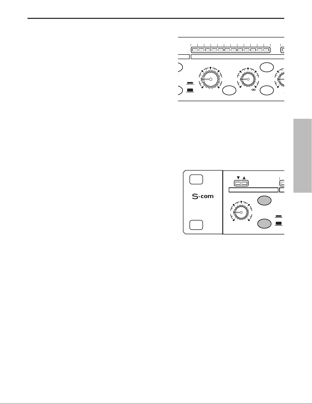
Utilisation du S•com
• À présent, tournez progressivement le potentiomètre
THRESHOLD et écoutez la compression obtenue. Vous
disposez d’une représentation visuelle de la
compression sur l’afficheur GAIN REDUCTION.
• Appuyez sur la touche AUTO (position haute) pour
obtenir un réglage manuel des temps d’attaque
(ATTACK) et de rétablissement (RELEASE).
OT
S
5
T
UTILISATION DU NOISE GATE
Les bruits parasites, ronflements et souffles indésirables peuvent aisément être supprimés à l’aide du Noise
Gate du S•com. Principe : Le Noise Gate doit être ouvert sur le signal souhaité et fermé pour couper tous les
parasites sonores. Pour appliquer le Noise Gate à votre signal, procédez comme suit :
• Suivez la section ci-avant, “CONFIGURATION DU S•com”, pour normaliser les réglages.
• Pour activer le Noise Gate, assurez-vous que la touche EXPANDER/GATE est enfoncée.
0
3
• Appuyez sur le commutateur RELEASE (position
enfoncée) pour sélectionner un temps de rétablissement
rapide.
• Ensuite, augmentez le niveau de seuil et écoutez l’im-
pact du Noise Gate sur le son. Pour une représentation
visuelle de l’ouverture/fermeture du Noise Gate, consultez les LED situées au-dessus du réglage
EXPANDER/GATE TRIGGER.
UTILISATION DE L’EXPANSEUR
Vous pouvez configurer la section Noise Gate du S•com pour qu’elle fonctionne comme EXPANSEUR afin de
diminuer le volume d’un signal. Suivez la procédure ci-dessous :
• Suivez la section ci-avant, “CONFIGURATION DU S•com”, pour normaliser les réglages.
• Pour activer l’expanseur, assurez-vous que la touche EXPANDER/GATE n’est pas enfoncée.
• Placez la touche RELEASE en position haute pour sélectionner une vitesse de rétablissement lente.
• Ensuite, augmentez progressivement le réglage TRIGGER. Vous constatez que le signal devient plus
faible.
23
FRANÇAIS
30 24 2127 18 15 9 612 4 2 1 -3
E
E KEY
-30
FAST
SLOW
SE SPECTRA KEY
GAIN REDUCTION dB
THRESHOLD RATIO AT
-10
10
+10
dB
+20-40
1
4:1
dB
COMPRESS
LISTEN
62
EXPANDER/GATE
STEREO
COMPRESSOR
TRIGGER
20
OFF +10
dB
GATE
050
RELEASE
15
FAST
SLOW
.3
m
3
-
Page 25
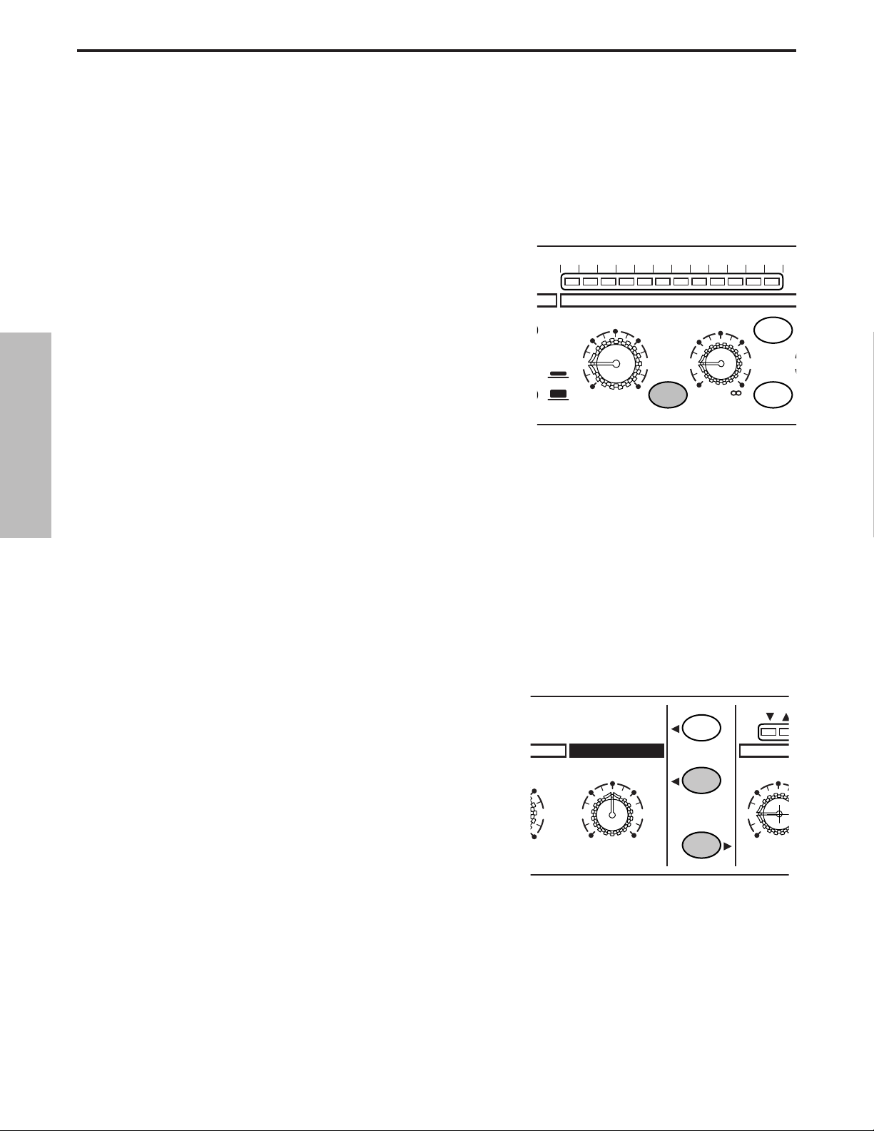
Utilisation du S•com
UTILISATION DE L’ENHANCER
Appuyez sur la touche ENHANCER du S•com (position enfoncée) pour activer le circuit EFR (Enhanced
Frequency Recovery). Lorsque l’Enhancer est activé, le circuit EFR du S•com rétablit le contenu hautes
fréquences qui est perdu lorsqu’une forte réduction de gain est appliquée. Le circuit EFR du S•com restaure les
aigus du signal initial en prenant une valeur proportionnelle à la réduction de gain.
• Suivez la section ci-avant, “CONFIGURATION DU S•com”, pour normaliser les réglages et appliquez un
signal (comme un CD) au S•com.
• Appuyez sur la touche CHANNEL IN (située au centre de
l’appareil), de sorte qu’elle soit en position enfoncée.
• Placez la touche AUTO (située entre ATTACK et RELEASE)
en position enfoncée.
• Réglez le potentiomètre Ratio sur 6 - 8:1.
• Montez progressivement le potentiomètre ENHANCER.
Vous constatez que les aigus sont restaurés.
UTILISATION DU CIRCUIT SPECTRA
Le SPECTRA du S•com est un outil puissant permettant de se débarasser de problèmes comme les excès de
sibilantes sur les pistes vocales ou les cymbales claires. Pour écouter
l’effet du SPECTRA, suivez la procédure ci-dessous :
• Suivez la section ci-avant, “CONFIGURATION DU S•com”,
pour normaliser les réglages.
• Appuyez sur la touche CHANNEL IN (située au centre de l’ap-
pareil), de sorte qu’elle soit en position enfoncée.
• Affectez un signal avec un excès de sibilantes au S•com.
• Pour activer le circuit SPECTRA, assurez-vous que le commu-
tateur SPECTRA est en position enfoncée.
•Écoutez à présent la réduction des sibiliantes induite par le
Spectra du S•com.
E
5
A
1
E
24
FRANÇAIS
30 24 2127 18 15 9 612 4 2 1
-30
FAST
SLOW
GAIN REDUCTION dB
THRESHOLD RATIO
-10
10
+10
+20-40
dB
SPECTRA KEY
COMPR
4:1
KEY
LISTEN
62
1
1
dB
+10
CH 1
ENHANCER
5
OFF 10
STEREO LINK
IN/OUT 1
73
IN/OUT 2
50
EXP
TRIGG
20
OFF +
dB
Page 26

Éléments de base sur les processeurs de dynamique
Pour comprendre les notions relatives au traitement de la dynamique, nous devons tout d’abord comprendre ce
qu’est la dynamique. La dynamique ou plage dynamique d’un signal ou d’un appareil audio correspond à la différence entre le niveau le plus faible et le niveau le plus élevé du signal de sortie. Le traitement de la dynamique
est destiné à modifier cette différence de niveau. Différents types de processeurs permettent de contrôler la
dynamique : Noise Gate, expanseurs, compresseurs, limiteurs et dé-esseurs.Tous ces processeurs ont un effet
unique sur le signal. Cependant, tous procèdent par contrôle du gain. Certains processeurs de dynamique contrôlent le gain de manière subtile, en modifiant le niveau sonore du signal, et d’autres modifient le gain de
manière radicale, allant jusqu’à couper le signal. Les applications du traitement de la dynamique peuvent être
classées en deux groupes distincts. Le premier traite un signal présentant une plage dynamique imprévisible
afin de la rendre prévisible. Le second tente de créer un “son nouveau” par transformation de la plage
dynamique. Que vous les utilisiez pour des applications de sonorisation, pour l’enregistrement, le mixage ou le
Mastering, les processeurs de dynamique comme le S•com sont des outils indispensables au contrôle du gain.
Voici une présentation du traitement de la dynamique et comment s’en servir pour améliorer la qualité des
enregistrements et des sons live.
COMPRESSEUR
Un bon compresseur est l’un des outils les plus utiles destinés aux enregistrements et sons live. Les compresseurs permettent de contrôler la plage dynamique d’un signal. Ils offrent de nombreux avantages : nivelage
d’un signal enregistré, mise en valeur d’un instrument au mixage et augmentation du niveau sonore d’un système de sonorisation, pour n’en citer que quelques-uns. Une compression très élevée permet en outre d’obtenir
un effet qui s’apparente plus à un effet sonore spécifique qu’à une simple gestion automatique du gain. Pour
comprendre le fonctionnement d’un compresseur, il est nécessaire de se familiariser avec les paramètres de
base (seuil, taux de compression, temps d’attaque et de rétablissement).
Seuil
Le seuil est le niveau que le signal doit dépasser pour activer la réduction de gain. La plage de réglage normale
du niveau de seuil se situe entre -40 et +20 dBu. Si le seuil dépasse le niveau le plus élevé du signal affecté au
compresseur, la réduction de gain n’est jamais appliquée. Par conséquent, le compresseur est virtuellement
bypassé. Si le niveau de seuil est réglé très bas, le moindre signal déclenche la réduction de gain et le compresseur fonctionne alors en limiteur.
Taux
Le taux détermine la proportion de réduction de gain par rapport au niveau du signal d’entrée. Par exemple, si le
taux est réglé sur 2:1 et que le signal dépasse le niveau de seuil, une augmentation de 2 dB du signal d’entrée
produit seulement une augmentation de 1 dB en sortie. Un taux de ∞:1 signifie qu’il faut que le niveau du signal
d’entrée augmente d’une valeur infinie pour que le niveau de sortie augmente de 1 dB. En conséquence, le
niveau de sortie reste constant, même lorsque le signal d’entrée dépasse le niveau de seuil.
Temps d’attaque
Le temps d’attaque détermine le temps que met le compresseur à appliquer la réduction de gain après que le
signal ait dépassé le niveau de seuil. Un compresseur bien conçu offre une plage de réglage du temps d’attaque
allant de 300 µs (microsecondes) à 300 ms (millisecondes). Un bon compresseur doit offrir un son homogène
lorsqu’il commence à contrôler le gain, quelque soit le temps d’attaque sélectionné.
Temps de rétablissement
Le temps de rétablissement détermine le temps que met le compresseur à rétablir le niveau initial du signal
d’entrée lorsque le signal repasse sous le niveau de seuil. Plage de réglage acceptable : 50 µs à 5 secondes.
Généralement, on utilise des temps de rétablissement courts pour le discours (voix parlée) et des temps de
rétablissement plus longs pour les parties instrumentales.
Attaque et rétablissement automatiques
Aujourd’hui, les compresseurs sophistiqués sont souvent équipés d’un mode d’attaque et de rétablissement
automatiques. Le générateur d’enveloppe automatique (AEG) endosse cette fonction sur le S•com. Lorsqu’il est
activé, il règle automatiquement l’attaque et le rétablissement en fonction de la variation dynamique du signal
d’entrée.
25
FRANÇAIS
Page 27

Éléments de base sur les processeurs de dynamique - Suite
Soft-Knee/Hard-Knee
Pour éviter les enveloppes dures ou non naturelles sur les sons compressés, les processeurs de dynamique
sophistiqués, comme le S•com, sont équipés d’un détecteur intelligent Smart Knee (SKD), soit un circuit Knee
automatique. Le SKD sélectionne automatiquement le mode Soft Knee lorsque le signal est inférieur à 10 dB
au-dessus du seuil, et le mode Hard Knee lorsque le signal atteint les 10 dB au-dessus du seuil. En mode Soft
Knee, la variation du gain se fait de manière progressive. Elle commence alors que le signal approche du niveau
de seuil. En mode Hard Knee, la réduction de gain est linéaire, basée sur les réglages de seuil et de taux de
compression. Le traitement s’arrête lorsque le signal repasse sous le niveau de seuil.
Noise Gate
Le Noise Gate permet de supprimer les bruits parasites des pistes enregistrées en studio ou des micros ouverts
des systèmes de sonorisation live. Le Noise Gate peut également être utilisé comme effet, généralement pour
couper la fin d’une réverbération (par exemple, sur une caisse claire, afin que la totalité du son de la caisse claire
se termine juste avant le temps). Le principe de base d’un Noise Gate est de fonctionner comme un Mute
automatique. Le Mute est désactivé (Noise Gate ouvert) en présence du signal souhaité et le Mute est activé
(Noise Gate fermé) en absence du signal souhaité. Pour contrôler le fonctionnement du Noise Gate, il est néces-
saire de définir un niveau de seuil ou de déclenchement, déterminant l’ouverture du Noise Gate. Si le signal se
trouve sous le niveau de seuil, le Noise Gate reste fermé. Lorsque le signal dépasse ce niveau, le Noise Gate
s’ouvre, laissant ainsi passer le signal (que vous pouvez alors entendre). Le Noise Gate dispose souvent de
réglages, comme l’attaque, le maintien, la plage et le rétablissement. Nombre de Noise Gates, comme le S•com,
utilisent des circuits sophistiqués permettant un contrôle automatique de certains paramètres.
Expanseur
Le but d’un expanseur bien conçu est d’augmenter la plage dynamique perçue d’un système. Pour cela, il diminue le gain des passages les plus faibles, ce qui diminue le bruit de fond relatif. Lorsque le niveau du signal se
trouve sous le niveau de déclenchement souhaité, l’expanseur diminue le gain global selon la valeur sélection-
née.
Mode de couplage stéréo
Le S•com peut être configuré en mode double mono ou en mode stéréo grâce au commutateur Stereo Link. En
mode stéréo, les fonctions du canal 2 sont contrôlées par les réglages du canal 1, à l’exception des commuta-
teurs IN/OUT et KEY.
Circuit de commande/Contrôle externe (entrée External Key)
Le S•com dispose d’une fonction de contrôle par signal externe du circuit de commande. Elle permet de traiter le
signal du circuit de commande par un processeur externe. Cette fonction a de nombreuses applications utiles :
compression sélective en fréquence, dé-essing pour corriger les excès de sibilantes, contrôle du circuit de commande par un signal externe (contrôle externe d’une piste vocale pour les effets de Ducking), etc. Lorsque vous
sélectionnez la fonction Key en façade du S•com, le trajet du circuit de commande des compresseurs est interrompu pour être affecté à la sortie du circuit de commande (Key Output). L’entrée du circuit de commande (Key
Input) reçoit le signal traité par un processeur externe, qui contrôle alors le circuit de commande du compresseur.
26
FRANÇAIS
Page 28

Applications
Utilisation de l’expanseur/Noise Gate pour supprimer le souffle et le bruit
Le S•com s’avère être un outil très utile pour réduire le niveau des bruits parasites. Grâce à l’expanseur/Noise
Gate, vous pouvez occulter les bruits parasites dans le bruit de fond ou les supprimer complètement.
Vous souhaitez par exemple réduire la diaphonie ou la reprise de signaux non souhaités par un micro,
phénomènes qui se produisent lorsque différents instruments sont très proches durant l’enregistrement. Vous
avez enregistré une guitare acoustique en même temps que d’autres instruments acoustiques, dans la même
pièce. Problème : vous entendez trop les autres instruments lorsque la guitare acoustique ne joue pas. Cela
peut entraîner des problèmes de déphasage et de filtrage en peigne en raison du placement des micros. Il est
donc préférable de réduire la reprise de signaux non souhaités au même niveau que le niveau du bruit de fond.
Pour cela, réglez le S•com en mode expanseur, réglez la touche Release en rétablissement lent et réglez le
seuil de sorte que le signal de la guitare acoustique soit largement au-dessus du niveau de seuil. Lorsque le signal de la piste de guitare acoustique passe sous le niveau de seuil, le signal se fond subtilement dans le bruit de
fond.
À présent, imaginons que vous essayez de supprimer le bruit et le ronflement des micros d’une piste de guitare
enregistrée à l’aide d’un amplificateur puissant. Le bruit et le ronflement se remarquent particulièrement durant
les passages silencieux de l’enregistrement. Vous souhaitez donc que le Noise Gate se ferme durant les parties
silencieuses et s’ouvre lors des passages musicaux. Pour cela, réglez le S•com en mode Noise Gate. Réglez le
niveau de déclenchement (potentiomètre Trigger) de sorte que le Noise Gate s’ouvre uniquement durant le jeu
de la guitare et qu’il se ferme lors des passages silencieux afin de couper le bruit et le ronflement.
Application du Noise Gate à la batterie
L’application du Noise Gate à la batterie est particulièrement utile en enregistrement et en situation live.
Lorsqu’une batterie est configurée avec des micros sur chaque élément dans un système de sonorisation de
scène, le son peut potentiellement être excellent. Cependant, plusieurs problèmes de contrôle du gain risquent
d’apparaître. Plusieurs micros, comme celui d’un tom, ne serviront qu’occasionnellement. Or, tant que le batteur
ne joue pas sur ce tom, le micro reprend simplement les sons des autres instruments de la scène. Cela ajoute
beaucoup de bruit indésirable dans le mixage et pose également des problèmes de Larsen. Utilisez le S•com
pour couper le signal du tom en sélectionnant le Noise Gate à l’aide de la touche Gate. Ensuite, réglez le potentiomètre Trigger afin que le Noise Gate s’ouvre uniquement lorsque le tom est frappé et qu’il se ferme, même
lorsque le tom adjacent est frappé. Cette technique est également utile pour les éléments de batterie enregistrés
sur des pistes individuelles. En utilisant le Noise Gate pour couper la reprise par micros des autres éléments de
batterie, vous pouvez efficacement réduire le filtrage en peigne causé par l’annulation de phase due à la proximité des micros.
Application du Noise Gate aux sons longs
Lorsque vous utilisez un Noise Gate sur un signal présentant un long déclin, comme un piano, il est généralement nécessaire de sélectionner un temps de rétablissement plus long. Appliquez le signal du piano au
processeur S•com et réglez la touche Release de l’expanseur/Noise Gate sur un rétablissement lent. Réglez le
potentiomètre Trigger sur les passages soutenus pour obtenir les meilleurs résultats. Veillez à respecter le déclin
naturel de l’instrument et à ce que le Noise Gate reste ouvert jusqu’au point situé juste après la fin du déclin.
27
FRANÇAIS
Page 29

Niveler la dynamique d’une piste de chant
Lorsque vous enregistrez une piste de chant, il se peut que le chanteur se déplace plus ou moins loin du micro
ou il se peut que l’enregistrement ait naturellement une plage dynamique importante. Le cas échéant, l’ingénieur
du son doit décider de la compression à appliquer pour équilibrer l’enregistrement sur bande ou sur disque.
Configurez le S•com avec des temps d’attaque et de rétablissement moyens et un taux de compression de 4:1.
Vous pouvez également appuyer sur la touche Auto pour activer le générateur d’enveloppe automatique (AEG)
qui calcule automatiquement les temps d’attaque et de rétablissement. Ensuite, réglez le niveau de seuil (potentiomètre Threshold) afin que l’afficheur Gain Reduction indique une réduction de gain de 6 à 10 dB. Réglez le
taux de compression (potentiomètre Ratio), si nécessaire.
Niveler la dynamique d’une guitare ou d’une basse
Les guitares et particulièrement les basses produisent des niveaux très différents entre les cordes et même
entre les différentes cases de la touche du manche. L’utilisation de la compression lors des enregistrements de
guitare ou de basse permet d’homogénéiser ces différences. Configurez la section compresseur du S•com avec
des temps d’attaque et de rétablissement moyens, et un taux de compression de 4:1. Vous pouvez également
appuyer sur la touche Auto pour activer le générateur d’enveloppe automatique (AEG) qui calcule automatiquement les temps d’attaque et de rétablissement. Ensuite, réglez le niveau de seuil (potentiomètre Threshold) afin
que l’afficheur Gain Reduction indique une réduction de gain de 10 à 12 dB. Vous constaterez que chaque note
présente le même niveau sonore et que le Sustain global de l’instrument augmente.
Compression de la batterie
Compresser un signal de batterie peut, par exemple, rendre un son flottant de grosse caisse plus dense,
presque comme si vous tendiez la peau du fût. Réglez le S•com sur un temps d’attaque relativement rapide et
sélectionnez un taux de compression de 6:1. Réglez le niveau de seuil (potentiomètre Threshold) de sorte que
l’afficheur Gain Reduction indique une réduction de 12 à 15 dB. Ajustez le taux de compression, si nécessaire.
Vous pouvez utiliser la même configuration de base pour la caisse claire et les toms.
Mettre une piste en avant au mixage
En appliquant une forte compression, vous pouvez obtenir un effet de mise en avant du chant dans le mixage.
Cela peut sembler radical, mais l’effet peut s’avérer particulièrement saisissant, en particulier si la voix est mixée
sans réverbération ni délai. Configurez la section compresseur du S•com avec des temps d’attaque et de rétablissement moyens, et un taux de compression de 6:1.Vous pouvez également appuyer sur la touche Auto pour
activer le générateur d’enveloppe automatique (AEG) qui calcule automatiquement les temps d’attaque et de
rétablissement. Ensuite, réglez le niveau de seuil (potentiomètre Threshold) afin que l’afficheur
Gain Reduction indique une réduction de gain comprise entre 21 et 24 dB.
Protection des enceintes
Il y a plusieurs manières d’utiliser un compresseur pour protéger un système d’enceintes. De nombreuses considérations doivent être prises en compte, notamment si le système est équipé de filtres actifs ou passifs.
S’il s’agit d’un système d’enceintes stéréo avec filtres passifs, la sortie ligne de la console de mixage ou de l’égaliseur est directement reliée aux entrées du S•com. Le S•com doit se trouver à la fin de la chaîne, juste avant
les amplis de puissance, ses sorties alimentant les entrées de l’ampli. À présent, réglez le S•com en mode
Stereo Link et activez le générateur d’enveloppe automatique à l’aide de la touche Auto pour une attaque et un
rétablissement automatiques. Réglez le niveau de seuil et le taux de compression afin de contrôler la totalité de
la plage dynamique du système.
Lorsque vous utilisez des filtres actifs, vous pouvez utiliser plusieurs compresseurs pour compresser chaque
section (bande de fréquence) du système de sonorisation. Par exemple, si la sonorisation utilise un filtre actif
pour alimenter un système mono quatre voies, vous pouvez utiliser deux S•com pour obtenir une compression
quatre bandes. En compressant chaque sortie du filtre actif, vous pouvez optimiser le niveau de sortie tout en
minimisant le gain pour protéger les haut-parleurs sensibles, comme les médiums. Affectez les graves et les
bas-médiums aux deux canaux du premier S•com et les aigus et haut-médiums aux deux canaux du second
S•com.
Applications
28
FRANÇAIS
Page 30
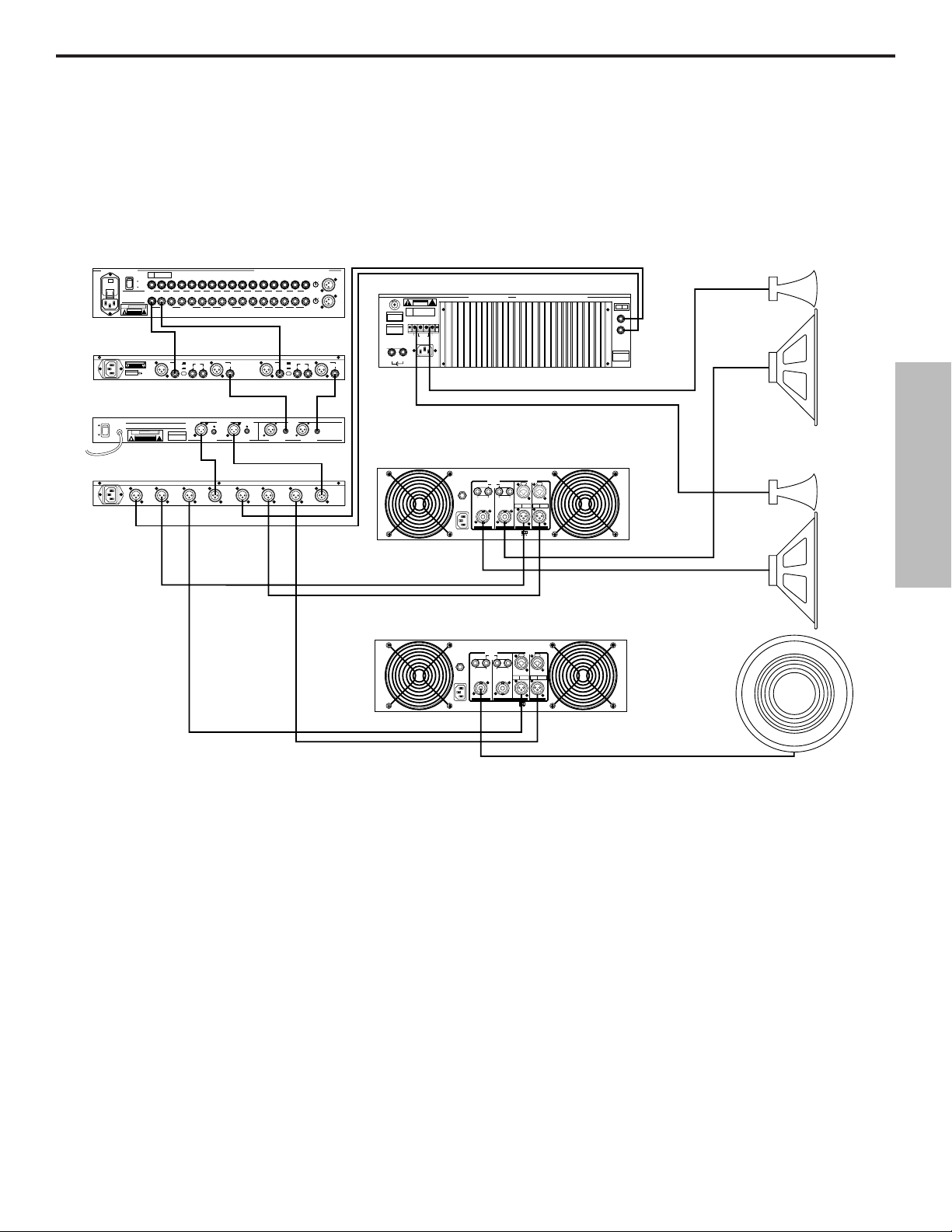
Configurations du système S•com
SYSTÈME DE SONORISATION DE SCÈNE AVEC COMPRESSION STÉRÉO
Dans cet exemple, le S•com est inséré après la console de mixage et avant l’égaliseur
graphique. Il compresse donc la totalité du signal provenant de la console.
29
FRANÇAIS
PL1602 M langeur
PL 1602
16 CHANNEL LINE MIXER
S / N
POWER
110
ON
OFF
AVIS:
RISQUE DE CHOC ELECTRIQUE
NE PAS OUVRIR
DO NOT EXPOSE THIS EQUIPMENT
TO RAIN OR MOISTURE
POWER
120V - 60 Hz 35W
RATING
CAUTION
RISK OF ELECTRIC SHOCK
~115V(0.3A)
230V(0.15A)
50/60Hz 30W
BALANCED 600 +4db
!
DO NOT OPEN
TIP + RING - SLEEVE GND
S¥Com
CAUTION
RISK OF ELECTRIC SHOCK
DO NOT OPEN.
2
SERIAL NUMBER
MADE IN CHINA
_ mA SLOW BLOW FUSE FOR 115V
_ mA SLOW BLOW FUSE FOR 220V
E30 Double galiseur 15 bandes
E30 2/3 OCTAVE STEREO 15 BAND GRAPHIC EQUALIZER
AVIS: RISQUE DE CHOC ELECTRIQUE NE PAS OUVRIR. DO NOT EXPOSE
THIS EQUIPMENT TO RAIN OR MOISTURE.
ON
~AC INPUT
POWER
120V - 60 Hz 20W
RATING
OFF
CAUTION
RISK OF ELECTRIC SHOCK
POWER
115V/230V 50/60Hz13W
S¥3 Way
!
DO NOT OPEN
CH 2
HIGH
OUTPUT
2
2
1
CH 2
HIGH
3
OUTPUT
MONO
HIGH
OUTPUT
INPUTS BALANCED 10KΩ -30 to +4db TIP + RING - SLEEVE GND.
AUX
BUS
RETURNS
INSERTS
MIXER LINKING
UNBALANCED 10KΩ
CHANNEL 2
+4
KEY
BALANCED
INPUT
-10
INPUT OUTPUT
2
1
3
SERIAL NUMBER
1
CH 2
3
OUTPUT
MONO
HIGH-MID
OUTPUT
1
LEVEL
3
BALANCED <100Ω
OUTPUTS
0db UNITY GAIN
BALANCED
<100KΩ 0db
UNITY GAIN
CH 2
LOW
OUTPUT
2
2
1
1
CH 2
LOW
MID
3
3
OUTPUT
2R
1L2R3L4RLRLR
1L
AUX SEND
UNBALANCED
2KΩ +4db
XLR
PIN 1 GND
BALANCED
PIN 2 HOT
OUTPUT
PIN 3 NEG
S com Plus
PHONE
TIP - POS
RING - NEG
SLEEVE - GND
BALANCED <100Ω
0db UNITY GAIN
<100KΩ 0db
UNITY GAIN
CH 2
INPUT
2
1
CH 2
INPUT
3
SAMSON TECHNOLOGIES CORP., NEW YORK, U.S.A.
1L2R3L4R5L6R7L8R9L10R11L12R13L14R15L16R
6R 5L 4R 3L 2R 1L
INSERTS TIP RETURN RING SEND
CHANNEL 1
+4
KEY
BALANCED
INPUT
INPUT
-10
OUTPUT
2
1
LEVEL
3
INPUTS
BALANCED
0db UNITY GAIN
BALANCED
BALANCED
10KΩ
CHANNEL ACHANNEL BCHANNEL ACHANNEL B
CH 1
HIGH
OUTPUT
CH 1
HIGH
OUTPUT
CH 1
LOW
OUTPUT
2
2
1
1
CH 1
CH 1
LOW
MID
3
3
OUTPUT
OUTPUT
MONO
MONO
LOW
LOW-MID
OUTPUT
OUTPUT
MIC 1
-10
2
3
0
1
-40+4
TRIM
-10
2
3
0
1
-40+4
TRIM
MIC 3MAIN OUT
BALANCED
OUTPUT
2
1
3
Servo 550 Amplificateur de puissance (Aigus)
CAUTION
RISK OF ELECTRIC SHOCK
DO NOT OPEN
F
E
U
S
SERIAL
FUSE
NUMBER
FUSE RATING
12A/250V (115V)
6A/250V (230V)
USE CLASS 2 WIRING MAXIMUM LOAD IMPEDANCE 4Ω
CAUTION
HEATSINK MAY BE
HOT! DO NOT BLOCK
AIRFLOW OR OVERHEATING MAY OCCUR
TO PREVENT SHOCK DO
GROUND
+RIGHT
NOT OPEN. NO USER
SERVICABLE PARTS
INSIDE. REFER SERVICING
TO QUALIFIED SERVICE
OUTPUT 250W/4Ω
PERSONNEL. TO PREVENT
FIRE OR SHOCK HAZARD
DO NOT EXPOSE TO RAIN
OR MOISTURE.
RIGHT
~AC INPUT
LEFT
115V/230W, 50/60HZ
510W (115V)900W (230V)
SERVO 550 STUDIO AMPLIFIER
!
LEFT+
SAMSON TECHNOLOGIES CORP., HICKSVILLE, NEW YORK
BRIDGED
TIP RING SLEEVE
SLEEVE GND
MONO STEREO
LEFT
RIGHT
INPUTS
(BALANCED
10KΩ/0dBm0)
TIP +
RING -
Gauche : Aigus/M diums
BALANCED
0db UNITY GAIN
BALANCED
10KΩ
SAMSON
TECHNOLOGIES
CORP.,
NEW YORK, U.S.A.
S1500 Amplificateur de puissance (M diums)
INPUT
115V 60Hz, 1100W
PUSH TO RESET
PUSH TO RESET
115V 60Hz, 920W
25A/250V
~AC INPUT
OUTPUT
20A/250V
(4Ω~8Ω) (4Ω~8Ω)
~AC INPUT
(4Ω~8Ω) (4Ω~8Ω)
CH 2 CH 1
OUTPUT
(4Ω~8Ω) (4Ω~8Ω)
(4Ω~8Ω) (4Ω~8Ω)
CH 2 CH 1
BALANCED
TRS
BALANCED
BRIDGED PARALLEL
BALANCED
0dBm
TRS
BALANCED
CH 2 CH 1
BRIDGED PARALLEL
0dBm
TIP=HOT
RING=COLD
SLEEVE=GND
CH 2 CH 1
STEREO
INPUT
TIP=HOT
RING=COLD
SLEEVE=GND
STEREO
BALANCED
0dBm
3=COLD
XLR
2=HOT
BALANCED
1=GND
BALANCED
0dBm
3=COLD
XLR
2=HOT
BALANCED
1=GND
MODE
CHANNEL
STEREO
1 INPUT
2 WAY
2
1
CHANNEL
STEREO
1 INPUT
3 WAY
3
MONO
MONO
INPUT
4 WAY
S2000 Amplificateur de puissance
(Bridg mono Graves)
Droite : Aigus/M diums
Sub
Mono
Page 31
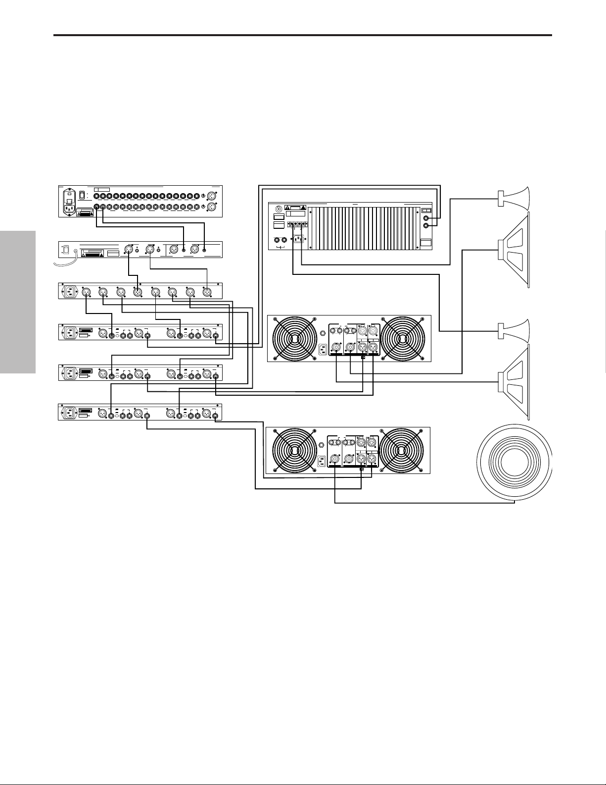
Configurations du système S•com
SYSTÈME DE SONORISATION LIVE AVEC COMPRESSION MULTIBANDE
Dans cet exemple, trois S•com sont insérés après la console de mixage, l’égaliseur et le filtre
actif, ce qui permet une compression individuelle des graves, médiums et aigus.
30
FRANÇAIS
PL1602 M langeur
PL 1602
16 CHANNEL LINE MIXER
S / N
POWER
110
ON
OFF
AVIS:
RISQUE DE CHOC ELECTRIQUE
NE PAS OUVRIR
DO NOT EXPOSE THIS EQUIPMENT
TO RAIN OR MOISTURE
POWER
120V - 60 Hz 35W
RATING
CAUTION
RISK OF ELECTRIC SHOCK
~115V(0.3A)
230V(0.15A)
50/60Hz 30W
E30 Double galiseur 15 bandes
E30 Dual 15 Band EQ
ON
OFF
POWER
S¥3 Way
BALANCED 600 +4db
!
DO NOT OPEN
TIP + RING - SLEEVE GND
E30 2/3 OCTAVE STEREO 15 BAND GRAPHIC EQUALIZER
AVIS: RISQUE DE CHOC ELECTRIQUE NE PAS OUVRIR. DO NOT EXPOSE
THIS EQUIPMENT TO RAIN OR MOISTURE.
~AC INPUT
POWER
120V - 60 Hz 20W
RATING
CAUTION
RISK OF ELECTRIC SHOCK
!
DO NOT OPEN
115V/230V 50/60Hz13W
CH 2
HIGH
OUTPUT
2
2
1
CH 2
HIGH
3
3
OUTPUT
MONO
HIGH
OUTPUT
S¥Com
CAUTION
RISK OF ELECTRIC SHOCK
DO NOT OPEN.
2
3
SERIAL NUMBER
MADE IN CHINA
_ mA SLOW BLOW FUSE FOR 115V
_ mA SLOW BLOW FUSE FOR 220V
S¥Com
CAUTION
RISK OF ELECTRIC SHOCK
DO NOT OPEN.
2
3
SERIAL NUMBER
MADE IN CHINA
_ mA SLOW BLOW FUSE FOR 115V
_ mA SLOW BLOW FUSE FOR 220V
INPUTS BALANCED 10KΩ -30 to +4db TIP + RING - SLEEVE GND.
AUX
BUS
RETURNS
INSERTS
MIXER LINKING
UNBALANCED 10KΩ
BALANCED <100Ω
OUTPUTS
0db UNITY GAIN
BALANCED
<100KΩ 0db
UNITY GAIN
SERIAL NUMBER
CH 2
LOW
OUTPUT
2
2
1
1
1
CH 2
CH 2
LOW
MID
3
3
OUTPUT
OUTPUT
MONO
HIGH-MID
OUTPUT
CHANNEL 2
+4
KEY
BALANCED
INPUT
-10
INPUT OUTPUT
2
1
BALANCED
INPUT
1
1
LEVEL
3
CHANNEL 2
+4
KEY
-10
INPUT OUTPUT
2
1
LEVEL
3
S¥Com
CHANNEL 2
+4
KEY
BALANCED
CAUTION
INPUT
RISK OF ELECTRIC SHOCK
DO NOT OPEN.
SERIAL NUMBER
MADE IN CHINA
_ mA SLOW BLOW FUSE FOR 115V
_ mA SLOW BLOW FUSE FOR 220V
-10
INPUT OUTPUT
2
1
3
2
1
LEVEL
3
2R
1L2R3L4RLRLR
1L
AUX SEND
UNBALANCED
2KΩ +4db
BALANCED <100Ω
0db UNITY GAIN
<100KΩ 0db
UNITY GAIN
CH 2
INPUT
2
1
CH 2
INPUT
3
XLR
PIN 1 GND
BALANCED
PIN 2 HOT
OUTPUT
PIN 3 NEG
S com
PHONE
TIP - POS
RING - NEG
SLEEVE - GND
XLR
PIN 1 GND
BALANCED
PIN 2 HOT
OUTPUT
PIN 3 NEG
S com
PHONE
TIP - POS
RING - NEG
SLEEVE - GND
XLR
PIN 1 GND
BALANCED
PIN 2 HOT
OUTPUT
PIN 3 NEG
S com
PHONE
TIP - POS
RING - NEG
SLEEVE - GND
SAMSON TECHNOLOGIES CORP., NEW YORK, U.S.A.
1L2R3L4R5L6R7L8R9L10R11L12R13L14R15L16R
6R 5L 4R 3L 2R 1L
INSERTS TIP RETURN RING SEND
INPUTS
BALANCED
0db UNITY GAIN
BALANCED
BALANCED
10KΩ
CHANNEL ACHANNEL BCHANNEL ACHANNEL B
CH 1
HIGH
OUTPUT
CH 1
HIGH
OUTPUT
CH 1
LOW
OUTPUT
2
2
1
1
CH 1
CH 1
LOW
MID
3
3
OUTPUT
OUTPUT
MONO
MONO
LOW
LOW-MID
OUTPUT
OUTPUT
CHANNEL 1
+4
KEY
BALANCED
INPUT
INPUT
-10
OUTPUT
2
1
LEVEL
3
CHANNEL 1
+4
KEY
BALANCED
INPUT
INPUT
-10
OUTPUT
2
1
LEVEL
3
CHANNEL 1
+4
KEY
BALANCED
INPUT
INPUT
-10
OUTPUT
2
1
LEVEL
3
MIC 1
-10
2
3
0
1
-40+4
TRIM
-10
2
3
0
1
-40+4
TRIM
MIC 3MAIN OUT
BALANCED
0db UNITY GAIN
BALANCED
10KΩ
SAMSON
TECHNOLOGIES
CORP.,
NEW YORK, U.S.A.
MODE
CHANNEL
STEREO
1 INPUT
2 WAY
2
1
CHANNEL
STEREO
1 INPUT
3 WAY
3
MONO
MONO
INPUT
4 WAY
Servo 550 Amplificateur de puissance (Aigus)
CAUTION
RISK OF ELECTRIC SHOCK
DO NOT OPEN
F
E
U
S
SERIAL
FUSE
NUMBER
FUSE RATING
12A/250V (115V)
6A/250V (230V)
USE CLASS 2 WIRING MAXIMUM LOAD IMPEDANCE 4Ω
CAUTION
HEATSINK MAY BE
HOT! DO NOT BLOCK
AIRFLOW OR OVERHEATING MAY OCCUR
TO PREVENT SHOCK DO
GROUND
+RIGHT
NOT OPEN. NO USER
SERVICABLE PARTS
INSIDE. REFER SERVICING
TO QUALIFIED SERVICE
OUTPUT 250W/4Ω
PERSONNEL. TO PREVENT
FIRE OR SHOCK HAZARD
DO NOT EXPOSE TO RAIN
OR MOISTURE.
RIGHT
~AC INPUT
LEFT
115V/230W, 50/60HZ
510W (115V)900W (230V)
SERVO 550 STUDIO AMPLIFIER
!
LEFT+
SAMSON TECHNOLOGIES CORP., HICKSVILLE, NEW YORK
BRIDGED
MONO STEREO
TIP RING SLEEVE
SLEEVE GND
LEFT
RIGHT
INPUTS
(BALANCED
10KΩ/0dBm0)
TIP +
RING -
S1500 Amplificateur de puissance (M diums)
INPUT
OUTPUT
PUSH TO RESET
PUSH TO RESET
115V 60Hz, 1100W
115V 60Hz, 920W
~AC INPUT
20A/250V
(4Ω~8Ω) (4Ω~8Ω)
~AC INPUT
(4Ω~8Ω) (4Ω~8Ω)
CH 2 CH 1
OUTPUT
25A/250V
(4Ω~8Ω) (4Ω~8Ω)
(4Ω~8Ω) (4Ω~8Ω)
CH 2 CH 1
BALANCED
TRS
BALANCED
BRIDGED PARALLEL
BALANCED
0dBm
TRS
BALANCED
CH 2 CH 1
BRIDGED PARALLEL
0dBm
TIP=HOT
RING=COLD
SLEEVE=GND
CH 2 CH 1
STEREO
INPUT
TIP=HOT
RING=COLD
SLEEVE=GND
STEREO
BALANCED
0dBm
3=COLD
XLR
2=HOT
BALANCED
1=GND
BALANCED
0dBm
3=COLD
XLR
2=HOT
BALANCED
1=GND
BALANCED
OUTPUT
2
1
3
BALANCED
OUTPUT
2
1
3
BALANCED
OUTPUT
2
1
3
S2000 Amplificateur de puissance
(Bridg mono Graves)
Gauche : Aigus/M diums
Droite : Aigus/M diums
Sub
Mono
Page 32
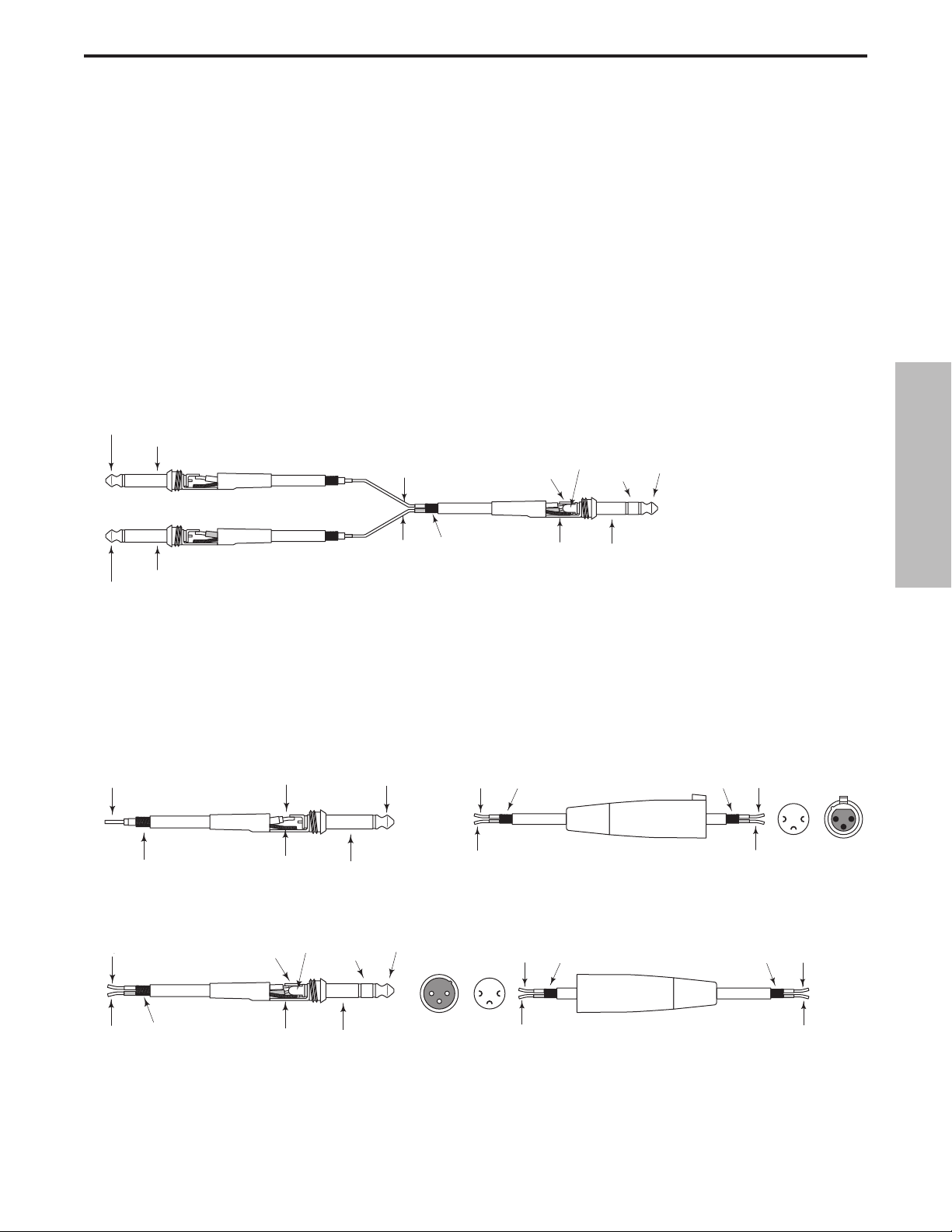
Connexions du S•com
Jack 6,35 mm asymétrique
Câble d’insertion en configuration départ/retour
sur Jack stéréo 6,35 mm/deux Jacks 6,35 mm.
Guide de câblage pour connecteur XLR symétrique
CONNEXION DU S•com
Il existe plusieurs façons d’intégrer le S•com à différentes applications. Le S•com est équipé d’entrées/sorties à
symétrie électronique. Ainsi, la connexion de signaux symétriques et asymétriques peut se faire sans perte de signal.
Le S•com peut être relié à un seul instrument, en le connectant aux points d’insertion d’un canal, ou à un système de
mixage complet, entre les sorties d’une console et un amplificateur de puissance ou un égaliseur.
POINTS D’INSERTION
Aujourd’hui, de nombreuses consoles de mixage sont équipées d’insertions de voie et d’insertions de bus ou de
groupe. Les points d’insertion sont constitués d’une entrée/sortie qui coupe le signal du bus ou de la voie et permet de
connecter des processeurs externes. Les points d’insertion de voie conviennent parfaitement à la connexion du
S•com afin de traiter une seule voie (chant, basse ou guitare). Les insertions de bus sont parfaitement adaptées à la
compression de groupes d’instruments, comme les chants, les cordes ou la batterie. Pour la connexion à des insertions de voies, il se peut que vous ne disposier que d’un seul Jack stéréo pour le départ et le retour. Dans ce cas,
utilisez un câble en "Y", câblé comme dans le schéma ci-dessous
.
En ligne
En application live, le S•com peut être installé “en ligne” entre une console de mixage et un égaliseur ou un
ampli de puissance. Pour ces applications, le S•com est équipé de Jacks stéréo 6,35 mm et de connecteurs
XLR, lui permettant de se relier à pratiquement tous les appareils audio professionnels. Adaptez les exemples
de câblage ci-dessous à votre installation.
Jack stéréo 6,35 mm symétrique
31
FRANÇAIS
Pointe (départ)
Corps (commun)
Pointe (retour)
Corps (commun)
Départ (pointe)
Retour (bague)
Commun
Retour (bague)
Départ (pointe)
Commun
Corps (commun)
Bague (retour)
Pointe (départ)
Signal
Masse
Masse
Pointe (signal)Signal
Corps (masse)
Point chaud
Point froid
XLR femelle
Point chaud (2)
Commun (1)Commun
1
2
3
Point froid (3)
Points de
soudure
Vue finale
21
3
Signal (pointe)
Signal (bague)
Masse
Signal (bague)
Signal (pointe)
Masse
Bague (signal)
Corps (masse)
Pointe (signal)
12
Vue finale Points de
2
3
3
soudure
Point chaud (2)
1
Point froid (3)
Commun (1) Commun
XLR mâle
Point chaud
Point froid
Page 33

Vorwort von Ray Kennedy
Kompressoren und Limiter zählen bei der Aufnahme und Mischung zu den wichtigsten verfügbaren
Tools und sind viel nützlicher, als man glaubt. Für mich ist Kompression eher ein Sound als ein Gerät
zur Dynamiksteuerung. Da jedes Modell einen eigenen Klang und idealen Anwendungsbereich besitzt,
arbeite ich mit einer Auswahl von etwa 40 eigenen Kompressoren. Um herauszufinden, welcher
Gerätetyp mit welchen Einstellungen im Einzelfall optimal geeignet ist, bedarf es vieler Versuche und
Experimente – aber mit der Zeit werden Sie die besten Anwendungen finden.
Peak Limiting und Soft Compression eignen sich normalerweise gut für das Maximieren von Pegeln
für Band oder CD, ohne den Klang zu stark zu verfärben. Prinzipiell werden die Pegelspitzen gekappt
und die leiseren Bestandteile eines Klangs angehoben, indem man den Dynamikbereich einengt. Lange
Attack- und kurze Release-Zeiten ermöglichen einen transparenteren Klang. Ich persönlich mag den
Sound der Kompression und nutze ihn machmal extrem ausgeprägt. Abhängig von Gerätetyp und
Einstellungen lassen sich ganz unterschiedliche Klangfarben kreieren, von Verdichtung und Raumklang
über die Erhöhung/Verringerung des klanglichen Kontrastes bis hin zur EQ-Bearbeitung und vieles
mehr. Mein bevorzugter 'Manic Compression‘ Trick lässt den Gesang praktisch über der Mischung
schweben, trocken und nah, aber nicht zu laut, als ob der Sänger direkt vor mir steht.Mein Partner Steve
Earle sagt, wir benutzen bei seinen Platten so viel Kompression für den Gesang, dass die Leute sogar
merken, was er zum Frühstück gegessen hat.
Häufig dient Kompression als Ersatz für Reverb und kann bei extremem Einsatz den ganzen
Raumklang im Umfeld des Gesangmikros „absaugen“ und subtile Klangnuancen in den Tiefen der
Stimmbänder offenbaren. Bei einem Overhead- oder Raummikrofon können Sie sogar die
wahrgenommene Raumgröße ändern, indem Sie den abklingenden, sich entfernenden Sound
wieder zurückziehen. Wiederum erzielen Sie mit langen Attack- und kurzen Release-Zeiten die
besten Ergebnisse, da Sie den Schwellwert viel härter ansteuern können.
Indem Sie Limiting und Kompression auf den Stereo-Bus anwenden, können Sie auch sehr effektiv Spuren verschmelzen und Bands kompakter klingen lassen, als sie tatsächlich sind. Diese
Methode ermöglicht auch mehr Sättigung im analogen 2-Spur-Format sowie eine vollere
Modulation bei digitalen Formaten. Für mich ist es fast normal, beim Mastering der endgültigen
Songversion auf Festplatte drei Stereo-Limiter vorzuschalten.
Häufig können Sie durch das Bearbeiten eines Signals mit mehreren Kompressoren interessante
Ergebnisse erzielen, die mit nur einem Gerät nicht erreichbar wären. Es gibt zwar keine festen
Regeln, aber Sie sollten wissen, dass es in puncto Komprimierung viele verschiedene Konzepte
gibt. Manche basieren völlig auf Röhren, andere auf Röhren und optischen Verfahren, wieder
andere sind rein optisch orientiert, und außerdem gibt es da noch FET Transistoren, VCAs (Voltage
Control Amplifiers) Pure Class A, Class A/B, Digital sowie weitere Kombinationen.
Wir sind jetzt endlich in einem Zeitalter sehr hochwertiger VCAs angekommen, die nicht mehr so
teuer sind und sehr komplexe und vielseitige Schaltungskonzepte ermöglichen – wie die S-Class
Geräte von Samson.
Ray Kennedy
Ray Kennedy lebt in Nashville und arbeitet als Produzent,
Tontechniker und Komponist. Seine Produktionsfirma Twang
Trust, eine Kooperation zwischen Ray und Singer/Songwriter
Steve Earle, hat sehr bekannte Aufnahmen und Darbietungen
von Künstlern wie Steve Earle, Art Garfunkel, Willie and
Waylon, Farm Aid, The Del McCoury Band, Nancy Griffith,
Lucinda Williams, David Alan Coe, Shaver, V-Roys und Rosie
Flores hervorgebracht.
32
DEUTSCHE
Page 34
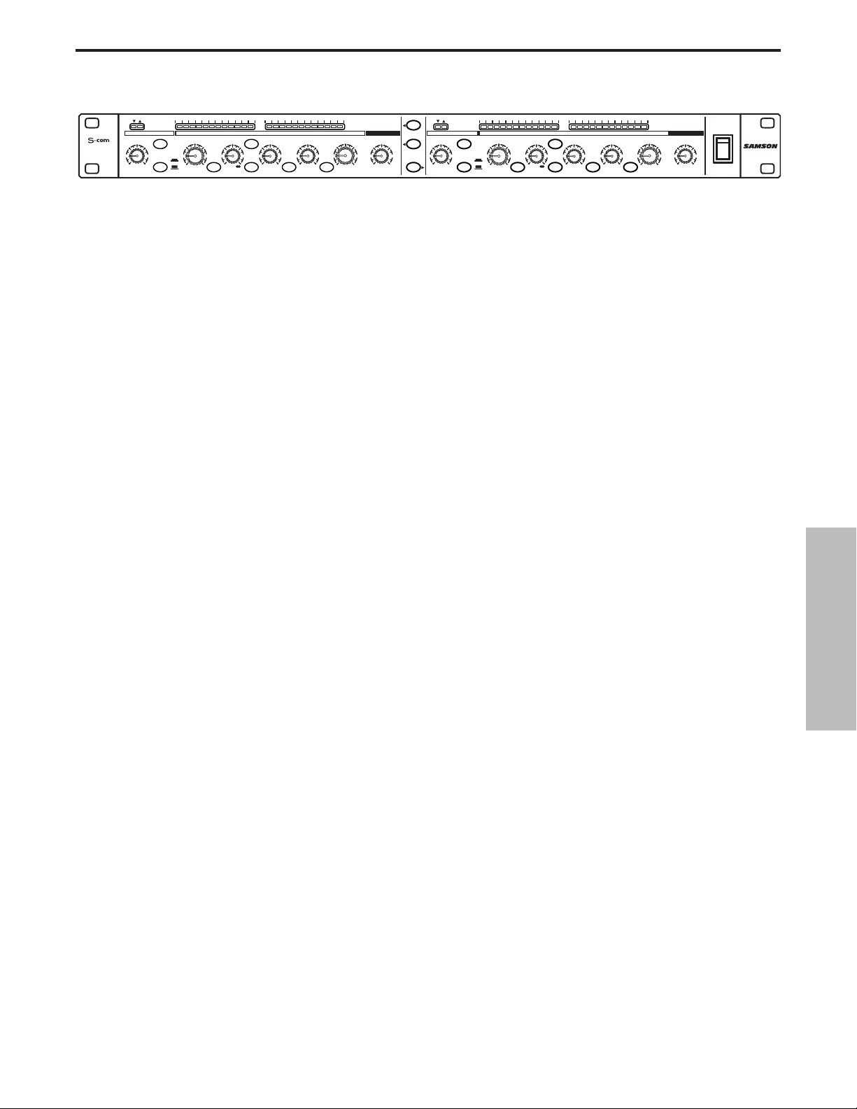
S•com Features
Der Samson S com Dynamikprozessor verwendet modernste Gain Management-Technologie. Hier die
Hauptfunktionen:
• Voll ausgestatteter, 2-kanaliger Dynamikprozessor mit Compressor/Limiter, Expander/Gate, De-Esser
und Peak Limiter.
• SKD (Smart Knee Detector) schaltet – basierend auf dem Pegel des Eingangssignals – zwischen Soft
Knee- und Hard Knee-Kompression um.
• AEG (Automatic Envelope Generator) Modus regelt ständig die Attack- und Release-Zeiten des Kompressors,
basierend auf dem Eingangssignal. Manuelles Einstellen der Attack und Release-Zeiten ist ebenfalls möglich.
• 12 segmentige Input/Output LED-Anzeige plus 12-segmentige Gain Reduction LED-Anzeige.
• Externe Key-Steuerung mit vorderseitigem Key Listen-Schalter.
• Regelbarer Enhancer zum Wiederherstellen der Höhen, die durch starke Gain-Reduzierung verloren gingen.
• Expander/Gate mit variabler Threshold-Regelung und schaltbarer Fast/Slow Release-Zeit.
• Gate-Funktion schaltbar von „hartem Aus“ auf leichten Downward Expander.
• LEDs für zur Anzeige des geöffneten/geschlossen Gates.
• Spectra-Schaltung zum Entfernen von Zischlauten durch Anpassen des Mitten/Höhenbereichs.
• Fortschrittliche Schaltungskonstruktion mit rauscharmen Operationsverstärkern und hochwertigen VCAs.
• Stereo Link-Taste.
• Servo-symmetrische Eingänge und Ausgänge bei den XLR und 1/4” Anschlüssen.
• Schaltbare Betriebspegel von +4 und –10.
• Hochwertige, auf 41 Positionen einrastende Potentiometer und hintergrundbeleuchtete Tasten.
• Das modische, perlentexturierte, anodisierte vorderseitige Bedienfeld in Elektro-Blau ist gut lesbar und
sieht toll aus.
• 3-jährige erweiterte Garantie.
33
DEUTSCHE
STEREO
COMPRESSOR
GAIN REDUCTION dB INPUT / OUTPUT LEVEL dB
30 24 2127 18 15 9 612 4 2 1 -30 -18 -12-24 -6 -3 +3 +60 +9 +12+18
THRESHOLDTRIGGER RATIO ATTACK RELEASE OUTPUT ENHANCER
-10
10
GATE KEY
-30
FAST
+20-40
SLOW
dB
RELEASE SPECTRA KEY AUTO I/O METER
OFF +10
20
050
dB
COMPRESSOR / LIMITEREXPANDER/GATE
4:1
50
LISTEN
62
+10
.3 300
1
dB
mSec
OFF 10
STEREO LINK
IN/OUT 1
IN/OUT 2
20
GATE
GATE KEY
050
OFF +10
dB
RELEASE
5
73
0
1
20015
3.15
-10
.05 5
Sec
+10
+20-20
dB
GAIN REDUCTION dB INPUT / OUTPUT LEVEL dB
30 24 2127 18 15 9 612 4 2 1 -30 -18 -12-24 -6 -3 +3 +60 +9 +12+18
THRESHOLDTRIGGER RATIO ATTACK RELEASE OUTPUT ENHANCER
-10
10
-30
FAST
+20-40
SLOW
dB
COMPRESSOR / LIMITEREXPANDER/GATE
4:1
50
LISTEN
62
+10
SPECTRA KEY AUTO I/O METER
.3 300
1
dB
1
20015
3.15
.05 5
mSec
Sec
Sec
0
-10
+10
+20-20
dB
CH 2
CH 2CH 1
OFF 10
POWER
5
73
Page 35
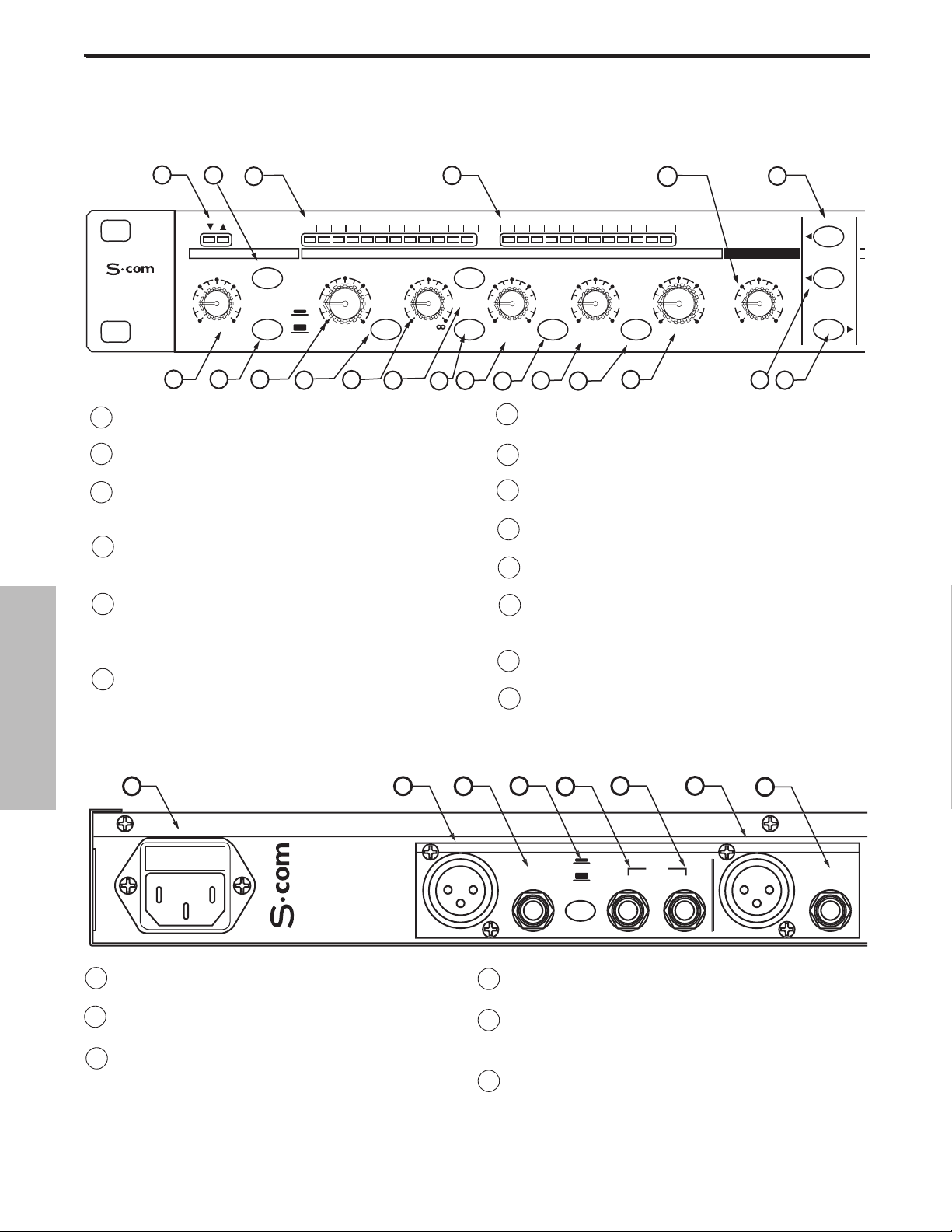
6
A ANETZANSCHLUSS - IEC standard
Wechselstrom-Anschluss für ein Netzkabel.
B CHANNEL 2 XLR-EINGANG - symmetrischer
XLR Line-Eingang.
C CHANNEL 2 1/4”STEREO-EINGANG - sym-
metrischer 1/4” Klinken Line-Eingang.
D BETRIEBSPEGEL-SCHALTER - Schaltet den
Betriebspegel zwischen –10 dB und +4 dB um.
E CHANNEL 2 KEY-EINGANG - Eingang zur exter-
nen Steuerung der S•com KompressorDetektorschaltung.
F CHANNEL 1 KEY-AUSGANG - Send-Weg der
S•com Detektorschaltung.Via Key-Ausgang können Sie die Detektorschaltung des Kompressors
mit einem externen Effekt, beispielsweise einem
Equalizer, bearbeiten.
1 GATE OPEN & CLOSED LED - Zeigt an,wann das Gate
geöffnet oder geschlossen ist.
2 GATE SCHALTER - Wählt den Gate- oder Expander-
Modus.
3 GAIN REDUCTION-ANZEIGE - Zeigt die Stärke der
Gain-Reduzierung bei aktivierter KompressorSchaltung an.
4 INPUT/OUTPUT-ANZEIGE - Zeigt den Eingangs- oder
Ausgangs-Signalpegel basierend auf der Einstellung
der I/O Anzeige-Taste an.
5 ENHANCE- Stellt den Pegel der S•com Enhanced
Spectrum Recovery-Schaltung ein, welche die durch
extreme Gain-Reduzierung verloren gegangenen
Höhen wiederherstellt.
6 STEREO LINK-TASTE - Bei gedrückter Taste werden
die Kanal 2-Funktionen von den Kanal 1Einstellungen gesteuert.
0
7 CHANNEL 2-REGLER - Die gleiche Regler- und
Schaltungsfamilie wie bei Kanal.
8 POWER-SCHALTER -
Schaltet den S•com
ein/aus.
9 RACK-ÖSEN - Zum Einbau des S•com in ein stan-
dard 19“ Rack.
10 TRIGGER- Zum Einbau des S•com in ein standard
19“ Rack.
11 RELEASE-TASTE – Zur Wahl der Release-Zeit FAST
oder SLOW für EXPANDER/GATE.
12 THRESHOLD - Damit stellen Sie den Mindest-
Signalpegel ein, ab dem die Kompressor-Schaltung
zu arbeiten beginnt.
13 SPECTRA-TASTE - Aktiviert die S•com SPECTRA-
Schaltung zur Höhen-Anpassung.
14 RATIO - Steuert die Stärke der Gain-Reduzierung
im Verhältnis zur Stärke des über dem gewählten
Schwellwert liegenden Signals.
D
OUTPUT
D
UT
UT
OUTPUT
CHANNEL 2
0
34
DEUTSCHE
Regler und Funktionen
RÜCKSEITE
VORDERSEITE
1
STEREO
COMPRESSOR
10
A
2
20
OFF +10
dB
11
3
30 24 2127 18 15 9 612 4 2 1 -30 -18 -12-24 -6 -3 +3 +60 +9 +12 +18
GATE KEY
050
FAST
SLOW
RELEASE SPECTRA KEY AUTO I/O METER
12
13
GAIN REDUCTION dB INPUT / OUTPUT LEVEL dB
THRESHOLDTRIGGER RATIO ATTACK RELEASE OUTPUT ENHANCER
10
-10
-30
+10
+20-40
dB
14
15
4
COMPRESSOR / LIMITEREXPANDER/GATE
4:1
LISTEN
62
1
dB
17
16
50
.3 300
mSec
18
20015
19
.05 5
20
1
3.15
Sec
B
C
D
E
F G
21
5
0
-10
+10
+20-20
dB
CH 1
5
OFF 10
22
H
6
73
23
STEREO LINK
IN/OUT 1
IN/OUT 2
5
BALANCE
INP
-1
INP
BALANCE
Page 36
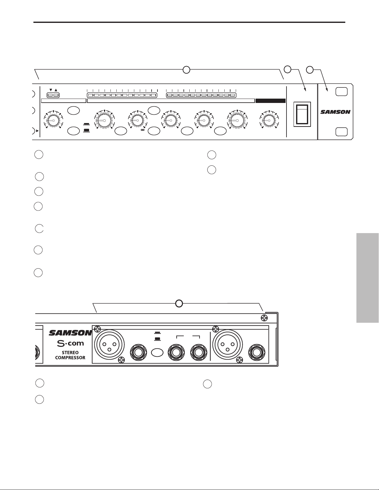
G KANAL 2 XLR AUSGANG - symmetrischer XLR
Line-Ausgang.
H KANAL 2 1/4” KLINKEN AUSGANG - symmetrisch-
er 1/4” Klinken Line-Ausgang.
I KANAL 1 - die gleichen Eingänge und
Ausgänge wie Kanal 2.
15 KEY LISTEN-TASTE- Bei gedrückter Taste wird das am
KEY INPUT anliegende Signal direkt zum Kanalausgang
geleitet.
16 KEY-TASTE - Wählt den Key-Eingang, damit ein externes
Signal den Kompressor triggern kann.
17 ATTACK - Regelt die Zeitspanne, die der Kompressor bis
zum Erreichen der vollen Gain-Reduzierung benötigt.
18 AUTO - Aktiviert die S•com AEG-Funktion (Auto
Envelope Generator), die – basierend auf dem Signalgehalt – die Attack- und Release-Zeit dynamisch regelt.
19 RELEASE - Regelt die Zeitspanne, die der Kompressor
benötigt, um das Signal auf seinen ursprünglichen Pegel
zurückzusetzen.
20 INPUT/ OUTPUT ANZEIGE-WAHLTASTE - Damit kön-
nen Sie wählen, ob der Eingangs- oder Ausgangs-pegel
auf der Input/Output-Anzeige angegeben wird.
21 LEVEL - Regelt die Höhe des Ausgangspegelsl.
22 CHANNEL 1 IN/OUT-TASTE- Aktiviert Kanal 1
des S•com.
23 CHANNEL 2 IN/OUT-TASTE - Aktiviert Kanal
2 des S•com.
D
D
OUTPUT
D
UT
UT
OUTPUT
C
1
0
35
DEUTSCHE
Regler und Funktionen
GAIN REDUCTION dB INPUT / OUTPUT LEVEL dB
THRESHOLDTRIGGER RATIO ATTACK RELEASE OUTPUT ENHANCER
-10
10
-30
+10
+20-40
dB
SPECTRA KEY AUTO I/O METER
COMPRESSOR / LIMITEREXPANDER/GATE
4:1
LISTEN
62
1
dB
50
.3 300
mSec
20015
LINK
1
2
20
OFF +10
dB
30 24 2127 18 15 9 612 4 2 1 -30 -18 -12-24 -6 -3 +3 +60 +9 +12 +18
GATE KEY
GATE
050
RELEASE
FAST
SLOW
7
CH 2
CH 2
1
.05 5
Sec
Sec
3.15
0
-10
+10
+20-20
dB
OFF 10
8
5
73
POWER
POWER
9
I
HANNEL
E
BALANCE
INP
-1
INP
BALANCE
Page 37
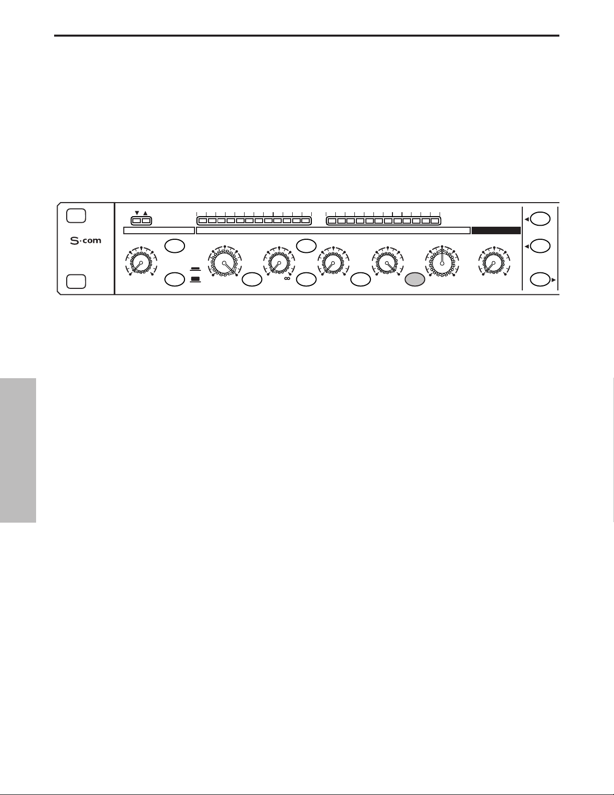
S•com bedienen
Gleichgültig ob Sie ein erfahrener Tontechniker sind oder sich gerade in die Materie einarbeiten oder einfach
experimentieren möchten, gehen Sie anfänglich wie unten beschrieben vor. Kommende Abschnitte dieses
Handbuchs befassen sich mit Dynamik-Grundlagen und den zugehörigen Parametern, Systemeinrichtungen
sowie Anwendungsmöglichkeiten für die Dynamikbearbeitung bei Aufnahmen und Live-Beschallungen.
S•com EINRICHTEN
• Verbinden Sie ein oder beide Eingangs- und Ausgangspaare mit den entsprechenden rückseitigen Anschlüssen.
• Stellen Sie die Regler wie folgt ein:
In dieser Konfiguration gibt der S•com Audiosignale mit Unity Gain – also ohne Dynamikbearbeitung – aus. Jetzt
ist eine gute Gelegenheit, um die Verstärkungsstruktur zu überprüfen. Passen Sie die Pegel mit der
Input/Output-Anzeige an.
Leiten Sie ein Signal zu einem oder beiden Ein- und Ausgängen des S•com.
• Drücken Sie die METER-Taste, um festzustellen, ob die Eingangs- und Ausgangspegel abgestimmt sind.
SIGNAL KOMPRIMIEREN
Die Kompressor-Sektion des S•com lässt sich für eine Vielzahl von Gain Management-Aufgaben einsetzen. Zum
Beispiel bei der Signalausgabe zu einem Mehrspur-Recorder oder als Effekt beim Abmischen/Mastering sowie
zur Erhöhung der Lautheit eines live PA-Systems. Um mit dem Komprimieren des Signals zu beginnen, gehen
Sie wie folgt vor:
• Gehen Sie nach dem obigen Abschnitt “S•com EINRICHTEN” vor, um die Regler zurückzusetzen.
• Setzen Sie die CHANNEL IN-Taste (in der Mitte des Geräts) auf die IN-Position.
• Drücken Sie die AUTO-Taste (zwischen ATTACK und RELEASE).
• Setzen Sie Ratio auf 2:1.
EXPANDER/GATE TRIGGER – OFF
GATE-TASTE – GELÖST
FAST RELEASE – GELÖST
COMPRESSOR THRESHOLD – +20 dBu (ganz nach rechts)
SPECTRA - GELÖST
RATIO – 1:1
KEY-TASTE - GELÖST
AT TAC K – 0.3 (ganz nach links)
AUTO-TASTE - GELÖST
RELEASE -5 (ganz nach rechts)
METER-TASTE – GEDRÜCKT
OUTPUT LEVEL – O dBu
ENHANCER – OFF (ganz nach links)
STEREO LINK-TASTE – GELÖST
CHANNEL 1 ENGAGE – GELÖST
36
DEUTSCHE
30 24 2127 18 15 9 612 4 2 1 -30 -18 -12-24 -6 -3 +3 +60 +9 +12 +18
STEREO
COMPRESSOR
20
OFF +10
dB
GATE KEY
050
FAST
SLOW
RELEASE SPECTRA KEY AUTO I/O METER
GAIN REDUCTION dB INPUT / OUTPUT LEVEL dB
THRESHOLDTRIGGER RATIO ATTACK RELEASE OUTPUT ENHANCER
-10
10
-30
+10
+20-40
dB
COMPRESSOR / LIMITEREXPANDER/GATE
-10
0
+10
+20-20
dB
4:1
LISTEN
62
1
dB
50
.3 300
mSec
1
20015
.05 5
Sec
3.15
CH 1
OFF 10
STEREO LINK
5
IN/OUT 1
73
IN/OUT 2
Page 38
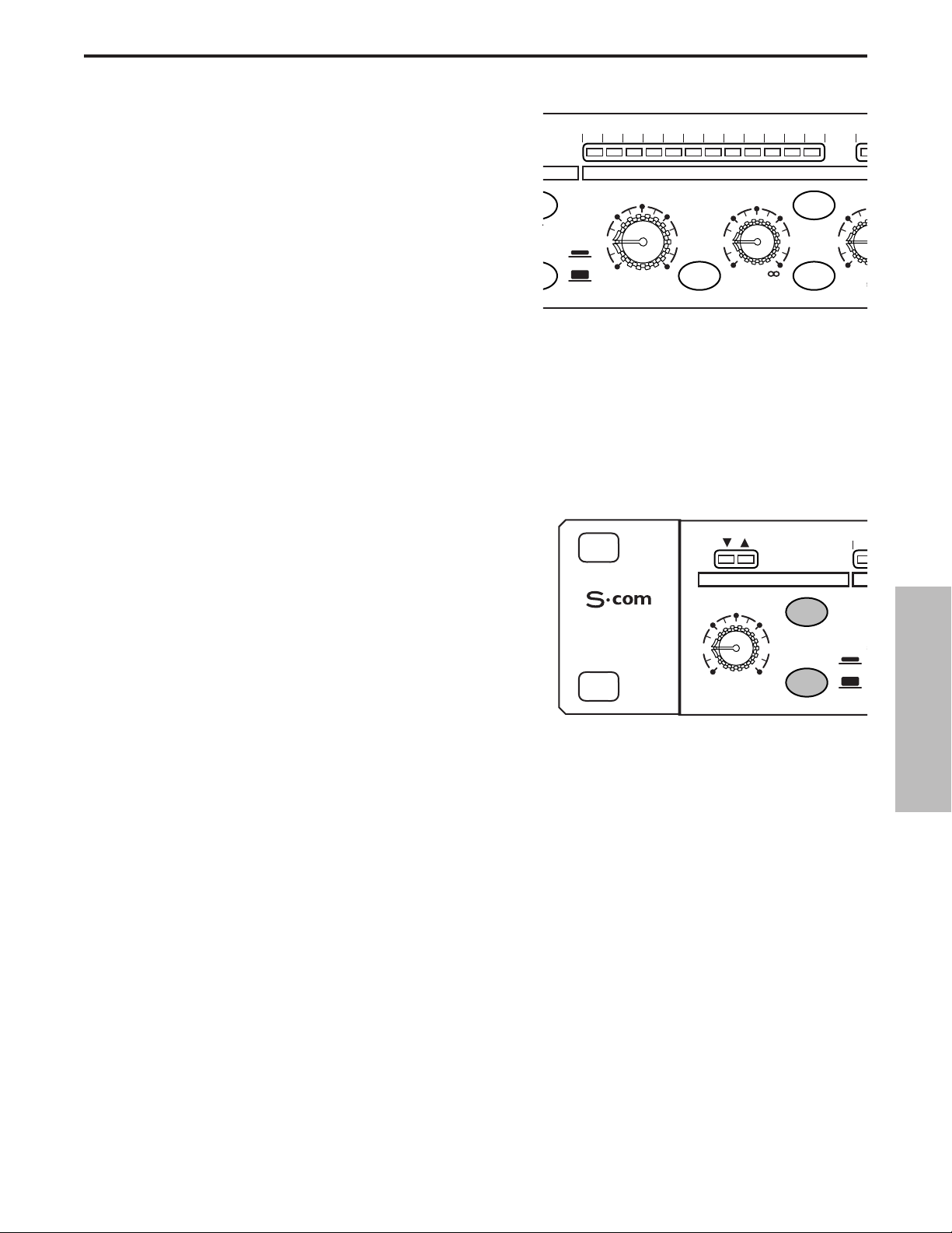
S•com bedienen
• Drehen Sie jetzt den THRESHOLD-Pegel langsam
zurück und achten Sie auf die Kompression. Optisch
wird die Kompressionsstärke auf der GAIN
REDUCTION-Anzeige dargestellt.
• Lösen Sie die AUTO-Taste, um mit manuell gesteuerten
ATTACK- und RELEASE-Zeiten zu experimentieren.
OT
S
5
T
SIGNAL GATEN
Unerwünschte Stör-, Brumm und Zischgeräusche lassen sich problemlos mit dem S•com GATE entfernen. Ziel
ist es, das Gate nur so lange zu öffnen, wie das gewünschte Signal erklingt, und in den Pausen unerwünschte
Stör-, Brumm und Zischgeräusche stumm zu schalten (Gate geschlossen). Um das Signal zu gaten, gehen Sie
wie folgt vor:
• Gehen Sie nach dem obigen Abschnitt “S•com EINRICHTEN” vor, um die Regler zurückzusetzen.
• Um das Gate zu aktivieren, stellen Sie sicher, dass die EXPANDER/GATE-Taste gedrückt ist.
0
3
• Setzen Sie die RELEASE-Taste auf die IN-Position, um
die Release-Zeit FAST zu wählen.
• Erhöhen Sie jetzt den THRESHOLD-Pegel und achten
Sie darauf, wie die Gate-Funktion auf das Signal zu
wirken beginnt. Eine optische Darstellung des sich öffnenden und schließenden Gates bieten die GATE
OPEN/CLOSED LEDs über dem EXPANDER/GATE
TRIGGER-Regler.
DOWNWARD EXPANDER EINSETZEN
Sie können die Gate-Sektion des S•com so einstellen, dass sie wie ein DOWNWARD EXPANDER funktioniert,
um den Pegel eines Signals zu verringern. Gehen Sie einfach wie folgt vor:
• Gehen Sie nach dem obigen Abschnitt “S•com EINRICHTEN” vor, um die Regler zurückzusetzen.
• Um den EXPANDER zu aktivieren, stellen Sie sicher, dass die EXPANDER/GATE-Taste GELÖST ist.
• Lösen Sie die RELEASE-Taste, um das RELEASE auf SLOW einzustellen.
• Erhöhen Sie jetzt den TRIGGER-Pegel, und achten Sie darauf, wie das Signal leiser wird.
37
DEUTSCHE
30 24 2127 18 15 9 612 4 2 1 -3
E
E KEY
-30
FAST
SLOW
SE SPECTRA KEY
GAIN REDUCTION dB
THRESHOLD RATIO AT
-10
10
+10
dB
+20-40
1
4:1
dB
COMPRESS
LISTEN
62
15
.3
m
3
STEREO
COMPRESSOR
EXPANDER/GATE
TRIGGER
20
GATE
050
OFF +10
dB
RELEASE
-
FAST
SLOW
Page 39
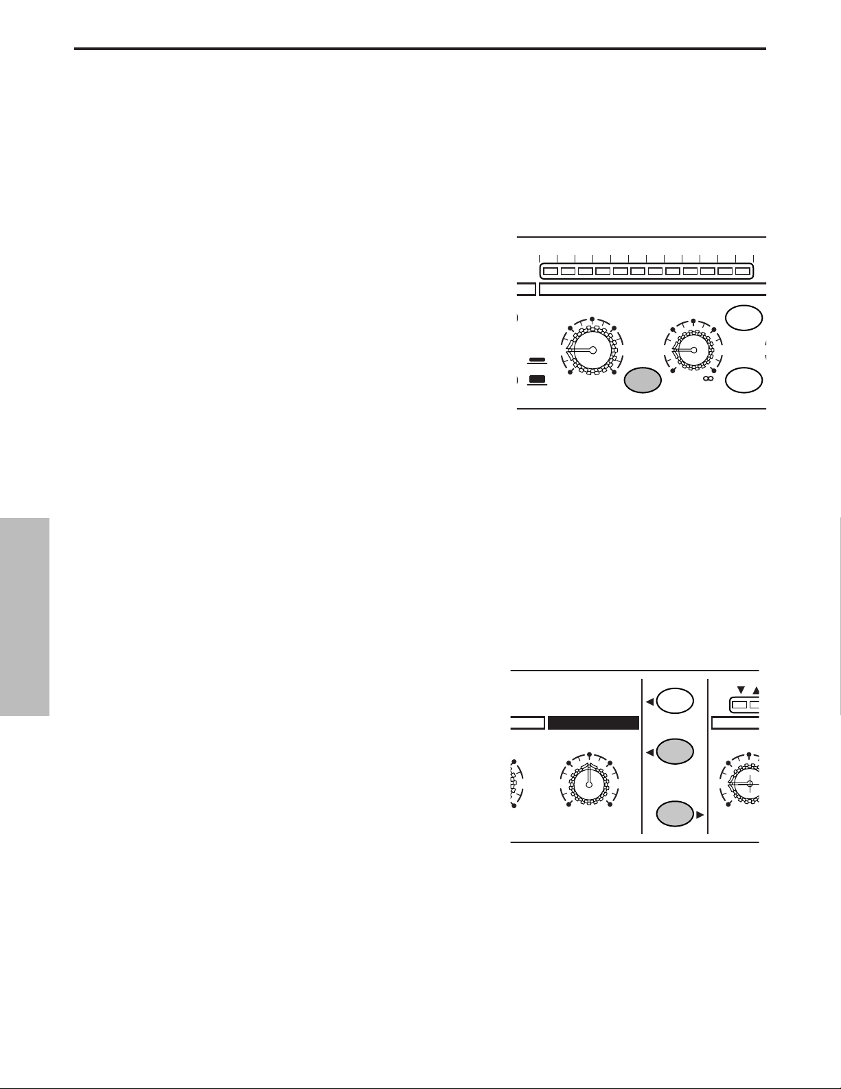
S•com bedienen
ENHANCER EINSETZEN
Mit der ENHANCER-Taste des S•com können Sie die EFR (Enhanced Frequency Recovery) Schaltung
aktivieren. Durch Aktivieren des ENHANCERs stellt die S•com EFR-Funktion den Höhenanteil wieder her, der
bei starker Gain-Reduzierung verloren gehen kann. Hierzu fügt die S•com EFR-Funktion dem Originalsignal
wieder Höhen in einer Stärke hinzu, die der Stärke der Gain-Reduzierung entspricht.
• Gehen Sie nach dem obigen Abschnitt “S•com EINRICHTEN” vor, um die Regler zurückzusetzen, und
leiten Sie beispielsweise das Signal eines CD Players durch den S•com.
• Stellen Sie die CHANNEL IN-Taste (in der Mitte des Geräts)
auf die Position IN.
• Drücken Sie die AUTO-Taste (zwischen ATTACK und
RELEASE).
• Stellen Sie Ratio auf 6 - 8:1 ein.
• Drehen Sie den ENHANCER langsam auf und achten Sie
darauf, wie die Höhen wieder hergestellt werden.
SPECTRA EINSETZEN
Der SPECTRA des S•com ist ein leistungsstarkes Werkzeug zum Beseitigen störender Probleme wie starke
Zischlaute bei Gesangsspuren oder zu helle Becken. Gehen Sie wie folgt vor, um sich den SPECTRA einmal
anzuhören:
• Gehen Sie nach dem obigen Abschnitt “S•com EINRICHTEN”
vor, um die Regler zurückzusetzen.
• Stellen Sie die CHANNEL IN-Taste (in der Mitte des Geräts)
auf die Position IN.
• Leiten Sie ein Signal mit starken Zischlauten durch den S•com.
• Um den SPECTRA zu aktivieren, stellen Sie sicher, dass die
SPECTRA-Taste gedrückt ist.
• Achten Sie darauf, wie der S•com SPECTRA die Zischlaute reduziert.
E
5
A
1
E
38
DEUTSCHE
30 24 2127 18 15 9 612 4 2 1
FAST
SLOW
-30
GAIN REDUCTION dB
THRESHOLD RATIO
-10
10
+10
+20-40
dB
SPECTRA KEY
4:1
1
dB
COMPR
62
KEY
LISTEN
1
+10
CH 1
ENHANCER
5
OFF 10
STEREO LINK
IN/OUT 1
73
IN/OUT 2
50
EXP
TRIGG
20
OFF +
dB
Page 40

Dynamikbearbeitung 101
Um die Bearbeitung der Dynamik zu verstehen, müssen wir zuerst wissen, was Dynamik ist. Die Dynamik oder der
Dynamikbereich eines Signals oder Audiogeräts ist der Pegelbereich zwischen der leisest- und lautestmöglichen
Signalausgabe. Dynamikbearbeitung wird auf ein Signal angewandt, um dessen Pegeländerungen zu manipulieren. Zum
Steuern der Dynamik sind verschiedene Typen von Bearbeitungsgeräten verfügbar, beispielsweise Noise Gates,
Expander, Kompressoren, Limiter und De-Esser. Alle diese Verfahren haben ihre spezielle Wirkung auf das Signal, aber
was alle gemeinsam auszeichnet ist, dass sie auf die eine oder andere Weise die Verstärkung steuern. Manche
Dynamikprozessoren steuern die Verstärkung auf subtile Weise, indem sie nur leicht begrenzen, wie leise und laut ein
Signal ist. Andere Prozessoren wiederum nehmen drastische Verstärkungsänderungen vor und verringern das Signal
beispielsweise bis zur Stille. Die Anwendungen der Dynamikbearbeitung lassen sich in zwei ausgeprägte Kategorien einteilen. Einerseits wird ein Signal mit nicht einschätzbarem Dynamikbereich behandelt, um es einschätzbar zu machen.
Andererseits wird ein Sound kreiert, indem man den Dynamikbereich „herauspresst“. Ob man Dynamikprozessoren wie
den S•com nun für eine Live-Beschallung, Aufnahme, Mischung oder Mastering-Aufgabe einsetzt, sie sind immer
wertvolle Werkzeuge zur Verstärkungssteuerung. Es folgt eine elementare Übersicht über die Dynamikbearbeitung und
wie sie eingesetzt wird, um die Qualität von aufgenommenen oder Live-Klängen zu verbessern.
KOMPRESSOR
Ein guter Kompressor ist eines der nützlichsten Tools für die Live-Beschallung und Aufnahme. Kompressoren
steuern den Dynamikbereich eines Signals, was eine Reihe von Vorteilen bringt, inklusive dem Begrenzen eines
aufzunehmenden Signals, dem Positionieren eines Signals in der Mischung sowie dem Erhöhen der Lautheit
eines Beschallungssystems, um nur wenige zu nennen. Drastische Kompressionsstärken resultieren in einer
Wirkung, die bereits einen eigenständigen Sound darstellt und nicht nur auf die Verstärkungssteuerung
beschränkt ist. Um die Arbeitsweise eines Kompressors zu verstehen, müssen Sie sich mit den grundlegenden
Parametern wie Threshold, Ratio, Attack Time und Release Time vertraut machen.
Threshold
Threshold/Schwellwert nennt man die Pegelgrenze, die bei Überschreitung durch das Signal zum Einsetzen der
Gain-Reduzierung führt. Der normale Regelbereich des Threshold-Pegels beträgt –40 bis +20 dBu. Wenn Sie
diesen Schwellwert-Pegel über den höchsten Pegel des zum Kompressor geleiteten Signals setzen, wird die
Gain-Reduzierung nie ausgelöst. Dadurch ist der Kompressor praktisch auf Bypass geschaltet. Wenn der
Schwellwert-Pegel sehr tief eingestellt wird, so dass praktisch jedes Signal die Gain-Reduzierung auslöst, arbeitet der Kompressor als automatischer Pegelregler.
Ratio
Mit dem Ratio-Regler stellen Sie das Ausmaß der Gain-Reduzierung im Verhältnis zum Eingangssignal ein.
Wenn Sie Ratio beispielsweise auf 2:1 setzen und das Signal den obigen Schwellwert überschreitet, wird bei
einem Pegelzuwachs von 2 dB am Eingang ein Pegelzuwachs von 1 dB am Ausgang erzeugt. Der Ratio-Wert ∞
to 1 bedeutet, dass ein unendlich hoher Eingangssignalpegel benötigt wird, um den Ausgangspegel um 1 dB zu
erhöhen. Der Ausgangspegel bleibt also konstant, auch wenn der Eingangspegel den Schwellwert überschreitet.
Attack Time
Attack Time ist die Zeitspanne, die ein Kompressor benötigt, um die Gain-Reduzierung umzusetzen, nachdem
das Signal den Schwellwert überschritten hat. Ein gut konzipierter Kompressor verfügt über regelbare AttackZeiten im Bereich von 100 µs (Mikrosekunden) bis 150 ms (Millisekunden). Ein hochwertiger Kompressor klingt
ungeachtet der Attack-Zeit immer ausgewogen beim Einsetzen der Gain-Steuerung.
Release Time
Mit Release Time steuern Sie die Zeitspanne, die der Kompressor benötigt, um das Eingangssignal auf seinen
ursprünglichen Pegel zurückzusetzen, nachdem das Signal den Schwellwert unterschritten hat. Ein akzeptabler
Bereich für die Release-Zeit liegt bei 50 µs bis 5 Sekunden. Bei normalem Einsatz werden kürzere ReleaseZeiten für Sprache und längere Release-Zeiten für Instrumentalmusik benutzt.
Auto Attack und Release
Moderne komplexe Kompressoren enthalten häufig einen dynamischen oder Auto Attack und Release-Modus.
Beim S•com heißt dieser Modus AEG (Auto Envelope Generator). Bei Aktivierung regelt der AEG die Attackund Release-Zeiten automatisch, basierend auf dem dynamisch sich ändernden Eingangssignal.
39
DEUTSCHE
Page 41

Dynamikbearbeitung 101 – Fortsetzung
Soft-Knee / Hard-Knee
Um schroffe, unnatürliche Hüllkurven bei komprimierten Signalen zu verhindern, verfügen komplexe
Dynamikprozessoren wie der S•com über eine SKD-Funktion (Smart Knee Detector) oder eine Automatic KneeSchaltung. Der Smart Knee Detector schaltet automatisch von Soft-Knee (Signal weniger als 10 dB über dem
Schwellwert) auf Hard-Knee (Signal 10 dB und mehr über dem Schwellwert) um. Im Soft Knee-Modus setzt die
Wirkung auf die Verstärkungsänderung allmählich ein, sobald sich das Signal dem Schwellwert nähert. Im Hard
Knee-Modus ist die Gain-Reduzierung linear und basiert auf den Threshold- und Ratio-Reglern. Alle Signale
unterhalb des Schwellwerts bleiben unbearbeitet.
Noise Gates
Mit Noise Gates lässt sich unerwünschtes Rauschen und/oder Übersprechen von Aufnahmespuren im Studio
oder von offenen Mikrofonen bei Live Beschallungssystemen entfernen. Noise Gates lassen sich auch als
Soundeffekt verwenden – sehr beliebt ist das Abhacken des Reverb-Endes einer Snare Drum, damit der
gesamte Snare-Klang direkt vor dem Taktschlag endet. Im Prinzip funktioniert ein Noise Gate wie ein automatischer Mute-Schalter. Mute Aus (Gate geöffnet), wenn das gewünschte Signal anliegt, und Mute Ein (Gate
geschlossen), wenn das gewünschte Signal nicht anliegt. Damit das Gate voraussehbar funktioniert, muss ein
Threshold/Schwellwert oder Trigger-Pegel gesetzt werden, der den Öffnungszeitpunkt des Gates bestimmt.
Wenn das Signal unter dem Trigger-Wert liegt, bleibt das Gate geschlossen. Wenn das Signal den Trigger-Wert
überschreitet, wird das Gate geöffnet, damit das gewünschte Signal passieren kann und hörbar wird. Noise
Gates bieten häufig noch weitere einstellbare Regler wie Attack, Hold, Range und Release. Manche Noise
Gates wie der S•com benutzen komplexe Schaltungen, um einige dieser Parameter automatisch zu steuern.
Downward Expander
Zweck eines gut konstruierten Downward Expanders ist es, den wahrgenommenen Dynamikbereich eines
Systems zu erhöhen. Hierzu verringert man die Verstärkung bei leiseren Stellen und setzt dadurch den relativen
Noise Floor herunter. Wenn der Signalpegel unter dem gewünschten Trigger-Pegel liegt, verringert der Expander
die Gesamtverstärkung um den gewählten Betrag.
Stereo Link-Modus
Mit der Stereo Link-Taste können Sie den S•com vom Dual-Mono-Betrieb in den Stereo Link-Modus schalten. Im
Stereo Link-Modus werden die Funktionen von Kanal 2 – mit Ausnahme von IN/OUT und KEY – von den Kanal
1-Einstellungen gesteuert.
Side Chain / External Key
Der S•com zeichnet sich durch eine Side-Chain- oder External Key-Funktion aus. Mit der External Key-Funktion
lässt sich die Detektor-Schaltung des Kompressors extern bearbeiten. Für das externe Bearbeiten der DetektorSchaltung gibt es viele nützliche Anwendungsbereiche, inklusive der EQ-Bearbeitung zur frequenzabhängigen
Kompression, dem De-Essing zum Entfernen von Zischlauten mittels EQ sowie der externen Steuerung durch
eine Gesangsspur für Ducking-Effekte, um nur wenige zu nennen. Wenn Sie die Key-Funktion auf dem vorderseitigen Bedienfeld des S•com wählen, wird der Detektor-Signalweg des Kompressors unterbrochen und zur Key
Output-Buchse umgeleitet. Über die Key Input-Buchse wird das extern bearbeitete Signal wieder empfangen,
das jetzt den Detektor des Kompressors steuert.
40
DEUTSCHE
Page 42

Anwendungen
Zischen und Rauschen mit dem Expander/Gate entfernen
Der S•com ist ein extrem nützliches Werkzeug zur Verringerung des Pegels unerwünschter Geräusche. Mit dem
Expander/Gate können Sie das Rauschen effektiv in den Noise Floor-Bereich verschieben oder das unerwün-
schte Signal abrupt völlig ausschalten.
Nehmen wir an, Sie möchten das Übersprechen verringern, das auftritt, wenn verschiedene Instrumente dicht
nebeneinander aufgenommen werden. Sie haben eine Akustikgitarre gleichzeitig und im gleichen Raum mit einigen anderen Akustikinstrumenten aufgenommen. Das Problem besteht darin, dass Sie dann viele andere
Instrumente hören, wenn die Akustikgitarre nicht spielt. Da dies Phasen- und Kammfilterprobleme aufgrund der
Mikrofonanordnung verursachen kann, ist es wünschenswert, das übersprechende Signal in den Noise FloorBereich zu verschieben. Hierzu schalten Sie den S•com in den Expander-Modus, wobei Sie die Release-Taste
auf Slow und den Threshold-Wert so einstellen, dass das Akustikgitarrensignal weit über dem Schwellwert-Pegel
liegt. Wenn das Signal der Akustikgitarren-Spur unter den Schwellwert sinkt, wird die Spur unmerklich in den
Noise Floor-Bereich ausgeblendet.
Oder nehmen wir an, Sie möchten das Pickup-Rauschen und –Brummen aus der Spur einer Gitarre entfernen,
die über einen lauten Verstärker aufgenommen wurde. Da das Brummen und Rauschen am deutlichsten in den
Pausen der Rhythmusbegleitung auffällt, soll sich das Gate in stummen Abschnitten schließen und bei gespielten Passagen öffnen. Hierzu schalten Sie den S•com in den Gate-Modus und stellen den Trigger-Pegel so ein,
dass das Gate nur während der gespielten Gitarrenparts geöffnet und in Spielpausen geschlossen ist, damit
Brummen und Rauschen stumm geschaltet werden.
Drums mit Noise Gate bearbeiten
Noise Gates bei Drums sind besonders bei Aufnahmen und Live-Beschallungen nützlich. Wenn ein Drum Kit bei
einem Live PA-System mit Einzelmikrofonen für alle Trommeln eingerichtet ist, lässt sich ein toller Sound erzeugen. Es können allerdings mehrere Verstärkungsprobleme auftreten. Mehrere Mikrofone, z. B. die der Tom-Toms,
werden nur gelegentlich verwendet und nehmen in der Zwischenzeit nur unerwünschte Klänge von anderen
Bühneninstrumenten auf. Dies macht die Mischung „matschig“ und verursacht zudem Feedback-Probleme. Mit
dem S•com können Sie die Signale der Tom-Toms gaten, indem Sie mit der Expander/Gate-Taste die GateOption wählen. Stellen Sie dann den Trigger-Regler so ein, dass sich das Gate nur öffnet, wenn das betreffende
Tom tatsächlich gespielt wird, und das Gate andererseits auch dann geschlossen bleibt, wenn das benachbarte
Tom gespielt wird. Die gleiche Technik ist bei Drums nützlich, die auf Einzelspuren aufgenommen wurden. Indem
Sie mit dem Gate das Übersprechen der anderen Trommeln stummschalten, können Sie wirkungsvoll den
Kammfilter-Effekt reduzieren, der durch Phasenauslöschungen aufgrund von dicht platzierten Mikrofonen verursacht wird.
Lang ausklingende Sounds gaten
Wenn Sie ein Noise Gate bei Klängen mit längerem Decay, z. B. Piano, einsetzen, müssen Sie normalerweise
eine längere Release-Zeit verwenden. Leiten Sie das Piano-Signal durch den S•com und stellen Sie die
Expander/Gate Release-Taste auf Slow ein. Stellen Sie den Trigger-Pegel bei ausgehaltenen Passagen ein, um
bestmögliche Ergebnisse zu erzielen. Achten Sie immer auf das natürliche Decay des Instruments und lassen
Sie das Gate bis kurz nach dem Ende des Decays geöffnet.
41
DEUTSCHE
Page 43

Pegel einer Gesangsspur regeln
Beim Aufnehmen einer Gesangsspur ändert der Sänger vielleicht häufig seine Entfernung zum Mikrofon oder er
verfügt bei seiner Darbietung von Natur aus über einen breiten Dynamikbereich. In beiden Fällen muss der
Toningenieur entscheiden, wieviel Kompression für eine Balance zwischen natürlicher Performance und
Aufzeichnung eines optimalen Pegels auf Band oder Festplatte nötig ist. Richten Sie den S•com mit einer mittleren Attack- und Release-Zeit und einem Ratio-Wert von 4:1 ein. Sie können auch mit der Auto-Taste die AEGFunktion (Auto Envelope Generator) für automatische Attack- und Release-Zeiten einschalten. Stellen Sie dann
den Threshold-Pegel so ein, dass die Gain Reduction-Anzeigen etwa 6 bis 10 dB an Verstärkungsreduzierung
angeben. Stellen Sie nötigenfalls den Ratio-Regler neu ein.
Gitarren- oder Basspegel einstellen
Bei Gitarren und besonders Bassgitarren kann sich der Pegel zwischen Saiten und sogar Bünden des Griffbretts
stark ändern. Der Einsatz von Kompression beim Aufnehmen von Gitarren oder Bässen kann diese
Unterschiede ausgleichen. Richten Sie den S•com mit einer mittleren Attack- und Release-Zeit und einem RatioWert von 4:1 ein. Sie können auch mit der Auto-Taste die AEG-Funktion (Auto Envelope Generator) für automatische Attack- und Release-Zeiten einschalten. Stellen Sie dann den Threshold-Pegel so ein, dass die Gain
Reduction-Anzeigen etwa 10 bis 12 dB an Verstärkungsreduzierung angeben. Sie werden feststellen, dass jede
Note die gleiche Lautstärke besitzt und sich das Sustain generell verbessert hat.
Drums komprimieren
Wenn Sie Kompression auf Drums anwenden, können Sie eine „wummernde“ Bass Drum kompakter klingen
lassen, fast so, wie wenn Sie das Schlagfell der Trommel straffen würden. Stellen Sie den S•com auf eine ziemlich schnelle Attack-Zeit und einen Ratio-Wert von 6:1 ein. Stellen Sie den Threshold-Wert so ein, dass auf der
Gain Reduction-Anzeige 12 bis 15 dB angegeben wird. Stellen Sie nötigenfalls den Ratio-Regler neu ein. Sie
können das gleiche Setup auch für Snare und Toms verwenden.
Spur in der Mischung richtig positionieren
Mit sehr starker Kompression können Sie bewirken, dass der Gesang über der Mischung schwebt. Obwohl dies
für manche Ohren vielleicht zu radikal klingt, lässt sich besonders dann eine dramatische Wirkung erzeugen,
wenn die Stimme ohne Reverb oder Delay abgemischt wird. Richten Sie den S•com mit einer mittleren Attackund Release-Zeit und einem Ratio-Wert von 6:1 ein. Sie können auch mit der Auto-Taste die AEG-Funktion
(Auto Envelope Generator) für automatische Attack- und Release-Zeiten einschalten. Stellen Sie dann den
Threshold-Pegel so ein, dass die Gain Reduction-Anzeigen etwa 21 bis 24 dB an Verstärkungsreduzierung
angeben.
Lautsprecherschutz
Es gibt verschiedene Möglichkeiten, um mit einem Kompressor ein Lautsprechersystem zu schützen, und man
kann viele Überlegungen anstellen, ob die Frequenzweiche des Lautsprechersystems aktiv oder passiv sein soll.
Wenn das Lautsprechersystem in Stereo mit passivem Crossover arbeitet, wird der Line-Ausgang des Mischers
oder EQs direkt zu den Eingängen des S•com geleitet. Der S•com sollte das letzte Glied der Kette vor den
Endstufen sein, wobei seine Ausgänge in die Eingänge der Verstärker eingespeist werden. Schalten Sie dann
den S•com in den Stereo Link-Modus und aktivieren Sie mit der Auto-Taste die AEG-Funktion (Auto Envelope
Generator) für automatische Attack- und Release-Zeiten. Stellen Sie Threshold und Ratio so ein, dass der
gesamte Dynamikbereich des Systems unter Kontrolle ist.
Beim Einsatz einer aktiven Frequenzweiche können Sie mit mehreren Kompressoren die einzelnen Sektionen
der PA komprimieren. Wenn die PA beispielsweise mit aktivem Crossover ein 4-Weg Mono-System betreibt, kön-
nen Sie zwei S•com für eine 4-Band Kompression einsetzen. Indem Sie jeden Ausgang des Crossovers komprimieren, können Sie den Ausgangspegel maximieren, während Sie extreme Pegel zu den empfindlichen
Lautsprechern des Mittenbereichs minimieren. Leiten Sie die Bässe und tiefen Mitten in zwei Kanäle des ersten
S•com sowie die hohen Mitten und Höhen in Kanal 1 und 2 des zweiten S•com.
Anwendungen
42
DEUTSCHE
Page 44
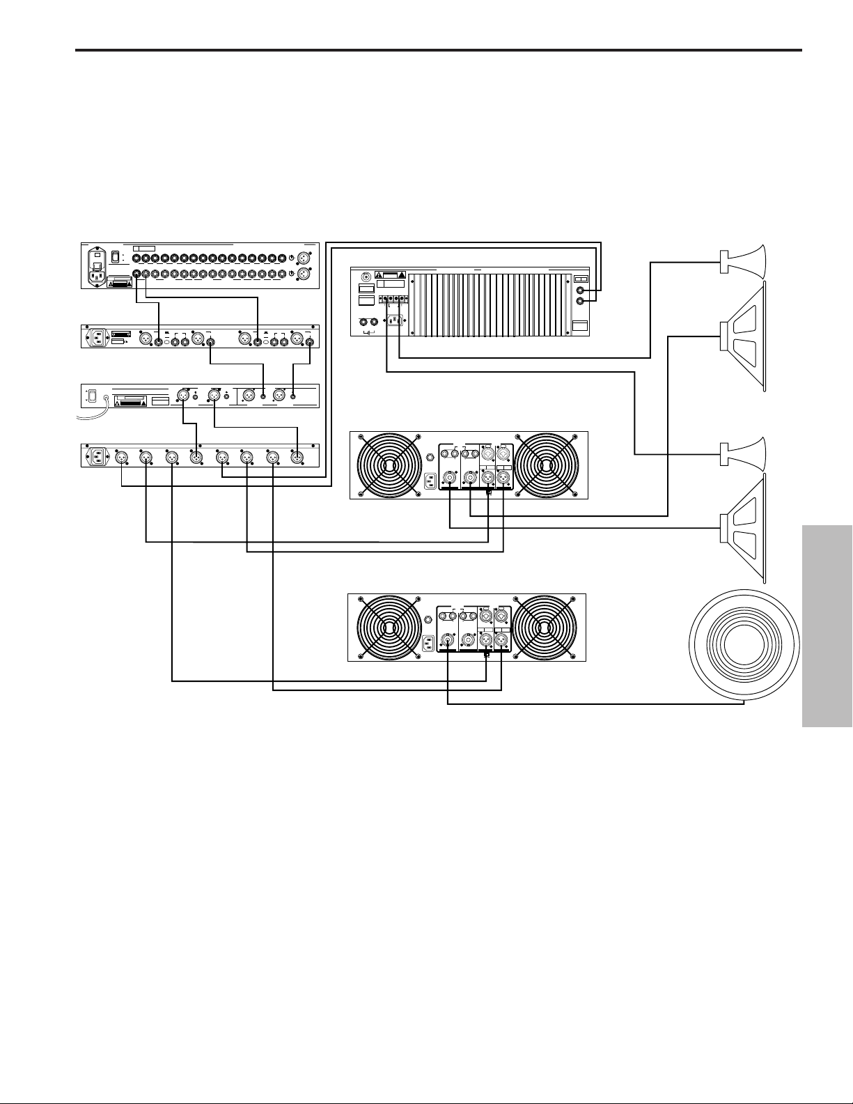
S•com System-Einrichtungen
LIVE BESCHALLUNGS-SYSTEM MIT STEREO-KOMPRESSION
In diesem Beispiel ist der S•com hinter den Mischer und vor den grafischen EQ geschaltet und
komprimiert dadurch das breitbandige Signal des Mischers.
43
DEUTSCHE
PL1602 Mixer
PL 1602
16 CHANNEL LINE MIXER
S / N
POWER
110
ON
OFF
AVIS:
RISQUE DE CHOC ELECTRIQUE
NE PAS OUVRIR
DO NOT EXPOSE THIS EQUIPMENT
TO RAIN OR MOISTURE
POWER
120V - 60 Hz 35W
RATING
CAUTION
RISK OF ELECTRIC SHOCK
~115V(0.3A)
230V(0.15A)
50/60Hz 30W
S•Com
SERIAL NUMBER
MADE IN CHINA
_ mA SLOW BLOW FUSE FOR 115V
_ mA SLOW BLOW FUSE FOR 220V
E30 Dual 15 Band EQ
E30 2/3 OCTAVE STEREO 15 BAND GRAPHIC EQUALIZER
AVIS: RISQUE DE CHOC ELECTRIQUE NE PAS OUVRIR. DO NOT EXPOSE
THIS EQUIPMENT TO RAIN OR MOISTURE.
ON
~AC INPUT
OFF
POWER
115V/230V 50/60Hz13W
BUS
INSERTS
BALANCED 600 +4db
!
MIXER LINKING
DO NOT OPEN
TIP + RING - SLEEVE GND
+4
BALANCED
CAUTION
INPUT
RISK OF ELECTRIC SHOCK
DO NOT OPEN.
POWER
RATING
120V - 60 Hz 20W
CAUTION
RISK OF ELECTRIC SHOCK
DO NOT OPEN
-10
INPUT OUTPUT
2
1
LEVEL
3
BALANCED <100Ω
0db UNITY GAIN
SERIAL NUMBER
!
S•3 Way
CH 2
HIGH
OUTPUT
2
2
2
1
1
CH 2
CH 2
MID
HIGH
3
3
3
OUTPUT
OUTPUT
MONO
MONO
HIGH-MID
HIGH
OUTPUT
OUTPUT
INPUTS BALANCED 10K‰ -30 to +4db TIP + RING - SLEEVE GND.
AUX
RETURNS
UNBALANCED 10K‰
CHANNEL 2
KEY
2
3
OUTPUTS
BALANCED
<100KΩ 0db
UNITY GAIN
CH 2
LOW
OUTPUT
2
1
1
CH 2
LOW
3
OUTPUT
2R
1L2R3L4RLRLR
1L
AUX SEND
UNBALANCED
2K‰ +4db
XLR
PIN 1 GND
BALANCED
PIN 2 HOT
OUTPUT
PIN 3 NEG
1
S com Plus
PHONE
TIP - POS
RING - NEG
SLEEVE - GND
BALANCED <100Ω
0db UNITY GAIN
CH 2
INPUT
2
1
CH 2
INPUT
3
SAMSON TECHNOLOGIES CORP., NEW YORK, U.S.A.
1L2R3L4R5L6R7L8R9L10R11L12R13L14R15L16R
6R 5L 4R 3L 2R 1L
INSERTS TIP RETURN RING SEND
CHANNEL 1
+4
KEY
BALANCED
INPUT
INPUT
-10
OUTPUT
2
1
LEVEL
3
INPUTS
BALANCED
0db UNITY GAIN
BALANCED
BALANCED
10KΩ
<100KΩ 0db
UNITY GAIN
CH 1
HIGH
OUTPUT
CH 1
HIGH
OUTPUT
CHANNEL ACHANNEL BCHANNEL ACHANNEL B
CH 1
LOW
OUTPUT
2
2
1
1
CH 1
CH 1
LOW
MID
3
3
OUTPUT
OUTPUT
MONO
MONO
LOW
LOW-MID
OUTPUT
OUTPUT
MIC 1
-10
2
3
0
1
-40+4
TRIM
-10
2
3
0
1
-40+4
TRIM
MIC 3MAIN OUT
BALANCED
OUTPUT
2
1
3
BALANCED
0db UNITY GAIN
BALANCED
10KΩ
SAMSON
TECHNOLOGIES
CORP.,
NEW YORK, U.S.A.
Servo 550 Power Amp (High)
CAUTION
RISK OF ELECTRIC SHOCK
DO NOT OPEN
F
E
U
S
SERIAL
FUSE
NUMBER
FUSE RATING
12A/250V (115V)
6A/250V (230V)
USE CLASS 2 WIRING MAXIMUM LOAD IMPEDANCE 4Ω
CAUTION
HEATSINK MAY BE
HOT! DO NOT BLOCK
AIRFLOW OR OVER-
HEATING MAY OCCUR
TO PREVENT SHOCK DO
GROUND
+RIGHT
NOT OPEN. NO USER
SERVICABLE PARTS
INSIDE. REFER SERVICING
TO QUALIFIED SERVICE
OUTPUT 250W/4Ω
PERSONNEL. TO PREVENT
FIRE OR SHOCK HAZARD
DO NOT EXPOSE TO RAIN
OR MOISTURE.
RIGHT
~AC INPUT
LEFT
115V/230W, 50/60HZ
510W (115V)900W (230V)
SERVO 550 STUDIO AMPLIFIER
!
LEFT+
SAMSON TECHNOLOGIES CORP., HICKSVILLE, NEW YORK
BRIDGED
TIP RING SLEEVE
SLEEVE GND
MONO STEREO
LEFT
RIGHT
INPUTS
(BALANCED
10KΩ/0dBm0)
TIP +
RING -
S1500 Power Amp (Mid)
INPUT
MODE
CHANNEL
STEREO
1 INPUT
2 WAY
2
1
CHANNEL
STEREO
1 INPUT
3 WAY
3
MONO
MONO
INPUT
4 WAY
PUSH TO RESET
115V 60Hz, 920W
OUTPUT
20A/250V
(4Ω~8Ω) (4Ω~8Ω)
~AC INPUT
(4Ω~8Ω) (4Ω~8Ω)
CH 2 CH 1
BALANCED
0dBm
TIP=HOT
TRS
RING=COLD
BALANCED
SLEEVE=GND
CH 2 CH 1
BRIDGED PARALLEL
STEREO
BALANCED
0dBm
3=COLD
XLR
2=HOT
BALANCED
1=GND
Left High / Mid
Right High / Mid
S2000 Power Amp
(Bridged Mono Low)
INPUT
OUTPUT
PUSH TO RESET
25A/250V
115V 60Hz, 1100W
(4Ω~8Ω) (4Ω~8Ω)
~AC INPUT
(4Ω~8Ω) (4Ω~8Ω)
CH 2 CH 1
BALANCED
0dBm
TRS
BALANCED
CH 2 CH 1
BRIDGED PARALLEL
STEREO
BALANCED
0dBm
TIP=HOT
3=COLD
XLR
RING=COLD
2=HOT
BALANCED
SLEEVE=GND
1=GND
Mono
Sub
Page 45
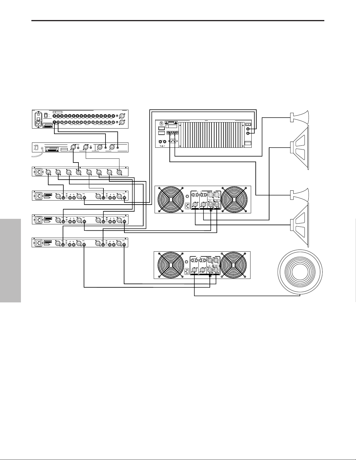
S•com System-Einrichtungen
LIVE BESCHALLUNGS-SYSTEM MIT MULTIBAND-KOMPRESSION
In diesem Beispiel werden drei S•com hinter Mischer, EQ und Crossover geschaltet und
ermöglichen so eine individuelle Kompression der Bässe, Mitten und Höhen.
44
DEUTSCHE
PL1602 Mixer
PL 1602
16 CHANNEL LINE MIXER
S / N
POWER
110
ON
OFF
AVIS:
RISQUE DE CHOC ELECTRIQUE
NE PAS OUVRIR
DO NOT EXPOSE THIS EQUIPMENT
TO RAIN OR MOISTURE
POWER
120V - 60 Hz 35W
RATING
RISK OF ELECTRIC SHOCK
~115V(0.3A)
230V(0.15A)
50/60Hz 30W
E30 Dual 15 Band EQ
E30 2/3 OCTAVE STEREO 15 BAND GRAPHIC EQUALIZER
AVIS: RISQUE DE CHOC ELECTRIQUE NE PAS OUVRIR. DO NOT EXPOSE
THIS EQUIPMENT TO RAIN OR MOISTURE.
ON
~AC INPUT
OFF
POWER
115V/230V 50/60Hz13W
S•3 Way
S•Com
SERIAL NUMBER
MADE IN CHINA
_ mA SLOW BLOW FUSE FOR 115V
_ mA SLOW BLOW FUSE FOR 220V
S•Com
SERIAL NUMBER
MADE IN CHINA
_ mA SLOW BLOW FUSE FOR 115V
_ mA SLOW BLOW FUSE FOR 220V
BUS
CAUTION
INSERTS
BALANCED 600 +4db
!
MIXER LINKING
DO NOT OPEN
TIP + RING - SLEEVE GND
BALANCED <100Ω
POWER
120V - 60 Hz 20W
RATING
CAUTION
RISK OF ELECTRIC SHOCK
DO NOT OPEN
2
1
3
CAUTION
RISK OF ELECTRIC SHOCK
DO NOT OPEN.
CAUTION
RISK OF ELECTRIC SHOCK
DO NOT OPEN.
0db UNITY GAIN
SERIAL NUMBER
!
CH 2
HIGH
OUTPUT
2
2
1
1
CH 2
CH 2
MID
HIGH
3
3
OUTPUT
OUTPUT
MONO
MONO
HIGH-MID
HIGH
OUTPUT
OUTPUT
CHANNEL 2
+4
BALANCED
INPUT
-10
INPUT OUTPUT
2
1
LEVEL
3
CHANNEL 2
+4
BALANCED
INPUT
-10
INPUT OUTPUT
2
1
LEVEL
3
S•Com
CHANNEL 2
+4
BALANCED
CAUTION
INPUT
RISK OF ELECTRIC SHOCK
DO NOT OPEN.
SERIAL NUMBER
MADE IN CHINA
_ mA SLOW BLOW FUSE FOR 115V
_ mA SLOW BLOW FUSE FOR 220V
-10
INPUT OUTPUT
2
1
LEVEL
3
INPUTS BALANCED 10KΩ -30 to +4db TIP + RING - SLEEVE GND.
1L2R3L4RLRLR
AUX
RETURNS
UNBALANCED 10KΩ
OUTPUTS
BALANCED
<100KΩ 0db
UNITY GAIN
CH 2
CH 2
INPUT
LOW
OUTPUT
2
1
CH 2
CH 2
LOW
INPUT
3
OUTPUT
KEY
BALANCED
2
1
3
KEY
BALANCED
2
1
3
KEY
BALANCED
OUTPUT
2
1
3
SAMSON TECHNOLOGIES CORP., NEW YORK, U.S.A.
2R
6R 5L 4R 3L 2R 1L
1L
AUX SEND
UNBALANCED
2KΩ +4db
BALANCED <100Ω
0db UNITY GAIN
BALANCED
<100KΩ 0db
UNITY GAIN
CH 1
HIGH
OUTPUT
2
1
CH 1
HIGH
3
OUTPUT
XLR
PIN 1 GND
PIN 2 HOT
OUTPUT
PIN 3 NEG
S com
PHONE
TIP - POS
RING - NEG
SLEEVE - GND
XLR
PIN 1 GND
PIN 2 HOT
OUTPUT
PIN 3 NEG
S com
PHONE
TIP - POS
RING - NEG
SLEEVE - GND
XLR
PIN 1 GND
PIN 2 HOT
PIN 3 NEG
S com
PHONE
TIP - POS
RING - NEG
SLEEVE - GND
INSERTS TIP RETURN RING SEND
2
1
3
BALANCED
2
1
3
BALANCED
2
1
3
BALANCED
2
1
3
MIC 1
-10
2
3
0
1
-40+4
TRIM
1L2R3L4R5L6R7L8R9L10R11L12R13L14R15L16R
-10
2
3
0
1
-40+4
TRIM
MIC 3MAIN OUT
INPUTS
BALANCED
BALANCED
0db UNITY GAIN
0db UNITY GAIN
BALANCED
BALANCED
10KΩ
10KΩ
SAMSON
TECHNOLOGIES
CORP.,
NEW YORK, U.S.A.
CHANNEL ACHANNEL BCHANNEL ACHANNEL B
MODE
CHANNEL
CH 1
STEREO
1 INPUT
LOW
2 WAY
OUTPUT
2
2
1
1
CH 1
CH 1
MID
OUTPUT
MONO
LOW-MID
OUTPUT
CHANNEL
STEREO
LOW
1 INPUT
3 WAY
3
3
OUTPUT
MONO
MONO
MONO
LOW
INPUT
4 WAY
OUTPUT
Servo 550 Power Amp (High)
CAUTION
RISK OF ELECTRIC SHOCK
DO NOT OPEN
F
E
U
S
SERIAL
FUSE
NUMBER
FUSE RATING
12A/250V (115V)
6A/250V (230V)
USE CLASS 2 WIRING MAXIMUM LOAD IMPEDANCE 4Ω
CAUTION
HEATSINK MAY BE
HOT! DO NOT BLOCK
AIRFLOW OR OVERHEATING MAY OCCUR
TO PREVENT SHOCK DO
GROUND
+RIGHT
NOT OPEN. NO USER
SERVICABLE PARTS
INSIDE. REFER SERVICING
TO QUALIFIED SERVICE
OUTPUT 250W/4Ω
PERSONNEL. TO PREVENT
FIRE OR SHOCK HAZARD
DO NOT EXPOSE TO RAIN
OR MOISTURE.
RIGHT
~AC INPUT
LEFT
115V/230W, 50/60HZ
510W (115V)900W (230V)
SERVO 550 STUDIO AMPLIFIER
!
LEFT+
SAMSON TECHNOLOGIES CORP., HICKSVILLE, NEW YORK
BRIDGED
TIP RING SLEEVE
MONO STEREO
LEFT
RIGHT
INPUTS
(BALANCED
10KΩ/0dBm0)
TIP +
RING SLEEVE GND
S1500 Power Amp (Mid)
INPUT
CHANNEL 1
+4
KEY
INPUT
INPUT
INPUT
LEVEL
BALANCED
OUTPUT
INPUT
-10
OUTPUT
2
1
LEVEL
3
CHANNEL 1
+4
KEY
BALANCED
OUTPUT
INPUT
-10
OUTPUT
2
1
LEVEL
3
CHANNEL 1
+4
KEY
BALANCED
OUTPUT
INPUT
-10
OUTPUT
2
1
3
S2000 Power Amp
PUSH TO RESET
~AC INPUT
115V 60Hz, 920W
OUTPUT
20A/250V
(4Ω~8Ω) (4Ω~8Ω)
(4Ω~8Ω) (4Ω~8Ω)
CH 2 CH 1
BALANCED
0dBm
TRS
BALANCED
CH 2 CH 1
BRIDGED PARALLEL
STEREO
BALANCED
0dBm
TIP=HOT
3=COLD
XLR
RING=COLD
2=HOT
BALANCED
SLEEVE=GND
1=GND
Left High / Mid
Right High / Mid
(Bridged Mono Low)
INPUT
OUTPUT
PUSH TO RESET
25A/250V
115V 60Hz, 1100W
(4Ω~8Ω) (4Ω~8Ω)
~AC INPUT
(4Ω~8Ω) (4Ω~8Ω)
CH 2 CH 1
BALANCED
0dBm
TIP=HOT
TRS
RING=COLD
BALANCED
SLEEVE=GND
CH 2 CH 1
BRIDGED PARALLEL
STEREO
BALANCED
0dBm
3=COLD
XLR
2=HOT
BALANCED
1=GND
Mono
Sub
Page 46
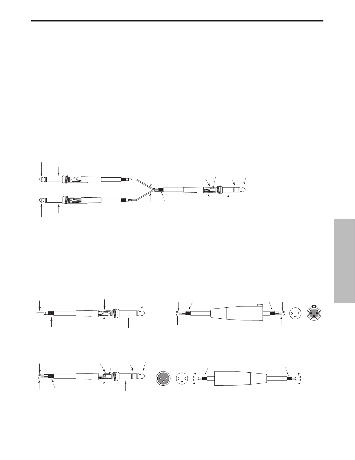
S•com Anschlüsse
Asymmetrischer 1/4” Anschluss
Insert-Kabel 1/4”TRS-Stecker auf zwei 1/4” TS-Stecker
in Send und Return-Konfiguration.
XLR Symmetrisch / Verdrahtungsanleitung
S•com ANSCHLIESSEN
Es gibt verschiedene Möglichkeiten, um den S•com zwischenzuschalten und für ein breites Spektrum an Anwendungen
zu nutzen. Der S•com verfügt über servo-symmetrierte Eingänge und Ausgänge, wodurch sich symmetrische und asym-
metrische Signale ohne Signalverlust anschließen lassen. Sie können den S•com für ein Einzelinstrument verwenden,
indem Sie ihn mit dem Einschleifweg des betreffenden Kanals verbinden, oder für eine gesamte Mischung, indem Sie
ihn "in-line" zwischen die Ausgänge eines Mischer und die Eingänge einer Endstufe oder eines EQs schalten.
EINSCHLEIFPUNKTE
Viele Mischer bieten heutzutage Kanal- und Bus- oder Gruppen-Inserts. Insert-Punkte sind Einschleif-Eingänge
und -Ausgänge, die das Kanal- oder Bus-Signal unterbrechen, damit externe Prozessoren angeschlossen werden können. Kanal-Einschleifpunkte sind dann ideal, wenn man mit dem S•com einen einzelnen Kanal – z. B.
für Gesang, Bass oder Gitarre – bearbeiten möchte. Bus-Einschleifpunkte sind ideal zum Komprimieren von
Instrumentengruppen wie Gesangsstimmen, Streicher oder Drums geeignet. Der Anschluss eines KanalEinschleifwegs besteht möglicherweise aus nur einer TRS-Klinkenbuchse für Send & Return. Benutzen Sie in
diesem Fall ein Insert "Y" Kabel, das wie in dem Verdrahtungsplan unten konfiguriert ist.
IN-LINE
Bei der Live-Beschallung können Sie den S•com in-line zwischen einem Mischer und EQ oder einer Endstufe
installieren. Für diese Anwendungen bietet der S•com sowohl 1/4" Klinken- als auch XLR-Anschlüsse, die sich
problemlos mit fast jedem professionellen Audiogerät verbinden lassen. Gehen Sie bei Ihrer speziellen
Installation nach den folgenden Verdrahtungsplänen vor.
Symmetrischer 1/4“ Klinkenstecker
45
DEUTSCHE
Spitze (Send)
Schirm (Masse)
Send (Spitze)
Return (Ring)
Send (Spitze)
Ring (Return)
Spitze (Send)
Return (Ring)
Schirm (Masse)
Spitze (Return)
Masse
Masse
Schirm (Masse)
Signal
Masse
Masse
Schirm (Masse)
Spitze (Signal)Signal
Heiss
Kalt
Masse(1)Masse
XLR-Buchse
Heiss (2)
Kalt (3)
1
2
3
Lötpunkte Endansicht
Signal (Spitze)
Signal (Ring)
Signal (Spitze)
Ring (signal)
Pointe (Spitze)
Heiss (2)
Masse (1) Masse
Heiss
21
3
Signal (Ring)
Masse
Masse
Schirm (Masse)
12
Endansicht Lötpunkte
2
3
3
1
Kalt(3)
XLR-Stecker
Kalt
Page 47

Prólogo de Ray Kennedy
La utilización de compresores y limitadores en la grabación y la mezcla es una de las posibilidades más
importantes de que se dispone, y es mucho más útil que lo que muchos creen. Para mi, la compresión
es mucho más importante para un sonido que no un equipo de control de la dinámica. Cada modelo
tiene su propio sonido y aplicación ideal, razón por la cual yo dispongo de unas 40 unidades entre las
que escoger. Aprender el tipo de unidad y los ajustes que deben utilizarse precisa de muchas pruebas
y experimentos, pero con el tiempo encontrará las mejores aplicaciones.
La limitación de picos y la compresión ligera son adecuadas básicamente para maximizar los niveles en
cinta o disco sin incorporar mucha coloración. Esencialmente rebajando los picos y subiendo el volumen
de los fragmentos más sosegados de un sonido para reducir así la gama dinámica. Un tiempo de ataque
lento y un tiempo de desvanecimiento rápido crean un sonido más transparente. A mi personalmente
me gusta el sonido de la compresión, y algunas veces lo utilizo de manera extrema. Según el tipo de
unidad y los ajustes, pueden conseguirse muchos caracteres tonales, como un sonido espeso, con
ambiente, duro, suave, ecualizado, y muchos más. Mi truco favorito de “compresión obsesiva”' es hacer
que la parte vocal quede suspendida en la mezcla, directa e íntima, como si el cantante estuviera ahí
delante mismo pero sin cantar muy alto. Mi colega Steve Earle dice que la cantidad de compresión que
utilizamos en las partes vocales de sus discos permite a la gente saber qué ha tomado para desayunar.
En muchos aspectos, se convierte en un sustituto para la reverberación y, si se utiliza en modo extremo,
capta todo el ambiente alrededor de un micrófono para partes vocales y también extrae el carácter de
lo más profundo de sus cuerdas vocales. Con un micrófono aéreo o de ambiente es posible cambiar el
tamaño percibido de la habitación haciendo que absorba el sonido que va cayendo mientras éste se
aleja. Aquí también, un tiempo de ataque lento y un tiempo de desvanecimiento rápido darán los
mejores resultados, ya que permiten controlar el nivel umbral de manera más estricta.
La limitación y la compresión del bus en estéreo es también un método muy adecuado para combinar
pistas y hacer que una banda suene más conjuntada de lo que realmente está. También permite una
mayor saturación en las mezclas analógicas de dos pistas y una modulación más completa en los
formatos digitales. Para mi, no es nada extraño utilizar tres limitadores estéreo antes de pasar al disco
duro al crear un master, desde el cual se cortarán las partes finales.
Normalmente, al hacer pasar una señal a través de diversos compresores es posible conseguir unos
resultados interesantes que no pueden lograrse con una única unidad. No hay ninguna norma, pero es
importante saber que existen muchos diseños diferentes para procesar el sonido. Algunos son
totalmente de tubo, algunos de tubo y ópticos, sólo ópticos, transistores FET, VCA's (amplificadores de
control de la tensión), Clase A puros, Clase A/B, Digitales, así como otras combinaciones.
Ahora, por fin, hemos llegado a una época de VCAs de gran calidad que no son muy caros y que
permiten unos diseños muy sofisticados y versátiles, como es el caso de las unidades S-Class de
Samson.
Ray Kennedy
Ray Kennedy es un productor, ingeniero y compositor
establecido en Nashville cuya compañía productora, Twang
Trust, una sociedad entre Ray y el cantante y compositor Steve
Earle, puede presentar grabaciones e interpretaciones de
artistas muy famosos, como Steve Earle, Art Garfunkel, Willie
and Waylon, Farm Aid, The Del McCoury Band, Nancy Griffith,
Lucinda Williams, David Alan Coe, Shaver, V-Roys y Rosie
Flores.
46
ESPAÑOL
Page 48
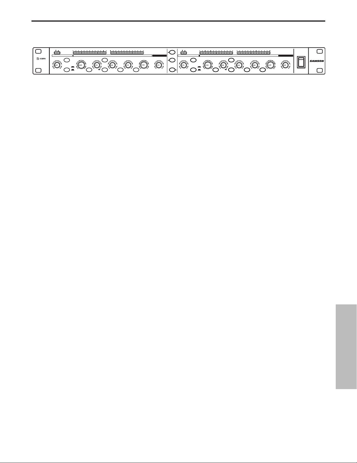
Características y funciones del S•com
El procesador de dinámica Samson S com utiliza la última tecnología en el diseño de gestión de la ganancia. A
continuación encontrará algunas de sus principales características y funciones:
• Procesador de dinámica de dos canales y con todas las funciones necesarias con secciones
Compressor/Limiter, Expander/Gate, De-Esser y Limiter.
• El SKD (Detector de Codo Inteligente) cambia de un codo suave a uno fuerte según el nivel de la señal
de entrada.
• El modo AEG (Generador de Envolvente Automático) ajusta de manera constante los tiempos de
ataque y de desvanecimiento del compresor según la señal de entrada. También es posible el ajuste
manual de los tiempos de ataque y de desvanecimiento.
• Medidor de entrada/salida de LEDs de 12 segmentos, y medidor de reducción de la ganancia de LEDs
de 12 segmentos.
• Control externo con el conmutador Key Listen disponible en el panel frontal.
• Enhancer ajustable para restablecer la pérdida de las frecuencias más altas resultante de una fuerte
reducción de la ganancia.
• Expander/Gate con control de umbral de disparo variable y tiempo de desvanecimiento rápido y lento
seleccionable.
• La función Gate puede estar desde desactivada hasta actuar como expansor a niveles más bajos.
• LEDs de compuerta abierta y cerrada.
• Limitador de picos con control de umbral independiente y LED de picos.
• Circuito Spectra que permite perfilar las frecuencias medias-altas para eliminar la sibilancia.
• Diseño de circuitos avanzados que utiliza amplificadores de bajo nivel de ruido y VCAs de alta calidad.
• Conmutador Stereo Link.
• Entradas y salidas servoequilibradas en los conectores XLR y de 1/4”.
• Niveles operativos de +4 y –10 seleccionables.
• Selectores de alta calidad con 41 posiciones y conmutadores con iluminación posterior.
• El elegante panel frontal pulido de color azul eléctrico anodizado es tan sencillo de leer como agradable
de mirar.
• Garantía ampliada a tres años.
47
ESPAÑOL
STEREO
COMPRESSOR
GAIN REDUCTION dB INPUT / OUTPUT LEVEL dB
30 24 2127 18 15 9 612 4 2 1 -30 -18 -12-24 -6 -3 +3 +60 +9 +12+18
THRESHOLDTRIGGER RATIO ATTACK RELEASE OUTPUT ENHANCER
-10
10
GATE KEY
-30
FAST
+20-40
SLOW
dB
RELEASE SPECTRA KEY AUTO I/O METER
OFF +10
20
050
dB
COMPRESSOR / LIMITEREXPANDER/GATE
4:1
50
LISTEN
62
+10
.3 300
1
dB
mSec
OFF 10
STEREO LINK
IN/OUT 1
IN/OUT 2
20
GATE
GATE KEY
050
OFF +10
dB
RELEASE
5
73
0
1
20015
3.15
-10
.05 5
Sec
+10
+20-20
dB
GAIN REDUCTION dB INPUT / OUTPUT LEVEL dB
30 24 2127 18 15 9 612 4 2 1 -30 -18 -12-24 -6 -3 +3 +60 +9 +12+18
THRESHOLDTRIGGER RATIO ATTACK RELEASE OUTPUT ENHANCER
-10
10
-30
FAST
+20-40
SLOW
dB
COMPRESSOR / LIMITEREXPANDER/GATE
4:1
50
LISTEN
62
+10
SPECTRA KEY AUTO I/O METER
.3 300
1
dB
1
20015
3.15
.05 5
mSec
Sec
Sec
0
-10
+10
+20-20
dB
CH 2
CH 2CH 1
OFF 10
POWER
5
73
Page 49
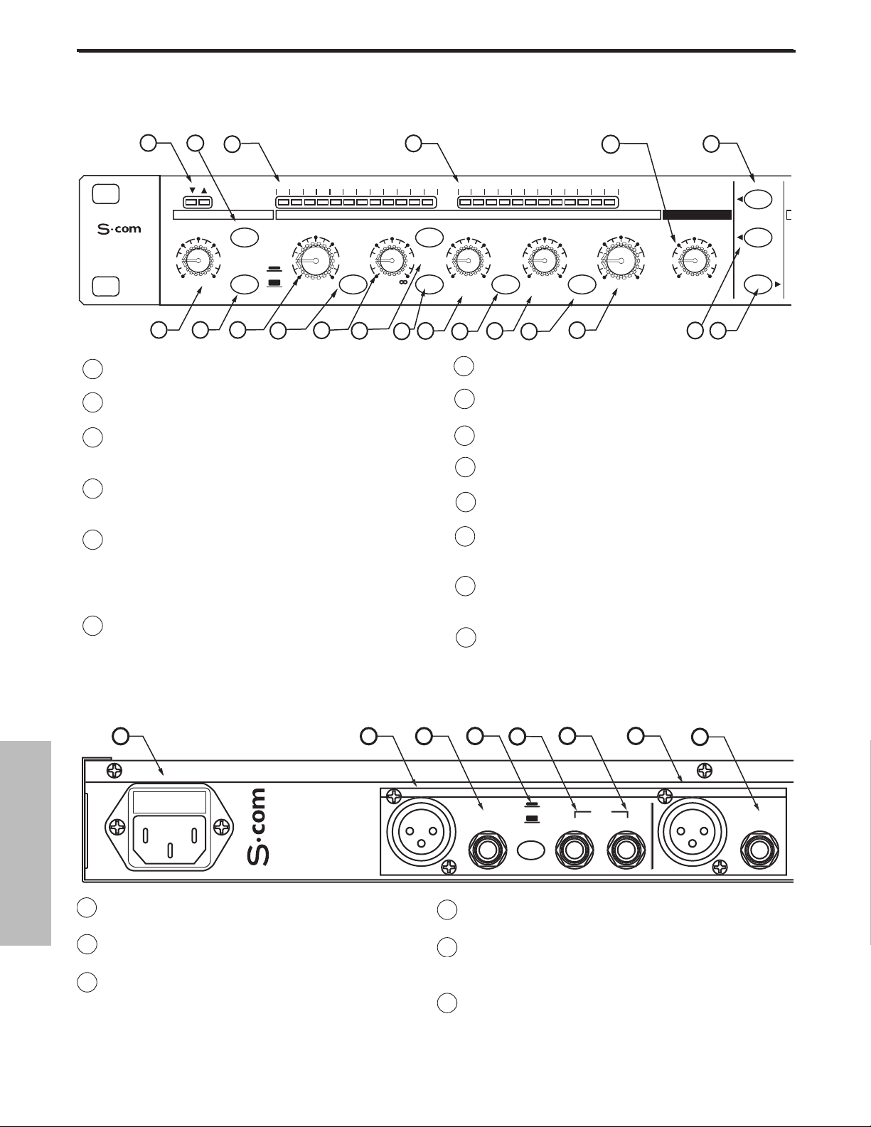
A ENTRADA DE CA - Conector para el cable de
alimentación de CA estándar IEC.
B ENTRADA XLR DEL CANAL 2 - Entrada de línea
XLR equilibrada.
C ENTRADA TRS DE 1/4”DEL CANAL 2 - Entrada
de línea TRS de 1/4” equilibrada.
D CONMUTADOR DE NIVEL OPERATIVO - Cambia
el nivel operativo de -10dB a +4dB.
E KEY INPUT DEL CANAL 2 - Conexión de entrada
que permite el control externo del circuito de
detección del compresor del S•com.
F KEY OUTPUT DEL CANAL 2 - El circuito del
detector del S• com se envía aquí. Utilice Key
Output para procesar el detector del compresor
con un efecto externo, como un ecualizador.
1
LEDS DE COMPUERTA ABIERTA Y CERRADA - Indican si
la compuerta está abierta o cerrada.
2 CONMUTADOR GATE - Selecciona el modo Gate o
Expander.
3
MEDIDOR GAIN REDUCTION - Muestra la cantidad de
reducción de la ganancia al activar el circuito de la
sección Compressor.
4
MEDIDOR INPUT/OUTPUT - Muestra el nivel de la señal
de entrada o salida según la posición del conmutador
I/O meter.
5 NIVEL DEL ENHANCER - Se utiliza para ajustar el
nivel del circuito de Recuperación del Espectro
Mejorada del S• com, y restable la pérdida de
frecuencias altas resultante de una reducción de la
ganancia extrema.
6 CONMUTADOR STEREO LINK - Si está activado,las
funciones del canal 2 se controlan con los ajustes del
canal 1.
0
7 CONTROLES DEL CANAL 2 - Los mismos mandos y
conmutadores que en el canal 1 .
8 CONMUTADOR POWER - Cuando está activado, el
S•com está en marcha.
9 OREJAS PARA RACK - Se utilizan para el montaje
en un rack estándar de 19 pulgadas.
10 TRIGGER- Controla el nivel umbral al que se activa
la sección Expander/Gate.
11 CONMUTADOR RELEASE -
Selecciona un tiempo de
desvanecimiento rápido o lento para EXPANDER/GATE.
12 THRESHOLD - Se utiliza para ajustar el nivel de
señal mínimo al que empezará a funcionar el
circuito de la sección Compressor.
13 CONMUTADOR SPECTRA - Activa el circuito
SPECTRA del S•com para perfilar las frecuencias
altas.
14 RATIO - Controla la cantidad de reducción de la
ganancia de manera proporcional a la cantidad de
señal por encima del nivel umbral.
D
OUTPUT
D
UT
UT
OUTPUT
CHANNEL 2
0
48
ESPAÑOL
Controles y funciones
DISTRIBUCIÓN DEL PANEL POSTERIOR
DISTRIBUCIÓN DEL PANEL FRONTAL
10
2
20
OFF +10
dB
11
3
30 24 2127 18 15 9 612 4 2 1 -30 -18 -12-24 -6 -3 +3 +60 +9 +12 +18
GATE KEY
050
FAST
SLOW
RELEASE SPECTRA KEY AUTO I/O METER
12
13
GAIN REDUCTION dB INPUT / OUTPUT LEVEL dB
THRESHOLDTRIGGER RATIO ATTACK RELEASE OUTPUT ENHANCER
10
-10
-30
+10
+20-40
dB
14
15
4:1
1
dB
16
1
STEREO
COMPRESSOR
4
COMPRESSOR / LIMITEREXPANDER/GATE
62
5
CH 1
0
-10
+10
+20-20
dB
5
OFF 10
22
LISTEN
17
50
.3 300
mSec
18
20015
19
.05 5
20
1
3.15
Sec
21
6
73
23
STEREO LINK
IN/OUT 1
IN/OUT 2
5
A
-1
F G
INP
H
BALANCE
B
C
D
BALANCE
INP
E
Page 50
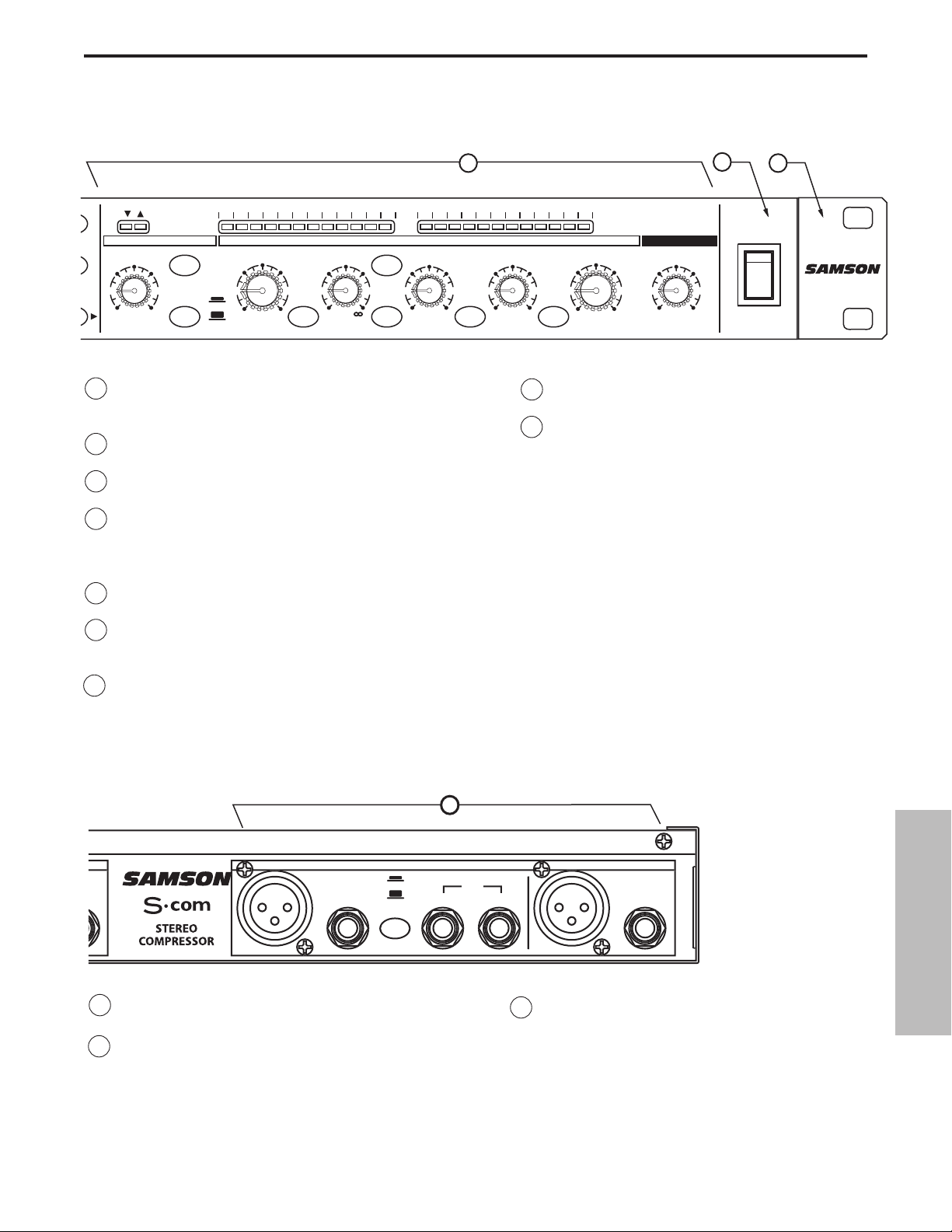
G SALIDA XLR DEL CANAL 2 - Salida de línea XLR
equilibrada.
H SALIDA TRS DE 1/4”DEL CANAL 2 - Salida de
línea TRS de 1/4” equilibrada.
I CHANNEL 1 - Las mismas entradas y salidas
que en el canal 1.
15 CONMUTADOR KEY LISTEN - Cuando está activado, la
señal presente en KEY INPUT se envía directamente a la
salida de canal.
16 CONMUTADOR KEY - Selecciona la entrada de botón
para poder disparar el compresor con una señal externa.
17 ATTACK - Ajusta la cantidad de tiempo que tarda el
compresor en llegar a la reducción de ganancia total.
18 AUTO - Activa el AEG (Generador de Envolvente
Automático) del S •com, que ajusta de manera
automática los tiempos de ataque y de desvanecimiento
según el conenido de la señal.
19 RELEASE - Ajustsa el tiempo que tardará el compresor
en volver a definir el nivel original de la señal.
20 CONMUTADOR DE SELECCIÓN I/O METER - Selecciona
el nivel de entrada o de salida para visualizarlo en el
medidor Input/Output.
21 LEVEL - Controla la cantidad de nivel de salida.
22 CONMUTADOR IN/OUT DEL CANAL 1 -
Activa el canal 1 del S•com.
23 CONMUTADOR IN/OUT DEL CANAL 2 -
Activa el canal 2 del S•com.
D
D
OUTPUT
D
UT
UT
OUTPUT
C
1
0
49
ESPAÑOL
Controles y funciones
GAIN REDUCTION dB INPUT / OUTPUT LEVEL dB
THRESHOLDTRIGGER RATIO ATTACK RELEASE OUTPUT ENHANCER
10
-10
-30
+10
+20-40
dB
SPECTRA KEY AUTO I/O METER
COMPRESSOR / LIMITEREXPANDER/GATE
4:1
LISTEN
62
1
dB
50
.3 300
mSec
20015
LINK
1
2
20
OFF +10
dB
30 24 2127 18 15 9 612 4 2 1 -30 -18 -12-24 -6 -3 +3 +60 +9 +12 +18
GATE
GATE KEY
050
RELEASE
FAST
SLOW
7
CH 2
CH 2
1
.05 5
Sec
Sec
3.15
0
-10
+10
+20-20
dB
OFF 10
8
5
73
POWER
POWER
9
I
HANNEL
E
BALANCE
INP
-1
INP
BALANCE
Page 51
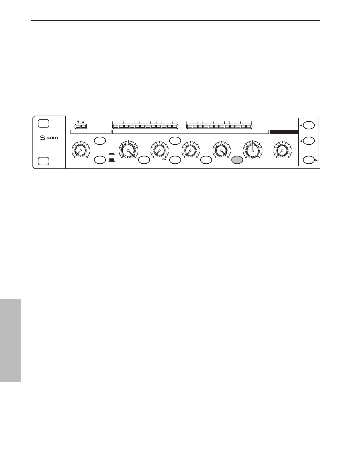
Utilizar el S•com
Tanto si es un ingeniero de audio muy experimentado como si simplemente está empezando, o sólo desea
experimentar, siga los pasos que se indican a continuación para empezar. Las demás secciones de este manual
explican la dinámica básica y los parámetros asociados, las configuraciones del sistema y las aplicaciones para
utilizar el procesamiento de la dinámica para la grabación y para las aplicaciones de sonido en directo.
SETTING UP THE S•com
• Conecte uno o ambos grupos de entradas y salidas a los conectores designados del panel posterior.
• Coloque los controles en las siguientes posiciones:
Con esta configuración, el S•com simplemente dejar pasar la señal de audio aplicando la ganancia definida,
pero sin ningún procesamiento de la dinámica. En este momento es aconsejable comprobar la estructura de
ganancia. Utilice el medidor Input/Output para hacer coincidir el nivel.
• Envíe una señal a una o ambas entradas y salidas del S•com.
• Pulse el conmutador METER para ver si coinciden los niveles de entrada y salida.
COMPRIMIR UNA SEÑAL
La sección del compresor del S•com puede utilizarse para diversas tareas de gestión de la ganancia, incluyendo
grabar señales en un grabador multipistas, como efecto para la mezcla final, crear un master, y aumentar la
intensidad sonora de un sistema de amplificadores de potencia en directo. Para empezar a comprimir la señal,
siga los pasos que se indican a continuación:
• Siga los pasos de la sección anterior, “PREPARAR EL S•com” para normalizar los controles.
• Pulse el conmutador IN de canal (que se encuentra en el centro de la unidad).
• Pulse el conmutador AUTO (se encuentra entre ATTACK y RELEASE).
• Ajuste RATIO a 2:1.
EXPANDER/GATE TRIGGER – OFF
CONMUTADOR GATE – No pulsado
FAST RELEASE – No pulsado
COMPRESSOR THRESHOLD – +20dBu (totalmente en sentido horario)
SPECTRA - No pulsado
RATIO – 1:1
CONMUTADOR KEY - No pulsado
AT TAC K – 0.3 (totalmente en sentido antihorario)
CONMUTADOR AUTO - No pulsado
RELEASE -5 (fully clockwise)
CONMUTADOR METER – Pulsado
OUTPUT LEVEL – O dBu
ENHANCER - OFF (totalmente en sentido antihorario)
CONMUTADOR STEREO LINK – No pulsado
CHANNEL 1 ENGAGE – No pulsado
50
ESPAÑOL
30 24 2127 18 15 9 612 4 2 1 -30 -18 -12-24 -6 -3 +3 +60 +9 +12 +18
STEREO
COMPRESSOR
20
OFF +10
dB
GATE KEY
050
FAST
SLOW
RELEASE SPECTRA KEY AUTO I/O METER
GAIN REDUCTION dB INPUT / OUTPUT LEVEL dB
THRESHOLDTRIGGER RATIO ATTACK RELEASE OUTPUT ENHANCER
-10
10
-30
+10
+20-40
dB
COMPRESSOR / LIMITEREXPANDER/GATE
-10
0
+10
+20-20
dB
4:1
LISTEN
62
1
dB
50
.3 300
mSec
1
20015
.05 5
Sec
3.15
CH 1
OFF 10
STEREO LINK
5
IN/OUT 1
73
IN/OUT 2
Page 52
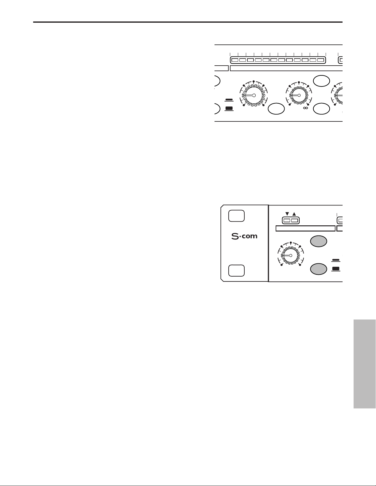
Utilizar el S•com
• Ahora baje gradualmente el nivel de THRESHOLD y
escuche la compresión. Si desea una representación
visual, la cantidad de compresión aparece indicada en
el medidor GAIN REDUCTION.
• Pulse el botón AUTO para experimentar con los
tiempos de ATTACK y RELEASE controlados
manualmente.
OT
S
5
T
APLICAR UNA COMPUERTA A UNA SEÑAL
Los ruidos, zumbidos y siseos no deseados puede eliminarse muy fácilmente utilizando GATE del S•com. La
idea es hacer que la compuerta se abra sólo cuando esté sonando la señal deseada, y enmudecer (compuerta
cerrada) los ruidos, zumbidos y siseos no deseados. Para aplicar una compuerta a la señal, siga los pasos que
se indican a continuación:
• Siga los pasos de la sección anterior, “PREPARAR EL S•com” para normalizar los controles.
• Para activar la sección GATE, compruebe que el conmutador EXPANDER/GATE esté pulsado.
0
3
• Pulse el conmutador RELEASE para seleccionar el
tiempo de desvanecimiento rápido.
• Ahora defina un valor más alto para THRESHOLD y
escuche mientras empieza a aplicarse la compuerta a la
señal. Para una representación visual de la apertura y
cierre de la compuerta, observe los LEDs de compuerta
abierta y cerrada que se encuentran sobre el control
TRIGGER de EXPANDER/GATE.
UTILIZAR EL EXPANSOR A NIVELES MÁS BAJOS
Puede configurar la sección GATE del S•com para que funcione como un EXPANSOR A NIVELES MÁS BAJOS
para bajar el volumen de una señal. Siga los pasos que se indican a continuación:
• Siga los pasos de la sección anterior, “PREPARAR EL S•com” para normalizar los controles.
• Para activar la sección EXPANDER, compruebe que el botón EXPANDER/GATE no esté pulsado.
• Compruebe que el conmutador RELEASE no esté pulsado para seleccionar un tiempo de
desvanecimiento lento.
• Ahora defina un valor más alto para TRIGGER y escuche mientras la señal empieza a oírse más suave.
51
ESPAÑOL
30 24 2127 18 15 9 612 4 2 1 -3
E
E KEY
-30
FAST
SLOW
SE SPECTRA KEY
GAIN REDUCTION dB
THRESHOLD RATIO AT
-10
10
+10
dB
+20-40
1
4:1
dB
COMPRESS
LISTEN
62
15
.3
m
3
STEREO
COMPRESSOR
EXPANDER/GATE
TRIGGER
20
GATE
050
OFF +10
dB
RELEASE
FAST
SLOW
-
Page 53
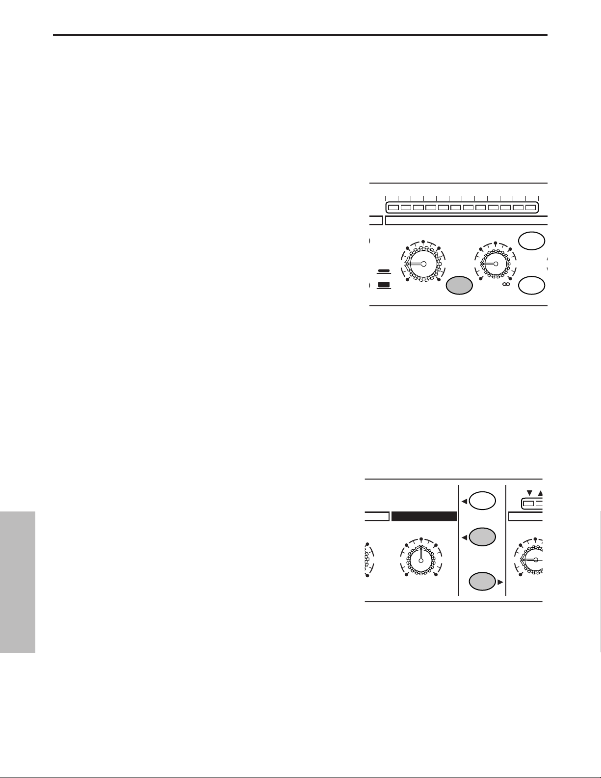
Utilizar el S•com
UTILIZAR EL ENHANCER
Es posible utilizar el conmutador ENHANCER del S•com para activar el circuito EFR (Recuperación de
Frecuencia Mejorada). Al utilizar el ENHANCER, el circuito EFR del S•com restablece el contenido de
frecuencias altas que puede perderse al aplicar una reducción de la ganancia muy alta. El circuito EFR del
S•com lo consigue volviendo a añadir el extremo de frecuencias altas de la señal original en una cantidad igual
a la de reducción de la ganancia.
• Siga los pasos de la sección anterior, “PREPARAR EL
S•com” para normalizar los controles, y haga pasar una
señal, como un CD, a través del S•com.
• Pulse el conmutador IN de canal (que se encuentra en el
centro de la unidad).
• Pulse el conmutador AUTO (que se encuentra entre
ATTACK y RELEASE).
• Ajuste RATIO a 6 - 8:1.
• Suba gradualmente el ENHANCER y escuche como se
restablece el extremo de frecuencias altas.
UTILIZAR EL SPECTRA
La sección SPECTRA del S•com es una herramienta muy potente para eliminar problemas muy molestos como
una sibilancia muy fuerte en las pistas vocales o en unos platos muy brillantes. Para escuchar el efecto de
SPECTRA, pruebe lo siguiente:
• Siga los pasos de la sección anterior, “PREPARAR EL S•com”
para normalizar los controles.
• Pulse el conmutador IN de canal (que se encuentra en el
centro de la unidad).
• Haga pasar una señal con una sibilancia muy fuerte por el
S•com.
• Para activar la sección SPECTRA, compruebe que el
conmutador SPECTRA esté pulsado.
• Ahora escuche cómo el Spectra del S•com reduce la sibilancia.
E
5
A
1
E
52
ESPAÑOL
30 24 2127 18 15 9 612 4 2 1
-30
FAST
SLOW
GAIN REDUCTION dB
THRESHOLD RATIO
-10
10
+10
+20-40
dB
SPECTRA KEY
4:1
1
dB
COMPR
KEY
LISTEN
62
1
+10
CH 1
ENHANCER
5
OFF 10
73
STEREO LINK
IN/OUT 1
IN/OUT 2
50
EXP
TRIGG
20
OFF +
dB
Page 54

Procesamiento de la dinámica 101
Para empezar a comprender el procesamiento de la dinámica, en primer lugar debemos entender qué es la dinámica.
La dinámica, o la gama dinámica de una señal o de un equipo de audio, es la cantidad de nivel entre la salida más
suave y la más alta posibles. El procesamiento de la dinámica se aplica a una señal para gestionar los cambios en el
nivel. Existen varios tipos de unidades de procesamiento disponibles para controlar la dinámica, que incluyen
Compuertas de ruido, Expansores, Compresores, Limitadores y De-Essers. Todos estos procesos tienen un efecto
concreto sobre una señal, pero un elemento común que comparten es que, de una u otra manera, controlan la
ganancia. Algunos procesadores de dinámica controlan la ganancia de una manera muy sutil reduciendo ligeramente
la intensidad sonora de una señal, mientras que otros realizan cambios drásticos en la ganancia, como reducir la
señal hasta eliminarla. Las aplicaciones del procesamiento de la dinámica pueden clasificarse en dos categorías
distintas; la primera, tratar una señal con una gama dinámica impredecible para hacerla predecible, y la segunda,
crear un "sonido" reduciendo la gama dinámica. Tanto si se utilizan para una aplicación de sonido en directo, para
grabar, para mezclar o para crear un master, los procesadores de dinámica como el S•com son unas herramientas
muy útiles para controlar la ganancia. A continuación encontrará una descripción general del procesamiento de la
dinámica y la manera de utilizarlo para mejorar la calidad del sonido grabado y en directo.
COMPRESOR
Un buen compresor es una de las herramientas más útiles para el sonido en directo y la grabación. Los compresores
se utilizan para controlar la gama dinámica de una señal, y ofrecen diversas ventajas, que incluyen nivelar una señal
que se esté grabando, hacer que un instrumento quede asentado dentro de la mezcla, y dar más fuerza a un sistema
de sonido, para nombrar sólo algunos. Una cantidad importante de compresión también resultará en un efecto que
afectará más al sonido que el simple control de la ganancia. Para comprender cómo funciona un compresor, es
necesario familiarizarse con los parámetros básicos, que incluyen el umbral, la relación, el tiempo de ataque y el
tiempo de desvanecimiento.
Umbral
El umbral es el nivel al que, cuando la señal lo supera, se aplica la reducción de la ganancia. La gama normal de
ajuste para el nivel umbral es de –40 a +20 dBu. Si el nivel umbral se ajusta a un valor superior al del nivel más alto
de la señal que se envía a los compresores, la reducción de la ganancia no se disparará en ningún caso. Por lo tanto,
el compresor virtualmente se ignora. Si el nivel umbral se ajusta a un valor muy bajo, y con ello cualquier señal
dispara la reducción de la ganancia, el compresor funcionará como un nivelador automático.
Relación
El control de la relación se utiliza para definir la proporción de reducción de la ganancia con relación a la señal de
entrada. Por ejemplo, si la relación está ajustada a 2:1 y la señal sobrepasa el nivel umbral, una subida del nivel de 2
dB producirá una subida del nivel de 1 dB en la salida. Un ajuste de relación de ∞ a 1 significa que se necesita una
cantidad infinita de señal de entrada para que el nivel de la salida suba en 1 dB. Esto significa que el nivel de la salida
permanece constante incluso cuando la entrada sobrepasa el nivel umbral.
Tiempo de ataque
El tiempo de ataque es la cantidad de tiempo que tarda un compresor en empezar a aplicar la reducción de la
ganancia una vez la señal ha subido por encima del nivel umbral. Un compresor bien diseñado dispone de tiempos de
ataque ajustables que van desde 300 µs (microsegundos) hasta 300 ms (milisegundos). Un buen compresor tendrá
un sonido suave a medida que empiece a controlar la ganancia, sea cual sea el tiempo de ataque.
Tiempo de desvanecimiento
El tiempo de desvanecimiento se ajusta para controlar cuánto tardará el compresor en volver a asignar el nivel
original a la señal de entrada una vez la señal haya caído por debajo del nivel umbral. La gama aceptable para el
tiempo de desvanecimiento es de 50µs a 5 segundos. En condiciones normales, los tiempos de desvanecimiento
cortos se utilizan para el habla y los tiempos de desvanecimiento largos son generalmente mejores para la música
instrumental.
Ataque y desvanecimiento automáticos
Actualmente, los compresores sofisticados incorporan normalmente un modo dinámico o de ataque y
desvanecimiento automáticos. El AEG (Generador de Envolvente Automático) del S•com realiza esta función, y
cuando está activado ajusta de manera automática los tiempos de ataque y de desvanecimiento según la
dinámicamente cambiante señal de entrada.
53
ESPAÑOL
Page 55

Procesamiento de la dinámica 101 - Continuación
Codo suave / Codo fuerte
Para evitar unas envolventes ásperas y poco naturales en las señales comprimidas, los procesadores de dinámica
sofisticados como el S•com incorporan un SKD (Detector de Codo Inteligente) o circuito de codo automático. El
Detector de Codo Inteligente cambia automáticamente a un codo suave cuando la señal es menos de 10 dB superior
al umbral, y a un codo fuerte cuando la señal es 10db superior al umbral. En el modo de codo suave se aplica un
efecto gradual al cambio en la ganancia, que empieza a medida que la señal se acerca al nivel umbral. En el modo de
codo fuerte, la reducción de la ganancia es lineal y está basada en los controles Threshold y Ratio. Cualquier señal
que caiga por debajo del nivel umbral dejará de procesarse.
Compuertas de ruido
Las compuertas de ruido se utilizan para eliminar los ruidos no deseados y/o las fugas de las pistas grabadas en el
estudio o desde micrófonos abiertos en sistemas de sonido en directo. Las compuertas de ruido también pueden
utilizarse como un efecto de sonido, en muchos casos para cortar el final de una reverberación, por ejemplo de una
caja, para que el sonido de la caja termine justo antes del tiempo del compás. El principio básico de una compuerta
de ruido es funcionar como un conmutador de enmudecimiento automático. El enmudecimiento se desactiva
(compuerta abierta) cuando la señal deseada está presente, y el enmudecimiento se activa (compuerta cerrada)
cuando la señal deseada no está presente. Para que la compuerta funcione de una manera predecible, es necesario
definir un umbral, o nivel de disparo, que determinará el momento en que se abrirá la compuerta. Si la señal está por
debajo del nivel de disparo, la compuerta permanecerá cerrada. Cuando la señal esté por encima del nivel de disparo,
la compuerta se abrirá permitiendo pasar y oír la señal deseada. Las compuertas de ruido disponen normalmente de
otros controles ajustables, como el ataque, el mantenimiento, la gama y el desvanecimiento. Muchas compuertas de
ruido, como el S•com, utilizan sofisticados circuitos para controlar algunos de estos parámetros automáticamente.
Expansor a niveles más bajos
La finalidad de un expansor a niveles más bajos bien diseñado es ampliar la gama dinámica percibida de un sistema.
Esto se consigue reduciendo la ganancia durante las secciones más sosegadas, bajando así el umbral mínimo de
ruido relativo. Cuando el nivel de la señal es inferior al nivel de disparo deseado, el expansor reduce la ganancia
general según la cantidad seleccionada.
Modo Stereo Link
El S•com puede configurarse en modo monofónico dual o en modo estéreo utilizando el conmutador Stereo Link. En
el modo Stereo Link, las funciones del canal 2 etán controladas por los ajustes del canal 1, con la excepción de
IN/OUT y KEY.
Cadena lateral / Control externo
El S•com dispone de una función de cadena lateral o control externo. La función de control externo se utiliza para
procesar externamente el circuito de detección del compresor. Existen muchas aplicaciones muy útiles para procesar
el circuito de detección, que incluyen la ecualización para la compresión dependiente de la frecuencia, la utilización
del ecualizador para eliminar la sibilancia, y el control externo de una pista vocal para efectos inversos, para citar sólo
algunas. Al seleccionar la función Key en el panel frontal del S•com se interrumpe la ruta del detector del compressor
y se direcciona al jack Key Output. El jack Key Input recibe la señal procesada externamente, que ahora controlará el
detector del compresor.
54
ESPAÑOL
Page 56

Aplicaciones
Utilizar el Expansor o la Compuerta para eliminar siseos y ruidos
El S•com es una herramienta extremadamente útil para reducir el nivel de los ruidos no deseados. Puede utilizar el
Expander/Gate para fundir de manera muy efectiva el ruido dentro del umbral mínimo de ruido, o para desactivar de
manera brusca la señal no deseada.
Imagine que desea reducir las fugas o diafonía que se producen cuando se graban diversos instrumentos muy
próximos entre ellos. Ha grabado una guitarra acústica al mismo tiempo y en la misma habitación que otros
instrumentos acústicos. El problema está en que se oyen mucho los demás instrumentos sonando cuando la guitarra
acústica no suena. Esto puede provocar problemas de ajuste de fase o de filtrado en peine debido a la ubicación de
los micrófonos, con lo cual sería perfecto poder reducir la señal de la fuga hasta el umbral mínimo de ruido. Para ello,
configure el S•com en el modo Expander y seleccione el desvanecimiento lento con el conmutador Release, y ajuste
el umbral de manera que la señal de la guitarra acústica se encuentre muy por encima del nivel umbral. Cuando la
señal de la pista de la guitarra acústica caiga por debajo del nivel umbral, la señal se fundirá sutilmente en el umbral
mínimo de ruido.
Ahora imagine que desea eliminar el ruido captado y los zumbidos de una pista de guitarra que haya grabado a
través de un amplificador muy alto. El zumbido y el ruido son más evidentes entre el ritmo de la interpretación, con lo
cual deseará tener la compuerta cerrada durante las partes de silencio y abierta durante los pasajes musicales. Para
ello, ajuste el S•com en el modo Gate y ajuste el nivel de disparo para que la compuerta se abra sólo durante las
partes musicales de la guitarra, con lo cual se cerrará durante los fragmentos de silencio y se enmudecerán los
zumbidos y los ruidos.
Aplicar una compuerta a la percusión
La utilización de compuertas de ruido para la percusión es especialmente útil para la grabación y para el sonido en
directo. Si se instala un kit de percusión con micrófonos individuales para cada instrumento en un sistema de
amplificadores de potencia en directo, puede conseguirse un sonido impresionante. No obstante, pueden aparecer
algunos problemas de gestión de la ganancia. Algunos micrófonos, como los de los tam-tams, se utilizarán sólo
ocasionalmente, y hasta el momento en que se toque el tam-tam, su micrófono simplemente captará sonidos no
deseados de los demás instrumentos del escenario. Con ello se añade mucha distorsión a la mezcla y también se
añaden problemas de realimentación. Utilice el S•com para aplicar una compuerta a la señal del tam-tam
seleccionando Gate con el conmutador Expander/Gate. Ahora ajuste el control Trigger para que la compuerta se abra
sólo al tocar el tam-tam, y también para que la compuerta quede cerrada incluso al tocar el tam-tam adyacente. Esta
misma técnica también es útil para los instrumentos de percusión grabados en pistas individuales. Utilice la
compuerta para enmudecer las fugas de los demás instrumentos, y así podrá reducir de manera efectiva el filtrado en
peine producido por la cancelación de fase debida a la proximidad de los micrófonos.
Aplicar una compuerta a sonidos más largos
Al utilizar una compuerta de ruido en un sonido con una caída más larga, como un piano, normalmente es necesario
utilizar un tiempo de desvanecimiento más largo. Haga pasar la señal del piano a través del S•com y seleccione el
tiempo de desvanecimiento lento con el conmutador Release de Expander/Gate. Ajuste el nivel de disparo al de los
pasajes sostenidos para obtener los mejores resultados. Debe oírse la caída natural del instrumento y dejar que la
compuerta quede abierta hasta justo después del final de la caída.
55
ESPAÑOL
Page 57

Nivelar una pista vocal
Al grabar una pista vocal, el vocalista puede cambiar la distancia entre él y el micrófono, o puede tener de manera
natural una gama dinámica muy amplia en su interpretación. En cualquier caso, el ingeniero de sonido deberá decidir
cuánta compresión deberá utilizarse para equilibrar la interpretación natural y grabar un nivel correcto en la cinta o el
disco. Configure el S•com con unos tiempos de ataque y de desvanecimiento medios y con una relación de 4:1.
También puede utilizar el botón Auto para activar el AEG (Generador de Envolvente Automático) y definir un ataque y
un desvanecimiento automáticos. Ahora ajuste el nivel de Threshold para que los medidores Gain Reduction muestren
una reducción de la ganancia entre 6 y 10 dB. Si es necesario, ajuste el control RATIO.
Nivelar una guitarra o un bajo
Las guitarras, y especialmente los bajos, pueden mostrar unos cambios de nivel muy importantes entre las cuerdas e
incluso entre trastes del mástil. Si utiliza la compresión al grabar guitarras o bajos podrá reducir estas diferencias.
Configure la sección Compressor del S•com con unos tiempos de ataque y de desvanecimiento medios, y ajuste
RATIO a 4:1. También puede utilizar el botón Auto para activar el AEG (Generador de Envolvente Automático) y definir
un ataque y un desvanecimiento automáticos. Ahora ajuste el nivel de Threshold para que los medidores Gain
Reduction muestren una reducción de la ganancia entre 10 y 12 dB. Verá que cada nota suena al mismo volumen y
que aumenta el sustain general.
Comprimir percusión
Si añade compresión a la persusión podrá hacer que un bombo muy resonante suene más tenso, casi como si
estuviera tensando el parche de un bombo. Configure el S•com a un tiempo de ataque bastante rápido y utilice una
relación de 6:1. Defina Threshold para que los medidores Gain Reduction queden entre 12 y 15 dB. Si es necesario,
ajuste el control RATIO. También puede utilizar esta misma configuración básica para cajas y timbales.
Hacer que una pista quede asentada en la mezcla
Si utiliza una gran cantidad de compresión podrá conseguir el efecto de una parte vocal suspendida en la mezcla.
Aunque para algunos esto pueda parecer algo radical, el efecto puede ser muy efectivo, especialmente si la parte
vocal se integra sin ninguna reverberación ni retardo. Configure la sección Compressor del S•com con unos tiempos
de ataque y de desvanecimiento medios, y ajuste RATIO a 6:1. También puede utilizar el botón Auto para activar el
AEG (Generador de Envolvente Automático) y definir un ataque y un desvanecimiento automáticos. Ahora ajuste el
nivel de Threshold para que los medidores Gain Reduction muestren una reducción de la ganancia entre 21 y 24 dB.
Protección de los altavoces
Existen diversas maneras de utilizar un compresor para proteger un sistema de altavoces, y pueden hacerse muchas
consideraciones, incluyendo si el sistema de altavoces utiliza una división de frecuencias activa o pasiva.
Si el sistema de altavoces es estéreo y utiliza una división de frecuencias pasiva, entonces la salida de línea del
mezclador o del ecualizador pasará directamente a las entradas del S•com. El S•com debería ser el último de la
cadena antes de los amplificadores de potencia, y sus salidas deberían enviarse a las entradas del amplificador.
Ahora configure el S•com en el modo Stereo Link y utilice el botón Auto para activar el AEG (Generador de
Envolvente Automático) para un ataque y un desvanecimiento automáticos. Ajuste Threshold y Ratio para que toda la
gama dinámica del sistema esté bajo control
.
Cuando utilice una división de frecuencias activa, podrá utilizar múltiples compresores para comprimir cada sección de
los amplificadores de potencia. Por ejemplo, si el amplificador utiliza una división de frecuencias activa para un sistema
monofónico de cuatro vías, podrá utilizar dos S•com para una compresión de cuatro bandas. Si se comprime cada una
de las salidas del divisor de frecuencias, podrá maximizar el nivel de salida y al mismo tiempo minimizar la ganancia
para los altavoces más sensibles, como los de la gama de frecuencias medias. Envíe las frecuencias bajas y mediasbajas a dos canales del primer S•com, y las frecuencias medias-altas y altas a los canales uno y dos del segundo
S•com
.
Aplicaciones
56
ESPAÑOL
Page 58
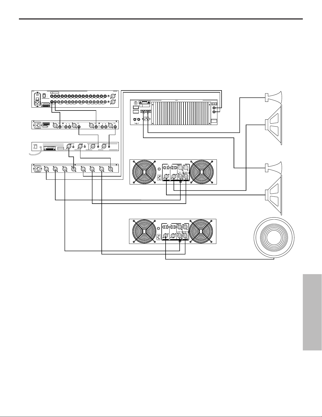
Instalaciones del sistema S•com
SISTEMA DE SONIDO EN DIRECTO CON COMPRESIÓN ESTÉREO
En este ejemplo, el S•com se ha insertado después del mezclador y antes del ecualizador
gráfico, con lo cual se comprime toda la gama de la señal procedente del mezclador.
57
ESPAÑOL
Mezclador PL1602
PL 1602
16 CHANNEL LINE MIXER
S / N
POWER
110
ON
OFF
AVIS:
RISQUE DE CHOC ELECTRIQUE
NE PAS OUVRIR
DO NOT EXPOSE THIS EQUIPMENT
TO RAIN OR MOISTURE
POWER
120V - 60 Hz 35W
RATING
RISK OF ELECTRIC SHOCK
~115V(0.3A)
230V(0.15A)
50/60Hz 30W
BUS
CAUTION
INSERTS
BALANCED 600 +4db
!
MIXER LINKING
DO NOT OPEN
TIP + RING - SLEEVE GND
S•Com
BALANCED
CAUTION
INPUT
RISK OF ELECTRIC SHOCK
DO NOT OPEN.
2
1
3
SERIAL NUMBER
MADE IN CHINA
_ mA SLOW BLOW FUSE FOR 115V
_ mA SLOW BLOW FUSE FOR 220V
Ecualizador dual
E30 de 15 bandas
E30 2/3 OCTAVE STEREO 15 BAND GRAPHIC EQUALIZER
AVIS: RISQUE DE CHOC ELECTRIQUE NE PAS OUVRIR. DO NOT EXPOSE
THIS EQUIPMENT TO RAIN OR MOISTURE.
ON
~AC INPUT
POWER
120V - 60 Hz 20W
RATING
OFF
POWER
115V/230V 50/60Hz13W
S•3 Way
SERIAL NUMBER
CAUTION
RISK OF ELECTRIC SHOCK
!
DO NOT OPEN
CH 2
HIGH
OUTPUT
2
2
1
1
CH 2
CH 2
MID
HIGH
3
3
OUTPUT
OUTPUT
MONO
MONO
HIGH-MID
HIGH
OUTPUT
OUTPUT
CHANNEL 2
+4
KEY
-10
INPUT OUTPUT
LEVEL
BALANCED <100Ω
0db UNITY GAIN
2
1
3
INPUTS BALANCED 10K‰ -30 to +4db TIP + RING - SLEEVE GND.
2R
1L2R3L4RLRLR
AUX
RETURNS
UNBALANCED
UNBALANCED 10K‰
BALANCED
OUTPUT
2
1
3
OUTPUTS
BALANCED
<100KΩ 0db
UNITY GAIN
CH 2
CH 2
INPUT
LOW
OUTPUT
2
1
CH 2
CH 2
LOW
INPUT
3
OUTPUT
SAMSON TECHNOLOGIES CORP., NEW YORK, U.S.A.
6R 5L 4R 3L 2R 1L
1L
AUX SEND
INSERTS TIP RETURN RING SEND
2K‰ +4db
XLR
PIN 1 GND
BALANCED
PIN 2 HOT
PIN 3 NEG
2
1
S com Plus
3
PHONE
TIP - POS
RING - NEG
SLEEVE - GND
BALANCED <100Ω
0db UNITY GAIN
BALANCED
<100KΩ 0db
UNITY GAIN
CH 1
HIGH
OUTPUT
2
2
1
1
CH 1
HIGH
3
3
OUTPUT
MIC 1
-10
2
3
0
1
-40+4
TRIM
1L2R3L4R5L6R7L8R9L10R11L12R13L14R15L16R
-10
3
0
-40+4
TRIM
MIC 3MAIN OUT
CHANNEL 1
+4
KEY
INPUT
BALANCED
0db UNITY GAIN
BALANCED
INPUT
-10
OUTPUT
2
1
LEVEL
3
INPUTS
BALANCED
0db UNITY GAIN
BALANCED
BALANCED
10KΩ
10KΩ
SAMSON
TECHNOLOGIES
CORP.,
NEW YORK, U.S.A.
CHANNEL ACHANNEL BCHANNEL ACHANNEL B
Amplificador de potencia Servo 550 (Altas)
2
1
OUTPUT
CAUTION
RISK OF ELECTRIC SHOCK
DO NOT OPEN
F
E
U
S
SERIAL
FUSE
NUMBER
FUSE RATING
12A/250V (115V)
6A/250V (230V)
USE CLASS 2 WIRING MAXIMUM LOAD IMPEDANCE 4Ω
CAUTION
HEATSINK MAY BE
HOT! DO NOT BLOCK
AIRFLOW OR OVER-
HEATING MAY OCCUR
TO PREVENT SHOCK DO
+RIGHT
NOT OPEN. NO USER
SERVICABLE PARTS
INSIDE. REFER SERVICING
TO QUALIFIED SERVICE
OUTPUT 250W/4Ω
PERSONNEL. TO PREVENT
FIRE OR SHOCK HAZARD
DO NOT EXPOSE TO RAIN
OR MOISTURE.
RIGHT
LEFT
115V/230W, 50/60HZ
510W (115V)900W (230V)
GROUND
~AC INPUT
SERVO 550 STUDIO AMPLIFIER
!
LEFT+
SAMSON TECHNOLOGIES CORP., HICKSVILLE, NEW YORK
TIP RING SLEEVE
BRIDGED
MONO STEREO
LEFT
RIGHT
INPUTS
(BALANCED
10KΩ/0dBm0)
TIP +
RING SLEEVE GND
Amplificador de potencia S1500 (Medias)
INPUT
CH 1
MID
OUTPUT
MONO
LOW-MID
OUTPUT
CHANNEL
STEREO
LOW
1 INPUT
3 WAY
3
3
OUTPUT
MONO
MONO
MONO
LOW
INPUT
4 WAY
OUTPUT
MODE
CHANNEL
CH 1
STEREO
1 INPUT
LOW
2 WAY
OUTPUT
2
2
1
1
CH 1
PUSH TO RESET
115V 60Hz, 920W
OUTPUT
20A/250V
(4Ω~8Ω) (4Ω~8Ω)
~AC INPUT
(4Ω~8Ω) (4Ω~8Ω)
CH 2 CH 1
BALANCED
0dBm
TRS
BALANCED
CH 2 CH 1
BRIDGED PARALLEL
STEREO
BALANCED
0dBm
TIP=HOT
3=COLD
XLR
RING=COLD
2=HOT
BALANCED
SLEEVE=GND
1=GND
Izquierda Altas/Medias
Derechas Altas/Medias
Amplificador de potencia S2000
(Puente mono, bajas)
INPUT
OUTPUT
PUSH TO RESET
25A/250V
115V 60Hz, 1100W
(4Ω~8Ω) (4Ω~8Ω)
~AC INPUT
(4Ω~8Ω) (4Ω~8Ω)
CH 2 CH 1
BALANCED
0dBm
TIP=HOT
TRS
RING=COLD
BALANCED
SLEEVE=GND
CH 2 CH 1
BRIDGED PARALLEL
STEREO
BALANCED
0dBm
3=COLD
XLR
2=HOT
BALANCED
1=GND
Sub
mono
Page 59
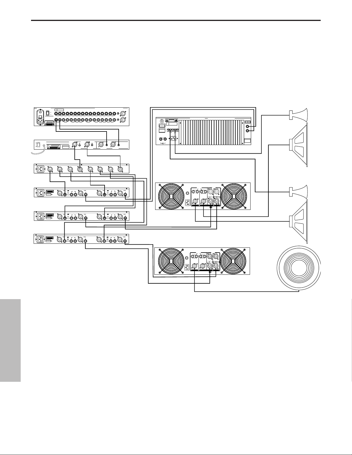
Instalaciones del sistema S•com
SISTEMA DE SONIDO EN DIRECTO CON COMPRESIÓN MULTIBANDA
En este ejemplo se han insertado tres S•com después del mezclador, el ecualizador y el
divisor de frecuencias, con lo cual pueden comprimirse de manera individual las frecuencias
bajas, medias-bajas, medias-altas y altas.
58
ESPAÑOL
Mezclador PL1602
PL 1602
16 CHANNEL LINE MIXER
S / N
POWER
110
ON
OFF
AVIS:
RISQUE DE CHOC ELECTRIQUE
NE PAS OUVRIR
DO NOT EXPOSE THIS EQUIPMENT
TO RAIN OR MOISTURE
POWER
120V - 60 Hz 35W
RATING
CAUTION
RISK OF ELECTRIC SHOCK
~115V(0.3A)
230V(0.15A)
50/60Hz 30W
BUS
INSERTS
BALANCED 600 +4db
!
MIXER LINKING
DO NOT OPEN
TIP + RING - SLEEVE GND
Ecualizador
E30 Dual 15 Band EQ
dual E30 de 15 bandas
E30 2/3 OCTAVE STEREO 15 BAND GRAPHIC EQUALIZER
AVIS: RISQUE DE CHOC ELECTRIQUE NE PAS OUVRIR. DO NOT EXPOSE
THIS EQUIPMENT TO RAIN OR MOISTURE.
ON
~AC INPUT
POWER
RATING
OFF
RISK OF ELECTRIC SHOCK
POWER
115V/230V 50/60Hz13W
S•3 Way
2
1
3
S•Com
CAUTION
RISK OF ELECTRIC SHOCK
DO NOT OPEN.
SERIAL NUMBER
MADE IN CHINA
_ mA SLOW BLOW FUSE FOR 115V
_ mA SLOW BLOW FUSE FOR 220V
S•Com
CAUTION
RISK OF ELECTRIC SHOCK
DO NOT OPEN.
SERIAL NUMBER
MADE IN CHINA
_ mA SLOW BLOW FUSE FOR 115V
_ mA SLOW BLOW FUSE FOR 220V
120V - 60 Hz 20W
CAUTION
DO NOT OPEN
BALANCED <100Ω
0db UNITY GAIN
SERIAL NUMBER
!
CH 2
HIGH
OUTPUT
2
2
1
1
CH 2
CH 2
MID
HIGH
3
3
OUTPUT
OUTPUT
MONO
MONO
HIGH-MID
HIGH
OUTPUT
OUTPUT
CHANNEL 2
+4
BALANCED
INPUT
-10
INPUT OUTPUT
2
1
LEVEL
3
CHANNEL 2
+4
BALANCED
INPUT
-10
INPUT OUTPUT
2
1
LEVEL
3
S•Com
CHANNEL 2
+4
BALANCED
CAUTION
INPUT
RISK OF ELECTRIC SHOCK
DO NOT OPEN.
SERIAL NUMBER
MADE IN CHINA
_ mA SLOW BLOW FUSE FOR 115V
_ mA SLOW BLOW FUSE FOR 220V
-10
INPUT OUTPUT
2
1
LEVEL
3
INPUTS BALANCED 10KΩ -30 to +4db TIP + RING - SLEEVE GND.
1L2R3L4RLRLR
AUX
RETURNS
UNBALANCED 10KΩ
OUTPUTS
BALANCED
<100KΩ 0db
UNITY GAIN
CH 2
CH 2
INPUT
LOW
OUTPUT
2
1
CH 2
CH 2
LOW
INPUT
3
OUTPUT
KEY
BALANCED
OUTPUT
2
1
3
KEY
BALANCED
OUTPUT
2
1
3
KEY
BALANCED
OUTPUT
2
1
3
SAMSON TECHNOLOGIES CORP., NEW YORK, U.S.A.
2R
6R 5L 4R 3L 2R 1L
1L
AUX SEND
INSERTS TIP RETURN RING SEND
UNBALANCED
2KΩ +4db
BALANCED <100Ω
0db UNITY GAIN
BALANCED
<100KΩ 0db
UNITY GAIN
CH 1
HIGH
OUTPUT
2
2
1
CH 1
HIGH
3
3
OUTPUT
XLR
PIN 1 GND
PIN 2 HOT
PIN 3 NEG
2
1
S com
3
PHONE
TIP - POS
RING - NEG
SLEEVE - GND
XLR
PIN 1 GND
PIN 2 HOT
PIN 3 NEG
2
1
S com
3
PHONE
TIP - POS
RING - NEG
SLEEVE - GND
XLR
PIN 1 GND
PIN 2 HOT
PIN 3 NEG
2
1
S com
3
PHONE
TIP - POS
RING - NEG
SLEEVE - GND
MIC 1
-10
2
3
0
1
-40+4
TRIM
1L2R3L4R5L6R7L8R9L10R11L12R13L14R15L16R
-10
2
3
0
1
-40+4
TRIM
MIC 3MAIN OUT
INPUTS
BALANCED
BALANCED
0db UNITY GAIN
0db UNITY GAIN
BALANCED
BALANCED
10KΩ
10KΩ
SAMSON
TECHNOLOGIES
CORP.,
NEW YORK, U.S.A.
CHANNEL ACHANNEL BCHANNEL ACHANNEL B
MODE
CHANNEL
CH 1
STEREO
1 INPUT
LOW
2 WAY
OUTPUT
2
2
1
1
1
CH 1
CH 1
MID
OUTPUT
MONO
LOW-MID
OUTPUT
CHANNEL
STEREO
LOW
1 INPUT
3 WAY
3
3
OUTPUT
MONO
MONO
MONO
LOW
INPUT
4 WAY
OUTPUT
Amplificador de potencia Servo 550 (Altas)
CAUTION
RISK OF ELECTRIC SHOCK
DO NOT OPEN
F
E
U
S
SERIAL
FUSE
NUMBER
FUSE RATING
12A/250V (115V)
6A/250V (230V)
USE CLASS 2 WIRING MAXIMUM LOAD IMPEDANCE 4Ω
CAUTION
HEATSINK MAY BE
HOT! DO NOT BLOCK
AIRFLOW OR OVERHEATING MAY OCCUR
TO PREVENT SHOCK DO
GROUND
+RIGHT
NOT OPEN. NO USER
SERVICABLE PARTS
INSIDE. REFER SERVICING
TO QUALIFIED SERVICE
OUTPUT 250W/4Ω
PERSONNEL. TO PREVENT
FIRE OR SHOCK HAZARD
DO NOT EXPOSE TO RAIN
OR MOISTURE.
RIGHT
~AC INPUT
LEFT
115V/230W, 50/60HZ
510W (115V)900W (230V)
SERVO 550 STUDIO AMPLIFIER
!
LEFT+
SAMSON TECHNOLOGIES CORP., HICKSVILLE, NEW YORK
BRIDGED
MONO STEREO
TIP RING SLEEVE
SLEEVE GND
LEFT
RIGHT
INPUTS
(BALANCED
10KΩ/0dBm0)
TIP +
RING -
Amplificador de potencia S1500 (Medias)
INPUT
CHANNEL 1
+4
KEY
BALANCED
INPUT
BALANCED
INPUT
BALANCED
INPUT
BALANCED
OUTPUT
INPUT
-10
OUTPUT
2
1
LEVEL
3
CHANNEL 1
+4
KEY
BALANCED
OUTPUT
INPUT
-10
OUTPUT
2
1
LEVEL
3
CHANNEL 1
+4
KEY
BALANCED
OUTPUT
INPUT
-10
OUTPUT
2
1
LEVEL
3
Amplificador de potencia S2000
PUSH TO RESET
115V 60Hz, 920W
OUTPUT
20A/250V
(4Ω~8Ω) (4Ω~8Ω)
~AC INPUT
(4Ω~8Ω) (4Ω~8Ω)
CH 2 CH 1
BALANCED
0dBm
TIP=HOT
TRS
RING=COLD
BALANCED
SLEEVE=GND
CH 2 CH 1
BRIDGED PARALLEL
STEREO
BALANCED
0dBm
3=COLD
XLR
2=HOT
BALANCED
1=GND
Izquierda Altas/Medias
Derecha Altas/Medias
(Puente mono, bajas)
INPUT
OUTPUT
PUSH TO RESET
25A/250V
115V 60Hz, 1100W
(4Ω~8Ω) (4Ω~8Ω)
~AC INPUT
(4Ω~8Ω) (4Ω~8Ω)
CH 2 CH 1
BALANCED
0dBm
TRS
BALANCED
CH 2 CH 1
BRIDGED PARALLEL
STEREO
BALANCED
0dBm
TIP=HOT
3=COLD
XLR
RING=COLD
2=HOT
BALANCED
SLEEVE=GND
1=GND
Sub
mono
Page 60
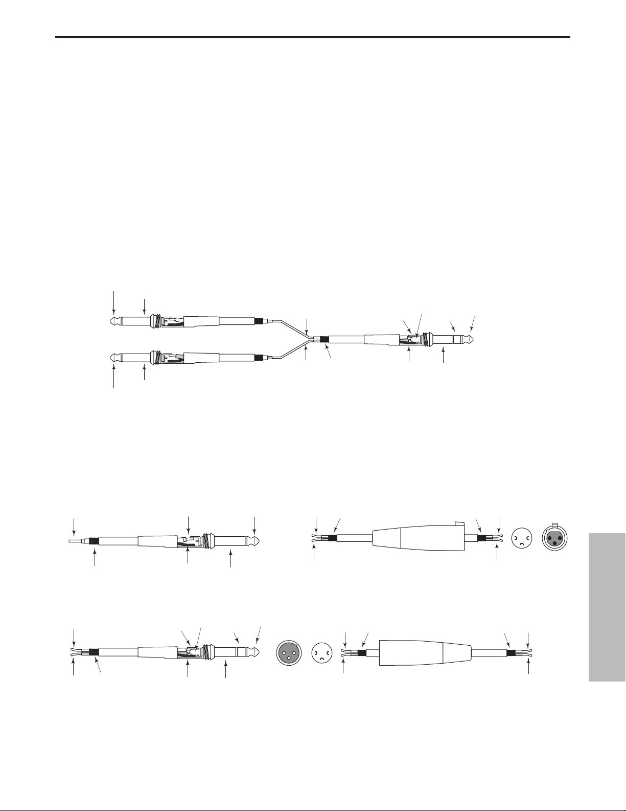
Conexiones del S•com
Conector de 1/4” no equilibrado
Cable de inserción de conector TRS macho de 1/4”a dos
machos de 1/4” en configuración de envío y retorno.
Guía de cableado XLR equilibrada
CONECTAR EL S•com
Existen diversas maneras de conectar el S•com para diferentes aplicaciones. El S•com dispone de entradas y salidas
servoequilibradas, con lo cual es posible conectar señales equilibradas y no equilibradas sin ninguna pérdida de señal. El
S•com puede utilizarse en un único instrumento conectándolo a los puntos de inserción de un canal, o a toda una mezcla
"en línea" entre las salidas de un mezclador y un amplificador de potencia o un ecualizador.
PUNTOS DE INSERCIÓN
Muchos mezcladores actuales permiten inserciones de canal y de bus o grupo. Los puntos de inserción son puntos de
entrada y de salida que interrumpen la señal del canal o del bus para poder conectar procesadores externos. Los puntos de
inserción de canal son ideales para la conexión cuando se utiliza el S•com para procesar un único canal, como una parte
vocal, de bajo o de guitarra. Los puntos de inserción de bus son ideales para comprimir grupos de instrumentos, como partes
vocales, cuerdas o percusión. Si se conecta a los puntos de inserción de un canal, puede tener un único jack TRS para Envío
y Retorno. En este caso, utilice un cable de inserción en "Y" configurado como el del siguiente esquema de cableado.
a
EN LÍNEA
En las aplicaciones de sonido en directo, el S•com puede instalarse en línea entre un mezclador y un
ecualizador o amplificador de potencia. Para estas aplicaciones, el S•com dispone tanto de conectores TRS de
1/4" como de conectores XLR para poder interactuar de manera muy sencilla con la mayoría de los equipos de
audio profesionales. Siga los ejemplos de cableado de la figura inferior para su instalación concreta.
Conector TRS de 1/4”equilibrado
59
ESPAÑOL
Punta (envío)
Funda (común)
Emvío (punta)
Retorno (anillo)
Envío (punta)
Anillo (retorno)
Punta (envío)
Común
Punta (retorno)
Funda (común)
Retorno
(anillo)
Común
Funda (común)
Señal
Masa
Señal (punta)
Señal (anillo)
Masa
Masa
Señal (anillo)
Señal (punta)
Masa
Funda (masa)
Anillo (señal)
Funda (masa)
Punta (señal)Señal
Punta (señ
Excitado
12
3
Vista
exterior
Frío
2
3
Puntos de
soldadura
Excitado (2)
1
Frío (3)
Común (1)
XLR hembra
XLR macho
Excitado (2)
Común (1)Común
1
2
21
3
Puntos de
Vista exterior
soldadura
Frío (3)
Excitado
Común
Frío
3
Page 61

Specifications
System Specifications
Frequency Response <10Hz to 20kHz +0 / -0.1 dB effect out, -0.4 @ 100kHz,
<10Hz to 20kHz +0 / -0.1 dB effect in, -3dB @ >100kHz
Dynamic range 116dBu, un-weighted, 22 Hz to 22 kHz
THD 0.008 % typ. @ +4 dBu, 1 kHz Effect out, 0.016% effect in
Crosstalk >95dB, 22 Hz to 22 kHz
Operating Level Selectable +4dBu / -10 dBV
Max. Input Level +21dBu, balanced
CMRR Min 40dB, >50dB @ 1kHz
Max. Output Level +21dBu Balanced
Balanced Input
Connectors XLR and 1/4" TRS jack
Impedance >20k Ohm balanced or unbalanced
Balanced Output
Connectors XLR and 1/4" jack
Impedance 60 Ohms balanced or unbalanced
K
ey Input
Connector 1/4" jack
Impedance 10 k Ohm
Max. Input Level +21 dBu
K
ey Output
Connector 1/4" jack
Impedance 47 Ohms
Max. Output Level +21 dBu
Expander/Gate
Trigger range Variable (Off to +10 dB)
Attack <1 ms per 50 dB
Release Variable (Slow:100 ms / 1dB, Fast:100 ms / 100 dB)
Ratio Expander 1:2, Gate 1:16
Compressor Section
Detector RMS
Threshold -40 dB to +20 dB
Ratio Variable (1:1 to infinity:1)
Manual Attack Time Variable (0.3 ms / 20 dB to 300 ms / 20 dB)
Manual ReleaseTime Variable (0.05 to 5 Sec)
Output gain Variable (-20 to +20 dB)
Enhancer off to 10
Function Switches
Gate Gate or Expander
Release Fast/slow
Spectra 15dB gain reduction @ 1K
Key Switches the detector section to external key input.
Key Listen Connects the External Key Input to the Balanced Output for monitoring
Auto Sets automatic attack and release times and automated timing - program dependent
I/O Meter Switches the Input/Output meter to read input or output level .
Stereo Link Links both channels for stereo operation. Channel 1 becomes master.
Operating Level (Rear Panel) Changes the internal reference level from-4 dBu to -10 dBV.
60
Page 62

Meters & LED's
Gain Reduction 12 segment LED display:
30 / 27 / 24 / 21 / 18 / 15 / 12 / 9 / 6 / 4 / 2 / 1 dB
Input/Output level 12 segment LED display:
-30 / -24 / -18 / -12 / -6 / -3 / 0 / +3 / +6 / +9 / +12 / +18dB
Expander/Gate Threshold 2 LED's Gate open, Gate closed
Function switch LED indicator in each (except Operating Level)
P
ower Supply
Mains Voltages USA/Canada 105-125 VAC ~, 60 Hz
Mains Voltages Europe 215 – 254 VAC~,50Hz
Power Consumption 10 Watts
Power inlet Standard IEC receptacle/with fuse
Ph
ysical
Dimensions 1 3/4" (44.5 mm) x 19" (482.6 mm) x 7 3/4" (197 mm)
Net Weight 4.8 lbs (2.2 kg)
Shipping Weight 7.5 lbs (3.4 kgs)
Specifications
61
Page 63
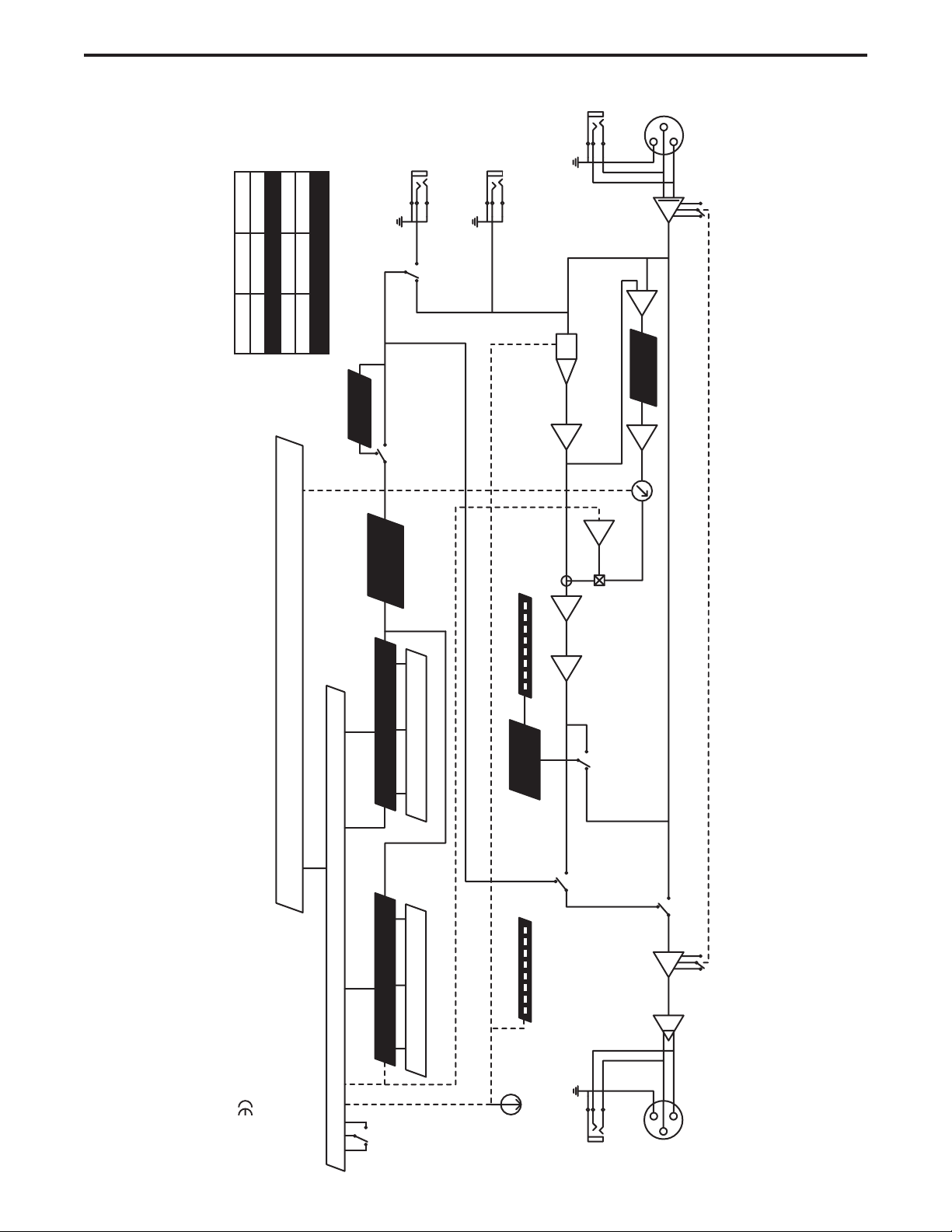
Block Diagram
62
GND
HOT
TIP
CONNECTIONS
PIN 1 PIN 2
KEY INPUT
EXTERNAL
OUTPUT
KEY
INPUT
-10dBv
or
-10dBv
+4dBu
I/O LEVEL
COLD GND
EXTERNAL
1/4"
RING SLEEVE
XLR
HOT COLD
PIN 3
SPECTRA
FILTER
OUT
IN
CHANNEL 2 IS IDENTICAL TO CHANNEL 1 EXCEPT FOR STEREO LINK MODE
CONVERTOR
RMS to DC
INTERNAL
SPECTRA
SOURCE
KEY
VCA DC CONTROL
METER
I/O LEVEL
+4dBu
VCA
COMPARATOR
ENHANCER
FILTER
LEVEL
ENHANCER
∑
STEREO LINK
IN OUT
COMPRESSOR CONTROL
COMPRESSOR
EXPANDER/GATE
GATE CONTROL
STEREO
LINK
FULL WAVE
RECTIFIER
GAIN REDUCTION
METER
OUTPUT
LEVEL
OUTPUT
SOURCE
METER
INPUT
OUT
LISTEN
KEY
IN
OUTPUT
BYPASS
IN
OUT
-10dBv
+4dBu
-10dBv
or
I/O LEVEL
+4dBu
Page 64

Samson Technologies Corp.
575 Underhill Blvd.
P.O. Box 9031
Syosset, NY 11791-9031
Phone: 1-800-3-SAMSON (1-800-372-6766)
Fax: 516-364-3888
www.samsontech.com
scomomv2
 Loading...