

Page 1

Page 2
Safety Instructions/Consignes de sécurité/Sicherheitsvorkehrungen/Instrucciones de seguridad
ACHTUNG:
Sie dieses Gerät weder Regen noch Feuchtigkeit aussetzen.Um die Gefahr eines
Stromschlags zu verringern, sollten Sie weder Deckel noch Rückwand des Geräts ent-
fernen. Im Innern befinden sich keine Teile, die vom Anwender gewartet werden kön-
nen. Überlassen Sie die Wartung
qualifiziertem Fachpersonal.
gleichseitigen Dreieck soll den Anwender vor nichtisolierter “gefährlicher Spannung”
im Geräteinnern warnen. Diese Spannung kann so hoch sein, dass die Gefahr eines
Stromschlags besteht. Das Ausrufezeichen im gleichseitigen Dreieck soll den Anwender
auf wichtige Bedienungs- und Wartungsan leitungen aufmerksam machen, die im mit-
gelieferten Informationsmaterial näher beschrieben werden.
Wichtige Sicherheitsvorkehrungen
2. Bewahren Sie diese Anleitungen für den späteren Gebrauch gut auf.
3. Bitte treffen Sie alle beschriebenen Sicherheitsvorkehrungen.
4. Befolgen Sie die Anleitungen des Herstellers.
5. Benutzen Sie das Gerät nicht in der Nähe von Wasser oder Feuchtigkeit.
6. Verwenden Sie zur Reinigung des Geräts nur ein feuchtes Tuch.
7. Blockieren Sie keine Belüftungsöffnungen. Nehmen Sie den Einbau des Geräts nur
entsprechend den Anweisungen des Herstellers vor.
8. Bauen Sie das Gerät nicht in der Nähe von Wärmequellen wie Heizkörpern,
Wärmeklappen, Öfen oder anderen Geräten (inklusive Verstärkern) ein, die Hitze
erzeugen.
9. Setzen Sie die Sicherheitsfunktion des polarisierten oder geerdeten Steckers nicht
außer Kraft. Ein polarisierter Stecker hat zwei flache, unterschiedlich breite Pole. Ein
geerdeter Stecker hat zwei flache Pole und einen dritten Erdungsstift. Der breitere
zen.
es nicht geknickt werden kann. Achten Sie hierbei besonders auf Netzstecker,
Mehrfachsteckdosen und den Kabelanschluss am Gerät.
aus der Steckdose.
wendig, wenn das Gerät auf irgendeine Weise, beispielsweise am Kabel oder
gelangt sind, es Regen oder Feuchtigkeit ausgesetzt war, nicht mehr wie gewohnt
betrieben werden kann oder fallen gelassen wurde.
WARNING
: To reduce the risk of fire or electric shock, do not expose this unit to rain
or moisture. To reduce the hazard of electrical shock, do not remove cover or back.
alert the user to the presence of uninsulated "dangerous voltage" within the products
enclosure that may be of sufficient magnitude to constitute a risk of electric shock to
persons. The exclamation point within an equilateral triangle is intended to alert the
user to the presence of important operating and maintenance (servicing) instructions
in the literature accompanying the product.
Important Safety Instructions
2. Keep these instructions for future reference.
3. Please heed all safety warnings.
4. Follow manufacturers instructions.
5. Do not use this unit near water or moisture.
6. Clean only with a damp cloth.
7. Do not block any of the ventilation openings. Install in accordance with the manu-
facturers instructions.
8. Do not install near any heat sources such as radiators, heat registers, stoves, or
other apparatus (including amplifiers) that produce heat.
9. Do not defeat the safety purpose of the polarized or grounding-type plug. A polar-
ized plug has two blades with one wider than the other. A grounding type plug has
two blades and a third grounding prong. The wide blade or third prong is provided
for your safety. When the provided plug does not fit your outlet, consult an electri-
cian for replacement of the obsolete outlet.
convenience receptacles and at the point at which they exit from the unit.
been damaged in any way, such as power supply cord or plug damage, or if liquid
rain or moisture, does not operate normally, or has been dropped.
PRECAUCION
: Para reducir el riesgo de incendios o descargas, no permita que este
aparato quede expuesto a la lluvia o la humedad. Para reducir el riesgo de descarga
eléctrica, nunca quite la tapa ni el chasis. Dentro del aparato no hay piezas susceptibles
de ser reparadas por el usuario. Dirija cualquier reparación al servicio técnico oficial. El
símbolo del relámpago dentro del triángulo equilátero pretende advertir al usuario de
pueden ser de la magnitud suficiente como para constituir un riesgo de descarga eléc-
trica a las personas. El símbolo de exclamación dentro del triángulo equilátero quiere
advertirle de la existencia de importantes instrucciones de manejo y mantenimiento
(reparaciones) en los documentos que se adjuntan con este aparato.
Instrucciones importantes de seguridad
2. Conserve estas instrucciones para cualquier consulta en el futuro.
3. Cumpla con todo lo indicado en las precauciones de seguridad.
4. Observe y siga todas las instrucciones del fabricante.
5. Nunca utilice este aparato cerca del agua o en lugares húmedos.
6. Limpie este aparato solo con un trapo suave y ligeramente humedecido.
7. No bloquee ninguna de las aberturas de ventilación. Instale este aparato de acu-
erdo a las instrucciones del fabricante.
8. No instale este aparato cerca de fuentes de calor como radiadores, calentadores,
9. No anule el sistema de seguridad del enchufe de tipo polarizado o con toma de
tierra. Un enchufe polarizado tiene dos bornes, uno más ancho que el otro. Uno
con toma de tierra tiene dos bornes normales y un tercero para la conexión a
tierra. El borne ancho o el tercero se incluyen como medida de seguridad. Cuando
el enchufe no encaje en su salida de corriente, llame a un electricista para que le
cambie su salida anticuada.
o aplastado, especialmente en los enchufes, receptáculos y en el punto en el que
salen de la unidad.
no lo vaya a usar durante un periodo de tiempo largo.
su aparato sea reparado cuando esté dañado de alguna forma, como si el cable de
corriente o el enchufe están dañados, o si se han derramado líquidos o se ha intro-
ducido algún objeto dentro de la unidad, si esta ha quedado expuesta a la lluvia o
ATTENTION:
Pour éviter tout risque d’électrocution ou d’incendie, ne pas exposer
cet appareil à la pluie ou à l’humidité.
Pour éviter tout risque d’électrocution, ne pas
ôter le couvercle ou le dos du boîtier.
Cet appareil ne contient aucune pièce rem-
plaçable par l'utilisateur. Confiez toutes les réparations à un personnel qualifié.
tension dangereuse et non isolée dans l’appareil. Cette tension constitue un risque
d’électrocution. Le signe avec un point d’exclamation dans un triangle prévient
produit.
Consignes de sécurité importantes
2. Conserver ces instructions pour toute lecture ultérieure.
3. Lisez avec attention toutes les consignes de sécurité.
4. Suivez les instructions du fabricant.
5. Ne pas utiliser cet appareil près d’une source liquide ou dans un lieu humide.
6. Nettoyez l’appareil uniquement avec un tissu humide.
7. Veillez à ne pas obstruer les fentes prévues pour la ventilation de l’appareil.
8. Ne pas installer près d’une source de chaleur (radiateurs, etc.) ou de tout équi-
pement susceptible de générer de la chaleur (amplificateurs de puissance par
exemple).
9. Ne pas retirer la terre du cordon secteur ou de la prise murale. Les fiches cana-
diennes avec polarisation (avec une lame plus large) ne doivent pas être modi-
fiées. Si votre prise murale ne correspond pas au modèle fourni, consultez votre
électricien.
tension, torsion,, etc.). Veillez à ce que le cordon secteur soit libre, en particulier à
sa sortie du boîtier.
d’inutilisation prolongées.
mage sur le cordon secteur, baisse de performances, exposition à la pluie, pro-
jection liquide dans l’appareil, introduction d’un objet dans le boîtier, etc.).
Page 3

Copyright 2005, Samson Technologies Corp.
Samson Technologies Corp.
575 Underhill Blvd.
Syosset, NY 11791-9031
Table of Contents
Servo Series Features 3
Guided Tour 4-5
Front Panel 4
Setting Up and Using Your Servo Series 6
The Servo Series Protection Circuitry 7
Servo Series Connections 9
Specifications 10
Appendix A: Power Output vs. THD 11
Appendix B: Frequency Response 12
Page 4

2
Thank you for purchasing the Servo Series Power Amplifier from Samson Audio! We know you don’t like reading own-
Thank you for purchasing the Servo Series Power Amplifier from Samson Audio! We know you don’t like reading own-
ers manuals, but you’ve just purchased one of the finest sound reinforcement power amplifiers around, and we want
to tell you about it. So, before you plug in, we’d like to suggest you take just a few moments out to scan these pages.
We’ll make it as painless as possible, we promise—and, who knows, you might just pick up a tip or two.
The Samson Servo Series stereo power amplifiers have been designed to provide robust, clean output with low distor-
The Samson Servo Series stereo power amplifiers have been designed to provide robust, clean output with low distor-
tion and wide dynamic range, along with the dependability demanded by the most professional audio engineers and
Their convenient 2 rack-space design is compact, and yet there’s plenty of power available, with 2 x 66 Watts at 8Ω, 2
Their convenient 2 rack-space design is compact, and yet there’s plenty of power available, with 2 x 66 Watts at 8Ω, 2
x 100 Watts at 4Ω for the Servo 200, 2 x 100 Watts at 8Ω, 2 x 150 Watts at 4Ω for the Servo 300, 2 x 225 Watts at 8Ω, 2 x
300 Watts at 4Ω for the Servo 600, over the full frequency spectrum, from 10 Hz to 55 kHz.
a 8 ohms load.
and
the outputs, the Servo Series amplifiers provide standard 5-way binding posts and 1/4” phone jacks. Front-panel con-
trols and displays include a power switch with LED indicator, as well as independent left and right channel input level
controls. To help you set the correct operating levels, the Servo Series amplifiers include front panel Signal, Peak
and
ten-segment Level VU meter to help you set a good operating level.
over-sized toroidal transformers and large extruded heat sinks. To keep the
Servo Series
amplifiers running cool, their
design employs twin internal wind tunnels with forced-air cooling via two temperature-sensitive, variable speed fans,
which greatly reduce the chance of thermal and overheating problems. Multi-stage protection for power-up, over-
demanding situations.
The
The
Servo Series
amps are road tough with their all steel chassis and19-inch rack mount design. The
Servo Series
amplifiers are ready for a life on the road, or to make their home in a nice fixed installation.
Optimized for live sound venues, houses of worship, commercial installations, and for driving small and medium-sized
Servo Series
amplifiers will deliver reliable power from gig-to-gig, venue-to-venue and day-to-
a guided tour through its front and rear panels, step-by-step instructions for its setup and use, and full specifications.
You’ll also find a warranty card enclosed—please don’t forget to fill it out and mail it in so that you can receive online
technical support and so we can send you updated information about these and other Samson products in the future.
SPECIAL NOTE: Should your Servo Series ever require servicing, a
number (RA) is necessary.
Without this number, the unit will not be accepted. If purchased in the United States, please call Samson at 1-800-372-
6766 for a Return Authorization number prior to shipping the unit. If purchased outside the United States, contact
your local Samson dealer for details. Please retain the original packing materials and, if possible, return the unit in its
original carton and packing materials.
Page 5
3
The Samson Servo Series power amplifier utilizes the latest technology in professional power amplifier design. Here are some of
• Power to spare - Each amplifier delivers the following power ratings.
Servo 200 2 x 66 Watts at
8Ω,
2 x
W
atts at
4
Ω
Servo 300 2 x 100 Watts at
8Ω,
atts at
Servo 600 2 x 225 Watts at
8Ω,
300
atts at
• For mono applications, a Bridge mode links both channels of the amplifiers, thus providing even more power, with power rat-
Servo 200,
300
watts for the
Servo 300,
and
600
watts for the
Servo 600,
all driving an 8 Ohm load.
• Clean, crisp sound - Impressive audio specifications such as 0.04% THD, dynamic range of 105 dB, crosstalk of 80 dB, and fre-
quency response of 10 Hz to 55 kHz guarantee ultra-clean sound quality.
• Independent input level controls for each channel allow precision adjustments.
• 10 segment LED signal indicators for each channel continuously display power output levels and allow you to correct for
overloading (clipping) conditions.
• Unique stable bipolar circuit design that continuously keeps DC output during idling at or near zero volts (thus keeping idle
speakers at their zero point). This serves to minimize heat overload problems by effectively preventing the Servo Series from
applying power when unnecessary.
• Forced air cooling via two temperature-sensitive, variable speed fans provides reliable performance without thermal and
overheating problems.
• Protection relay circuitry (with dedicated LEDs for each channel) that guards against overheating or faulty wiring conditions
and also prevents “thumps” when powering on or off. This means that you can use the Servo Series with a single power strip
• Input connectors for each channel accommodate both RCA or balanced 1/4-inch TRS plugs.
• Output connections are made via 5-way binding posts
.
• Toroidal transformer power supply for high current and low profile.
• User-resettable circuit breaker for fast, easy startup following a power supply overload.
• The Servo Series can be mounted in any standard 19" rack (taking just two rack spaces), making it easy to integrate the amp
• Rugged construction (an all-steel chassis with a cool gray finish and a lightweight anodized aluminum heat sink) makes the
Servo Series eminently roadworthy.
• Extended three-year warranty.
• Last but certainly not least, value. The Samson Servo Series has been designed from the ground up to deliver excellent yet
affordable sound quality
Page 6

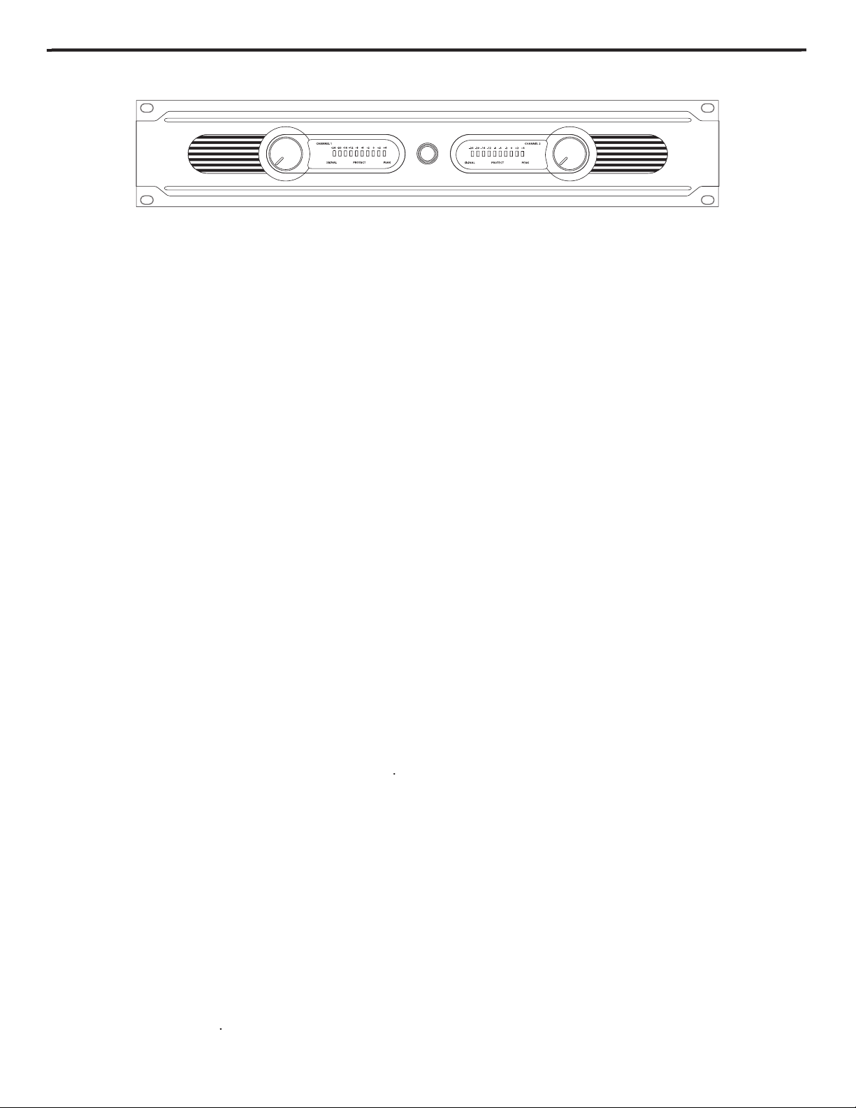
- The Servo Series amplifiers stay cool thanks to their twin, forced-air cooling tunnels. Cool air is drawn through
the front panel fan vents, reducing the temperature of the internal components while forcing the heat out the rear vents.
The fans will actually sense the internal temperature and adjust their speed to maintain the optimum cooling conditions.
2: Channel input level controls
- These 42-position detented controls allow you to precisely adjust the input level of the
signal arriving at the rear-panel input jacks (see #1 and #5 on the following page). At their fully counterclockwise posi-
tion (labeled “MIN”), the signal is attenuated by 80 dB (essentially completely off). At their fully clockwise position (labeled
“MAX”), the signal is at unity gain (that is, no attenuation). When +4 dBu of signal arrives at the input jacks and the Channel
3: LED meters
- These ten-segment LED meters continuously monitor the power output level for the corresponding chan-
and +4 dB (PEAK). The right (PEAK) segment lights whenever the channel is outputting signal at full strength. For the best
signal-to-noise ratio, the right (PEAK) segment should light occasionally during peak levels; if it lights frequently, you may
4: Power switch
- Use this to power the Servo Series on or off. The internal LED lights whenever the Servo Series is powered
on.
5: Signal LED
- The front panel LED indicators continuously monitor the power output level for the corresponding channel.
The SIGNAL LED lights whenever output signal is present.
6: Protection LED
- This goes on for approximately five seconds whenever the Servo Series is powered on and then turns
off (you’ll hear a “click” when it does so). The Protection LED will also light when overheating or other severe problems occur
ered off. When lit, no signal is provided to any connected speakers, thus muting them and preventing any “thump” from
occurring. For a complete description of the conditions under which this light goes on, see the section entitled “The Servo
Series Protection Circuitry” on page 7 of this manual.
7: Peak LED
- The PEAK segment lights whenever the channel is outputting signal at full strength. For the best signal-
to-noise ratio, the right (PEAK) segment should light occasionally during peak levels; if it lights frequently, you may be
overloading the Servo Series and a distorted (“clipped”) signal is probably being output. If this occurs and backing off the
4
Page 7

5
– You can connect unbalanced incoming signals to the Servo series using the RCA connectors, which
are wired as follows: Pin 2 (or Tip) hot, and Pin 1 (or Sleeve) ground. The Servo Series accepts input levels of any strength but
2 input jacks; however, when operating the Servo Series in Bridged mode, use the Channel 1 input jack only. See page 8 in this
2: Fan
- This variable-speed fan provides vital cooling to your Servo Series (the hotter the amp gets, the faster the fan blows!).
Also, try to ensure that the Servo Series is used in a dust-free environment.
3: 1/4-inch Output Connectors
- Use these to connect each channel of the Servo Series to, 4-ohm or 8-ohm loudspeakers with
speaker connection instructions.
4: 5-way Binding Post
- Use these to connect each channel of the Servo Series to 4-ohm or 8-ohm loudspeakers. Be sure to con-
about Bridge mode and page 9 in this manual for full speaker connection instructions
5: 1/4-inch Input Connectors
- Connect incoming signals to these electronically balanced inputs, using the 1/4” TRS (Tip/Ring/
Sleeve) plugs, wired as follows: Pin 2 (or Tip) hot, Pin 3 (or Ring) cold, and Pin 1 (or Sleeve) ground. We recommend the use of bal-
anced three-conductor cabling wherever possible (unbalanced two-conductor 1/4” plugs can also be inserted into these inputs,
of any strength but needs at least +4 dBu to achieve maximum power. Stereo signals should be connected to both the Channel
6: AC input
- Connect the supplied heavy-gauge 3-pin “IEC” power cable here.
7: Bridge / Stereo switch
- For normal operation, place this two-way switch in its lower (“STEREO”) position. When placed in its
Channel 2 input is ignored), but the two power amplifiers are bridged together. For more information, see the “Bridge Mode”
section on page 8 in this manual and the “Servo Series Connections” section on page 9 in this manual. WARNING: Due to the
extremely high power output of the Servo Series when used in Bridge mode, be sure to use only loudspeakers sufficiently rated to
Page 8

6
Bridge / Stereo switch
Output connectors
Input connectors
Protection LED
Channel Input control
Setting up your Servo Series is a simple procedure which takes only a few minutes:
amplifier is to be physically placed—it can be used free-standing or mounted in a standard 19” rack,
spacer panels, especially if multiple amplifiers are used in a rack.)
2. Set the rear panel Bridge/ Stereo switch as desired (see the “Bridge Mode” section on page 8 in this
3. Make the speaker connections, using the banana or 1/4-inch output connectors on the rear panel.
ating in Stereo mode, any loudspeakers with a minimum impedance load of 4 ohms (that is, 4 ohms
or greater) can be used; however, in Bridged mode, 16 or 8 ohm speakers must be used. Be sure to
connect the loudspeaker correctly. In Stereo mode, make sure the red (+) terminal is connected to
the positive input of the speaker and the black (ground) terminal is connected to the negative input
of the speaker. See page 8 in this manual for more information about Bridged mode and page 9 in
this manual for full speaker interconnection instructions.
4. Next, make the signal input connections, using the RCA or 1/4-inch input connectors on the rear
this manual for more information). If your mixer or crossover network has balanced outputs, we rec-
ommend the use of three-conductor cabling and connectors (unbalanced two-conductor plugs can
also be inserted into the 1/4-inch inputs, but you’ll get better signal quality and less outside noise
and hum if you use balanced lines).
5. On the front panel of the Servo Series, turn both Channel input controls fully counterclockwise (to
their “MIN” setting). Then connect the supplied heavy-gauge 3-pin “IEC” cable to the rear panel IEC
connector and to any grounded AC socket.
same power strip that other audio devices (such as a mixing console) are connected to. You can then
turn on all devices at once with the single power strip on-off switch, with no danger of damaging
connected speakers by generating “thumps.”
6. Press the front panel Power switch in order to turn on the Servo Series. The Power LED will light
and the Protection LED will go on. After approximately five seconds, the Protection LED will go off
the output meters at approximately 0 vu). While the input signal is present, slowly raise the Channel
each Channel input control will show you the continuous power output of the Servo Series as signal
Channel Input controls at or near maximum (fully clockwise, at the “MAX” position) and the PEAK
segments should light occasionally (but not frequently) during peak levels. If you are using a mixer
that has a master output level control (sometimes called “control room level”), use it to attenuate the
signal as necessary to achieve the desired speaker level.
cal Samson dealer. If purchased in the United States, you can call Samson Technical Support (1-800-
372-6766) between 9 AM and 5 PM EST
Page 9

The Servo Series Protection Circuitry
As noted in the “Guided Tour” section of this manual, the Servo Series front-panel
the Protection LED is lit, this circuitry is active, and all connected speakers are muted
from occurring.
The following conditions will cause the Protection LED to go on:
• Initial power-up:
For approximately five seconds after initial power-up, the protec-
tion circuitry is activated and the speaker outputs are muted. If everything is operat-
the protection circuitry is deactivated and the Servo Series begins delivering signal to
connected speakers (at which point you’ll hear a click). It is normal for the Protection
•
Overheating:
A temperature sensing device in the Servo Series will cause the protec-
tion circuitry to be activated (and the Protection LED to go on) whenever the operat-
the front and rear panels are unobstructed.
• Severe overcurrent conditions:
This occurs whenever the signal being output from the
Servo Series rises to a level above 20% THD (Total Harmonic Distortion).
• Shorted speaker cables:
This will occur if, due to faulty wiring, the hot and ground sig-
• Output impedance drops below 4 ohms
: This can occur if the Servo Series is connect-
ed to inappropriate speaker systems (see the “Setting Up and Using Your Servo Series”
section on page 6 in this manual for more information).
• DC voltage detected at speaker output
: The most likely cause of this is an internal fail-
occurs, turn the Servo Series off immediately and carefully check all wiring and exter-
States, you can call Samson Technical Support (1-800-372-6766) between 9 AM and 5
WARNING: If the Protection LED fails to go out (and you fail to hear the accom-
Servo Series off immediately and check all external devices and wiring for pos-
sible shorts or other defects.
Page 10

8
The Servo Series provides a rear-panel switch that allows it to be used in either Stereo
or Bridge mode. When this switch is placed in the “STEREO” (down) position, the
Servo Series functions as a true stereo amplifier, where both of the two independent
amplifier channels (Channel 1 and Channel 2) can receive different input signals and
“BRIDGE” (up) position, the Channel 1 input signal is routed to both power amplifiers
watts for the Servo 300, and 600 watts for the Servo 600.
The illustration on the right shows how this works. In Bridged mode, the polarity
connected so that power is derived from both channels. The effective voltage swing
seen by the load is thus doubled, so that the power output is multiplied by more than
two.
When using the Servo Series in Bridge mode, be sure to connect your loudspeaker
as shown in the illustrations on page 9 (and as silkscreened on the rear panel), with
the red (+) terminal of the Channel 1 output connected to the positive input of the
speaker and the red (+) terminal of the Channel 2 output connected to the negative
See pages 9 in this manual for interconnection diagrams when using the Servo Series
WARNING: Bridge mode is to be used only when the Servo Series is connected
to an 8 ohm speaker load. Use of Bridged mode with speaker loads of 4 ohms
or less can result in severe damage to the unit due to excessive heat and current
INPUT
CHANNEL
1(+) OUTPUT
CHANNEL
2(+) OUTPUT
Bridge Mode
Page 11

The illustrations on this page show the required
Stereo and Bridged modes.
9
+-
-+
(4 ohm min)
(4 ohm min)
+-
-+
(4 ohm min)
(4 ohm min)
�
+
-
-
+
+
-
+
-
(8 ohm min)
(8 ohm min)
(8 ohm min) (8 ohm min)
MPL2242
MMPL2242
Page 12

Servo 200 Servo 300 Servo 600
Servo 200 Servo 300 Servo 600
Stereo both channel driven
8 ohms 66 Watts x 2 100 Watts x 2 225 Watts x 2
4 ohms 100 Watts x 2 150 Watts x 2 300 Watts x 2
Bridged mono
8 ohms 200 Watts 300 Watts 600 Watts
Signal to Noise Ratio (20Hz-20k) 102dB 102dB 104dB
Voltage Gain 32dB 33dB 34dB
Output Circuitry AB AB AB
AC Power @1/8 rated power 4ohms, max. 0.5A 0.7A 1.3A
AC Power @1/3 rated power 4ohms, max. 1.1A 1.7A 3.3A
AC Power @ rated power 4ohms, max. 3.3A 5.0A 10A
20Hz-20kHz,10dB below rated power 0.01% 0.01% 0.03%
IkHz,rated power 0.1% 0.1% 0.1%
Cooling Continuously variable speed, fan forced air
Connectors (each channel)
Input: RCA unbalanced and1/4”(6.3mm)TRS, balanced
Output: 5-way Binding post and 1/4” Phone
Controls AC power switch,Channel 1 and 2 volume
Signal(green) for each Ch.,Peak(red) for each Ch.
Level: , -24 dB, -20 dB, -16 dB, -12 dB, -8 dB, -4 dB, -2 dB. O, +2 dB and +4 dB
Net Weight 15 lbs 6.82 kg 20 lbs 9.09 kg 24 lbs 10.91 kg
Page 13

Appendix A: Power Output vs. THD
0
1
0.05
0.1
0.15
0.2
0.25
0.3
0.35
0.4
0.45
0.5
0.55
0.6
0.65
0.7
0.75
0.8
0.85
0.9
0.95
0
125
5
10
15
20
25
30
35
40
45
50
55
60
65
70
75
80
85
90
95
100
105
110
115
120
10 50k20 50 100 200 500 1k 2k 5k 10k 20k
THD %
Servo 600
Servo 300
Servo 200
Page 14

Appendix B: Frequency Response
5.0000
4.0000
3.0000
2.0000
1.0000
0.0
-1.000
-2.000
-3.000
-4.000
-5.000
10
100
1k
10k
50k
Ap
AUDIO PRECISION Servo 600 LEVEL (dBr) vs FREQ (Hz)
0dB ref
Page 15

Page 16

Samson Technologies Corp.
575 Underhill Blvd.
Syosset, NY 11791-9031
www.samsontech.com
 Loading...