

Page 1
®
OWNERS MANUAL
SPEAKER DISTRIBUTION SYSTEM
Page 2

Introduction 3
DS70 Features 3
Guided Tour 4
Modes of Operation 5
Wiring Diagrams 6
Four-Zone 70V (Unbridged) 6
Two-Zone 70V (Bridged) 7
Four-Zone 25.2V (Unbridged) 8
Two-Zone 100V (Bridged) 9
Two-Zone 140V (Bridged) 10
Appendix A: Block Diagram 11
Specifications 12
Page 3

Introduction / DS70 Features
Congratulations on purchasing the Samson DS70 Speaker Distribution System!
The DS70 provides four high-quality toroidal step-up transformers in a single chassis.
Each transformer can accept a nominal-level signal from any standard power amplifier,
and can then convert it to a 70 volt, 25.2 volt, or 100 volt line-level output for use in
paging and public address systems and wherever long cable runs and multiple speakers
are required. Particularly well-matched to the Samson Servo Quad 4120 and Servo
Quad 4060 power amplifiers (which offer four discrete outputs), the DS70 can also be
used with any standard stereo or mono power amplifier delivering a signal of up to 120
watts per channel (into 4 ohms).
In this manual, we’ll provide you with an overview of DS70 features, followed by a
guided tour of its rear panel and a general discussion of the theory and application of
distributed sound. Also included is a series of wiring diagrams, a block diagram, and full
specifications. You’ll also find a warranty card enclosed—please don’t forget to fill it out
and mail it so that you can receive online technical support and so we can send you
updated information about this and other Samson products in the future.
SPECIAL NOTE: Should your DS70 ever require servicing, a
Return Authorization
number (RA) is necessary. Without this number, the unit will not be accepted. Please
call Samson at 1-800-372-6766 for a Return Authorization number prior to shipping your
DS70. Please retain the original packing materials and, if possible, return the DS70 in
its original carton and packing materials.
DS70 Features
•Used in conjunction with quality power amplifiers and speaker transformers, the
DS70 delivers audio fidelity far exceeding that usually obtained from high-impedance
distributed sound systems.
•No external power required.
•Flexible wiring configuration allows the DS70 to deliver various output level voltages,
including 70 volts, 25.2 volts, and 100 volts.
•Four independent channels of operation. Each channel can receive a separate
input signal (up to 120 watts) and each can output a signal at any of the available
voltages.
•Non-bridged modes of operation deliver up to 120 watts of power to each of four
discrete zones. Bridged modes of operation deliver up to 240 watts of power to each
of two discrete zones.
•A unique “Bridged 70 Volt” mode enables the use of two discrete
transformer-isolated lines which receive the same input signal. This not only
allows the level of each zone to be controlled independently, it also ensures that a
line failure in one zone does not affect the other one.
•Provision for custom 140 volt output where exceptionally long cable runs are
required.
•Binding post inputs and shrouded screw terminal outputs for convenient and reliable
connection to power amplifiers and speaker systems.
•Included heavy-duty rack ears allow the DS70 to be mounted in a standard 19" rack
(taking just two rack spaces), making it easy to integrate into any existing system.
3
Page 4
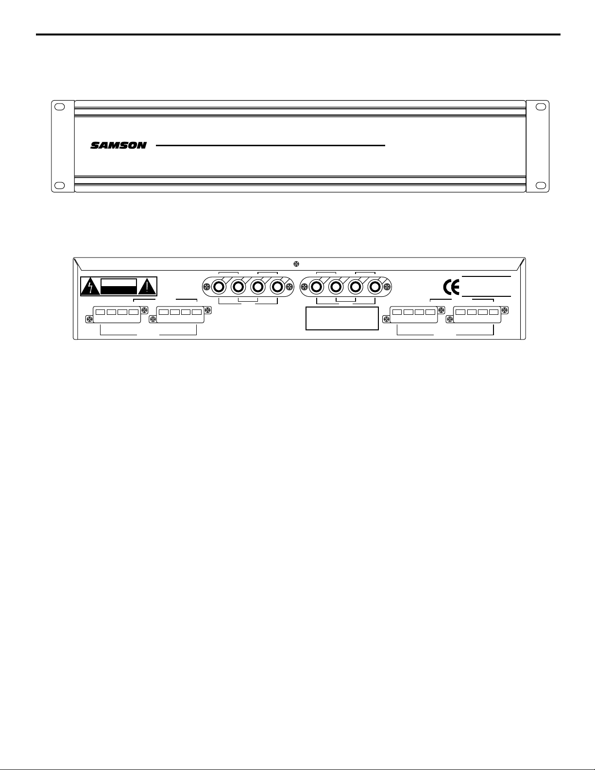
Guided Tour
1: Channel inputs (1 - 4) - Connect output signal from a power amplifier to these four
sets of binding post input connectors, making sure to follow the polarity markings
silk-screened above each connector. When using the DS70 in two-zone (bridged)
modes of operation, a bridge connection must be physically made between two channel
inputs as silk-screened on the rear panel (i.e., between the negative terminal of the oddnumbered channel and the positive terminal of the even-numbered channel). See the
wiring diagrams on pages 6 and 7 in this manual for more information.
2: Channel outputs (1 - 4) - These four sets of screw terminal output connectors are
used to send signal from the DS70 to speaker transformers and loudspeakers. When
using the DS70 in two-zone (bridged) modes of operation, a bridge connection must be
physically made between two channel ouputs as silk-screened on the rear panel. See
the wiring diagrams on pages 6 and 7 in this manual for more information.
4
4 X 120W
TT 70
T SPEAKER DISTRIB
UTION SYSTEM
4 X 120W
ATT 70
VOLOLT SPEAKER DISTRIB
UTION SYSTEM
DS70
CAUTION
RISK OF ELECTRIC SHOCK
DO NOT OPEN
COMCOM25.2V70V
CH1 OUTPUT
BRIDGE 100V
INPUT
+
–
CH3 CH4
BRIDGE
–
+
COMCOM25.2V70V
CH3 OUTPUT
BRIDGE 100V
AVIS
RISQUE DE CHOC ELECTRONIQUE
NE PAS OUVRIR
DO NOT EXPOSE THIS EQUIPMENT
TO RAIN OR MOISTURE
BRIDGE 70V
NC100V
140V
CH4 OUTPUT
COMCOM25.2V70V
DS70
SPEAKER DISTRIBUTION
BRIDGE 70V
70V
NC100V
140V
CH2 OUTPUT
+
–
COMCOM25.2V
CH1 CH2
SAMSON
SAMSON TECHNOLOGIES CORP.
SPEAKER DISTRIBUTION SYSTEM
INPUT
BRIDGE
–
+
SERIAL NUMBER
Page 5

About Distributed Sound
A distributed sound system (sometimes known as a “constant voltage” system) allows a
single power amplifier to drive multiple loudspeakers over a single high-impedance line.
Used commonly in public address and paging systems (such as in schools, houses of
worship, hotels, factories, stores, and other places of business), distributed sound offers
numerous advantages:
• All wiring is in parallel and is therefore simple and straightforward.
• Even if a speaker fails, all other speakers in the system continue operating normally.
• Speakers can be freely added to or removed from the system without affecting the
levels of existing speakers in the system.
• As many speakers as are necessary can be used, as long as their total wattage
requirement does not exceed the power capacity of the power amplifier or DS70.
• Long runs of inexpensive, thin-gauge cable can be used with minimal signal loss.
• The use of tapped speaker transformers (as shown below) enables different power
levels to be selected for each individual speaker, thus providing volume control over
different areas.
However, because such a system relies greatly on the quality of the speaker
transformers, there is a trade-off in terms of reduced low-frequency response. For this
reason, many quality power amplifiers cannot be used in distributed sound systems since
they provide only low-impedance outputs (typically 8 ohms) in order to deliver full
bandwidth to connected speakers. The Samson DS70 is designed to bridge that gap.
By providing toroidal step-up transformers that deliver an output voltage that remains
constant regardless of load impedance, it allows the finest power amplifiers to be
integrated into distributed sound systems. When used in conjunction with quality
speaker transformers, the end result is extraordinary audio fidelity.
The most common voltages used by distributed sound systems in the U.S. are 70, 100,
and 25.2 (wiring code in the U.S. allows 25.2 volt cabling to be used without conduits),
and the DS70 supports all three standards. What’s more, up to four separate lines can
be output simultaneously (making for four “zones”)—and they can even be at different
voltages. In addition, the DS70 provides a 140 volt output (for use in custom-designed
systems where extremely long cable runs are necessary) as well as unique two-zone
“Bridged 70 Volt” and “Dual 70 Volt” modes, where two channels output the same input
signal. This not only allows the level of each zone to be controlled independently, it also
ensures that a line failure in one zone does not affect the other one. Wiring diagrams for
all modes of operation are provided on the following pages.
5
High-impedance line
Speaker
transformers
(labeled in
watts per 70V)
4.0
-
+
0.5
1.0
2.0
4.0
-
+
0.5
1.0
2.0
4.0
-
+
0.5
1.0
2.0
0.5
1.0
2.0
4.0
-
+
Page 6

6
Four-Zone 70V (Unbridged) Wiring
The illustration below shows the wiring for a single channel of a DS70 being used in standard 70 volt mode. In this kind
of setup, the output level controls of the power amplifier can be used to control the volumes of each of the four zones.
For volume control of each of the speakers within a zone, an optional autotransformer can be used (see Appendix A on
page 9 of this manual for more information). Note that four speakers are being used for purposes of illustration only—any
number of speakers (up to the rated wattage of the power amplifier or DS70) can in fact be used in each zone. Note also
that the the remaining three channels of the DS70 can be used to provide the same or different output voltages.
+
-
+
-
+
-
+
-
CAUTION
RISK OF ELECTRIC SHOCK
DO NOT OPEN
COMCOM25.2V70V
CH1 OUTPUT
CAUTION
RISK OF ELECTRIC SHOCK
DO NOT OPEN
USE CLASS 2 WIRING
emc
EUR . USA . JPN
AVIS;
RISQUE DE CHOC ELECTRIQUE
NE PAS OUVRIR
DO NOT EXPOSE THIS EQUIPMENT
TO RAIN OR MOISTURE.
BRIDGE 100V
!
DS70
SPEAKER DISTRIBUTION
BRIDGE 70V
70V
NC100V
140V
CH2 OUTPUT
-++-
-+
CH4
BRIDGE
OFF ON
CH4 R
+
–
COMCOM25.2V
CH1 CH2
SAMSON
SAMSON TECHNOLOGIES CORP.
SPEAKER DISTRIBUTION SYSTEM
+-
4Ω 120W
CH3
MAX. LOAD
+
MONO 8Ω
CH3 R
INPUT
BRIDGE
+
AC
INLET
CAUTION:
DISCONNECT SUPPLY CORD
BEFORE CHANGING FUSE.
FOR CONTINUED PROTECTION
AGAINST RISK OF FIRE, REPLACE
ONLY WITH SAME TYPE OF FUSE.
FUSE
–
USA & CANADA 115V - 60Hz
EUROPE & UK 230V - 50Hz
650W MAX.
USA & CANADA
T 8A/125V (115V)
EUROPE AND UK
T 6.3A/250V (230V)
+
CH3 CH4
SERIAL NUMBER
ATTENTION:
DEBRANCHER AVANT DE
REMPLACER LE FUSIBLE.
UTILISERUN FUSIBLE DE
RECHANGE DE MEM TYPE.
INPUT
–
BRIDGE
–
+
-++-
-+
CH2
+
CH2 L
4Ω 120W
MAX. LOAD
MONO 8Ω
CH3 OUTPUT
+-
CH1
-
CH1 L
AVIS
RISQUE DE CHOC ELECTRONIQUE
NE PAS OUVRIR
DO NOT EXPOSE THIS EQUIPMENT
TO RAIN OR MOISTURE
BRIDGE 70V
COMCOM25.2V70V
NC100V
140V
BRIDGE 100V
SERVO 4120
SERIAL NUMBER
SAMSON
SAMSON TECHNOLOGIES CORP., U.S.A.
BRIDGE
OFF ON
CH4 OUTPUT
QUAD AMPLIFIER
COMCOM25.2V70V
Page 7

7
The illustration below shows the wiring for two channels of a DS70 being used in Bridged 70 volt mode. Since the two
input channels are bridged, a signal of up to 240 watts (into 8 ohms) can be received from the power amplifier. In this
kind of setup, the output level controls of the power amplifier can be used to control the volumes of each of the two zones.
For volume control of each of the speakers within a zone, an optional autotransformer can be used (see Appendix A on
page 9 of this manual for more information). Note that four speakers per channel are being used for purposes of
illustration only—any number of speakers (up to the rated wattage of the power amplifier or DS70) can in fact be used in
each zone. Note also that the the remaining two channels of the DS70 can be used to provide the same or different
output voltages.
CAUTION
RISK OF ELECTRIC SHOCK
DO NOT OPEN
!
USE CLASS 2 WIRING
AVIS;
RISQUE DE CHOC ELECTRIQUE
NE PAS OUVRIR
DO NOT EXPOSE THIS EQUIPMENT
TO RAIN OR MOISTURE.
emc
EUR . USA . JPN
BRIDGE
OFF ON
CH4 R
CH3 R
CH4
CH3
4Ω 120W
MAX. LOAD
-++-
CH2 L
CH1 L
-++-
BRIDGE
OFF ON
SAMSON
SERIAL NUMBER
SERVO 4120
QUAD AMPLIFIER
SAMSON TECHNOLOGIES CORP., U.S.A.
AC
INLET
USA & CANADA 115V - 60Hz
EUROPE & UK 230V - 50Hz
650W MAX.
CAUTION:
DISCONNECT SUPPLY CORD
BEFORE CHANGING FUSE.
FOR CONTINUED PROTECTION
AGAINST RISK OF FIRE, REPLACE
ONLY WITH SAME TYPE OF FUSE.
ATTENTION:
DEBRANCHER AVANT DE
REMPLACER LE FUSIBLE.
UTILISERUN FUSIBLE DE
RECHANGE DE MEM TYPE.
USA & CANADA
T 8A/125V (115V)
EUROPE AND UK
T 6.3A/250V (230V)
FUSE
-+
+-
MONO 8Ω
-
+
CH2
CH1
4Ω 120W
MAX. LOAD
-+
+-
MONO 8Ω
-
+
COMCOM25.2V70V
CH1 OUTPUT
COMCOM25.2V
NC100V
70V
140V
CH2 OUTPUT
SAMSON
SAMSON TECHNOLOGIES CORP.
SPEAKER DISTRIBUTION SYSTEM
INPUT
+
–
–
+
CH3 CH4
INPUT
+
–
–
+
CH1 CH2
BRIDGE
BRIDGE
BRIDGE 70V
COMCOM25.2V70V
RISK OF ELECTRIC SHOCK
DO NOT OPEN
CAUTION
AVIS
RISQUE DE CHOC ELECTRONIQUE
NE PAS OUVRIR
DO NOT EXPOSE THIS EQUIPMENT
TO RAIN OR MOISTURE
SERIAL NUMBER
DS70
SPEAKER DISTRIBUTION
BRIDGE 100V
CH3 OUTPUT
NC100V
140V
CH4 OUTPUT
BRIDGE 100V
COMCOM25.2V70V
BRIDGE 70V
+
-
+
-
+
-
+
-
+
-
+
-
+
-
+
-
Two-Zone 70V (Bridged) Wiring
Page 8

8
The illustration below shows the wiring for a single channel of a DS70 being used in 25.2 volt mode. In this kind of setup,
the output level controls of the power amplifier can be used to control the volumes of each of the four zones. For volume
control of each of the speakers within a zone, optional autotransformers can be used (see Appendix A on page 9 of this
manual for more information). Note that four speakers are being used for purposes of illustration only—any number of
speakers (up to the rated wattage of the power amplifier or DS70) can in fact be used in each zone. Note also that the
the remaining three channels of the DS70 can be used to provide the same or different output voltages.
Four-Zone 25.2V (Unbridged) Wiring
+
-
+
-
+
-
+
-
CAUTION
RISK OF ELECTRIC SHOCK
DO NOT OPEN
COMCOM25.2V70V
CH1 OUTPUT
CAUTION
RISK OF ELECTRIC SHOCK
DO NOT OPEN
USE CLASS 2 WIRING
emc
EUR . USA . JPN
AVIS;
RISQUE DE CHOC ELECTRIQUE
NE PAS OUVRIR
DO NOT EXPOSE THIS EQUIPMENT
TO RAIN OR MOISTURE.
BRIDGE 100V
!
DS70
SPEAKER DISTRIBUTION
BRIDGE 70V
70V
NC100V
140V
CH2 OUTPUT
-++-
-+
CH4
BRIDGE
OFF ON
CH4 R
+
–
COMCOM25.2V
CH1 CH2
SAMSON
SAMSON TECHNOLOGIES CORP.
SPEAKER DISTRIBUTION SYSTEM
+-
4Ω 120W
CH3
MAX. LOAD
+
MONO 8Ω
CH3 R
INPUT
BRIDGE
+
AC
INLET
CAUTION:
DISCONNECT SUPPLY CORD
BEFORE CHANGING FUSE.
FOR CONTINUED PROTECTION
AGAINST RISK OF FIRE, REPLACE
ONLY WITH SAME TYPE OF FUSE.
FUSE
–
USA & CANADA 115V - 60Hz
EUROPE & UK 230V - 50Hz
650W MAX.
USA & CANADA
T 8A/125V (115V)
EUROPE AND UK
T 6.3A/250V (230V)
+
CH3 CH4
SERIAL NUMBER
ATTENTION:
DEBRANCHER AVANT DE
REMPLACER LE FUSIBLE.
UTILISERUN FUSIBLE DE
RECHANGE DE MEM TYPE.
INPUT
–
BRIDGE
–
+
-++-
-+
CH2
+
CH2 L
4Ω 120W
MAX. LOAD
MONO 8Ω
CH3 OUTPUT
+-
CH1
-
CH1 L
AVIS
RISQUE DE CHOC ELECTRONIQUE
NE PAS OUVRIR
DO NOT EXPOSE THIS EQUIPMENT
TO RAIN OR MOISTURE
BRIDGE 70V
COMCOM25.2V70V
NC100V
140V
BRIDGE 100V
SERVO 4120
SERIAL NUMBER
SAMSON
SAMSON TECHNOLOGIES CORP., U.S.A.
BRIDGE
OFF ON
CH4 OUTPUT
QUAD AMPLIFIER
COMCOM25.2V70V
Page 9

Two-Zone 100V (Bridged) Wiring
The illustration below shows the wiring for a single channel of a DS70 being used in 100 volt mode. Because each
transformer within the DS70 can deliver up to 70 volts, so to get a 100 volt output, two of the transformers have to be
bridged (i.e., connected in series). Since the two input channels are bridged, a signal of up to 240 watts (into 8 ohms)
can be received from the power amplifier. In this kind of setup, the output level controls of the power amplifier can be
used to control the volumes of each of the two zones. For volume control of each of the speakers within a zone, optional
autotransformers can be used (see Appendix A on page 9 of this manual for more information). Note that four speakers
are being used for purposes of illustration only—any number of speakers (up to the rated wattage of the power amplifier
or DS70) can in fact be used in each zone. Note also that the the remaining two channels of the DS70 can be used to
provide the same or different output voltages.
9
+
-
+
-
+
-
+
-
CAUTION
RISK OF ELECTRIC SHOCK
DO NOT OPEN
COMCOM25.2V70V
CH1 OUTPUT
CAUTION
RISK OF ELECTRIC SHOCK
DO NOT OPEN
USE CLASS 2 WIRING
emc
EUR . USA . JPN
AVIS;
RISQUE DE CHOC ELECTRIQUE
NE PAS OUVRIR
DO NOT EXPOSE THIS EQUIPMENT
TO RAIN OR MOISTURE.
BRIDGE 100V
!
DS70
SPEAKER DISTRIBUTION
BRIDGE 70V
70V
140V
CH2 OUTPUT
-++-
-+
BRIDGE
OFF ON
INPUT
+
–
CH1 CH2
COMCOM25.2V
NC100V
4Ω 120W
CH4
MAX. LOAD
MONO 8Ω
CH4 R
BRIDGE
SAMSON
SAMSON TECHNOLOGIES CORP.
SPEAKER DISTRIBUTION SYSTEM
+-
CH3
+
CH3 R
+
AC
INLET
CAUTION:
DISCONNECT SUPPLY CORD
BEFORE CHANGING FUSE.
FOR CONTINUED PROTECTION
AGAINST RISK OF FIRE, REPLACE
ONLY WITH SAME TYPE OF FUSE.
FUSE
–
USA & CANADA 115V - 60Hz
EUROPE & UK 230V - 50Hz
650W MAX.
USA & CANADA
T 8A/125V (115V)
EUROPE AND UK
T 6.3A/250V (230V)
SERIAL NUMBER
ATTENTION:
DEBRANCHER AVANT DE
REMPLACER LE FUSIBLE.
UTILISERUN FUSIBLE DE
RECHANGE DE MEM TYPE.
INPUT
+
–
CH3 CH4
BRIDGE
–
+
CH3 OUTPUT
-++-
MAX. LOAD
+
4Ω 120W
MONO 8Ω
+-
CH1
-
CH1 L
-+
CH2
CH2 L
AVIS
RISQUE DE CHOC ELECTRONIQUE
NE PAS OUVRIR
DO NOT EXPOSE THIS EQUIPMENT
TO RAIN OR MOISTURE
BRIDGE 70V
COMCOM25.2V70V
140V
BRIDGE 100V
SERVO 4120
QUAD AMPLIFIER
SERIAL NUMBER
SAMSON
SAMSON TECHNOLOGIES CORP., U.S.A.
BRIDGE
OFF ON
CH4 OUTPUT
COMCOM25.2V70V
NC100V
Page 10

Two-Zone 140V (Bridged) Wiring
10
The illustration below shows the wiring for a single channel of a DS70 being used in a non-standard 140 volt mode
(which can be used with custom equipment where exceptionally long cable runs are required. Because each transformer
within the DS70 can deliver up to 70 volts, so to get a 140 volt output, two of the transformers have to be bridged
(i.e., connected in series). Since the two input channels are bridged, a signal of up to 240 watts (into 8 ohms) can be
received from the power amplifier. In this kind of setup, the output level controls of the power amplifier can be used to
control the volumes of each of the two zones. For volume control of each of the speakers within a zone, optional
autotransformers can be used (see Appendix A on page 9 of this manual for more information). Note that four speakers
are being used for purposes of illustration only—any number of speakers (up to the rated wattage of the power amplifier
or DS70) can in fact be used in each zone. Note also that the the remaining two channels of the DS70 can be used to
provide the same or different output voltages.
+
-
+
-
+
-
+
-
CAUTION
RISK OF ELECTRIC SHOCK
DO NOT OPEN
COMCOM25.2V70V
CH1 OUTPUT
CAUTION
RISK OF ELECTRIC SHOCK
DO NOT OPEN
USE CLASS 2 WIRING
emc
EUR . USA . JPN
AVIS;
RISQUE DE CHOC ELECTRIQUE
NE PAS OUVRIR
DO NOT EXPOSE THIS EQUIPMENT
TO RAIN OR MOISTURE.
BRIDGE 100V
!
DS70
SPEAKER DISTRIBUTION
BRIDGE 70V
70V
NC100V
140V
CH2 OUTPUT
-++-
-+
CH4
BRIDGE
OFF ON
CH4 R
+
–
COMCOM25.2V
CH1 CH2
SAMSON
SAMSON TECHNOLOGIES CORP.
SPEAKER DISTRIBUTION SYSTEM
+-
4Ω 120W
CH3
MAX. LOAD
+
MONO 8Ω
CH3 R
INPUT
BRIDGE
+
AC
INLET
CAUTION:
DISCONNECT SUPPLY CORD
BEFORE CHANGING FUSE.
FOR CONTINUED PROTECTION
AGAINST RISK OF FIRE, REPLACE
ONLY WITH SAME TYPE OF FUSE.
FUSE
–
USA & CANADA 115V - 60Hz
EUROPE & UK 230V - 50Hz
650W MAX.
USA & CANADA
T 8A/125V (115V)
EUROPE AND UK
T 6.3A/250V (230V)
+
CH3 CH4
SERIAL NUMBER
ATTENTION:
DEBRANCHER AVANT DE
REMPLACER LE FUSIBLE.
UTILISERUN FUSIBLE DE
RECHANGE DE MEM TYPE.
INPUT
–
BRIDGE
–
+
-++-
-+
CH2
+
CH2 L
4Ω 120W
MAX. LOAD
MONO 8Ω
CH3 OUTPUT
+-
CH1
-
CH1 L
AVIS
RISQUE DE CHOC ELECTRONIQUE
NE PAS OUVRIR
DO NOT EXPOSE THIS EQUIPMENT
TO RAIN OR MOISTURE
BRIDGE 70V
COMCOM25.2V70V
140V
BRIDGE 100V
SERVO 4120
QUAD AMPLIFIER
SERIAL NUMBER
SAMSON
SAMSON TECHNOLOGIES CORP., U.S.A.
BRIDGE
OFF ON
CH4 OUTPUT
COMCOM25.2V70V
NC100V
Page 11

11
Note: The block diagram below shows the signal flow for a single channel of the DS70.
Appendix A: Block Diagram
Power
amplifier
DS70
Optional
local switcher
and volume control
Speaker
transformer
Page 12

12
Specifications
1: Input Impedance 4 Ω (non-bridged modes)
8 Ω (bridged modes)
2 Ω (dual mode)
2: Maximum Power Each Input 120 Wrms (non-bridged modes)
240 Wrms (bridged and dual modes)
3: Output 70 V, 25.2 V (non-bridged),
100 V, 140 V (bridged)
4: Insertion Loss -0.55 dB @ 1kHz
5: Frequency Response Flat, +0 dB, -3 dB 20 Hz to 20 kHz, ref. 1 kHz
-1 dB, 15 Hz & 9.1 kHz @ 120 Wrms
-3 dB, 10 Hz & 20 kHz @ 120 Wrms
6: THD + N < .04% @ 120 Wrms
7: Dimensions 482 mm (w) x 190 (d) x 88 (h)
19 in. (w) x 7.5 (d) x 3.5 (h)
8: Weight 35 lb. • 18.88 kg
DS70 Modes of Operation:
+ –
70V 25.2V COM COM
+ –
UNBRIDGED 70V
TO 4Ω
+ –
+ –
70V 25.2V COMCOM
+ –
UNBRIDGED 25.2V
TO 4Ω
+ –
+ –
140V 100V COM COM
+
+ –
BRIDGED 100V
TO 8Ω
70V 25.2V
+ –
COM COM
–
COM70V 25.2V COM COM
+
BRIDGED 70V
25.2V
70V COM
–
TO 8Ω
+
COM70V 25.2V COM COM
DUAL 70V
TO PARALLEL 2Ω
25.2V
70V COM
–
+
–
Page 13

Produced by On The Right Wavelength for Samson Technologies Corp.
Copyright 1998, Samson Technologies Corp.
Printed January 1998
Samson Technologies Corp.
575 Underhill Blvd.
P.O. Box 9031
Syosset, NY 11791-9031
Phone: 1-800-3-SAMSON (1-800-372-6766)
Fax: 516-364-3888
 Loading...