

Samson CT7, UM1, HT7 Owner's Manual

samsontech.com
MICRO DIVERSITY WIRELESS SYSTEM FOR VIDEO
Owners Manual

Copyright 2005 - 2007, Samson Technologies Corp.
Printed May, 2007 v1.1
Samson Technologies Corp.
45 Gilpin Avenue
Hauppauge, New York 11788-8816
Phone: 1-800-3-SAMSON (1-800-372-6766)
Fax: 631-784-2201
www.samsontech.com

ENGLISH
Introduction / System Features .................. 2
System Features . . . . . . . . . . . . . . . . . . . . . . . . . . . . 2
Guided Tour - UM1 .......................... 4
Guided Tour - CT7 . . . . . . . . . . . . . . . . . . . . . . . . . . . 6
Guided Tour - HT7 . . . . . . . . . . . . . . . . . . . . . . . . . . . 8
Setting Up and Using Your UM1 System . . . . . . . . . . . . . 9
FRANÇAIS
Introduction / Caractéristiques du systèmes . . . . . . . . . .12
Caractéristiques du système . . . . . . . . . . . . . . . . . . . .12
Visite guidée - UM1 . . . . . . . . . . . . . . . . . . . . . . . . . .14
Visite guidée - UM1 . . . . . . . . . . . . . . . . . . . . . . . . . .15
Visite guidée - CT7 ..........................16
Visite guidée - HT7 . . . . . . . . . . . . . . . . . . . . . . . . . . 18
Paramétrage et utilisation du système UM1 . . ........19
DEUTSCHE
Einleitung / System-Merkmales . . . . . . . . . . . . . . . . . .22
System-Merkmale . . . . . . . . . . . . . . . . . . . . . . . . . . .22
Bedienelemente - UM1 .......................24
Bedienelemente - CT7 . . . . . . . . . . . . . . . . . . . . . . . .26
Bedienelemente - HT7 . . . . . . . . . . . . . . . . . . . . . . . .28
Aufbau und Betrieb des UM1 ...................29
ESPAÑOL
Introducción / Características del sistemas . . . . . . . . . . .32
Características del sistema .....................33
Recorrido guiado: UM1 .......................34
Recorrido guiado - CT7 .......................36
Recorrido guiado - HT7 .......................38
Ajuste y utilización de su sistema UM1 .............39
Appendix A: CT7 Multipin .....................42
Wiring Guide and Chart . . . . . . . . . . . . . . . . . . . . . . .42
Specifications .............................43

ENGLISH
2
Introduction / System Features
Congratulations on purchasing the Samson UM1 micro diversity receiver—part of our renowned
UHF Series One Wireless System! Although this product is designed for easy operation, we suggest you first take some time to go through these pages so you can fully understand how we’ve
implemented a number of unique features.
Every wireless system consists of at least two components—a transmitter and a receiver, both of
which must be tuned to the same channel (that is, the same radio frequency) in order to operate
correctly.* The Samson UM1 system you have purchased operates in the 801 - 805 MHz frequency
range and contains a UM1 micro diversity receiver and one of three Concert 77 transmitters: a
CT7(L) belt-pack transmitter (for lavalier microphone or headset applications); a CT7(G) belt-pack
transmitter (for instrument applications); or a HT7 hand-held microphone transmitter (available in
a wide variety of popular capsules).
The UM1 system is specially designed to enable the production of professional audio tracks to
accompany your video shoot or live broadcast. The use of a handheld mic transmitter or lavalier
microphone connected to a beltpack transmitter effectively isolates the performer from unwanted ambient sounds such as video camera motor noise or room sounds made by the camera
operator or video crew. Because the UM1 receiver is extremely small and lightweight, it can be
attached easily to any video camera using the supplied strip of velcro, and can even be powered
directly by the camera’s own 12-volt power supply, if available.
In this manual, you’ll find a more detailed description of the features of the UM1 system, as well as
a guided tour through all components, step-by-step instructions for setting up your system, wiring diagrams and tables, and full specifications. If your UM1 system was purchased in the United
States, you’ll also find a warranty card enclosed—don’t forget to fill it out and mail it! This will
enable you to receive online technical support and will allow us to send you updated information
about this and other Samson products in the future. If your UM1 system was purchased outside of
the U. S., contact your local distributor for warranty details.
SPECIAL NOTE for U.S. purchasers: Should your UM1 system ever require servicing, a Return
Authorization number (RA) is necessary. Without this number, the unit will not be accepted. If
your UM1 system was purchased in the United States, please call Samson at 1-800-372-6766 for a
Return Authorization number prior to shipping your unit. If possible, return the unit in its original
carton and packing materials. If your UM1 system was purchased outside of the U. S., contact your
local distributor for servicing information.
* Your receiver and transmitter have been factory preset to utilize the same channel. A listing of the six
available channels and their corresponding UHF frequencies can be found on page 4 of this manual.
System Features
Designed for use in both live sound and sound contracting applications, the Samson UM1 system
provides a high performance, cost effective solution, utilizing state-of-the-art technology in wireless communications. Main features include:
• Six different available channels, all operating in the less crowded UHF bandwidth, and all
designed for simultaneous use. This means that you can use multiple UM1 systems (each tuned
to a different channel) in the same location without interference.
642-646

ENGLISH
3
System Features
• Optimized for use in videography applications, the UM1 system is highly customizable, combining a UHF “walkaround” receiver with your choice of Samson Concert 77 beltpack or handheld microphone transmitters.
• Using the supplied velcro strip, the compact, lightweight UM1 receiver can be easily attached
to any video camera and can even derive 12 volt power from the camera (if available), making it
easy to integrate into any traveling or fixed installation video system.
• The UM1 micro diversity receiver includes a pair of tuned antennas and provides both balanced
and unbalanced outputs (with a three-position output level switch) and a headphone monitor
output with continuously adjustable level control. The receiver also includes an audio peak
LED, dual receiver indicators, and an RF strength meter.
• All components use standard 9-volt batteries, with battery life of more than 12 hours,* and
feature a convenient three-segment multicolor Battery Strength LED meter (which in the UM1
can also be used as an RF level meter), allowing you to monitor the remaining power in the
installed battery.
• True Diversity technology maximizes active range (up to 300 feet) and reduces potential interference problems through automatic switching between two independent receivers.
• Built-in companding noise reduction in all components for crystal-clear sound with minimized
background noise and hiss.
• Transmitters provide “popless” muting, which turns off the audio signal while leaving the carrier
signal on.
• Incredibly compact CT7 belt-pack transmitters are extremely lightweight (less than 4 ounces
with a 9-volt battery installed). The CT7 provides a Switchcraft TB3M mini-XLR jack for connection to a variety of popular headsets and lavalier microphones, including:
Samson QE headset**
Samson QV headset
Samson QV10e headset
Samson HS5P3 headset
Samson HM40P Wind Instrument Mic
Samson LM5P3 lavalier
Samson QL5 lavalier
Audio-Technica MT-350 lavalier
Audio-Technica AT -831 lavalier
Applied Microphone Technology Roaming One wind instrument microphone
Sony ECM-44 lavalier
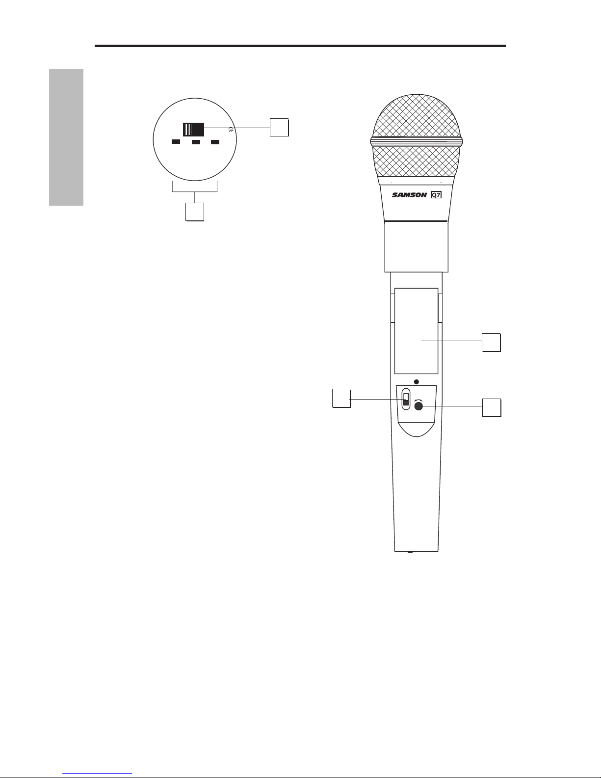
• The HT7 hand-held microphone transmitter is available with either the Samson Q7
Neodymium dynamic microphone capsule, or the Samson C05 Condenser microphone capsule.
* Typical usage. Actual battery life in the UM1 may vary depending upon headphone and metering
usage and headphone output level.
ENGLISH
4
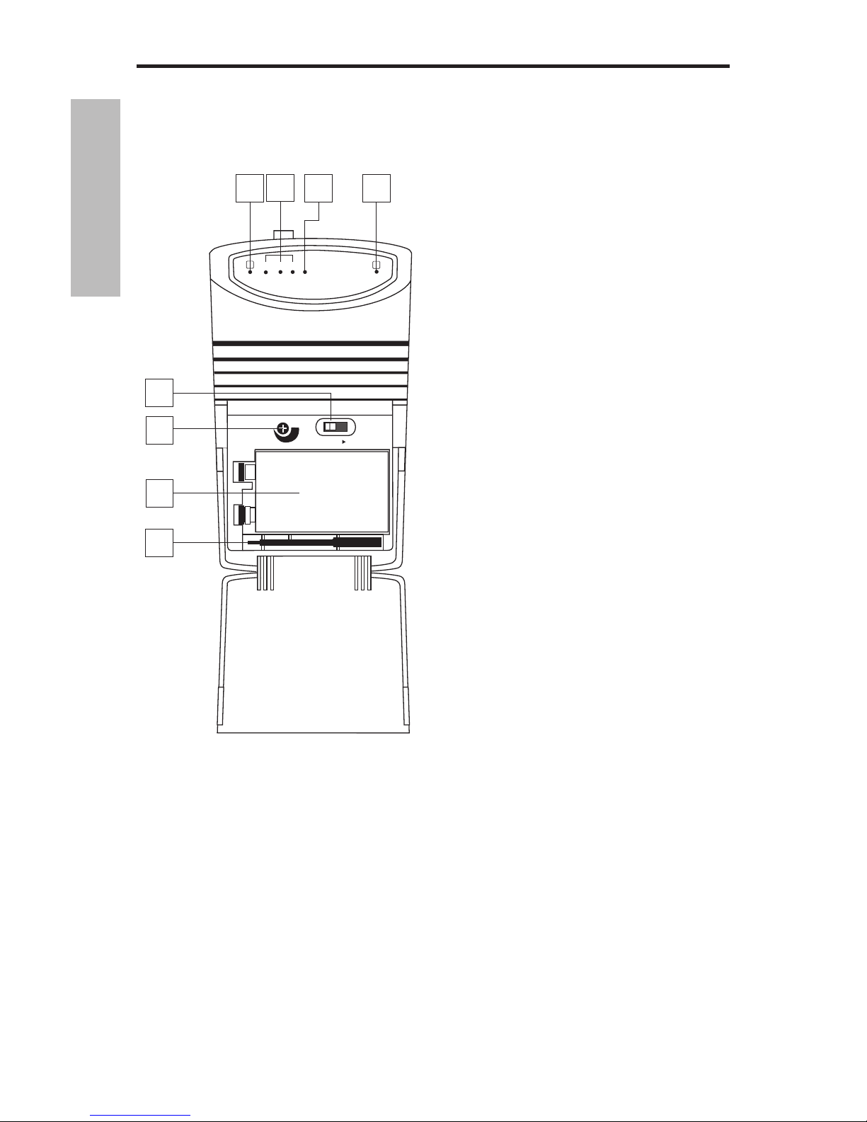
1: A/B Receiver LEDs - When signal is being
received, one of these will be lit orange, showing
you whether the (left)“A” or (right) “B” receiver
is currently being used. The UM1 constantly
scans its two antennas and automatically selects
whichever is receiving the strongest, clearest
signal. This True Diversity switching is complete-
ly inaudible, but it effectively increases overall
range while virtually eliminating potential interference and phase cancellation problems.
2: Meter - This set of three multicolor LEDs acts
as a meter, indicating either battery power or
the strength of the incoming RF signal. This
meter can also be disabled altogether to conserve battery power. See #15 on the next page
for more information.
3: Peak LED - This LED lights red when output
signal from the UM1 is at the onset of clipping
(that is, when it is on the verge of being distorted). If you see this light during operation,
move the microphone further away or lower the
output level of your instrument or transmitter.
For more information, see the section entitled
“Setting Up and Using the UM1 System” on page
9 in this manual.
4: Power switch - Use this to turn the UM1
power on and off.
5: SQ (Squelch) Level control - This control
determines the maximum range of the UM1
before audio signal dropout. Although it can be
adjusted using the supplied plastic screwdriver,
it should normally be left at its factory setting.
See the “Setting Up and Using the UM1 System”
section on page 9 in this manual for more information.
6: Battery holder - Insert a standard 9-volt alka-
line battery here, being sure to observe the plus and minus polarity markings shown. We recommend the Duracell MN 1604 type battery. Although rechargeable Ni-Cad batteries can be used,
they do not supply adequate current for more than four hours. WARNING: Do not insert the bat-
tery backwards; doing so can cause severe damage to the UM1 and will void your warranty.
7: Plastic screwdriver - Specially designed for use in adjusting the UM1 Squelch Level control
(see #4 above). See the “Setting Up and Using the UM1 System” section on page 9 in this manual
for more information.
8: Antennas (A and B) - The antenna mountings allow full rotation for optimum placement. In
normal operation, both antennas should be placed in a vertical position. Both antennas can be
folded inward for convenience when transporting the UM1. See the “Setting Up and Using the
UM1” section on page 9 in this manual for more information.
Guided Tour - UM1
SAMSON
SAMSON
MAX
MIN
POWER
ON
SQ LEVEL
UHF MICRO DIVERSITY RECEIVER
B
A
LOW MID HIGH PEAK
800
MHz
2
3
1
5
7
4
6
1
+
-
600HMz
5
ENGLISH
6
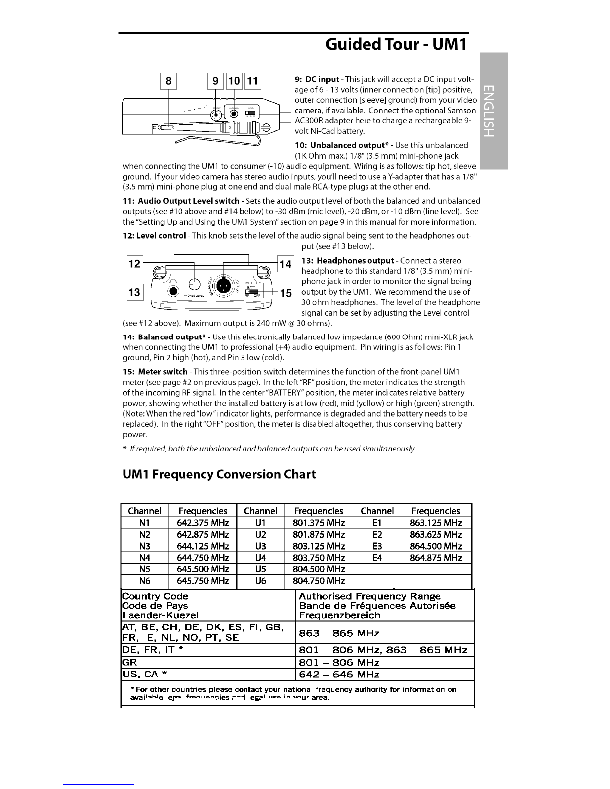
1: Input connector - The input device is connected here. The CT7 is supplied with either a lavalier or headset microphone or 1/4" jack cable (connected via a mini-XLR jack).
2: Power / Battery LED - This LED flashes once when the CT7 is first turned on and lights steadily
red when there are less than 2 hours of battery power remaining, indicating that the battery
needs to be changed. In order to avoid compromising audio fidelity (or having the CT7 stop
working completely), you should always replace the battery with a fresh one immediately whenever this LED lights red.
3: Audio on-off switch - When set to the “on” position, audio signal is transmitted. When set
to the “off” position, the audio signal is muted. Because the carrier signal remains during muting, no “pop” or “thud” will be heard. Note that turning this off does not turn off the transmitter
power—it is simply a way to temporarily mute the transmission of audio signal. If you don’t plan
on using the transmitter for extended periods, turn off the transmitter power by using the power
on-off switch (see #8 on the next page).
4: Belt clip - Use this clip to fasten the CT7 to a belt.
5: Battery cover release - Push in both sides of the battery
cover and pull back to open the CT7 battery cover.
6: Antenna - This permanently attached transmitter
“stiff” antenna should be fully extended for normal operations. See the “Setting Up and Using the Concert Series
System” section on page 9 in this manual for more information about antenna positioning.
Guided Tour - CT7
1
4
2
3
5
5
6
ENGLISH
7
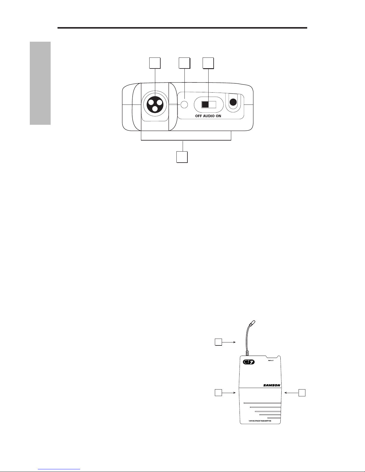
Guided Tour - CT7
11
9
10
7
8
7: Attenuation switch - The CT7 transmitter features a signal Attenuation switch that is used
to select the input level of “0dB” or “-15dB”. This Attenuation switch has been factory preset to
“0dB” providing the optimum level for most microphone and instrument input signals. If you are
using a microphone or instrument with a high output signal, first try to adjust the Gain control as
described in the following section. If you cannot attenuate the signal low enough using the Gain
control, use the supplied plastic screwdriver (see #8 below) to turn the rotary Attenuation switch
to the counter-clockwise position setting the CT7 to “-15dB” level.
8: Audio Input Level control (trimpot) - This input sensitivity control has been factory preset to
provide optimum level for the particular lavalier, headset or for optimum instrument level, so we
recommend that this not be adjusted manually. If necessary, however, you can use the supplied
plastic screwdriver (see #10 below) to raise or lower the CT7 input level. See the “Setting Up and
Using the Concert Series System” section on page 9 in this manual for more information.
9: Battery holder - Insert a standard 9-volt alkaline battery here, being sure to observe the
plus and minus polarity markings shown. We recommend the Duracell MN 1604 type battery.
Although rechargeable Ni-Cad batteries can be used, they do not supply adequate current for
more than four hours. WARNING: Do not insert the battery backwards; doing so can cause
severe damage to the CT7 and will void your warranty.
10: Power on-off switch* - Use this to turn the CT7 on or off (to conserve battery power, be sure
to leave it off when not in use).
11: Plastic screwdriver - Specially designed for use in adjusting the CT7 Audio Input Level
control (see #8 above) and/or CR77 Squelch control (see #7 on page 3). See the “Setting Up and
Using the Concert Series System” section on page 9 in this manual for more information.
* Be sure to mute the audio signal at your external mixer or amplifier before turning transmitter power
on or off, or an audible pop may result.
ENGLISH
8
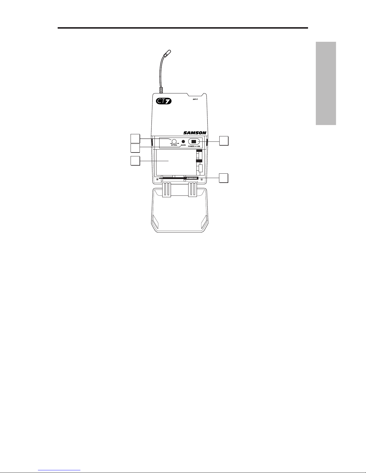
1: Audio on-off switch - When set to the “on” position, audio signal is transmitted. When set to the “off”
position, the audio signal is muted. Because the carrier signal remains during muting, no “pop” or “thud”
will be heard. Note that turning this off does not turn
off the transmitter power—it is simply a way to temporarily mute the transmission of audio signal. If you
don’t plan on using the transmitter for extended periods, turn off the transmitter power by using the power
on-off switch (see #3 below).
2: Battery level meter - This set of three multicolor
LEDs indicates relative battery power, indicating
whether the installed battery is at low (red), mid
(yellow) or high (green) strength. One of these will
light whenever the HT7 is powered on (see #3 below).
When the red “low” indicator lights, RF performance is
degraded and the battery needs to be replaced.
3: Power on-off switch* - Use this to turn the HT7 on
or off (to conserve battery power, be sure to leave it off
when not in use).
4: Microphone Input Level control (trimpot) - This
input sensitivity control has been factory preset to
provide optimum level for the particular microphone
capsule provided with your Concert 77 system and so
we recommend that this not be adjusted manually. If
necessary, however, you can use the supplied plastic screwdriver to raise or lower the input level.
See the “Setting Up and Using the Concert Series System” section on page 9 in this manual for
more information.
5: Battery holder - Insert a standard 9-volt alkaline battery here, being sure to observe the
plus and minus polarity markings shown. We recommend the Duracell MN 1604 type battery.
Although rechargeable Ni-Cad batteries can be used, they do not supply adequate current for
more than four hours. WARNING: Do not insert the battery backwards; doing so can cause
severe damage to the HT7 and will void your warranty.
* Be sure to mute the audio signal at your external mixer or amplifier before turning transmitter power
on or off, or an audible pop may result.
8
Guided Tour - HT7
MIN
MAX
LEVEL
POWER
ON
OFF
5
3
4
1
!5$)/
,/7 -)$ ()'(
"!44%29,%6%,
5
/&& /.
2
&
#
#
)
$
#
#
2
(
4

ENGLISH
9
9
Setting Up and Using Your UM1 System
The basic procedure for setting up and using your UM1 Wireless System takes only a few minutes:
1. For the UM1 system to work correctly, both the receiver and transmitter must be set to the
same channel. Remove all packing materials (save them in case of need for future service) and
check to make sure that the supplied UM1 receiver and CT7 or HT7 transmitter are set to the same
channel. If these channels do not match, contact your distributor or, if purchased in the United
States, Samson Technical Support at 1-800-372-6766.
2a. If you are using a 9-volt battery to power the UM1, press gently down on the battery door
release (on the front of the UM1, on the word “Open”) and swing the door open in order to access
the battery compartment . Note that the door is hinged and is not intended to be removed
from the receiver case. Insert a 9-volt battery, being careful to observe the polarity markings.
Warning: Reversing the battery polarity may cause permanent damage to your receiver.
Turn the power switch “On” and set the Meter switch to “BATTERY.” The green “HIGH” meter LED
will light if the battery is sufficiently strong. Once you’ve verified battery strength, turn the power
switch “Off” again.
2b. If you are using the optional Samson AC300R adapter or your video camera’s 12-volt power
supply to power the UM1, connect it to the UM1 DC input jack. On the front of the UM1, press
gently down on the battery door release (on the word “Open”) and swing the door open note
that the door is hinged and is not intended to be removed from the receiver case). Make sure the
power switch is set to “Off.”
3a. If your system contains a CT7 belt-pack transmitter, push in both sides of the battery cover
and pull back to open the battery door, which is hinged and not intended to be removed from the
transmitter case. Please use care when opening this door as undue force will destroy the hinge.
3b. If your system contains a HT7 handheld transmitter, unscrew the bottom section of the microphone by turning it counterclockwise and then slide it off.
4. Place a fresh 9-volt alkaline battery in the transmitter battery holder, taking care to observe the
polarity markings. If you are using a CT7 belt-pack transmitter, gently replace the battery door by
swinging it up and pressing until it clicks. If you are using a HT7 handheld transmitter, replace the
bottom section of the microphone by sliding it on and then screwing it back on. Whichever transmitter you are using, leave it off for the moment.
5. Next, make the physical cable connection between the output of your UM1 receiver and the
audio input of your video camera or audio amplifier or mixer, being careful to set the Audio
Output Level switch so that the signal is strong but not distorting. Normally, it should be set to
the “-30” position when connecting to a mic-level input and to the “-20” or “-10” position when
connecting to a line-level input. If required, both the balanced and unbalanced outputs can be
used simultaneously. Leave your amplifier (and/or mixer) off at this time.
6. Turn the power to the UM1 “On” and close the battery door.
7. Extend both “A” and “B” antennas from the UM1 and place both in a vertical position.
8. Turn on the power to the CT7 or H7 transmitter; the green “HIGH” Battery strength LED will light
if the battery is sufficiently strong. At this point, either the “A” or “B” orange LED on the front of the
UM1 will light (depending upon which antenna is receiving the stronger signal).
ENGLISH
10
9. Set the UM1 Meter switch to “RF.” One or more segments in the UM1 meter should light. If
the “HIGH” segment lights, the UM1 is receiving an optimally strong RF signal and is placed and
positioned correctly. If the “LOW” segment lights (indicating a relatively weak RF signal), try relocating the UM1 or changing the position of one or both of its antennas.
10. If you want to use headphones to monitor the transmission, connect a standard “Walkman”type 30 ohm headphone to the UM1 headphone output and adjust the Level control until the
desired level is reached.
11. Turn on your connected amplifier and/or mixer but keep its volume all the way down. Next,
make sure that your transmitter is unmuted by setting its Audio switch to “On.” If you are using
the CT7 transmitter or if you are using the CT7 transmitter with a connected lavalier microphone
or headset, speak or sing into the mic at a normal performance level while slowly raising the
volume of your amplifier/mixer until the desired level is reached. If you are using the CT7 transmitter with a connected instrument, play the instrument at normal performance level while
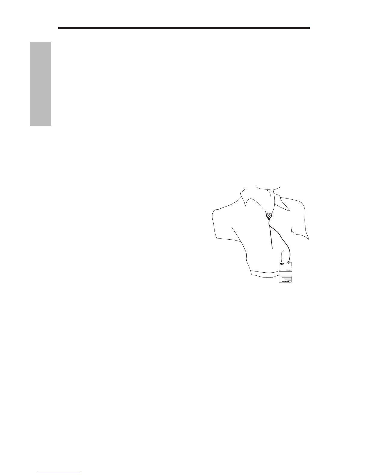
slowly raising the volume of your amplifier/mixer until the desired level is reached. If you are
using a CT7 beltpack transmitter equipped with a lavalier microphone, note that correct lavalier
placement is critical to sound quality. We recommend that you place it as shown in the illustration on the right—as close to your mouth as possible but
off to one side (to minimize nasality) and unobstructed
by clothing. Bear in mind also that omni microphones
(mics which pick up signal from all directions) are more
prone to feedback problems than unidirectional (cardioid
or hypercardioid) ones; in general, you can avoid feedback
by taking care not to use any microphone directly in front
of a PA speaker (if this is unavoidable, try using an equalizer to attenuate those high- or mid-range frequencies
which are causing the feedback “squealing”).
12. If you hear distortion at the desired volume level, first
check to see whether the red “Peak” LED on the UM1 is lit.
If it is not, make sure that the gain structure of your audio
system is correctly set (consult the owners manual of your
mixer and/or amplifier for details). If the red “Peak” LED is
lit, do the following:
• If you are using a HT7 transmitter, use the supplied plastic screwdriver to turn its
Microphone Input Level control (trimpot) slowly counterclockwise (towards the “Min” position) until the distortion disappears.
• If you are using a CT7 transmitter with connected lavalier microphone or headset, its Audio
Input Level control has been factory preset to provide optimum level for the particular
lavalier or headset model being used and so no adjustment should be necessary. Any distortion present should therefore simply be a matter of the microphone being too close to
the mouth; try moving it further away. If this does not solve the problem, use the supplied
plastic screwdriver to turn the Audio Input Level control (trimpot) on the CT7 slowly counterclockwise until the distortion disappears.
• If you are using a CT7 transmitter with an instrument such as electric guitar or bass, lower
the output level of the instrument until the distortion disappears. Alternatively, you can
use the supplied plastic screwdriver to turn the Level control (trimpot) on the CT7 slowly
counterclockwise until the distortion disappears.
10
Setting Up and Using Your UM1 System

ENGLISH
11
11
Setting Up and Using Your UM1 System
13. Conversely, if you hear a weak, noisy signal at the desired volume level, again make sure that
the gain structure of your audio system is correctly set (consult the owners manual of your mixer
and/or amplifier for details). If it is and the signal coming from the UM1 is still weak and/or noisy,
do the following:
• If you are using a HT7 transmitter, use the supplied plastic screwdriver to turn the Level
control (trimpot) on the transmitter slowly clockwise (towards the “Max” position) until the
signal reaches an acceptable level.
• If you are using a CT7 transmitter with connected lavalier microphone or headset, its Level
control has been factory preset to provide optimum level for the particular lavalier or headset model being used and so no adjustment should be necessary. Any weakness of signal
should therefore simply be a matter of the microphone being too far from the mouth; try
moving it closer. If this does not solve the problem, use the supplied plastic screwdriver
to turn the Level control (trimpot) on the CT7 slowly clockwise until the signal reaches an
acceptable level.
• If you are using a CT7 transmitter with an instrument such as electric guitar or bass, raise the
output level of the instrument until a good signal is achieved. Alternatively, you can use the
supplied plastic screwdriver to turn the Level control (trimpot) on the CT7 slowly clockwise
until the signal reaches an acceptable level.
14. Temporarily turn down the level of your mixer/amplifier system and turn off the power to
your transmitter, leaving the UM1 on. Then restore the previously set level of your mixer/amplifier. With the transmitter off, the receiver output should be totally silent—if it is, skip ahead
to the next step. If it isn’t (that is, if you hear some noise), you may need to adjust the UM1 SQ
(squelch) control, located in the battery compartment. When the SQ control is at its minimum
setting, the UM1 system always provides maximum range without dropout; however, depending upon the particular environment your system is used in, you may need to reduce that range
somewhat in order to eliminate band noise when the transmitter is turned off. To do so, use the
provided screwdriver to rotate the SQ control completely counterclockwise (to the “Min” position), then slowly turn it clockwise until the noise disappears. If no noise is present at any position, leave it at its fully counterclockwise “Min” position (so as to have the greatest overall range
available).
15. When first setting up the UM1 system in a new environment, it’s always a good idea to do a
walkaround in order to make sure that coverage is provided for your entire performance area.
Accordingly, turn on both the transmitter and UM1 receiver. If you are using a video camera, use
the supplied velcro strip to attach the UM1 to the side of the camera. If not, physically place the
UM1 in the position in which it will be used. Next, with the transmitter unmuted, walk through
the entire area that will need to be covered while speaking, singing, or playing your instrument.
As you do so, you will find that the orange “A” and “B” LEDs on the UM1 occasionally switch on or
off, always showing you which antenna is receiving the stronger signal. The basic rule of thumb
for all wireless audio systems is to always try to minimize the distance between transmitter and
receiver as much as possible and also to try to maintain “line of sight” between the two (that is,
the person using the transmitter should be able to see the receiver). Always try to minimize the
distance between transmitter and receiver as much as possible so that the strongest possible signal is received from all planned transmission points.
If you have followed all the steps above and are experiencing difficulties, contact your local distributor or, if purchased in the United States, call Samson Technical Support (1-800-372-6766)
between 9 AM and 5 PM EST.

FRANÇAIS
Introduction / Caractéristiques du systèmes
12
Merci d'avoir fait confiance au récepteur micro diversity Samson UM1 — élément de notre célèbre système sans fil UHF Series One ! Veuillez prendre quelques minutes pour lire ces quelques
pages qui vous indiquent comment tirer le meilleur parti des nombreuses caractéristiques de
l'appareil.
vav
Chaque système sans fil est composé de deux éléments — un émetteur et un récepteur, qui doivent être réglés sur le même canal (c'est-à-dire sur la même fréquence radio) pour fonctionner
correctement.* Le système Samson UM1 que vous venez d’acquérir fonctionne dans une bande
de fréquences située entre 801 et 805 MHz et est composé d'un récepteur micro diversity UM1
et d'un récepteur Concert 77 (émetteur de ceinture CT7(L) pour les microphones cravates et
serre-tête ou émetteur de ceinture CT7(G) pour les instruments ou d'un microphone main HT7)
(disponible avec toute une gamme de capsules).
Le système UM1 se destine plus particulièrement à la réalisation de pistes audio accompagnant
un clip vidéo ou la diffusion d'un concert. L'emploi d'un émetteur main ou d'un microphone cravate relié à un émetteur de ceinture isole avec efficacité l'interprète des bruits parasites ambiants
(bruits du moteur des caméras ou bruits produits par le cadreur ou l'équipe technique). Comme
le récepteur UM1 est extrêmement léger et compact, il peut se fixer très facilement à n'importe
quelle caméra vidéo à l'aide de l'attache velcro fournie et peut même, si disponible, être alimenté
directement par l'alimentation 12 Volts de la caméra.
Ce manuel vous donne les caractéristiques du système UM1, une visite guidée des éléments du
système, la description détaillée du paramétrage du système, les schémas de câblage, les tableaux et les caractéristiques techniques. Si vous avez acheté votre système UM1 aux Etats-Unis,
n'oubliez pas de remplir et de nous renvoyer la carte de garantie incluse. Vous pourrez, grâce à
elle, bénéficier de notre assistance technique et être tenu au courant des dernières nouveautés
Samson. Si vous avez acheté votre système UM1 hors des Etats-Unis, contactez votre revendeur
pour de plus amples détails sur les clauses de la garantie.
NOTE : Contactez votre revendeur Samson pour toute demande de réparation.
* Votre récepteur et votre émetteur ont été réglés en usine sur le même canal. Vous pouvez trouver en
page 14 la liste des six canaux disponibles et les fréquences UHF correspondantes.
Caractéristiques du système
Conçu pour les applications live, le système UM1 Samson vous offre une solution à très bon
rapport prix/performances grâce à l'emploi des toutes dernières avancées technologiques en
matière de communication sans fil. Voici les caractéristiques principales de l'UM1 :
• Six canaux disponibles, fonctionnant tous sur les bandes passantes UHF les moins encombrées
(et pouvant toutes être utilisées simultanément). Autrement dit, vous pouvez utiliser plusieurs
systèmes UM1 (chacun réglé sur un canal différent) dans la même salle, sans interférence.
• Optimisé pour les applications de vidéographie, l'UM1 est un système personnalisable constitué
d'un récepteur UHF “mobile” et d'un émetteur Samson Series One (émetteur de ceinture ou
microphone main).
642
646

FRANÇAIS
Caractéristiques du système
13
• Grâce à l'attache velcro, le récepteur UM1 compact et léger peut facilement se fixer à une
caméra vidéo et peut même, si disponible, être alimenté par l'alimentation 12 Volts de la
caméra, afin de l'intégrer très aisément à n'importe quel système vidéo fixe ou mobile.
• Le récepteur UM1 est équipé de deux antennes accordées, d'une sortie symétrique et d'une
sortie asymétrique (dotées d'un sélecteur de niveau de sortie à trois positions) et d'une prise
casque avec réglage du niveau. Le récepteur est également doté d'un témoin d'écrêtage, de
deux témoins de réception et d'un afficheur de niveau RF.
• Tous les éléments sont alimentés par pile 9 Volts standard (autonomie de la pile supérieure à
12 heures*) et disposent de trois témoins multicolores d'usure de la pile (qui sert également
d'afficheur de niveau RF sur l'UM1), afin de connaître en permanence l'état de la pile.
• La technologie True Diversity optimise la plage d'action (jusqu'à 100 mètres) et réduit les
problèmes d'interférences éventuels par le biais d'une commutation automatique entre deux
récepteurs indépendants.
• Réducteur de bruit intégré à tous les éléments qui permet d'obtenir une clarté sonore de haut
niveau tout en réduisant le bruit de fond et le sifflement.
• Fonction "anti-pop" qui coupe le signal audio tout en laissant passer le signal de porteuse.
• Le CT7 est équipé d’une mini-XLR pour la connexion du câble Samson GC5P3 équipé en Jack
6,35 mm (permettant la connexion d’instruments comme les guitares ou les basses), ou pour la
connexion de micro serre-tête et de micros cravate, dont :
Samson QE headset**
Samson QV headset
Samson QV10e headset
Samson HS5P3 headset
Samson HM40P Wind Instrument Mic
Samson LM5P3 lavalier
Samson QL5 lavalier
Audio-Technica MT-350 lavalier
Audio-Technica AT -831 lavalier
Applied Microphone Technology Roaming One wind instrument microphone
Sony ECM-44 lavalier
• L’émetteur micro main HT7 est disponible avec la capsule dynamique Samson Q7 au
néodyme, ou la capsule à condensateur Samson C05.
* Usage type. L'autonomie de la pile de l'UM1 dépend de l'utilisation du casque et de la fonction
d'afficheur de niveau et du niveau de sortie de la prise casque.
 Loading...