

Page 1

TRUE DIVERSITY
WIRELESS SYSTEM
VHF 174 MHz — 216 MHz
®
OWNERS MANUAL
CONCERT IIVV
MICROPROCESSOR
WIRELESS SYSTEM
CONCERT NNDD
Page 2

Produced by On The Right Wavelength for Samson Technologies Corp.
Copyright 1997, 1998, Samson Technologies Corp.
Printed January 1998
Samson Technologies Corp.
575 Underhill Blvd.
P.O. Box 9031
Syosset, NY 11791-9031
Phone: 1-800-3-SAMSON (1-800-372-6766)
Fax: 516-364-3888
Table of Contents
ENGLISH
Introduction 3
Guided Tour - CR4 Receiver 4
Guided Tour - CRND Receiver 5
Guided Tour - CT4L / CT4G Transmitter 6
Guided Tour - HT4 Transmitter 7
Setting Up and Using the Concert IV System 8
Appendix A: CT4L Multipin Wiring Guide and Chart 38
Specifications Inside Back Cover
FRANCAIS
Introduction 11
Parcours Guidé - Récepteur CR4 12
Parcours Guidé - Récepteur CRND 13
Parcours Guidé - CT4L/ CT4G Emetteur de ceinture 14
Parcours Guidé - Micro - émetteur à main HT4 15
Installation et Utilisation du système Concert IV 16
Appendix A CT4L Guide de Cablage 38
Spécifications Inside Back Cover
DEUTSCHE
Einleitung 20
der CR4-
Empfänger
21
der CRND-
Empfänger
22
der CT4L/ CT4G Taschensender 23
das HT4 Handsendemikrofon 24
Inbetriebnahme der Anlage 25
Anhang A CT4L Pinbelegung 38
Technische Daten Inside Back Cover
ESPANOL
Introducción 29
Recorrido guiado - Receptor CR4 30
Recorrido guiado - Receptor CRND 31
Recorrido guiado - Transmisor CT4L/CT4G 32
Recorrido guiado - Transmisor HT4 33
Ajuste y utilización del sistema de la Concert IV 34
Apéndice A: Tabla y guía de cableado de conector
multipuntas CT4L 38
Especificaciones Inside Back Cover
Page 3

Introduction
Congratulations on purchasing the Samson Concert IV VHF Wireless System! Although this product is
designed for easy operation, we suggest you first take some time to go through these pages so you can
fully understand how we’ve implemented a number of unique features.
Every wireless system consists of at least two components—a transmitter and a receiver, both of which
must be tuned to the same channel (that is, the same radio frequency) in order to operate correctly.*
The Samson Concert IV system you have purchased contains either a CR4 or CRND receiver as well as
one of the following transmitters: a CT4L belt-pack (for lavalier microphone and headset applications); a
a CT4G guitar belt-pack (for instrument applications); or an HT4 hand-held microphone.
The CT4L beltpack transmitter provides a Switchcraft P3 mini-XLR jack for connection to a variety of
popular headsets and lavalier microphones, including: Audio-Technica
ATM-75 headset; Audio-Technica
MT-350 lavalier; Audio-Technica Pro-8HE headset**; Audio-Technica 831H-7 lavalier; Countryman
IsoMax headset; Crown CM-311(E) headset; Foster ECM-40 lavalier; Samson QV headset; Samson QE
headset**; Sennheiser MKE-2 lavalier; Sony ECM-44 lavalier; Sony ECM-55 lavalier; and Sony ECM-77
lavalier. The HT4 hand-held microphone transmitter is available in a selection of popular mic capsules,
including: Electro Voice ND 757A N/DYM dynamic; Electro Voice ND 857 N/DYM dynamic; Electro Voice
BK-1 condenser; Samson Q MIC dynamic; Sennheiser MKE-4032 condenser; Shure SM58 dynamic;
Shure SM85 condenser; and Shure SM87 condenser.
The CRND receiver provided in some Concert IV wireless systems utilizes non-diversity technology,
incorporating a single antenna for ease of use and minimal cost. Those systems containing a CR4
receiver utilize a patented technological breakthrough called “Microprocessor True Diversity,” whereby a
single chassis houses two antennas (called “Antenna A” and “Antenna B”) and a receiver circuit. A builtin computer chip continuously scans RF signals from the two antennas and determines which one has
the clearest and strongest reception, automatically (and silently) switching that signal to the receiver.
This allows you to maintain the wireless communication link over a much broader area range than would
be allowed by a receiver utilizing a single antenna and also virtually eliminates interference and phase
cancellation problems. In addition, special sample-and-hold linking circuitry ensures that correct phase
correlation is maintained at all times, with no noise or pops during antenna switching. The result is
performance which exceeds that of conventional antenna true diversity systems and the highest quality
audio fidelity available in
any wireless system. Finally, the provision of Signetics® noise reduction in all
Concert IV systems produces crystal-clear sound with minimized background noise and hiss.
In this manual, you’ll find a more detailed description of the features of your Concert IV system, as well
as a guided tour through all components, step-by-step instructions for setting up and using your system
and full specifications. If your Concert IV system was purchased in the United States, you’ll also find a
warranty card enclosed—don’t forget to fill it out and mail it! This will enable you to receive online
technical support and will allow us to send you updated information about other Samson products in the
future. If your Concert IV system was purchased outside of the United States, contact your local
distributor for warranty details.
SPECIAL NOTE for U.S. purchasers: Should your Concert IV system ever require servicing, a
Return Authorization number (RA) is necessary. Without this number, the unit will not be accepted.
Please call Samson at 1-800-372-6766 for a Return Authorization number prior to shipping your unit.
Please retain the original packing materials and, if possible, return the unit in its original carton and
packing materials. If your Concert IV system was purchased outside of the United States, contact your
local distributor for servicing information.
* Your receiver and transmitter have been factory preset to utilize the same channel.
** Optimized for aerobics workouts, this waterproof headset is recommended for usage in high-humidity
environments such as physical fitness centers.
3
ENGLISH
Page 4
4
ENGLISH
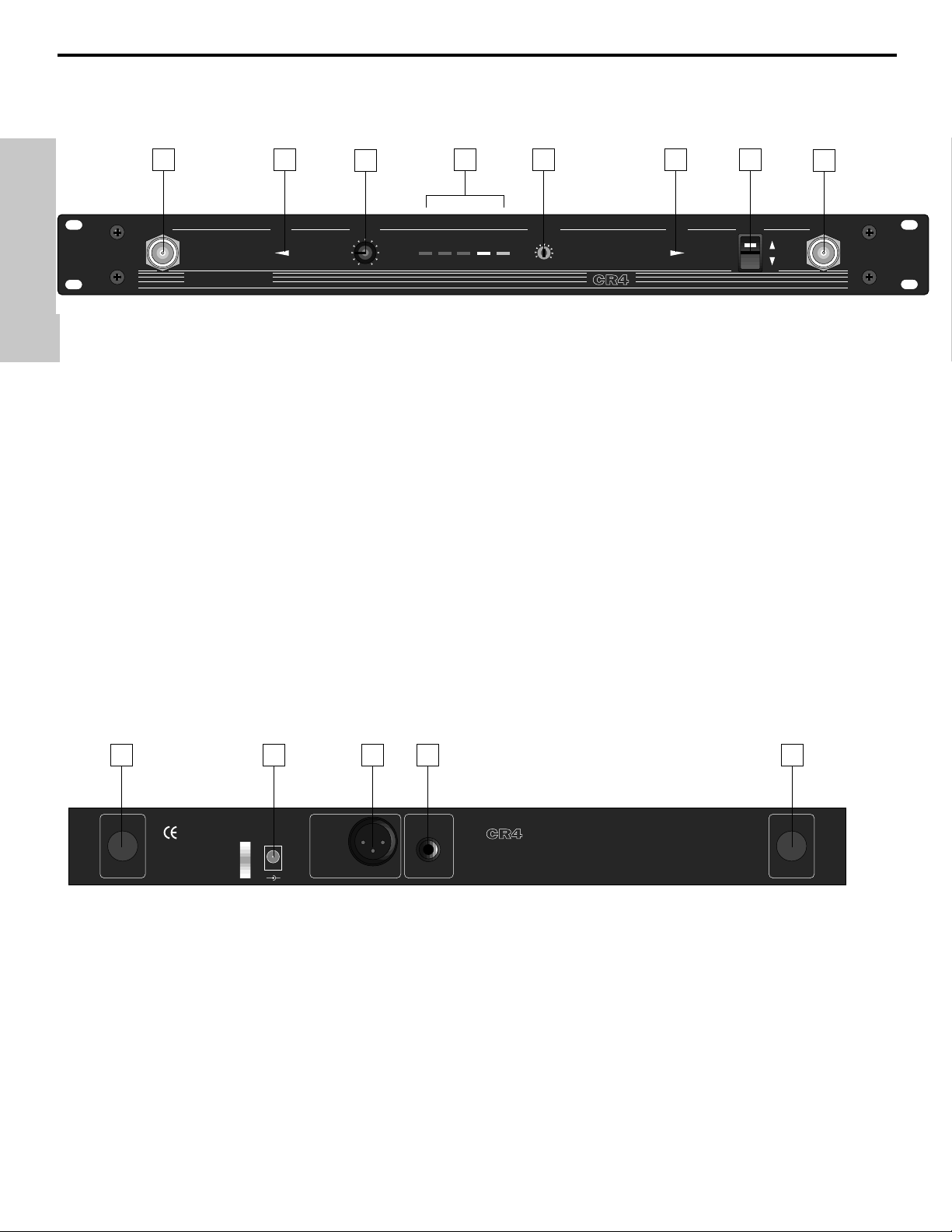
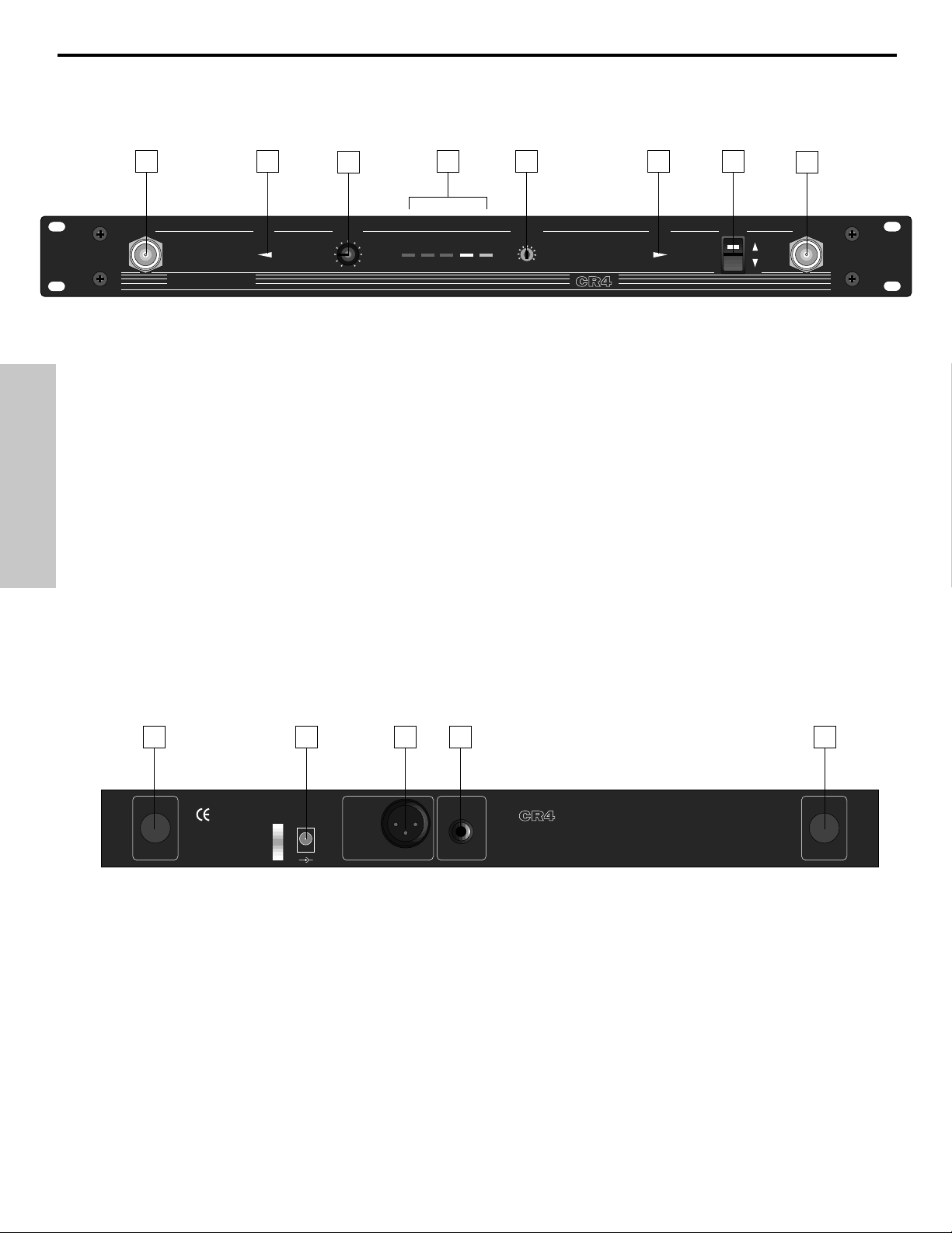
Guided Tour - CR4 Receiver
1: Antenna A and B mountings - Connect the supplied antennas to these mountings. Third-party receiver
antennas should not be substituted—use only the antennas provided with the CR4. See the “Setting Up and
Using the Concert IV System” section on page 6 for more about antenna installation and positioning.
2: Volume - This knob determines the level of the audio signal sent from both the balanced and unbalanced
output jacks on the rear panel.
3: “A”/“B” LEDs - When signal is being received, one of these LEDs will be lit, showing you whether signal from
either the “A” or “B” antenna is currently being used. A computer chip inside the CR4 constantly scans the two
and automatically selects whichever is receiving the strongest, clearest signal. This “Microprocessor True
Diversity” switching is completely inaudible, and it effectively increases overall range while reducing potential
interference and phase cancellation problems.
4: AF Level meter - This “ladder” display (similar to the VU bar meter used on audio devices) indicates the
strength of the incoming audio signal. When the “100%” segment is lit, the incoming signal is optimized at unity
gain; when the “125%” segment is lit, the signal is overloading. When only the left-most “10%” segment is lit, the
incoming signal is at just 10% of optimum strength. If no segments are lit, little or no signal is being received.
For more information, see the “Setting Up and Using the Concert IV System” section on page 6 in this manual.
5: Squelch control - This control determines the maximum range of the CR4 before audio signal dropout.
It should normally be left at its factory setting. For more information, see the “Setting Up and Using the Concert IV
System” section on page 6 in this manual.
6: Power switch - Use this to turn the main power on and off.
7: Rear-mount antenna knockouts - The CR4 antennas (normally mounted on the front panel) can optionally
be mounted on these areas of the rear panel. Contact Samson or your local distributor for further information.
8: DC input - Connect the supplied AC adapter here. WARNING: Do not substitute any other kind of power
adapter; doing so can cause severe damage to the unit and will void your warranty.
9: Balanced output* - Use this electronically balanced low impedance (600 Ohm) XLR plug when connecting the
CR4 to the microphone input of professional (-30 dBm) audio equipment, wired as follows: Pin 1 ground, Pin 2
high (hot), and Pin 3 low (cold).
10: Unbalanced output* - Use this unbalanced high impedance (5K Ohm) 1/4" jack when connecting the CR4 to
the microphone input of consumer (-10 dBv) audio equipment, wired as follows: tip hot, sleeve ground.
* If required, both the balanced and unbalanced outputs can be used simultaneously.
ANT.A VOLUMEANT.A ANT.B POWER ANT.B
1
VHF TRUE DIVERSITY
WIRELESS SYSTEM
SAMSON
2
5
6
4
3
7
8
2
9
1
0
10
AF LEVEL
10% 25% 75% 100% 125%
SQUELCH
max
min
CONCERT IV
33 4 5 6
1
ON
OFF
7
ANTENNA - B ANTENNA - A
PLUG LOCK
FOR AC
ADAPTOR
8 9 10
DC INPUT
12V=DC
2.4W (200mA)
+
BALANCED
OUTPUT
1. GND
2. HIGH
3. LOW
-
-30 dBm 600Ω
UNBALANCED
OUTPUT
-10dB 5KΩ
RECEIVER
SAMSON
MADE IN U. S. A.
FCC ID: CCRCR4
THIS DEVICE COMPLIES WITH PART 15 OF THE FCC RULES.
OPERATING IS SUBJECT TO THE FOLLOWING TWO CONDITIONS:
1. THIS DEVICE MUST NOT CAUSE HARMFUL INTERFERENCE AND
2. THIS DEVICE MUST ACCEPT ANY INTERFERENCE RECEIVED
INCLUDING INTERFERENCE THAT MAY CAUSE UNDESIRED OPERATION
CAUTION: USE 12VDC OUTPUT ADAPTER ONLY
ATTENTION: ANTENNA INPUT CONNECTORS ARE PHANTOM POWERED
BY DC 9V/25mA MAX. DO NOT SHORT
TECHNOLOGIES CORP., NEW YORK, U. S. A.
SAMSON
7
Page 5
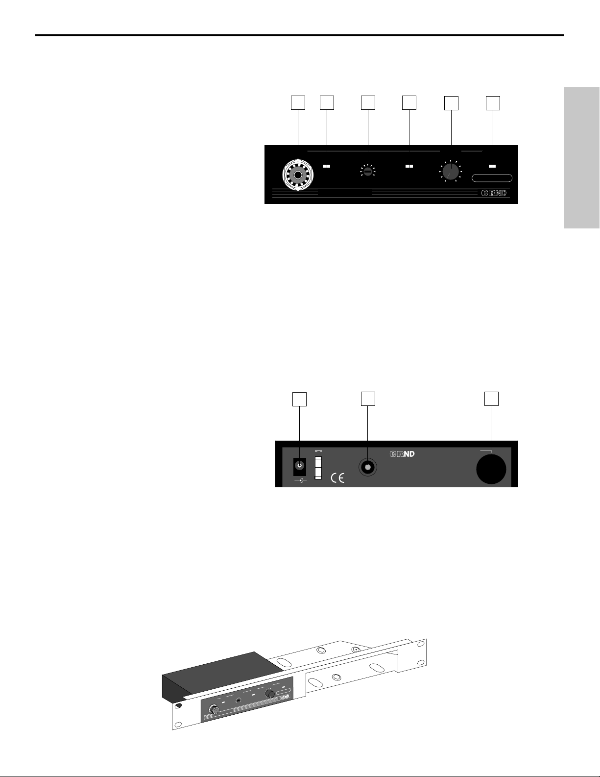
Guided Tour - CRND Receiver
1: Antenna mounting - Connect the
supplied antenna to this mounting.
Third-party receiver antennas should
not
be substituted—use only the antenna
provided with the CRND. See the
“Setting Up and Using the Concert IV
System” section on page 6 for more about
antenna installation and positioning.
2: “TX ON” LED - Lights when carrier
signal of sufficient strength is being
received by the CRND.
3: Squelch control - This control determines the maximum range of the CRND before audio signal
dropout. It should normally be left at its factory setting. For more information, see the “Setting Up and
Using the Concert IV System” section on page 6 in this manual.
4: Peak LED - This LED lights when output signal from the CRND is at the onset of clipping (that is,
when it is on the verge of being distorted). If you see this light during operation, move the microphone
further away or lower the output level of your instrument or transmitter. For more information, see the
“Setting Up and Using the Concert IV System” section on page 6 in this manual.
5: Volume - This knob determines the level of the audio signal sent from the unbalanced output jack on
the rear panel.
6: Power LED - Lights whenever the CRND is powered on.
7: DC input - Connect the supplied AC
adapter here. WARNING: Do not substitute
any other kind of power adapter; doing so
can cause severe damage to the unit and
will void your warranty.
8: Unbalanced output - Use this
unbalanced high impedance (5K Ohm)
1/4" jack to connect the CRND to the
microphone input of your mixer. The jack is
wired as follows: tip hot, sleeve ground.
9: Rear-mount antenna knockout - The CRND antenna (normally mounted on the front panel) can
optionally be mounted on this area of the rear panel. Contact Samson or your local distributor for further
information.
Rack-mounting the CRND
As shown in the illustration below, one or two CRND receivers can be mounted in a single 19" rack space
with the use of an optional adapter available from Samson or your local distributor.
5
ENGLISH
ND
lV
2
1
3
4
5
ANTENNA
TX ON
SQUELCH
min max
SAMSON
PEAK
CONCERT
VHF RECEIVER
3
2
1
VOLUME
5
4
0
6
7
9
10
8
Channel 16
6
POWER
7
8 9
DC INPUT 12V
1.2 W(100 mA)
+
UNBALANCED
FOR AC
OUTPUT
-10 dBv 5 K Ω
PLUG LOCK
ADAPTER
-
RECEIVER
SAMSON
MADE IN U.S.A.
CAUTION USE 12 VDC
OUTPUT ADAPTER ONLY
ANTENNA
A
ANTENN
SAMSON
R
E
W
PO
E
LUM
VO
6
5
4
7
K
PEA
3
8
LCH
UE
SQ
N
TX O
O
C
x
H
a
V
m
in
m
Channel 16
2
9
1
0
1
0
T
ER
C
R
E
N
IV
E
C
E
R
F
Page 6
6
ENGLISH
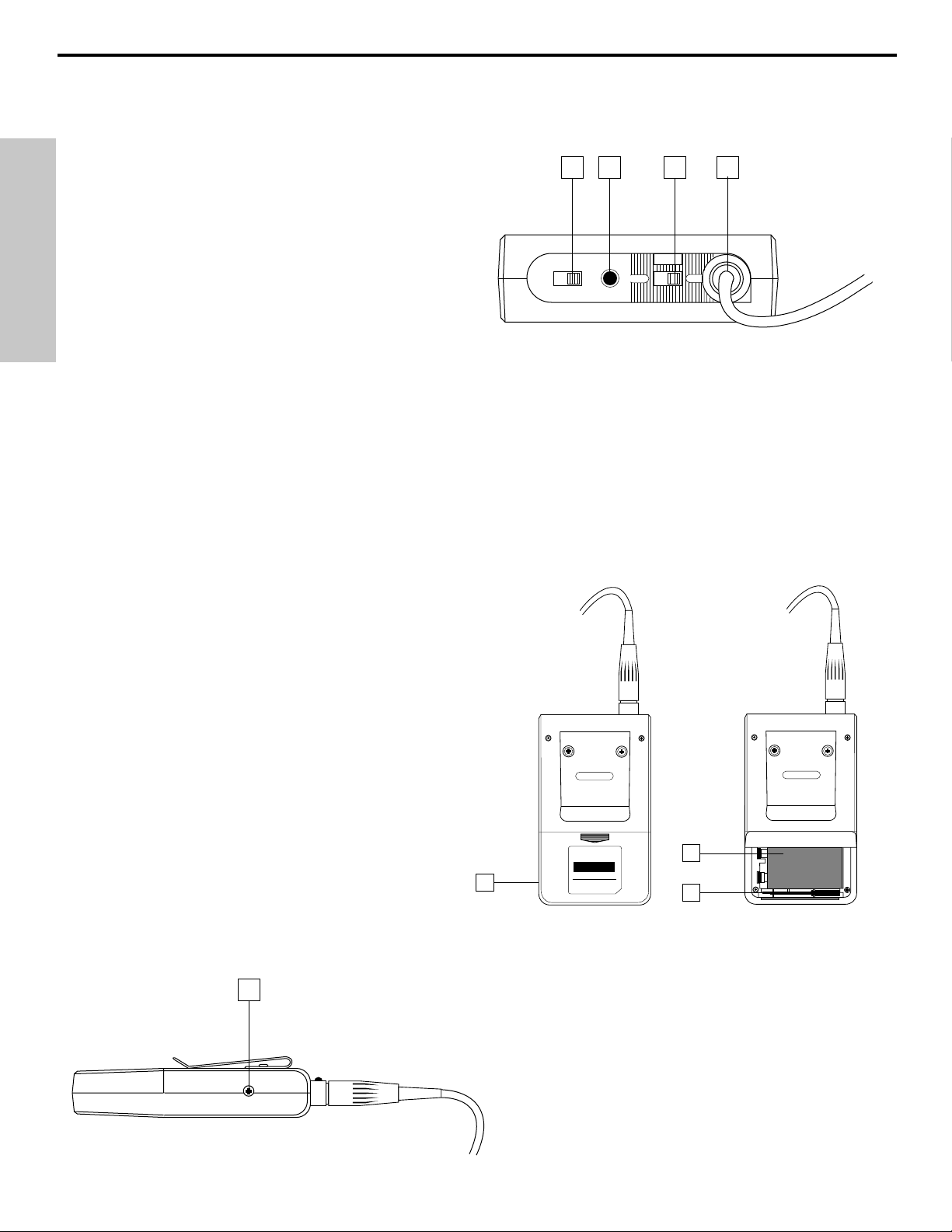
Guided Tour - CT4L / CT4G Beltpack Transmitter
1: Mute on-off switch - When set to the “Off”
position, audio signal is transmitted. When
set to the “On” position, the audio signal is
muted. The advanced circuitry in the
Concert IV system ensures that no “pop” or
“thud” will be heard during muting. Note that
turning this on does
not turn off the CT4L /
CT4G power—it is simply a way to temporarily
mute the transmission of audio signal. If you
don’t plan on using the CT4L / CT4G for
extended periods, turn off its power by using
the power on-off switch (see #3 below).
2: Battery LED - This LED is an indicator of battery strength. When the CT4L / CT4G is first powered on, this
LED will light for about two-tenths of a second (if the battery is sufficiently strong), and will then go off. When
battery voltage is low, this LED lights steadily, indicating that the battery needs to be replaced.
3: Power on-off switch - Use this to turn the CT4L / CT4G on or off (to conserve battery power, be sure to leave
it off when not in use). WARNING: Be sure to mute the audio signal at your external mixer or amplifier before
turning the CT4L / CT4G power on or off, or an audible pop may result.
4: Input connector - The input device is connected here. The CT4L is supplied with either a lavalier or headset
microphone (connected via a Switchcraft mini-XLR plug, as shown in the illustration above), while the CT4G is
supplied with a permanently connected 1/4" plug cable.
5: Battery door - Opening the CT4L / CT4G battery door must be done with care. See the “Setting
Up and Using the Concert IV System” section on
page 6 in this manual for more information.
6: Battery holder - Insert a standard 9-volt alkaline
battery here, being sure to observe the plus and
minus polarity markings shown. We recommend
the Duracell MN 1604 type battery. Although
rechargeable Ni-Cad batteries can be used, they
do not supply adequate current for more than four
hours.
WARNING: Do not insert the battery
backwards; doing so can cause severe damage to
the CT4L / CT4G and will void your warranty.
7: Plastic screwdriver - Specially designed for use
in adjusting the CT4L / CT4G Level control (see #8
below) and/or receiver Squelch control (see the
“Guided Tour: CR4,” “Guided Tour: CRND” and
“Setting Up and Using the Concert IV System”
sections on pages 2, 3 and 6 in this manual.
8: Audio Input Level control (trimpot) - This input
sensitivity control has been factory preset to provide
optimum level for the particular lavalier or headset
model being used (in the case of the CT4G, it is preset
for optimum instrument level) and so we recommend
that this not be adjusted manually. If necessary, however, you can use the supplied plastic screwdriver to
raise or lower the CT4L / CT4G input level. See the
“Setting Up and Using the Concert IV System” section
on page 6 in this manual for more information.
4L
1 2 3 4
MUTE
ON
OFF ON
POWER
OFF
8
Channel 11
OPEN
VHF BELTPACK TRANSMITTER
Model
CT
FCC ID CCRVT-1
SAMSON
5
Technologies Corp.
New York U.S.A.
6
7
Channel 10
SAMSON
Page 7
7
ENGLISH
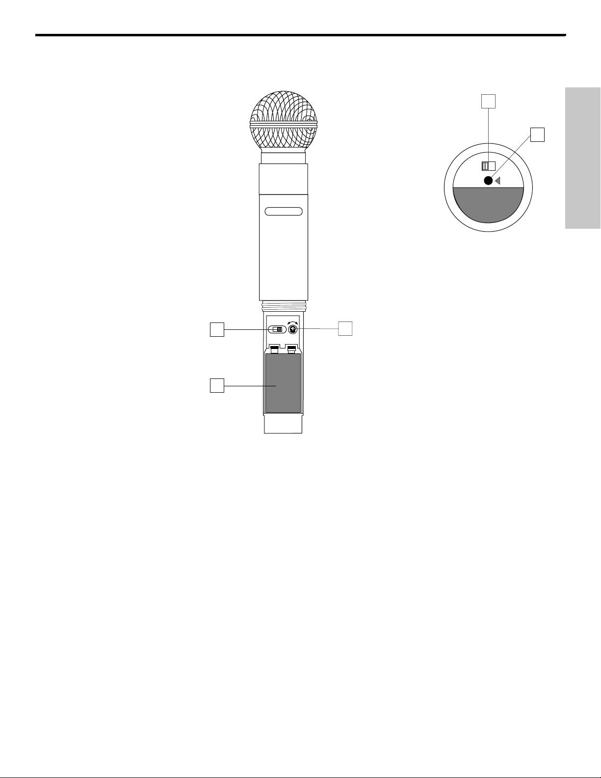
Guided Tour - HT4 Handheld Microphone Transmitter
1: Audio on-off switch - When set to the “On” position, audio signal is transmitted. When set to the
“Off” position, the audio signal is muted. The advanced circuitry in the Concert IV system ensures that
no “pop” or “thud” will be heard during muting. Note that turning this off does not turn off the transmitter
power—it is simply a way to temporarily mute the transmission of audio signal. If you don’t plan on using
the transmitter for extended periods, turn off the transmitter power by using the power on-off switch (see
#3 below).
2: Battery LED - This LED is an indicator of battery strength. When the HT4 is first powered on, this
LED will light for about two-tenths of a second (if the battery is sufficiently strong), and will then go off.
When battery voltage is low, this LED lights steadily, indicating that the battery needs to be replaced.
3: Power on-off switch - Use this to turn the HT4 on or off (to conserve battery power, be sure to leave
it off when not in use). WARNING: Be sure to mute the audio signal at your external mixer or amplifier
before turning transmitter power on or off, or an audible pop may result.
4: Mic level control (trimpot) - Determines the overall output level of the HT4. Use the supplied plastic
screwdriver to set this to the optimum microphone output level. See the “Setting Up and Using the
Concert IV System” section on page 6 in this manual for more information.
5: Battery holder - Insert a standard alkaline 9-volt battery here, being sure to observe the plus and
minus polarity markings shown. We recommend the Duracell MN 1604 type battery. Although
rechargeable Ni-Cad batteries can be used, we do not recommend them as they do not supply adequate
current for more than two hours.
WARNING: Do not insert the battery backwards; doing so can cause
severe damage to the HT4 and will void your warranty.
1
2
Audio
OnOff
Batt
SAMSON
SAMSON
MIN MAX
OFF ON
3
POWER LEVEL
E
1
0
4
Model HT4
Ch 11
5
Page 8
8
ENGLISH
Setting Up and Using the Concert IV System
The basic procedure for setting up and using your Concert IV VHF Wireless System takes only a few
minutes:
1. For the Concert IV system to work correctly, both the receiver and transmitter must be set to the same
channel. Remove all packing materials (save them in case of need for future service) and check to make
sure that the enclosed receiver and transmitter are set to the same channel (this is listed on the front
panel of the CR4 and CRND, on the belt clip of the CT4L and CT4G, and on the bottom of the HT4. If
these channels do not match, contact Samson Technical Support at 1-800-372-6766.
2. Mount the supplied antennas into your receiver (the CR4 has two antennas while the CRND has one)
by inserting the M connector and turning the outer ring clockwise until snug. Start by placing one or both
antennas in a vertical position; this will suffice for most environments. Insert the included Allen wrench
into the front of each antenna and turn clockwise to lock it into position.
3. Set the Power on-off switch in your CT4L / CT4G beltpack or HT4 handheld transmitter to “Off.”
4. If you are using a CT4L or CT4G transmitter, locate the Open arrow on the rear of its battery door and
press down and forward (away from the belt clip), then lift up. The battery door is hinged and not
intended to be removed from the transmitter case. Please use care when opening this door as undue
force will destroy the hinge. If you are using an HT4 transmitter, unscrew the bottom section of the
microphone by turning it counterclockwise and then slide it off.
5. Place a fresh 9-volt alkaline battery in the transmitter battery holder, taking care to observe the polarity
markings. If you are using a CT4L or CT4G transmitter, replace the battery door by swinging it down so
that it is parallel with the rear panel and then gently pushing upward towards the belt clip. Whichever
transmitter you are using, leave it switched off for the moment.
6. Make the physical cable connection between the output of your receiver (if you have a CR4, you can
use either or both of the balanced or unbalanced jacks) and the microphone level input of your amplifier
or mixer. If you have a CR4 and are using professional (-30 dBm) equipment, the balanced jack is
preferable since it will deliver an electromagnetically cleaner signal. Leave the amplifier (and/or mixer) off
at this time.
7. Turn the Volume knob on the front panel of the receiver completely counterclockwise (to the “0”
position). Connect the supplied AC adapter to the DC Input on the receiver’s rear panel, using the plug
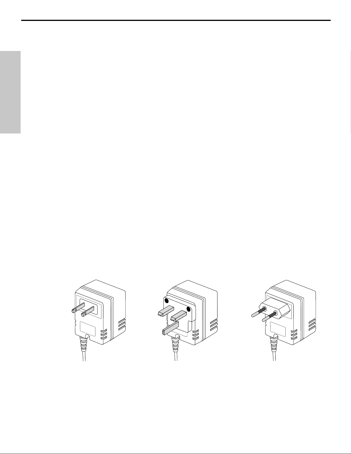
lock, then plug the adapter into any standard AC outlet. If you have a CR4, press the front-panel power
switch to turn the unit on. Note that the Samson CR4 / CRND AC adapter is available with three different
plug types so it can be used in the United States, United Kingdom, or other European countries.
8. Turn on the power to the CT4L, CT4G or HT4 transmitter (using its Power on-off switch); the “Battery”
LED should briefly light if the battery is good. If you are using an HT4 transmitter, replace the bottom
section of the microphone by sliding it on and then screwing it back on. Once the transmitter is powered
on, either the “TX ON” LED (in the CRND) or either the “A” or “B” LED on the CR4 front panel will light
(showing which antenna is receiving the stronger signal).
9. Now it’s time to set the audio levels. Turn on your connected amplifier and/or mixer but keep its
volume all the way down. Next, make sure that your transmitter is unmuted, as follows:
US version
UK version European version
Page 9
ENGLISH
Setting Up and Using the Concert IV System
• If you are using a CT4L or CT4G transmitter, set the Mute switch to “Off”
• If you are using an HT4 transmitter, set the Audio switch to “On”
IF YOUR SYSTEM HAS A CR4 RECEIVER, FOLLOW THE INSTRUCTIONS IN THIS PARAGRAPH:
If you are using the HT4 transmitter (or if you are using the CT4L transmitter with a connected lavalier
microphone or headset), speak or sing into the mic at a normal performance level while observing the
CR4 front panel AF Level meter. If you are using the CT4G transmitter with a connected instrument,
play the instrument at normal performance level while observing the CR4 front panel AF Level meter.
If the “100%” (unity gain) segment is lighting steadily, with just occasional higher excursions, the audio
level is correctly set. If not, use the supplied plastic screwdriver to slowly adjust the HT4, CT4L, or CT4G
Level control (trimpot) until the CR4 AF Level meter “100%” (unity gain) segment lights steadily (with
occasional higher excursions). Then slowly raise the CR4 Volume knob to the 2 o’clock position (unity
gain) and set the volume of your amplifier/mixer until the desired level is reached.
IF YOUR SYSTEM HAS A CRND RECEIVER, FOLLOW THE INSTRUCTIONS IN THIS PARAGRAPH.
Begin by setting your amplifier/mixer to a low listening level. If you are using the HT4 transmitter (or if
you are using the CT4L transmitter with a connected lavalier microphone or headset), speak or sing into
the mic at a normal performance level while slowly raising the CRND front panel Volume knob to the
2 o’clock position (unity gain). If you are using the CT4G transmitter with a connected instrument, play
the instrument at normal performance level while slowly raising the CRND front panel Volume knob to the
2 o’clock position. Finally, set the volume of your amplifier/mixer until the desired level is reached.
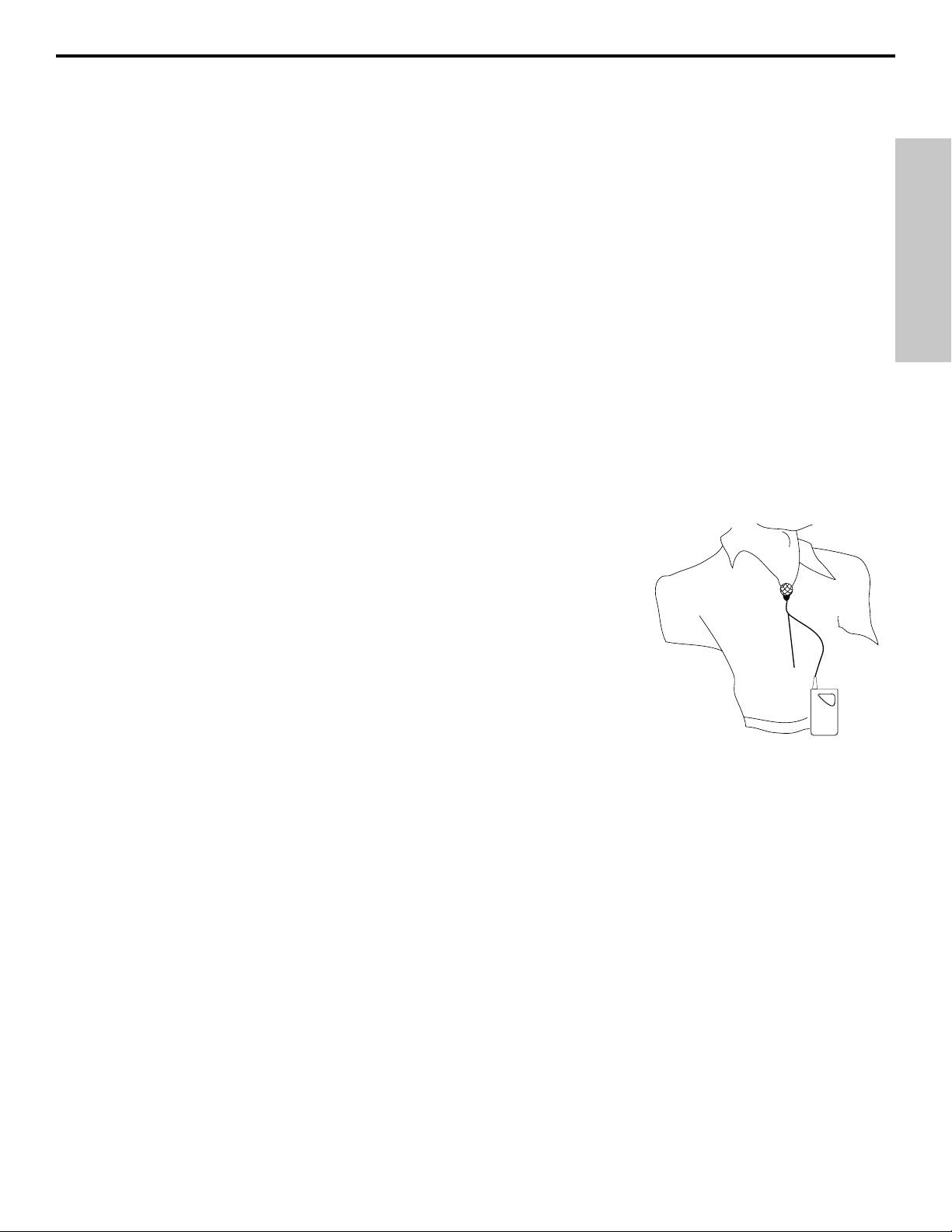
THIS PARAGRAPH AND ALL SUBSEQUENT ONES APPLY TO ALL CONCERT IV
SYSTEMS. If you are using a CT4L beltpack transmitter equipped with a lavalier
microphone, note that correct lavalier placement is critical to sound quality.
We recommend that you place it as shown in this illustration—as close to your mouth
as possible but off to one side (to minimize nasality) and unobstructed by clothing.
Bear in mind also that
omni microphones (mics which pick up signal from all direc-
tions) are more prone to feedback problems than
unidirectional (cardioid or
supercardioid) ones; in general, you can avoid feedback by taking care not to use
any microphone directly in front of a PA speaker (if this is unavoidable, try using an
equalizer to attenuate those high- or mid-range frequencies which are causing the
feedback “squealing”).
10. If you hear distortion at the desired volume level (or, if you have a CR4 and its
AF Level meter “125%” segment is lighting frequently), first make sure that the gain structure of your
audio system is correctly set (consult the owners manual of your mixer and/or amplifier for details). If it is
and distortion is still present, do the following:
• If you are using an HT4 transmitter, use the supplied plastic screwdriver to turn its Level control
(trimpot) slowly counterclockwise (towards the “Min” position) until the distortion disappears.
• If you are using a CT4L transmitter with connected lavalier microphone or headset, its Level control
has been factory preset to provide optimum level for the particular lavalier or headset model being
used and so no adjustment should be necessary. Any distortion present should therefore simply be a
matter of the microphone being too close to the mouth; try moving it further away. If this does not
solve the problem, use the supplied plastic screwdriver to turn the Level control (trimpot) on the CT4L
slowly counterclockwise until the distortion disappears.
• If you are using a CT4G transmitter with an instrument such as electric guitar or bass, lower the
output level of the instrument until the distortion disappears. Alternatively, you can use the supplied
plastic screwdriver to turn the Level control (trimpot) on the CT4G slowly counterclockwise until the
distortion disappears.
Note that, following this setup procedure, you can always lower the Volume of the CR4 or CRND in order
to attenuate the output signal if necessary.
11. Conversely, if you hear a weak, noisy signal at the desired volume level (or, if you have a CR4 and
its AF Level meter “100%” segment is not being lit), again make sure that the gain structure of your audio
system is correctly set. If it is and the signal coming from the receiver is still weak and/or noisy, do the
following:
9
SAMSON
CT4L
Page 10

10
ENGLISH
Setting Up and Using the Concert IV System
• If you are using an HT4 transmitter, use the supplied plastic screwdriver to turn the Level control
(trimpot) on the transmitter slowly clockwise (towards the “Max” position) until the signal reaches an
acceptable level.
• If you are using a CT4L transmitter with connected lavalier microphone or headset, its Level control
has been factory preset to provide optimum level for the particular lavalier or headset model being
used and so no adjustment should be necessary. Any weakness of signal should therefore simply be
a matter of the microphone being too far from the mouth; try moving it closer. If this does not solve
the problem, use the supplied plastic screwdriver to turn the Level control (trimpot) on the CT4L
slowly clockwise until the signal reaches an acceptable level
• If you are using a CT4G transmitter with an instrument such as electric guitar or bass, raise the
output level of the instrument until a good signal is achieved. Alternatively, use the supplied plastic
screwdriver to turn the Level control (trimpot) on the CT4G slowly clockwise until the signal reaches
an acceptable level.
Note that, following this setup procedure, you can always raise the Volume of the CR4 or CRND in order
to boost the output signal if necessary.
12. Temporarily turn down the level of your mixer/amplifier system and turn off the power to your CT4L,
CT4G or HT4 transmitter, leaving the receiver on. Then restore the previously set level of your
mixer/amplifier. With the transmitter off, the receiver output should be totally silent—if it is, skip ahead to
the next step. If it isn’t (that is, if you hear some noise), you may need to adjust the CR4 or CRND front
panel Squelch control. When the Squelch control is at its minimum setting, the Concert IV system always
provides maximum range without dropout; however, depending upon the particular environment your
system is used in, you may need to reduce that range somewhat in order to eliminate band noise when
the transmitter is turned off. To do so, use the provided screwdriver to rotate the Squelch control
completely counterclockwise (to the “Min” position), then slowly turn it clockwise until the noise
disappears. If no noise is present at any position, leave it at its fully counterclockwise “Min” position
(so as to have the greatest overall range available).
13. When first setting up the Concert IV system in a new environment, it’s always a good idea to do a
walkaround in order to make sure that coverage is provided for your entire performance area.
Accordingly, turn down the level of your audio system and turn on both the CT4L, CT4G or HT4
transmitter and CR4 or CRND receiver. Then, with the transmitter unmuted, restore the level of your
audio system and while speaking, singing, or playing your instrument, walk through the entire area that
will need to be covered. If you have a CR4 receiver, note that, as you do so, the “A” and “B” LEDs on the
front panel occasionally switch on or off, always showing you which antenna is receiving the stronger
signal. The basic rule of thumb for all wireless audio systems is to always try to minimize the distance
between transmitter and receiver as much as possible and also to try to maintain “line of sight” between
the two (that is, the person using the transmitter should be able to see the receiver antennas). The idea
is to ensure that the strongest possible signal is received from all planned transmission points. In fixed
installations such as A/V or corporate conference rooms or for extended range applications (where the
transmitter and receiver are more than 150 feet apart), it may be desirable to angle the antennas
differently from their vertical position (use the supplied Allen wrench to loosen and then retighten the
seating), mount them on the rear of your receiver (using the provided knockouts and a Rear Mount
Antenna Kit available from Samson or your local distributor) or even to remote the receiver antennas
altogether. Remoting can be accomplished by using standard M connectors and low-capacitance coaxial
cabling (50 ohm or better) that is suitable for up to 1 gigaHertz bandwidth usage. The lower the
capacitance of the cable, the further you can remote the antennas.
If you have followed all the steps above and are still experiencing difficulties, call Samson Technical
Support (1-800-372-6766) between 9 AM and 5 PM EST.
NOTE: The Concert IV system is designed to replace the wire that is used in wired microphone systems,
providing a gain ratio of 1 : 1.5. Therefore, when using a mixer that provides low impedance mic inputs,
always connect the CR4 or CRND receiver to those mic inputs as opposed to line-level (high impedance)
inputs. For the same reason, do not connect the receiver directly to the line-level input of signal processors; to apply effects to the receiver’s output signal, connect signal processors to mixer insert points.
Page 11

11
FRANCAIS
Introduction
Félicitations pour votre acquisition du système VHF Samson Concert IV! Bien que ce produit ait été
conçu en vue d’une simplicité d’utilisation, nous vous recommandons de prendre le temps de lire ces
quelques pages de manière à comprendre le nombre de caractéristiques uniques que nous avons
introduit.
Chaque système VHF consiste d’au moins deux composants - un émetteur et un récepteur, chacun
d’eux devant être accordé sur le même canal (à savoir, la même fréquence radio) afin de fonctionner
correctement*. Le système sans fil Samson Concert IV dont vous venez de faire l’acquisition contient un
récepteur de type CR4 ou CRND, ainsi qu’un des émetteurs suivants : le modèle ceinture CT4L
(applications avec micro Lavalier ou micro avec serre-tête), le modèle guitare CT4G (pour instruments
de musique) ou le microphone à main HT4.
L’ émetteur de ceinture CT4L dispose d’une mini prise XLR Switchcraft P3 compatible avec plusieurs
ensembles micro - casque et micro lavallières tels que: l’ ensemble micro-casque Audio Technica
ATM 75; le micro lavallière Audio Technica MT 350; l’ ensemble micro-casque Audio Technica
Pro-8HE; le micro lavallière Audio Technica 831H-7; l’ ensemble micro-casque Countryman Isomax;
l’ ensemble micro-casque Crown CM 311 (E); le micro lavallière Foster ECM 40; les ensembles
micro-casque Samson QV et Samson QE**; le micro lavallière Sennheiser MKE 2; les micros lavallières
Sony ECM 44, Sony ECM 55 et Sony ECM 77. L’ émetteur HT4 pour micros tenus à la main est
disponible pour plusieurs modèles courants de capsules tels que: Electro Voice
ND 757 A N/DYM
dynamique; Electro Voice ND 857 N/DYM dynamique; Electro Voice BK 1 électrostatique; Samson
Q MIC dynamique; Sennheiser MKE 4032 électrostatique; Shure SM58 dynamique; Shure SM85
électrostatique et Shure SM87 électrostatique.
Le récepteur CRND livré avec certains systèmes sans fil Concert IV fait appel à la technologie non
Diversity et comprend une seule antenna, pour une facilité d’utilisation accrue et un prix minimal. Les
systèmes équipés d’un récepteur CR4 utilisent une technologie brevetée réellement novatrice appelée
“Microprocessor True Diversity”*** (système de conception Diversity véritable à microprocesseur) faisant
appel à deux antennes (appelees A et B) et un circuit de réception rassemblés sur un châssis unique.
Un microprocesseur scanne continuellement les signaux radios provenant des deux antennes et
détermine lequel des deux signaux est le plus fort et le plus clair, automatiquement (et silencieusement)
routant ce signal au récepteur. Cela vous permet une liaison radio couvrant un champ plus large que ce
que vous obtiendriez avec un récepteur n’utilisant qu’une seule antenne, de plus cela élimine quasiment
tout problème d’ interférence et d’ annulation de phase. En addition, un circuit spécial “sample and hold”
permet de garder une relation de phase correcte et constante, sans bruit ni “pops” au changement d’une
antenne à l’autre. Le résultat en performance excède celui des systèmes conventionnels (true diversity)
et assure la plus haute qualité de reproduction audio parmi tous les systèmes UHF disponibles
actuellement. Enfin, l’utilisation systématique du circuit de réduction du bruit Signetics® sur tous les
systèmes Concert IV permet d’obtenir un son cristallin exempt de bruit de fond et de souffle.
Dans ce manuel, vous trouverez une description détaillée des caractéristiques du système Concert IV,
ainsi qu’un parcours guidé de tous les composants, des instructions claires pour mettre en place et
utiliser votre système avec toutes les spécifications. Vous trouverez aussi une carte de garantie n’oubliez pas de la remplir et de la renvoyer! Cela vous permettra de recevoir un support technique et
nous donnera l’ occasion de vous faire parvenir les dernières informations sur de nouveaux produits
Samson a venir.
* Votre récepteur et émetteur on été pré-réglés a l’usine sur le même canal.
** Optimisé pour aerobics, cet ensemble micro - casque étanche est recommandé pour utilisation dans
des environnements a haute humidité tels que les centres de gymnastique.
*** “Microprocessor True Diversity”
Page 12
12
FRANCAIS
Parcours Guidé - Récepteur CR4
1: Connecteurs d’Antenne A et B - Adaptez à ces connecteurs les antennes fournies.Les antennes provennant
d’ autres fournisseurs devraient être évitées- utilisez exclusivement les antennes fournies avec le CR4. Voir page
14 pour plus d’information sur l’ installation et le positionnement des antennes.
2: Volume - Ce potentiomètre détermine le niveau de signal audio aux sorties symétriques et asymétriques à
l’arrière du rack.
3: LEDs “A” /”B” - Lorsqu’un signal est reçu, l’une de ces LEDs s’allumera vous indiquant si le signal de
l’antenne “A” ou “B” est actuellement utilisé. Un micro-processeur scanne continuellement les signaux radios
provenant des deux antennes et détermine lequel des deux signaux est le plus fort et le plus clair. La transition
“MTD” est totalement inaudible, élargît le champ de réception et réduit les problèmes d’ interference et de relation
de phase.
4: Indicateur de niveau AF - Cet indicateur de niveau (similaire au VU metre utilisé en équipement audio)
montre la force du signal audio. Quand le segment 100% est allumé, le signal de sortie est optimal, quand le
segment 125% est allumé, il y a surcharge de signal. Quand seul le segment 10% de gauche est allumé, le
signal de sortie est a seulement 10% du niveau optimal. Si aucun segment n’est allumé, il n’y a peu ou pas de
signal en sortie. Pour plus d’ information, voir page 14 de ce manuel.
5: Contrôle de Squelch - Ce contrôle détermine le champ d’action maximal avant perte de signal. Le réglage
d’usine devrait être conservé. Pour plus d’information, voir page 14 de ce manuel.
6: Commutateur d’alimentation - Power - Utiliser pour allumer ou éteindre le récepteur.
7: Emplacement pour connecteurs d’antennes - Les antennes du CR4 (normalement montées sur la face
avant du rack) peuvent, en option, être montées à l’ arrière. Contactez Samson ou votre distributeur local pour
information sur le Kit de montage d’antenne à l’ arrière.
8: Connecteur d’alimentation - Connectez ici l’alimentation fournie. ATTENTION: Ne pas utiliser d’autres
alimentations au risque de provoquer de graves dommages et d’annuler votre garantie.
9: Sortie symétrique* - Utilisez cette sortie XLR symétrique basse impédance (600 Ohm) lorsque vous
connectez le CR4 à l’entrée micro d’ un équipement audio professionnel (-30dBm). Câblez comme suit Broche 1
masse; broche 2 chaud et broche 3 froid.
10: Sortie asymétrique* - Utilisez cette sortie jack 1/4" asymétrique haute impédance (5K Ohm) lorsque vous
connectez le CR4 à l’entrée micro d’ un équipement audio semi-pro ou domestique (-10dBv). Pointe, sous
tension; gaine, masse.
* Si nécessaire, les sorties asymétriques et symétriques peuvent être utilisées simultanément.
1
ANT.A VOLUMEANT.A ANT.B POWER ANT.B
SAMSON
VHF TRUE DIVERSITY
WIRELESS SYSTEM
2
5
6
4
3
7
8
2
9
1
0
10
AF LEVEL
10% 25% 75% 100% 125%
SQUELCH
min
max
CONCERT IV
33 4 5 6
1
ON
OFF
7
ANTENNA - B ANTENNA - A
PLUG LOCK
FOR AC
ADAPTOR
8 9 10
DC INPUT
12V=DC
2.4W (200mA)
+
BALANCED
OUTPUT
1. GND
2. HIGH
3. LOW
-
-30 dBm 600Ω
UNBALANCED
OUTPUT
-10dB 5KΩ
RECEIVER
SAMSON
MADE IN U. S. A.
FCC ID: CCRCR4
THIS DEVICE COMPLIES WITH PART 15 OF THE FCC RULES.
OPERATING IS SUBJECT TO THE FOLLOWING TWO CONDITIONS:
1. THIS DEVICE MUST NOT CAUSE HARMFUL INTERFERENCE AND
2. THIS DEVICE MUST ACCEPT ANY INTERFERENCE RECEIVED
INCLUDING INTERFERENCE THAT MAY CAUSE UNDESIRED OPERATION
CAUTION: USE 12VDC OUTPUT ADAPTER ONLY
ATTENTION: ANTENNA INPUT CONNECTORS ARE PHANTOM POWERED
BY DC 9V/25mA MAX. DO NOT SHORT
TECHNOLOGIES CORP., NEW YORK, U. S. A.
SAMSON
7
Page 13

Parcours Guidé - Récepteur CRND
13
FRANCAIS
1: Montage de l’antenna - Fixez l’antenne
fournie sur son support. N’utililisez en aucun cas
une autre antenne que celle livrée avec le
récepteur CRND. Consultez la page 14 pour
obtenir de plus amples renseignements sur
l’installation de l’antenna et son positionnement.
2: Led “TX ON” - Ce témoin lumineux indique la
recéption par le CRND d’un signal de puissance
suffisante.
3: Réglage de Squelch - Ce réglage détermine le seuil minimal du signal reçu par le récepteur CRND
avant coupure. Ce réglage doit en principe rester dans sa position telle qu’à la sortie de nos usines.
Pour obtenir de plus amples informations, veuillez consulter la section sur las mise en oeuvre et le
reglage du système Concert IV en page 14 de ce manuel.
4: Led Peak - Ce tèmoin s’ailume lorsque le signal de sortie du récepteur CRND arrive à écretage
(c’est-à-dire à la limite de la distorsion). Si ce tèmoin s’allume lors de l’utilisation, éloignez le micro ou
diminuez le niveau de sortie de l’instrument ou de l’émetteur. Pour obtenir de plus amples informations,
veuillez consulter la section sur las mise en oeuvre et le réglage du système Concert IV en page 14 de
ce manuel.
5: Volume - Ce réglage détermine le niveau de sortie du signal audio present sur la prise de sortie
asymétrique située en face arrière (Jack).
6: Tèmoin de mise sous tension - Cette Led s’allume lorsque le récepteur CRND est sous tension.
7: Prise d’antenne de face arrière - L’antenne du
récepteur CRND normalement située en façade
peut être montee en face arriere (en option).
Contactez votre revendeur pour tout renseignement
complémentaire concernant cette option.
8: Prise DC - Cette prise permet le branchement
de l’adaptateur secteur. ATTENTION: Veillez à ne
jamais utiliser un autre adaptateur secteur que celui
fourni par nos soins, au risque de causer de graves
dommages à l’appareil. Cette situation annulerait
automatiquement toute forme de garantie.
9: Sortie asymétrique - Utilisez cette prise Jack 6.35 mm asymétrique haute impédance (5 kOhms)
pour brancher le récepteur CRND sur une entrée micro de votre console de mixage. Le Jack est
branché comme suit : Extrémité = point chaud, Corps = masse/blindage.
Montage en rack du récepteur CRND
Comme indiquê sur l’illustration ci-dessous, vous pouvez installer un, voire deux récepteurs CRND dans
un rack 19 pouces 1 U grâce à l’adaptateur optionnel disponible chez votre revendeur.
ND
lV
2
1
3
4
5
ANTENNA
TX ON
SAMSON
SQUELCH
min max
PEAK
CONCERT
VHF RECEIVER
3
2
1
VOLUME
5
4
0
6
7
9
10
8
Channel 16
6
POWER
7
8 9
DC INPUT 12V
1.2 W(100 mA)
+
UNBALANCED
FOR AC
OUTPUT
-10 dBv 5 K Ω
PLUG LOCK
ADAPTER
-
RECEIVER
SAMSON
MADE IN U.S.A.
CAUTION USE 12 VDC
OUTPUT ADAPTER ONLY
ANTENNA
A
ANTENN
SAMSON
R
E
W
PO
E
LUM
VO
6
5
4
7
PEAK
3
8
LCH
UE
SQ
N
TX O
O
C
x
H
a
V
m
n
i
m
Channel 16
2
9
1
0
1
0
T
ER
C
R
E
N
IV
E
C
E
R
F
Page 14

14
FRANCAIS
Parcours Guidé - CT4L/ CT4G Emetteur de ceinture
1: Commutateur Mute on-off - Sur la position
“Off”, le signal audio est retransmis. Sur la
position “On” le signal audio est interrompu. La
qualité avancée du circuit du système Concert IV
assure qu’aucun bruit ne sera entendu à la
commutation. Notez que la commutation du
signal ne signifie pas que le CT4L/ CT4G n’est
plus alimenté - cela est simplement un moyen
d’interrompre temporairement la transmission du
signal audio. Si vous songez à ne pas utiliser le
CT4L/ CT4G pour une longue période, utilisez le
commutateur d’alimentation (power on-off, cf: #3
ci-dessous).
2: Témoin de pile - Cette LED est une indication de l’ état de votre pile. A la mise en marche du CT4L/ CT4G
cette LED va s’allumer pendant environ 2/10 de seconde (si votre pile le permets), et puis s’ éteindre. Quand la
puissance de la pile est faible, cette LED restera allumée pour vous indiquer que la pile doit être changée.
3: Commutateur d’Alimentation - Power on-off - Utiliser ce commutateur pour mettre en marche ou éteindre le
CT4L/ CT4G (assurez vous de le laisser sur “off” quand vous ne l’utilisez pas afin de ne pas user la pile).
ATTENTION: Afin d’éviter un “pop”, pensez à interrompre le signal audio à la table de mixage ou l’amplificateur
avant d’éteindre le CT4L/CT4G.
4: Connecteur d’ entrée - C’est ici que vous connectez le signal d’entrée. Le CT4L est disponible avec soit un
micro lavallière ou un ensemble micro-casque (connecté à une mini prise XLR Switchcraft, comme montré dans
l’ illustration ci-dessus), alors que le CT4G est pourvu d’un cordon jack 1/4” rattaché en permanence.
5: Accès Pile - Accéder le compartiment de la pile
doit être effectué avec soin; référez vous à la section
“Installation et Utilisation du système Concert IV” à la
page 14 de ce manuel pour plus d’ information.
6: Compartiment de la Pile - Insérez une pile
alcaline standard 9 volts en vous assurant de
respecter les polarités positives et négatives comme
indiqué par les repères. Nous recommandons le
modèle Duracell MN 1604. Bien que les piles Ni-Cad
rechargeables puissent être utilisées, elles ne
peuvent délivrer un courant adéquat pendant plus de
quatre heures.
ATTENTION : Ne pas insérez la pile
à l’envers; cela peut provoquer de graves dommages
au CT4L/ CT4G et annulerait votre garantie.
7: Tournevis plastique - Spécialement conçu pour
régler les niveaux des émetteurs CT4L et CT4G (voir
le paragraphe no. 8) et/ou le niveau de Squelch du
récepteur (consultez les pages 10, 11 et 14 de ce
manuel).
8: Contrôle de Gain Audio (trimpot) - Ce contrôle de gain
d’ entrée a été pré-reglé en usine de manière à assurer un niveau
optimum en fonction du modèle particulier de lavallière ou
ensemble micro-casque utilisé (le CT4G ayant été pré-reglé pour
un niveau d’instrument optimum), aussi nous vous recommandons
d’ éviter de le modifier manuellement. Malgré tout, si nécessaire,
vous pourrez utiliser le tournevis plastique fourni pour augmenter
ou réduire le niveau de gain du CT4L/ CT4G. Voir page 14 de ce
manuel pour plus d’information.
4L
1 2 3 4
MUTE
ON
OFF ON
POWER
OFF
5
Channel 11
OPEN
VHF BELTPACK TRANSMITTER
Model
CT
FCC ID CCRVT-1
SAMSON
Technologies Corp.
New York U.S.A.
Channel 10
6
7
SAMSON
8
Page 15

15
FRANCAIS
Parcours Guidé - Micro - émetteur à main HT4
1: Commutateur Audio on-off - Sur la position “On”, le signal audio est retransmis. Sur la position “Off”
le signal audio est interrompu. La qualité avancée du circuit du système Concert IV assure qu’aucun
bruit ne sera entendu à la commutation. Notez que la commutation du signal ne signifie pas que le HT4
n’est plus alimenté - cela est simplement un moyen d’interrompre temporairement la transmission du
signal audio. Si vous songez à ne pas utiliser le HT4 pour une longue période, utilisez le commutateur
d’alimentation (power on-off, cf: #3 ci-dessous).
2: Témoin de pile - Cette LED est une indication de l’ état de votre pile. A la mise en marche du HT4
cette LED va s’allumer pendant environ 2/10 de seconde (si votre pile le permets), et puis s’ éteindre.
Quand la puissance de la pile est faible, cette LED restera allumée pour vous indiquer que la pile doit
être changée.
3: Commutateur d’Alimentation - Power on-off - Utilisez ce commutateur pour mettre en marche ou
éteindre le HT4 (assurez vous de le laisser sur “Off” quand vous ne l’utilisez pas afin de ne pas user la
pile).
ATTENTION: Afin d’éviter un “pop”, pensez à interrompre le signal audio à la table de mixage ou
l’amplificateur avant d’éteindre le HT4.
4: Contrôle de gain - Détermine le niveau de sortie du HT4. Utilisez le tournevis plastique fourni pour
régler le niveau de gain optimum du microphone. Voir “Installation et Utilisation du système Concert IV”
à la page 14 de ce manuel pour plus d’information.
5: Compartiment de la Pile - Insérez une pile alcaline standard 9 volts en vous assurant de respecter
les polarités positives et négatives comme indiqué par les repères. Nous recommandons le modèle
Duracell MN 1604. Bien que les piles Ni-Cad rechargeables puissent être utilisées, elles ne peuvent
délivrer un courant adéquat pendant plus de deux heures.
ATTENTION : Ne pas insérez la pile a
l’envers; cela peut provoquer de graves dommages au HT4 et annulerait votre garantie.
1
2
Audio
OnOff
Batt
SAMSON
SAMSON
MIN MAX
OFF ON
3
E
POWER LEVEL
1
0
4
Model HT4
Ch 11
5
Page 16

16
FRANCAIS
Installation et Utilisation du système Concert IV
La procédure de base pour mettre en place et utiliser votre système Concert IV ne prends en fait que
quelques minutes:
1. Afin que le système Concert IV fonctionne correctement, le récepteur et l’ émetteur doivent être
accordés sur le même canal. Retirez les éleménts de leur embaliage (veillez à les conserver en cas de
maintenance) et vérifiez que l’émetteur et le récepteur utilisent le même canal H.F. (indiqué en façade du
CR4 et du CRND, sur la pince du CT4L et CT4G et sur la partie intérieure du HT4). Si ces canaux ne
sont pas identiques contacter le service technique de Samson au 1- 800-372-6766.
2. Montez l’antenne fournie sur le récepteur (le CR4 possede deux antennes, le CRND une seule) en
insérant la prise M dans l’embase et en vissant la bague extérieure jusqu’au serrage. Commencez par
placer au moins une des antennes en position verticale : cette configuration devrait suffire dans la
majorité des cas. Insérez la clé Allen, fournie, dans chaque antenne et tourner dans le sens des aiguilles
d’une montre pour verrouiller en position.
3. Assurez vous que le commutateur d’alimentation de l’ émetteur CT4L/CT4G ou de l’ émetteur HT4 est
sur la position “Off”.
4. Si vous utilisez un émetteur CT4L/ CT4G, localiser la flèche “Open” à l’arrière de l’ accès pile et
appuyer en poussant vers l’avant (dans le sens opposé à l’ attache ceinture), ensuite soulevez. L’accès
de la pile est sur charnière et n’ est pas supposé être détaché du boîtier de l’ émetteur. Faites attention
en ouvrant car trop de force casserait la charnière. Si vous utilisez un émetteur HT4, dévissez la base du
microphone en tournant dans le sens contraire des aiguilles d’une montre et faites la glisser pour
l’enlever.
5. Placez une pile alcaline 9 volt neuve dans le compartiment de l’ émetteur en vous assurant de
respecter les polarités comme indiqué. Si vous utilisez un émetteur CT4L/ CT4G, replacez l’ ouverture
du compartiment de manière à ce qu’elle soit parallèle à la face arrière et poussez doucement vers le
haut en direction de l’attache ceinture. Quelque soit l’ émetteur que vous utilisez attendez quelques
instants avant de le mettre en marche.
6. Utilisez un cable audio pour raccorder la sortie du récepteur (dans le cas du CR4, vous pouvez utiliser
indifféremment une ou les deux prises symétrique ou asymétrique) et l’entree micro de votre console.
Si vous utilisez un récepteur CR4 avec un matériel travaillant à niveau professionnel (-30 dBm), nous
vous conseillons d’utiliser la prise symétrique qui fournira un signal de meilleure qualite. N’allumez pas
l’amplificateur (et/ou mixeur) pour le moment.
7. Tournez le bouton de volume au minimum (position “0”). Branchez l’adaptateur secteur dans la prise
DC input située en face arrière puis branchez l’adaptateur dans votre prise secteur. Dans le cas du CR4,
appuyez sur l’interrupteur de façade pour mettre l’appareil sous tension.
Notez que trois différents types de prises sont disponibles avec l’alimentation du Samson CR4 afin
d’ en permettre l’ utilisation aux États Unis, Royaume Uni et autres pays européens.
Version USA Version UK
Version Européenne
Page 17

17
FRANCAIS
Installation et Utilisation du système Concert IV
8. Allumez l’ émetteur CT4L/ CT4G ou HT4 (utilisant le commutateur d’alimentation); le témoin de pile
devrait s’allumer brièvement si la pile est bonne. Si vous utilisez un émetteur HT4, replacez la section de
base du microphone en la faisant glisser en place puis la revissant. Une fois l’émetteur sous tension,
la Led “TX ON” (cas du CRND) ou les Leds “A” ou “B” (cas du CR4) doivent s’allumer (pour indiquer
l’antenne recevant le signal le plus puissant).
9. Ajustons maintenant les niveaux audio. Allumez l’amplificateur connecté et/ou le mixeur mais garder
le volume au plus bas. Ensuite, assurez vous que le signal audio de l’ émetteur n’est pas interrompu, de
la manière suivante:
• Si vous utilisez un émetteur CT4L ou CT4G, mettez le commutateur “Mute” sur la position “Off.”
• Si vous utilisez un micro - émetteur HT4, mettez le commutateur “Audio” sur la position “On.”
SI VOTRE SYSTEME EST EQUIPE D’UN RÉCEPTEUR CR4, SUIVEZ LES INSTRUCTIONS
SUIVANTES : Si vous utilisez l’ émetteur HT4 (ou si vous utilisez l’ émetteur CT4L connecté a un micro
lavallière ou un ensemble micro- casque), chantez ou parlez dans le micro à un niveau normal de
performance tout en observant l’ indicateur de niveau sur la face avant du CR4. Si vous utilisez
l’ émetteur CT4G avec un instrument, jouez cet instrument à un niveau normal de performance tout en
observant l’ indicateur de niveau sur la face avant du CR4. Si le segment 100% s’allume régulièrement
avec de rares excursions au niveau supérieur, le niveau est correct. Si cela n’ est pas le cas, utiliser le
tournevis plastique afin de doucement ajuster le controle de niveau du HT4, CT4L ou CT4G jusqu’ à ce
que le segment 100% s’allume régulièrement (avec de rares excursions au niveau supérieur). Montez
progressivement le volume du CR4 en position 2 heures (gain unitaire), puis réglez le volume de votre
amplificateur/console jusqu’à obtenir le niveau souhaité.
SI VOTRE SYSTEME EST EQUIPE D’UN RÉCEPTEUR CRND, SUIVEZ LES INSTRUCTIONS
SUIVANTES : Commencez par régler votre amplificateur/console à bas volume. Si vous utilisez un
émetteur HT4 (ou un émetteur CT4L équipé d’un micro Lavalier cu d’un micro serre-tête), parlez ou
chantez dans le micro au volume qui sera utilisé pendant le spectacle et montez progressivement le
volume en façade du CRND en position 2 heures (gain unitaire). Si vous utilisez l’émetteur CT4G
branché sur un instrument de musique, jouez au volume que vous utilisé pendant le spectacle et montez
progressivement le volume en façade du CRND en position 2 heures (gain unitaire). Ajustez enfin le
volume de votre amplificateur/console en fonction de vos besoins.
LE PARAGRAPHE SUIVANT S’APPLIQUE A TOUS LES SYSTEMES SANS FIL CONCERT IV : Si vous
utilisez un émetteur de poche CT4L équipé d’un micro lavallière, notez qu’un
placement correct du micro est essentiel à la qualité sonore. Nous vous recommandons de le placer comme suggèré dans l’illustration ci-contre - aussi près
que possible de la bouche mais positionné sur le côté (afin d’ éviter un son trop
nasillard) sans être obstrué par le vêtement. Gardez en tète que les micros omni
(à savoir les micros qui réceptionne le signal venant de toutes les directions)
seront plus sensibles a un effet Larsen que ceux qui sont uni-directionnels
(cardioides ou super cardioides); en général vous pouvez éviter l’effet Larsen en
prenant garde de ne pas placer le micro directement en face d’un haut-parleur
(si cela ne peut être éviter, utiliser un égaliseur pour vous débarrasser de ces
hautes et moyennes fréquences responsable du Larsen).
10. Si vous dècelez un signal distordu lors de l’écoute (ou si l’afficheur de niveau du signal audio du
CR4 indique fréquemment 125%), vérifiez que les réglages de gain de votre chaine sonore sont bien
configurés (consultez le manuel de votre console de mixage et/ou de votre amplificateur pour obtenir de
plus amples details). Si la distorsion persiste, agissez comme suit:
• Si vous utilisez un émetteur HT4, utilisez le tournevis plastique pour ajuster le contrôle de gain en
tournant doucement dans le sens contraire des aiguilles d’une montre (vers la position “Min”) jusqu’ à ce
que la distorsion disparaisse.
SAMSON
CT4L
Page 18

18
FRANCAIS
Installation et Utilisation du système Concert IV
• Si vous utilisez un émetteur CT4L connecté à un micro lavallière ou un ensemble micro- casque, le
contrôle de gain a été pré-reglé a l’usine pour fournir un niveau optimum pour un modèle particulier de
micro lavallière ou d’ensemble micro- casque utilisé, aussi aucun ajustement ne devrait être nécessaire.
Toute distorsion devrait, en conséquence, n’ être du qu’au micro étant trop près de la bouche; essayez
de l’éloigner. Si cela ne règle pas le problème, utilisez le tournevis plastique pour ajuster le contrôle de
gain (trimpot) sur le CT4L en tournant doucement dans le sens contraire des aiguilles d’une montre
(vers la position “Min”) jusqu’ à ce que la distorsion disparaisse.
• Si vous utilisez un émetteur CT4G avec un instrument tel que guitare ou basse, baissez le niveau
de sortie de l’instrument jusqu’ à ce que la distorsion disparaisse. Sinon, utilisez le tournevis plastique
pour ajuster le contrôle de gain (trimpot) sur le CT4G en tournant doucement dans le sens contraire des
aiguilles d’une montre jusqu’ à ce que la distorsion disparaisse.
Notez que’en suivant cette procédure de mise en oeuvre, vous avez toujours la possibilité de diminuer le
volume du CR4 ou du CRND afin d’atténuer le niveau du signal de sortie.
11. A l’inverse, si vous entendez un signal faible noyé dans le souffle ou dans le bruit de fond (ou si le
niveau du signal audio du CR4 n’indique jamais 100%), vérifiez également que les réglages de gain de
votre chaine sonore sont bien configurés. Dans l’affirmative, et si le signal du récepteur reste faible et
noyé, faites comme suit:
• Si vous utilisez un émetteur HT4, utilisez le tournevis plastique pour ajuster le contrôle de gain en
tournant doucement dans le sens des aiguilles d’une montre (vers la position “Max”) jusqu’ à ce que le
signal atteigne un niveau acceptable.
• Si vous utilisez un émetteur CT4L connecté à un micro lavallière ou un ensemble micro- casque, le
contrôle de gain a été pré-reglé à l’usine pour fournir un niveau optimum pour un modèle particulier de
micro lavallière ou d’ensemble micro- casque utilisé aussi aucun ajustement ne devrait être nécessaire.
Toute faiblesse de signal devrait en conséquence n’ être du qu’ à la distance micro/bouche; essayez de
rapprocher le micro. Si cela ne règle pas le problème, utilisez le tournevis plastique pour ajuster le
contrôle de gain (trimpot) sur le CT4L en tournant doucement dans le sens des aiguilles d’une montre
jusqu’ à ce que le signal atteigne un niveau acceptable.
• Si vous utilisez un émetteur CT4G avec un instrument tel qu’une guitare ou une basse, augmentez
le niveau de sortie de l’instrument jusqu’ à obtention d’un signal correct. Sinon, utilisez le tournevis
plastique pour ajuster le contrôle de gain (trimpot) sur le CT4G en tournant doucement dans le sens des
aiguilles d’une montre jusqu’ à ce que le signal atteigne un niveau acceptable.
Notez que’en suivant cette procédure de mise en oeuvre, vous avez toujours la possibilité d’augmenter le
volume du CR4 ou du CRND afin de remonter le niveau du signal de sortie.
12. Baissez temporairement votre amplificateur/console au minimum, placez l’émetteur (CT4L, CT4G ou
HT4) hors tension. Seul le récepteur est sous-tension. Remettez le volume de votre système
d’amplification ou vous l’aviez ajusté précédemment. L’ émetteur étant hors circuit, la sortie audio du
récepteur doit être totalement silencieuse - si c’est le cas, passez au paragraphe suivant. Si vous
éntendez du bruit, réglez le seuil de Squelch en façade des récepteurs CR4 ou CRND. Quand le statut
du contrôle de Squelch est minimum, le système Concert IV permets un champ maximal sans perte de
signal; néanmoins, dépendant du milieu particulier dans lequel vous utilisez votre système, vous aurez
peut être besoin de réduire ce champ afin d’ éliminer tout bruit de bande quand l’ émetteur est éteint.
Pour ce faire, utiliser le tournevis à disposition afin de tourner à fond le contrôle de Squelch dans le sens
contraire des aiguilles d’une montre, revenez lentement dans le sens des aiguilles d’une montre jusqu’ à
ce que le bruit de fond disparaisse. S’il n’y a aucun bruit de fond, à aucune position, laissez le sur la
position “Min” en vue d’obtenir un champ d’action maximal.
Page 19

Installation et Utilisation du système Concert IV
13. Lorsque vous installez votre système Concert IV dans un nouvel environnement pour la première
fois, il est conseillé de faire un tour du lieu afin de s’assurer que la transmission est correcte en tout point
de l’aire de performance. Tout en maintenant le volume de votre amplificateur/console au minimum,
placez à nouveau les émetteurs CT4L, CT4G ou HT4 sous tension ainsi que les récepteurs CR4 ou
CRND. Ensuite, l’ émetteur étant actif, après avoir remis le volume de votre système d’amplification,
couvrez la totalité de l’aire de performance tout en parlant, chantant ou jouant de votre instrument.
Dans le cas d’un récepteur CR4, notez que l’une ou l’autre des Leds “A” ou “B” situées en façade doit
s’allumer, indiquant quelle antenna reçoit le signal le plus puissant. La règle de base pour tout système
UHF est de minimiser la distance émetteur / récepteur et aussi d’essayer de maintenir une “ligne de
visée” entre les deux (à savoir, la personne utilisant l’ émetteur devrait être capable de voir les antennes
du récepteur). L’ idée est de s’assurer que le signal le plus fort est reçu de tous les points de transmission prévus. En installation fixe (applications audio/video, saile de conference, ou toute autre application
longue portée ou l’émetteur et le récepteur sont éloignés de plus de 45 mètres), il peut être préférable
d’incliner les antennes différemment de la position horizontale habituelle (utilisez la clef 8-pans fournie
pour desserrer et resserrer la fixation), de les monter sur la face arrière du récepteur (à condition
d’utiliser les prolongateurs d’axe et le kit de montage optionnel disponibles chez votre revendeur
habituel), voire de déporter les antennes vers un point différent. Cette extension est possible si l’on
utilise des connecteurs standard M-J et du câble coaxial à faible capacité (50 ohm ou mieux) conseillé
pour une bande de fréquence d’un maximum de 1 gigaHertz. Plus la capacité du câble est faible, plus
vous pouvez rallonger les antennes.
Si vous avez encore des difficultés, appelez le Service Technique de Samson.
NOTE: Le système Concert IV a été conçu pour remplacer le câble dans un système de micros câblés,
provoquant un gain d’un rapport de 1:1.5. Par conséquent, utilisez les entrées micro basse impédance
de votre console, si elle en est pourvue, plutôt que les entrées lignes haute impédance. Pour la même
raison, veillez à ne pas brancher directement la sortie du récepteur en entrée d’un processeur d’effets
(niveau ligne). Pour appliquer des effets au signal issu du récepteur, utilisez les points d’insertion de la
console.
19
FRANCAIS
Page 20

20
DEUTSCHE
Einleitung
Wir beglückwünschen Sie zum Kauf eines Samson-Wireless Systems und bedanken uns gleichzeitig für
das Vertrauen, das Sie uns entgegenbringen. Obwohl diese Anlage einfach und unkompliziert zu
bedienen ist, lesen Sie diese Bedienungsanleitung bitte sorgfältig durch um auch alle Features nutzen zu
können.
Jedes Wireless-System besteht mindestens aus 2 Komponenten - einem Sender und einem Empfänger,
die beide die gleiche Frequenz benutzen (Mhz)*. Das von Ihnen erworbene System Concert IV von
SAMSON enthält einen der Empfänger CR4 oder CRND sowie einen der folgenden Sender: CT4L für
Ansteck- oder Kopfbügelmikrofone (wird am Gürtel befestigt), CT4G für Instrumente (z. B. Gitarren; wird
ebenfalls am Gürtel befestigt) oder HT4 (Handmikrofonsender).
Der CT4L-Taschensender ist mit einer P3-Buchse („Mini-XLR“) versehen, um mit bekannten und
bewährten Headsets sowie Lavalier-Mikrofonen betrieben werden zu können, wie z.B. : Audio-Technica
ATM-75 Headset, Audio-Technica MT-350 Lavalier, Audio-Technica Pro-8HE Headset**, Audio-
Technica 831H-7 Lavalier, Countryman IsoMax Headset, Crown CM-311(E) Headset, Foster ECM-40
Lavalier, Samson QV Headset**, Sennheiser MKE-2 Lavalier, Sony ECM-44/55/77 Lavaliers. Auch das
HT4-Handmikrofon ist mit einigen bewährten dynamischen sowie Kondensator-Kapseln erhältlich, wobei
man auf Folgende zurückgreifen kann : Electro-Voice ND 757A (dyn.), Electro-Voice ND 857 (dyn.),
Electro-Voice BK-1 (Kondensator), Samson Q-Mic (dyn.), Sennheiser MKE-4032 (Kondesator), Shure
SM58 (dyn.), Shure SM85 (Kondensator), Shure SM87 (Kondensator).
Der einigen Concert IV-Systemen beiliegende Empfänger CRND arbeitet nichttrennend (Non-Diversity
Technology) und verfügt nur über eine Antenne, was die Handhabung erleichtert und die Kosten
reduziert. Systeme, die hingegen mit einem CR4-Empfänger ausgeliefert werden, verwenden eine
bahnbrechende und patentierte neuartige Technik, die als Microprocessor True Diversity („prozessorgesteuerte Echttrennung“) bezeichnet wird. Bei diesen Empfängern sind die beiden Antennen „A“ und „B“
sowie die Empfangsschaltung in ein Gehäuse integriert. Zur Lösung benutzt man nun 2 verschiedene
Empfänger + Antennen, da die Wahrscheinlichkeit des Ausfalls
beider anliegender Signale bei unter
0.01% liegt. Ein eingebauter Computer-Chip vergleicht nun permanent die beiden anliegenden
Audiosignale, wobei immer auf das Qualitativere umgeschaltet wird. Dies geschieht völlig geräuschlos.
Der Benutzer bemerkt den Wechsel lediglich an den LED´s auf der Frontseite (siehe Seite 19).
Abschließend sei angemerkt, daß das in alle Concert IV-Systeme integrierte
Rauschunterdrückungssystem Signetics® einen kristallklaren Klang garantiert, der praktisch frei ist von
Hintergrund- und Störgeräuschen.
Es folgt nun eine detailierte Beschreibung der einzelnen Komponenten, eine Schritt-für-Schritt-Anleitung
zur Inbetriebnahme sowie eine Auflistung der einzelnen Frequenzen. Wurde ihre Concert-IV-Anlage in
den U.S.A. erworben, so füllen Sie bitte die beigefügte Garantie-Karte aus und schicken sie zurück.
Somit erhalten Sie jederzeit technischen Support bzw. Informationen über neue Geräte von SAMSON.
Wurde ihr Gerät außerhalb der U.S.A. gekauft, so wenden Sie sich bitte an ihren Fachhändler bzw. an
den jeweiligen Vertrieb, um eventuelle Garantieansprüche geltend zu machen.
ACHTUNG : Gillt nur für in den U.S.A. erworbene Geräte! Sollten Sie jemals technischen Service in
Anspruch nehmen, ist vor dem Einschicken telefonisch eine
Rücksendebelegnummer unter
1-800-372-6766 zu erfragen, ohne die eine Bearbeitung leider nicht möglich ist. Bitte verwenden Sie
wennmöglichst auch den Original-Karton. Wurde ihr System außerhalb der U.S.A. eworben, so wenden
Sie sich bitte an ihren Fachhändler oder an den jeweiligen Vertrieb.
* Der Empfänger sowie der Sender wurden werksseitig auf die gleiche.
** Speziell für den Einsatz in hoher Luftfeuchtigkeit, da wasserdicht (z.B. Fitness-Studios, usw.)
DEUTSCHE
Page 21

21
Der CR4 Empfänger
1: Anschlüsse für Antennen A/B - Schließen sie hier die mitgelieferten Antennen an.Verwenden Sie nur diese
Antennen, um eine einwandsfreie Empfangsqualität zu garantieren !! (Nähere Einzelheiten zur Aufstellung und
Inbetriebnahme entnehmen Sie bitte Kapitel 23)
2: Volumenregler - Regelt die Ausgangslautstärke des symmetrischen XLR-, sowie des unsymmetrischen
Klinken-Ausgangs auf der Rückseite.
3: A/B LEDs - Bei Empfang leuchtet diejenige LED, wessen Empfänger gerade das stärkere Signal erhält.
Dieses liegt dann auch an beiden Ausgängen an.
4: Level-Meter - Zeigt die Stärke des Empfangssignals an. Optimal wären hier 100%. Leuchtet die 125%-LED,
wird das Signal um 25% geboostet. Auf der anderen Seite werden bei 10% auch nur 10% des optimalen Signals
empfangen (und ausgegeben). Leuchtet hier keine LED, liegt auch nur ein schwaches oder sogar kein
Ausgangssignal an.
5: Squelch - Regelt die Intensität des Rauschunterdrückungssystems.
6: Netzschalter - Schaltet den Empfänger ein und aus. ACHTUNG : Vermeiden Sie es, den Empfänger bei sich
in Betrieb befindlichem Verstärker etc. aus-zuschalten, da hierdurch evt. die Lautsprecher beschädigt werden
können.
7: Vorbereitung zum Anschluß der Antennen auf der Rückseite - Normalerweise werden die Antennen an der
Vorderseite befestigt. Setzen Sie sich mit SAMSON oder ihrem Fachhändler in Verbindung.
8: Netzteilanschluß - Schließen Sie hier den mitgelieferten DC-Adapter an. ACHTUNG : Benutzen Sie niemals
ein anderes Netzteil, da bei falschem Gebrauch hoher Schaden entstehen kann. Außerdem erlischt in diesem
Falle die Werksgarantie !!
9: Symmetrischer XLR-Ausgang* - Zum Anschluß an den Mikrofoneingang ihres Mischers (-30 dBm) benutzen
Sie bitte den elektronisch symmetrierten, niederohmigen XLR-Ausgang (600 Ohm) des CR4, der wie folgt
verdrahtet ist : Pin1 (Masse), Pin2 (heiß) und Pin3 (kalt).
10: Unsymmetrischer 6,3mm Klinken-Ausgang* - Verfügt ihr nachgeschaltetes Equipment „nur“ über einen
unsymmetrischen Klinkeneingang, so verwenden Sie bitte diesen hochohmigen (5K Ohm ) Ausgang ( -10dBv
Homerecording-Pegel ).
* Wenn notwendig, können Sie auch beide Ausgänge gleichzeitig benutzen (bei Verwendung als Gitarrenanlage
z.B. zur Speisung des Stimmgerätes).
DEUTSCHE
1
ANT.A VOLUMEANT.A ANT.B POWER ANT.B
VHF TRUE DIVERSITY
WIRELESS SYSTEM
2
5
6
4
3
7
8
2
9
1
0
10
AF LEVEL
10% 25% 75% 100% 125%
SQUELCH
max
min
CONCERT IV
33 4 5 6
1
ON
OFF
SAMSON
7
8 9 10
7
ANTENNA - B ANTENNA - A
PLUG LOCK
FOR AC
ADAPTOR
DC INPUT
12V=DC
2.4W (200mA)
+
BALANCED
OUTPUT
1. GND
2. HIGH
3. LOW
-
-30 dBm 600Ω
UNBALANCED
OUTPUT
-10dB 5KΩ
RECEIVER
SAMSON
MADE IN U. S. A.
SAMSON
FCC ID: CCRCR4
THIS DEVICE COMPLIES WITH PART 15 OF THE FCC RULES.
OPERATING IS SUBJECT TO THE FOLLOWING TWO CONDITIONS:
1. THIS DEVICE MUST NOT CAUSE HARMFUL INTERFERENCE AND
2. THIS DEVICE MUST ACCEPT ANY INTERFERENCE RECEIVED
INCLUDING INTERFERENCE THAT MAY CAUSE UNDESIRED OPERATION
CAUTION: USE 12VDC OUTPUT ADAPTER ONLY
ATTENTION: ANTENNA INPUT CONNECTORS ARE PHANTOM POWERED
BY DC 9V/25mA MAX. DO NOT SHORT
TECHNOLOGIES CORP., NEW YORK, U. S. A.
Page 22

Der CRND Empfänger
22
DEUTSCHE
1: Antennenanschluß - Setzen Sie die mitgelieferte
Antenne in diesen Anschluß. Verwenden Sie nur die
Antenne, die dem CRND-Empfänger beiliegt. Weitere
Informationen über Installation und Ausrichtung der
Antenne finden Sie auf Seite 23 unter der Überschrift
„Aufbau und Betrieb des Concert IV-Systems“.
2: TX ON-Anzeige - Diese LED leuchtet, wenn vom CRND
ein ausreichend starkes Trägersignal empfangen wird.
3: Squelch-Regler - Dieser Regler bestimmt den maximalen Empfangsbereich des CRND vor dem
Abschneiden des Audiosignals. Wir empfehlen Ihnen, die werksseitige Einstellung beizubehalten.
Weitere Informationen finden Sie auf Seite 23 unter der Überschrift „Aufbau und Betrieb des Concert IVSystems“.
4: Peak-LED - Diese LED leuchtet, wenn das Ausgangssignal des CRND kurz vor der Übersteuerung
steht (ein übersteuertes Signal wird verzerrt ausgegeben). Wenn die LED während des Betriebs leuchtet,
bewegen Sie das Mikrofon weiter von der Signalquelle weg bzw. senken Sie den Ausgangspegel Ihres
Instruments oder des Senders ab. Weitere Informationen finden Sie auf Seite 23 unter der Überschrift
„Aufbau und Betrieb des Concert IV-Systems“.
5. Volume-Regler - Mit diesem Regler stellen Sie den Pegel des Signals ein, welches über den unsym-
metrierten Audioausgang auf der Rückseite ausgegeben wird.
6. Power-LED - Diese Anzeige leuchtet, wenn der CRND eingeschaltet ist.
7. Alternativer Antennenanschluß auf der Rückseite -
Die Antenne des CRND wird gewöhnlich an der Vorderseite
des Empfängers angeschlossen. Alternativ kann sie jedoch
auch an dieser Stelle der Rückseite aufgesetzt werden.
Weitere Informationen hierzu erhalten Sie bei Ihrem SAMSON-Händler.
8. Anschluß für das Netzteil - Schließen Sie hier das
beiliegende Netzteil an. ACHTUNG: Verwenden Sie
niemals ein anderes als das beiliegende Netzgerät, da
ansonsten das Gerät beschädigt werden könnte und Ihre
Garantie erlischt.
9. Audioausgang (unsymmetriert) - Verbinden Sie den CRND über diesen Anschluß mit einem
Mikrofoneingang Ihres Mischpults. Die Ausgangsimpedanz beträgt 5 k(.
Rackeinbau des CRND
Sie können, wie in der nachfolgenden Abbildung dargestellt, ein oder zwei CRND-Empfänger in ein
standardisiertes 19“-Rack (1 HE) einbauen. Verwenden Sie hierzu den optionalen Rackadapter, den Sie
bei Ihrem Fachhändler oder beim SAMSON-Vertrieb Ihres Landes erhalten.
ND
lV
1
ANTENNA
2
3
4
5
6
TX ON
SQUELCH
min max
SAMSON
PEAK
CONCERT
VHF RECEIVER
3
2
1
VOLUME
5
4
0
6
7
9
10
8
POWER
Channel 16
7
DC INPUT 12V
1.2 W(100 mA)
+
PLUG LOCK
FOR AC
ADAPTER
-
8 9
UNBALANCED
OUTPUT
-10 dBv 5 K Ω
RECEIVER
SAMSON
MADE IN U.S.A.
CAUTION USE 12 VDC
OUTPUT ADAPTER ONLY
ANTENNA
R
E
W
PO
E
LUM
VO
6
5
4
7
PEAK
3
8
LCH
UE
SQ
N
TX O
A
ANTENN
SAMSON
O
C
x
H
a
V
m
in
m
Channel 16
2
9
1
0
1
0
T
ER
C
R
E
N
IV
E
C
E
R
F
Page 23

23
Der Taschensender CT4L / CT4G
1: Mute-Schalter - Schaltet die
Signalstummschaltung ein („ON“), bzw. aus („OFF“).
Das Benutzen die-ser Funktion geschieht völlig ohne
Nebengeräusche. So können Sie z.B. das Instrument
wechseln, ohne vorher den Fader am Mischpult
runterzuziehen, was auf der Bühne oftmals auch nicht
möglich ist. Bei längerem Nichtgebrauch des Senders
empfiehlt es sich jedoch, den Sender ganz
auszuschalten (3).
2: Batterie LED - Zeigt die Betriebsbereitschaft bzw.
eine schwache oder leere Batterie an.Wird der CT4L /
CT4G eingeschaltet (3), leuchtet die LED kurz auf und erlischt dann. Blinkt sie, muß die Batterie ausgetauscht
werden, da sie die nötige Versorgungsspannung nur noch kurzzeitig bereitstellen kann.
3: Power-Schalter - Schaltet den CT4L / CT4G an („“ON“) uns aus („OFF“). Es empfiehlt sich, den Sender bei
längerem Nichtgebrauch auszuschalten, um die Batterie zu schonen. ACHTUNG : Regeln Sie erst den externen
Verstärker oder Mixer bzw. den Volumen-Regler auf der Vorderseite (siehe Seite 19 ) runter, bevor Sie den
Sender ausschalten.
4: Input - Hier wird das Mikrofon oder das Instrument angeschlossen. Der CT4L ist mit einer Switchcraft-MiniXLR-Buchse zum Anschluß von Mikrofonen ausgestattet, die gegebenenfalls auch die evt. nötige Phantoms-pannung bereitstellt. Der CT5G ist mit einem fest verbundenen Klinkenkabel (6,3mm) ausgestattet. ACHTUNG :
Ändern Sie wennmöglichst
nie die Länge dieses Kabels, da es sich hier gleichzeitig um die Antenne handelt.
5: Batteriefach - Zum Einlegen der Batterie
öffnen Sie den Deckel bitte vorsichtig .
(Nähere Einzelheiten entnehmen Sie bitte
dem Kapitel
Inbetriebnahme auf Seite 23)
6: Batteriehalter - Achten Sie beim Einlegen der Batterie
auf die richtige Polung. Wir empfehlen die DURACELL
MN 1604. Es sollte sich auf jeden Fall um eine AlkalineBatterie handeln. Es können auch Ni-Cad-Akkus verwendet
werden, allerdings leisten diese die erforderliche Spannung
von 7-9 Volt nur über einen kurzen Zeitraum.
ACHTUNG : Setzen Sie die Batterie niemals falschherum
ein. Durch die verkehrte Polung können irreparabele
Schäden entstehen. In diesem Fall erlischt auch die
Garantie !!
7: Plastik-Schraubenzieher - Wurde speziell für die
Einstellung des Level-Reglers der Sender CT4L und CT4G
(siehe auch unter „8“ weiter unten) bzw. des SquelchReglers hergestellt (siehe auch unter „Einführung: CR4“,
„Einführung: CRND“ und „Aufbau und Betrieb des Concert
IV-Systems“ auf den Seiten 19, 20, und 23 dieser
Anleitung).
8: Inputlevel-Regler - Hiermit läßt sich die
Eingangs-emfindlichkeit regeln. Werksseitig
wurde es auf das jeweils betriebene Mikrofon
optimal eingestellt. Sollte eine Änderung trotzdem notwendig sein, so benutzen Sie den
Schraubenzieher (7) und ändern die Eingangsempfindlichkeit (+ = rechts / - = links). (Nähere
Informationen entnehmen Sie bitte dem Kapitel
Inbetriebnahme auf Seite 23).
4L
DEUTSCHE
1 2 3 4
MUTE
ON
OFF ON
POWER
OFF
8
Channel 11
OPEN
VHF BELTPACK TRANSMITTER
Model
CT
FCC ID CCRVT-1
SAMSON
5
Technologies Corp.
New York U.S.A.
6
7
Channel 10
SAMSON
Page 24

24
Das HT4 Handsendemikrofon
1: Audio-Schalter - Unterbricht den Signalfluß ohne hörbare Störgeräusche. Diese Funktion ermöglicht
es z.B. bei längeren Sprech-/Gesangspausen das Mikrofon zu muten, um unnötiges Übersprechen zu
vermeiden. (Funktioniert praktisch genau wie die Mute-Funktion der Taschensender, allerdings heißt
hier „OFF“ kein Signal, und „ON“ anliegendes Signal.)
2: Batterie LED - Zeigt die Betriebsbereitschaft bzw. eine schwache oder leere Batterie an.Wird der HT4
eingeschaltet (3), leuchtet die LED kurz auf und erlischt dann. Blinkt sie, muß die Batterie ausgetauscht
werden, da sie die nötige Versorgungsspannung nur noch kurzzeitig bereitstellen kann.
3: Power-Schalter - Schaltet den HT4 an („“ON“) uns aus („OFF“). Es empfiehlt sich, den Sender bei
längerem Nichtgebrauch auszuschalten, um die Batterie zu schonen.
ACHTUNG : Regeln Sie erst den
externen Verstärker oder Mixer bzw. den Volumen-Regler auf der Vorderseite (siehe Seite 23 ) herunter,
bevor Sie den Sender ausschalten.
4: Level-Regler - Hier kann man bei Bedarf mit dem mitgelieferten Schraubenzieher die Eingangsempfindlichkeit des Handsenders justieren, um eine optimale Übertragung zu erzielen. Ist das Signal
laut genug und verzerrungsfrei, ist die richtige Einstellung gefunden. (Weitere Informationen zur
genauen Justierung entnehmen sie bitte dem Kapitel
Inbetriebnahme auf Seite 23.)
5: Batteriehalter - Achten Sie beim Einlegen der Batterie auf die richtige Polung. Wir empfehlen die
DURACELL MN 1604. Es sollte sich auf jeden Fall um eine Alkaline-Batterie handeln. Es können auch
Ni-Cad-Akkus verwendet werden, allerdings leisten diese die erforderliche Spannung zwischen 7 und 9
Volt nur über einen kurzen Zeitraum.
ACHTUNG : Setzen Sie die Batterie niemals falschherum ein.
Durch die verkehrte Polung können irreparabele Schäden entstehen. In diesem Fall erlischt auch die
Garantie !! Sie benötigen nur ein paar Minuten, um eine Grundeinstellung der Anlage vorzunehmen.
(Bitte lesen sie sich diese Punkte vor dem Gebrauch genau durch, um evt. auftauchenden Problemen
schon vorzeitig zu begegnen.)
DEUTSCHE
SAMSON
MIN MAX
OFF ON
3
POWER LEVEL
E
1
0
4
1
2
Audio
OnOff
Batt
SAMSON
Model HT4
Ch 11
5
Page 25

25
Inbetriebnahme der Anlage
1. Damit die Anlage einwandfrei funktioniert, müssen die Kanalnummern des Senders und des
Empfängers übereinstimmen. Entfernen Sie zunächst alle Verpackungsmaterialien (bewahren Sie diese
jedoch für den Fall auf, daß Sie sie irgendwann noch einmal benötigen) und vergewissern Sie sich, daß
die Kanäle des Senders und des Empfängers übereinstimmen. Die Sende- und Empfangskanäle sind auf
der Vorderseite des CR4 bzw. CRND und auf den Clips der Sender CT4L und CT4G bzw. auf der
Unterseite des Senders HT4 vermerkt. Sollten diese nicht übereinstimmen, verständigen Sie bitte ihren
Fachhändler.
2. Befestigen Sie die mitgelieferten Antennen am Empfänger (der CR4 verfügt über zwei Antennen, der
CRND über eine Antenne), indem Sie den Stecker M in den zugehörigen Anschluß einführen und dann
den äußeren Ring im Uhrzeigersinn drehen, bis dieser einrastet. Bringen Sie nun die Antenne (bzw. die
beiden Antennen) in eine vertikale Position; diese Position sollte in den meisten Situationen bereits für
einen guten Empfang sorgen. Dies wird in den meisten Fällen ausreichen.
3. Vergewissern Sie sich, daß der Powerschalter am Taschen- bzw. Handsender in „OFF“-Position steht.
4. Öffnen Sie das Batteriefach, indem Sie den Deckel in Pfeilrichtung (nach unten) wegschieben und sie
dann hochklappen.
ACHTUNG : Der Deckel läßt sich nicht komplett vom Sender entfernen, es ist jedoch
genug Platz vorhanden, um die Batterie zu wechseln (Außerdem geht dieser somit auch nicht verloren).
Bei Verwendung des HT4-Handsendemikrofons müssen Sie den unteren Mikrofon-schaft gegen den
Uhrzeigersinn aufdrehen, um an das Batteriefach zu gelangen. Danach verschlie-ßen Sie es bitte wieder.
5. Legen Sie nun eine neue 9V-Alkaline-Batterie ein und achten Sie auf die richtige Polung. Egal
welchen Sender Sie benutzen, lassen Sie ihn im Moment ausgeschaltet.
6. Verbinden Sie nun den Audioausgang Ihres Empfängers (beim Empfänger CR4 können Sie wahlweise
den symmetrierten oder den unsymmetrierten Ausgang oder auch beide Ausgänge gleichzeitig nutzen)
mit dem Mikrofoneingang Ihres Mischpults oder Verstärkers. Wenn der Empfänger CR4 Bestandteil Ihres
Systems ist und Sie mit Geräten arbeiten, die Studiopegel (-30 dBm) verarbeiten, sollten Sie den
symmetrierten Ausgang vorziehen, da dieser ein elektromagnetisch saubereres Signal liefert. Sie
wennmöglichst diesen bevorzugen.
7. Drehen Sie den Volume-Regler bis zum linken Anschlag (Stellung „0“). Verbinden Sie das Netzteil mit
dem entsprechenden Anschluß auf der Rückseite des Empfängers, sichern Sie den Stecker und
schließen Sie das Netzteil dann an eine Netzsteckdose an. Falls Sie den Empfänger CR4 verwenden,
schalten Sie diesen nun durch Betätigung des Netzschalters auf der Vorderseite ein (an dieser Stelle sei
darauf hingewiesen, daß das Netzteil für den CR4 in drei verschiedenen Ausführungen - für die USA,
Großbritannien und andere europäische Länder - erhältlich ist).
amerikanische Version
englische Version europäische Version
DEUTSCHE
Page 26

Inbetriebnahme der Anlage
8. Schalten Sie nun den CT4L, CT4G oder HT4 an, indem Sie den Power-Schalter (siehe Seite 21/22) in
Position „ON“ stellen. Wenn Sie nun den Sender einschalten, leuchtet beim CRND die TX ON-Anzeige.
Beim CR4 leuchtet eine der Anzeigen „A“ oder „B“, je nachdem, welche Antenne das stärkere Signal
empfängt.
9. Nun wird die Ausgangslautstärke eingestellt. Schalten Sie ihren Mixer oder Verstärker ein, wobei
dessen Volumen-Regler noch runtergeregelt sein sollte. Vergewissern Sie sich, daß die Mute-Funktion
des Senders deaktiviert ist :
- Beim CT4L oder CT4G muß sich der Mute-Schalter in „OFF“-Position befinden.
- Beim HT4 muß sich der Audio-Schalter in „ON“-Position befinden.
GEHEN SIE WIE FOLGT VOR, WENN DER EMPFÄNGER CR4 BESTANDTEIL IHRES SYSTEMS IST :
Bei Gebrauch des HT4-Handmikrofons ( bzw. des CT4L-Senders mit einem angeschlossenen
Lavalier-mikrofon oder des CT4G mit Instrument) singen oder sprechen Sie bitte in Bühnenlautstärke in
das Mikrofon bzw. spielen das Instrument und beobachten Sie die AF-LED-Anzeige. Wird hier "100%"
angezeigt (wobei evt. einige Abweichungen nach oben sowie nach unten auftreten können), so arbeitet
die Anlage einwandfrei. Wenn nicht, benutzen Sie bitte den mitgelieferten Plastikschraubendreher und
verändern den Level (trimpot) am HT4, CT4L oder CT4G, bis das gewünschte Resultat vorliegt.
Bewegen Sie nachfolgend den Volume-Regler des CR4 auf die „2-Uhr“-Stellung (dies ist die Unity
Gain-Einstellung, d. h. das Audiosignal wird mit dem Pegel ausgegeben, mit dem es empfangen wurde).
Stellen Sie nachfolgend die Lautstärke Ihres Mischpults oder Verstärkers wie gewünscht ein.
GEHEN SIE WIE FOLGT VOR, WENN DER EMPFÄNGER CRND BESTANDTEIL IHRES SYSTEMS
IST : Stellen Sie zunächst bei Ihrem Mischpult oder Verstärker eine niedrige Lautstärke ein. Falls Sie den
Sender HT4 oder den Sender CT4L mit angeschlossenem Ansteck- oder Kopfbügelmikrofon verwenden,
sprechen oder singen Sie nun mit gewohnter Lautstärke in das Mikrofon und regeln Sie dabei den
Volume-Regler auf der Vorderseite des CRND langsam auf die „2-Uhr“-Stellung (dies ist die Unity
Gain-Einstellung, d. h. das Audiosignal wird mit dem Pegel ausgegeben, mit dem es empfangen wurde).
Falls Sie den Sender CT4G mit einem angeschlossenen Instrument verwenden, spielen Sie nun dieses
Instrument in gewohnter Weise und regeln Sie dabei den Volume-Regler auf der Vorderseite des CRND
langsam auf die „2-Uhr“-Stellung. Stellen Sie nachfolgend die Lautstärke Ihres Mischpults oder
Verstärkers wie gewünscht ein.
DER NÄCHSTE UND ALLE NACHFOLGENDEN ABSÄTZE BEZIEHEN SICH
AUF SÄMTLICHE CONCERT IV-SYSTEME : Bei Gebrauch eines
Lavaliermikrofons ist dessen richtige Plazierung eine Grundvoraussetzung für ein
gutes Klangergebnis. Wir empfehlen deshalb das Mikrofon wie auf der Abbildung
zu verwenden, also möglichst nahe am Mund und unverdeckt durch irgentwelche
Kleidungsstücke. Beachten Sie bitte auch, daß Mikrofone mit Kugelcharakteristik
(
omni) Signale aus allen Richtungen aufnehmen und somit eine leichtere
Feedback-Quelle darstellen, wie z.B. Mikrofone mit Nieren- bzw.
Hypernierencharakteristik (cardoid/hypercardoid) Im Allgemeinen kann man
Feedbacks jedoch verhindern, indem man Mikrofone nie direkt vor den PALautsprechern benutzt. Ist dies unmöglich, so wird der Einsatz eines Equalizers
oder eines Notchfilters unumgänglich.
10. Falls das Signal mit dem von Ihnen eingestellten Pegel verzerrt ausgegeben wird (oder falls der
Empfänger CR4 Bestandteil Ihres Systems ist und das Segment „125%“ der AF Level-Anzeige konstant
leuchtet), überprüfen Sie die Verstärkungseinstellungen Ihres Mischpults oder Verstärkers. Informationen
zur Vornahme dieser Einstellungen finden Sie in den zugehörigen Bedienungsanleitungen. Sollten alle
Einstellungen korrekt vorgenommen sein und das Signal dennoch verzerrt ausgegeben werden, so
gehen Sie wie folgt vor :
26
DEUTSCHE
SAMSON
CT4L
Page 27

27
Inbetriebnahme der Anlage
- HT4 : Verringern Sie mit dem Plastikschraubenzieher die Eingangsempfindlichkeit mit dem
Level-Regler (siehe Seite 22, Punkt 4), bis die Verzerrung verschwindet.
- CT4L : Beim CT4L wurde die Eingangsempfindlichkeit des Senders optimal auf das verwendete Lavaliermikrofon eingestellt. Versuchen Sie deshalb erst einmal einen größeren
Abstand zur Signalquelle. Sollte dies auch nicht helfen, so verringern Sie bitte mit dem
Plastikschraubenzieher die Eingangsempfindlichkeit am Level Regler (Seite 21, Punkt 8), bis
die Verzerrung verschwindet.
- CT4G : Verringern Sie wahlweise die Ausgangslautstärke ihres Instrumentes (Gitarre o. Ä.)
oder mit dem Plastikschraubenzieher die Eingangsempfindlichkeit des Senders an
dessen Level-Regler (Seite 21, Punkt 8). (Insbesondere bei Gitarren oder Bässen ist eine
werksseitige optimale Justierung nahezu unmöglich, da diese zu unterschiedliche
Ausgangslautstärken aufweisen !)
Beachten Sie, daß Sie während der folgenden Bedienschritte den Volume-Regler des CR4 bzw. des
CRND jederzeit niedriger einstellen können, um den Pegel des Ausgangssignals abzuschwächen, falls
dies notwendig sein sollte.
11. Falls das Signal im Gegensatz zum vorher beschriebenen zu schwach sein sollte, (oder falls der
Empfänger CR4 Bestandteil Ihres Systems ist und das Segment „100%“ der AF Level-Anzeige nicht
leuchtet), überprüfen Sie die Verstärkungseinstellungen Ihres Mischpults oder Verstärkers. Informationen
zur Vornahme dieser Einstellungen finden Sie in den zugehörigen Bedienungsanleitungen. Sollten alle
Einstellungen korrekt vorgenommen sein und das Signal dennoch zu schwach ausgegeben werden, so
gehen Sie wie folgt vor :
- HT4 : Erhöhen Sie mit dem Plastikschraubenzieher den Level am Level-Regler
(siehe Seite 22, Punkt 4) im Uhrzeigersinn, bis eine akzeptabele Lautstärke erreicht
wird.
- CT4L : Beim CT4L wurde die Eingangsempfindlichkeit des Senders optimal auf das verwendete Lavaliermikrofon eingestellt. Versuchen Sie deshalb erst einmal einen kleineren
Abstand zur Signalquelle. Sollte dies auch nicht helfen, so erhöhen Sie bitte mit dem
Plastikschraubenzieher die Eingangsempfindlichkeit am Level Regler (Seite 21, Punkt 8), bis
eine akzeptabele Lautstärke erreicht ist.
- CT4G : Erhöhen Sie wahlweise die Ausgangslautstärke ihres Instrumentes (Gitarre o. Ä.)
oder mit dem Plastikschraubenzieher die Eingangsempfindlichkeit des Senders an dessen
Level-Regler (Seite 21, Punkt 8). (Insbesondere bei Gitarren oder Bässen ist eine werksseitige
optimale Justierung nahezu unmöglich, da diese zu unterschiedliche Ausgangslautstärken
aufweisen !)
Beachten Sie, daß Sie während der folgenden Bedienschritte den Volume-Regler des CR4 bzw. des
CRND jederzeit höher einstellen können, um den Pegel des Ausgangssignals anzuheben, falls dies
notwendig sein sollte.
12. Regeln Sie nun die Lautstärke Ihres Mischpults und/oder Verstärkers zunächst einmal ganz herunter
und schalten Sie Ihren Sender ab, lassen Sie den Empfänger jedoch eingeschaltet.
- Regeln Sie die Lautstärke an ihrem Mixer oder Verstärker herunter.
- Schalten Sie den Power-Schalter am Sender (CT4L,CT4G oder HT4) in „OFF“-Stellung.
- Versetzen Sie mit dem Plastikschraubenzieher den Squelch-Regler (Seite 19, Punkt 5) gegen
den Uhrzeigersinn in „MIN“-Stellung.
DEUTSCHE
Page 28

Inbetriebnahme der Anlage
- Fahren Sie nun die Lautstärke am Mixer oder Verstärker wieder hoch. Wenn Sie jetzt keine
Störgeräusche hören, können Sie den folgenden Punkt überspringen. Ihre Anlage verfügt dann über
die größtmögliche Dynamikreserve.
- Sollte dies nicht der Fall sein, so erhöhen Sie nun mit dem Plastikschraubenzieher den Squelch-
level im Uhrzeigersinn, bis das Rauschen und/oder die Nebengeräusche verschwinden.
13
. Beim Aufbau der Anlage ist es empfehlenswert den Bereich, indem der Akteur sich aufhält,
„abzuchecken“. Hierzu sprechen oder singen Sie einfach ins Mikrofon (bzw. spielen das Instrument),
und laufen nun in dem zu agierenden Bereich herum. Treten keine „Löcher“ auf, so funkioniert die
Anlage
unter diesen Bedingungen und in dieser Umgebung einwandfrei.
Sollten allerdings irgenwelche Probleme auftauchen, so beachten Sie bitte Folgendes :
- Halten Sie den Abstand zwischen Sender und Empfänger generell so klein wie möglich.
- Zwischen Sender und
einer der Antennen des Empfänger muß stets ein hindernisfreier
„Luftkontakt“ bestehen.
- Oftmals reicht auch ein Verändern des Antennenwinkels aus.
- Übersteigt die Distanz von Sender und Empfänger 50m, so muß evt. eine oder beide Antenne(n)
verlängert werden, indem man gängiges Koaxial-Antennenkabel (50 Ohm oder niedriger / bis 1
GigaHertz Bandbreite) + Stecker anschließt. Je niedriger die Kapazität des Kabels ist, desdo weiter
kann man die Antenne vom Empfänger positionieren. Hierbei kann man die Antennenanschlüsse
durch das optional erhältliche Einbauset dann auch auf die Rückseite verlegen.
Sollten Sie nach Beachten all dieser Punkte immer noch Probleme haben, so setzen Sie sich bitte
mit ihrem SAMSON-Händler in Verbindung.
ACHTUNG : Behandeln Sie das Ausgangssignal des CR4 wie das eines herkömmlichen Mikrofons.
Deswegen sollten Sie, wenn Sie über ein Mischpult mit niedrigohmigen Mikrofoneingängen verfügen, den
Empfänger CR4 bzw. CRND immer an einen dieser Mikrofoneingänge anschließen (und nicht an einen
hochohmigen Line-Eingang). Aus dem gleichen Grund empfehlen wir auch, den Empfänger nicht an
Line-Eingänge eines Effektgeräts oder Signalprozessors anzuschließen; wenn Sie das Signal des
Empfängers mit Effekten versehen wollen, schleifen Sie die entsprechenden Effektgeräte in den
Insert-Weg Ihres Mischpults ein.
28
DEUTSCHE
Page 29

29
Gracias por haber adquirido el sistema inalámbrico VHF de la Concert IV de Samson! Aunque este
aparato ha sido diseñado para un manejo muy sencillo, le recomendamos que pierda un par de minutos
en leer estas páginas para comprender completamente las características únicas que hemos
implementado en esta unidad.
Cada sistema inalámbrico consta de al menos dos componentes - un transmisor y un receptor, los
cuales deben ser sintonizados en el mismo canal (es decir, la misma frecuencia de radio) para que
funcionen correctamente*. El sistema Concert IV de Samson que acaba de adquirir está formado por un
receptor CR4 o CRND así como por uno de los transmisores siguientes: un CT4L de petaca (para
micrófonos lavalier o aplicaciones de micros de diadema); un CT4G de petaca para guitarra (para
aplicaciones de instrumentos musicales); o un micrófono de mano HT4.
El transmisor de sujeción a cinturón CT4L dispone de un conector mini-XLR Switchcraft P3 para la
conexión con una gran variedad de auriculares standard y micrófonos lavalier, entre los que se incluyen:
auriculares Audio-Technica
ATM-75; lavalier Audio-Technica MT-350; auriculares Audio-Technica
Pro-8HE**; lavalier Audio-Technica 831H-7; auriculares Countryman IsoMax; auriculares Crown
CM-311(E); lavalier Foster ECM-40; auriculares Samson QV; auriculares Samson QE**; lavalier
Sennheiser MKE-2; lavalier Sony ECM-44; lavalier Sony ECM-55 y lavalier Sony ECM-77. El transmisor
de micrófono manual HT-4 está disponible en una gran cantidad de cápsulas de micrófono conocidas,
entre las que están; Electro Voice
ND 757 A N/DYM dinámico; Electro Voice ND 857 N/DYM dinámico;
Electro Voice BK-1 condensador; Samson Q MIC dinámico; Sennheiser MKE-4032 condensador; Shure
SM58 dinámico; Shure SM85 condensador y Shure SM87 condensador.
El receptor CRND que se incluye en algunos sistemas inalámbricos Concert IV utiliza una tecnología de
no diversificación, incorporando una única antena para conseguir una mayor sencillez de utilización y un
coste mínimo. Los sistemas que incluyan un receptor CR4 utilizan un gran avance tecnológico patentado
llamado “Microprocesador de diversidad real,” en el que se montan dos antenas en un mismo chasis (llamadas “Antena A” y “Antena B”) y un circuito receptor. Un circuito de ordenador interno rastrea continuamente las señales RF de las dos antenas y determina cual de ellas tiene la recepción más clara y
potente, activando automática (y silenciosamente) esa señal al receptor. Esto le permite mantener el
enlace de la comunicación inalámbrica sobre una zona mucho más amplia que la que permitiría un
receptor que utilizase una sola antena a la vez que elimina virtualmente los problemas de interferencias
y de cancelaciones de fase. Además, una circuitería especial de muestra-mantenimiento le asegura que
se mantiene en todo momento una correcta correlación de fase, sin ruidos ni petardeos durante el
cambio de una antena a otra. El resultado de esto es un rendimiento que sobrepasa el de los sistemas
de antena de diversificación real convencionales y la más alta fidelidad y calidad audio posible en
ningún
otro sistema inalámbrico. Finalmente, la implementación del sistema de reducción de ruidos Signetics®
en todos los modelos del sistema Concert IV hace que produzca un sonido con una claridad extrema con
una reducción al mínimo de los ruidos y siseos de fondo.
En este manual, encontrará una descripción detallada de las características de su sistema de la serie
Concert IV, así como un recorrido guiado a través de todos los componentes, instrucciones paso-a-paso
sobre el ajuste y utilización de su sistema y todas las especificaciones técnicas. Si su sistema
Concert IV fue adquirido en los Estados Unidos, también encontrara un tarjeta de garantía dentro de la
caja - no olvide rellenarla y devolvérnosla por correo! Esto le permitirá recibir soporte técnico online y
nos permitirá a nosotros enviarle información actualizada acerca de otros productos Samson en el
futuro. Si su sistema Concert IV fue comprado fuera de los Estados Unidos, contacte con su distribuidor
para saber los detalles acerca de la garantía.
NOTA ESPECIAL para los compradores de los EE.UU: En el caso de que nos tuviese que enviar para
repara su sistema Concert IV, es necesario que tenga un
numero de autorización de devolución (RA).
Sin este numero, no aceptaremos la entrada del aparato. Contacte con Samson en el 1-800-372-6766
para conseguir ese numero de autorización de devolución antes de enviarnos la unidad. Intente
conservar el embalaje original del aparato y, si es posible, devuélvalo dentro este embalaje y con los
protecciones originales. Si su sistema Concert IV fue adquirido en otro país distinto a los Estados
Unidos, contacte con su distribuidor local para informarse acerca de cualquier posible reparación.
* Su transmisor y receptor han sido preajustados en fábrica para que utilicen el mismo canal.
** Especialmente bueno para sesiones de aerobic, estos auriculares resistentes al agua se recomiendan
para su uso en entornos muy húmedos como los gimnasios y similares.
Introducción
ESPANOL
Page 30

30
Recorrido guiado - Receptor CR4
1: Agujeros de montaje de la Antena A y B - Conecte las antenas que se incluyen en estas tomas. No pueden
sustituirse estas antenas por otras de otros fabricantes - utilice solo las antenas que vienen con el CR4. Vea la
sección de “Ajuste y uso del sistema de la Concert IV” en la página 32 para más información acerca de la instalación y posicionamiento de las antenas.
2: Volumen - Este mando giratorio determina el nivel de la señal audio enviada tanto por las tomas de salida
balanceadas como no balanceadas del panel trasero.
3: Pilotos “A”/”B” - Cuando se está recibiendo señal, uno de estos LEDs se encenderá, indicando si se está
utilizando la señal de la antena “A” o “B”. Un microprocesador dentro del CR4 rastrea constantemente las dos y
elige automáticamente la señal más clara y potente. Esta activación de “microprocesador de diversificación real”
es completamente inaudible, y aumenta realmente el rango global a la vez que reduce los problemas potenciales
de interferencias y cancelación de fase.
4: Medidor de nivel AF - Esta indicación “en escalera” (similar al medidor de barras VU que se utiliza en las
unidades audio) indica la fuerza de la señal audio. Cuando se ilumina el segmento “100%”, la señal saliente es
mejorada en la ganancia unitaria; cuando se ilumina el segmento “125%”, la señal estará siendo realzada en un
25%. De manera opuesta, cuando solo se ilumine el segmento “10%” de más a la izquierda, la señal saliente
estará al 10% de su fuerza óptima. Si no se ilumina ningún segmento, se estará dando salida a una señal muy
pequeña o a ninguna señal en absoluto. Para más información, vea la página 32.
5: Control Squelch - Este control determina el rango máximo del CR4 antes de la caída de la señal audio.
Normalmente debería estar ajustado a la izquierda en su valor de fábrica. Para más información, vea la sección
“Ajuste y uso del sistema de la Concert IV” en la página 32.
6: Interruptor de encendido - Utilice este control para encender y apagar la unidad.
7: Tapas de montaje trasero de las antenas - Las antenas del CR4 (que normalmente se montan en el panel
delantero) pueden montarse opcionalmente en estos puntos del panel trasero. Contacte con Samson o con su
distribuidor para más información.
8: Entrada DC - Conecte aquí el adaptador que se incluye. PRECAUCION: Nunca substituya este adaptador
por otro de ningún otro tipo, dado que el hacer esto podría causar daños en la unidad y anularía su garantía.
9: Salida balanceada* - Utilice este conector XLR de baja impedancia (600 ohmnios) y electrónicamente
balanceado cuando conecte el CR4 a la entrada de micrófono de unidades de audio profesionales (-30 dBm),
cableado de la siguiente forma: punta 1 a masa, punta 2 carga (caliente) y punta 3 bajo (frío).
10: Salida no balanceada* - Utilice esta toma de 1/4” no balanceada de alta impedancia (5 kohmnios) cuando
conecte el CR4 a un aparato de audio no profesional (-10dBv), cableado así: punta-caliente, lateral-masa.
* Si es necesario, pueden usarse simultáneamente tanto las salidas no balanceadas como las balanceadas.
0
1
3
4
5
6
7
8
9
10
2
ANT.A VOLUMEANT.A ANT.B POWER ANT.B
ON
OFF
min
max
SQUELCH
CONCERT IV
AF LEVEL
10% 25% 75% 100% 125%
VHF TRUE DIVERSITY
WIRELESS SYSTEM
SAMSON
1
1
2
33 4 5 6
ESPANOL
7
ANTENNA - B ANTENNA - A
PLUG LOCK
FOR AC
ADAPTOR
8 9 10
DC INPUT
12V=DC
2.4W (200mA)
+
BALANCED
OUTPUT
1. GND
2. HIGH
3. LOW
-
-30 dBm 600Ω
UNBALANCED
OUTPUT
-10dB 5KΩ
RECEIVER
SAMSON
MADE IN U. S. A.
FCC ID: CCRCR4
THIS DEVICE COMPLIES WITH PART 15 OF THE FCC RULES.
OPERATING IS SUBJECT TO THE FOLLOWING TWO CONDITIONS:
1. THIS DEVICE MUST NOT CAUSE HARMFUL INTERFERENCE AND
2. THIS DEVICE MUST ACCEPT ANY INTERFERENCE RECEIVED
INCLUDING INTERFERENCE THAT MAY CAUSE UNDESIRED OPERATION
CAUTION: USE 12VDC OUTPUT ADAPTER ONLY
ATTENTION: ANTENNA INPUT CONNECTORS ARE PHANTOM POWERED
BY DC 9V/25mA MAX. DO NOT SHORT
TECHNOLOGIES CORP., NEW YORK, U. S. A.
SAMSON
7
Page 31

Recorrido guiado - Receptor CRND
31
1: Punto de montaje de la antena - Conecte la antena
que se incluye en este punto de montaje. Nunca utilice
antenas de otros tipos de receptores aquí—utilice
solamente la antena que se incluye junto con el CRND.
Vea la sección “Ajuste y utilización del sistema Concert
IV” en la página 32 para más información acerca de la
instalación y posicionamiento de la antena.
2: Piloto LED “TX ON” - Se ilumina cuando se está
recibiendo en el CRND una señal portadora de potencia
suficiente.
3: Control Squelch o silenciador - Este control determina el rango máximo del CRND antes de la
desaparición de la señal audio. Normalmente debe dejarse en el ajuste con el que sale de fábrica.
Para una mayor información, vea la sección “Ajuste y utilización del sistema Concert IV” en la página 32
de este manual.
4: LED de picos - Este piloto luminoso se enciende cuando la señal de salida del CRND está entrando
en la zona de saturación (es decir, cuando está al límite de comenzar a distorsionar). Si ve que se
ilumina este piloto mientras utiliza la unidad, aleje un poco la posición del micrófono o disminuya el nivel
de salida de su instrumento o transmisor. Para más información, vea la sección “Ajuste y utilización del
sistema Concert IV” en la página 32 de este manual.
5: Volumen - Este mando determina el nivel de la señal audio enviada a través del conector de salida
no balanceada que hay en el panel trasero.
6: Piloto de encendido - Queda iluminado siempre que
el CRND está encendido.
7: Pivote de montaje posterior de antena - La antena
del CRND (normalmente montada en el panel frontal)
puede ser colocada de forma opcional en estos puntos del
panel trasero. Contacte con Samson o con su distribuidor
para una mayor información.
8: Entrada de adaptador DC - Conecte el adaptador de corriente AC que se incluye con el aparato en
esta toma. PRECAUCION: No substituya este adaptador por ningún otro de otro tipo; el hacer esto
puede producirle daños a la unidad y anular su garantía.
9: Salida no balanceada - Utilice este conector jack de 1/4” no balanceado de alta impedancia (5 k()
para conectar el CRND a la entrada de micrófono de su mezclador. El conector está cableado de la
siguiente forma: punta-activo, lateral-masa.
Montaje en rack del CRND
Tal como le muestra el gráfico siguiente, se pueden montar uno o dos receptores CRND en un único
espacio de rack de 19” utilizando un adaptador opcional disponible a través de Samson o de su
distribuidor local.
ND
lV
ESPANOL
2
1
3
4
ANTENNA
TX ON
SQUELCH
min max
SAMSON
PEAK
CONCERT
VHF RECEIVER
2
7
8 9
VOLUME
3
1
7
8
9
6
POWER
Channel 16
5
5
6
4
0
10
DC INPUT 12V
1.2 W(100 mA)
+
UNBALANCED
FOR AC
OUTPUT
-10 dBv 5 K Ω
PLUG LOCK
ADAPTER
-
RECEIVER
SAMSON
MADE IN U.S.A.
CAUTION USE 12 VDC
OUTPUT ADAPTER ONLY
R
E
W
PO
E
LUM
VO
6
5
4
7
PEAK
3
8
A
ENN
ANT
SAMSON
LCH
UE
SQ
N
X O
T
O
C
x
H
a
V
m
in
m
Channel 16
2
9
1
0
1
0
T
ER
C
R
E
N
IV
E
C
E
R
F
ANTENNA
Page 32

32
Recorrido guiado - Transmisor CT4L / CT4G
1: Interruptor Mute on-off - Cuando se ajusta a
la posición “Off”, se transmite la señal audio.
Cuando se ajusta a “On”, la señal audio es
anulada. La avanzada circuitería del sistema de
la Concert IV asegura que no se escuchará
ningún “petardeo” ni “chasquido” durante esta
anulación. Tenga en cuenta que la activación
de esto no desconecta la corriente del
CT4L/CT4G - simplemente es una forma de
anular temporalmente la transmisión de la señal
audio. Si no piensa utilizar el CT4L/CT4G
durante periodos largos, desconecte la unidad
utilizando el interruptor de encendido (vea #3
inferior).
2: LED de pila - Este piloto es un indicador de la fuerza de la pila. Cuando se conecta por primera vez el
CT4L/CT4G, este piloto se encenderá durante unas dos décimas de segundo (si la pila está suficientemente
cargada), y luego se apagará. Cuando el voltaje de la pila es bajo, este piloto se ilumina fijo, indicando que debe
cambiar la pila.
3: Interruptor de encendido on-off - Utilice este interruptor para apagar o encender el CT4L/CT4G (para
conservar la vida de la pila, asegúrese de dejar la unidad en off cuando no la utilice). PRECAUCION: Asegúrese
de anular la señal audio en su mezclador exterior o amplificador antes de apagar o encender el CT4L/CT4G, o se
producirá un pequeño chasquido audible.
4: Conector de entrada - La unidad de entrada se conecta a esta toma. El CT4L viene con un micrófono lavalier
o uno de auriculares (conectado a través de la toma mini-XLR Switchcraft, tal como se ve en el gráfico de abajo),
mientras que el CT4G viene con un cable con toma de 1/4” conectado de forma permanente.
5: Tapa de la pila - Debe abrir con mucho cuidado
esta tapa de la pila del CT4L/CT4G. Vea la sección
“Ajuste y uso del sistema de la Concert IV” en la
página 32 para más información.
6: Receptáculo de la pila - Inserte aquí una pila
alcalina standard de 9 voltios, asegurándose de
observar las indicaciones de polaridad más/menos.
Recomendamos la pila de tipo Duracell MN 1604.
Aunque se pueden utilizar pilas recargables de
Ni-Cad, no dan la corriente adecuada para un periodo de más de cuatro horas.
PRECAUCION: Nunca
coloque la pila al revés; el hacer esto puede producir
daños importantes en la unidad y anulará la garantía.
7: Destornillador de plástico - Diseñado especial-
mente para usarlo al ajustar el control de nivel del
CT4L / CT4G (vea #8 siguiente) y/o el control
Squelch del receptor (vea “Recorrido guiado: CR4,”
y “Recorrido guiado: CRND”, así como la sección de
“Ajuste y utilización del sistema Concert IV” en las
páginas 28, 29 y 32 de este manual).
8: Control de nivel de entrada audio (mando de ajuste) Este control de sensibilidad de entrada ha sido ajustado en fábrica
para ofrecer el nivel óptimo para el modelo concreto lavalier o de
auriculares que se esté usando (en el caso de CT4G, vienen
prefijado para el óptimo nivel de instrumento) y recomendamos
por tanto que no lo ajuste manualmente. Si fuese necesario, no
obstante, puede utilizar el destornillador plástico incluido para
aumentar o disminuir el nivel de entrada del CT4L/CT4G. Vea la
página 32 para más información.
4L
ESPANOL
1 2 3 4
MUTE
ON
OFF ON
POWER
OFF
Channel 11
OPEN
VHF BELTPACK TRANSMITTER
Model
CT
FCC ID CCRVT-1
SAMSON
5
Technologies Corp.
New York U.S.A.
6
7
Channel 10
SAMSON
8
Page 33

33
Recorrido guiado - Transmisor HT4
1: Interruptor Audio on-off - Cuando se coloca en la posición “On”, se transmite la señal audio.
Cuando se ajusta a “Off”, la señal audio queda anulada. La avanzada circuitería del sistema de la
Concert IV asegura que no se escuchará ningún “petardeo” ni “chasquido” durante esta anulación.
Tenga en cuenta que la activación de esto no desconecta la corriente del CT4L/CT4G - simplemente es
una forma de anular temporalmente la transmisión de la señal audio. Si no piensa utilizar el transmisor
durante periodos largos, desconecte la unidad utilizando el interruptor de encendido (vea #3 inferior).
2: LED de pila - Este piloto es un indicador de la fuerza de la pila. Cuando se conecta por primera vez
el HT4, este piloto se encenderá durante unas dos décimas de segundo (si la pila está suficientemente
cargada), y luego se apagará. Cuando el voltaje de la pila es bajo, este piloto se ilumina fijo, indicando
que debe cambiar la pila.
3: Interruptor de encendido on-off - Utilice este interruptor para apagar o encender el HT4 (para
conservar la vida de la pila, asegúrese de dejar la unidad en off cuando no la utilice).
PRECAUCION: Asegúrese de anular la señal audio en su mezclador exterior o amplificador antes de
apagar o encender el transmisor, o se producirá un pequeño chasquido audible.
4: Control de nivel de micro (control de ajuste) - Determina el nivel de salida global del HT4. Utilice
el destornillador plástico que se incluye para ajustar esto para conseguir el mejor nivel de salida del
micrófono. Vea la página 32 para más información.
5: Receptáculo de la pila - Inserte aquí una pila alcalina standard de 9 voltios, asegurándose de
observar las indicaciones de polaridad más/menos. Recomendamos la pila de tipo Duracell MN 1604.
Aunque se pueden utilizar pilas recargables de Ni-Cad, no dan la corriente adecuada para un periodo
de más de cuatro horas.
PRECAUCION: Nunca coloque la pila al revés; el hacer esto puede producir
daños importantes en la unidad y anulará la garantía.
ESPANOL
1
2
Audio
OnOff
Batt
SAMSON
SAMSON
MIN MAX
OFF ON
3
E
POWER LEVEL
1
0
4
Model HT4
Ch 11
5
Page 34

34
Ajuste y utilización del sistema de la Concert IV
El proceso básico para el ajuste y utilización de su sistema inalámbrico VHF de la Concert IV cuesta solo
un par de minutos:
1. Para que funcione correctamente el sistema de la Concert IV, tanto el receptor como el transmisor
deben ajustarse al mismo canal. Retire todos los materiales de embalaje (y guárdelos por si ha de
devolver el aparato para una reparación) y asegúrese de que el receptor y el transmisor que vienen
dentro estén ajustados al mismo canal (esto viene indicado en el panel frontal del CR4 y CRND, en el
enganche de cinturón del CT4L y CT4G, y en la parte inferior del HT4. Si estos canales no coinciden,
contacte con el departamento de servicio técnico de Samson en el 1-800-372-6766.
2. Coloque las antenas incluidas en el receptor (el CR4 tiene dos antenas mientras que el CRND solo
tiene una) insertando el conector en M y girando el anillo exterior hacia la derecha hasta que haga tope.
Comience colocando una o las dos antenas en posición vertical; esto debería ser suficiente para la
mayor parte de situaciones y entornos. Introduzca la tuerca Allen que se incluye en la parte frontal de
cada antena y gírela a la derecha para fijarla en su posición.
3. Coloque el interruptor de encendido On-Off de su transmisor de cinturón CT4L/CT4G o del HT4 a
“Off”.
4. Si está usando un transmisor CT4L o CT4G, localice la flecha Open que hay en la parte trasera de la
tapa de la pila y pulse y empuje (hacia fuera de la pinza), para quitarla. Esta tapa viene con una pestaña
de enganche y no ha sido diseñada para que se quite de la carcasa del transmisor. Tenga cuidado al
abrir esta tapa dado que si aplica una fuerza excesiva puede romper esta pestaña. Si está utilizando un
transmisor HT4, desenrosque la sección inferior del micrófono girando hacia la izquierda y tirando hacia
abajo.
5. Coloque una pila alcalina de 9 voltios nueva en el receptáculo de la pila del transmisor, cuidando de
observar la polaridad correcta. Si está utilizando un transmisor CT4L o CT4G, vuelva a colocar la tapa
de la pila deslizándola en paralelo con la parte trasera y empujando suavemente hacia la pinza.
Sea cual sea el transmisor que esté utilizando, déjelo apagado por el momento.
6. Realice la conexión física de cable entre la salida de su receptor (si tiene un CR4, puede utilizar tanto
los conectores balanceados como los no balanceados) y la entrada de nivel de micro de su amplificador
o mezcladora. Si tiene un CR4 y está usando aparatos profesionales (-30 dBm), será preferible que
utilice el conector balanceado dado que le dará una señal electromagnéticamente más limpia. Deje el
amplificador (y/o mezclador) ahora.
7. Gire el mando de volumen del panel frontal del receptor completamente a la izquierda (hasta la
posición “0”). Conecte el adaptador de corriente que se incluye a la toma DC Input del panel trasero del
receptor, utilizando el enganche de seguridad, y luego enchufe el adaptador a una salida de corriente
AC. Si tiene un CR4, pulse el interruptor de encendido del panel frontal para encender la unidad. Tenga
en cuenta que el adaptador AC del Samson CR4 / CRND AC está disponible con tres tipos de enchufes
distintos para que pueda ser usado en Estados Unidos, en el Reino Unido o en el resto de países de
Europa.
Versión EE UU
Versión UK Versión Europa
ESPANOL
Page 35

35
Installation et Utilisation du système Concert IV
8. Encienda el transmisor CT4L, CT4G o HT4 (utilizando su interruptor de encendido); el piloto “Battery”
se encenderá brevemente si la pila está bien. Si está utilizando un transmisor HT4, vuelva a colocar la
sección inferior del micrófono deslizándola hacia arriba y enroscándola de nuevo. Una vez que el transmisor esté encendido, se iluminará el piloto LED “TX ON” (en el CRND) o el piloto “A” o “B” en el panel
frontal del CR4 (indicando con esto cual de las antenas es la que está recibiendo la señal más potente).
9. Ahora es el momento de ajustar los niveles audio. Encienda el amplificador y/o mezclador conectado
pero dejando su control de volumen totalmente abajo. Luego, asegúrese que su transmisor no esté anulado de la siguiente forma:
- Si está usando un transmisor CT4L o CT4G, ajuste el interruptor Mute a “Off”.
- Si está utilizando un transmisor HT4, ajuste el interruptor Audio a “On”.
SI SU SISTEMA ESTA COMPUESTO POR UN RECEPTOR CR4, SIGA LAS INSTRUCCIONES QUE
SE INDICAN EN ESTE PARRAFO: Si esta utilizando el transmisor HT4 (o si esta usando el transmisor
CT4L con un micrófono lavalier o de auriculares conectado), cante o hable al micrófono a un nivel de
ejecución normal mientras observa el medidor de nivel AF del panel frontal del CR4. Si esta utilizando el
transmisor CT4G con un instrumento conectado, toque el instrumento a nivel normal mientras observa el
medidor de nivel AF de panel frontal del CR4. Si el segmento “100%” (ganancia unitaria) se enciende
algunas veces, con solo algunas excursiones superiores momentáneas, el nivel audio estará ajustado
correctamente. Si no, utilice el destornillador de plástico incluido para ajustar lentamente el control del
nivel del HT4, CT4L o CT4G (rueda de ajuste) hasta que el segmento “100%” (ganancia unitaria) del
medidor de nivel AF del CR4 solo ilumine algunas veces (con alguna excursión superior ocasional).
Aumente luego lentamente la posición del mando de volumen del CR4 hasta la posición de “las dos en
punto” (ganancia unitaria) y luego ajuste el volumen de su amplificador/mezclador hasta que consiga el
nivel deseado.
SI SU SISTEMA TIENE UN RECEPTOR CRND, SIGA LAS INSTRUCCIONES DE ESTE PARRAFO.
Comience colocando su mezclador/amplificador con un nivel de escucha bajo. Si está usando el transmisor HT4 (o si está usando el transmisor CT4L con un micro lavalier o uno de auriculares conectado),
hable o cante en el micro a un nivel de ejecución normal a la vez que va aumentando lentamente la posición del mando de volumen del panel frontal del CRND hasta llegar a “las dos en punto” (ganancia unitaria). Si está utilizando el transmisor CT4G con un instrumento conectado a él, toque en el instrumento
a un nivel de ejecución normal a la vez que sube lentamente la posición del mando de volumen del panel
frontal del CRND hasta la posición de “las dos en punto”. Finalmente, ajuste el volumen de su amplificador/mezclador hasta que consiga el nivel que desee.
ESTE PARRAFO Y LOS SIGUIENTES SE APLICAN A CUALQUIERA DE LOS MODELOS DE LOS
SISTEMAS CONCERT IV. Si está usando el transmisor de cinturón
CT4L equipado con un micro lavalier, tenga en cuenta que una correcta
colocación del micro lavalier resulta crítica para la calidad del sonido.
Recomendamos que lo coloque tal como le mostramos en el gráfico tan cerca de los labios como pueda, pero algo descentrado (para
reducir los sonidos nasales) y sin verse obstruido por la ropa. Tenga
presente también que los micrófonos
omnidireccionales (micros que
capturan señal en todas las direcciones) son más propensos a los
problemas de realimentación que los unidireccionales (cardioicos y
supercardioicos); por lo general, puede evitar el feedback teniendo
cuidado de no usar ningún micro directamente delante de un altavoz PA
(si esto es inevitable, pruebe a usar un ecualizador para reducir estas
frecuencias altas o de rango medio que son las causantes del “chirrido”
de realimentación).
10. Si escucha algún tipo de distorsión al nivel de volumen deseado (o, si tiene un CR4 y el segmento
“125%” de su medidor AF se ilumina frecuentemente), asegúrese primero de que la estructura de ganancia de su sistema de sonido esté ajustada correctamente (consulte el manual de instrucciones de su
mesa y/o amplificador para más detalles). Si esto está correcto y la distorsión persiste, haga lo siguiente:
ESPANOL
SAMSON
CT4L
Page 36

36
Installation et Utilisation du système Concert IV
- Si está utilizando un transmisor HT4, utilice el destornillador de plástico que se incluye para
girar su control de nivel (control de ajuste) lentamente a la izquierda (hacia la posición “Min”) hasta que
desaparezca la distorsión.
- Su está utilizando un transmisor CT4L con un micrófono lavalier o de auriculares conectado, su
control de nivel ha sido preajustado de fábrica para ofrecerle el mejor nivel para ese modelo lavalier o de
auriculares concreto que esté usando y no sería necesario realizar ningún ajuste. Cualquier distorsión
simplemente debería ser el efecto de un micrófono demasiado cercano a los labios; pruebe a separarlo
un poco. Si esto no solventa el problema, utilice el destornillador plástico que se incluye para disminuir el
control de nivel del CT4L lentamente a la izquierda hasta que desaparezca la distorsión definitivamente.
- Si está usando un transmisor CT4G con un instrumento como puede ser una guitarra o bajo
eléctrico, disminuya el nivel de salida del instrumento hasta que desaparezca la distorsión. De forma
alternativa, puede utilizar el destornillador de plástico para girar el control de nivel del CT4G lentamente
hacia la izquierda hasta que desaparezca finalmente la distorsión.
Tenga en cuenta que, después de este proceso de ajuste, siempre puede disminuir el volumen del CR4
o CRND para atenuar la señal de salida si es necesario.
11. Por el contrario, si escucha una señal con mucho ruido y muy débil al nivel de volumen elegido (o, si
tiene un CR4 y su piloto “100%” del medidor de nivel AF no se ilumina), asegúrese nuevamente de que
la estructura de ganancia de su sistema audio esté ajustada correctamente. Si fuese así y la señal que
llegase del receptor siguiese siendo débil y/o con mucho ruido, haga lo siguiente:
- Si está utilizando un transmisor HT4, utilice el destornillador incluido para girar el control de
nivel (mando de ajuste) del transmisor lentamente a la derecha (hacia la posición “Max”) hasta que la
señal llegue a un nivel aceptable.
- Si está usando un transmisor CT4L con un micro lavalier o de auriculares conectado, su control
de nivel ha sido preajustado de fábrica para ofrecerle el mejor nivel para ese modelo lavalier o de
auriculares concreto que esté usando y no sería necesario realizar ningún ajuste. Cualquier debilidad de
la señal simplemente debería ser el efecto de un micrófono demasiado alejado de los labios; pruebe a
acercarlo un poco. Si esto no solventa el problema, utilice el destornillador plástico que se incluye para
aumentar el control de nivel del CT4L girándolo lentamente a la derecha hasta que la señal llegue a un
nivel aceptable.
- Si está usando un transmisor CT4G con un instrumento como puede ser una guitarra o bajo
eléctrico, aumente el nivel de salida del instrumento hasta que se consiga una señal adecuada. De
forma alternativa, utilice el destornillador de plástico para girar el control de nivel del CT4G lentamente
hacia la derecha para conseguir un nivel adecuado.
Tenga en cuenta que, tras este proceso de ajuste, siempre puede aumentar el volumen del CR4 o
CRND para realzar la señal de salida si fuese necesario.
12. Disminuya temporalmente el nivel de su mezclador/amplificador y apague su transmisor CT4L, CT4G
o HT4, dejando el receptor encendido. Luego restaure el nivel ajustado previamente en su amplificador/mezclador. Con el transmisor apagado, la salida del receptor debería ser totalmente nula - si lo
es, pase al paso siguiente. Si esto no funcionase (es decir, si siguiese oyendo ruidos), puede que tenga
que ajustar el control Squelch del panel frontal del CR4 o CRND. Cuando este control está en su ajuste
mínimo, el sistema de la Concert IV siempre ofrece el rango máximo sin caídas; sin embargo, dependiendo del entorno concreto en el que se utilice su sistema, puede que necesite reducir el rango un poco
para eliminar el ruido de banda que se produce cuando el transmisor está apagado. Para hacerlo, utilice
el destornillador de plástico para girar el control Squelch completamente a la izquierda (a la posición
“Min”), y luego gírelo lentamente hacia la derecha hasta que el ruido desaparezca. Si no hay ruido en
ninguna posición, deje este control en su posición de totalmente a la izquierda “Min” (para que disponga
del rango global mayor).
ESPANOL
Page 37

Installation et Utilisation du système Concert IV
13. Cuando ajuste por primera vez el sistema de la Concert IV en un nuevo entorno, siempre es una
buena idea dar una vuelta por la zona para asegurarse de que queda cubierta toda su área de ejecución
por completo. De acuerdo con esto, disminuya el nivel de su sistema de audio y encienda tanto el
transmisor CT4L, CT4G o HT4 como el receptor CR4 o CRND. Luego, con el transmisor en activo (sin
anular), restaure el nivel de su sistema audio y mientras habla, canta o toca su instrumento, vaya dando
una vuelta por toda la zona que quiera que quede cubierta. Si tiene un receptor CR4, tenga en cuenta
que, al hacer esto, los pilotos LED “A” y “B” del panel frontal se encenderán o apagarán ocasionalmente,
indicando siempre cual de las antenas es la que recibe la señal más potente. La regla de oro para
cualquier sistema de audio inalámbrico es intentar reducir al máximo la distancia de separación entre el
transmisor y el receptor y también intentar mantener estas unidades en la misma “línea de visión” (es
decir, la persona que utilice el transmisor debería poder ver las antenas receptoras). La idea es asegurarnos de que se recibe la señal más potente posible desde cualquier punto de transmisión de la zona
planificada. En las instalaciones fijas del tipo A/V o salas de conferencias o para aplicaciones de rango
muy amplio (en las que el transmisor y el receptor estén separados más de 50 metros), puede que sea
recomendable colocar las antenas con un ángulo distinto a la vertical (utilice la llave Allen que se incluye
para soltar y volver a apretar los ajustes), montarlas en la parte trasera del receptor (utilizando los
enganches especiales y un kit de montaje trasero de antenas disponible en Samson o en su distribuidor
local) o incluso separar las antenas de la unidad principal o colocar unas antenas remotas. Este control
puede conseguirse utilizando conectores M standard y cables coaxiales de baja capacitancia (50
ohmnios o mejor) que son a decuados para uso de amplio de banda de hasta 1 gigahertzio. Cuanto
menor sea la capacitancia del cable, más a distancia podrá controlar las antenas.
Si ha seguido todos los pasos anteriores y sigue teniendo problemas, contacte con el departamento de
soporte técnico de Samson (1-800-372-6766) entre las 9 AM y 5 PM horario de la Costa Este.
NOTA: El sistema de la Concert IV ha sido diseñado para sustituir el cable que se usaba en los sistemas
de microfonía con cable, ofreciendo una relación de ganancia de 1 : 1.5. Así pues, al usar un mezclador
que disponga de entradas de micro de baja impedancia, conecte siempre el receptor CR4 o CRND a
este tipo de entradas que son las opuestas a las tomas de entrada de nivel de línea (alta impedancia).
Por esta misma razón, no conecte el receptor directamente a la entrada de nivel de línea de
procesadores de señal; para aplicar efectos a la señal de salida del receptor, conecte estos
procesadores de efectos a los puntos de inserción de la mezcladora.
37
ESPANOL
Page 38

38
Appendix A: CT4L Multipin Wiring Guide and Chart
MANUFACTURER MODEL PIN 1 PIN 2 PIN 3
AKG C410
SHIELD
WHITE JUMP TO PIN 2
RED
AUDIO TECHNICA AT831
YELLOW x 2
RED x 2 JUMP TO PIN 2
SHIELD
AUDIO TECHNICA ATM75
YELLOW x 2
RED x 2 JUMP TO PIN 2
SHIELD
AUDIO TECHNICA ATPRO8HE
YELLOW x 2
N/C RED x 2
SHIELD
AUDIO TECHNICA ATPRO35X
YELLOW x 2
RED x 2 JUMP TO PIN 2
SHIELD
AUDIO TECHNICA MT350
SHIELD WHITE JUMP TO PIN 2
CROWN CM311(E)
SHIELD RED WHITE
SONY ECM44
SHIELD
RED JUMP TO PIN 2
WHITE
SONY ECM55
SHIELD
RED JUMP TO PIN 2
WHITE
SONY ECM77
SHIELD
RED JUMP TO PIN 2
WHITE
SONY ECM144
SHIELD WHITE JUMP TO PIN 2
SENNHEISER MKE2
SHIELD
JUMP TO PIN 2
BLUE
RED
SENNHEISER MKE40
SHIELD
JUMP TO PIN 2
BLUE
RED
SENNHEISER MKE48
SHIELD
JUMP TO PIN 2
BLUE
RED
FOSTER ECM40
SHIELD WHITE JUMP TO PIN 2
COUNTRYMAN ISOMAX
SHIELD WHITE JUMP TO PIN 2
SAMSON QE
YELLOW x 2
N/C RED x 2
SHIELD
SAMSON QV
YELLOW x 2
RED x 2 JUMP TO PIN 2
SHIELD
GUITAR
SHIELD N/C AUDIO
PIN INFORMATION
SWITCHCRAFT
GROUND +Vdc AUDIO
TA3F
Procedure for wiring CT4L connector: Unscrew rubber boot 1 and pass wire through 1
and 2. Solder wire to 3 after removing from 4 (use chart above). Reinsert 3 to 4 with
attached wire (3 is keyed to fit 4). Plug 2 into 3 again (2 is keyed to 3) and crimp wire.
Rescrew rubber boot 1 to 4.
Câblage du connecteur CT4L: Dévissez le cache plastique 1 et passez le câble à travers 1
et 2. Soudez le câble à 3 après avoir ôté 4 (voir table ci-dessus). Réinserez 3 dans 4 le
câble étant rattaché (suivre repères). Reconnectez 2 à 3 (suivre repères) et verrouillez le
câble. Revissez le cache 1 à 4.
Anleitung zur obrigen Explosionszeichning: Zerlegen Sie den Stecker in seine 4
Einzelteile und schieben das Kabel durch die Teile 1 und 2 hindurch. Verbinden Sie nun die
einzelnen Adern mit den Pins (siehe Tabelle oben) und stecken Sie Teile 2 und 3 wieder
aufeinander. Danach stecken Sie Teil 3 in Teil 4 und schrauben Teil 1 wieder auf Teil 4 fest.
Proceso para el cableado del conector CT4L: Desenrosque el protector de plástico 1 y
pase el cable entre 1 y 2. Suelde el cable a 3 después de separar de 4 (utilice la tabla de
arriba). Reinserte 3 a 4 con el cable ya unido (3 viene con una muesca para ajustarse a 4).
Coloque 2 en 3 de nuevo (2 también viene con una muesca especial en 3) y enganche el
cable. Vuelva a enroscar el protector 1 en 4.
TERMINOLOGY
TRANSLATIONS
Shield Ground
Gaine Masse
Schirm Masse
Proteccion A massa
Red White
Rouge Blanche
Rot Weiß
Rojo Blanco
Yellow Blue
Jaune Bleu
Gelb Blau
Amarillo Azul
1 2 3 4
SWITCHCRAFT TA3F
Page 39

Specifications
Transmitter / Emetteur / Sender / Transmisor (CT4L, CT4G and HT4):
Transmission Mode Frequency modulation, 80KF3E, 20 kHz peak deviation
Frequency Range 173.60 MHz to 216.20 MHz, 5 frequencies
OSC System Crystal controlled, x9 multiplication
RF Power 20 mW (USA models), 10 mW (European models)
Operating Range 300 ft.
Frequency Stability ± 10 ppm
Approvals Complies with ETS 300 422 and FCC Part 74
Radiating Harmonic and Spurious Emission Below limits of applicable regulations
Antenna Type Integral with input cable (CT4L, CT4G), Internal (HT4)
Audio Frequency Response 40 Hz to 16 kHz ±3 dB (when used with the CR4 receiver)
Pre-Emphasis 50 µSec
Noise Reduction System NE571 based compandor
Signal To Noise Ratio > 100 dB (when used with CR4 receiver)
Maximum Input Level 0 dBV (CT4L, CT4G), -20 dBV (HT4)
T.H.D. < 1% @ 1 kHz
Current Consumption 22 mA
Battery Life (MN1604 9-volt alkaline) 18 - 20 hours
Operating Temperature -10 to +55 degrees C
Controls
CT4L / CT4G Power On/Off, Mute On/Off, Level Control (Trimpot)
HT4 Power On/Off, Audio On/Off, Level Control (Trimpot)
LED Indicator Battery low
Dimensions
CT4L / CT4G 65 (W) x 22 (H) x 10 (D) mm (2.6 x .87 x .4 in.)
HT4 37 (W) x 173 (H) mm (1.46 x 6.8 in.)
Weight 90 grams • 3.2 oz.
Receiver / Récepteur / Empfänger / Receptor (CR4 and CRND):
Receiving System
CR4 Single conversion Superheterodyne, Microprocessor True Diversity*
CRND Single conversion Superheterodyne, Non-Diversity
Frequency Range 169.0 MHz to 220.0 MHz
Receiving Mode 80KF3E
Sensitivity < 3 µV for 20 dB SINAD, < 10 µV for 50 dB S/N
Selectivity 120 kHz BW, nominal @ -6 dB, ± 300 kHz (adj CH), -75 dB
Squelch Sensitivity 2.5 µV to 250 µV adjustable
IF 10.7 MHz
Local Oscillator System Crystal controlled
Noise Reduction System NE571 based compandor
De-emphasis 50 µsec.
Signal To Noise Ratio > 100 dB (IHF-A) line out, > 90 dB (IHF-A), mic out
Audio Frequency Response 40 Hz to 16 kHz ±3 dB (when used with the CT4L, CT4G, HT4)
T.H.D. < 1% @ 1 kHz
Audio Output Levels 0 dBV unbalanced (1/4" phone connector), -20 dBV balanced (XLR connector)
Audio Output Impedance 5 kΩ unbalanced, 600 Ω balanced
Antennas SO-239 connectors, front or rear, two 1/4
λ whip supplied
Operating Temperature -10 to +55 degrees C
Controls Volume, Squelch, Power (CR4 only)
LED Indicators
CR4 TX On / Antenna A or B (2 LEDs), Modulation Level (5 LEDs)
CRND TX On / Peak / Power (3 LEDs)
Power Requirement 12 Volts DC, 250 mA, AC adapter supplied
Dimensions (W x H x D, without antennas)
CR4 482 x 44 x 130 mm (19 x 1.75 x 5.125 in.)
CRND 178 x 44 x 108 mm (7 x 1.75 x 4.25 in.)
Weight (including antennas)
CR4 1.4 kg • 3.1 lb.
CRND .5 kg • 1.1 lb.
Unit conforms
* US Patent 5,465,411
Page 40

FCC Rules and Regulations
Samson wireless systems are type accepted under
FCC rules parts 90, 74 and 15.
Licensing of Samson equipment is the user’s
responsibility and licensability depends on the user’s
classification, application and frequency selected.
 Loading...