

Page 1

S122
Light Industrial Scale
User / Service Instructions
ENGLISH
76104-180 Issue 0
*76104-180*
21.07.2004
Page 2
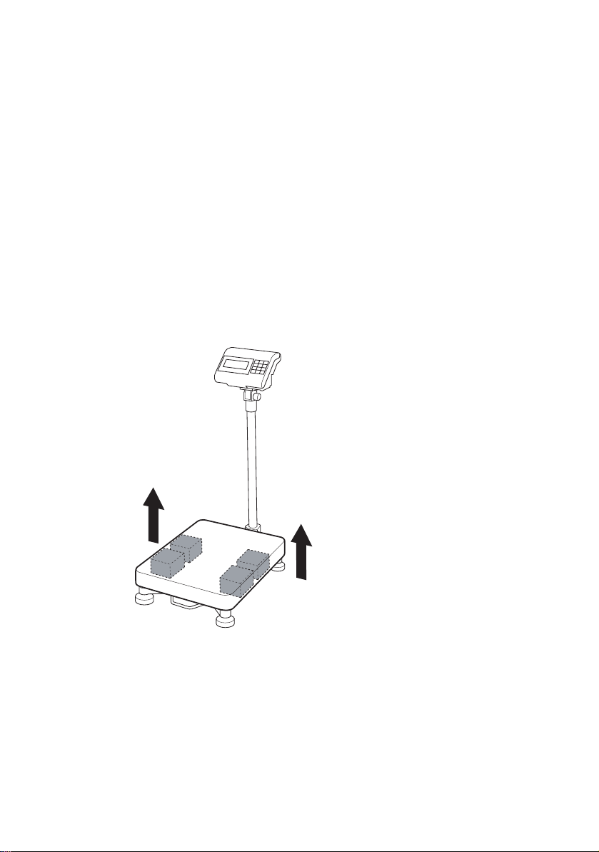
IMPORTANT
s
Before using the scale for the first time remove foam
packing from under the
shroud.
1. Lift off wei gh plate
2. Remove 4 x foam packaging block
3. Replace shroud
Page 3

©Salter Brecknell 2005. All rights reserved.
The information contai ned herein is the proper ty of Salter Brecknell Limited and is
supplied wi thout liability for errors or omissions. No part may be reproduced or used
except as authori
foregoing restriction on reproduction and use extend to all media in which the
zed by contract or other written permission. The copyright and t he
information may be embodied.
Page 4
Contents
3.0 Switching on the scale 13
page no.
1Warnings
1.1 Electr ic al in s t alla t ion 7
1.2 Risk of electric shock
1.3 Additional service precautions
1.4 Safe handling
1.5 ESD handling precautions
8
2 Introduction
2.1 Features 9
2.2 Keys
2.3 Error messages
10
3 Using the scale
3.1 Zeroing the scale 15
3.2 Data entry keys 1
3.3 Selecting weighing or counting 1
3.4 Using the backlight (option) 16
3.5 Switching between kgs and lbs 16
3.6 Sampling 1
3.7 Counting
3.8 Totali
3.9 Recalling totals 19
3.10 Cance
3.11 Check
3.11.1 Setting check-weighing limits
3.11.2 To set the lower limit
3.11.3 To set the higher limit
3.11.4 To set the alarm
18
zing 19
ling totals 20
weighing 21
7
7
8
12
5
6
7
S122 User / Service Instructions 4
Page 5

Contents
3.11.5 Limit indicators
3.12 Using tares 2
4 Installation/Maintenance
4.1 Connecting the column 28
4.2 Connecting the indicator 3
4.3 Opening the covers 3
4.4 RS232 PIN assignments 3
4.6 Replacing a load cell 33
5 Configuration Mo de
5.1 Entering configuration mode 34
5.1.1 Service mode keys 35
5.2 Configuration menu 36
5.2.1 F6 - exiting configuration mode 37
5.3 F0 - weight calibration 38
5.4 F1 - specification settings 40
5.4.1 Keyboard check 40
5.5 F2 - noise filter setting 44
5.6 F3 - zero display setting 45
5.7 F4 - check
5.8 F5 - print option 48
5.8.1 Printer outputs
5.8.2 RS232 interface specification
5.8.3 Data format
5.9 F6 - exiting configuration mode 55
5.10 F7 - displaying the internal count 55
5.11 F8 - setting the hold function 56
5.12 F9 - software lock 58
weighing function 46
5
0
1
2
5 S122 User / Service Instructions
Page 6

Contents
6
Wiring Diagrams
6.1 Power supply connections 58
6.2 Main board connections 59
6.3 Load cell connections 60
7 Parts L ists
7.1 Illustrated part lists 61
7.2 Additional parts 62
S122 User / Service Instructions 6
Page 7
1.1 Electrical installation 1 Warnings
1 Warnings
1.1 Electrical installation
The power cord must be connect ed to a su pp ly outlet with a
protective e arth
outlet must provide over current protection of an appropriate
rating.
Pluggable equipment must be installed near an easily
accessible socket outlet. Permanently connected equipment
must have a re adily a cce ssi b le d isc on nect device
incorporated i n the fixe d w iring.
For your protection all (110V or 230 V ) equipment used
out of doors or in wet or damp conditions should be supplied
from a correctly fused source and protected by an approved
RCD to BS7071 or BS7288 or BS4293. IF IN DOUBT SEEK
ADVICE FROM A QUALIFIED ELECTRICIAN.
1.2 Risk of electric shock
ground. The electr ica l s upply at t he sock et
This eq uip men t i s power e d by AC v o ltag e wh ich pr esen ts
an electric shock ha zard.
Always completely disconnect the power supply:
● Before removing the scale covers
● Before performing any routine maintenance
● Before cleaning the scale
1.3 Additional service precautions
● When the covers are removed, do not apply power to the
unit unless specifically instructed to do in this handbook.
● When working on live equipment, exercise great care,
use insulated tools and test equipment, and do not work
alone.
7 S122 User / Service Instructions
Page 8
1 Warnings 1.4 Safe handling
● When testing or fault finding, exercise extreme care.
Ensure that any test equipment used is in good condition
and capable of with
● All tools used must have insulated handgrips. T est probes
standing the existing voltages.
and jumper leads must be in good condition with
adequate insulation. Test probes with claw ends and
jumper leads must not have insecure parts that may fail
during use.
1.4 Safe handling
When lifting, moving o r su p porting the scale, ta ke its
weight into consideration.
1.5 ESD handling precautions
When handling printed circuit boards and electronic
components, observe the following ESD handling
precautions:
● Wear an grouned antistatic wrist strap.
● Ensure that all electronic components/boards are stowed
appropriately, by use of conductive/antistatic work
surfaces and packaging.
8 S122 User / Service Instructions
Page 9

1 Features 2 Introduction
2 Introduction
2.1 Features
1. High performance A/D converter.
● 0.3µv/ se n s i tivity
● Sample speed 16 times / second
● Maximum resolution : 15000
● Non-l inearity 0.01 % FS
● -1 mv ~ +5 mv
● Used range -1 mv ~ +14 mv
● Load cell excitation power 5VDC ±5% 100mA.
2. Adjustable noise filter setting for the range of s tability
from 01 ~ 15.
3. Depending on the calibration division:
● Standard division (under 10000)
Capacity and weight must be calibrated.
● Hi gh precision division (over 10000 to 150000
divisions)
Linearity, capacity and weight must be calibrated.
4. Option with RS232 output .
5. Three opti ons for the HOLD function.
6. AC / DC po we r su ppl y.
7. LCD display.
8. Auto-power cut off to ensure performance stability.
Power is cut off au tomatically if the power is below the
low battery warn ing .
9. Built-in backlight.
S122 User / Service Instructions 9
Page 10

2 Introduction 2.2 Keys
ENTER
CLEAR ENTRY
COUNT
SAMPLE
CLEAR ENTRY
2.2 Keys
ZERO
Zero key. Remove any weight on the platform before
pressing the key.
Data ent ry key . Increm ents the valu e of the select ed
digit.
Displays the backlight option.
Data entry key. Go to the next d igit.
Resets all values o n th e c urren t disp lay to ze ro .
Selects units of measure.
Switch es between kgs and lbs.
10 S122 User / Service I nstructions
RECALL
Selects counting mode.
Sample key. Disp l ays the nu mb er of items in the
sample.
Totalize key. Displa ys th e cou nt n umb e r and total
weight each time y ou add a w eight to th e platform.
Remove the weight from the platform when finished.
Recall totals. Displays the count number and then
the total for a few seconds. To cancel totals press
while the count number or total is
displayed.
Page 11
2.2 Keys 2 Introduction
TARGET
TARE
RECALL
CLEAR ENTRY
Sets checkweighing limits and beep option when in
counting mode.
Tares off the displayed weight of a container.
Enables you to enter a tare value when no weight is
on the platform. To view a tare press
followed by the tare key. To cancel a tare remove the
container and press the tare key. To cancel a preset
tare press
while the ta re is dis played.
S122 User / Service I nstructions 11
Page 12
2.3 Error messages 2 Introduction
-
-
2.3 Error messages
E1 When the scale is switched on, the we i ght on the
platform is above or greater than the automatic zero
range (greater than 10% o f th e ca p acity o f the sca l e) .
Make sure that there is no weight on the platform. If the
error persists, re-calibrate the m ac hine.
E2 When the scale is switched on, the we i ght on the
platform is below or low er tha n the a utom a tic zer o
range (greater than 10% o f th e ca p acity o f the sca l e) .
Correct service set up procedure has not been
followed. Ensure calibration weight is applied and
removed exactl y i n accordance with in structions.
E3 Not used.
E4 The weight on the platform is unsteady.
E5 There is a problem with the load cell. Check the wiring
(see
page 60). If th e err or pers is ts , re pla ce t he l oad ce ll
(see page 33).
E6 The internal zero value is greater than 360,000. The
error may occur in calibration mo de.
E7 The internal zero value is less than 24 0,000. The error
may occur in cali br ation mo de .
E8 This m essage will only app ear for legal for trade scales.
If you are configuring the ca paci ty of the
number of divisions cannot exceed 10,000.
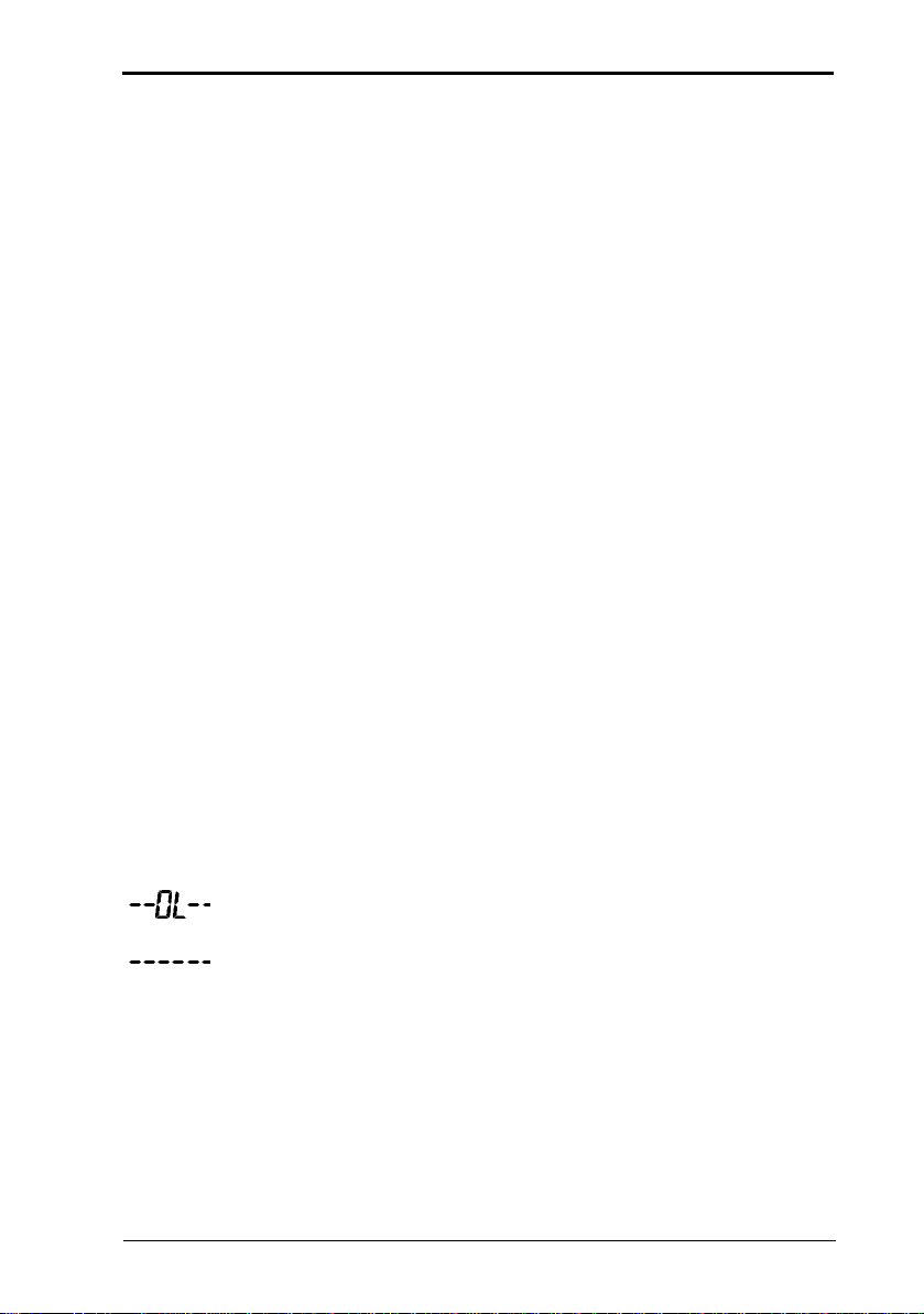
--OL-
-----
S122 User / Service I nstructions 12
The weight is greater th an the ca pa city o f the
Temporary error. Remove any weight from the platform,
switch off and then on ag a in. If this e rror p ersis ts,
contac t y o ur authori
zed servi c e agent.
scale, the
scale.
Page 13
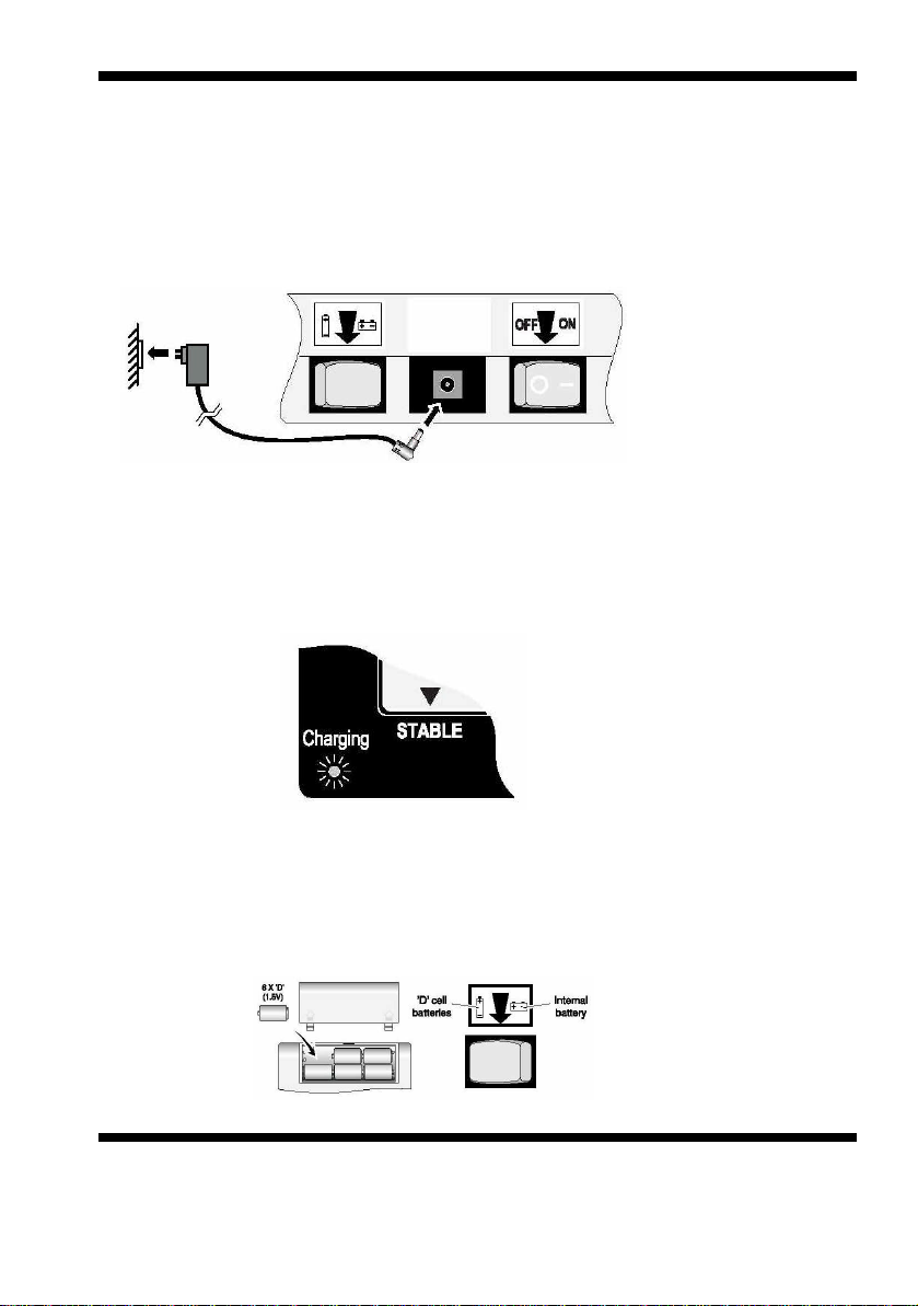
Connecting to the AC power supply.
Make sure that there is no weight on the platform before switching
on.
Plug the power supply lead into the scale.
Make sure that the battery switch is set to the internal battery.
When the scale is connected to the AC powersupply you will
see a red, yellow or green charging lamp depending on the
condition of the internal battery.
Using batteries
You can either use the internal rechargeable battery or use 6 size
’D’ cell batteries (alkaline batteries are recommended).
Use the battery switch to select either the internal battery or the ’D’
cells.
S122 User / Service Instructions
13
3.0 Switching on the scale.
Page 14
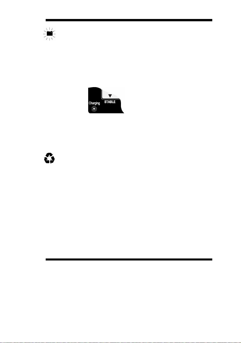
When
this symbol flashes, you should either replace the ‘D’ cell
batteries or recharge the internal battery.
Do not leave discharged batteries in the scale, asthey may leak
and cause serious damage. Do not store the machine with 'D' cell
batteries in the battery compartment.
Recharging the internal battery
While the machine is connected to the AC power supply and
internal battery is being recharged, the power supply light will turn
red, yellow, and then green.
To maintain the rechargeable battery in good condition, it should be
kept fully charged wherever possible. If the battery is to be stored,
the rechargeable battery should be fully charged before storage
and then recharged at 3 month intervals.
Disposing of the scale.
The scale contains a lead-acid battery. When disposing of the
machine, you should take it to an appropriate recycling facility.
S122 User / Service Instructions
14
Switching on the scale.
Page 15
3.1 Zeroing the scale 3 Using the scale
ENTER
CL
EAR ENTRY
3 Using the scale
Depending on the option of the machine, some functions
may not be available.
If the ▼ icon abov e th e STABLE legend flashes while you are
using the
unsteady.
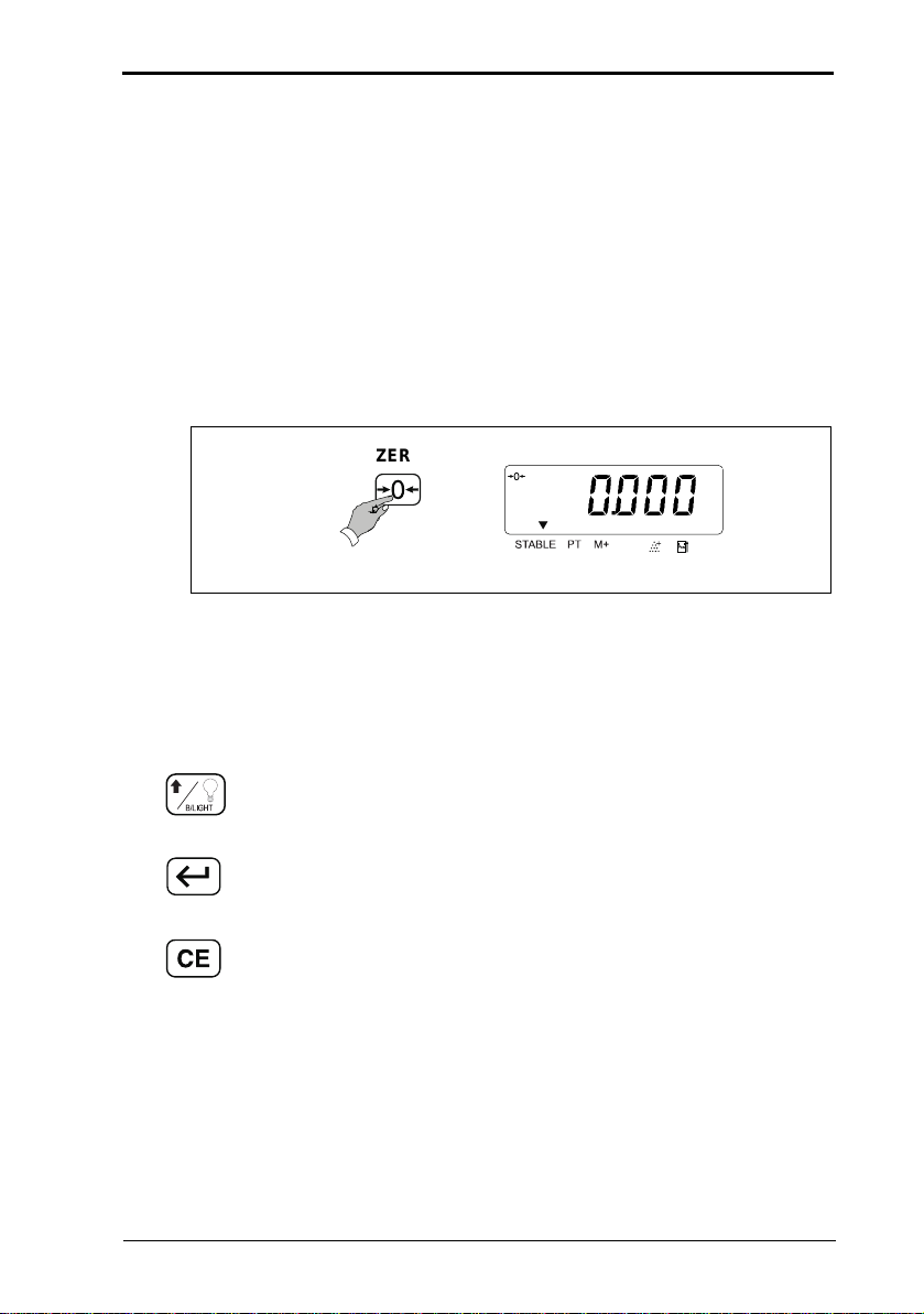
3.1 Zeroing the scale
Remove any weight from the platform.
scale, it means that the weight on the platform is
ZERO
3.2 Data entry keys
Whenever you nee d to enter va lues wh en se tting totalizi ng,
check
weig hi ng or pre-set tare s , use the fo llowing k e y s:
Increments the value of the selected digit.
Go to the next digit.
Restore all settings on the current display to zero.
.
0000
lb
S122 User / Service I nstructions 15
Page 16
3 Using the scale 3.3 Selecting weighing or counting
3.3 Selecting weighing or counting
COUNT
Weighing mode
Counting mode
If no s amp le size ha s be en set you wi ll b e p r ompte d to s ampl e
some items
.
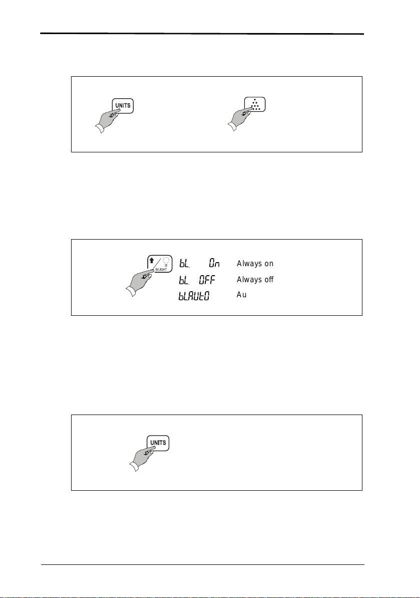
3.4 Using the backlight (option)
Each press of t he back l ig ht key sho ws :
bL. On
bL. OFF
bL.AUtO
Always on
Always off
Automati c back l ight
If set to automatic, the backlight comes on automatically when
the indicator is being used. A backlight may not be available
on some
scale.
3.5 Switching between lbs and kgs
16 S122 User / Service I nstructions
Page 17
3.6 Sampling 3 Using the scale
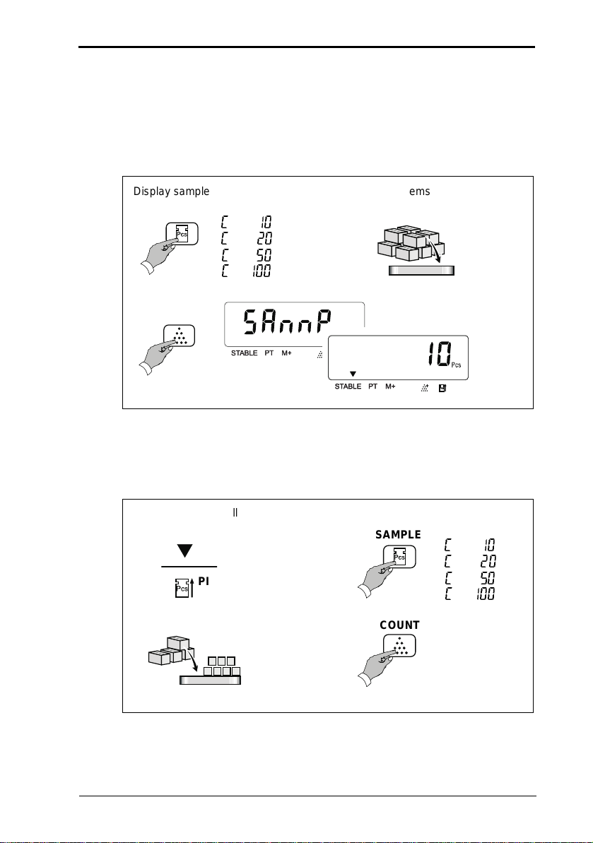
3.6 Sampling
When s e le c ting the number of i t e m s you wish t o use as a
sample remem ber th at the la rg er the samp l e size , the m o re
accurate the counting will be.
Disp la y sample num b e r
MPLE
SA
Place sample items on the platform
C 10
C 20
C 50
C 100
COUNT
If you see ▼ above the piece weight icon it means that the
unit weight of each item is too small and this may lead to an
inaccurate coun t.
Unit weight too small
SAMPLE
C 10
C 20
PIECE
WEIGHT
C 50
C 100
COUNT
S122 User / Service I nstructions 17
Page 18

3 Using the scale 3.7 Counting
If you see ▼ above the add to sample icon it means that the
weight of the sample is too small. Unless you increase the
weight of the sample the count may be inaccurate count. You
should select a greater number of samples and add these to
the sc al e.
Weight of sample too small
SAMPLE
C 10
C 20
ADD TO
SAMPLE
COUNT
C 50
C 100
3.7 Counting
Select either weighing or counting mode:
Weighing mode
COUNT
Count in g mo de
If you sel ect counti ng mode an d no sampl e size has be en s et
you will be prom pted to sa mple some i tems
18 S122 User / Service I nstructions
.
Page 19
3.8 Totalizing 3 Using the scale
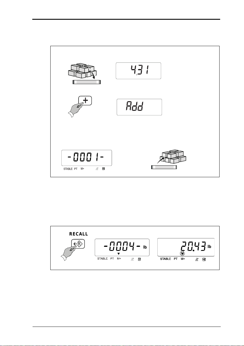
3.8 Totalizing
or each weight that you want to add:
F
lb
ADD
The count number and then the total weight will each be displayed
for a few seconds.
lb
Remove the w eigh t from the p latfor m wh en finish ed .
3.9 Recalling totals
The count number and then the total will each be displayed for
a few seconds before returning to the current display.
RECALL
- 0004- 2043
S122 User / Service I nstructions 19
lb
lb
Page 20

3 Using the scale 3.10 Canceling tota ls
3.10 Canceling tota ls
Press the clear key while the count number or total is displayed.
RECALL
CLEAR ENTRY
20 S122 User / Service I nstructions
Page 21

3.11 Checkweighing 3 Using the scale
3.11 Checkweighing
3.11.1 Setting check-weighing limits
Select either weighing or counting mode:
Weighing mode
COUNT
Count in g mo de
If you select counting mode and no sample size has been set
you will be prompted to sample some items
Disp la y sample num b e r
MPLE
SA
Place sample items on the platform
.
C 10
C 20
C 50
C 100
COUNT
S122 User / Service I nstructions 21
Page 22

3 Using the scale 3.11 Checkweighing
3.11.2 To set the lower limit
Example: 50 items
TARGET
0- - - -L
To move along the display:
ENTER
00000l
4 time s
To change the displayed value:
00005 l
5 times
To move along the display:
ENTER
00005 0
twice
To enter the lower limit:
ENTER
0- - H
22 S122 User / Service I nstructions
--
Page 23

.11 Checkweighing 3 Using the scale
3.11.3 To set the higher limit
Example: 1000 items
To move along the display:
ENTER
000- -H
twice
To chan ge the disp la ye d va lue:
000- -H
001000
4 times
To enter the hi gher limit:
ENTER
0- b
S122 User / Service I nstructions 234
Page 24

3 Using the scale 3.11 Checkweighing
3.11.4 To set the alarm
Example: beep when between targets
To move along the display:
ENTER
00b
To change the displayed value:
01b
To enter the alarm setting:
ENTER
0
The target b
eep can be:
00 = No target b
01 = B
eep when between targets
02 = B
eep when outside targets
eeps
3.11.5 Limit indicators
While using the scale you will see the following indicators to tell
you the status of the check-weighing:
LOW
OK
HIGH
24 S122 User / Service I nstructions
The weight/number of items is below the lower limit.
The weight/number of items is between the upper and lower
limit.
The weight/number of items is above the upper limit.
Page 25

Using tares
If you select counting mode and no sample size has been set you will be
prompted to sample some items.
Creating a tare
Viewing a tare
Canceling a tare
S122 User / Service Instructions
25
Page 26

Creating a preset tare
Example: 1lb
Reviewing a pre-set tare value
S122 User / Service Instructions
26
Page 27

Canceling a pre-set tare
S122 User / Service Instructions
27
Page 28

4.1 Connecting the column 4 Installation/Maintenance
4 Insta llation/Maintenance
4.1 Connecting the column
1. Lift the weigh p late off th e platfo rm an d rem ove th e
packin g m aterial .
2. Thread th e l oad cell cable A th roug h the c olumn .
3. Fasten the column to the platform using th e Allen ke y B
provided.
A
E
B
C
D
4. Remove the knob C from the brac ke t D and slide the
hinge apart slightly so that the plug can be threaded
through the cent
er of the bracket. Re assemb l e the
bracket.
S122 User / Service I nstructions 28
Page 29

4 Installation/Maintenance 4.1 Connecting the column
5. For legal for trade scales, make sure that the grounding
connector E is a ttached to the li p of the co l umn . If a
ferrite
bead is used it should hang on wire between connect or
A and bracket D.
6. Fasten the bracket to the colu mn. Ma ke su re that the
clamp is at the back of the
scale.
7. For legal for trade scales in US territory the scale must
be seal ed in the following mann er.
29 S122 User / Service I nstructions
Page 30

4.2 Connecting the indicator 4 Installation/Maintenance
A
4.2 Connecting the indicator
1. Slide the indicator onto the bracket until it clicks into
place.
2. Plug the conn e ctor from the platform into the ind icato r.
B
3. To adjust the angle of the indicator, loosen the knob A
and move the indicator until it clicks into the required
position.
4. To re move th e indi cator, disconnect, then pres s the
release catch B and carefully sl ide the ind icato r off the
platform.
S122 User / Service I nstructions 30
Page 31

4 Installation/Maintenance 4.3 Opening the covers
4.3 Opening the covers
You will need to remove the covers in order to set up RS232 PIN
connections
.
Electrostatic sensitive device
Obser ve all precaution s fo r handli n g e l e ctr ostatic
discharge sensitive devices.
1. If required, remove the indicator from the column.
2. Remove the battery cover.
3. Unscrew an d re m o ve the two cro ss-head screws.
4. Press in the bottom c over a t poi nt A to re leas e the c lips
on either side of the head. Th en ca re fully sl ide the
covers apart. You do not need to disconnect any of the
wiring.
5. To set up the PIN connections for RS232
communications, see section
6. Reassemble the covers replacing the screws.
7. Replace the indicator onto the column.
31 S122 User / Service I nstructions
4.4.
Page 32

4.4 RS232 PIN assignments 4 Installation/Maintenance
4.4 RS232 PIN assignments
The RS232 serial communications board allows the indicator
to send data to an e xte rnal de vice suc h a s a printer or
computer. The default baud rate is 2400. To change the
setting
communication board is s h own on page 59. .
J1 and J3 SHORT; J2 and J4 OPEN (default)
PIN 2 RXD
PIN 3 TXD
PIN 7 GND
Other pins are not used.
J2 and J4 SHORT; J1 and J3 OPEN
PIN 2 TXD
PIN 3 RXD
PIN 7 GND
Other pins are not used.
s see section
5.8. The wiring circuit of the RS232
S122 User / Service I nstructions 32
Page 33

4.6 Replacing a load cell 4 Installation/Maintenance
4.6 Replacing a load cell
1. Switch off and disconnect the scale from the AC
power supply.
2. Remove the shroud.
3. Discon nect a nd re mov e th e indi cator fr om th e c olumn.
4. Remove the knob from the bracket and slide the hinge
apart slightly so that the plug can be threaded through
the cent
5. Remo ve the bracket from the top of the co lum n .
6. For legal for trade scales, remove the grounded connection.
7. Remove the column.
8. Remove the two clips holding the cable to the platform.
9. Remove the four M8x 20mm socket head screws and
remove the
Note: these bolts will be very tight.
er of the bracket. Reass emb le th e bra cke t.
load bridge.
10. Turn the platform over and remove the four M8x 20mm
socket head screws hold ing the load cell to the platform.
Note: these bolts will be very tight.
11. Remove the load cell. Desolder the plug and retain.
To replac e the load cell, reverse the above procedure and
resolder the plug if necessary.
Torque settings for all bo lts to th e load c ell are: 440 pound-force.
S122 User / Service I nstructions 33
Page 34

5.1 Entering configuration mode 5 Configuration Mode
5 Configuration Mode
5.1 Entering configuration mode
In order to enter co nfigura tion mod e you mus t first se t the
configuration switch to the unlocked position. The switch is
located under the tamper proof s eal above the serial comm
socket on the right-hand side of the head.
Locked position Unloc ked position
unication
Set the configuration switch to
the unlocked position.
S122 User / Service I nstructions 34
Page 35

5 Configuration Mode 5.1 Entering configuration mode
u
s
Releas e the key.
CLEAR ENTRY
ENTER
ZERO
While the test is dis pla yed ,
p
ress and hold the key until yo
ee ...
ZERO
5.1.1 Service mode keys
The following keys are available in service mode:
TARE
Accept the entered values and go to the next section.
35 S122 User / Service I nstructions
Cancel all values for the current display.
Go to the next digit or field.
Increment the value of the current (usually flashing) digit.
Go to previous digit
Page 36

5.2 Configuration menu 5 Configuration Mode
TARE
5.2 Configur ation menu
The menu con sists o f functi ons F 0 to F 9. To go do w n the
functi ons pres s
press (F9 to F0).
F0
F1
F2
F3
F4
F5
F6
TARE
F7
F8
F9
(F0 to F9) . To go back up t he func tions
Function descrip tionFunction number
Weight calibration
Specification settings
Noise filter sett ing
Zero display setting
Check-weighing set tings
Print option
Exit configurat ion mode
Display internal val ue
HOLD function
Software lock
See page...
Page 38
Page
Page
Page
Page
Page
Page
Page
Page
Page
40
44
45
46
48
37
55
56
5
8
S122 User / Service I nstructions 36
Page 37

5 Configuration Mode 5.2 Configuration menu
ENTER
5.2.1 F6 - exiting configuration mode
Remember to se t the co nfigura ti on swi tch back to the locked
position.
TARE
or
Set the configuration switch to
the lock ed pos ition.
F6
.
0000
lb
37 S122 User / Service I nstructions
Page 38

5.3 F0 - weight calibration 5 Configuration Mode
ENTER
ENTER
5.3 F0 - weight calibration
● Ensure the hold function (F8) is set to hold 0.
Please remembe r .....
The c ali bration we ig ht must be over 0 weight or any weigh t
less than the fu ll capa city of th e mac hine .
2Ero
kg
0--.--C
Unit of calibration
To change the u nit of
calibration:
kg
lb
lb
kg
lb
0
--.--C
New uni t of calibration
T o change the flashing digit:
1--.--C
To go to the next digit:
ENTER
10-.--C
S122 User / Service I nstructions 38
Page 39

5 Configuration Mode 5.3 F0 - weight calibration
ENTER
ENTER
ENTER
Repeat t o en te r the ca libratio n
weight.
For example, to enter 30 lb:
twice
3 times
ENTER
kg
030.000
lb
3 times
kg
030.000
lb
Place the calibration weight on
the platform. Press the enter
key.
030.000
39 S122 User / Service I nstructions
Remove the calib ration
weight.
. lb
0000
kg
lb
Page 40

5.4 F1 - specification settings 5 Configuration Mode
ENTER
T
E
ZERO
See page 57
5.4 F1 - specification settings
● Ensure the hold function (F8) is set to hold 0.
5.4.1 Keyboard check
You can perform a keyboard check . If the correct code
appears when you press a key then you know that the key is
functioning correctly, see the table below. You cannot chec k
the
Function key Code Function key Code
PRESET TAR
key as it takes you to the ne xt ste p .
COUN
3E 27
3d 2b
37 1E
TARE
3b 1d
SAMPLE
2E 17
ADD
2d
RECALL
CLEAR ENTRY
TARGET
S122 User / Service I nstructions 40
Page 41

5 Configuration Mode 5.4 F1 - specification settings
ENTER
ENTER
I
FI
t
se
To check a key press the key:
If there is an error
you will see ...
17
273027
Internal count
E63027
E73027
nternal count
more than 360,000
SEt
Internal count
less than 240, 000
41 S122 User / Service I nstructions
Page 42

5.4 F1 - specification settings 5 Configuration Mode
ENTER
ENTER
Repeat until you have en tered
t
E
kg displayed
U00000
Unit options ar e:
digit 1 1= kg, 2= lb
digit 2 0= no 2nd unit
1= kg, 2= lb
digit 3 Must be set to 0
digit 4 0= kg display
1= g display
digit 5 0= lb display
1= lb, oz display
digit 6 Not used
T o change the flashing digit:
To go to the next digit:
Examples:
kg only 100xxx
lb only 200xxx
kg, lb units 120xxx
lb, kg units 210xxx
200000
lb primary unit
200000
secondary unit
S122 User / Service I nstructions 42
he required oiptions.
xample: 210010
21 = dual units lb and kg
digit 4 = kg displayed
digit 5 = lb, oz displayed
kg secondary unit
lb primary unit
not used
2100 0
Must be 0
lb, oz display ed
1
Page 43

5 Configuration Mode 5.4 F1 - specification settings
ZERO
ENTER
ZERO
ENTER
ZERO
kg
C000 00
lb
Press and to
enter the required capacity:
Full capacity + 9d
max lb w
wghtx2.24)
60kgx20g 006018
150kgx50g 015045
300kgx100g 003009
130lbx0.05l b 013045
330lbx0.10l b 003309
660lbx0.20l b 066010
Press and to
enter the weight settings:
digit 1 = divisions (1, 2, or 5)
digit 2 = decimal places
(1, 2, or 3)
digits 3 - 6 = 0
ight=(max kg
130lb ca pacity
013045
d00000
5300 00
Divisions=0.05lb
kg
lb
kg
lb
kg
lb
43 S122 User / Service I nstructions
Page 44

5.5 F2 - noise filter setting 5 Configuration Mode
twice
ENTER
ENTER
44
5.5 F2 - noise filter setting
The range of stability is from 01 to 15. E nte r a settin g
appropriate to the environment.
● The higher the value the quicker the machine reaches
stability bu t w eig hing is less ac c ur a t e.
● If the environment is unstable enter the value 15.
● If the environment is stable enter the value 05. This is the
default value.
● Ensure the hold function (F8) is set to hold 0.
F2
fiL 05
T o change the value:
fiL 06
F2
S122 User / Service I nstructions
Page 45

5 Configuration Mode 5.6 F3 - zero display setting
3 times
ENTER
ENTER
5.6 F3 - zero display setting
MUST BE SET TO 0 AT LEGAL FOR TRADE SCALES.
● If the load cell gives unstable readings set to 5 which is
the maximum.
● If the load cell gives stable readings set to 0 which is the
minimum.
● Ensure the hold function (F8) is set to hold 0.
F3
2Ero0
Zero display setting
0 =
default zero di sp lay readi n g wit hin
1 division
2 = zero di sp lay readi n g wit hin
2 divisions
T o change the value:
3 = zero display reading within
3 divisions
4 = zero display reading within
4 divisions
5 = zero display reading within
5 divisions
2Ero1
F3
45 S122 User / Service I nstructions
Page 46

5.7 F4 - checkweighing function 5 Configuration Mode
4 times
ENTER
ENTER
ENTER
low limit = 2lb
ENTER
46
5.7 F4 - checkweighing function
● Ensure the hold function (F8) is set to hold 0.
F4
kg
0--.--L
T o cancel the high/low limits and
alarm setting:
lb
5 times
ENTER
Press and
to enter the required low limit:
Low limit > 10 divi sions
S122 User / Service I nstructions
000.000
F4
002.000
0--.--H
kg
lb
kg
lb
kg
lb
Page 47

5 Configuration Mode 5.7 F4 - checkweighing function
ENTER
high li mit = 2.5lb
ENTER
ENTER
ENTER
Press and to
enter the required high limit:
High limit ≥ low limit
002.500
kg
lb
kg
0- b
lb
Check-weighing alarm digit 1
0 = Stable, b
1 = Stable, b
stable or not and LCD on
2 = Whether stable or no t,
b
LCD indication
Press and to
enter the required alarm setti ng:
eeps and LCD on
eeps whether
eeps and LCD on
LOW
OK HIGH
Check-weighing alarm digit 2
0 = No b
1 = OK (over low limits and under
high limits), b
2 = Under or equal to low limit
(must be ov er 10d) and
over or equal to high limit, b
eeps
eeps
eeps
01 = Beep between targets
01b
F4
kg
lb
47 S122 User / Service I nstructions
Page 48

5.8 F5 - print option 5 Configuration Mode
5 times
ENTER
ENTER
E
R
ENTER
E
R
48
5.8 F5 - print option
● Ensure the hold function (F8) is set to hold 0.
● To transmit to a computer short pins J1 and J3.
● To transmit to a serial printer short pins J2 and J4.
F5
Printer options are shown below:
0 Printing disabled.
1 Stable transmit for a PC.
2 Continuous printing for a PC.
3 Simple printing for serial printer. Press to print.
NTE
4 Full printing for ser ial printer. Press to print.
5 Stable printing (accumulation).
6 Full printing for EZ-2 printer. Press to print.
NTE
7 EZ-2 printer. Press to print.
S122 User / Service I nstructions
Page 49

5 Configuration Mode 5.8 F5 - print option
7 times
ENTER
ENTER
T o change the printer setting:
Exampl e EZ-2 printer
Default baud rate
Display the setting required by
the EZ-2 printer:
3 times
Baud rate options are:
1200, 2400, 4800, 9600
New baud rate
F5
49 S122 User / Service I nstructions
Page 50

5.8 F5 - print option 5 Configuration Mode
50
5.8.1 Printer outputs
The S122 can be connected to a computer running a suitable
application or a 40 column printer, see the typical outputs below.
rnP 1
PC stable transmit
When the weight is stable
press the key to tra ns m i t
each tran sa ct i on to th e PC .
ENTER
ENTERENTER
rnP 2
Continuous
transmission to PC
ST,NT,+ 1.000lb
ST,NT,+ 1.000lb
ST,NT,+ 2.002lb
ST,NT,+ 2.004lb
ST,NT,+ 0.000lb
ST,TR,+ 1.000lb
ST,NT,+ 0.990lb
ST,NT,+ 0.990lb
ST,NT,+ 1.000lb
ST,NT,+ 1.000lb
ST=Stable weight
NT=Gross weight
TR=Ne t weight in oper ation
TARE
UlbS,NT,+1.000lb
US,NT,+ 1.000lb
ST,NT,+ 1.000lb
ST,NT,+ 1.000lb
US,NT,+ 1.000lb
US,NT,+ 1.000lb
ST,NT,+ 0.890lb
ST,NT,+ 0.890lb
ST,NT,+ 1.000lb
ST,NT,+ 1.000lb
The weight is continuously transmitted to the PC.
S122 User / Service I nstructions
Page 51

5 Configuration Mode 5.8 F5 - print option
rnP 3
Simple mode for serial printer
To transmit each transaction to the
printer:
ENTER
or
To transmit the total to
the printer:
ENTERENTER
ADD
S/N WT/lb
_ _ _ _ _ _ _ _
001 2.000
002 1.000
_ _ _ _ _ _ _ _
0002 3.000
rnP 4
Full mode for serial printer
To transmit each transa ction
to the printer:
ENTER
ADD
or
TICKET NO.0001
G 1.000lb
T 0.000lb
N 1 .0 00l b
TICKET NO.0002
G 2.000lb
T 0.000lb
N 2 .0 00l b
To transmit the total to
the printer:
ENTERENTER
TICKET NO.0003
G 2.000lb
T 1.000lb
N 2 .0 00l b
TOTAL NUMBER
OF TICKETS 0003
TOTAL
NET 4.000lb
51 S122 User / Service I nstructions
Page 52

5.8 F5 - print option 5 Configuration Mode
52
rnP 5
Stable printing (accumulation)
To transmit each transaction
to the printer:
ENTER
ADD
or
To transmit the total to
the printer:
ENTERENTER
rnP 6
Full mode for EZ-2 printer
To tran smi t eac h tr ans ac ti on t o t he
printer:
ENTER
ADD
or
To transmit the total to
the printer:
ENTERENTER
S/N WT/lb
_ _ _ _ _ _ _ _
001 1.000
002 2.000
003 2.000
004 2.000
005 2.000
_ _ _ _ _ _ _ _
005 9.000
TICKET NO. 0001
G 1.000lb
T 0.000lb
10152 1.000lb
03
TICKET NO. 0002
G 1.000lb
T 0.000lb
10152 1.000lb
03
TICKET NO. 0003
G 2.000lb
T 0.000lb
N11 2.000lb
03
S122 User / Service I nstructions
Page 53

5 Configuration Mode 5.8 F5 - print option
rnP 7
Stable tra nsmit to EZ-2 printer
To transm it eac h t ransactio n t o
the printer:
151123+ 1.000lb
151123+ 1.000lb
151123+ 0.000lb
151123+ 0.000lb
151123+ 2.000lb
151123+ 2.000lb
5.8.2 RS232 interface specification
I. Mode : EIA-RS023 2 C ’s UART signal
II. Format:
Baud rate Can select
1200, 2400, 4800, 9600 BPS
Data bit 8 bits
Parity bit None
Stop bit 1 bit
Code ASCII
Start bit
53 S122 User / Service I nstructions
Data bits
Stop bit
Page 54

5.8 F5 - print option 5 Configuration Mode
54
5.8.3 Data format
Data format for stable and continuous transmission.
Head 1
(2 bytes)
OL Overload, under load
ST Display is stable NT Net mode
US Display is unstable GS Gross mode
Head 2
(2 bytes)
Data (8 bytes)
2D (HEX)= "-" (minus)
2E (HEX)= "." (decima l po int)
Unit (2 bytes)
kg =6B (HEX) ; 67 (HE X)
lb =6C (HEX) ; 62 (HEX)
Example 1: +0.876k g stable weight and net value
Example 2: -1.568lb unstable weight and net value
S122 User / Service I nstructions
Page 55

5 Configuration Mode 5.9 F6 - exiting configuration mode
7 times
ENTER
ENTER
5.9 F6 - exiting configuration mode
See page 37 .
5.10 F7 - displaying the internal count
● Ensure the hold function (F8) is set to hold 0.
F7
273027
Internal count
F7
55 S122 User / Service I nstructions
Page 56

5.11 F8 - setting the hold function 5 Configuration Mode
ENTER
ENTER
ENTER
56
5.11 F8 - setting the hold function
You can set up th e h old functi on so pressi n g the key
prints the displayed valu e. Yo u m ust a lso s et u p the c or rect
transmit baud rate for th e rec eivi ng de vice .
Hold 0
No hold function.
Hold 1
When the weight is continuously changing the scale
automatically holds the maximum value.
002.500
Pres s any key o ther than to clear the hold.
Hold 2
When the wei gh t beco m es stabl e the scale automatically
holds the displayed value. Press any key other than
clear the hold.
Hold 3
When the wei gh t beco m es stabl e the scale automatically
holds the dis pl ay ed va lu e. Th e hol d c lea rs wh en the w ei ght i s
removed and th e ma ch ine r etu rns to zer o w eight.
lb
to
S122 User / Service I nstructions
Page 57

5 Configuration Mode 5.11 F8 - setting the hold function
ENTER
ENTER
F8
8 times
kg
ho1d-0
T o change the hold setting:
ho1d-3
lb
kg
lb
F8
57 S122 User / Service I nstructions
Page 58

6.1 Power supply connections 6 Wiring Diagrams
'D' cell batteries
r
T o mainboard
58
6 Wiring Diagrams
Electrostatic se n si tive dev ice
Observe all precautions for handling electrostatic
discharge sensitive devices.
6.1 Power supply conn ections
Battery
selector
switch
AC Power
in socket
On/off
Switch
Green
Orange
Blue
Red
Black
Yellow
Brown
Note: All connections are soldered.
Internal
rechargeable
battery
Red
= 0.1µFCapacito
S122 User / Service I nstructions
Page 59

Wiring Diagrams
59
p
i
n
6.2
6.2
6.2 Main board connections
Main board connections
S122 User / Service I nstructions
Page 60

6.3 Load cell connections 6.3 Wiring Diagrams
60
Shield
6.3 Load cell connections
S122 User / Service I nstructions
Page 61

7.1 Illustrated part lists 7.1 Parts Lists
61
14.5x20.5 in
17.3x23.6 in
14.5x20.5 in
17.3x23.6 in
14.5x20.5 in
17.3x23.6 in
Shroud
Load Bridge
7Parts Lists
7.1 Illustrated part lists
e
Ins
t
c
i
v
r
u
r
e
s
/
User
76103-986
c
t
i
ons
S122 User / Service I nstructions
Page 62

7.2 Parts Lists 7.2 Additional parts
62
1140780136
Power adaptor - USA 110
7.2 Additional parts
Description Part number
Sealing screw kit SER/L120/0002
Ground spring SER/L120/0003
On/Off switch 1111001111
Battery select o r switc h 1111001221
Load cell connector - male 5-way 1240001051
Load cell connector - male 6-way 1240001061
Load cell connector - female - 5-way 12400 01050
Load cell connector - female - 6-way (approved) 1240001060
Keyboard KB4T1A 0A2000
Keyboard overlay 1220355122
S122 User / Service I nstructions
Page 63

The address of your Salter Bre cknell center is
This document contains a general guide only of the product and shall not form part of any contract unless specifically agreed by Salter Brecknell Weighing in writing
in each case on the Order Acknowledgement. The specification of the products described herein may vary from time to time and may be altered without notice.
USA
Salter Brecknell Weighing Products USA
1000 Armstrong Drive
Fairmont
MN 56031
Toll Free:
800-637-0529
Phone:
507-238-8702
Fax:
507-238-8271
Email:
sales@salterbrecknell.com
Web site:
www.salterbrecknell.com
UK and Europe
Web site:
Salter Brecknell Weighing
Tel:
+44 (0) 870 444 6132
Fax:
Email:
+44 (0) 870 010 2241
sales@salterbrecknell.co.uk
www.averyweigh-tronix.com
P.O. Box 9533
Smethwick
West Midlands
B66 2TE
 Loading...