

Page 1
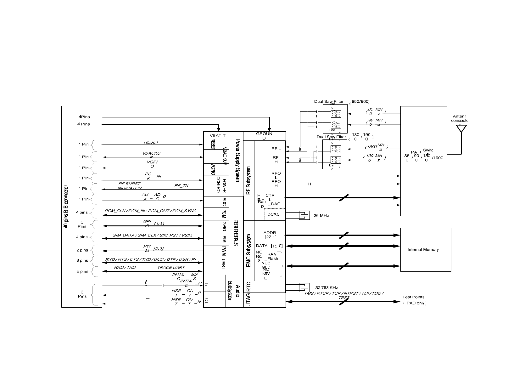
1. Block diagram
Operational Description of HiLoV2 module
Page 2

2. Functional description
2.1 Power supply system
The power supply system includes: VBAT, VGPIO, VBACKUP, Reset and Power
control (POK_IN signal, RF burst indicator signal).
The VBAT is the power supply for the module. Its range is from 3.2V to 4.5V.
The VGPIO is the power supply output from the module. It is supplied for external
circuits and its rated value is 2.8V.
The VBACKUP is the power supply of backup battery. It should be connected to a
backup battery. If no backup battery is provided, a 10uF capacitor should be
connected between VBACKUP and GND.
The reset signal is used to reset the whole module as the requirement.
The POK_IN signal is used for powering up the module. When this signal is pulled
down for a few seconds, the module will be powered up.
The RF burst indicator signal is used for indicating the RF burst. When the RF burst
comes, it will be in high voltage level. Otherwise, it will be in low voltage leve.
2.2 RF subsystem
The RF subsystem includes: internal RF circuit, one antenna connector and two
antenna pads.
The internal RF circuit is inside the module and works for RF communication.
The antenna connector is used for the connection between the module and external
antenna.
The two antenna pads are also used for the connection between the module and
external antenna.
The antenna connector and antenna pads can not be used at the same time.
2.3 EMC subsystem
The EMC subsystem is inside the module and used for reading and writing system
data.
Page 3

2.4 RTC
There is a RTC crystal inside the module. It is used for real time counting.
2.5 JTAG
There are 9 JTAG pads in the module. They are for JTAG debugging and reserved
for Sagemcom.
2.6 Peripherals
The peripherals include: ADC, PCM, GPIO, SIM, PWM and two UARTs.
The ADC allows external sensor analog input to the module.
The PCM is the digital audio interface which can be used for digital audio data
communication with host CPU.
The GPIOs are used for controlling external circuits. There are 3 GPIOs in the
module.
The SIM interface is used for SIM card connection. 3V or 1.8V SIM card can be
connected to the module through this interface.
There are two PWMs in the module. PWM0 is dc PWMs and used for external LED
driving. PWM2 is a buzzer PWM and used for driving buzzer.
A V24 full UART is provided in the module. With this UART port, the module can
communicate with other processors.
A two-wire UART is reserved for Sagemcom. It is for debugging.
2.7 Audio subsystem
A single-end audio input signal and a pair of differential audio output signals are
provided in the module. They are used for connecting microphone and receiver.
 Loading...