


F@ST 3686 V2.2
User Manual
1. Introduction
This F@ST 3686 Cable Gateway is an Embedded Media Terminal Adapter (EMTA) which is CableLabs DOCSIS 3.0 and PacketCable 1.5 compliant. It provides high-speed Internet access as well as cost-effective, toll-quality telephone voice and fax/modem services over residential, commercial, and education subscribers on public and private networks via an existing CATV infrastructure. F@ST 3686 offers high-speed LAN connec tivity with 4 Gigabit Ethernet ports and one integrated Wireless LAN access point compatible with IEEE 802.11a/b/g/n. The Wireless access point is operating on 2.4GHz band.
Package Contents
F@S T3284u Gateway |
x1 |
Ethernet Cable (RJ45) |
x1 |
Phone Cable (RJ11) |
x1 |
Quick Start Guide |
x1 |
Power Supply Unit |
x1 |
2. Hardware Connection
1 |
2 |
3 |
4 |
5 |
6 |
1 |
RJ-11 Telephone port lines 1 and 2 |
|
|
||||||
|
|
|
|
|
|
2 |
Ethernet 10/100/1000 BaseT RJ-45 connector |
|
|
|
|
|
|
3 |
Restore To Factory Defaults button |
|
|
|
|
|
|
4 |
RF coaxial F-connector |
|
|
|
|
|
|
5 |
Power plug |
|
|
|
|
|
|
6 |
Power switch ON/OFF |
Page 1
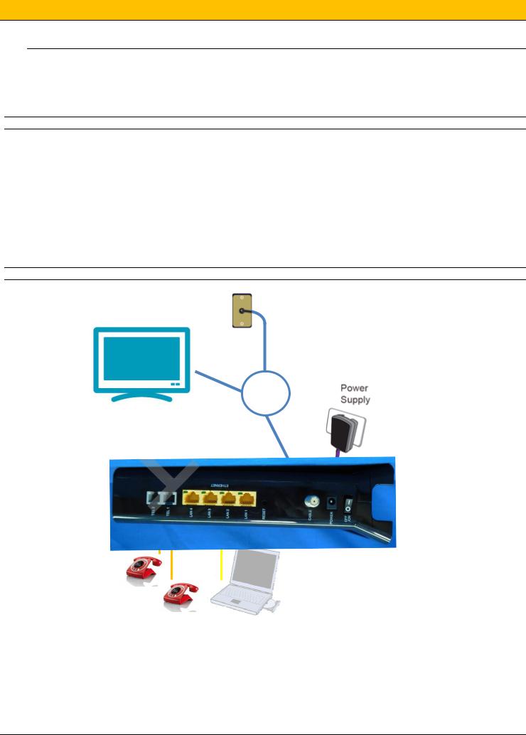
3. Connecting the F@ST3284 Gateway to Your Computer
Installation Procedure for Ethernet Interface
Follow the steps below for proper installation:
1.Make sure your computer meets the system requirements.
2.Connect a coaxial cable to the wall plug
3.Connect a coaxial cable to the CABLE connector on the F@ST3686 and screw it at the bottom manually (do not force).
Note: To speed up the registration process of F@ST3686 , the coaxial cable should be connected to the gateway prior to the power connector.
4.Connect the RJ45 Ethernet cable to the ETHERNET connector on the gateway, connect the other end with the 10/100/1000BaseT Ethernet port on your computer.
5.Plug the RJ11 telephone cord(s) to the TEL 1 or TEL2 connector (s) of the cable modem. (Plug the RJ11 telephone cord(s) to the PSTN connector on the modem, connect to the PSTN service provider. This step is for EMTA with PSTN model only.)
6.Plug the power supply unit into the POWER connector of the modem.
7.Plug the other end of the power supply unit into a power outlet.
8.Power ON the F@ST3686 by pressing the ON/OFF button on the rear panel of the F@ST3686.
9.The cable gateway will look for the proper cable modem signal in the Cable Television network and process the initial registration. The cable gateway is ready for data transfer after the LED “INTERNET” is in solid white. The gateway is ready to make a phone call after the LED “Tel1” or “Tel2” is in solid white.
Note: The RESET button at the rear panel is for maintenance purpose only.
Cable splitter
The screen of the coaxial cable is intended to be connected to earth in the building installation
Page 2

4. Wireless Connection
Step 1 |
Step 3 |
|
•Under the gateway, on the |
|
label, note the reference of |
|
SSID and WPA wireless |
|
password. |
Step 2 |
Step 4 |
•Click on “Start” then on: o Network Connection
o Wireless network connection
oIn this new Window, search for the SSID value and select it by double clicking on it.
oThe computer asks for a password. It is the WPA wireless password.
oOnce the password entered twice, press “Connection” button. WiFi Configuration is finished.
5. F@ST3284u Personalization
Step 1 |
Step 2 |
|
• Open an Internet session and type the following address: |
•Connect by typing: |
|
http://192.168.1.1 |
||
Username: admin |
||
|
||
|
Password: admin |
|
|
•Click on “OK” button |
|
|
|
|
Step 3 |
Status |
|
|
To know the state of your connection of your F@ST3284u |
|
|
Basic |
|
|
To perform the basic configuration of your F@ST3284u |
|
|
Advanced |
|
|
To perform advanced routing configuration of your F@ST3284u |
|
|
Firewall |
|
|
To protect your LAN equipment from malicious attacks |
|
|
Parental Control |
|
|
To safely restrict and control the Internet usage to your family |
|
|
Wireless |
|
|
To configure the WiFi network of your F@ST3284u |
|
|
MTA |
|
|
To check the telephony status of your F@ST3284u |
|
|
|
Page 3
 Loading...