

Page 1
Vending Machine
UK
WARNING: This instruction manual is intended exclusively for specialized personnel.
USE AND MAINTENANCE
Page 2
English
2
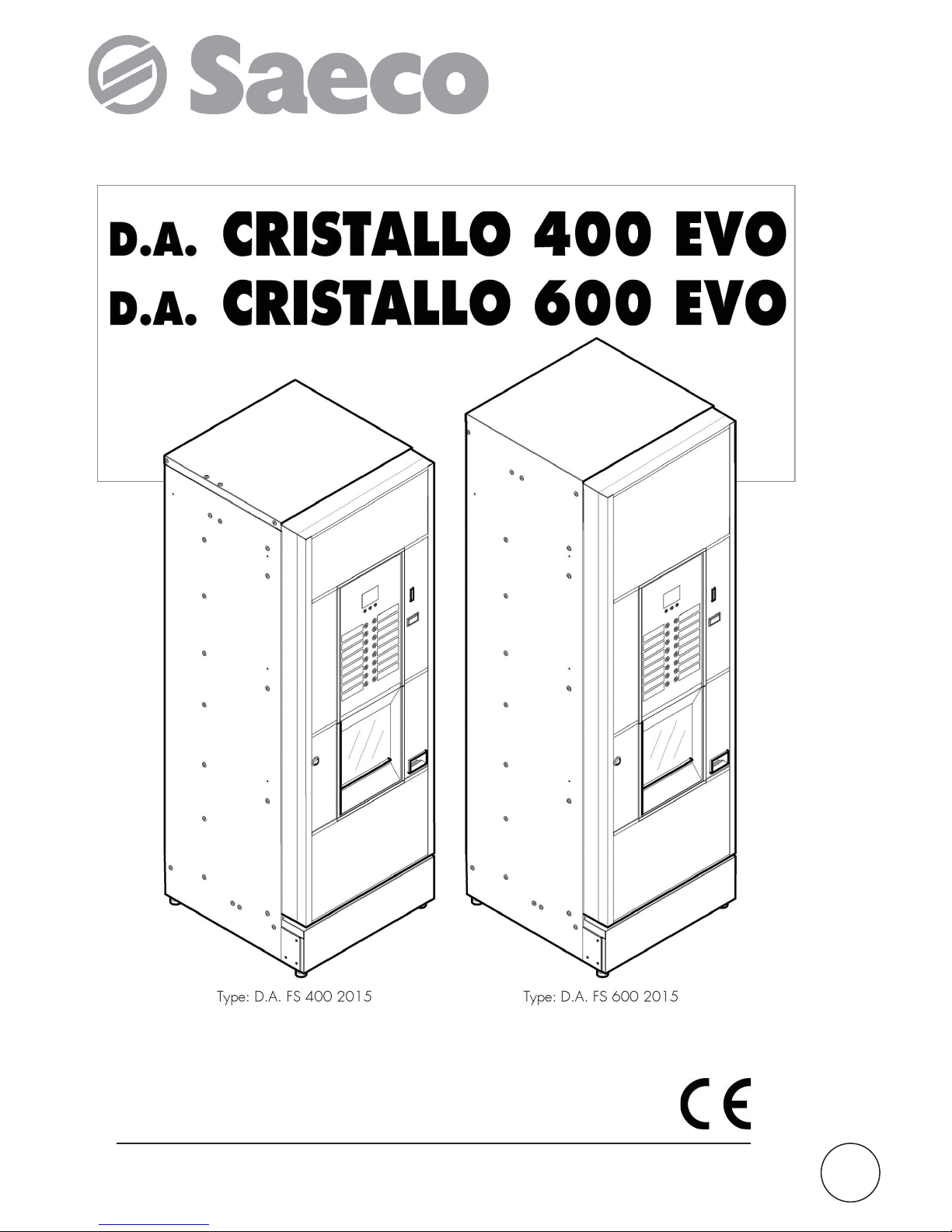
MAIN PARTS
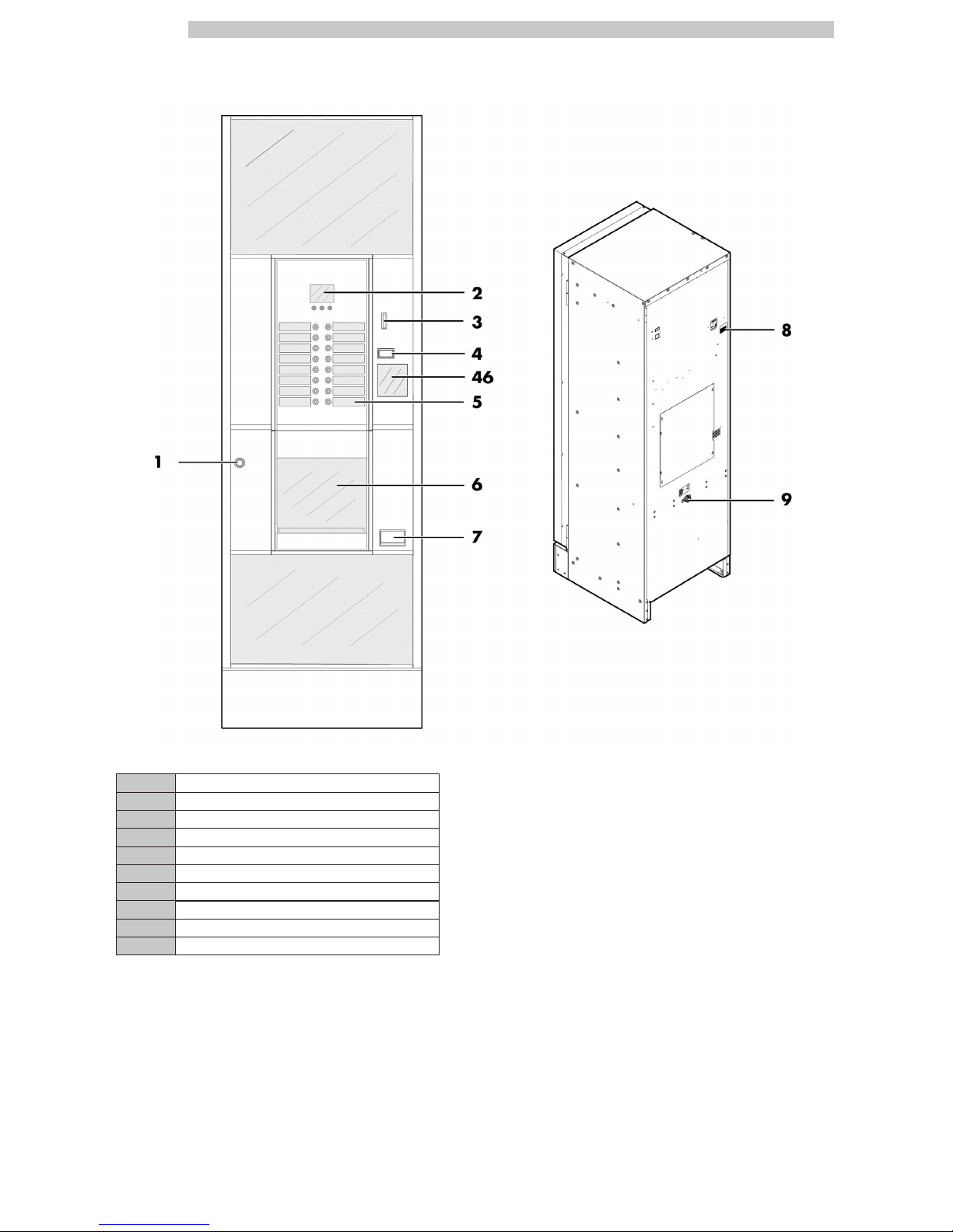
CRISTALLO 400 EVO MAIN PARTS
1 Door lock
2 Display
3 Coin slot
4 Coin return button
5 Product keypad
6 Dispensing outlet door
7 Coin return slot
8 Power cord socket
9 Water connection coupling
46 Instruction plate
Page 3
English
3
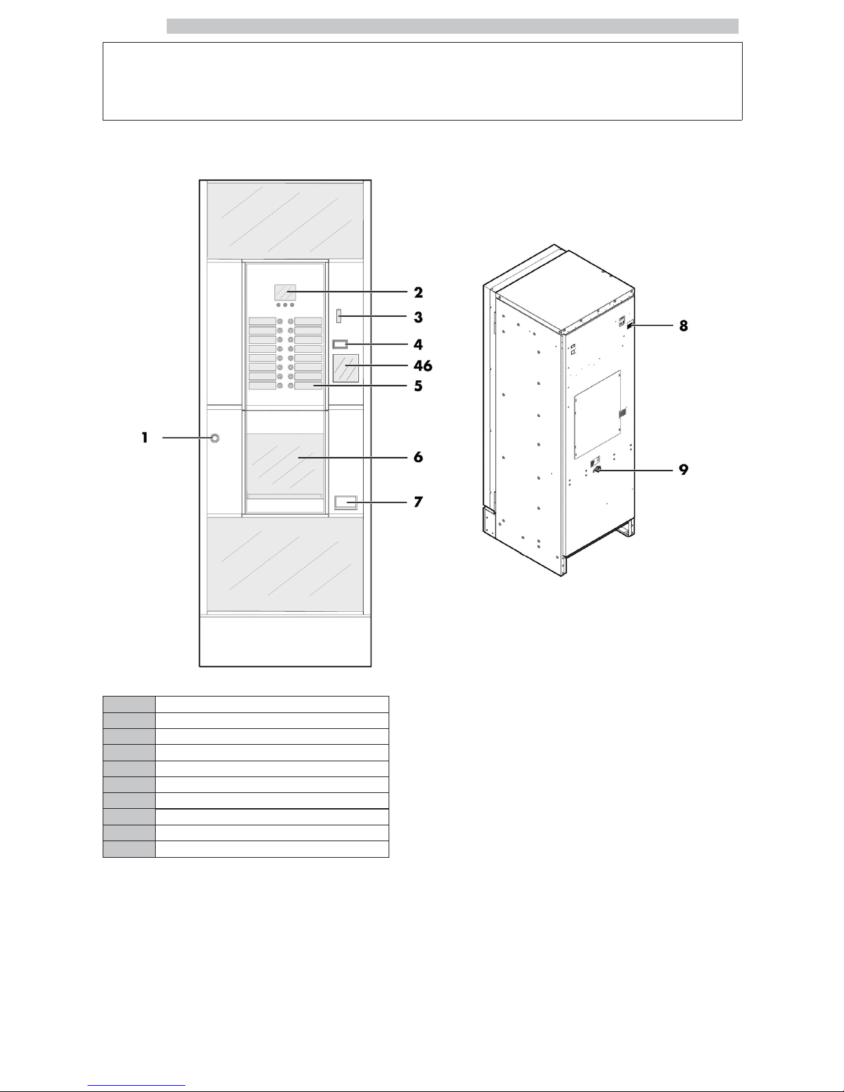
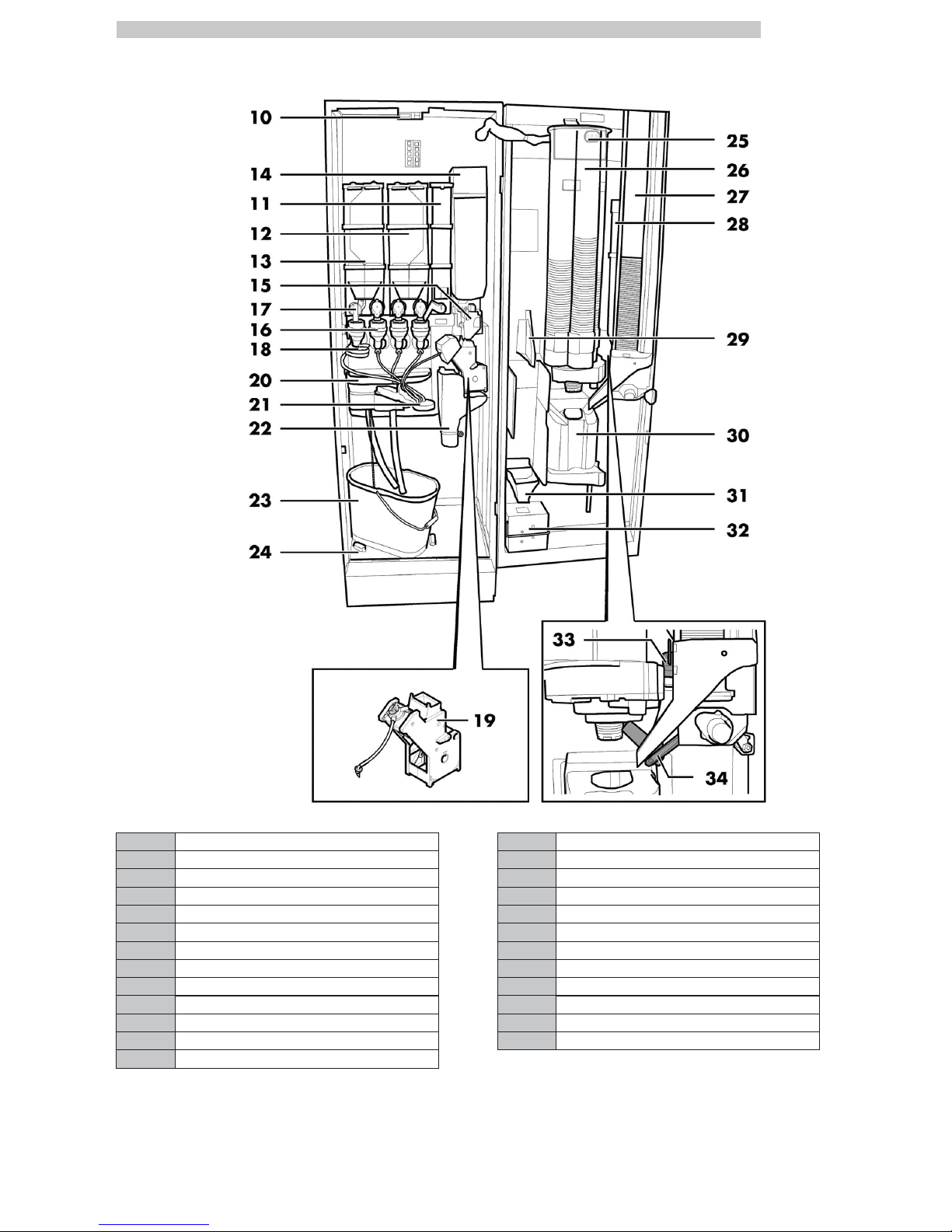
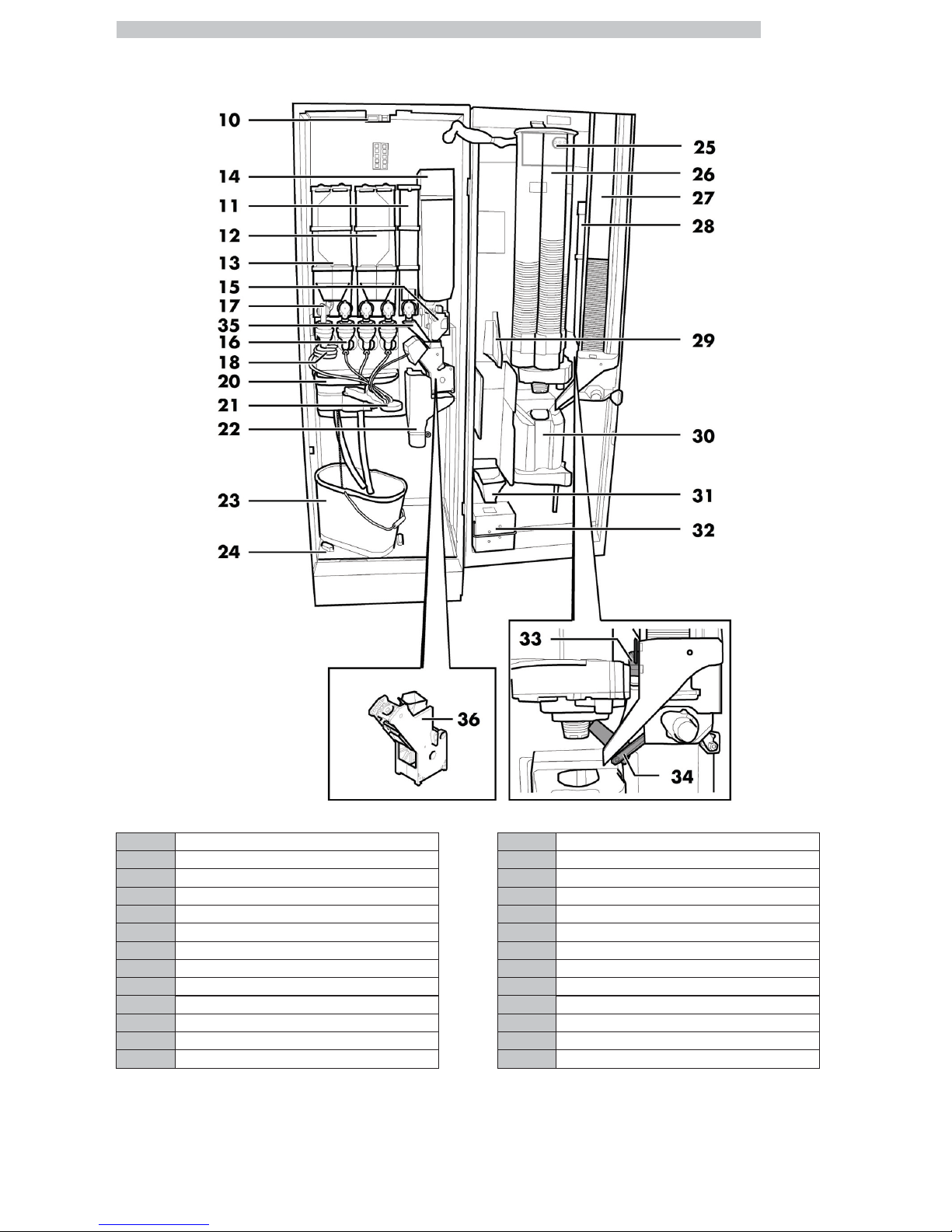
CRISTALLO 400 EVO Main parts - Espresso version with double containers
10 Safety switch 23 Fluid discharge tank
11 Container 5 (instant products) 24 Collecting tray
12 Container 3/4 (instant products) 25 CPU card
13 Container 1/2 (instant products) 26 Cup dispenser
14 Coffee bean container 27 Stirrer dispenser
15 Coffee grinder 28 Sugar container
16 Mixer 29 Change-giving coiner support
17 Instants opening 30 Dispensing outlet
18 Spiral mixer 31 Coin return duct
19 Gran Gusto Brew Group 32 Coin box set
20 Drip Tray 33 Sugar opening
21 Dispensing arm 34 Chute
22 Coffee ground channel 41 Air break device
Page 4
English
4
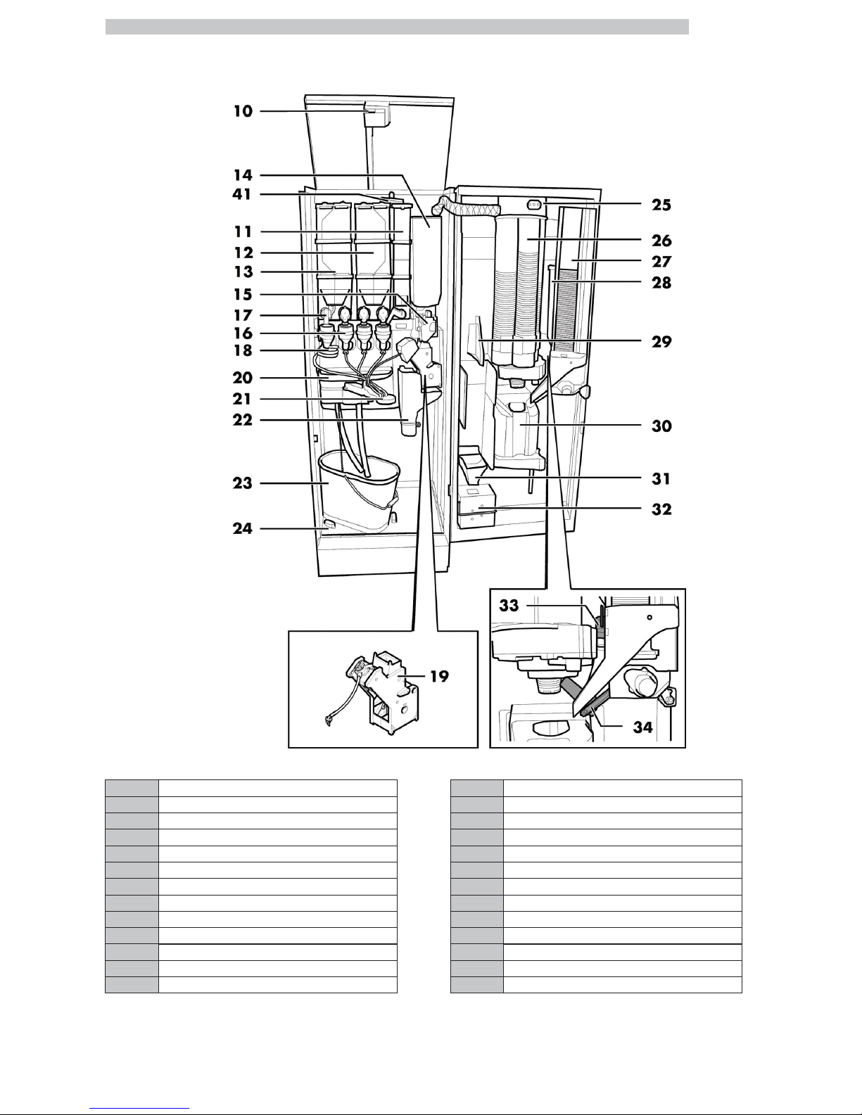
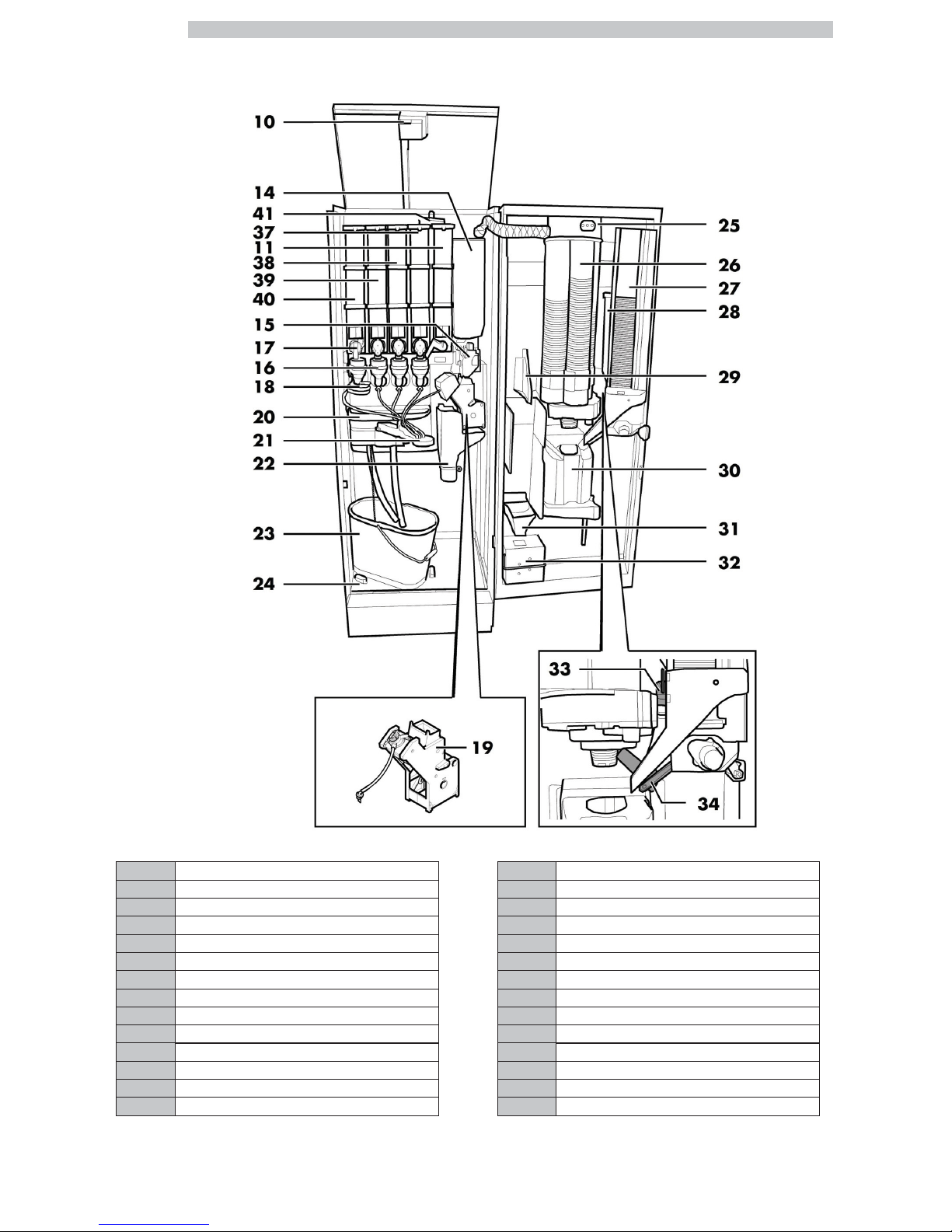
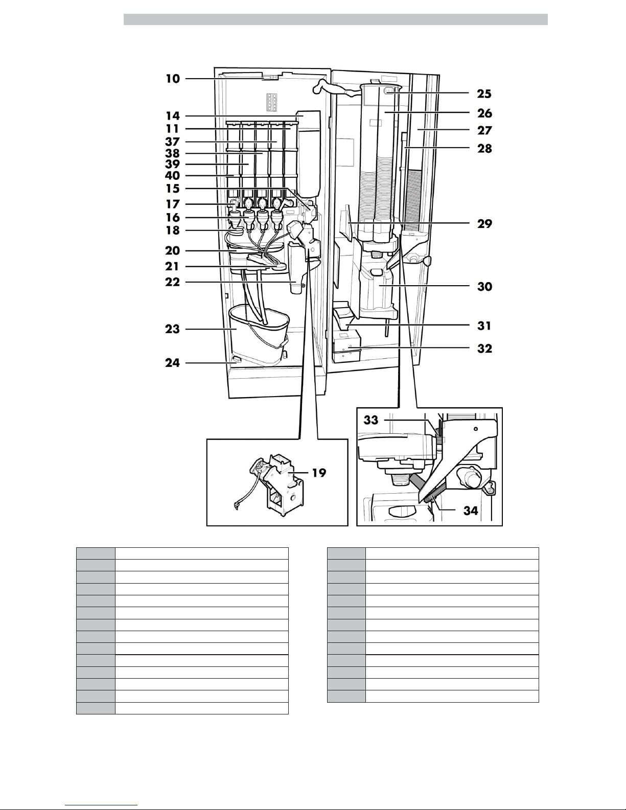
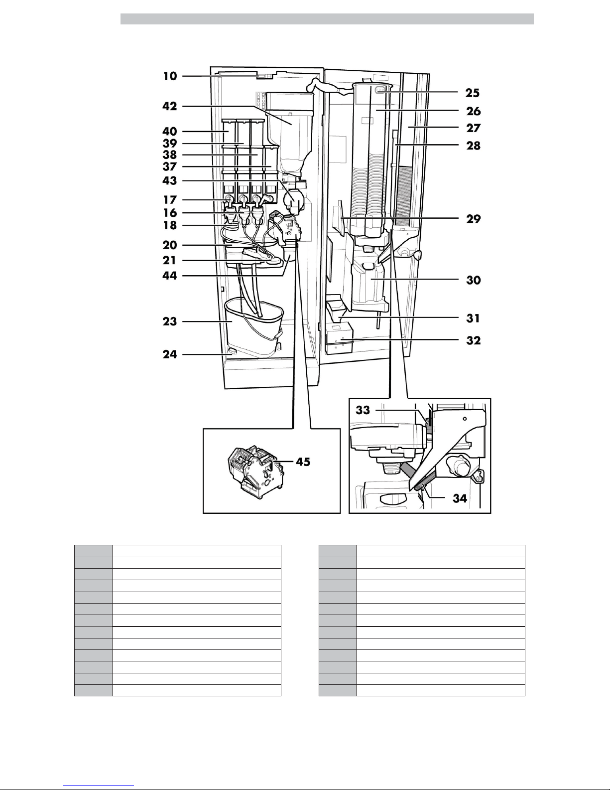
CRISTALLO 400 EVO Main parts - Espresso version with single containers
10 Safety switch 26 Cup dispenser
11 Container 5 (instant products) 27 Stirrer dispenser
14 Coffee bean container 28 Sugar container
15 Coffee grinder 29 Change-giving coiner support
16 Mixer 30 Dispensing outlet
17 Instants opening 31 Coin return duct
18 Spiral mixer 32 Coin box set
19 Gran Gusto Brew Group 33 Sugar opening
20 Drip Tray 34 Chute
21 Dispensing arm 37 Container 4 (instant products)
22 Coffee ground channel 38 Container 3 (instant products)
23 Fluid discharge tank 39 Container 2 (instant products)
24 Collecting tray 40 Container 1 (instant products)
25 CPU card 41 Air break device
Page 5
English
5
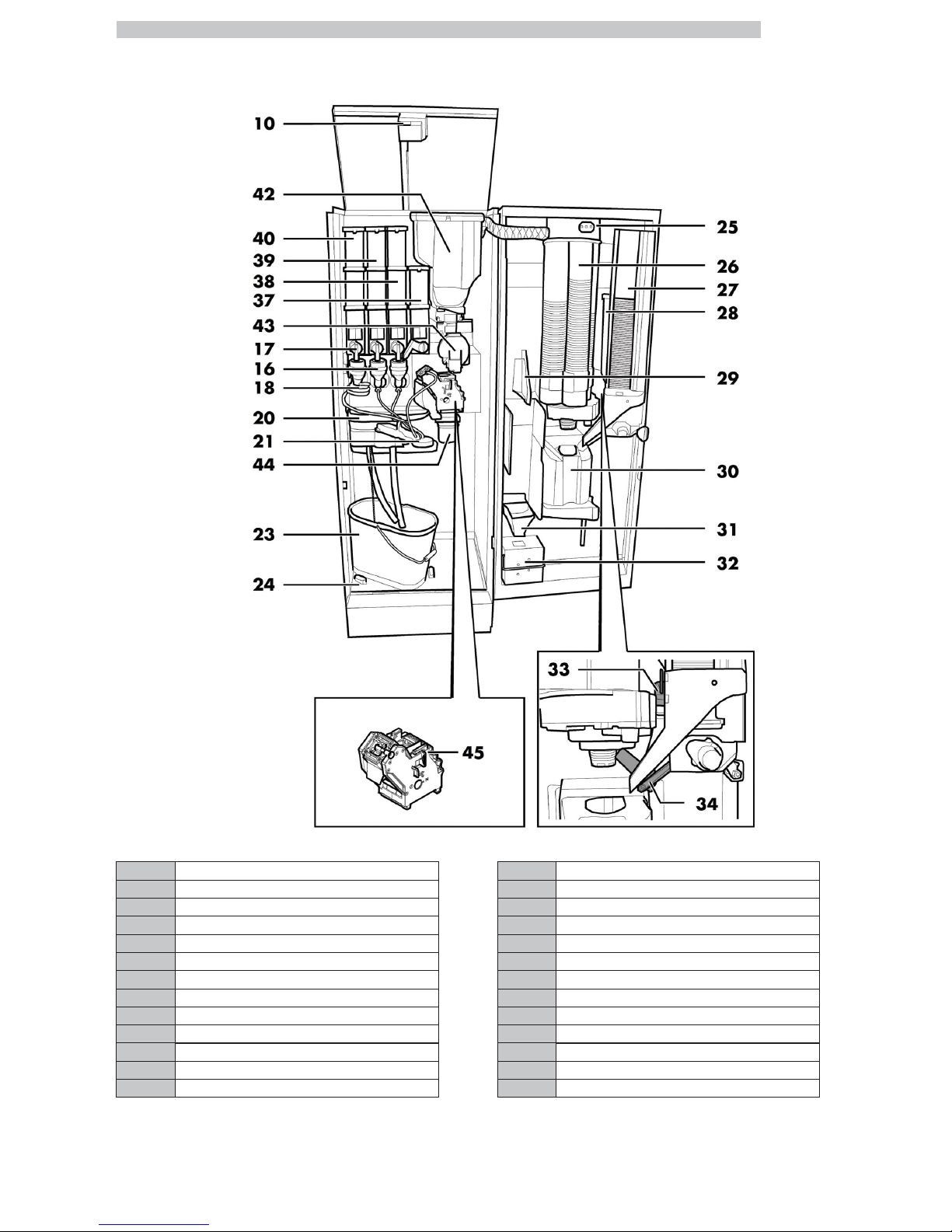
CRISTALLO 400 EVO MAIN PARTS CAPSULES
10 Safety switch 30 Dispensing outlet
16 Mixer 31 Coin return duct
17 Instants opening 32 Coin box set
18 Spiral mixer 33 Sugar opening
20 Drip Tray 34 Chute
21 Dispensing arm 37 Container 4 (instant products)
23 Fluid discharge tank 38 Container 3 (instant products)
24 Collecting tray 39 Container 2 (instant products)
25 CPU card 40 Container 1 (instant products)
26 Cup dispenser 42 Coffee capsule hopper
27 Stirrer dispenser 43 Capsule conveyor
28 Sugar container 44 Used capsule chute
29 Change-giving coiner support 45 Capsule coffee Brew Group
Page 6
English
6
CRISTALLO 600 EVO MAIN PARTS
1 Door lock
2 Display
3 Coin slot
4 Coin return button
5 Product keypad
6 Dispensing outlet door
7 Coin return slot
8 Power cord socket
9 Water connection coupling
46 Instruction plate
Page 7
English
7
CRISTALLO 600 EVO Main parts - Espresso version with double containers
10 Safety switch 23 Fluid discharge tank
11 Container 5 (instant products) 24 Collecting tray
12 Container 3/4 (instant products) 25 CPU card
13 Container 1/2 (instant products) 26 Cup dispenser
14 Coffee bean container 27 Stirrer dispenser
15 Coffee grinder 28 Sugar container
16 Mixer 29 Change-giving coiner support
17 Instants opening 30 Dispensing outlet
18 Spiral mixer 31 Coin return duct
19 Gran Gusto Brew Group 32 Coin box set
20 Drip Tray 33 Sugar opening
21 Dispensing arm 34 Chute
22 Coffee ground channel
Page 8
English
8
CRISTALLO 600 EVO Main parts - Espresso version with single containers
10 Safety switch 26 Cup dispenser
11 Container 5 (instant products) 27 Stirrer dispenser
14 Coffee bean container 28 Sugar container
15 Coffee grinder 29 Change-giving coiner support
16 Mixer 30 Dispensing outlet
17 Instants opening 31 Coin return duct
18 Spiral mixer 32 Coin box set
19 Gran Gusto Brew Group 33 Sugar opening
20 Drip Tray 34 Chute
21 Dispensing arm 37 Container 4 (instant products)
22 Coffee ground channel 38 Container 3 (instant products)
23 Fluid discharge tank 39 Container 2 (instant products)
24 Collecting tray 40 Container 1 (instant products)
25 CPU card
Page 9
English
9
CRISTALLO 600 EVO Main parts - T.T.T. version
10 Safety switch 24 Collecting tray
11 Container 5 (instant products) 25 CPU card
12 Container 3/4 (instant products) 26 Cup dispenser
13 Container 1/2 (instant products) 27 Stirrer dispenser
14 Coffee bean container 28 Sugar container
15 Coffee grinder 29 Change-giving coiner support
16 Mixer 30 Dispensing outlet
17 Instants opening 31 Coin return duct
18 Spiral mixer 32 Coin box set
20 Drip Tray 33 Sugar opening
21 Dispensing arm 34 Chute
22 Coffee ground channel 35 T.T.T. and Duo powder conveyor
23 Fluid discharge tank 36 T.T.T. Brew group
Page 10
English
10
CRISTALLO 600 EVO MAIN PARTS CAPSULES
10 Safety switch 30 Dispensing outlet
16 Mixer 31 Coin return duct
17 Instants opening 32 Coin box set
18 Spiral mixer 33 Sugar opening
20 Drip Tray 34 Chute
21 Dispensing arm 37 Container 4 (instant products)
23 Fluid discharge tank 38 Container 3 (instant products)
24 Collecting tray 39 Container 2 (instant products)
25 CPU card 40 Container 1 (instant products)
26 Cup dispenser 42 Coffee capsule hopper
27 Stirrer dispenser 43 Capsule conveyor
28 Sugar container 44 Used capsule chute
29 Change-giving coiner support 45 Capsule coffee Brew Group
Page 11
English
11
SAFETY INSTRUCTIONS
For professional use only.
The vending machine
cannot be installed
outdoors; avoid placing it
in areas where the
temperature is less than
2°C or more than 32°C
and in particularly dump or
dusty areas.
Do not install the appliance
in a location where water
jets may be used.
The vending machine must
be installed on a flat
surface.
It is forbidden to: use water jets
to clean the vending machine.
The appliance is only to be
installed in locations where its
use and maintenance is
restricted to trained
personnel.
This appliance can be used by
children aged from 8 years
and above and persons with
reduced physical, sensory or
mental capabilities or lack of
experience and knowledge if
they have been given
supervision or instruction
concerning use of the
appliance in a safe way and
understand the hazards
involved.
Children shall not play with
the appliance.
Cleaning and user
maintenance shall not be
made by children without
supervision.
Do not direct water jets on
the components and/or on
the vending machine.
Page 12
English
12
Before connecting the
appliance to water network,
please read and follow the
applicable regulations in force
in your country.
If the supply cord is damaged,
it must be replaced by the
manufacturer, its service agent
or similarly qualified persons in
order to avoid a hazard.
Connect the vending machine
to drinking water mains with
pressure between 0.15 MPA
and 0.8 MPA (1.5 and 8 bar),
see data on the label.
Access to the service area is
restricted to persons having
knowledge and practical
experience of the appliance, in
particular as far as safety and
hygiene are concerned.
Unplug the power cord
before performing any
cleaning and/or maintenance
operation.
Page 13

English
1
13
1 CONTENTS
MAIN PARTS
2
1 CONTENTS
13
2 INTRODUCTION TO THE MANUAL
14
2.1 INTRODUCTION
14
2.2 SYMBOLS USED
15
3 INFORMATION ON THE VENDING
MACHINE
16
3.1 INFORMATION FOR THE MAINTENANCE
TECHNICIAN
16
3.2 DESCRIPTION AND INTENDED USE
16
3.3 VENDING MACHINE IDENTIFICATION
17
3.4 TECHNICAL DATA
18
4 SAFETY
20
4.1 INTRODUCTION
20
4.2 GENERAL SAFETY REGULATIONS
20
4.3 OPERATORS' REQUIREMENTS
21
4.4 SAFETY DEVICES
21
4.5 RESIDUAL RISKS
22
5 HANDLING AND STORAGE
24
5.1 UNLOADING AND HANDLING
24
5.2 STORAGE
24
6 INSTALLATION
25
6.1 WARNING
25
6.2 UNPACKING AND POSITIONING
25
6.3 USE OF DIFFERENT-SIZED STIRRERS
27
6.4 LABEL APPLICATION
27
6.5 FITTING THE COFFEE GROUNDS BAG
33
6.6 USED CAPSULE COLLECTION BAG ASSEMBLY
33
6.7 CONNECTION TO SERIAL PORT
33
6.8 FITTING THE PAYMENT SYSTEMS
33
6.9 CONNECTION TO WATER MAINS
34
6.10 CONNECTION TO THE ELECTRIC
NETWORK
35
7 DESCRIPTION OF CONTROLS FOR
CRISTALLO 400-600 EVO
37
7.1 DISPLAY
37
7.2 KEYPAD
37
7.3 KEY DESCRIPTION IN STANDARD OPERATION
MODE
37
7.4 CPU CARD KEYS
38
7.5 5-BUTTON KEYPAD
38
8 SUPPLY AND STARTING UP
39
8.1 CONTAINER CONFIGURATION
39
8.2 INSTANT PRODUCT SUPPLY
39
8.3 SUGAR SUPPLY
40
8.4 COFFEE BEAN SUPPLY
40
8.5 CAPSULE REFILL
40
8.6 DOSE CALIBRATION
41
8.7 COFFEE GRINDING CALIBRATION
42
8.8 STIRRER SUPPLY
42
8.9 CUP SUPPLY
43
8.10 FIRST START-UP OF THE VENDING MACHINE
43
8.11 WATER CIRCUIT FILLING
43
8.12 CLEANING THE PARTS IN CONTACT WITH
FOODSTUFFS
44
8.13 USE OF THE VENDING MACHINE
44
9 PROGRAMMING AND MAINTENANCE
MENU
45
9.1 KEY DESCRIPTION OF PROGRAMMING AND
MAINTENANCE PHASES
45
9.2 PROGRAMMING MENU
46
9.3 MAINTENANCE MENU
76
9.4 MACHINE READY / FREE BUTTON
81
10 OPERATION AND USE
82
10.1 BEVERAGE SELECTION
82
10.2 SNACK PRODUCTS
83
11 CLEANING AND MAINTENANCE
84
11.1 GENERAL NOTES FOR CORRECT
OPERATION
84
11.2 CLEANING AND SCHEDULED
MAINTENANCE
85
11.3 NON-SCHEDULED MAINTENANCE
94
11.4 SOFTWARE UPDATE
100
12 TROUBLESHOOTING
102
13 STORAGE DISPOSAL
107
13.1 CHANGE OF LOCATION
107
13.2 INACTIVITY AND STORAGE PERIODS
107
14 INSTRUCTIONS FOR END-OF-LIFE
DISPOSAL TREATMENT
108
Page 14
English
2
14
2 INTRODUCTION TO THE MANUAL
2.1 Introduction
This publication is an
integral part of the vending
machine and must be read
carefully to ensure the
machine is used correctly
and in compliance with
essential safety
requirements.
This manual contains the
technical information
required for the correct
use, installation, cleaning,
and maintenance of the
vending machine.
Always refer to this
publication before carrying
out any operation.
Manufacturer: SAECO Vending S.p.A.
Località Casona, 1066 40041 Gaggio Montano
Bologna, Italy
This publication should be
kept carefully, together
with the vending machine
throughout its operational
life, even in case of changes
of ownership.
If this manual is damaged
or lost, a copy may be
requested from the
manufacturer or the
technical service by
indicating the data
contained on the data
plate on the rear side of
the vending machine.
All the images in this manual refer to the CRISTALLO 400
EVO model.
Page 15
English
2
15
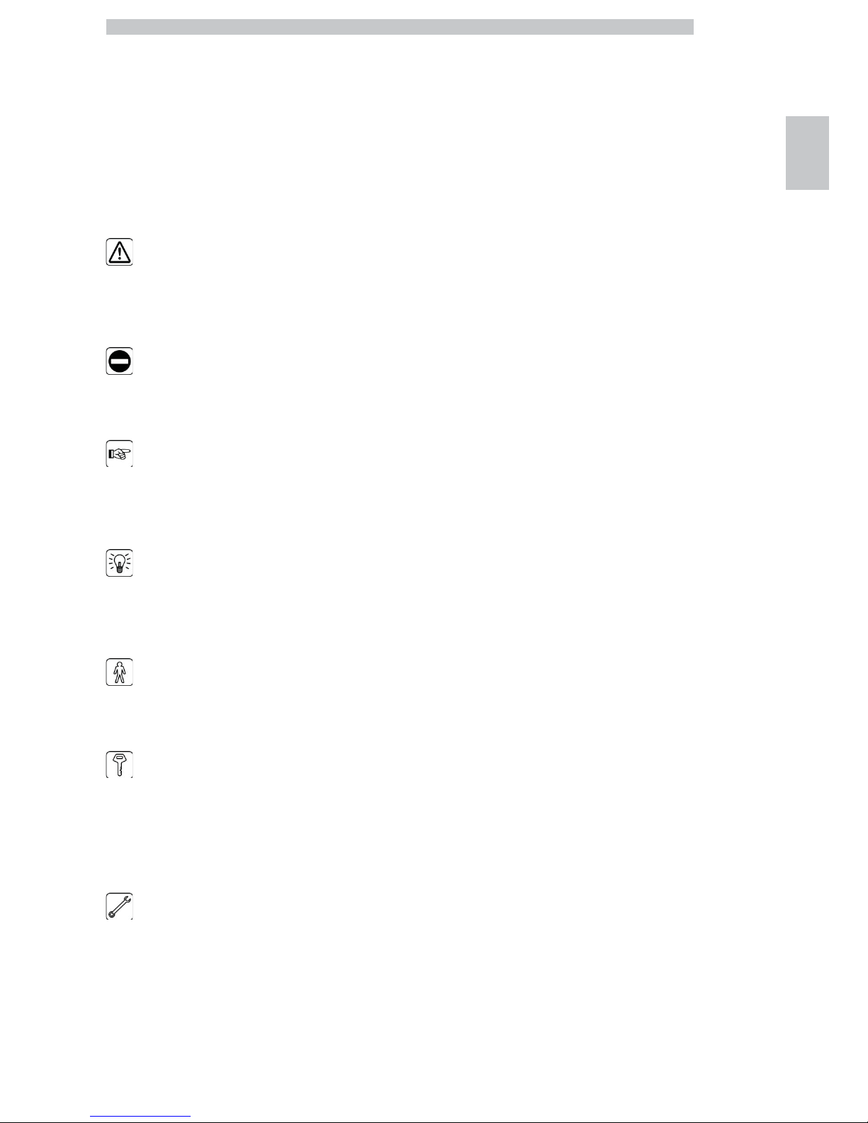
2.2 Symbols used
This publication contains various warnings which indicate
different degrees of danger or skills required.
The symbol is integrated with a message suggesting use
procedures or actions and providing useful information for
the correct operation of the machine.
Warning
Indicates dangerous situations for the users, supply
operators and maintenance technicians dealing either with
the vending machine or the product to be dispensed.
Prohibition notice
It is used to highlight actions/operations not to be
performed.
Important
Indicates the operations for keeping the vending machine
in good working order.
Recommended solutions
Indicates alternative procedures that make the
programming and/or maintenance operations quicker.
User
Indicates the user of the vending machine. This person is
not authorized to carry out any cleaning or maintenance
operation.
Supply operator
Indicates operations to be carried out only by personnel in
charge of supplying and cleaning the vending machine.
Maintenance operations requiring a Maintenance Technician are
not to be performed by the supply operator.
Maintenance Technician
Indicates operations to be carried out by qualified personnel in
charge of maintenance.
The Maintenance Technician is the only person authorized to
keep the MICROSWITCH ENABLING KEY, by which the
security systems can be disabled.
Page 16
English
3
16
3 INFORMATION ON THE VENDING MACHINE
3.1 Information for the
Maintenance Technician
The vending machine must
be installed in a well-lit, dry
area, away from bad
weather and dust, on a
floor suitable to support its
weight.
To guarantee the correct operation and reliability over
time, the following is recommended:
• ambient temperature: from +2°C to +32°C;
• maximum humidity: 80% (not condensed).
For special installations not covered in this publication,
please contact the dealer or the local importer. If this is
not possible, please contact the Manufacturer directly.
The technical service is available for any explanation or
information regarding the correct operation of the vending
machine and to satisfy any request for spare parts supply
or technical assistance.
The Maintenance Technician must carefully read and
respect the safety warnings contained in this manual so
that every intervention concerning installation, starting up,
use and maintenance will be safely carried out.
It is the Maintenance Technician’s absolute responsibility
to give the keys to access the inside of the vending
machine to another operator (Supply Operator), provided
that the Maintenance Technician bears full responsibility
for all work carried out.
This manual is an integral part of the machine and must be
always read carefully before performing any operation.
3.2 Description and intended use
The vending machine is intended for automatic distribution of
coffee and hot beverages (decaffeinated coffee, cappuccino,
chocolate, etc.) and is programmable for every single type of
dispensing dosage. The instant products must be consumed
immediately, and cannot be preserved for a long time.
Any other use is to be considered improper and therefore
dangerous.
Do not place any product
inside the vending machine
which may be dangerous as
a result of unsuitable
temperatures.
Improper use of the vending
machine invalidates all
warranties. The Manufacturer
declines any liability for
damage to property or injury
to persons.
Improper use also includes:
• any use of the vending machine other than the intended use and/or
according to procedures which are not described in this publication;
• any intervention on the vending machine which differs from the
instructions given in this publication;
• any alteration of components and/or safety devices without prior consent
of the Manufacturer or carried out by personnel not authorized for such
operations;
• any location of the vending machine not provided in this manual.
Page 17
English
3
17
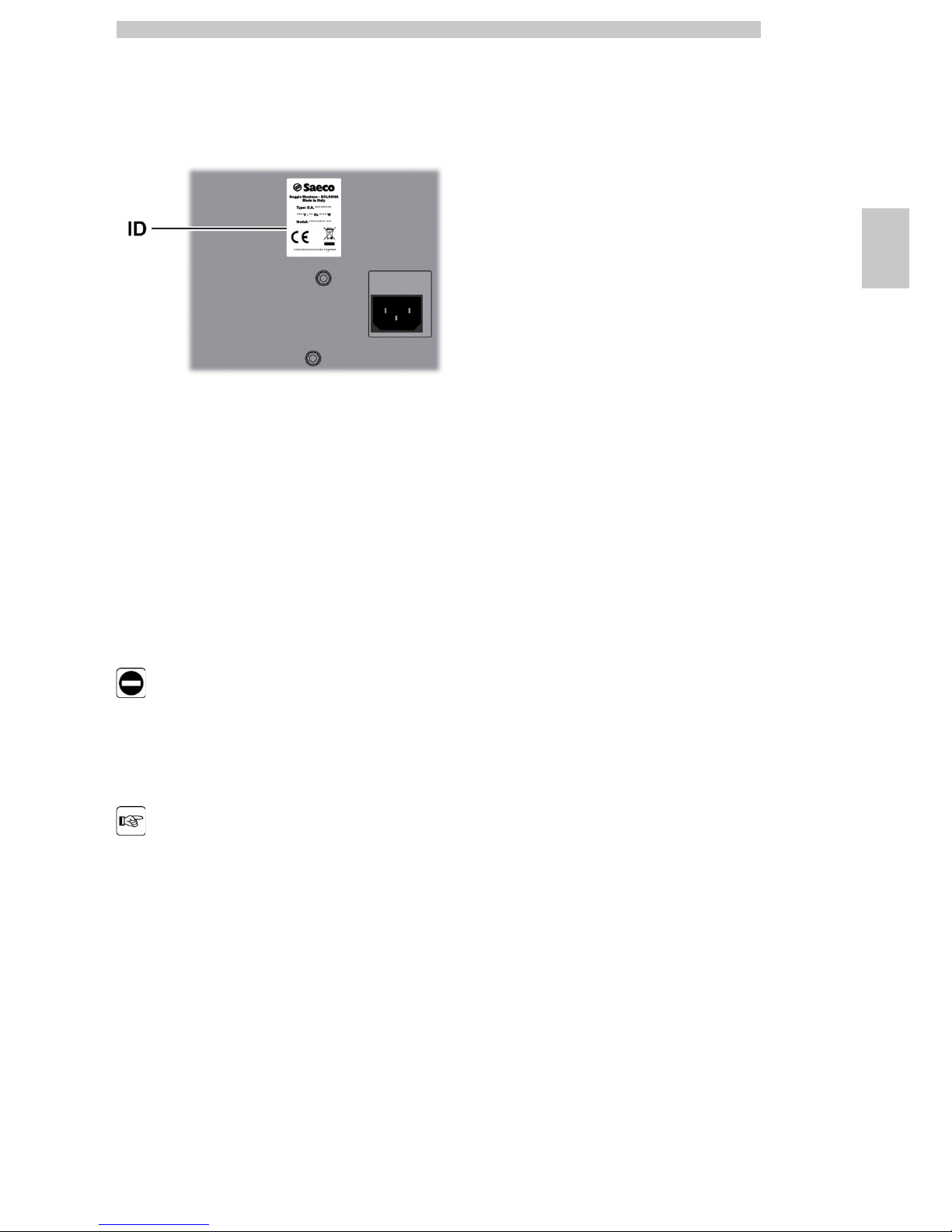
3.3 Vending Machine Identification
The vending machine is identified by the name, model and serial number
which can be found on the relevant data plate.
ID Data plate
The following data can be found on the plate:
• name of Manufacturer;
• marks of compliance;
• model;
• serial number;
• year and month of manufacture;
• supply voltage (V);
• supply frequency (Hz);
• electrical power consumption (W).
It is strictly forbidden to
tamper with or modify the
data plate.
When contacting the
technical service, always
refer to this plate by
indicating the technical
data shown on it.
Page 18
English
3
18
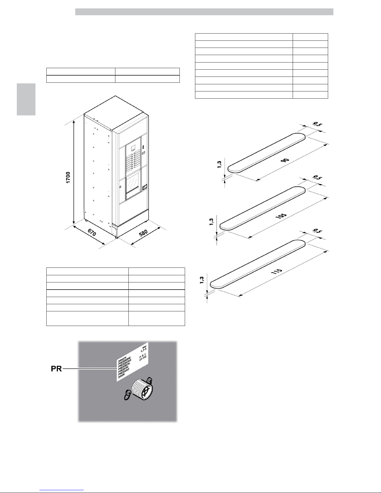
3.4 Technical data
3.4.1 Cristallo 400 EVO
Dimensions (w x h x d) 580 x 1700 x 670 mm
Weight 120 kg
Power consumption see data plate
Supply voltage see data plate
Electric voltage frequency see data plate
Power cord length 1600 mm
Water mains connection 3/4” Gas type
Water mains pressure see data plate
A-Weighted sound pressure level less than 70 dB
PR
Data plate showing minimum and maximum water supply
pressure
Container capacity
Coffee beans 3,5 kg
Decaffeinated coffee 1 kg
Hot Chocolate 3 kg
Milk 2,5 kg
Lemon tea 3 kg
Sugar 3 kg
Cups N° 400
Stirrers N° 400
Coffee capsules N° 310
Stirrer size
Page 19
English
3
19
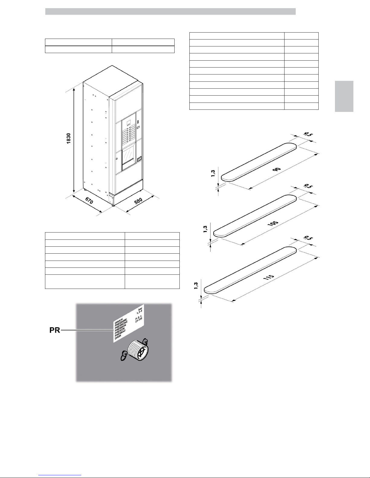
3.4.2 Cristallo 600 EVO
Dimensions (w x h x d) 580 x 1830 x 670 mm
Weight 125 kg
Power consumption see data plate
Supply voltage see data plate
Electric voltage frequency see data plate
Power cord length 1600 mm
Water mains connection 3/4” Gas type
Water mains pressure see data plate
A-Weighted sound pressure level less than 70 dB
PR
Data plate showing minimum and maximum water supply
pressure
Container capacity
Coffee beans 4,2 kg
Decaffeinated coffee 1 kg
Ground coffee 1,6 kg
Hot Chocolate 3 kg
Milk 2,5 kg
Lemon tea 3 kg
Barley 1 kg
Sugar 4,5 kg
Cups N° 550
Stirrers N° 550
Coffee capsules N° 420
Stirrer size
Page 20
English
4
20
4 SAFETY
4.1 Introduction
In accordance with the applicable standards and
regulations, SAECO VENDING has prepared a technical
file relating to the CRISTALLO 400 and CRISTALLO 600
vending machines at its premises, acknowledging the
following standards in the design stage:
- EN 55014 - EN 61000-4-4
- EN 6100-3-2 - EN 61000-4-5
- EN 61000-3-3 - EN 61000-4-11
- EN 61000-4-2 - EN 60335-2-75
- EN 61000-4-3 - EN 60335-1
4.2 General safety regulations
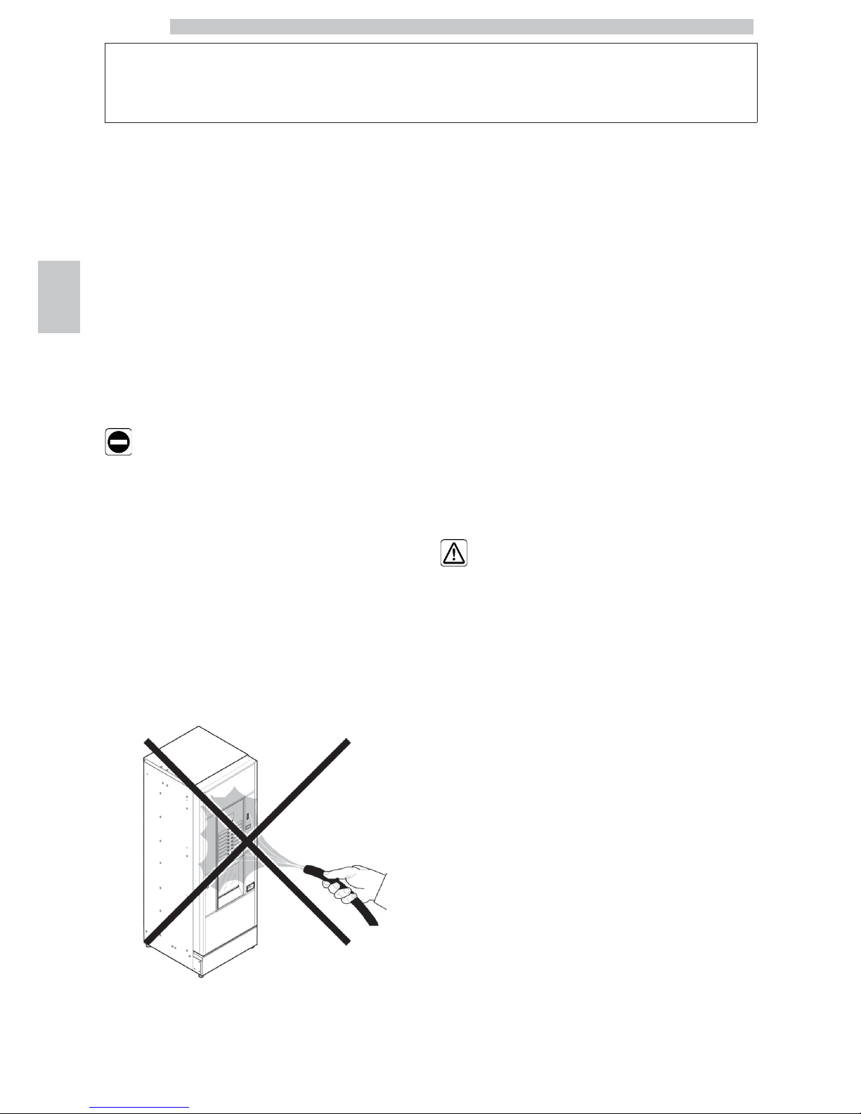
It is forbidden to:
• tamper with or disable the safety systems installed on the
vending machine;
• carry out maintenance on the vending machine without
unplugging it first;
• install the vending machine on the outside. It is advisable to place
it in a dry place where the temperature does not drop below
2°C, in order to prevent any possible freezing.
• use the vending machine for purposes other than those indicated
in the sale contract and in this publication;
• use water jets to clean the vending machine.
• connect the appliance to the mains using multi-sockets or
adapters;
It is compulsory to:
• check the electrical power line for conformity;
• use original spare parts;
• read the instructions contained in this publication and in the
enclosed documents carefully;
• use personal protection devices during installation, testing and
maintenance operations;
• Use a new gasket kit every time you disconnect and then
connect again the machine to the water supply.
Precautions for preventing human errors:
• make the operators aware of safety issues;
• handle the vending machine, either packaged or unpackaged, in
safe conditions;
• have a thorough knowledge of the installation procedures, its
operation and limits;
• dismantle the vending machine in safe conditions, in accordance
with the environmental protection and health and safety laws in
force.
To prevent machining
residues from coming into
contact with the beverages,
dispense about 0.5 l water
for each dispensing path
before definitely starting
the vending machine. The
dispensed beverages can
be consumed only after
performing this operation.
Page 21
English
4
21
In case of failure or
malfunctioning, please refer
only to the qualified
personnel of the technical
service.
The Manufacturer declines
any liability for any damage
caused to property or
injury caused to persons as
a result of failure to
observe the safety
regulations described here.
4.3 Operators' requirements
Three operators with different skills are required in order
to guarantee the safety of the vending machine:
User
Access to the internal part of the vending machine is
forbidden to the user.
Supply operator
The Maintenance Technician assigns the safekeeping of the
access key to the Supply operator who is in charge of
product supply, external cleaning, and starting up /
stopping of the vending machine.
The Supply Operator is
not authorized to carry out
operations which are
indicated as being the
duties of the Maintenance
Technician in this
publication.
Maintenance Technician
The Maintenance Technician is the only person authorized to intervene
and start programming procedures, and perform adjusting, setting up and
maintenance operations on the vending machine.
Access to the service area is
restricted to persons having
knowledge and practical
experience of the appliance, in
particular as far as safety and
hygiene are concerned.
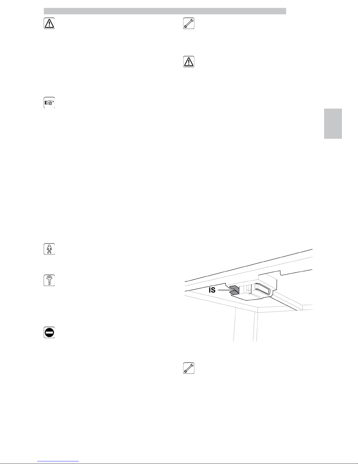
4.4 Safety devices
The vending machine is equipped with:
• a safety switch on the upper door, which cuts off voltage
to all inside components, whenever the front or upper
(Cristallo 400) door is opened;
• a safety switch located on the dispensing outlet door,
which blocks the nozzle arm cycle whenever the door is
opened.
IS Safety switch
Maintenance Technician
In case of programming or setting up operations only the
Maintenance Technician can intervene by inserting the
relevant key into the safety switch and resetting the
voltage even if the door is open.
Page 22
English
4
22
This operation, necessary
for starting up the vending
machine, disables the safety
system.
It must therefore be
carried out by qualified
personnel (Maintenance
Technician) aware of the
risks resulting from the
presence of live or moving
components.
4.5 Residual risks
The dispensing outlet is protected by the door interlocked
by the safety switch. If it is opened during the brewing
cycle, mechanical movement is blocked, but if brewing has
already started, it continues up to the end of the cycle.
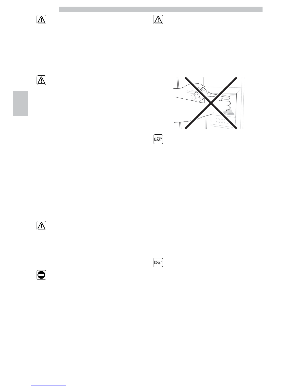
Risk of scalding if hands are
placed inside the outlet
during brewing.
It is forbidden to open the
door and take out the cup
or put hands inside the
outlet during dispensing,
before the brewing cycle is
complete.
Before removing the cup
from the outlet, please
wait for the message
“REMOVE CUP” on
display.
If the outlet door is
opened during the brewing
cycle, the message
“CLOSE SERVICE DOOR”
will be displayed; the
nozzle arm stops and will
not restart until the door is
closed.
It is not possible to brew
further beverages if the
previous cup is not taken
out (see the “Dispensing
outlet microswitch” menu
item).
Page 23

English
4
23
Before brewing another
beverage, check that the
previous one has been
taken out and that the cup
support is empty.
Page 24
English
5
24
5 HANDLING AND STORAGE
5.1 Unloading and handling
Unloading and handling operations after transportation
must be carried out only by qualified personnel and using
suitable equipment.
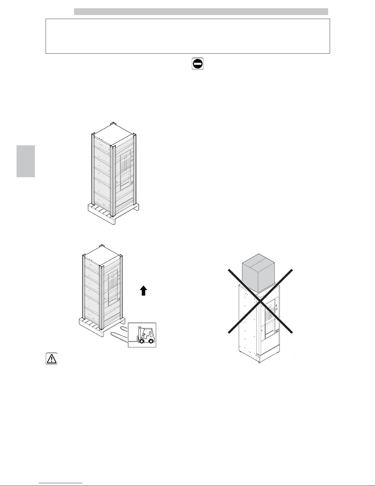
The vending machine is placed on a pallet, protected by a
sack, by a shrink film and four angle bars.
Use a fork-lift to unload the vending machine from the
transport vehicle.
The vending machine must
always be kept in the
upright position.
Avoid:
• dragging the vending machine;
• overturning or laying the vending machine flat during
transport and handling;
• shaking the vending machine;
• lifting the vending machine with ropes or cranes;
• leaving the vending machine exposed to the elements, in
humid areas or close to heat sources.
5.2 Storage
If the vending machine is not installed immediately, it
should be stored in a sheltered area, conforming to the
following instructions:
• the packaged vending machine must be stored in a closed,
dry area at a temperature between 1°C and 40°C;
• do not put other appliances or boxes on the vending
machine;
• it is always good practice to protect the vending machine
from any deposits of dust or other material.
Page 25
English
6
25
6 INSTALLATION
6.1 Warning
The vending machine
cannot be installed
outdoors; avoid placing it
in areas where the
temperature is less than
2°C or more than 32°C
and in particularly dump or
dusty areas. It should not
be installed in places
subject to explosion or fire
hazards, or where cleaning
is done with water jets.
Before unpacking, check that the installation area complies
with the following specifications:
• the power socket must be located in an easily accessible
area, not more than 1.5 meters away;
• the socket voltage must comply with that on the
identification plate;
• the surface or floor must NOT have a gradient of more
than 2°.
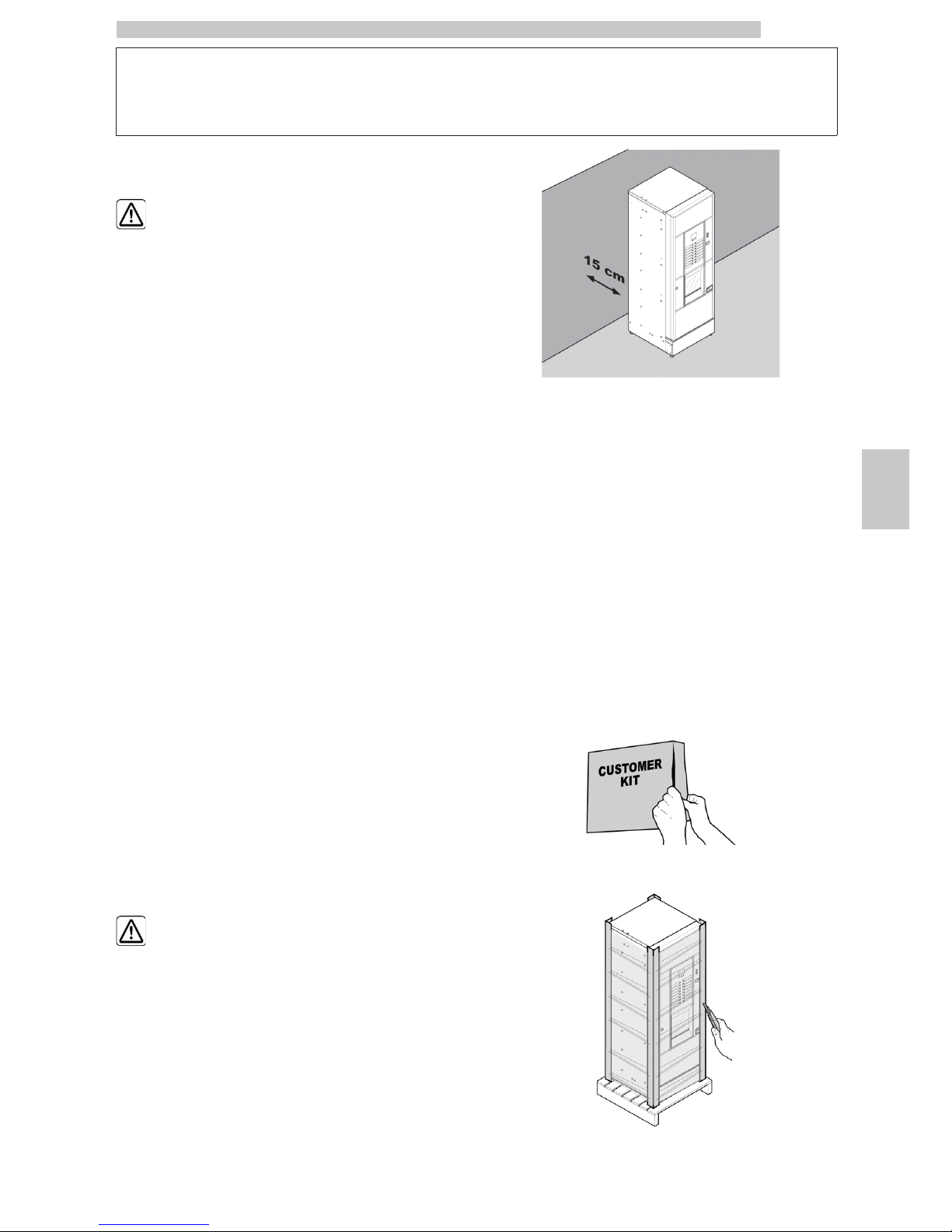
The vending machine must
be installed on a flat
surface.
If the vending machine needs to be positioned close to a
wall, it is necessary to leave a space of at least 15 cm
between the back and the wall in order to keep the air
outlet grille free.
6.2 Unpacking and positioning
On receipt of the vending machine make sure that it has
not been damaged during transportation and that package
has not been tampered with or that internal parts have not
been removed.
A bag, called “CUSTOMER KIT”, is supplied with the
vending machine. It contains the following items:
• Instruction booklet
• Power cord
• Door safety microswitch disabling keys (Maintenance
Technician)
• Product labels and prices
• Instruction plate
Remove the transparent protective film and the four angle
bars.
Page 26
English
6
26
If damage of any kind is found, the courier must be
informed and notice must be given to the importer or the
seller immediately.
If these are not in the purchaser’s country, please contact
the manufacturing company directly.
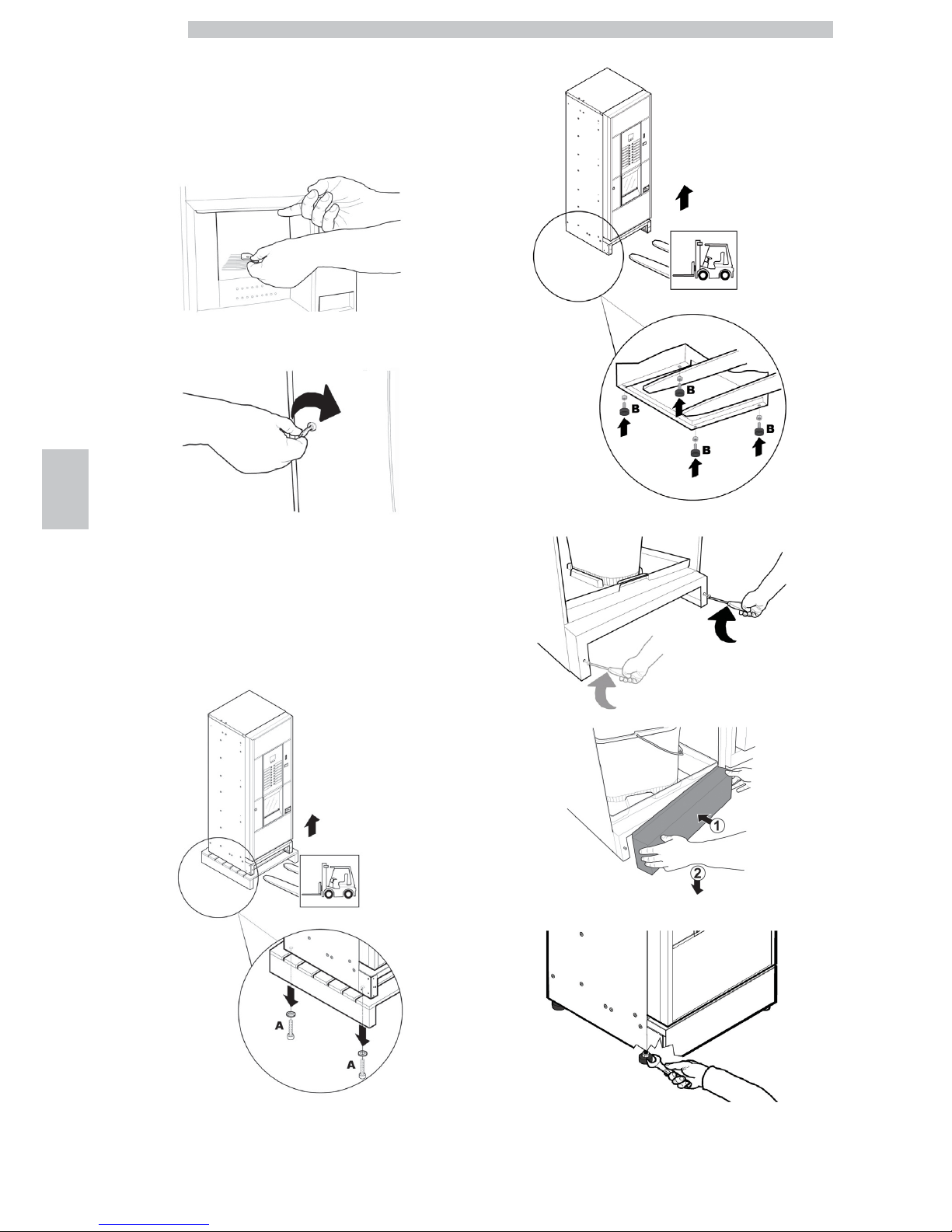
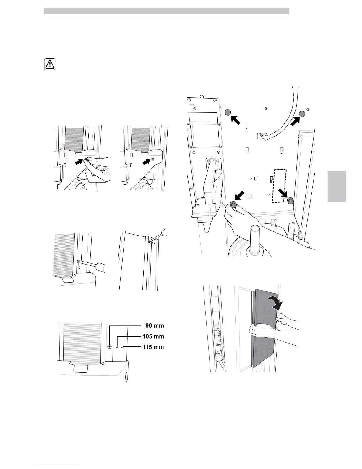
Take the key from the dispensing outlet.
Insert the key into the lock, turn clockwise and open the
door.
From the discharge tank, take out the accessory packet
containing the following items:
• 4 feet;
• 1 key for the brew group.
• 2 screws;
Lift the pallet in a way that the four fixing A screws can be
removed.
Screw the four supporting feet B.
Assemble the base by tightening the two screws as shown in the figure.
Adjust the levelling using the relevant feet.
Page 27
English
6
27
6.3 Use of different-sized stirrers
The vending machine is delivered with the stirrer set designed for use of
90 mm stirrers.
If 90 mm stirrers are used,
make sure that the rubber pin
is inserted in the hole.
To substitute the 90 mm stirrers with those of 105 mm or 115 mm
proceed as follows:
• Unfasten the two screws fixing the stirrer guide;
• Move the stirrer guide into the hole corresponding to the desired
dimension and tighten the two screws.
6.4 Label application
6.4.1 Product labels
Remove the cup dispenser and unscrew the 4 knobs
holding the keypad panel in place.
Remove the keypad panel.
Page 28

English
6
28
Take out the product label sheet included in the customer
kit.
Remove the labels from the product label sheet by
following the pre-cut line.
Cut the labels as shown in the figure to make the left ones
or the right ones.
Left labels
Right labels
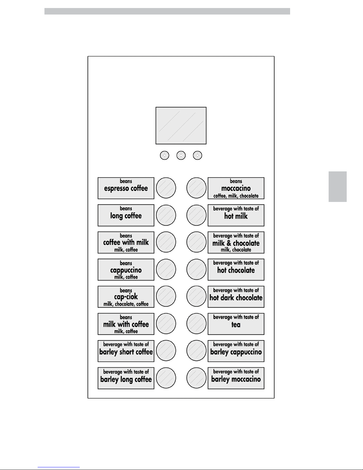
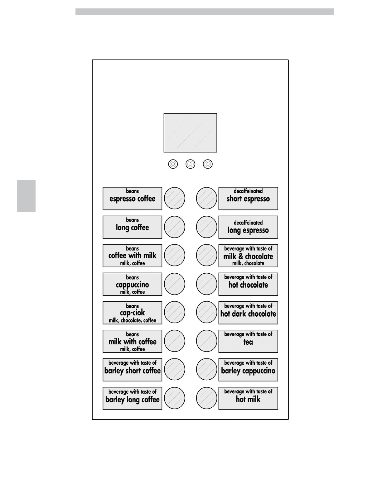
Insert the product labels in the keypad panel.
Check the exact position of the labels against the selection
key.
To make different labels from the ones provided in the kit,
please use the "Labels" module available on our web portal
"Saeco Vending Online" at www.saecovending-online.com.
For printing, we suggest using paper with the following
properties: 170-g matte coated paper.
Page 29
English
6
29
Standard product configuration
Cristallo 400 EVO Espresso Version - 4 instant products
Cristallo 600 EVO Espresso Version - 4 instant products
Page 30
English
6
30
Standard product configuration
Cristallo 400 EVO Espresso Version - 5 instant products
Cristallo 600 EVO Espresso Version - 5 instant products
Page 31

English
6
31
Standard product configuration
Cristallo 400 EVO Capsule Version - 4 instant products
Cristallo 600 EVO Capsule Version - 4 instant products
Page 32

English
6
32
Standard product configuration
Cristallo 600 EVO T.T.T. Version - 5 instant products
Page 33

English
6
33
6.4.2 Instruction plate
Slide the instruction plate into the slot, pressing the flap
inwards.
You need to remove the keypad panel in order to carry
out this operation.
Otherwise, please see instructions in "Product labels".
6.5 Fitting the coffee grounds
bag
Remove the clip from the grounds discharge channel.
Slip the clip into the coffee grounds bag (capacity of 50
litres).
Place the bag on the channel.
6.6 Used capsule collection bag
assembly
(For Capsule version only)
For the assembly of the used capsule discharge duct, carry
out the same operations as described in section "Coffee
ground bag assembly".
6.7 Connection to serial port
The connector on the CPU board and an interface kit can
be used to connect the vending machine to a personal
computer or to the devices supplied by the technical
service in order to perform data detection operations.
6.8 Fitting the payment systems
The vending machine is designed for the installation of
various payment systems, such as:
- parallel banknote reader 24V DC;
- parallel validator 24 V DC
- executive systems (also PRICE HOLDING);
- MDB systems;
- BDV systems;
- cancelling machine 24V DC;
- parallel validator 12V DC (*);
- cashless reader;
(*) optional kit required.
The vending machine is
not supplied with any
payment system, which
must be installed by the
person in charge of its
fitting.
Page 34

English
6
34
After the chosen payment
system has been installed,
the corresponding
parameters can be set
through the programming
menu (see section
“Programming menu”).
To assemble the external
antenna for the Contactless
payment systems it is
recommended to drill the
holes in the area shown in
the figure.
The Manufacturer declines
any liability for any damage
to the vending machine, to
property and/or injury to
persons, caused by the
installation of the payment
system. The responsibility
falls to the person who
carried out the installation.
6.9 Connection to water mains
It is recommended to use
a descaling device for the
water network supplying
the vending machine,
especially for water with a
high calcium and
magnesium content (hard
water).
Connect the vending
machine to drinking water
mains with pressure
between 0.15 MPA and
0.8 MPA (1.5 and 8 bar),
see data on the label.
Page 35

English
6
35
Before connecting the
appliance to water
network, please read and
follow the applicable
regulations in force in your
country.
Remove the cap from the coupling placed on the vending
machine back panel. Connect the water network hose (supplied
with the appliance) to the vending machine 3/4" Gas coupling.
The water mains pipe
should be certified according
to the standard IEC 61770.
The new hose-sets supplied
with the appliance are to be
used and that old hose-sets
should not be reused.
6.10 Connection to the electric
network
The Maintenance Technician,
who is responsible for the
installation of the vending
machine, must ensure that:
• the electric system complies with current safety regulations;
• the supply voltage corresponds to that indicated on the data plate.
If in doubt, do not proceed
with the installation and ask
qualified and authorized
personnel to check the
system accurately.
The vending machine is equipped with a power cord which must be
plugged into the appropriate socket on the vending machine back panel.
Page 36

English
6
36
Do not use adapters or multi-sockets.
Make sure that the electrical
plug is easily accessible even
after installing the machine.
Page 37

English
7
37
7
DESCRIPTION OF CONTROLS FOR CRISTALLO 400-600
EVO
7.1 Display
The display shows the messages during standard
operation, programming and maintenance modes.
7.2 Keypad
Each key function changes
according to the vending
machine mode (ordinary
dispensing or programming
mode).
Each key has a double function that varies according to the
vending machine status (standard operation or
programming).
T1
Set 1 pre-selection
T2
Set 2 pre-selection
7.3 Key description in standard
operation mode
7.3.1 “+” Key - Sugar Quantity
Increases the quantity of sugar in the selected beverage.
Press the key before selecting the beverage.
The preselection remains active for 8 seconds.
7.3.2 “-” Key - Sugar Quantity
Decreases the quantity of sugar in the selected beverage.
Press the key before selecting the beverage.
The preselection remains active for 8 seconds.
7.3.3 Set 1 Pre-selection button
The function connected to the button may be chosen from
the following options:
A. Beverage 9
B. Pre-selection of beverages 17-32
C. Disabled
7.3.4 Set 2 Pre-selection button
The function connected to the button may be chosen from
the following options:
A. Beverage 10
B. Pre-selection of beverages 33-48
C. Disabled
7.3.5 Keys (1 to 16)
By pressing these keys, the programmed beverages are
dispensed.
Page 38

English
7
38
7.4 CPU card keys
The CPU electronic card has 4 keys enabling the
Maintenance Technician to carry out programming or
maintenance operations.
P1 Programming menu key
P2 Maintenance menu key
P3 Machine Ready / Free Button
7.5 5-button Keypad
The 5-button keypad allows for the use of 5 quick controls
without entering the programming or maintenance menu.
Key 1 : Free selection
It allows a free selection.
Key 2 : Washing
It performs a wash cycle of mixing bowls.
Key 3 : Total counter
It displays total and partial counters for products for 5
seconds.
Key 4 : Reset
Machine error reset activates the reset procedure for
selection errors when snack slaves are present.
Button 5: CUP / FOOD CHECK and SNACK
SUPPLY
• Machine without snack slaves
Enables the dispensing of one cup.
• Machine with connected snack slaves
Reset for food error. Restores function of the selections
blocked following an error 75.
Restore independence. If the independence management is
enabled, press the key to set the enabled quantities for
each spiral to the maximum value.
In practice, the person in charge of refilling the snack
vending machine should press this key to report that the
products have been fully refilled and checked.
Alternatively, select product 997 within 20 seconds after
closing the door or switching the vending machine on.
Page 39

English
8
39
8 SUPPLY AND STARTING UP
8.1 Container Configuration
The containers delivered
are designed to dispense
the following products:
Cristallo
400 EVO
Cristallo
600 EVO
- 4 instant
products
Cristallo
400 EVO
Cristallo
600 EVO
- 5 instant
products
Cristallo
400 EVO
capsules
Cristallo
600 EVO
capsules
Cristallo
600
EVO
T.T.T.
Container 1
Tea Tea Tea Tea
Container 2
Milk Milk Milk Milk
Container 3
Hot
Chocolate
Hot
Chocolate
Hot
Chocolate
Hot
Chocolate
Container 4
Barley Decaffeinated Decaffeinated Decaffeinated
Container 5
not present Barley not present
Pre-ground
Coffee
8.2 Instant product supply
Open the cover of the container to be supplied.
Pour the instant product into the container.
Close the container cover.
Page 40

English
8
40
8.3 Sugar supply
Lift the cover of the sugar container and fill the container
with sugar.
Close the container cover.
8.4 Coffee bean supply
Remove the container cover.
Put coffee beans into the container.
Replace the cover on the container.
8.5 Capsule refill
Loosen the knob to the right of the hopper.
Rotate the hopper.
Remove the container cover.
Page 41

English
8
41
Pour the capsules into the hopper.
Replace the cover on the container.
Return the hopper to the vertical position.
Tighten the previously loosened knob.
For a perfect refill, shake
the hopper during the
refilling operation and then
move the capsules by
hand.
8.6 Dose calibration
The vending machine is delivered with standard calibration
values set by the manufacturer.
The quantity of coffee powder is set to 7.0 gr.
Dose calibration can be performed by means of two
calibration levels:
• remove the cover;
• free the adjusting lever from the rack and put the internal
divider pulling peg into one of the 4 possible positions in
the basic coffee quantity area (7 gr - 8 gr - 9 gr - 10 gr);
• move the adjusting lever into the rack and select the slot
corresponding to the dose required.
Page 42

English
8
42
8.7 Coffee grinding calibration
Turn the ring until the required results are obtained.
After any calibration three selections are necessary before
the new setting becomes effective.
8.8 Stirrer supply
Use stirrers suitable for
automatic vending, without
imperfections and
conforming to the
dimensions indicated in
"Technical Specifications".
Remove the metal counterweight from the stirrer guides.
Introduce the stirrers with their packing band into the
column; once they are placed on the bottom, cut and
remove the band.
When loading is complete, reinsert the metal
counterweight.
Make sure the stirrers have no burrs, are not bent and are
all placed horizontally.
Page 43

English
8
43
8.9 Cup supply
Use only cups suitable for automatic dispensing. Do not
press them against each other during the loading
procedure.
Do not try to turn the
column manually.
When installing, with the cup dispenser empty, proceed as
follows:
• remove the cover of the cup dispensing tube.
• load two of the most accessible tubes.
• replace the cover on the cup columns.
8.10 First start-up of the vending
machine
Supply the vending machine (following the instructions
given previously) and plug it into the power supply (see
section "Power Grid Connection").
Now the message "Cristallo 400 / Cristallo 600" appears
on the display and the self-diagnosis phase is activated to
check the correct positioning of the machine devices.
During the self-diagnosis phase, the following devices are activated:
the brew group and the nozzle arm, to get a correct starting position;
if necessary, also the cup release motor, the cup holder and the
stirrer/sugar dispenser will be activated.
Instant products and coffee boilers are refilled also during the initialisation
phase (*).
When the initialisation is complete the warming phase starts and the
heating elements of the boilers are automatically switched on.
(*) During the initial start-up of the machine make sure the boilers are
actually full by starting the Maintenance and performing a refill of the coffe
boiler and a wash cycle
Carry out the grinder adjustment as indicated in the instructions at
section "Coffee Grinder Adjustment" after refilling the water circuit.
8.11 Water circuit filling
At first VM start-up, the boiler is filled automatically.
8.11.1 Filling the boiler manually
After switching the vending machine on it is possible to fill
the boiler by activating the following procedure:
Procedure A
• press the P2 key to enter the maintenance menu;
• Enter the Maintenance/Washes menu and start the
automatic washing cycle;
Procedure B
• press the P2 key to enter the maintenance menu;
Page 44

English
8
44
• Enter the Maintenance/ Boiler Refill menu and start the
automatic refill cycle;
The rinsing operation must
be repeated until water
flows out of the brewing
nozzles regularly.
8.12 Cleaning the parts in contact
with foodstuffs
Clean all the parts of the VM which are in contact with
foodstuffs.
• Wash your hands carefully.
• prepare a chlorine-based anti-bacterial cleaning solution
(these products can be purchased at the chemist’s)
following the concentrations indicated by the product
instructions.
• Remove all the product containers from the vending machine.
• Remove the container lids and the product channels.
Plunge all items into the previously prepared solution.
8.13 Use of the vending machine
The operating instructions
are contained in the data
plate provided in the
vending machine front.
The beverage selection mode is indicated in chapter
"Operation and Use".
Page 45

English
9
45
9 PROGRAMMING AND MAINTENANCE MENU
This section illustrates how
to set up or modify the
vending machine
programming and
maintenance settings.
It is therefore necessary to
read it carefully, and
intervene only when the
correct sequence of
operations to be performed
is fully understood.
9.1 Key description of programming
and maintenance phases
To scroll through the vending machine menu, the keys described
below are used.
“e” Key: ENTER
By pressing this key it is possible to enter the following
programming or maintenance level. It is also possible to
modify or confirm the values set in the entries of the
programming or maintenance menus.
“c” Key: CANCEL
By pressing this key it is possible to go back to the
previous level of the programming or maintenance menu.
It is also possible to avoid storing the previously modified
values.
“v” Key: DOWN
Pressing this key it is possible to access the previous entry
inside the same level. If used after a setting modification
request, the value of this setting decreases.
“^” Key: UP
By pressing this key it is possible to access the next entry
inside the same level. If used after requesting the change of
a setting, the value of this setting increases.
Page 46

English
9
46
9.2 Programming menu
The structure of the programming menu is indicated in
section “Structure of the Programming Menu”.
The section “Description of Messages in the Programming
Menu” describes all the entries in the programming menu.
9.2.1 Access to the programming
menu
Open the door, disable the safety device (see section
“Safety Devices”) and press the P1 key to enter the
programming menu.
If no password has been assigned, the programming menu
is entered directly.
If a password was assigned
to the vending machine to
enable the programming
menu, the message
"PASSWORD 000000" will
appear on the display with
a flashing cursor on the
first digit.
Now the password should
be entered using the UP
and DOWN keys. Confirm
the digit entered by
pressing the ENTER key.
Proceed as follows to exit the programming menu and
return to standard operation of the vending machine:
• Press the CANCEL button repeatedly until "EXIT ?"
appears. Select YES and press ENTER;
• remove the key from the safety switch in order to turn off
the vending machine;
• close the door and wait for the self-configuration process
to end.
Page 47

English
9
47
9.2.2 Structure of the
programming menu
ITEM NO.
MENU ITEM
1. SYSTEM MANAGEMENT
1.1. VM Code
1.2. Stops *
1.2.1. Stop coffee C
1.2.2. Stop beverages
1.2.3. Reset
1.3. Water Filter *
1.3.1. Last filter change
1.3.2. Remaining qty
1.3.3. Filter limit
1.3.4. Filter reset
1.3.5. Filter enabled
1.4. Boiler 1 temp.
1.4.1. Min. Temperature
1.4.2. Max. Temperature
1.5. Energy save
1.5.1. Eco timeout
1.5.2. Stand-by timeout
1.6. Rinsing cycle *
1.6.1. Automatic
1.6.2. Programmable
1.7. Pre-grinding
1.8. Heating/cooling
1.8.1-5 Instant prod. preheat.
1.8.2. Coffee preheating
1.8.3-5 Cooling *
1.8.4. Capsules Preheating
1.9. EV Water Assign *
1.10. Clock *
1.10.1. Time
1.10.2. Date
1.10.3. Date/time format
1.10.4. Disable
1.11. On/Off time *
1.11.1. On 1
1.11.2. Off 1
1.11.3. On 2
1.11.4. Off 2
1.12. Stirrer
1.13. Cup Management *
1.13.1. Cup Dispenser
1.13.2. Disp. outlet micro
1.13.3. Cup Sensor
1.14. Sugar *
1.14.1. Cup Sugar Delay
1.14.2. Sugar
1.14.3. Sugar earlier
1.14.4. Sugar Break
1.15. nozzle arm *
1.15.1. Arm Backwards *
1.16. Display settings
1.16.1. Brightness
1.17. Pulse counter *
1.18. Multiple beverage *
1.18.1. Multiple beverage
1.18.2. Enable Mult. bev.
1.18.3. Free
1.19. Enable reset *
1.20. Buttons *
1.20.1. Button P3 *
1.21. Set 1 Pre-Selection
1.22. Set 2 Pre-Selection
1.23. Programmable texts *
1.23.1. Dispensing
1.23.2. Out of service
1.23.3. Set1 Pre-selection
1.23.4. Set2 Pre-selection
1.23.5. Default Messages
1.24. Audit Device *
1.24.1. Protocol
1.24.2. EA1..2 (Events)
1.24.3. EA3..5 (Readouts)
1.24.4. LA1-Prices Lists
1.24.5. PA - Products
1.24.6. VA1..3 Sales
1.24.7. BA1-CA15-Cash
1.24.8. DA1..7-CashLess
1.24.9. Quick Reading
1.24.10. Extended Time-outs
1.25-8 Tube emptying time *
1.26. Audit Msg. Enable *
1.27. Capsule Type
1.28. Water compensation
1.28.1. Capsules
1.28.2. Beans
1.29. Lighting Type
1.30. Change Password *
1.30.1. Password prog.
1.30.2. Service Password
1.31. Complete menus
1.32. Default Menu *
1.32.1. Factory default
1.32.2. Custom Default
1.33. VM Model *
1.34. Language
1.35. Water tank
1.36. System Info
2. PAYMENT SYSTEMS
2.1. Protocol
2.2. Coin validator
2.2.1. Enable
2.2.2-6 Coin Values
2.3. Banknote validator
2.3.1. Enable
2.3.2. INHIBITION LEVEL
2.3.3-3 Banknote Value
2.4. MDB settings *
2.4.1. Recharge enabled
2.4.2. Max Card Recharge
2.4.3. Max Card Value
2.4.4-16 Coins Enabling
2.4.5. Alt. payout
2.4.6. Max change
2.4.7. Exact change policy
2.4.8. Min Tube Level
2.4.9. Manual Tube Filling
2.4.10. Manual Tube Empty
Page 48

English
9
48
ITEM NO.
MENU ITEM
2.4.11. Commit to vend
2.4.12-16 Bill Enabling
2.4.13. Bill Escrow
2.4.14. MDB Slave Address
2.4.15. no change =no bills
2.5. Max credit
2.6. Multivend
2.7. Overpay Time
2.8. Fixed Zeroes *
2.9. Decimal Digits *
2.10. Credit Wdog *
2.11. Preselection
2.11.1. Pre-selection Time
2.11.2. It cancels pre-selection
2.12. Cash sale cmd sending
2.13. (EXE/PHD) safe mode
3. PRODUCT SETUP
3.1-5 Product Before *
3.2. Beverage Enabling *
3.3. Beverage Preparation
3.3. Sequence
3.3. H2O / Coffee
3.3. Freshbrew Water
3.3. Pre-ground Water
3.3. Fresh inst. time
3.3. Pre-gr.inst.time
3.3. Just water
3.3. % instant product #:
3.3. % pump #:
3.3. Instant prod. dose #:
3.3. Inst. prod. water #:
3.3. Include cup
3.3. Sugar
3.3. Beverage test
3.4. Sugar pre-wash
3.5. Prebrewing
3.5.1. Beans
3.5.2. Capsules
3.6. Build your Drink
3.6.1. whitener water
3.6.2. sugar water
3.6.3. sugar, whitener water
3.6.4. coffee aroma water
3.6.5. whitener single dose
3.6.6. Sugar
3.6.7. espresso %
3.7. Ingredient management
3.7.1. Enable
3.7.2. Read from USB KEY
3.7.3. Display
3.7.4. Write on USB KEY
4. SALE MANAGEMENT
4.1-100 Price table
4.2. Beverage price
4.2.1. Normal
4.2.2. Differentiated 1 *
4.2.3. Differentiated 2 *
4.2.4. Card *
4.3. Snack 1 Prices
4.3.1. Normal
4.3.2. Differentiated 1 *
4.3.3. Differentiated 2 *
4.3.4. Card *
4.4. Snack 2 Prices
4.4.1. Normal
4.4.2. Differentiated 1 *
4.4.3. Differentiated 2 *
4.4.4. Card *
4.5. Free
4.6. Free On
4.7. Free Off
4.8. Diff Prices 1-On
4.9. Diff Prices 1-Off
4.10. Diff Prices 2-On
4.11. Diff Prices 2-Off
5. SNACK 1
5.1. Enable
5.2. Enable Refrigerat.
5.3. Model
5.4. Food mode enabled
5.5. Temperature 1
5.6. Defrost Time
5.7. Defrost Interval
5.8-8 Food Mode Settings
5.8.9. Alarm Temperature
5.8.10. Alarm timeout
5.8.11. Refill allarm timeout
5.9. Door Heaters
5.10. Show temperature
5.11. Photocells
5.11.1. Photocell Enabled
5.11.2. Max motor overtime
5.11.3. Disable selection
5.11.4. Photoelectric cells block
5.11.5. Credit Return
5.12. Capacity ctrl enabled
5.13. Capacity
5.14. Enabled groups
5.15. Groups
6. SNACK 2
6.1. Enable
6.2. Enable Refrigerat.
6.3. Model
6.4. Food mode enabled
6.5. Temperature 2
6.6. Defrost Time
6.7. Defrost Interval
6.8-9 Food Mode Settings
6.8.10. Alarm timeout
6.8.11. Refill allarm timeout
6.9. Show temperature
6.10. Photocells
6.10.1. Photocell Enabled
6.10.2. Max motor overtime
6.10.3. Disable selection
6.10.4. Photoelectric cells block
6.10.5. Credit Return
6.11. Capacity ctrl enabled
6.12. Capacity
Page 49

English
9
49
ITEM NO.
MENU ITEM
6.13. Enabled groups
6.14. Groups
(*) = Visible only if complete menus are enabled.
Page 50

English
9
50
9.2.3 Description of messages in the programming menu
DISPLAY Description
1. The SYSTEM MANAGEMENT items are:
SYSTEM MANAGEMENT
…
1.1. Enables an identification code to be assigned to the vending machine.
VM Code
531000
1.2.
Enables setting of the maximum amount of beverage or coffee.
Once the maximum amount is reached, the vending machine stops dispensing the relevant beverages.
The first digit on the left (“00000”) refers to the quantity of product dispensed since the last “RESET” (partial
counters).
The right hand digit, preceded by “LIM”, shows the maximum dispensable quantity (value may be modified).
Stops
…
1.2.1. Enables setting of the maximum number of coffee cups to be dispensed before the stop.
Stop coffee C
1.2.2. Enables setting of the maximum number of beverages to be dispensed before the stop.
Stop beverages
1.2.3. Enables resetting of all partial counters relative to product quantity stop functions.
Reset
1.3. Allows the use of the water filter to be checked.
Water Filter
…
1.3.1. Date of the last filter reset.
Last filter change
31.01.2008
1.3.2.
Number of litres of water that can still be dispensed before the filter needs to be
regenerated.
When this value is less than 1, a Warning (W83) is recorded in the Error LOG.
Remaining qty
95
1.3.3. Number of litres of water that can still be dispensed from the filter.
Filter limit
100
1.3.4.
Select YES to indicate a new filter has been installed
This operation returns “Remaining Qty” to the same value as “Filter Limit” and the date in
the “Last Filter Change” is changed to today’s date.
Filter reset
1.3.5.
Enables management of the "Remaining Qty" countdown.
Important
From the maintenance menu (button P2 on the CPU), you can access "Water Filter", "Last
Filter Change", "Remaining Qty" and "Filter Reset".
Filter enabled
yes
1.4. It enables setting the coffee boiler management parameters.
Boiler 1 temp.
00
1.4.1.
It allows you to set the temperature that the vending machine keeps for a few minutes after
a beverage has been brewed.
The set value is expressed in centigrade.
Min. Temperature
90
1.4.2.
It allows you to assign the temperature to which the vending machine is brought after a
certain time from the last dispensing, so that the natural lowering of the temperature of the
hydraulic circuits can be compensated.
The set value is expressed in centigrade.
Max. Temperature
100
1.5.
The “Stand-by” and “ECO” modes allow reducing the energy consumption of the machine.
It is possible to select one or both modes.
Energy save
…
Page 51

English
9
51
DISPLAY Description
1.5.1.
The “ECO” mode is activated after some minutes of inactivity which can be set by means of
this menu option. By setting it to zero the function is disabled.
In “ECO” mode, the target temperature of the boiler is reduced by a preset value (see the
following menu option).
The vending machine remains in its “Ready” status and no message is shown to the user.
To exit the "ECO" mode, press any button or insert some credit.
When "ECO" mode is deactivated, the target temperature for boiler 2 is restored and the
machine starts the warm-up phase.
Eco timeout
1.5.2.
The “Stand-by” mode is activated after some minutes of inactivity which can be set by
means of this menu option. By setting it to zero the function is disabled.
In“Stand-by” mode the coffee and steam boilers are turned off (instant product boiler
remains on) and the display shows the message “Stand-by”.
To exit the “Stand-by” mode, press any button or insert some credit.
When normal operation is restored, the boilers are turned on and the vending machine
starts the warm-up phase.
Stand-by timeout
1.6. It allows enabling of the automatic rinsing of the mixing bowls.
Rinsing cycle
yes
1.6.1.
The automatic rinsing is performed as follows: the first rinsing takes place 10 minutes after
the “machine ready” status; if necessary, other rinses occur 7 hours after the last dispensing.
Automatic
1.6.2.
Programmable
1.7. Enables instant pre-grinding of the coffee dose.
Pre-grinding
yes
1.8.
Allows setting timing and amounts for preheating and precooling for instant product circuits
and for the coffee brew group.
Heating/cooling
00
1.8.1-5
Settings for the preheating of water circuits (cups/mixers).
Before dispensing a hot product, a hot rinse of the circuit must be performed, if:
the circuit remained idle for a longer time than that set in the “Timeout Heat. Mixer” and
the amount of water expected for the instant product is <=120 units.
Or if:
The circuit has to be used for a hot product after the same had been used for a cold
product.
The options in this menu allow setting the amount of water used for rinsing each water
circuit and the time of inactivity (expressed in minutes) after which the rinse starts.
Important note:
by setting the time of inactivity to zero preheating is disabled.
Instant prod. preheat.
1.8.1.6.
Mix. Heat Time-out
1.8.2. Settings for the preheating cycle of the brew group.
Coffee preheating
1.8.2.1.
Time (expressed in minutes) of brew group inactivity after which the group starts
preheating.
By setting it to 0, the preheating is disabled.
Operation after(min)
1.8.2.2.
Increase in the water dose (in ml) for the first coffee (by first coffee we understand the
coffee for which the preheating of the brew group is activated).
Extra Coffee Dose
Page 52

English
9
52
DISPLAY Description
1.8.3-5
Settings for the pre-cooling of water circuits (cups/mixers).
Before dispensing a cold product, a cold rinse of the circuit must be performed, if:
the circuit for cold products has to be used after the same mixer had been used for hot
products.
Or if:
the circuit remained idle for a longer time than set in the “Mixer Cool. Timeout” option
(circuit tubes after cooler now contain hot water).
The options in this menu allow setting the amount of water used for rinsing each water
circuit and the time of inactivity (expressed in minutes) after which the rinse starts.
Important note:
by setting the time of inactivity to zero pre-cooling is disabled.
Cooling
1.8.3.6.
MIXER COOL. TIMEOUT
1.8.4. Settings for the capsule group preheating cycle.
Capsules Preheating
1.8.4.1.
Time (expressed in minutes) of capsule group inactivity after which the group starts
preheating.
By setting it to 0, the preheating is disabled.
Operation after(min)
1.8.4.2.
Increase in the water dose (in ml) for the first capsule coffee (the first coffee is intended as
being the one for which the capsule group preheating is activated).
Extra Caps Dose.
1.9.
By setting the “W” value in the product list, hot water will be dispensed.
This menu allows choosing the solenoid valve to be used for dispensing
If the “hot water solenoid valve” kit is installed, set the value to 0 (zero) or select the
solenoid valve operating on the desired circuit among the available ones.
EV Water Assign
…
1.10. Enables setting of the hour, minute, day of the week, day of the month, month and year.
Clock
…
1.10.1.
Time
08:00
1.10.2.
Date
1.10.3. Enables date and time display in US format - enables temperature display in °F
Date/time format
1.10.4.
It hides date and time.
If it is set to YES, date and time will not be displayed.
(however, the clock and its relative functions remain active)
Disable
1.11.
Allows setting the vending machine’s automatic on and off time ranges over the course of a
week.
On/Off time
…
1.11.1.
On 1
00:00
1.11.2.
Off 1
00:00
1.11.3.
On 2
00:00
1.11.4.
Off 2
00:00
Page 53

English
9
53
DISPLAY Description
1.12.
Enables selection of the stirrer dispensing mode.
STIRRER ALWAYS: the stirrer is dispensed anyway;
STIRRER SUGAR: the stirrer is dispensed only if the beverage is served with sugar;
STIRRER SUGAR OR BITTER: the stirrer is dispensed for all the beverages which should be served with sugar,
although the user requires them without it.
STIRRER NEVER: the stirrer is never dispensed.
Stirrer
1.13. Cup dispenser settings.
Cup Management
1.13.1.
Cup Dispenser
1.13.1.1. It enables using the cup dispenser.
Enable
1.13.1.2.
It sets the number of cups left in the dispenser when the refill microswitch for the following
cup column has to be activated.
Cup stock
1.13.1.3.
Delay between the time when the cup column falls into the vending machine slot and when
the column motor stops.
Cup Col. Stop Delay
1.13.1.4. Set to YES if the paper cup dispenser is equipped with cup holder positioning microswitch
Tube posit.
micro
1.13.2.
Allows cup detection inside the dispensing outlet.
When checking is enabled, dispensing new products is not allowed until the paper cup of
the previous beverage is still inside the outlet.
Removal is detected by the photoelectric cell (if any) or by opening the dispensing outlet.
Important
If you wish to use the VM with the dispensing door always open, it is necessary to
short-circuit the wiring of the dispensing outlet microswitch.
Disp. outlet micro
1.13.3.
(Optional kit)
Enables management of the cup sensor.
Cup Sensor
1.13.3.1. It enables the cup sensor.
Enable
Page 54

English
9
54
DISPLAY Description
1.13.3.2.
It enables the function that allows to dispense beverages that have different prices if they are
dispensed with or without the cup.
Important
The Set1 = No cup option shall be used to set a discount for beverages dispensed without
the cup.
The machine does not allow to set discounts on the prices but the same result can be
achieved by using the second beverage set and setting the reduced price and deactivating
the cup dispensing for this set.
To save you from copying the recipes of the standard set to set 1, you can select a mode
that, in case of beverages without cup, automatically uses the recipes of the standard set
and the prices of set 1.
You only need to:
programme the beverage standard set with the desired products by setting for each one the
price with the cup included;
set the price of the corresponding beverages of set 1 to the desired value for the sale
without cup (set only the prices, the machine does not need the recipes and all other
beverage parameters of set 1 including the exclusion of the cup);
enter the "System Management" menu and within the cup settings set to YES the "Set1=no
cup" option;
set the mode for selecting beverages without cup.
Set the “Set 1 Pre-Selection” option to pre-selection and/or enable cup sensor (optional kit).
Set1=no cup
1.14. Sugar dispensing settings.
Sugar
1.14.1.
Minimum delay between the time when the cup is dispensed and when the movable sugar
chute moves.
Cup Sugar Delay
1.14.2. Sugar dispenser activation time setting for a single serving.
Sugar
1.14.3.
Set to “no” to have the sugar dispensed after the movable sugar chute downward
movement.
Sugar earlier
1.14.4. Pause in the downward position of the sugar dispensing spout
Sugar Break
1.15. settings for the management of the nozzle arm
nozzle arm
1.15.1.
By setting this option on YES the nozzle arm will move backwards into off position after the
dispensing of each beverage, this allows an instant release of the cup at the next beverage
dispensing and reduces the dispensing time.
Arm Backwards
1.16. Display settings
Display settings
1.16.1. Allows adjusting the display brightness (non-TFT models only).
Brightness
1.17.
Enables selection of whether the 24 V dc electromechanical pulse counter (optional - to be
connected to the CPU card) has to count the coffees or all dispensed beverages.
Pulse counter
Coffee
1.18.
Allows selecting which beverages will be enabled for multiple brewing and the number of
brewings.
Multiple beverage
…
1.18.1. number of brewing procedures for multiple brewing
Multiple beverage
000
Page 55

English
9
55
DISPLAY Description
1.18.2. Allows selecting which beverages will be enabled for multiple brewing
Enable Mult. bev.
1.18.3. enables the free-of-charge dispensing of the multi beverage
Free
1.19. It allows enabling of the “RESET” for data in the statistics maintenance menu.
Enable reset
no
1.20. button settings
Buttons
…
1.20.1. Menu for setting the function of the P3 button
Button P3
no
1.20.1.1. Allows you to enable the P3 button on the CPU board during normal operation.
Free vend key
no
1.20.1.2.
Allows you to choose whether to associate the P3 button on the CPU board to free
product dispensing or to test product dispensing (with no sugar, stirrer or cup).
Free or Test Beverage
no
1.21.
The function connected to the button may be chosen from the following options:
A. Beverage 9
B. Set 1 Pre-selection
C. Disabled
A - Beverage button 9:
this is the default function.
Button 9 functions as a regular button.
B - Set 1 pre-selection: by choosing this function, the button becomes a pre-selection button for the 17-32
beverage set.
When pressed, the vending machine shows the pre-selection message on the display (“ DECAFF ” as default) and
makes the new beverage group available.
C Disabled: pressing the key has no effect.
Set 1 Pre-Selection
…
1.22.
The function connected to the button may be chosen from the following options:
A. Beverage 10
B. Set 2 Pre-selection
C. Disabled
A - Beverage button 10:
this is the default function.
Button 10 functions as a regular button.
B - Set 2 pre-selection: by choosing this function, the button becomes a pre-selection button for the 33-48
beverage set.
When pressed, the vending machine shows the pre-selection message on the display (“ BARLEY ” as default) and
makes the new beverage group available.
C Disabled: pressing the key has no effect.
Set 2 Pre-Selection
…
1.23.
Programmable texts
…
1.23.1.
it allows setting the message appearing on the display when the vending machine is
dispensing a product.
Dispensing
1.23.2. It enables setting the text on the display when the vending machine stops due to a fault.
Out of service
1.23.3.
Allows you to set the message appearing on the display when the pre-selection mode of
button 9 is activated for beverages 17-32.
Set1 Pre-selection
Page 56

English
9
56
DISPLAY Description
1.23.4.
Allows you to set the message appearing on the display when the pre-selection mode of
button 10 is activated for beverages 33-48.
Set2 Pre-selection
1.23.5.
It allows bringing the programmable messages back to their pre-set default value (this is
useful when changing the language is required).
Default Messages
1.24.
It allows selecting the protocol to be used for transferring data from the VMC (DDCMP o
DEX) and which data category has to be transferred during an audit session.
Audit Device
…
1.24.1.
Protocol
1.24.2.
EA1..2 (Events)
1.24.3.
EA3..5 (Readouts)
1.24.4.
LA1-Prices Lists
1.24.4.1.
LA1 Normal Prices
1.24.4.2.
LA1 Diff1 Prices
1.24.4.3.
LA1 Diff2 Prices
1.24.4.4.
LA1 Card Prices
1.24.4.5.
LA1 Free
1.24.4.6.
LA1 Test
1.24.5.
PA - Products
1.24.5.1.
PA2
1.24.5.2.
PA7
1.24.6.
VA1..3 Sales
1.24.7.
BA1-CA15-Cash
1.24.8.
DA1..7-CashLess
Page 57

English
9
57
DISPLAY Description
1.24.9. Delete value = 0 data from EVA-DTS report
Quick Reading
1.24.10. Prolongation of response waiting time from EVA-DTS data players
Extended Time-outs
1.25-8
Allows setting a delay between the end of beverage preparation and the display of the
"Remove cup" message to the user.
Such delay is necessary to allow a complete drainage of the liquid in the dispensing tubes.
Tube emptying time
1/8
1.26.
It allows displaying for a few seconds the selection counters (total and since last reset)
during the machine start-up phase.
Audit Msg. Enable
1.27.
selection of the capsule type used with the machine.
This allows some machine actions to be adjusted according to the peculiarities of each
capsule type.
Capsule Type
1.28.
Water compensation for beverages made from coffee beans and coffee capsules.
The exact quantity of water dispensed by each machine depends on both the construction
tolerances of each water circuit component (pump, flowmeter, tubes, etc.) and the type of capsules
used.
This menu allows you to set a correction "evening out" these differences so that the end result in the
cup is always the same even if the machine is different.
During manufacturing, the optimum values are calculated and stored for each vending machine.
If a FACTORY DEFAULT is carried out or the CPU board is replaced, you need to reset the
correct value by following the simple instructions here below:
• Set the water for the COFFEE beverage = 30
• Dispense 3 beverages, checking their weight and calculating the rounded-up mean value
• If the result obtained is higher or lower than 30, the excess/default value must be subtracted/added
from/to the value set by default
EXAMPLE:
BEVERAGE 1 SEQUENCE 000C
COFFEE WATER = 30
Coffee 1 = 32 g
Coffee 2 = 35 g
Coffee 3 = 28 g
Work out the mean:
32 + 35 +28 = 95 -> 95/3 = 31.6
In this case, 31.6 being the obtained value, the machine is dispensing more water than the set
amount, so you will need to subtract 2 from the value set in the CAPSULE COMPENSATION
menu
If the mean value obtained were 28, you should add 2 to the value set in the CAPSULE
COMPENSATION menu
Water compensation
1.28.1. Allows you to select the water compensation for products made from coffee capsules
Capsules
1.28.2. Allows you to select the water compensation for products made from coffee beans
Beans
1.29.
Allows selecting if the dispensing outlet should be lit during the brewing or the cup
dispensing phase
Lighting Type
Page 58

English
9
58
DISPLAY Description
1.30.
Enables setting of a password or modification of the current one.
The password consists of a number between 000001 and 999999.
The 0000 value (default value) means no password.
To set the password, press the UP and DOWN keys and confirm using the ENTER key.
Change Password
1.30.1. Allows setting a password to access the programming menu.
Password prog.
1.30.2.
Allows setting a password to access the maintenance menu.
Important
If the password is lost, you will have to contact the Saeco Vending Technical Assistance
Service to regain access to the Programming Menus.
Service Password
1.31.
Enables selection of whether the entries of the programming menu should be shown fully or
only partially.
Complete menus
1.32.
Management of default values for machine configurations.
The user can create and recall his own configuration.
Default Menu
1.32.1.
It allows reverting the programmable parameters to factory preset values.
This operation does not reset the product counter.
Factory default
1.32.2. Management of the configuration which has been created by the user
Custom Default
1.32.2.1. Restoring the configuration which has been saved by the user on the machine
Read Custom Default
1.32.2.2. Saving the user machine configuration
Write Custom Default
1.33.
It allows selecting the current model of the vending machine.
The vending machine model is specified on the label located inside the right side panel.
VM Model
1.34.
It allows to select the language to be used by the machine.
The available languages are:
Italian, English, French, German, Spanish, Portuguese, Dutch, Turkish and Russian.
The machine texts can be modified according to the user’s needs to add new languages not included in the default
list.
(Contact the Customer Service for any information).
Language
1.35.
Enables selecting the vending machine's operation under no water conditions.
If NO (default) is selected, the vending machine works as if it were connected to the water
network and tries to refill water every 10 minutes as usual.
If "YES" is set, the VM works as if it were supplied by an independent tank. Indeed, in no
water condition, the vending machine does not try to refill water and goes into ERROR 01.
Water tank
1.36.
"This option allows you to access a page showing the overall machine configuration.
The display shows the following information:
First line: sw version (""x.yy.zz"" format) / program CRC (""abcd"" format)
Example: ""'SW v1.02.12/087c""
Second line: Boot loader version (""xx"" format) and name of the file searched for by the boot loader on the USB
key ("".s19"" extension not displayed)
Example: ""Boot 08SAE_DA5P""
Third line: memory version (""xxx.yyy."" format) and content CRC (""zzz"" format)
Example: ""Mem 123.456.789"""
System Info
2. The entries of the PAYMENT SYSTEMS are:
PAYMENT SYSTEMS
…
Page 59

English
9
59
DISPLAY Description
2.1.
Protocol
2.2.
Allows enabling of the parameters of the parallel coiner, the mechanical coiner, the
cancelling machine and the choice of values to be assigned to the single money channels.
Coin validator
…
2.2.1.
By setting "Y", the parallel coiner, the mechanical coiner and the cancelling machine control
are enabled.
If set on "N", the parallel coiner (if any) connected to the vending machine will be excluded.
Enable
no
2.2.2-6
It allows you to set the value of the coins forwarded to the vending machine by the parallel
coiner, the mechanical coiner and the punching machine.
The following "PAIRING TABLE" indicates how channels and related payment systems are
connected to each other.
Coin Values 1/6
0.00
2.3.
It enables the parameters of the parallel banknote validator and the choice of values to be
assigned to single banknote channels.
Banknote validator
…
2.3.1.
By setting “Y”, the management of the parallel reader is enabled.
By setting “N”, a parallel reader which may be connected to the vending machine is always
disabled.
Enable
no
2.3.2. Enables setting of the active level of the banknote reader inhibition signal.
INHIBITION LEVEL
255
2.3.3-3
Enables setting of the value of banknotes transferred to the vending machine from the
parallel reader.
Banknote Value
…
2.3.3.4.
Banknote
2.4. Enables access to particular functions of the MDB protocol.
MDB settings
…
2.4.1.
It allows disabling or enabling the possibility of performing any Saeco Card recharge operation
By setting RECHARGE = NO the vending machine will only deduct the cost from MDB cards.
Recharge enabled
no
2.4.2.
Enables setting of the maximum credit level, beyond which all recharge operations (if
enabled) are ineffective.
By setting MAX RECHARGE = 20.00, the credit on the vending machine will be transferred
to the card if the sum does not exceed 20.00.
Max Card Recharge
10.00
2.4.3.
It enables to set the maximum credit level, beyond which the card is rejected by the system.
By setting MAX CARD VALUE = 25.00, the vending machine will reject all cards with a credit which
exceeds this amount.
If this card is detected, the display will not show the credit but a “ ——” message will be displayed
and no sale will be carried out.
Max Card Value
10.00
2.4.4-16
Coins Enabling
…
2.4.5.
It enables / disables the use of Alternative Payout for the level 3 MDB change-giving coiner.
By setting "Yes" the change-giver is called on to dispense change.
Change is limited to 255 times the scaling factor (typically € 12.75 for the Euro area - with scaling factor of 5).
By setting “No” change is given by exploiting the machine’s algorithm.
Max. change is 60000 units (typically € 600 for the Euro area).
Alt. payout
no
2.4.6.
Enables setting of the maximum amount of change which can be dispensed by the
change-giving coiner.
Default = 10.00.
Max change
0.00
Page 60

English
9
60
DISPLAY Description
2.4.7.
With MDB coin return, the "no change available" status can be selected through the "CHANGE TABLE".
Note
Even if the no change available message is displayed, the vending machine continues to give change as long as
coins are present in the channels.
The minimum level (the same for all channels) can be set on a special menu item.
Exact change policy
0
2.4.8.
Enables setting of the minimum number of coins in the channels.
Default = 4.
Min Tube Level
0
2.4.9.
Allows the coin return tubes to be filled by hand.
Press Esc to exit the channel loading mode.
Manual Tube Filling
…
2.4.10.
Allows the change-giving coiner channels to be emptied by pressing the beverage selection
keys.
Manual Tube Empty
…
2.4.11.
By setting “N”, the credit inserted can be returned even if no sale has been made.
This function may be useful, for example, for changing banknotes into coins.
By setting “Y”, the credit inserted can be returned as change only after the sale has been
completed.
Default = YES.
Commit to vend
no
2.4.12-16
Bill Enabling
…
2.4.13.
By setting “Y”, an inserted banknote is stored in the escrow position by the banknote reader
(if supported); this function is supported by the banknote reader.
In this way, if the sale fails or the card system fails to charge, the banknote will be returned.
By setting “N”, any inserted banknote goes to the banknote reader’s stacker, so that the
banknotes cannot be returned.
Default = No.
Bill Escrow
no
2.4.14.
When the vending machine is in Master mode, this menu enables setting of the address of any slave connected
vending machine.
If the vending machine is in Slave mode, it enables setting of its address.
Possible addresses are 0x40, 0x48 and 0x50.
Default = 0x40.
MDB Slave Address
0x40
2.4.15. Allows you to disable the bill reader if there is no change.
no change =no bills
…
2.5.
It allows the user to set the maximum credit which can be accepted by the vending machine.
Once this limit has been reached, the payment systems are disabled so that no more credit can be
accepted.
Default = 20.00.
Max credit
255
2.6. Enables the user to use any residual credit to purchase other beverages.
Multivend
no
2.7.
By setting “N” (no), the residual credit will be collected by the vending machine.
It establishes the maximum time (expressed in seconds) beyond which the vending machine collects the displayed
residual credit.
The time is adjustable at intervals of 10 seconds.
Setting “000” the function is disabled.
Overpay Time
180
2.8. Enables setting of the number of fixed zeros of the credit.
Fixed Zeroes
0
2.9. Enables setting of the position of the decimal point of the credit.
Decimal Digits
0
Page 61

English
9
61
DISPLAY Description
2.10.
Enabling this option, an internal control is activated, which resets the communication with
the payment systems if the communication is blocked.
Credit Wdog
0
2.11. Management of pre-selection options
Preselection
2.11.1. Pre-selection time duration (in seconds)
Pre-selection Time
2.11.2.
It enables the current pre-selection cancellation by pressing any button other than sugar
buttons and by pressing the coin return button of the change-giver.
It cancels pre-selection
2.12. It enables the management of the cash sale notification command (for card reader MDB)
Cash sale cmd sending
2.13.
"safe" mode of protocol EXE/PHD.
It does not accept selling controls outside the pre-selection time of the machine.
(EXE/PHD) safe mode
no
3.
PRODUCT SETUP
…
3.1-5
It allows selecting the instant product for which you wish to enable powder dispensing
before water dispensing. This brewing cycle will be carried out only when the quantity of
powder to be brewed does not exceed 34.
Product Before
…
3.2. It allows to enable or disable the beverage keys.
Beverage Enabling
…
3.3.
The vending machine can dispense up to 16 beverages.
Each beverage can be prepared by using ground coffee and/or instant products.
Technicians can select the desired products for the recipe (max 4) and their order of use.
Each component is identified by a number or a letter.
Beverage Preparation
…
3.3.
Defines the beverage ingredients and in which order they are dispensed.
The possible choices are:
0 =does not dispense any product
1 = dispenses product 1
2 = dispenses product 2
3 = dispenses product 3
4 = dispenses product 4
5 = dispenses product 5
6 = dispenses product 6
7 = dispenses product 7
8 = dispenses product 8
C = dispenses coffee beans from coffee hopper no. 2
K = dispenses coffee beans from coffee hopper no.1
L = brews coffee made from capsules
F = brews “fresh brew” coffee using pre-ground coffee
P = brews espresso coffee using pre-ground coffee
B = brews Fresh Brew coffee using coffee beans
W = dispenses hot water
S1 = dispenses syrup product 1 (optional)
S2 = dispenses syrup product 2(optional)
Consequently, the combination of “3C00” or “30C0” or “03C0” will always dispense product 3 and
coffee beans.
The settings of products making up the beverage will be requested according to the sequence.
Important
To obtain the cup only, set beverage sequence to 0000 and block sugar regulation (sugar setting =
“sugar blocked”).
Sequence 1
0C00
Page 62

English
9
62
DISPLAY Description
3.3.
This defines the quantity of coffee to be brewed.
The quantity of dispensable coffee can be adjusted from “1” to “999”.
H2O / Coffee
1
38
3.3.
Sets the quantity of water to be dispensed for the programmed coffee type (C, P, F, or B).
The quantity can be set from 1 to 999.
Freshbrew Water
3.3.
Sets the quantity of water to be dispensed for the programmed coffee type (C, P, F, or B).
The quantity can be set from 1 to 999.
Pre-ground Water
3.3. Instant freshbrew dose
Fresh inst. time
3.3. Instant pre-ground dose
Pre-gr.inst.time
3.3. Defines the amount of hot water to be dispensed.
Just water 1
101
3.3.
It determines the instant powder delivery rate.
The value can be set between 10 and 100.
The lower the value the smaller the powder delivery rate.
% instant product #:
1
3:50
3.3.
It determines the water delivery rate.
The value can be set between 20 and 100.
The lower the value the smaller the water delivery rate.
% pump #: 1
3:50
3.3.
This defines the quantity of instant product to be brewed.
Example: “005” quantity indicates that the motor of the instant product 3 will be activated for 5 tenths of a second.
The quantity of instant product is adjustable from “1” to “100” in steps of 1.
Brewing of the instant product does not occur when the parameter is set at “0000” (in this case water is brewed).
Instant prod.
dose #:
1
3:005
3.3.
It defines the amount of water to be mixed with the instant powder.
Example: “3” indicates that water will be mixed with the instant product 3.
“022” indicates that 22 units of water will be brewed with the instant product.
The reference unit is preset by the manufacturer.
The amount of water can be adjusted from ‘“1” to “999” in steps of 1.
Important -1
If the instant product parameters ("INSTANT PRODUCT - WATER - % INSTANT PRODUCT" % PUMP) are set so as to make the powder dispensing procedure last longer than the water
dispensing one, the vending machine will stop the powder dispensing. This is meant to avoid
insufficient mixer washing.
Readjust the set parameters in order to have a correct dispensing procedure, i.e. the powder
dispensing should stop a few seconds before the water stops flowing out. This is intended to allow
correct mixer washing.
Important -2
If the sequence includes more instant products, the sequence "INSTANT PRODUCT - WATER - %
INSTANT PRODUCT" - % PUMP" will appear for each instant product.
Allows choosing whether the beverage will be dispensed using the cold beverage dispensing kit
Inst. prod.
water #:
1
3:022
3.3. Allows choosing whether the beverage will be dispensed with or without paper cup.
Include cup 1
yes
3.3.
This defines the quantity of sugar to be dispensed with the beverage.
The following "SUGAR TABLE" indicates the effects due to the different settings.
Sugar 1
2
Page 63

English
9
63
DISPLAY Description
3.3.
Enables brewing tests to be carried out on the beverage just set.
By pressing ENTER, the following dispensing buttons are displayed:
Full beverage;
Beverage without sugar, stirrer and cups;
Beverage without powder (soluble/coffee);
Beverage without water.
Beverage
test
1
3.4.
Sugar pre-wash
3.5.
Prebrewing
3.5.1.
Beans
3.5.1.1. Quantity of water for coffee beans pre-brewing
Prebrewing [ml]
3.5.1.2. Coffee bean pre-brewing pause duration
Pre-brew. pause[s/10]
3.5.2.
Capsules
3.5.2.1. Quantity of water for capsule coffee pre-brewing
Prebrewing [ml]
3.5.2.2. Capsule coffee pre-brewing pause duration
Pre-brew. pause[s/10]
3.6. Parameter management for product changes carried out by the user
Build your Drink
3.6.1. Water dose to be dispensed to modify whitener
whitener water
3.6.2. Water dose to be dispensed to modify sugar
sugar water
3.6.3. Water dose to be dispensed to modify whitener and sugar
sugar, whitener water
3.6.4. Water dose for Medium-aroma coffee [ml]
coffee aroma water
3.6.5. Instant whitener quantity for each step [s/10]
whitener single dose
3.6.6. Sugar quantity for each step [s/10]
Sugar
3.6.7.
It allows you to set the percentage of the "fresh"-type dispensing cycle to be carried out
when the group is in the "espresso" position
espresso %
3.6.7.1. Espresso percentage in fresh coffee for light aroma
mild aroma
Page 64

English
9
64
DISPLAY Description
3.6.7.2. Espresso percentage in fresh coffee for medium aroma
medium aroma
3.7.
It allows the user to view the composition of the selected beverage before brewing it.
The ingredients are displayed if, when pressing the selection button, the credit necessary for completing the sale
has not been inserted yet.
The ingredient list of the selected beverage is automatically created starting from the recipe, component by
component.
The ingredient descriptions are uploaded from text files stored on a USB key and saved in the memory.
Once uploading has been completed the USB key can be removed. Files have to be named:
“COMP_001.txt”, “COMP_002.txt”, …, “COMP_008.txt” and must be stored on the USB key root.
Description must be placed on a single row, not exceeding 70 characters.
From the programming menu it is possible to enable/disable the ingredient display, to upload the description files
from the USB device, view the content of the uploaded files, save the descriptions in the memory on a USB
device. The 'file name' / 'beverage component' combinations are indicated below:
“COMP_001.txt” = Instant product 1
“COMP_002.txt” = Instant product 2
“COMP_003.txt” = Instant product 3
“COMP_004.txt” = Instant product 4
“COMP_005.txt” = Instant product 5
“COMP_006.txt” = Instant product 6
“COMP_007.txt” = Instant product 7 or coffee K or capsules L or FreshBrew F or pre-ground P
“COMP_008.txt” = Instant product 8 or coffee C or beans B
Ingredient management
3.7.1. It enables ingredient display in pre-selection mode, component by component.
Enable
3.7.2. It uploads the files with the ingredients from a USB key.
Read from USB KEY
3.7.3.
It displays the content of the uploaded ingredients, component by component, in the text
format used in pre-selection mode.
Display
3.7.4. It saves the description of the beverage components on the USB key.
Write on USB KEY
4. Price management for the products available in the vending machine.
SALE MANAGEMENT
…
4.1-100
99 different price levels can be set.
Each product in the vending machine can have up to 4 price levels; each of them can be
used in a specific situation: Standard range, differentiated range 1 or 2, sales with card.
Price table
4.2.
Enables association of one of the price levels set in the PRICE TABLE to each beverage.
The association can be:
Beverage price
4.2.1.
Standard Price Range.
This is the default price range applied by the vending machine, i.e. the range used when
none of the other 3 available ranges is active.
Normal
4.2.1.1.
Global price setting
It allows selecting the price level to be associated with all the products (use the UP and
DOWN buttons and then ENTER to confirm).
Global price
P00 0.00
Page 65

English
9
65
DISPLAY Description
4.2.1.2.
Single price setting
Allows selecting the price level to be associated with each one of the products (use UP and
DOWN buttons and then ENTER to confirm).
Select the desired product first, and then the price.
Single Prices
B01:P00 0.00
4.2.2.
Differentiated 1 Price Range.
This range can be activated within a time range
Differentiated 1
…
4.2.2.1.
Global price setting
It allows selecting the price level to be associated with all the products (use the UP and
DOWN buttons and then ENTER to confirm).
Global price
P00 0.00
4.2.2.2.
Single price setting
Allows selecting the price level to be associated with each one of the products (use UP and
DOWN buttons and then ENTER to confirm).
Select the desired product first, and then the price.
Single Prices
B01:P00 0.00
4.2.3.
Differentiated 2 Price Range.
This range can be activated within a time range
Differentiated 2
…
4.2.3.1.
Global price setting
It allows selecting the price level to be associated with all the products (use the UP and
DOWN buttons and then ENTER to confirm).
Global price
P00 0.00
4.2.3.2.
Single price setting
Allows selecting the price level to be associated with each one of the products (use UP and
DOWN buttons and then ENTER to confirm).
Select the desired product first, and then the price.
Single Prices
B01:P00 0.00
4.2.4.
Card Price Range.
This function enables the application of differentiated prices if the card is used for payment.
Card
…
4.2.4.1.
By setting CARD PRICES = YES a new menu entry will appear in PRICE MANAGEMENT,
enabling setting the price level to be applied to the product (beverage or snack) if payment
is made by card.
Card Prices
no
4.2.4.2.
Global price setting
It allows selecting the price level to be associated with all the products (use the UP and
DOWN buttons and then ENTER to confirm).
Global price
P00 0.00
4.2.4.3.
Single price setting
Allows selecting the price level to be associated with each one of the products (use UP and
DOWN buttons and then ENTER to confirm).
Select the desired product first, and then the price.
Single Prices
B01:P00 0.00
4.3.
Snack 1 price settings.
The same instructions provided for beverage price settings apply.
Snack 1 Prices
…
4.3.1.
Normal
4.3.1.1.
Global price
P00 0.00
4.3.1.2.
Single Prices
B01:P00 0.00
4.3.2.
Differentiated 1
…
4.3.2.1.
Global price
P00 0.00
4.3.2.2.
Single Prices
B01:P00 0.00
Page 66

English
9
66
DISPLAY Description
4.3.3.
Differentiated 2
…
4.3.3.1.
Global price
P00 0.00
4.3.3.2.
Single Prices
B01:P00 0.00
4.3.4.
Card
…
4.3.4.1.
Global price
P00 0.00
4.3.4.2.
Single Prices
B01:P00 0.00
4.4.
It allows associating each snack product in slave 1 or 2 to one of the price levels set in the
PRICE TABLE.
Snack 2 Prices
…
4.4.1.
Normal
4.4.1.1.
Global price
P00 0.00
4.4.1.2.
Single Prices
B01:P00 0.00
4.4.2.
Differentiated 1
…
4.4.2.1.
Global price
P00 0.00
4.4.2.2.
Single Prices
B01:P00 0.00
4.4.3.
Differentiated 2
…
4.4.3.1.
Global price
P00 0.00
4.4.3.2.
Single Prices
B01:P00 0.00
4.4.4.
Card
…
4.4.4.1.
Global price
P00 0.00
4.4.4.2.
Single Prices
B01:P00 0.00
Page 67

English
9
67
DISPLAY Description
4.5.
Allows you to select if the beverages will be provided free-of-charge, upon payment, or
free-of-charge within a time range.
Free
Never
4.6. Allows the beginning and end of the free-of-charge beverage supply to be set.
Free On
Immgvsd 00:00
4.7.
Free Off
Immgvsd 00:00
4.8. Allows the beginning and end of beverage supply with differentiated prices to be set.
Diff Prices 1-On
Immgvsd 00:00
4.9.
Diff Prices 1-Off
Immgvsd 00:00
4.10. Allows the beginning and end of beverage supply with differentiated prices to be set.
Diff Prices 2-On
Immgvsd 00:00
4.11.
Diff Prices 2-Off
Immgvsd 00:00
5.
Snack 1 (or snack 2) slave settings
A special interconnection kit allows connecting up to 2 slave spiral vending machines to the
vending machine.
Important
The products of the first slave will be identified by the numbers from 111 to 199, while the
products of the second slave will be associated to the numbers from 211 to 299.
The following menus allow the parameters for each of the 2 possible slaves to be set.
SNACK 1
…
5.1. It allows the vending machine to control slave 1 (or slave 2).
Enable
…
5.2.
NO = temperature control disabled, cooling group always OFF.
YES = temperature control enabled.
Enable Refrigerat.
…
5.3.
It selects the machine submodel: the values are 6S for the models with 6-spiral drawers (i.e.
Corallo) and 8S for those with 8-spiral drawers (i.e. Aliseo).
Optimises the fan settings for the specific case of the machine.
Model
…
5.4.
Enables / disables the “food mode”.
This mode enables the machine to check that the food area temperature is always lower than a set value (alarm
temperature).
If the temperature exceeds this limit value for longer than the time set for “Alarm max. time”, the machine
deactivates the selections for the food shelves.
Food mode enabled
…
5.5.
[° C] Allows the setting of the temperature desired inside the machine [Range: 3 .. 30].
The control turns off the cooling group if the set value is reached and it turns it on if the
temperature is higher than the target plus 1°C (as long as the technical specifications of the
cooling group are respected).
Temperature 1
…
5.6.
[min] It allows setting how many minutes the cooling group will be switched off to carry out
the defrost [Range: 10 .. 100].
Defrost Time
…
5.7. [hour] It allows setting the period of time between two defrost cycles [Range: 0.. 99].
Defrost Interval
…
5.8-8 Food mode settings
Food Mode Settings
…
Page 68

English
9
68
DISPLAY Description
5.8.9.
[° C] “food” alarm temperature [Range: 3 .. 30].
The machine deactivates the selections set as food if the internal temperature exceeds this
value for a time longer than the value set at the following option (Error 75).
This error signal can be reset by pressing button 5 (black) on the 5-button keypad or by
selecting product 997 within 20 seconds of closing the door or switching the vending
machine on.
Once these first 20 seconds have passed, selecting "997" will have no effect.
Alarm Temperature
…
5.8.10.
[min] Number of minutes allowed when the air temperature is higher than the alarm
temperature.
If the temperature exceeds the limit longer than the time set, the machine deactivates the
selections set as food [Range 0 .. 60].
Alarm timeout
…
5.8.11.
[min] When the opening of a door is detected or if the button 5 on the 5-buttons keypad is
pushed, the time set here will replace the usual timeout set by the previous option. [Range
0 .. 120].
This prevents the machine from entering error mode after product supply operations.
Please, remember that the machine must be supplied with products already at the correct
temperature for storage.
Refill allarm timeout
…
5.9.
NO = door heaters OFF
YES = door heaters ON
Door Heaters
…
5.10.
Enables / disables the visualization of the temperature on the display during normal
operation.
Show temperature
…
5.11.
Photocells
5.11.1. Enables / disables the photoelectric cell system.
Photocell Enabled
5.11.2.
[x100 ms] Period of extension of the spiral motor activation, when the fall of the product is
not detected. [Range 0 .. 5 ].
Max motor overtime
5.11.3.
Max. number of consecutive photoelectric cell errors in a selection, before this one is
deactivated.
If it is set to 0, the deactivation will never be carried out.
Disable selection
5.11.4.
Max. number of consecutive photoelectric cell errors before the system of detection of the product fall is
deactivated.
If it is set to 0, the system will never be disabled.
(NOTE: typing 999 on the keypad, the display of the vending machine will show for a few seconds a message
concerning the status of the photoelectric cell system - see the section - Display of Special Information).
Photoelectric cells block
5.11.5.
Activates/ deactivates the return of the product cost to the user, if the fall of the product
has not been detected.
Credit Return
5.12.
To prevent a customer from selecting a product of which the machine has run out, each
spiral can be enabled to supply only a preset number of products.
Capacity ctrl enabled
Page 69

English
9
69
DISPLAY Description
5.13.
The following is necessary in order to operate with independent control:
1- enable independence control (menu "Capacity ctrl enabled");
2- programme the capacity of each spiral (menu "Capacity");
3- inform the vending machine each time it is refilled.
This information can be sent by pressing button 5 (black) on the 5-button keypad or by
selecting product "997" within 20 seconds of closing the door or switching the vending
machine on.
Once these first 20 seconds have passed, selecting "997" will have no effect.
When the vending machine is informed that refilling has taken place, it presumes that all
spirals have been filled up to the capacity specified during programming (step 2).
Once the maximum number of supplies has been reached, the spiral is disabled and the
product is listed as unavailable to the customer.
No error is reported.
Capacity
5.14.
Unit Management
Several motors can be grouped together within a unit. In this way, when the unit code is
selected, a product is dispensed from one of the unit motors.
Enabled groups
Page 70

English
9
70
DISPLAY Description
5.15.
This is convenient for the customer who need merely note a single code. It is also useful for the service
provider, as it guarantees that the products at the front of the unit spirals will be dispensed first, thereby
avoiding problems of products remaining in the machine for too long as they have not been selected.
When the units are enabled, each time the unit code is selected the vending machine enables a unit spiral
(the choice of which spiral of the unit to be enabled is made on a rotation basis involving all spirals of the
unit to guarantee equal use).
The unit creation mechanism is based on the assignment of the selection code (product identification
number) to more than one physical motor.
By default, each motor is associated with the code corresponding to the motor itself.
Therefore, motor XY will be enabled following selection of the code XY.
The technician may vary this situation by assigning a different code to each motor.
By assigning the same code XY to more than one motor, a unit of motors is created with XY as their
selection code.
Enabling of a unit affects statistics, independence, etc..
The "STATISTICS TABLE" summarises all the effects.
When units are disabled, each motor works only after the default code is selected.
When units are disabled, each motor works only after the default code is selected.
Example
Assuming that drawer 2 has 5 spirals and we want to sell the same product in the first 3 spirals, using the
single selection code 121 for this.
The following prices are assigned
Product 121 --> price = 0.10
Product 122 --> price = 0.20
Products 123, 124, 125 --> price = 0.30
We go to the code assignment menu (menu "Unit codes").
Select motor 121.
By default, we have: motor 121 assigned to code 121.
M121 --> 121
This is fine. 121 will be our main unit selection.
We now move onto motor 122 and set it up in such a way that it is assigned not to code 122, but rather
to code 121.
From
M122 --> 122
We go to
M122 --> 121
The same applies for motor 123
M123 --> 121
We do not modify motors 124 and 125
M124 --> 124
M125 --> 125
We enable unit management (menu "Unit enabling").
Now, by selecting product 121, the vending machine will supply a product using spiral 121 (at a price of
0.10).
A second selection of product 121 will lead to the supply of a product from spiral 122 (at a price of 0.10).
If we select product 121 three more times, we will obtain supplies from spirals 123, then 21 and finally 122
(always at a price of 0.10).
If product 122 or 123 is selected, it will be classed as ‘not available’.
By selecting product 124, we obtain a product from spiral 124 (at a price of 0.30).
Statistically, the results are for 5 supplies of product 121, 1 supply of product 124 and 0 supplies for all
others.
Faulty motor example:
Should one of the unit motors report an error for any reason, this motor is disabled and the error recorded
in the error LOG. The unit will continue functioning as before, but less one motor.
Motor 122 reports an error.
--> The LOG records an error for motor 122 --> and motor 122 is disabled.
3 selections of product 121 lead to the supply of the product from spirals 121, then 123 and then 121
again.
Unit deactivation example:
If we deactivate the units, selecting code 123 leads to the supply of product 123 at a price of 0.30.
Groups
6.
Snack 1 (or snack 2) slave settings
A special interconnection kit allows connecting up to 2 Corallo slave vending machines to the Cristallo 400/600
vending machine.
The products of the first slave will be identified by the numbers from 111 to 199, while the products of the second
slave will be associated to the numbers from 211 to 299.
The following menus allow the parameters for each of the 2 possible slaves to be set.
SNACK 2
…
Page 71

English
9
71
DISPLAY Description
6.1. It enables the control of slave 1 (or slave 2) through the Cristallo vending machine.
Enable
…
6.2.
NO = temperature control disabled, cooling group always OFF.
YES = temperature control enabled.
Enable Refrigerat.
…
6.3.
It selects the machine submodel: the values are 6S for the models with 6-spiral drawers (i.e.
Corallo) and 8S for those with 8-spiral drawers (i.e. Aliseo).
Optimises the fan settings for the specific case of the machine.
Model
…
6.4.
Enables / disables the “food mode”.
This mode enables the machine to check that the food area temperature is always lower than a set
value (alarm temperature). If the temperature exceeds this limit value for longer than the time set
for “Alarm max. time”, the machine deactivates the selections for the food shelves.
Food mode enabled
…
6.5.
[° C] Allows the setting of the temperature desired inside the machine [Range: 3 .. 30].
The control turns off the cooling group if the set value is reached and it turns it on if the
temperature is higher than the target plus 1°C (as long as the technical specifications of the
cooling group are respected).
Temperature 2
…
6.6.
[min] It allows setting how many minutes the cooling group will be switched off to carry out
the defrost [Range: 10 .. 100].
Defrost Time
…
6.7. [hour] It allows setting the period of time between two defrost cycles [Range: 0.. 99].
Defrost Interval
…
6.8-9 Food mode settings
Food Mode Settings
…
6.8.10.
[min] Number of minutes allowed when the air temperature is higher than the alarm
temperature.
If the temperature exceeds the limit longer than the time set, the machine deactivates the
selections set as food [Range 0 .. 60].
Alarm timeout
…
6.8.11.
[min] When the opening of a door is detected or if the button 5 on the 5-buttons keypad is
pushed, the time set here will replace the usual timeout set by the previous option. [Range
0 .. 120].
This prevents the machine from entering error mode after product supply operations.
Please, remember that the machine must be supplied with products already at the correct
temperature for storage.
Refill allarm timeout
…
6.9.
Enables / disables the visualization of the temperature on the display during normal
operation.
Show temperature
…
6.10.
Photocells
6.10.1. Enables / disables the photoelectric cell system.
Photocell Enabled
6.10.2.
[x100 ms] Period of extension of the spiral motor activation, when the fall of the product is
not detected. [Range 0 .. 5 ].
Max motor overtime
6.10.3.
Max. number of consecutive photoelectric cell errors in a selection, before this one is
deactivated.
If it is set to 0, the deactivation will never be carried out.
Disable selection
Page 72

English
9
72
DISPLAY Description
6.10.4.
Max. number of consecutive photoelectric cell errors before the system of detection of the product fall is
deactivated.
If it is set to 0, the system will never be disabled.
(NOTE: typing 999 on the keypad, the display of the vending machine will show for a few seconds a message
concerning the status of the photoelectric cell system - see the section - Display of Special Information).
Photoelectric cells block
6.10.5.
Activates/ deactivates the return of the product cost to the user, if the fall of the product
has not been detected.
Credit Return
6.11.
To prevent a customer from selecting a product of which the machine has run out, each
spiral can be enabled to supply only a preset number of products.
Capacity ctrl enabled
6.12.
The following is necessary in order to operate with independent control:
1- enable independence control (menu "Capacity ctrl enabled");
2- programme the capacity of each spiral (menu "Capacity");
3- inform the vending machine each time it is refilled.
This information can be sent by pressing button 5 (black) on the 5-button keypad or by
selecting product "997" within 20 seconds of closing the door or switching the vending
machine on.
Once these first 20 seconds have passed, selecting "997" will have no effect.
When the vending machine is informed that refilling has taken place, it presumes that all
spirals have been filled up to the capacity specified during programming (step 2).
Once the maximum number of supplies has been reached, the spiral is disabled and the
product is listed as unavailable to the customer.
No error is reported.
Capacity
6.13.
Unit Management
Several motors can be grouped together within a unit. In this way, when the unit code is
selected, a product is dispensed from one of the unit motors.
Enabled groups
Page 73

English
9
73
DISPLAY Description
6.14.
When the units are enabled, each time the unit code is selected the vending machine enables a unit spiral
(the choice of which spiral of the unit to be enabled is made on a rotation basis involving all spirals of the
unit to guarantee equal use).
The unit creation mechanism is based on the assignment of the selection code (product identification
number) to more than one physical motor.
By default, each motor is associated with the code corresponding to the motor itself.
Therefore, motor XY will be enabled following selection of the code XY.
The technician may vary this situation by assigning a different code to each motor.
By assigning the same code XY to more than one motor, a unit of motors is created with XY as their
selection code.
Enabling of a unit affects statistics, independence, etc..
The "STATISTICS TABLE" summarises all the effects.
When units are disabled, each motor works only after the default code is selected.
Example
Assuming that drawer 2 has 5 spirals and we want to sell the same product in the first 3 spirals, using the
single selection code 121 for this.
The following prices are assigned
Product 121 --> price = 0.10
Product 122 --> price = 0.20
Products 123, 124, 125 --> price = 0.30
We go to the code assignment menu (menu "Unit codes").
Select motor 121.
By default, we have: motor 121 assigned to code 121.
M121 --> 121
This is fine. 121 will be our main unit selection.
We now move onto motor 122 and set it up in such a way that it is assigned not to code 122, but rather
to code 121.
From
M122 --> 122
We go to
M122 --> 121
The same applies for motor 123
M123 --> 121
We do not modify motors 124 and 125
M124 --> 124
M125 --> 125
We enable unit management (menu "Unit enabling").
Now, by selecting product 121, the vending machine will supply a product using spiral 121 (at a price of
0.10).
A second selection of product 121 will lead to the supply of a product from spiral 122 (at a price of 0.10).
If we select product 121 three more times, we will obtain supplies from spirals 123, then 21 and finally 122
(always at a price of 0.10).
If product 122 or 123 is selected, it will be classed as ‘not available’.
By selecting product 124, we obtain a product from spiral 124 (at a price of 0.30).
Statistically, the results are for 5 supplies of product 121, 1 supply of product 124 and 0 supplies for all
others.
Faulty motor example:
Should one of the unit motors report an error for any reason, this motor is disabled and the error recorded
in the error LOG. The unit will continue functioning as before, but less one motor.
Motor 122 reports an error.
--> The LOG records an error for motor 122 --> and motor 122 is disabled.
3 selections of product 121 lead to the supply of the product from spirals 121, then 123 and then 121
again.
Unit deactivation example:
If we deactivate the units, selecting code 123 leads to the supply of product 123 at a price of 0.30.
Groups
Page 74

English
9
74
PAIRING TABLE
Channel Payment system
1 Coin validator
2 Coin validator
3 Coin validator
4 Coin validator
5 Coin validator
6 Coin validator
7 Cancelling machine
SUGAR TABLE
Settings
Sugar in beverage without
preselection
Sugar in beverage with
preselection
0 Without sugar Quantity preselected
1 1 Quantity preselected
2 2 Quantity preselected
3 3 Quantity preselected
4 4 Quantity preselected
Stop sugar Without sugar Without sugar
CHANGE TABLE
No. Description
0 L or M or HL or HH
1 L or M
2 HL or HH
3 L or HH
4 L
5 M
6 HL
7 L and HH
8 HL and HH
9 L and M
10 L and M and HL and HH
11 L and HL or L and HH
12 L or HL and HH
13 HH
14 L and M and HL
15 Never (change always available)
Key:
L = channel with the lowest coin value below the minimum level
M = channel with the medium-low coin value below the minimum level
HL = channel with the medium-high coin value below the minimum level
HH = channel with the highest coin value below the minimum level
STATISTICS TABLE
STATISTICS Prices Capacity Errors
All unit supplies
will be counted in
the unit code
statistics.
All supplies will be
provided at the
unit code price.
Unit independence will
amount to the sum
of the individual
independence values
of the unit spirals.
Errors reported concerning one of the unit motors will be recorded as individual
motor errors.
The faulty motor will be disabled and will not participate in unit function.
The unit will remain operative all the time at least one motor continues to work
correctly.
Page 75

English
9
75
CRISTALLO 400/600 EVO:
BUTTONS 9 AND 10 TABLE
KEY 9 and 10 = BEVERAGE 9 and
10
KEY 9 and 10 = PRESELECTION
KEY Press KEY Press Press Press
KEY KEY
PRESELECTION
9+KEY
PRESELECTION
10+KEY
1 Beverage 1 1 Beverage 1 Beverage 17 Beverage 33
2 Beverage 2 2 Beverage 2 Beverage 18 Beverage 34
3 Beverage 3 3 Beverage 3 Beverage 19 Beverage 35
4 Beverage 4 4 Beverage 4 Beverage 20 Beverage 36
5 Beverage 5 5 Beverage 5 Beverage 21 Beverage 37
6 Beverage 6 6 Beverage 6 Beverage 22 Beverage 38
7 Beverage 7 7 Beverage 7 Beverage 23 Beverage 39
8 Beverage 8 8 Beverage 8 Beverage 24 Beverage 40
9 Beverage 9 9 Preselection ------ -----10 Beverage 10 10 Preselection ------ -----11 Beverage 11 11 Beverage 11 Beverage 27 Beverage 43
12 Beverage 12 12 Beverage 12 Beverage 28 Beverage 44
13 Beverage 13 13 Beverage 13 Beverage 29 Beverage 45
14 Beverage 14 14 Beverage 14 Beverage 30 Beverage 46
15 Beverage 15 15 Beverage 15 Beverage 31 Beverage 47
16 Beverage 16 16 Beverage 16 Beverage 32 Beverage 48
KEY 9 = PRESELECTION KEY 9 = BEVERAGE 9
KEY 10 = BEVERAGE 10 KEY 10 = PRESELECTION
KEY Press Press KEY Press Press
KEY
PRESELECTION
11+KEY
KEY
PRESELECTION
12+KEY
1 Beverage 1 Beverage 17 1 Beverage 1 Beverage 33
2 Beverage 2 Beverage 18 2 Beverage 2 Beverage 34
3 Beverage 3 Beverage 19 3 Beverage 3 Beverage 35
4 Beverage 4 Beverage 20 4 Beverage 4 Beverage 36
5 Beverage 5 Beverage 21 5 Beverage 5 Beverage 37
6 Beverage 6 Beverage 22 6 Beverage 6 Beverage 38
7 Beverage 7 Beverage 23 7 Beverage 7 Beverage 39
8 Beverage 8 Beverage 24 8 Beverage 8 Beverage 40
9 Preselection ------ 9 Beverage 9 Beverage 41
10 Beverage 10 Beverage 26 10 Preselection -----11 Beverage 11 Beverage 27 11 Beverage 11 Beverage 43
12 Beverage 12 Beverage 28 12 Beverage 12 Beverage 44
13 Beverage 13 Beverage 29 13 Beverage 13 Beverage 45
14 Beverage 14 Beverage 30 14 Beverage 14 Beverage 46
15 Beverage 15 Beverage 31 15 Beverage 15 Beverage 47
16 Beverage 16 Beverage 32 16 Beverage 16 Beverage 48
Page 76

English
9
76
9.3 Maintenance menu
The structure of the maintenance menu is indicated in
section “Structure of the Maintenance Menu”.
The section “Description of Messages in the Maintenance
Menu” describes all the entries in the maintenance menu.
9.3.1 Access to the maintenance
menu
Open the door, disable the safety device (see section
“Safety Devices”) and press the P2 key to enter the
maintenance menu.
To exit the maintenance menu and return to the standard
operation of the vending machine:
• Press the CANCEL button repeatedly until "EXIT ?"
appears. Select YES and press ENTER;
• remove the key from the safety switch in order to turn off
the vending machine;
• close the door and wait for the self-configuration process
to end.
9.3.2 Structure of the maintenance
menu
ITEM NO.
MENU ITEM
1. MAINTENANCE
1.1. Error log
1.2. Rinsing time
1.3. Water Filter
1.3.1. Last filter change
1.3.2. Remaining qty
1.3.3. Filter reset
1.4. Calibrations
1.4.1. Dose C calib.
1.4.2. Brew Group Calib.
1.4.3. EV calib.
1.4.4. Capsule calibration
1.4.5. C coffee calibration
1.4.6. Orientation device calibration
1.4.7. BU Caps calibration
1.5. Cool Down Boiler
1.6. Drain boiler
1.7. Boiler fill
2. STATISTICS
2.1. Total sales *
2.2. Overpay *
2.3. Card-In *
2.4. Card-Out *
2.5. Total coins *
2.6. Total banknotes *
2.7. Counters *
2.8. Free *
2.9. Beverage test *
2.10. VM Code *
2.11. Slave sales *
2.12. Reset *
3. SNACK 1
3.1. Photocell test
3.2. Motor alignment
3.3. Auto alignment
3.4. Temperature log
4. SNACK 2
4.1. Photocell test
4.2. Motor alignment
4.3. Auto alignment
4.4. Temperature log
5. USB KEY functions
5.1. Write on USB KEY
5.2. Read from USB KEY
(*) = Visible only if complete menus are enabled.
Page 77

English
9
77
9.3.3 Description of messages in the maintenance menu
DISPLAY Description
1.
This function allows to show and reset the errors that may be present.
It is also possible to carry out maintenance on the vending machine.
To reset the errors, use the menu under the maintenance item.
Important
To correct errors see chapter "Troubleshooting" and section "5-button Keypad".
MAINTENANCE
…
1.1.
The VM stores in its internal storage significant incidents occurring in the VMC (for example errors, trouble
signals etc.)
Recording takes place when the error condition is detected and consists of saving the following information:
1- error code (or warning code) occurred
2- location of signal source (e.g., which spiral motor, if the error is due to a spiral motor, or which coffee or
instant product)
3- day, month, hour and minute of error detection (this information is available only if the VM is equipped with
a timekeeper).
Display:
Format of warning error description recorded in LOG:
See "LOG TABLE"
Error log
…
1.2.
It allows to rinse the brewing circuits of instant products.
By pressing the ENTER key the automatic cycle starts, thus activating in sequence each
instant product circuit.
Rinsing time
…
1.3. Allows the use of the water filter to be checked.
Water Filter
…
1.3.1. Date of the last filter reset.
Last filter change
…
1.3.2.
Number of litres of water that can still be dispensed before the filter needs to be
regenerated.
When this value is less than 1, a Warning (W83) is recorded in the Error LOG.
Remaining qty
…
1.3.3.
Select YES to indicate a new filter has been installed
This operation returns “Remaining Qty” to the same value as “Filter Limit” and the date in
the “Last Filter Change” is changed to today’s date.
Filter reset
…
1.4. Allows some calibration operations to set up the machine.
Calibrations
…
1.4.1.
Allows checking the quantity of powder dispensed by dosing unit 2.
To carry out the check, you must:
1. remove the brew group
2. prepare a container (e.g. a cup) to collect the coffee powder
3- Select "Yes" from the menu, the machine grinds a coffee dose and discharges it
4- check if the weight of the resulting dose corresponds to what expected, otherwise adjust
the dosing unit as shown in section "Dose Adjustment".
Dose C calib.
…
1.4.2. Allows handling the coffee brew group.
Brew Group Calib.
…
1.4.3.
Allows selecting one of the solenoid valves on the vending machine and activating it for 10
seconds, in order to check the flow (flow adjustment is described in par. "Water Flow
Adjustment of Instant Product Solenoid Valves").
EV calib.
…
1.4.4.
Allows a water dispensing of 100 turbine pulses through the capsule group (use with
template group)
Capsule calibration
1.4.5.
Allows a water dispensing of 100 turbine pulses through the espresso beans group (use with
template group)
C coffee calibration
Page 78

English
9
78
DISPLAY Description
1.4.6.
Allows the value of the current absorbed by the capsule orientation device to be displayed
on the monitor
Orientation device calibration
1.4.7. Allows handling the capsule dispensing group
BU Caps calibration
…
1.5.
Allows quick cooling of the boiler.
By selecting the item “ BOILER COOLING “ the VM dispenses water until the temperature detected by the
sensor placed on the boiler has fallen below 50°C.
A coloured bar on the display indicates the current temperature of the boiler.
When the bar disappears the temperature detected is less than 50° and the cooling down operation is completed;
the VMC must be turned off.
Cool Down Boiler
…
1.6. It enables start-up of the automatic discharge cycle of the boiler.
Drain boiler
…
1.7.
Allows you to automatically fill the coffee boiler with water.
Repeat the cycle until the boiler is full (until water is dispensed from the coffee nozzle).
Boiler fill
…
2.
STATISTICS
…
2.1.
The total revenue from the sales of all selections and beverages is displayed.
Push "ENTER" to see the details of these proceeds according to:
beverages (further divided according to price level, if required),
cups sold
discounts and increases made
Total sales
…
2.2. The amount of credit collected when the OVERPAY time has elapsed is displayed.
Overpay
…
2.3. The amount of credit collected from cards is displayed.
Card-In
…
2.4. The amount of credit charged on cards is displayed.
Card-Out
…
2.5. The total value of the coins inserted is displayed.
Total coins
…
2.6.
The total value of the banknotes inserted is displayed.
By pressing "ENTER" it is possible to display the number of banknotes inserted according to
their denomination.
Total banknotes
…
2.7.
The presence of the Timekeeper in this menu allows the extension of the quantity of
information displayed.
It is possible to display the total and partial amount of beverages broken down by price
band.
Counters
…
2.8. The total number of free beverages dispensed is displayed.
Free
…
2.9. The total number of test beverages dispensed is displayed.
Beverage test
…
2.10. Assigned by the manufacturer.
VM Code
…
2.11. The amount of sales made by the Slave is displayed.
Slave sales
…
Page 79

English
9
79
DISPLAY Description
2.12. Allows resetting the statistical data.
Reset
…
3.
SNACK 1
…
3.1.
It allows manual testing of the photoelectric cell system operation.
The machine emits a beep each time the photoelectric cell system detects an object.
Photocell test
…
3.2.
It allows forcing the alignment of all the motors of the machine.
If the alignment is carried out successfully, the pending errors are removed and the motor is
activated for dispensing.
Motor alignment
…
3.3.
It allows forcing the alignment only of the motors of the machine where an error was detected.
If the alignment is carried out successfully, the pending errors are removed and the motor is activated
for dispensing.
This procedure will remove all the photoelectric cell pending errors.
Auto alignment
…
3.4.
Shows recorded temperatures for the product tray for the last 24 hours.
Values are recorded every 10 minutes and saved with the time of detection.
Temperature log
…
4.
SNACK 2
…
4.1.
It allows manual testing of the photoelectric cell system operation.
The machine emits a beep each time the photoelectric cell system detects an object.
Photocell test
…
4.2.
It allows forcing the alignment of all the motors of the machine.
If the alignment is carried out successfully, the pending errors are removed and the motor is
activated for dispensing.
Motor alignment
…
4.3.
It allows forcing the alignment only of the motors of the machine where an error was detected.
If the alignment is carried out successfully, the pending errors are removed and the motor is activated
for dispensing.
This procedure will remove all the photoelectric cell pending errors.
Auto alignment
…
4.4.
Shows recorded temperatures for the product tray for the last 24 hours.
Values are recorded every 10 minutes and saved with the time of detection.
Temperature log
…
5.
by entering this menu, the user can access the reading and writing functions of the memory from and on USB
key.
The memory content is managed by means of files with ".MEM" extension,
which can also be obtained through the machine configurator available on www.saecovending-online.com.
Files are read and written only in the main folder of the key.
It is not possible to browse the subfolders.
The maximum length of the file name is 8 characters, longer file names will be displayed in a compressed way.
USB KEY functions
…
5.1.
copies machine parameters on the USB key.
Files are saved as "NAME_xx.MEM", where XX is a number between 00 and 99;
'NAME' indicates the name of the machine model.
The software moves to the first available file in the sequence 00-99.
The user can select a file name with a numeric identifier other than the suggested one by
pressing the ‘+’ e ‘-‘ buttons;
press the 'OK' button to finalise the selection.
Write on USB KEY
…
5.2.
It uploads the parameters stored in a “.MEM” file contained in the USB key onto the machine.
By pressing the “+” button it is possible to scroll the “.MEM” files available;
by pressing the "OK" button the file is uploaded.
If the selected file contains data which are compatible with the machine, the memory will be
updated, otherwise no change will be applied.
Read from USB KEY
…
Page 80

English
9
80
LOG TABLE
Exx WHAT ==> xx code error/warning alarm
aabb WHERE ==> if Myy = spiral motor yy
aabb WHERE ==> if Syy = yy instant product dispensing
aabb WHERE ==> if Lyy = yy instant product rinsing
aabb WHERE ==> if C — = coffee brewing
aabb WHERE ==> if aabb = hexadecimal codes
dd MMM WHEN ==> day in figures, month in string (3 letters)
hh:mm WHEN ==> hour:minutes
ii error index in LOG
NN number of errors in LOG
Page 81

English
9
81
9.4 Machine Ready / Free Button
Open the door, disable the safety device (see section
“Safety Devices”) and press the P3 key.
If pressed during the initial warm-up, this button allows
inducing the “MACHINE READY” status before the
boilers reach their set temperature.
If pressed after the “MACHINE READY” status is reached,
this button allows dispensing a free product (this function
can be enabled from the menu “FREE BUTTON”).
Page 82

English
10
82
10 OPERATION AND USE
This appliance can be used by
children aged from 8 years
and above and persons with
reduced physical, sensory or
mental capabilities or lack of
experience and knowledge if
they have been given
supervision or instruction
concerning use of the
appliance in a safe way and
understand the hazards
involved.
Children shall not play with
the appliance. Cleaning and
user maintenance shall not
be made by children
without supervision.
10.1 Beverage selection
The CRISTALLO 400/600 EVO vending machine can
dispense 42 beverages.
The following are the conditions necessary to select a
beverage:
• the vending machine has reached the set temperature
after the start-up. Otherwise, once a beverage key is
pressed, the display shows the message "HEATING";
• the credit available is sufficient or the vending machine has
been set in free mode. If this is not the case, the display
shows the message "INSERT XXX";
• there is no error condition that prevents the dispensing of
beverages. If this is not the case, the display shows the
error message "OS BEVERAGES XXX" alternated with
"NOT AVAILABLE";
• the beverage selected is enabled. If this is not the case, the
message "NOT AVAILABLE" will be displayed;
• there is no block condition for the beverage selected.
After the key is pressed, the display shows the message
"NOT AVAILABLE"; If this is not the case, the message
"BEVERAGE XXX" alternated with "NOT AVAILABLE" is
displayed before the key is pressed.
• the dispensing outlet door is closed. If this is not the case,
the display shows the message "CLOSE SERVICE DOOR".
The brewing cycle cannot
be interrupted by the
dispensing outlet door
open, until cup, sugar and
stirrer loading is complete.
If the door is opened
accidentally, it should be
closed and the beverage
brewing will continue
automatically.
Page 83

English
10
83
During the brewing of a beverage:
• payment systems are disabled;
• the first line on the display shows the programmable
dispensing message (default message is: "WAIT FOR
PRODUCT").
Beverage selection
If the vending machine is not set to dispense free
beverages, insert the credit required.
Press the key corresponding to the beverage required.
When the beverage is dispensed, the message "REMOVE
CUP" is displayed. Take the beverage out of the dispensing
outlet.
After closing the door, "THANK YOU" is displayed. After
a few seconds "CRISTALLO" is displayed (vending machine
waiting for selection).
To avoid scalding, wait for
the end of brewing signal
(the message "REMOVE
CUP" will appear on the
display) before placing your
hand in the dispensing
outlet.
Do not open the
dispensing outlet door
while the vending machine
is brewing.
In case of failures or
product missing during the
brewing phase, a message
indicating the cause of this
stop will appear on the
display.
Special messages and
signals are indicated in
chapter "Troubleshooting".
10.2 Snack Products
A special interconnection kit allows connecting up to 2
snack slave vending machines to the vending machine.
Snack Product Selection
If the vending machine is not programmed to dispense the
products free, it will be necessary to insert the required
credit and then select the 3-digit code in the desired spiral.
Page 84

English
11
84
11 CLEANING AND MAINTENANCE
Unplug the power cord
before performing any
cleaning and/or
maintenance operation.
It is prohibited to perform
cleaning or maintenance
operations on the internal
components of the
vending machine with the
safety microswitch disabling
key inserted.
The Manufacturer declines
any liability for any damage
or malfunctioning caused
by incorrect or poor
maintenance.
During the loading
operations do not stress
any of the live electrical
parts and do not clean
them with damp cloths.
Avoid using chlorine-based
tablets so as to prevent
oxidation phenomena
inside the vending machine.
11.1 General notes for correct
operation
The vending machine and
its non-removable
components must be
cleaned using non abrasive
sponges or damp cloths.
Do not direct water jets
on the components and/or
on the vending machine.
Check for correct brewing of beverages and adjust the
grinding when necessary.
To guarantee the correct operation of the vending
machine it is recommended to conform to the instructions
and times indicated in the "MAINTENANCE SCHEDULE".
Page 85

English
11
85
11.2 Cleaning and scheduled
maintenance
All components must be
rinsed with warm water
only, without using any
detergent or solvent that
could modify their form
and operation.
Removable components
cannot be rinsed in the
dishwasher.
During the cleaning and
maintenance operations do
not stress the following
electrical components:
CPU card; starter port;
interconnection port.
Do not clean the above
mentioned electrical
components using damp
cloths and/or degreasing
detergents. Remove dust
residues with a jet of dried
compressed air or using an
antistatic cloth.
Page 86

English
11
86
11.2.1 Maintenance schedule
COMPONENT TO BE
CLEANED
MAINTENANCE A B C D E
Display Use a cloth dampened with cleansers suitable for contact with food. x - - - -
"Operating instructions" label Use a cloth dampened with cleansers suitable for contact with food. x - - - -
Beverage dispensing outlet Use a cloth dampened with cleansers suitable for contact with food. x - - - -
Keypad Use a cloth dampened with cleansers suitable for contact with food. x - - - -
Drip Tray See section "Cleaning the Drip Tray". - x - - Coffee ground bag See section "Replacement of the coffee ground bag". - x - - Used capsule collection bag See the "Used capsule collection bag replacement" section. - x - - -
Fluid discharge tank See section "Emptying the fluid discharge tank". - x - - -
Stirrer chute See section "Cleaning the Spoon Chute". - x - - Coffee bean brew group See section "Cleaning the Coffee Brew Group". - x - - Capsule coffee Brew Group See the "Cleaning the Capsule Coffee Brew Group" section. - - - x Dispensing arm See section "Cleaning the Instant Product Dispenser and the Mixer". - x - - Mixer See section "Cleaning the Instant Product Dispenser and the Mixer". - x - - Dispensing outlet See section "Cleaning the Dispensing Tray". - x - - Coffee bean container See section "Cleaning the Containers". - - x - -
Instant products container See section "Cleaning the Containers". - - x - -
Sugar container See section "Cleaning the Containers". - - x - Dispensing outlet See section "Cleaning the Dispensing Tray". - - - x Dispensing arm See section "Cleaning the Brewing Arm". - - - x Coffee grinder See section "Cleaning the Coffee Grinder". - - - x Easy Dry 2 Dispenser See section "Easy Dry 2 Dispenser Cleaning". - - - - x
A Daily
B Weekly
C At each supply
D Monthly
E Every year
Page 87

English
11
87
11.2.2 Drip tray cleaning
Take out the tray and clean it thoroughly
Make sure the surface is
clean when repositioning
the drip tray.
11.2.3 Replacement of the coffee
ground bag
Tighten the clip, extract the full bag and replace it with a
new one.
11.2.4 Used capsule collection bag
replacement
(For Capsule version only)
Tighten the clip, extract the full bag and replace it with a
new one.
11.2.5 Emptying the fluid discharge
tank
Remove the tank from the vending machine.
Wash the tank, than replace it inside the machine.
Page 88

English
11
88
11.2.6 Cleaning of the coffee brew
group
Remove the protection carter and disconnect the hose
from the dispensing arm.
Remove the brew group keeping the lever in 3 position.
Wash the brew group with lukewarm water and clean the
upper filter carefully.
FS Upper filter
When inserting the
brewing group, make sure
that the reference arrows
are aligned. If this is not the
case, align them using the
key provided.
Before removing the coffee
ground channel for
cleaning, it is necessary to
remove the brew group.
Lift and pull out the coffee grounds chute and wash with
lukewarm water.
Page 89

English
11
89
11.2.7 Cleaning the Capsule Coffee
Brew Group
This unit includes very
sharp parts which may
cause injuries to the
operator. Please be very
careful when performing
maintenance operations.
Press the "PUSH" lever and remove the brew group by
pulling it outwards.
Wash abundantly with warm water.
Do not use detergents.
To ensure the correct
operation of the brew
group, grease it each 4000
cycles by using the specific
tube as shown in the
figure.
11.2.8 Cleaning the instant product
dispenser and the mixer
Disconnect the dispensing hose from the nozzle and from
the dispensing arm.
Page 90

English
11
90
Remove the cap and the powders chute.
Turn the ring nut clockwise and remove the mixer body.
Remove the fan by levering carefully with a flat
screwdriver.
Wash all components with lukewarm water and pay
particular attention not to damage the fan.
Assemble the components in reverse order and connect
the dispensing hose correctly.
11.2.9 Cleaning the dispensing
outlet
Operate on the dispensing outlet locking lever.
Remove the dispensing outlet.
Remove the lower plate from the dispensing outlet and
wash it thoroughly with lukewarm water.
Reassemble the lower plate onto the dispensing outlet
only when they are completely dry.
Assemble the components in reverse order.
Page 91

English
11
91
11.2.10 Cleaning the containers
To clean the coffee bean hopper the following operations are necessary:
• push the moving panel inward;
• dispense a few test coffee cups in order to empty the coffee grinder from
coffee beans;
• lift the container up and remove the bean residues using an aspirator;
• wash the inside of the container and dry it carefully before reassembling it.
To clean a soluble product canister:
• remove the container by pushing it towards the inside of the vending
machine in order to release the lock (A), then push it upwards;
• wash the canister interior and dry it well before replacing;
• follow the above procedure in the reverse order to refit the canister,
ensuring that the catch A slots into place.
The following operations are necessary to clean the sugar container:
• turn the container locking lever clockwise;
• remove the container;
• wash the canister interior and dry it well before replacing;
• replace the container taking care to insert the nozzle into the coupling.
Page 92

English
11
92
11.2.11 Cleaning the dispensing arm
Remove the elastic which blocks the hoses.
Disconnect the hoses from the dispensing arm.
Push the rubber tip to release the dispensing arm.
Remove the brewing unit.
Wash the arm with lukewarm water and follow the above procedure in
the reverse order to refit into place
11.2.12 Cleaning the coffee grinder
Each month, clean the coffee grinder of any residues that
might lead to deposits.
After removing the coffee bean hopper (see section
“Cleaning the Containers”), clean the coffee grinder
carefully with an aspirator.
11.2.13 Cleaning the sugar dispensing
channel
Unscrew the knurled pin so that the sugar swivel chute
can be removed from its support.
Unscrew the knurled pin that fixes the sugar swivel chute
to the connecting rod.
Wash the sugar swivel chute with lukewarm water and follow
the above procedure in the reverse order to refit into place.
Page 93

English
11
93
11.2.14 Cleaning the stirrer channel
Remove the stirrer chute
Wash the stirrer chute with lukewarm water and follow the
above procedure in the reverse order to refit into place
11.2.15 Easy Dry 2 Dispenser
Cleaning
Rotate counter-clockwise the easy dry 2 dispenser and
remove it from the instant product container. Completely
disassemble the easy dry 2 dispenser as shown in the
figure.
Air blow each component or clean the same with the
specific brush.
In case of removal of the
front bushing from the
instant product container,
care should be taken to
respect the following
combination during the
reassembly phase:
• Black single-locking front bushing--> double instant
product container.
• Beige double-locking front bushing--> single instant
product container.
Reassemble the dispenser, put it back on the instant product
container and turn clockwise until it locks into place.
Page 94

English
11
94
11.3 Non-scheduled maintenance
The vending machine is equipped with an assembly plate
containing most of the vending machine components (Coffee
grinder, Gear motor, Mixer, Instant product motors, Pump,
Turbine and De-humidifier).
To access one of these components, remove the instant product
and coffee containers and loosen the four fastening screws.
A Fixing screws
Pull the plate upwards and tilt it forwards. It is now
possible to access all the plate
Remove the coffee ground
channel before turning the
surface (see section "Cleaning
the Coffee Brew Group").
It is possible to access the boiler
without reclining the plate, by
loosening the two screws that
fasten the support plate.
B SCREW
Page 95

English
11
95
11.3.1 Coffee Bean Brew Group
Maintenance
Plastic group. It is advisable to remove it and rinse
carefully with hot water on a monthly base; every 5,000
strokes and, in any case, every month all moving parts of
the group must be lubricated with silicon grease for food
use:
• lower filter rod (1)
• connecting rod (2)
• rails (3).
Replace gaskets and filters every 10,000 strokes.
Upper filter:
• loosen the upper pin (1) with the wrench supplied with
the machine
• manually unscrew the filter (2).
Lower filter:
• unscrew the two side screws (1) and remove the upper
piston stop (2)
• manually rotate using the wrench supplied with the
machine until the lower filter is flush with the cup
• unscrew screw (1) and replace filter (2)
• reassemble all the parts following the reverse order.
Carefully blot the upper
and lower filter and blow
with compressed air.
Page 96

English
11
96
11.3.2 Capsule Coffee Brew Group
Maintenance
To ensure the correct
operation of the brew
group, carry out the
operations described
below each 8000 cycles.
This unit includes very
sharp parts which may
cause injuries to the
operator. Please be very
careful when performing
maintenance operations.
11.3.2.1 Removing the upper piercer
filter
Unscrew the 4 screws on the front of the brew group.
Unscrew the 4 screws located at the rear of the brew
group.
Widen the walls of the brew group slightly, and take out
the non-removable container for coffee capsules.
Unscrew the 3 screws holding the perforator in place.
Page 97

English
11
97
Remove the used perforator and put the new perforator
back in place.
The perforator can be
installed only in a pre-set
position. To install the
perforator correctly, use
the notch placed inside the
piston stop as a reference.
The perforator must be
replaced if a pin is
damaged.
11.3.2.2 Removing the lower piercer
To remove the piston, pry on the rod using a flat-head
screwdriver as shown in the figure.
Remove the other end of the rob from the piston slot.
Page 98

English
11
98
When the pin has been released, press it with your finger
to dislodge it from its seat.
Remove the piston from its upper part.
Once the piston has been removed, all seals can be easily
replaced.
To reassemble the piston, insert it back into its seat as
shown in the figure.
In this phase, press the
piston downwards. The
lower piercer is located
inside the piston and may
come out when firmly
pressed, thus causing injury
to the operator. Use any
appropriate means to
ensure the operator's
safety.
Keeping the piston pressed, press the rod until it is locked
in the piston slot.
Keeping the piston pressed, pry on the rod using a
flat-head screwdriver as shown in the figure.
Page 99

English
11
99
11.3.3 Capsule jam
If any capsules become jammed in the dispensing tube,
restore normal operation as follows:
• Remove the instant product container on the left of the
capsule drawer.
• Remove the two orange knobs.
• Remove the container cover.
• Completely turn the hopper and pour the unused
capsules into another container.
• Check that there are no capsules jammed in the upper
part of the conveyor, as shown in the figure.
• If there are any capsules jammed in the upper part of the
conveyor, remove them. Then replace the capsule drawer
in the vertical position and re-insert the two orange knobs.
If there are no jammed capsules, replace the capsule
drawer in the vertical position and re-insert the two
orange knobs. At this point, lift the stirrer cover as shown
in the figure.
• Remove the jammed capsule and replace the stirrer cover.
If it is impossible to reach the jammed capsule, unscrew
the front orange knob as shown in the figure.
Page 100

English
11
100
• Turn the conveyor channel and remove the jammed
capsule.
• Replace the conveyor channel in its original position and
re-insert the front orange knob.
11.4 Software update
The vending machine management program is stored in
the flash memory inside the CPU board.
The software update can be performed by using:
• a USB key (Pen Drive);
• a file containing the new software to be loaded.
Update procedure:
• copy the "SAE_NCRI_V00000.s19" file received for
update (where XXXXX is the version number) onto a
USB key* (the file should be stored on the device root);
• rename the file as: "SAE_NCRI.s19 ".
If the file name is not
correct, the software will
not be recognised (the red
light on the CPU will
remain on).
If the file name contains
empty spaces, the software
will not be recognised (the
red light on the CPU will
remain on).
• switch off the vending machine;
• insert the USB key into the CN1 connector;
• press and hold the P1 button on the CPU;
• Switch on the vending machine;
• after the CPU beep, release the P1 button;
• The CPU recognises the USB key and searches for the file with
the software to be loaded (green and red lights on the CPU flash
alternatively);
• In case of errors, a long beep is emitted and the red light stays
on.
• 3 close beeps and the restart of the vending machine confirm
that the software has been updated.
• switch off the vending machine;
 Loading...