

Page 1
Vending machine
Espresso Italia PTY LTD
www.espressoitalia.com.au
Freecall 1300 660 976
ACCESSORIES AND PAYMENT SYSTEMS
Models
BP 56 e BP 36
USE AND MAINTENANCE
Page 2
English
Espresso Italia PTY LTD
www.espressoitalia.com.au
Freecall 1300 660 976
CONTENTS
1 CPU CARD - CONNECTIONS DIAGRAM ..2
2 ACCESSORIES ................................................ 3
2.1 Connecting up the clock module
(TIME KEEPER) ............................................3
2.1.1 TIME KEEPER functions in the
programming menus ......................... 3
2.1.2 Functions of the TIME KEEPER in the
maintenance menus ........................... 5
2.2 Programming key .......................................6
3 PAYMENT SYSTEMS .....................................7
3.1 Installing the SAECO CARD ..........................7
3.1.1 Functions of the SAECO CARD in the
programming menus ......................... 9
3.1.2 Functions of the SAECO CARD in the
maintenance menus ......................... 10
3.2 Installing the CHANGE-GIVING COINER ..... 11
3.3 Installing the BANKNOTE READER...............12
1 CPU CARD -
CONNECTIONS
DIAGRAM
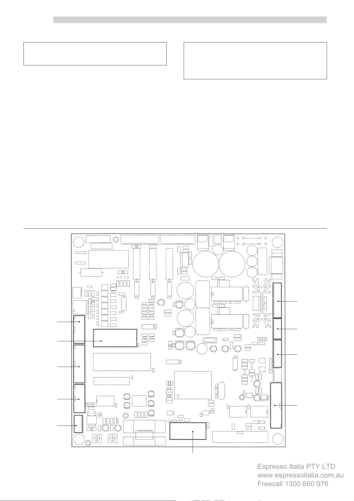
The CPU card shown in figure 1, illustrates the connections
for the accessories and payment systems described below
in this manual.
1 Parallel banknote reader 12/24V DC
2 MDB
3 Executive and BDV
4 Saeco Card
5 Parallel coiner 24V DC
6 Parallel coiner 12V DC
7 Token box 12V DC
8 Interface connector 7P/8P
9 Clock module (TIME KEEPER)
10 Nation key / programming key
8
9
5
6
7
2
1
2
3
4
10
Fig. 1
Page 3
English
Espresso Italia PTY LTD
www.espressoitalia.com.au
Freecall 1300 660 976
2 ACCESSORIES
2.1 Connecting up the clock
module (TIME KEEPER)
Maintenance Technician
This operation should be carried out by the Maintenance
Technician.
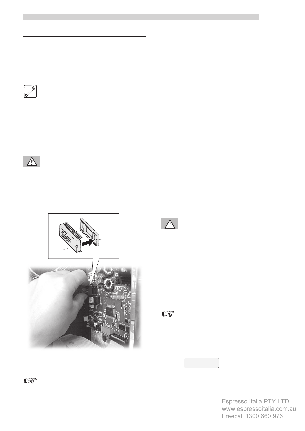
To connect up the clock module, proceed as follows:
- open the front door of the vending machine;
- insert the clock module into the connector (9 – Fig. 1)
of the CPU card (Fig. 2).
Warning
Connect the clock module in such a way that reference A
(on its back) aligns with reference B, which is to be found
on the base of the connector.
2.1.1 TIME KEEPER functions in
the programming menus
Sales management
In this menu there is the possibility of entering 2
differentiated price settings (DIFFERENTIATED PRICES 1;
DIFFERENTIATED PRICES 2), which come into operation
only during certain periods of the day.
Timetable management
Besides the ALWAYS FREE and NEVER FREE functions, this
menu also allows to enter time periods in which the selected
beverages are supplied either FREE of charge or with the
two DIFFERENTIATED PRICES (example: FREE - Monday –
ON=20:00 – OFF=24:00. Selections will be free every
Monday during the time period 20:00 to 24:00).
The DIFFERENTIATED PRICES 1 and 2 (linked to each
selection) may be entered in the same way.
In addition, it is possible to set the timetable for turning the
device on and off.
A
Fig. 2
Warning
B
The time periods for the same function must NOT overlap.
System management
In this menu it is possible to access the CLOCK function,
which allows you to enter the hour, minutes, month and
year.
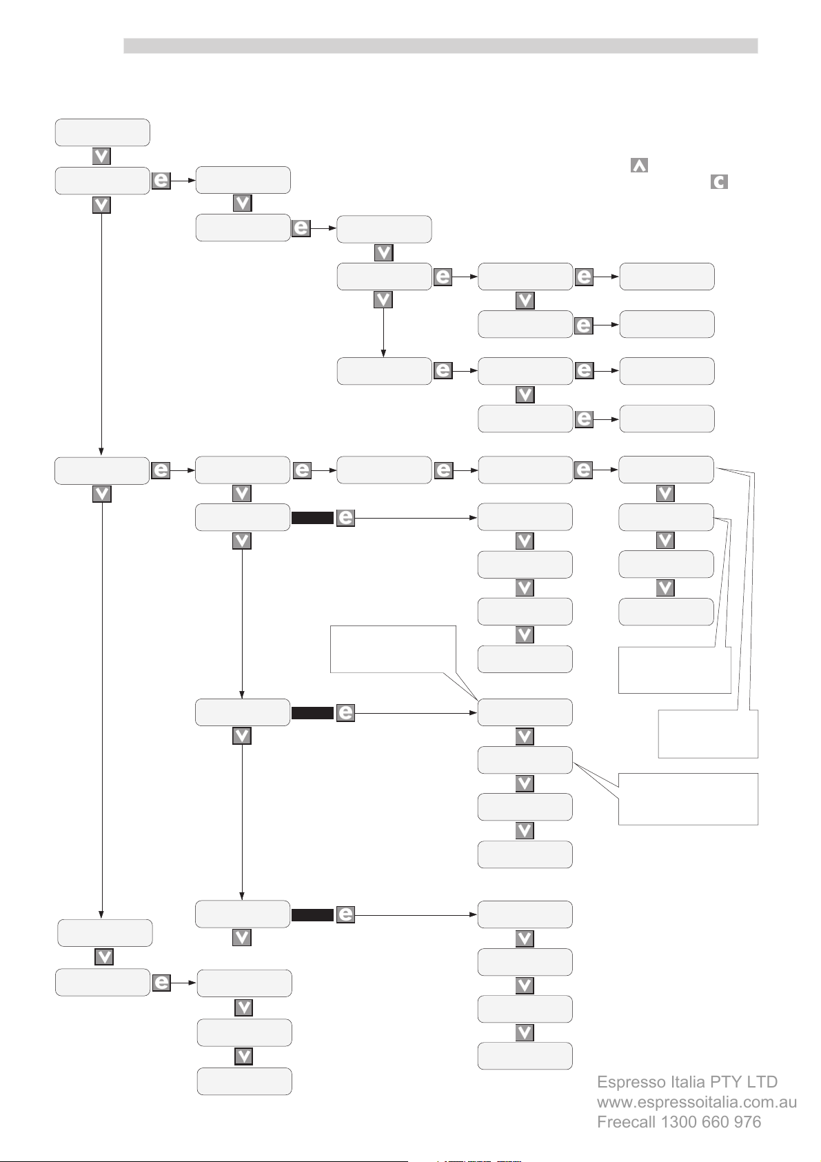
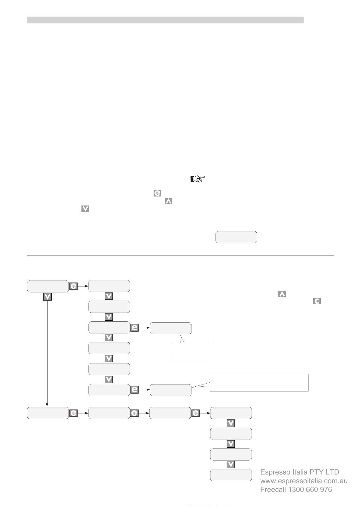
Important
The illustration on page 4 shows the functions of the TIME
KEEPER within the programming menus.
The messages in bold type identify the functions controlled
by the TIME KEEPER.
Example:
PRICES
DIV. 1
Important
The functions controlled by the TIME KEEPER are described
below in points 2.1.1 and 2.1.2.
3
Page 4
English
Espresso Italia PTY LTD
www.espressoitalia.com.au
Freecall 1300 660 976
PASSWORD
<13753>
SALES
MANAGEMENT
PRICES TABLE
PROGRAMMING MENU
N.B.
To scroll back to the previous menus,
press the key , to return to the
previous levels, press the key .
TIME
MANAGEMENT
PRICES
SELECTIONS
FREE VEND
NEVER
ON/OFF TIME
>NO<
PRICES STANDARD
PRICES
DIV. 1
PRICES
DIV. 2
FREE VEND
ALWAYS
con YES
Day and hour of time
period enabling price
D1
GLOBAL
PROGRAMMING
SINGLE
PROGRAMMING
GLOBAL
PROGRAMMING
SINGLE
PROGRAMMING
FREE VEND
TIME RANGE
ON/OFF ON1
mtwtfss 00:00
ON/OFF OFF1
mtwtfss 00:00
ON/OFF ON2
mtwtfss 00:00
ON/OFF OFF2
mtwtfss 00:00
DIV. PRICES 1
GL: >01< >0065<
DIV. PRICES 1
S 11: >01< >0070<
DIV. PRICES 2
GL: >01< >0060<
DIV. PRICES 2
S 16: >01< >0040<
FREE VEND ON1
mtwtfss 00:00
FREE VEND OFF1
mtwtfss 00:00
FREE VEND ON2
mtwtfss 00:00
FREE VEND OFF2
mtwtfss 00:00
Day and hour of
time period
disabling
PAYMENT
SYSTEM
SYSTEM
MANAGEMENT
PRICES D1
>NO<
PRICES D2
>NO<
V. M. CODE
>0000<
TEMPERATURE
>00<
CLOCK
>00:00 T16 JEN 01<
con YES
con YES
PRICES D1 ON1
mtwtfss 00:00
PRICES D1 OFF1
mtwtfss 00:00
PRICES D1 ON2
mtwtfss 00:00
PRICES D1 OFF2
mtwtfss 00:00
PRICES D2 ON1
mtwtfss 00:00
PRICES D2 OFF1
mtwtfss 00:00
PRICES D 2 ON2
mtwtfss 00:00
PRICES D2 OFF2
mtwtfss 00:00
Day and hour of
time period
enabling
Day and hour of time
period disabling price D1
4
Page 5
English
Espresso Italia PTY LTD
www.espressoitalia.com.au
Freecall 1300 660 976
2.1.2 Functions of the TIME KEEPER
in the maintenance menus
Statistics
This function allows the user to view all the sales statistics
registered by the vending machine.
D.A. code: assigned by the manager.
Coins total: the total number of coins entered is
displayed.
Banknote total: the total number of banknotes entered
is displayed.
Overpay: determines the maximum time period (in
seconds) after which the vending machine
absorbs the remaining credit shown on the
display.
In order to change the setting, press ; the
luminous cursor appears and, using the
and/or keys, it is possible to change the
setting. The time period may be adjusted in
intervals of ten seconds; when the “000” setting
is entered, the function is not operative.
Free selections: the total number of free selections
dispensed is shown.
Total sales: this displays the total obtained from
the sale of all the selections carried
out at NORMAL, DIFF. 1 and DIFF. 2
prices. The number of selections
dispensed at each price is displayed
as well.
Partial counters
In this menu it is possible to view the figures on the selections
dispensed by the vending machine (NORMAL; FREE;
DIFFERENTIATED 1; DIFFERENTIATED 2) only if the TIME
KEEPER is present after the last reset.
Important
The diagram that follows shows the functions of the TIME
KEEPER within the maintenance menus.
The messages written in bold type identify the functions
controlled by the TIME KEEPER.
Example:
STANDARD nm
>00000<
STATISTIC
PARTIAL
COUNTERS
V. M. CODE
>000000<
TOTAL COINS
TOTAL BANKNOTES
OVERPAY
SELECTION
FREE VEND >00000<
TOTAL SALES
TOTAL SELECTIONS
>00<
>00<
>00<
>00<
>00000<
MAINTENANCE MENU
BANKNOTES xx
>00<
Four different
banknotes can be
visualized
It is possible to view the number of selections
PRICE 02
>00<
SELECTION nm
>00000<
dispensed for each price.
STANDARD nm
DIVERSIF. 1 nm
N.B.
To scroll back to the previous menus,
press the key , to return to the
previous levels, press the key .
>00000<
>00000<
DIVERSIF. 2 nm
>00000<
FREE VEND nm
>00000<
5
Page 6

English
Espresso Italia PTY LTD
www.espressoitalia.com.au
Freecall 1300 660 976
2.2 Programming key
Maintenance Technician
This operation should be carried out by the Maintenance
Technician.
The programming key allows to transfer the data entered
into the following sections of the programming menu:
- SALES MANAGEMENT. ” It is possible to transfer
all the data;
- TIMETABLE MANAGEMENT. ” It is possible to
transfer all the data;
- PAYMENT SYSTEMS. ” It is possible to transfer all
the data;
- SYSTEM MANAGEMENT. ” It is possible to transfer
all the data, with the exception of the code of the SERIAL
NUMBER and of the PASSWORD.
The connector (10 - Fig. 1) for the programming key is the
same as that for the nation key.
To connect up the programming key, proceed as follows:
- open the front door of the vending machine;
- slide out the nation key from the connector (10 – Fig.
1);
- connect up the programming key to the same connector
as the nation key (Fig. 3).
When the device is next turned on, the display will show
the message: “TRANSFER KEY - RIGHT MODEL”, if the
key connected corresponds to the vending machine model
(example A), or “TRANSFER KEY - WRONG MODEL”, if
the key connected does not correspond to the vending
machine model (example B).
In case A, it is possible to transfer the parameters from the
vending machine to the programming key and vice-versa.
A
TRANSFER KEY
RIGHT MODEL
DATA TRANSFER
SAVING DATA
DATA TRANSFER
KEY -> VMC
DATA TRANSFER
VMC -> KEY
DATA TRANSFER
READING DATA
DATA TRANSFER
WRITING DATA
In case B, it is only possible to transfer the parameters
from the vending machine to the programming key.
B
TRANSFER KEY
WRONG MODEL
DATA TRANSFER
VMC -> KEY
DATA TRANSFER
WRITING DATA
6
NOTE
To go back to the previous menus, press the key; to go
back to the previous levels, press the key.
Any errors that may occur during the data transfer phase
are displayed with the message “TRANSFER KEY - ERROR
IN KEY DATA”. Should this message appear, repeat the
data transfer procedure; if the error continues to appear,
contact an AUTHORISED CUSTOMER SERVICE CENTRE.
Important
When the data transfer has been completed, reinsert the
nation key as per the instructions given in the operation
and maintenance manual for the automatic vending
machine BP 56 e BP 36.
Fig. 3
Page 7

3 PAYMENT SYSTEMS
Espresso Italia PTY LTD
www.espressoitalia.com.au
Freecall 1300 660 976
3.1 Installing the SAECO CARD
Maintenance Technician
This operation should be carried out by the Maintenance
Technician.
Assembly kit (Fig. 4)
A 1 universal module;
B 1 antenna;
C biadhesive plate;
D protective linen band;
E 1 adhesive label for the reading position of the SAECO
CARD;
F flat cable.
English
- apply the antenna (B – Fig. 4) to the protective panel
of the operating instructions label (Fig. 6);
Fig. 6
F
E
B
D
C
A
Fig. 4
Installation
Before installing, make sure that the TIME KEEPER clock
module is fitted (point 2.1).
Then, proceed as follows:
- open the front door of the vending machine;
- apply the biadhesive plate (C – Fig. 4) to the back of
the antenna (Fig. 5);
- apply the linen cloth (D – Fig. 4) so as to completely
protect the antenna (Fig. 7);
Fig. 7
Fig. 5
7
Page 8

English
Espresso Italia PTY LTD
www.espressoitalia.com.au
Freecall 1300 660 976
- On the BP 56 position the universal module (A – Fig.
4) by hooking it onto the 4 supporting pins (Fig. 8);
Universal module
support pins
Fig. 8
- On the BP 56 connect the flat cable (F - Fig. 4) to the
connector of the universal module (Fig. 9);
- On the BP 36 position the universal module (A – Fig.
4) by hooking it onto the 4 supporting pins (Fig. 8a);
Universal module
support pins
Fig. 9
- On the BP 36 connect the flat cable (F - Fig. 4) to the
connector of the universal module (Fig. 9a);
8
Fig. 8a
Fig. 9a
Page 9

- On the BP 56 connect the far end of the flat cable (F –
Espresso Italia PTY LTD
www.espressoitalia.com.au
Freecall 1300 660 976
Fig. 4) to the connector (4 – Fig. 1) of the CPU card
(Fig. 10);
English
Fig. 10
- On the BP 36 connect the far end of the flat cable (F –
Fig. 4) to the connector (4 – Fig. 1) of the CPU card
(Fig. 10a);
Fig. 11
Important
The label indicates the area in which the SAECO CARD is
positioned.
3.1.1 Functions of the SAECO CARD
in the programming menus
Sales management
This menu allows to access the SAECO CARD DISCOUNT
function, where the discount value can be entered. This
discount is applied to users who purchase products with
the SAECO CARD system.
In order to change the value, press ; a luminous cursor
appears and, by using the and/or keys, it is possible
to change the setting.
- apply the adhesive label (E – Fig. 4) to the outer part
of the panel in correspondence with the antenna (Fig.
11).
Fig. 10a
Payment system
This menu allows you to access the following function:
- MAX CARD CHARGE. Here you can set the maximum
amount of credit that may be charged on the SAECO
CARD. The possible values range from the banknote
minimum (preset by the nation key) and the maximum
charge allowed by the universal module. Any cards
with a credit greater than the value entered will not be
accepted by the vending machine.
9
Page 10

English
Espresso Italia PTY LTD
www.espressoitalia.com.au
Freecall 1300 660 976
Important
3.1.2 Functions of the SAECO CARD
in the maintenance menu
The diagram that follows shows the functions of the SAECO
CARD in the programming menus.
The messages written in bold type identify the functions
controlled by the SAECO CARD.
Example:
DISCOU. SAECO CARD
>00<
PROGRAMMING MENU
PASSWORD
<13753>
SALES
MANAGEMENT
TIME
MANAGEMENT
PRICES
TABLE
PRICES
SELECTIONS
DISCOU. SAECO CARD
>00<
Statistics
This menu allows you to access the following functions:
- CARD IN. Displays the amount transferred from the
card to the automatic vending machine;
- CARD OUT. Displays the amount transferred from the
vending machine to the card;
- SAECO CARD DISCOUNTS. Displays the total for all
the dispensing operations made with the SAECO CARD
applying the discount.
Important
The diagram that follows shows the functions of the SAECO
CARD within the programming menus.
The messages written in bold type identify the functions
controlled by the SAECO CARD.
Example:
CARD-OUT
>00<
PAYMENT
SYSTEM
Important
COIN
VALUES
BANKNOTES
VALUES
PROTOCOL
EXECUTIVE
MULTIVEND
>YES<
OVERPAY TIME
>000<
MAX CARIC. CARD
>00000<
MAINTENANCE MENU
STATISTIC
V. M. CODE
TOTAL COINS
TOTAL BANKNOTES
CARD-IN
CARD-OUT
OVERPAY
DISCOU. SAECO CARD
>0000000<
>00<
>00<
>00<
>00<
>00<
>00<
The programming procedures are shown in the operation
and maintenance manual of the automatic vending
machine BP 56 e BP 36.
10
Important
The maintenance procedures are reported in the operation
and maintenance manual of the automatic distributor BP
56 e BP 36.
Page 11

English
Espresso Italia PTY LTD
www.espressoitalia.com.au
Freecall 1300 660 976
3.2 Installing the CHANGEGIVING COINER
Maintenance Technician
This operation should be carried out by the Maintenance
Technician.
Assembly kit
- 1 change-giving coiner (not supplied by the SAECO
INTERNATIONAL GROUP);
- 1 connecting cable (supplied on the basis of the coiner
protocol, available from the SAECO INTERNATIONAL
GROUP).
Installation
Proceeds as follows:
- open the front door of the vending machine;
- mount the CHANGE-GIVING COINER by hooking it
to the three pins on the plate (Fig. 12).
Pins of the coiner
support plate
- connect the cable provided to the connector in the coiner
(Fig. 13);
Fig. 13
- connect the other end of the cable provided to the
connector (2÷7 - Fig. 1) on the CPU card (example:
Fig. 14);
Fig. 12
Fig. 14
- program the device by setting the communications
protocol.
Important
The programming procedures are shown in the operation
and maintenance manual for the automatic distributor BP
56 e BP 36.
Information on the coiner is provided in the instructions
booklet for the coiner itself.
11
Page 12
English
Espresso Italia PTY LTD
www.espressoitalia.com.au
Freecall 1300 660 976
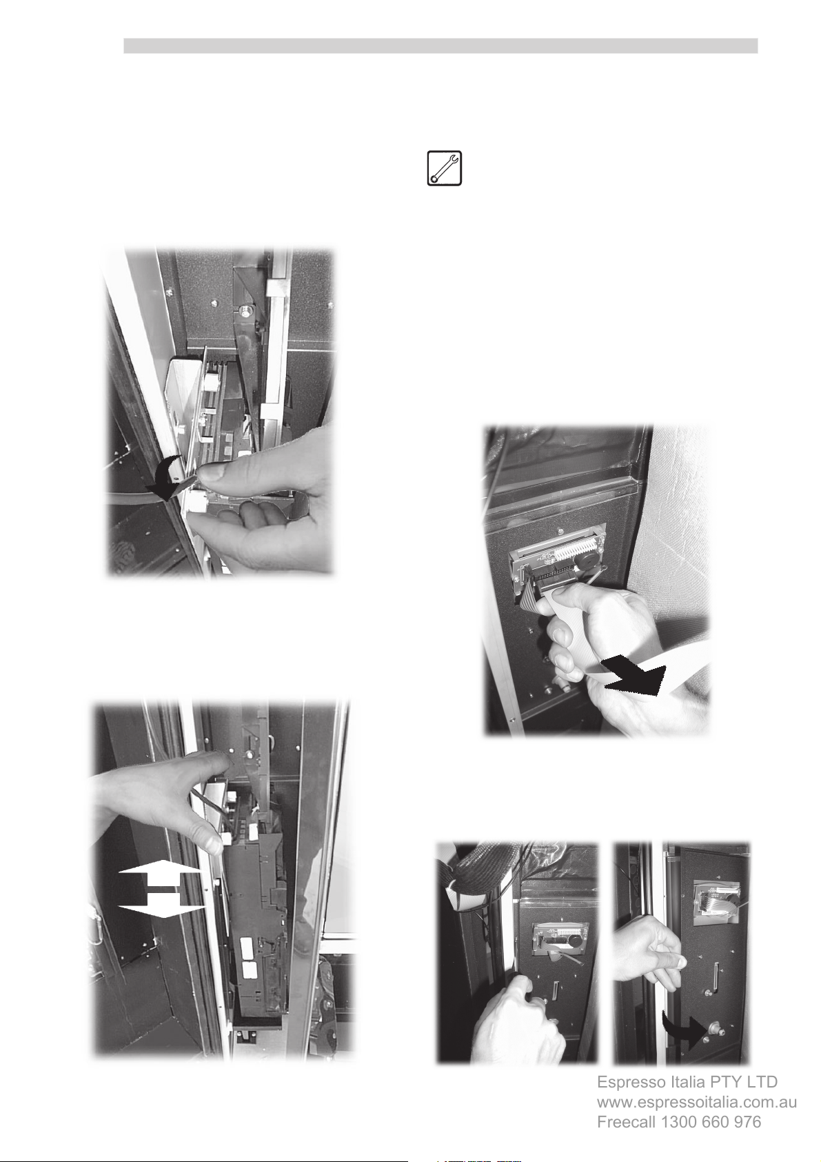
- check that the coins slide through correctly and that
the button for retrieval of change is functioning properly.
If there are any problems relating to the sliding of coins,
the coiner should be adjusted in the following manner:
- unscrew the two knobs of the support plate (Fig. 15);
3.3 Installing the BANKNOTE
READER
Maintenance Technician
This operation should be carried out by the Maintenance
Technician.
Assembly kit
- 1 banknote reader;
- 1 banknote reader support panel.
Installation
Proceed in the following manner:
- open the front door of the vending machine;
- disconnect the cable from the connector (Fig. 17);
Fig. 15
- slide the coiner support plate sideways so as to have
the coin slot align perfectly with the coin guide device
(Fig. 16).
Fig. 17
- remove the four fastening screws and the keyboard
panel (Fig. 18);
12
Fig. 16
Fig. 18
Page 13

English
Espresso Italia PTY LTD
www.espressoitalia.com.au
Freecall 1300 660 976
- remove the four fastening screws and the panel to be
replaced (Fig. 19);
Fig. 19
- position the panel that supports the banknote reader
at the same point as the panel that has just been
removed (Fig. 20);
- slide the slots of the BANKNOTE READER onto the
support pins on the panel (Fig. 22);
Fig. 20
- re-attach the upper panel of the keyboard and
reconnect the cable to the connector (Fig. 21);
Fig. 22
- tighten the three fastening nuts (Fig. 23);
Fig. 21
Fig. 23
13
Page 14
English
Espresso Italia PTY LTD
www.espressoitalia.com.au
Freecall 1300 660 976
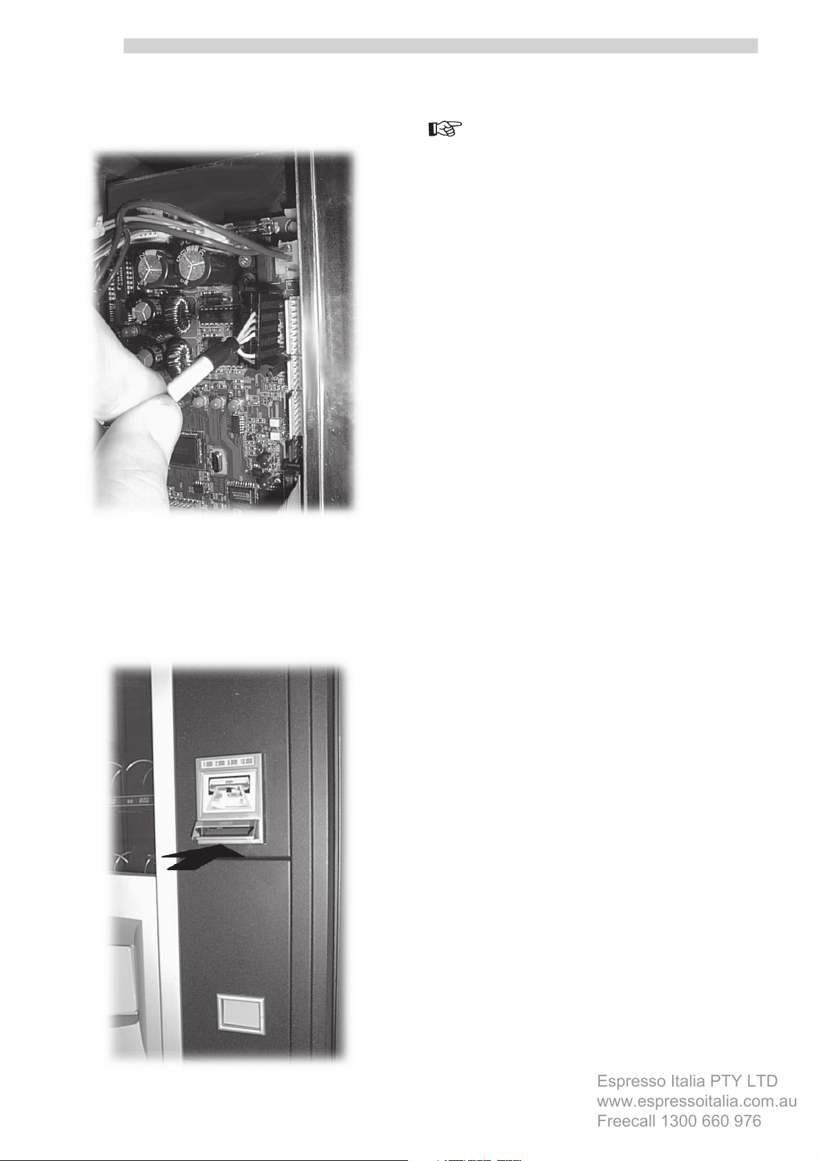
- connect the BANKNOTE READER cable to the connector
(1 – Fig. 1) of the CPU card (Fig. 24);
Important
The programming procedures are shown in the operation
and maintenance manual for the automatic vending
machine BP 56 e BP 36.
In the event that both a CHANGE-GIVING COINER and a
BANKNOTE READER must be fitted to the same vending
machine, the latter should be installed in the position of
the instructions panel. In such a case, the instructions
label should be affixed under the keyboard.
Fig. 24
- program the device by setting the communications
protocol. In the case of a parallel BANKNOTE READER,
the values of the banknotes must be entered. Carry out
tests by inserting banknotes into the slot of the reader
(Fig. 25).
14
Fig. 25
Page 15

Espresso Italia PTY LTD
www.espressoitalia.com.au
Freecall 1300 660 976
Page 16

Espresso Italia PTY LTD
www.espressoitalia.com.au
Freecall 1300 660 976
Cod. 1602.978 - 01 12/01
 Loading...