

Page 1
Project Team 1
Christopher Clark
Danielle Launay
Jonathan Lin
John Sequeira
Rishi Wadhera
Ryobi Reciprocating Saw
October 11, 2005
Computer Aided Drafting
14:650:388:01
Page 2

Objective:
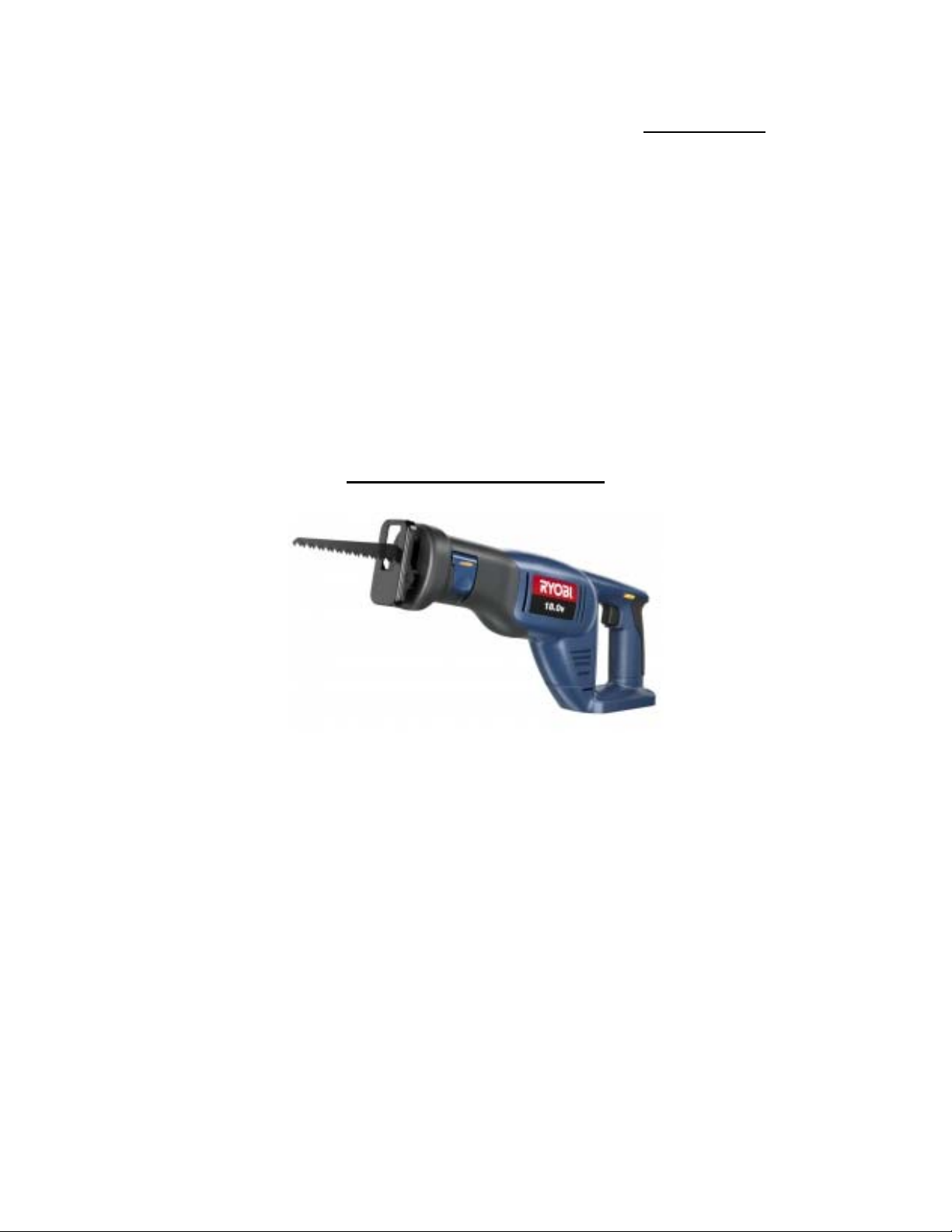
In this project, our main objective is to effectively model the Ryobi ® Variable
Speed Reciprocating Saw. It runs through normal 120-V alternating current power. When
on, the saw blade has a stroke of 19/16 inches moving at a maximum speed of 2800
strokes per minute. The entire assembly, including the removable blade, weights 6.3
pounds. The saw has 6 speed settings, a trigger which determines whether the saw is on
or off, and interchangeable blades. After completing the model and asse mbling it, we will
attempt to animate several aspects of the construction and functions of the saw. Finally,
we will end with an ANSYS analysis of the saw to determine certain limits, for example
under what load the blade would break, and what would be the strongest material through
which the blade can cut.
Challenges:
In undertaking our task, there are many difficulties that arise. First, the saw is
designed for maximum user comfort. That means that the external shell is contoured for
the human hand, with different grips and conveniences. These, as a whole, may be
difficult to model in ProE. A second complexity will be precisely measuring the size of
the pieces to ensure that our assembly comes together correctly. Because of the odd
external shape, some of the internal components are also oddly designed. We must also
take care in disassembling the model so that we do not damage any of the pieces. Finally,
there are approximately 50 different parts to be modeled. Having that many parts to
assemble creates complexities in and of itself.
A schematic of the saw follows
Page 3

Page 4

Part Number Name
1 Cover Plate
2 Gear Case Seal
3 Gear Case Cover
4 Spring Washer
5 Screw (M4 x 18mm)
6 Seal
7 Screw (M4 x 10mm)
8 Cover Plate
9 Guide Block
10 Saw Bar Assembly
11 Yoke Plate
12 Retaining Ring
13 Roller Bearing
14 Gear Assembly
15 Screw (M4 x 16mm)
16 Shaft Mounting Plate
17 Ball Bearing
18 Gear Shaft
19 Ball Bearing
20 Blade Release Lever
21 Spring
22 Pin
23 Gear Case
24 Lock Washer
25 Screw
26 Screw
27 Rubber Boot
28 Guard Plate
29 Shoe Assembly
30 Saw Blade
31 Bearing Retainer
32 Screw (M3 x 8mm)
33 Retaining Ring
34 Armature
35 Baffle
36 Screw
37 Field
38 Housing Assembly
39 Logo Plate
40 Bend Relief
41 Power Cord
42 Cord Clamp
43 Screw (M4 x 16mm)
44 Speed Control Board
Page 5

45 Switch
46 Lead Assembly
47 Screw
48 Data Plate
49 Trigger
50 Brush Tube Assembly
51 Carrying Case
Expected Results:
After modeling all the parts in ProE, we expect to be able to assemble the pieces
together and animate them to show how the saw operates. Hopefully, we will animate the
creation process, the normal function of the saw, and the removal/addition of a blade.
After that, we hope to be able to use an ANSYS analysis to see the forces acting on
different portions of the saw, focusing specifically on the blade and casing. Hopefully, we
will be able to find the yield stress of the blade and the maximum hardness of the
materials through which it can cut.
Work Distribution:
Christopher Clark: Outer Casings
Writing Assignments/Presentations
Danielle Launay: Gears/Bearings
Screws
Jonathan Lin: Switches
Speed Control Mechanism
Power Cord
John Sequeira: Saw Blades
Blade Retainer Mechanism
Rishi Wadhera: Plates/Washers
Shafts
We will all be equally responsible for the assembly and animation of the pieces, and for
the force analysis portion of the project. We do, though, reserve the right to change these
responsibilities as necessary, or to suit a particular members strongest abilities.
References:
http://www.ryobi.com
http://oneworld1.inetu.net/manuals/ryobi/RJ162VK_628_r.pdf
The Ryobi ® Variable Speed Reciprocating Saw from which our models will be created.
 Loading...